

Page 1
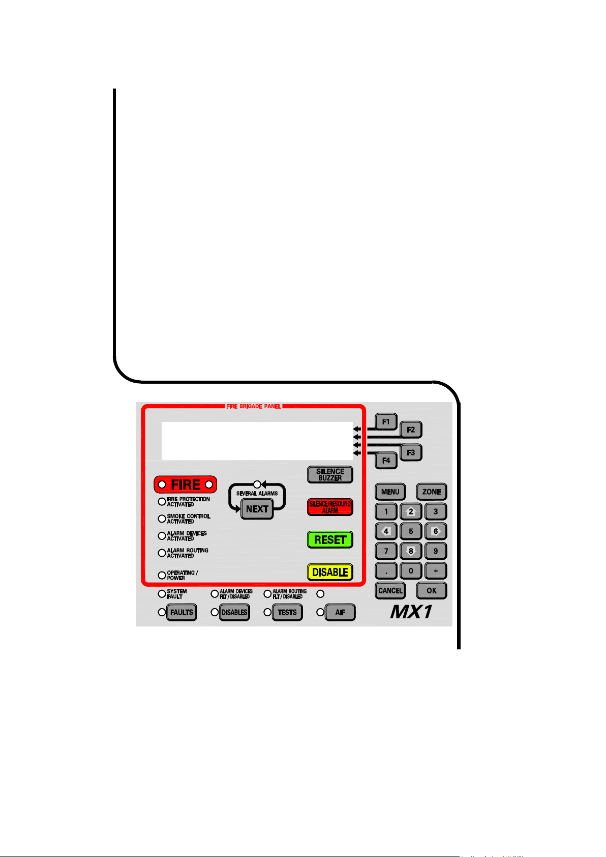
Vigilant MX1
Fire Alarm System
Operator Manual
LT0344
Issue 2.4
Vigilant MX1
Sample MX1 Fire Alarm System
MX1 V1.60 NZS 4512:2010 05:04:07
Normal 12/02/15
Page 2
Vigilant MX1 Operator Manual Document: LT0344
Fir
e
Fighter’s Interface
– New Zealand Operation
– Quick Reference
Smoke ALARM 2001 | MORE INFO
Reception | PREV
Atrium Entrance | NEXT
01 Zone Alarms Event 01 of 01 | ACK ALM
SEVERAL
ALARMS
Indicator
General
FIRE
Indicator
Alarm
Alerting
Devices
Indicator
Brigade
Alarm
Indicator
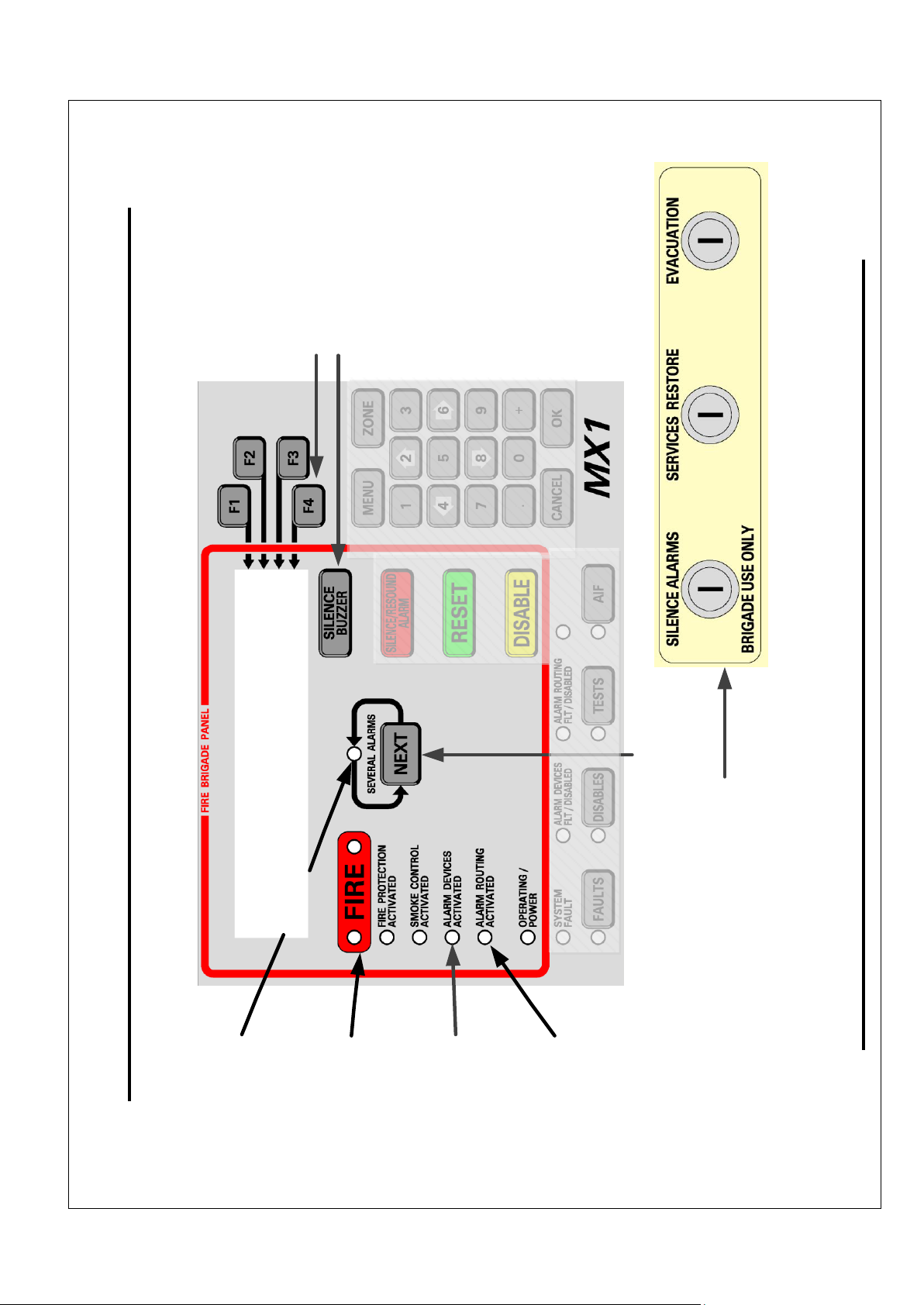
ACK key
SILENCE
BUZZER
key
Shaded
keys are
not active
NEXT
key
Brigade Keyswitches
Fire Fighter’s Interface, showing active keys and interfaces
.
Page ii 8 August 2017 Issue 2.4
Page 3

Document: LT0344 Vigilant MX1 Operator Manual
MORE
INFO
Key
– Function Key
F1 displays
additional
alarm
information. Th
is includes
the alarm
type
, zone action text, the
current level o
f the device causing the alarm
, and the time at
which the alarm occurred.
SILENCE
BUZZER
Key
– is used to silence the internal
buzzer in the panel
if it is on.
SILENCE ALARMS Keyswitch
– operating this switch
deactivates the alarm alerting devices (the Alarm Devices
indicator goes out). The FAULTS indicator will light and the fault
buzzer
may
sound (continuous
ly).
When this switch is restored to normal, all current alarms will be
automatically
disabled/isola
ted (the
DISABLES
indicator will light)
and the alarm detail display will be replaced by the general fault
display.
EVACUATION Keyswitch
– operating this switch activates the
alarm alerting devices.
SERVICES RESTORE Keyswitch
– operating this switch rest
ores
selected building services to normal operation after a fire alarm
(dependent on system configuration).
Other keys
- While the door is shut and the key turned fully
clockwise, all other keys on the keypad cannot be used.
Fire Fighter
’s Interface
– New Zealand Operation
– Quick Reference
– shows alarm detail: alarm type, zone/
tor
– is lit if there is any
– lit when there are
2 or more
rms
present
. Press
NEXT
to view
additional alarms
.
(red)
– is lit when the
devices (sounders, evacuation system
, etc
.) are
Indicato
r (red)
– is lit when a Fire
NEXT
Key
– steps the alarm display forward to the following
F3
key h
as the same effect.
– Function Key
F4
marks an alarm as acknowledged
– Function Key
F2
steps the alarm display
Issue 2.4 8 August 2017 Page iii
Page 4

Vigilant MX1 Operator Manual Document: LT0344
Welcome
The VIGILANT MX1 is an innovative analogue addressable fire indicator
panel incorporating the latest technology. It complies with New Zealand
Standards including NZS 4512:2010 and incorporates an integral Fire
Brigade Panel to the Australian standard AS 4428.3. It also complies with
Australian Standard AS 7240-2:2004. Its support for MX TECHNOLOGY,
fuzzy-logic detection algorithms and powerful control functions make it
suitable for a wide range of fire protection applications for small to large size
systems.
If your MX1
Requires
Service
Contact your service provider.
Maintenance
Contractor (1)
Job Reference #
_____________
Name:
Address:
Telephone
Office:
Mobile:
Maintenance
Contractor (2)
Job Reference #
_____________
Name:
Address:
Telephone
Office:
Mobile:
Maintenance
Contractor (3)
Job Reference #
_____________
Name:
Address:
Telephone
Office:
Mobile:
Installation
Data –
to be
completed
by installer
Installation Location
Name:
Date:
MX1 Serial Number
Panel Installed by
Name:
Date:
Telephone
Office:
Mobile:
Page iv 8 August 2017 Issue 2.4
Page 5

Document: LT0344 Vigilant MX1 Operator Manual
Manufacturer’s
Details
Manufacturer
The MX1 is manufactured for:
Johnson Controls
17 Mary Muller Drive
Hillsborough, Christchurch 8022
NEW ZEALAND
Phone: +64 3 3895096
Fax: +64 3 3895938
Copyright
and
Trademark
Information
©2017 Johnson Controls. All Rights
Reserved. All specifications and other
information shown were current as of
document revision date and are subject to
change without notice.
VIGILANT, MX VIRTUAL, MX DIGITAL, and MX
FASTLOGIC are trademarks of Johnson
Controls. VESDA is a trademark of Xtralis Pty
Ltd.
No part of this document may be
reproduced or transmitted in any form or
by any means, electronic or mechanical,
for any purpose, without the express
written consent of Johnson Controls.
Document
Document Number: LT0344
Issue: 1.0 24 November 2004
1.1 28 August 2006
2.0 15 January 2010
2.1 1 November 2011
2.2 24 October 2013
2.3 27 February 2015
2.4 8 August 2017
Firmware Revision
1.70
Amendments
Re-branded manual to Johnson Controls.
Revised for V1.70 firmware and to include
AS 1668 fan controls, new FBP keypad
and MX devices.
Acknowledgements
(MX1 firmware incorporates
software from external sources.
This acknowledgement applies to
this external software.)
Copyright (c) 1990 The Regents of the University of California. All rights reserved.
This code is derived from software contributed to Berkeley by Chris Torek.
Redistribution and use in source and binary forms, with or without modification, are
permitted provided that the following conditions are met:
1. Redistributions of source code must retain the above copyright notice, this list of
conditions and the following disclaimer.
2. Redistributions in binary form must reproduce the above copyright notice, this list of
conditions and the following disclaimer in the documentation and/or other materials
provided with the distribution.
3. All advertising materials mentioning features or use of this software must display the
following acknowledgement:
This product includes software developed by the University of California, Berkeley
and its contributors.
4. Neither the name of the University nor the names of its contributors may be used to
endorse or promote products derived from this software without specific prior written
permission.
THIS SOFTWARE IS PROVIDED BY THE REGENTS AND CONTRIBUTORS ``AS IS'' AND
ANY EXPRESS OR IMPLIED WARRANTIES, INCLUDING, BUT NOT LIMITED TO, THE
IMPLIED WARRANTIES OF MERCHANTABILITY AND FITNESS FOR A PARTICULAR
PURPOSE ARE DISCLAIMED. IN NO EVENT SHALL THE REGENTS OR
CONTRIBUTORS BE LIABLE FOR ANY DIRECT, INDIRECT, INCIDENTAL, SPECIAL,
EXEMPLARY, OR CONSEQUENTIAL DAMAGES (INCLUDING, BUT NOT LIMITED TO,
PROCUREMENT OF SUBSTITUTE GOODS OR SERVICES; LOSS OF USE, DATA, OR
PROFITS; OR BUSINESS INTERRUPTION) HOWEVER CAUSED AND ON ANY THEORY
OF LIABILITY, WHETHER IN CONTRACT, STRICT LIABILITY, OR TORT (INCLUDING
NEGLIGENCE OR OTHERWISE) ARISING IN ANY WAY OUT OF THE USE OF THIS
SOFTWARE, EVEN IF ADVISED OF THE POSSIBILITY OF SUCH DAMAGE.
Issue 2.4 8 August 2017 Page v
Page 6
Vigilant MX1 Operator Manual Document: LT0344
Warning
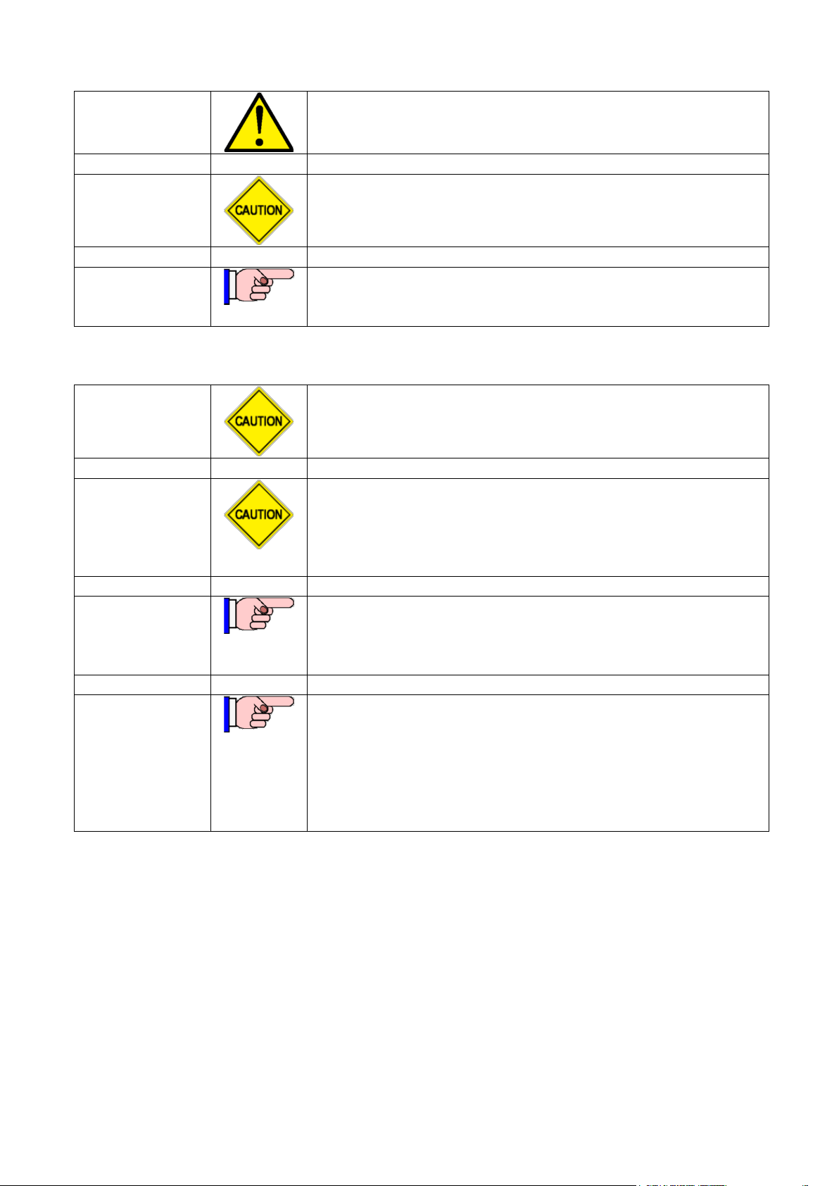
Symbols Used
in this Manual
Danger! Failure to comply may lead to serious injury and/or
property damage.
Caution – failure to comply may result in incorrect,
unpredictable or unstable operation.
Indicates useful or important information.
Cautions &
Warnings
This is a Class A product. In a domestic environment this
product may cause radio interference, in which case the
user may be required to take adequate measures.
Some of the operation of the MX1 as described in this
manual is dependent on the site-specific configuration
performed by the installer. If the configuration is nonstandard, then operation may differ from this manual and
compliance to local Standards may be invalidated.
The MX1 has facilities to protect against unauthorised use
of operator controls by means of Access Levels. The
configuration of your system may result in Access Levels
that differ in some respects from this manual.
Except where otherwise stated, this manual refers to MX1
Controller firmware version 1.70.
Information provided in this manual may remain valid for
subsequent versions of Controller firmware. However if a
different version of firmware is installed, a more appropriate
version of this manual may be required.
Page vi 8 August 2017 Issue 2.4
Page 7

Document: LT0344 Vigilant MX1 Operator Manual
Table of Contents
Chapter 1 Introduction ........................................................................ 1-1
How to Use this Manual _________________________________ 1-2
System Operation ______________________________________ 1-3
Basic System Function __________________________________ 1-4
Operator Interface ______________________________________ 1-5
Normal Appearance of Operator Interface ___________________ 1-6
Description of Operator Interface __________________________ 1-6
Operator Commands ____________________________________ 1-10
Operator Access Levels _________________________________ 1-11
Smoke Control/AS 1668 Fan Panel ________________________ 1-12
Terminology Used in this Manual __________________________ 1-12
Nuisance Alarms _______________________________________ 1-18
Chapter 2 Managing Alarm Conditions ............................................. 2-1
Viewing Alarms ________________________________________ 2-2
Resetting Zones in Alarm ________________________________ 2-4
Disabling Zones in Alarm ________________________________ 2-5
Alarms From Other Sources ______________________________ 2-5
Chapter 3 Managing Faults and Disables ......................................... 3-1
Viewing Faults _________________________________________ 3-2
Viewing Disables _______________________________________ 3-4
Disable Menu Options ___________________________________ 3-6
Chapter 4 Viewing the Event History ................................................. 4-1
General Message Format ________________________________ 4-1
Viewing Event History ___________________________________ 4-2
Zone Events __________________________________________ 4-3
Point Events __________________________________________ 4-5
System Events ________________________________________ 4-6
Chapter 5 Recalling Zone and Point Status ...................................... 5-1
Recall Menu Options ____________________________________ 5-2
Recalling Off-Normal Points and Zones _____________________ 5-3
Using the Zone Button to Recall Points and Zones ____________ 5-8
Chapter 6 Zone and Point Functions ................................................. 6-1
Displaying Zone or Point Command Menu ___________________ 6-2
Resetting Zones or Points ________________________________ 6-2
Disabling and Enabling Points or Zones _____________________ 6-6
Testing Zones _________________________________________ 6-12
Testing Points _________________________________________ 6-16
Viewing Point Values and Settings _________________________ 6-18
Issue 2.4 8 August 2017 Page vii
Page 8

Vigilant MX1 Operator Manual Document: LT0344
Chapter 7 Logging On to Access Level 3 .......................................... 7-1
Logging On to Access Level 3 ____________________________ 7-1
Chapter 8 Other Service Functions ................................................... 8-1
Front Panel Display Test _________________________________ 8-1
Setting System Time and Date ____________________________ 8-2
Power Supply Status and Battery Testing____________________ 8-3
MX Loop Status ________________________________________ 8-5
System Memory Status __________________________________ 8-7
Test System __________________________________________ 8-10
Test Alarm Devices _____________________________________ 8-11
Replacing an MX Device _________________________________ 8-12
Buzzer Disable and Mute ________________________________ 8-14
Commissioning Mode (Access Level 3) _____________________ 8-16
Resetting the System (Access Level 3) _____________________ 8-17
Chapter 9 Networking ......................................................................... 9-1
In this Chapter _________________________________________ 9-2
Zone & Point Numbering _________________________________ 9-2
Tandem Mode _________________________________________ 9-3
Network Interface Device Points ___________________________ 9-5
Network Status Points ___________________________________ 9-5
Network Comms Status __________________________________ 9-6
Network MAF Status ____________________________________ 9-7
Network Fault Status ____________________________________ 9-10
Network Warning Status _________________________________ 9-11
Chapter 10 Buzzer Cadences, LCD Error Messages and Fault Finding 10-1
Buzzer Cadences ______________________________________ 10-1
Troubleshooting – LCD Messages and Actions _______________ 10-1
Quick Reference – Alphabetical List of Possible LCD Messages __ 10-8
Chapter 11 System Information ....................................................... 11-1
Equipment Point Descriptions _____________________________ 11-2
Page viii 8 August 2017 Issue 2.4
Page 9

Document: LT0344 Vigilant MX1 Operator Manual
Topic
See Page
How to Use this Manual
1-2
System Operation
1-3
Basic System Function
1-4
Operator Interface
1-5
Normal Appearance of Operator Interface
1-6
Description of Operator Interface
1-6
Operator Commands
1-10
Operator Access Levels
1-11
Smoke Control/AS 1668 Fan Panel
1-12
Terminology Used in this Manual
1-12
Nuisance Alarms
1-18
Chapter 1
Introduction
Introduction
In this Chapter
This chapter provides an overview of the VIGILANT MX1 system function
and describes the normal appearance of the operator interface.
It also describes the concept of Access Levels for access to commands,
and the conventions used in this manual to refer to parts of the display
when describing these commands.
Refer to the page number listed in this table for information on a specific
topic.
Issue 2.4 8 August 2017 Page 1-1
Page 10

Vigilant MX1 Operator Manual Document: LT0344
How to Use this Manual
Intended Use
Organisation of Chapters
Servicing and Maintenance
This manual covers the operations and displays available on the MX1’s
front panel. This manual is intended for use by building owners and
managers, fire brigade staff, and front line service staff. It assumes that
the reader has a basic knowledge of automatic fire alarm systems.
It does not cover:
system design, or installation and operational requirements specified
in local standards or building codes.
more detailed service functions that require access to the inside of the
cabinet, or use of more advanced diagnostic functions for fault finding
or performance analysis.
These and other topics are covered in the “MX1 System Design Manual”,
part number LT0361 and the “MX1 Service Manual”, part number
LT0366.
The topics in this manual are generally arranged in decreasing order of
urgency. Firefighter use of the Fire Brigade Panel (f.b.p.) is shown inside
the front page, with a detailed section on dealing with alarms in Chapter
2.
This is followed by less urgent actions, dealing with Faults and Disables,
Point and Zone Status Recalls, Testing, and System Status Recall,
followed by a description of error messages and system points.
To obtain continued high-reliability operation from the MX1 it is
necessary to have it regularly tested and maintained by trained and
qualified service-company personnel.
NZS 4512:2010 details the requirements for the testing and maintenance
of fire alarm systems. The MX1 Service Manual (LT0366) contains a
guide to the procedures for testing the MX1.
If changes are required to the site-specific configuration of the MX1 (for
example, if new detectors are required because of building alterations)
then this work must be carried out by a suitably trained and qualified firealarm service person and the “as-installed” information updated including
a record of the new site-specific configuration version. All system
changes must be fully tested and commissioning sheets completed. The
new site-specific configuration should be compared against the previous
version to ensure that there have been no unintentional changes.
A description of nuisance alarms and actions that can be carried out to
help reduce the incidence of them is given in “Nuisace Alarms” on page
1-18.
Page 1-2 8 August 2017 Issue 2.4
Page 11

Document: LT0344 Vigilant MX1 Operator Manual
Overview
System Operation
Physical
The VIGILANT MX1 is control and indicating equipment (c.i.e.) that forms
the central part of a fire detection and alarm system using MX analogue
addressable detectors.
It complies with the requirements of NZS 4512:2010 “Fire Detection and
Alarm Systems in Buildings”, AS 7240.2-2004 “Fire Detection and Alarm
Systems” and AS 4428.3-2010 “Fire Brigade Panel”.
Up to 250 MX devices (detectors and addressable input/ output modules)
may be connected to the in-built detection loop. Some devices support
multiple inputs and outputs which can be monitored and controlled
separately. Additional loops of up to 250 MX devices may be added to
the MX1 by fitting MX Loop Cards. The MX DIGITAL communication
protocol used on the detection loops provides high reliability and fault
tolerance. The MX1 uses software algorithms to evaluate the analogue
values returned from the detectors.
MX FASTLOGIC is a fuzzy logic based algorithm applied to photoelectric
smoke detectors. It is designed to discriminate between the smoke and
temperature patterns of real fires and the typical causes of nuisance
alarms. It supports three risk levels; High, Medium and Low.
SMARTSENSE is a field-proven, reliable detection algorithm, reducing
nuisance alarms, compensating for ambient conditions, with a wide range
of programmable sensitivity settings.
Both algorithms provide:
Detector pre-alarm sensing for early warning of a potential alarm.
Compensation for soiling and changes in ambient conditions.
Logging of “detector dirty alert” when compensation limits are about to
be exceeded, to allow service to be scheduled.
The MX1 is supplied in a compact metal cabinet with an integrated
Fire Brigade Panel and operator keypad and display. Space is provided
for Zone Status indicators in rear and front service formats.
One Remote Fire Brigade Panel (RFBP) may be connected to the MX1
panel to provide a remote operator interface or fire brigade attendance
point. This operates independently of the MX1 panel’s user interface, but
on the same internal data – zone and point status, buzzer on/off,
silence/mute, etc. Note, the Remote FBP can be configured so that its
keyboard cannot be used in alarm conditions (for example, when it is
installed for non-fire brigade use and it is necessary to avoid the Remote
FBP user interfering with the fire brigade’s alarm display).
Depending on the Remote FBP model zone LED displays may be
included.
Issue 2.4 8 August 2017 Page 1-3
Page 12

Vigilant MX1 Operator Manual Document: LT0344
Easy Operation
Basic System Function
Overview
Operation is straightforward using the MX1’s keypad and four line LCD.
The display provides clear and uncluttered indication of the alarm
location, including the zone and point numbers, and text description of
the zone and point in alarm.
The display allows easy scrolling through the time and date-stamped 99
alarm event buffer.
Current alarms, faults and disabled zones and points can also be
separately recalled and displayed. An internal history log stores the
previous 900 events, and these can also be recalled to the display.
The MX1 has five general functions:
It monitors fire detectors (smoke detectors, carbon monoxide
detectors, flame detectors, heat detectors, manual call points, etc.).
Note that some detectors may be multi-sensor, i.e., they contain
multiple sensors – for example a heat sensor, a smoke sensor and a
carbon monoxide sensor. The sensor values are processed
according to the programmed algorithm and determine whether a fire
condition exists.
It activates alarm devices (evacuation systems, sounders, strobes)
and alarm routing equipment (alarm signalling equipment) when a fire
alarm condition is detected.
It displays zone location descriptions and that of an affected device,
and optionally activates zone status indicators.
It monitors and controls ancillary building equipment (fan controls,
relays, door holders, etc.)
It supervises devices, transmission paths (circuits), and internal
functions of the MX1 to indicate a fault condition should there be a
problem.
The MX1 operator interface allows an operator to monitor and control the
site-specific components connected to the MX1.
Most manual controls and menu functions require Access Level 2 unless
otherwise noted. Access level 2 is entered by the use of a 003 pattern
key in the cabinet door lock. Those menu functions that could have an
adverse effect if inappropriately used require Access Level 3. See Page
1-11 for a description of Access levels.
Multiple MX1 fire panels, along with other devices, may be connected
together to form a network. For details please refer to Chapter 9
Networking.
Page 1-4 8 August 2017 Issue 2.4
Page 13
Document: LT0344 Vigilant MX1 Operator Manual
Office
Factory
Garage
Shed
Shop
Vigilant MX1
Sample MX1 Site Name
MX1 V1.60 AS 7240.2 05:40:47
Normal
11/02/15
Alphanumeric Liquid Crystal
Display (LCD)
Fire Brigade Panel
(FBP)
Soft Keys
Status
Indicators
Numeric
Keypad
Zone LED
Indicators
Fire
Brigade
Panel
Indicators
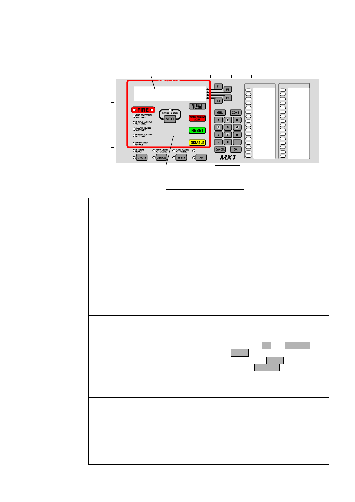
Table 1-1. Components of the Operator Interface
Component
Description
Alphanumeric
Liquid Crystal
Display (LCD)
Displays details about alarms, faults, and other service-related
system information, as well as menus of command options and
messages.
The information normally displayed in the LCD, without operator
intervention, is called the “base display”.
Fire Brigade Panel
(f.b.p.)
Controls and indicators within the red border are for use by fire
brigade personnel during alarm attendance. See the quick
reference guide at the front of the manual, or page 2-2 for more
detail.
Soft Keys
These keys have different functions, depending on the current
display. Each key’s function at any time is shown by the text
displayed at the right side of the LCD.
Status Indicators
LED indicators showing the presence of faults, disabled items,
tests in progress and power status. The associated keys provide
a direct way to display this information.
Numeric Keypad
Numeric keys, plus commonly used keys: OK and CANCEL, to
confirm or cancel commands, MENU to display the current
possible actions on the item displayed, and ZONE to provide
direct access to zone functions. Press CANCEL once to move
back one display, or press and hold to return to the base display.
Common LEDs
The top row of the zone LEDs shows the Common Fire (red),
Defect (Fault – yellow) and Normal (green) LEDs.
Zone LED
Indicators (optional)
These show the state of individual zones or groups of zones.
A flashing red indicator is an alarm,
A steady red indicator shows operated, or if the zone is
disabled a disabled alarm or operate state,
a flashing yellow indicator is a fault,
a steady yellow indicator shows a disabled zone.
These indicators may also be configured to convey non-alarm
statuses.
Operator Interface
Fig 1-1 – Operator Interface
Issue 2.4 8 August 2017 Page 1-5
Page 14

Vigilant MX1 Operator Manual Document: LT0344
Normal Appearance of Operator Interface
Description of Operator Interface
F.B.P. Visual Indicators
Green OPERATING/POWER indicator is on – indicating that the MX1 is
receiving mains power, and is operating.
Common Normal LED (green) is on.
All other LEDs are off.
The LCD reports that the system is normal and shows the current
time and date, as shown in Figure 1.1.
If the general state of the operator interface is not as shown in Figure 1.1,
refer to the information in Chapters 2 and 3 for instructions on managing
the alarm, fault, test or disable condition.
4-LINE ALPHANUMERIC DISPLAY
This backlit LCD is used for providing detailed Alarm, Fault and Disabled
condition information and various service mode information and menus.
FIRE
The FIRE indicator is comprised of two LEDs. These light red to indicate
the presence of an alarm. Information about the current alarms will
normally be displayed on the LCD.
SEVERAL ALARMS
This indicator lights red to indicate that more alarms are present than are
currently shown on the display. Press the associated NEXT key to scroll
the bottom 2 lines of the LCD to more alarms.
FIRE PROTECTION ACTIVATED
This indicator lights red to indicate that fire protection systems associated
with this MX1 system have activated. Note that if fire protection systems
are not installed, this indicator will not light.
SMOKE CONTROL ACTIVATED
This indicator lights red to indicate that smoke control systems
associated with this MX1 system have activated. Note that if fire smoke
controls are not installed, this indicator will not light.
ALARM DEVICES ACTIVATED
This indicator lights red to indicate that the alarm devices (occupant
warning), for example sounders, sirens, strobes etc., have been
activated. Note that the alarm devices will not be turned on if they are
disabled.
ALARM ROUTING ACTIVATED
This indicator lights red to indicate that an alarm condition is being
transmitted by alarm routing equipment to a fire alarm receiving centre
(monitoring service provider or directly to a fire brigade). Note that the
alarm routing will not be turned on if it has been disabled (not usually
permitted).
Page 1-6 8 August 2017 Issue 2.4
Page 15

Document: LT0344 Vigilant MX1 Operator Manual
Status Indicators
OPERATING/POWER (GREEN LED)
This indicator has three states;
On (mains power is on)
Flashing (mains power is off or disconnected, panel is running from
battery power)
Off (panel is not receiving any power and is not operating).
SYSTEM FAULT
Lights yellow to indicate an internal hardware or software fault.
ALARM DEVICES FLT/DISABLED
Lights yellow to indicate that the alarm devices have been disabled.
Flashes yellow to indicate that there is a fault with one or more alarm
devices or transmission paths (circuits).
Very slow flash off indicates alarm devices are silenced remotely.
Note that if a device in fault has been disabled this will override the fault
indication and the indicator will be on steady.
ALARM ROUTING FLT/DISABLED
Lights yellow to indicate that the alarm routing has been disabled (this
is not usually permitted on most installations).
Flashes yellow to indicate a fault with the alarm routing equipment or
connection (if available).
Slow flashes yellow to indicate remote silence.
Note that if an alarm routing fault has been disabled this will override the
fault indication and the indicator will be on steady.
FAULTS
The general FAULTS indicator lights yellow to indicate the presence of
faults in the system. Press the associated key to recall these.
A new fault may be accompanied by the sounding of the fault buzzer
unless this has been muted or disabled.
DISABLES
The general DISABLES indicator lights yellow to indicate the presence of
disabled items in the system. Press the associated key to recall these.
TESTS
The general TESTS indicator lights yellow to indicate the presence of
active tests within the system, for example a zone alarm test. Press the
associated key to recall these.
AIF - Not generally used in NZ panels.
COMMON LEDs
Three LEDs at the top of the zone LEDs show the overall status – Fire
(red), Defect (Fault – yellow) and Normal (green).
Issue 2.4 8 August 2017 Page 1-7
Page 16

Vigilant MX1 Operator Manual Document: LT0344
This function can be accessed from Level 2 and higher.
This function can be accessed from Level 2 and higher.
This function can be accessed from Level 2 and higher.
Fire Brigade Panel Manual Controls
Operator Controls
BUZZER
The internal buzzer pulses to indicate an alarm (if enabled – not
generally for NZ panels), and sounds continuously to indicate the
presence of a fault (for non-brigade connected NZ panels). It is silenced
by using the SILENCE BUZZER key.
NEXT
Allows the display to be stepped to the next Alarm event. It is also used
in the menus to step to the next fault, disable, etc. during a recall.
SILENCE BUZZER
Pressing the SILENCE BUZZER key will silence the MX1’s internal
buzzer. This function can be accessed from Level 1 and higher. If
another event that activates the buzzer occurs the buzzer will sound
again. The fault buzzer may also be silenced if an optional external
Silence Buzzer input is activated.
SILENCE/RESOUND ALARMS
Provides a convenient means to disable and enable the alarm devices.
Refer to “Disable Menu Options” (page 3-6).
RESET
Allows the operator to reset zones and points. The zone alarm and/or
fault states are reset only if the field conditions causing the alarm or fault
are cleared. With Level 3 access, this key allows the whole system to be
rebooted.
DISABLE
Allows an operator to disable individual zones, points, alarm devices, etc.
For further information refer to the following sections; “Disabling Zones in
Alarm” (page 2-5) and “Disabling and Enabling Points or Zones”
(page 6-6).
F1- F4
These keys are assigned functions as required according to the menu
being displayed on the LCD.
FAULTS
It allows the operator to view zones and points in fault, and to reset or
disable them.
Page 1-8 8 August 2017 Issue 2.4
Page 17

Document: LT0344 Vigilant MX1 Operator Manual
This is not to be confused with the fire brigade panel
DISABLE key.
This function can be accessed from Level 2 and higher.
The yellow FAULTS LED will illuminate when one or more faults are
present. Refer to “Viewing Faults” (page 3-2) for more information.
DISABLES
This function can be accessed from Level 2 and higher. It allows the
operator to view zones, points or alarm devices that are in the Disabled
state, and to enable them.
The yellow DISABLES LED will turn on when one or more disabled
zones or points are present.
Refer to “Viewing Disables” (page 3-4) for more information.
TESTS
Pressing the TESTS key allows the operator to search for active tests or
initiate a test. When initiating a test the display will show menu options
for testing zones, points, alarm devices, etc.
The TESTS LED will illuminate when one or more tests are in progress.
For more information about tests refer to “Testing Zones” (page 6-12),
“Testing Points” (page 6-16) and “Power Supply Status and Battery
Testing” (page 8-3).
MENU
Press this key to access functional options from various displays. The
options shown in any given display may vary according to the current
Access Level.
ZONE
This key provides a convenient method to enter a zone or point function.
Refer to “Displaying Zone or Point Command Menu” (page 6-2) for more
information.
NUMERIC KEYPAD
For zone and point number, decimal point and other numeric value
entries.
CANCEL
When used in menus requiring user confirmation this key permits an
operator-initiated action to be cancelled without being processed.
Press and hold this key to return the LCD to the base display.
Issue 2.4 8 August 2017 Page 1-9
Page 18

Vigilant MX1 Operator Manual Document: LT0344
Keyswitches
Operator Commands
OK
This key is used to confirm operator initiated actions when prompted via
the LCD.
An NZ MX1 control panel has three keyswitches:
SILENCE ALARMS
This keyswitch requires a Bulgin key to operate. When this keyswitch is
operated:
all alarm devices are silenced,
new alarms will not re-sound the alarm devices,
the COMMON DEFECT and FAULTS indicators will be lit,
the key cannot be removed.
When the Silence Alarms keyswitch is restored to normal, all zones
currently in alarm will be automatically disabled. Refer to Section 6 for
instructions for resetting and enabling these zones.
SERVICES RESTORE
This keyswitch provides a means to restore selected building services in
a way controlled by the system configuration. For example it may enable
lift operation that has been disabled by the MX1 during an alarm.
EVACUATION
This keyswitch activates the alarm devices. It overrides the Silence
Alarms keyswitch.
In nearly all cases, the operator commands described in this manual
consist of a series of keypresses on the keyboard on the front of the MX1
panel.
Some of the keys have fixed labels and meanings, for example, the key
labelled “NEXT” immediately below the alphanumeric LCD. This key will
be referred to as the NEXT key. Similarly, other keys with fixed labels
will be referred to as RESET, MENU, OK, etc.
The four keys to the right of the LCD have meanings that change
depending on what is being displayed. The current meaning of each key
is displayed at the right hand end of the LCD, alongside each key.
For example, a common meaning for F2 and F3 is to step through a list,
when they are labelled “PREV” and “NEXT”. This will be referred to in the
command descriptions as PREVF2 and NEXTF3.
The degree to which you can view and control the MX1 depends on the
current operator Access Level (see Operator Access Levels, Section 1).
Page 1-10 8 August 2017 Issue 2.4
Page 19

Document: LT0344 Vigilant MX1 Operator Manual
CANCEL Option
Manual Examples
Operator Access Levels
Description
Access Level 0
Access Level 1
Access Level 2
Unless indicated otherwise, pressing the CANCEL key (or F-key
option if applicable) will return the LCD to the previous display.
This manual describes the keyboard of the MX1 for recalling faults,
disables, and generally operating the panel. All examples and menu
instructions given assume that no alarm is present, as displaying the
alarms will take priority.
The MX1 operator interface uses the concept of Access Levels to
manage access to front panel commands that display or affect the state
of the system. These Access Levels are based on the descriptions found
in ISO 7240-2. The NZ Brigade Key Switches are unaffected by the
Access Level and are available at all times.
There are four Access Levels: 0, 1, 2 and 3.
When the system is fully secured and no alarms are present, and the
MX1 is configured for the keypad to be completely disabled. There is
some viewing ability but no control.
This is the default NZ configuration.
This is the level when the system is fully secured, i.e., cabinet door
closed and locked and there is an alarm, or (for local mode panels) the
fault buzzer is active.
In NZ operation at this level, you can:
- View the Alarms list
- Silence the MX1 buzzer
- Acknowledge alarms (if this function is enabled).
You cannot affect the operation of the system at this level.
Access to this level requires a physical 003 key to enable the user
interface. For Slimline cabinets insert the key in the door lock and turn it
45º anti-clockwise to enable this level, or for 15U cabinets unlock and
open the door. The MX1 will automatically return to Access Level 0 or 1
when the door lock is returned to its fully locked position.
At Access Level 2, you can:
Issue 2.4 8 August 2017 Page 1-11
Access all system status displays.
View alarm conditions.
Silence the buzzer.
Disable the alarm devices.
Page 20

Vigilant MX1 Operator Manual Document: LT0344
Access Level 3
Display Timeout
Smoke Control/AS 1668 Fan Panel
MX Devices
Terminology Used in this Manual
Points
Reset, Disable and Test zones.
View low level system status displays.
Disable and test points.
Carry out battery, display and PSU tests.
Change the address of loop devices.
Perform all other functions not otherwise restricted to Level 3.
Turn Infrared mode on/off for each MX loop.
Access to this level requires access to level 2 and a user code and PIN.
Refer to Chapter 7 for instructions on how to log on to Access Level 3.
In the absence of manual input, Access Level 3 users will be logged out
after approximately 10 minutes and the display returned to the base
display. The MX1 will return to Access Level 2.
At Access Level 3, you can:
Use all the level 2 commands.
Re-start the system.
Switch between the two installed configuration data files.
Place the system into Commission Mode.
Disable the Buzzer.
Certain user prompt displays will return to the previous display after
approximately 15 seconds if the user makes no further entry. Access
Level is unaffected by this.
The MX1 may be fitted with optional AS 1668 fire fan controls to allow
management of air conditioning equipment, dampers, fresh air entry and
smoke exhaust, etc., during a fire.
The operation of this will be site-specific, but in general the Fire Mode
Reset button will need to be pressed after the MX1 is reset from alarm to
clear the latching fire mode on the fan controls.
Addressable detectors, input modules and output modules connected to
the MX loop.
A point is a representation of a component of a fire alarm. This
component could be the heat sensor of a combined smoke and heat
detector, or it may be a relay that controls alarm devices such as
sounders, or it may be some internal part of the control equipment.
The point that represents this component has a state, which can be one
or more of:
Page 1-12 8 August 2017 Issue 2.4
Page 21

Document: LT0344 Vigilant MX1 Operator Manual
SID
Point
Numbers
Normal – the component is operational and no other condition is
present.
Pre-Alarm – the component is a detector that has reached a
condition suggesting an impending alarm.
Alarm – the component is a detector and has activated (see
Chapter 2). Generally, this calls the fire brigade.
ActInput (Active Input) – the component is an input device that is
being driven out of its normal condition, but is not in alarm or fault.
Operate – the component is an output device (relay, transistor
etc.) and is activated (turned on).
Dirty – A detector is in a state that requires maintenance/attention.
Fault – the component is in a condition that may adversely affect
its ability to function correctly and requires service.
Device Fail – communication with this MX device has been lost
(for example, because the detector or wiring is faulty, or because
the detector has been removed from the loop). This will prevent
the device from performing its intended function.
Type Mismatch – the wrong type of MX device is
installed/programmed at this address.
Disabled – the point has been disabled by the operator to prevent
it from operating, or affecting system operation.
TestOp (Test Operate) – the component is under test and has
been put into an operate state.
Auto-Reset – the component is undergoing an Auto-Reset test.
AlarmTest – the component is undergoing an alarm test.
AlTstFail (Alarm Test Fail) – the component has previously
undergone an alarm test and has failed. This state clears after a
successful alarm test.
As well as having a state, some points can also have values. For a
smoke detector, one point could have a value to represent the smoke
level. For a heat detector, one of its points could have a value to
represent the current temperature. For an internal system point for
battery status, one value might represent the battery voltage.
MX1 uses points to represent most of its internal and external
components. The system configuration controls the way these points
interact to provide the required system operation. Point information can
be accessed from the MX1 front panel.
Used when networking MX1 panels. The SID is a unique number in the
range 1-254 (address) allocated to each panel or device on the network.
A point number has the form Eq.Dev.Sub which consists of three parts:
Eq is the equipment number, which indicates which equipment part of
the system is involved.
Dev is the physical device number within the particular equipment
part, which will usually relate to a specific part of the system such as a
detector or power supply.
Sub is the sub-point number, which indicates which part of the
Issue 2.4 8 August 2017 Page 1-13
Page 22

Vigilant MX1 Operator Manual Document: LT0344
When disabling an MX device that is in Device Fail or Type
Mismatch, it will be necessary to disable all sub-points of the
device to remove the fault indication.
Device Number
particular device is required. Some devices do not have more than
one sub-point, which means that their only valid sub-point number is 0.
For example, point 241.25.2 refers to the Battery Connection point
which registers the status of the battery connection. The parts of this
point number are as follows:
241 is the equipment number of the controller in the MX1,
25 is the Power Supply device number,
2 is the sub-point for the Battery Connection.
This is displayed and entered as 2 4 1 . 2 5 . 2
Point numbers for devices on the MX addressable loops can be readily
constructed if you know their addresses. Entering a point number of 1.A
will show the state of sub-point 0, by default, of device A on the first inbuilt loop.
The inbuilt MX loop on the controller board is equipment number 1 and
the optional loops start at equipment number 2.
Use NEXTF3 to step through any other sub-points of the device, for
example, the photo and heat parts of a multi-sensor detector.
For MX loop devices, sub-point 0 represents the physical device, and is
responsible for logging to the history and printer the Device Fail and Type
Mismatch events. Note that when these events occur, all points for the
device will enter the fault state, but only sub-point 0 will log these events.
Disabling sub-point 0 will prevent the logging and signalling of fault by
only sub-point 0, but will not prevent the fault being indicated on the other
points.
For accessing a point on another MX1 panel in a networked system, the
SID of the other panel is multiplied by 1000 and added to the equipment
number. For example, to access point 1.23.0 on an MX1 panel with a
SID of 12 you would use a point number of 12001.23.0.
To access a point on another MX4428 panel in a networked system, the
SID of the other panel is multiplied by 1000 and added to the responder
number. Because MX4428 doesn’t have sub-points, the sub-point
number is left off. For example, to access point 64.5 on MX4428 SID 13
you enter 13064.5.
The device is represented by a number Eq.Dev and is used to perform
operator actions on all sub-points of that device, without performing
commands individually or requiring an operator to successfully enter the
point range. For example, entering a point number 1.1 at the Disable
Page 1-14 8 August 2017 Issue 2.4
Page 23
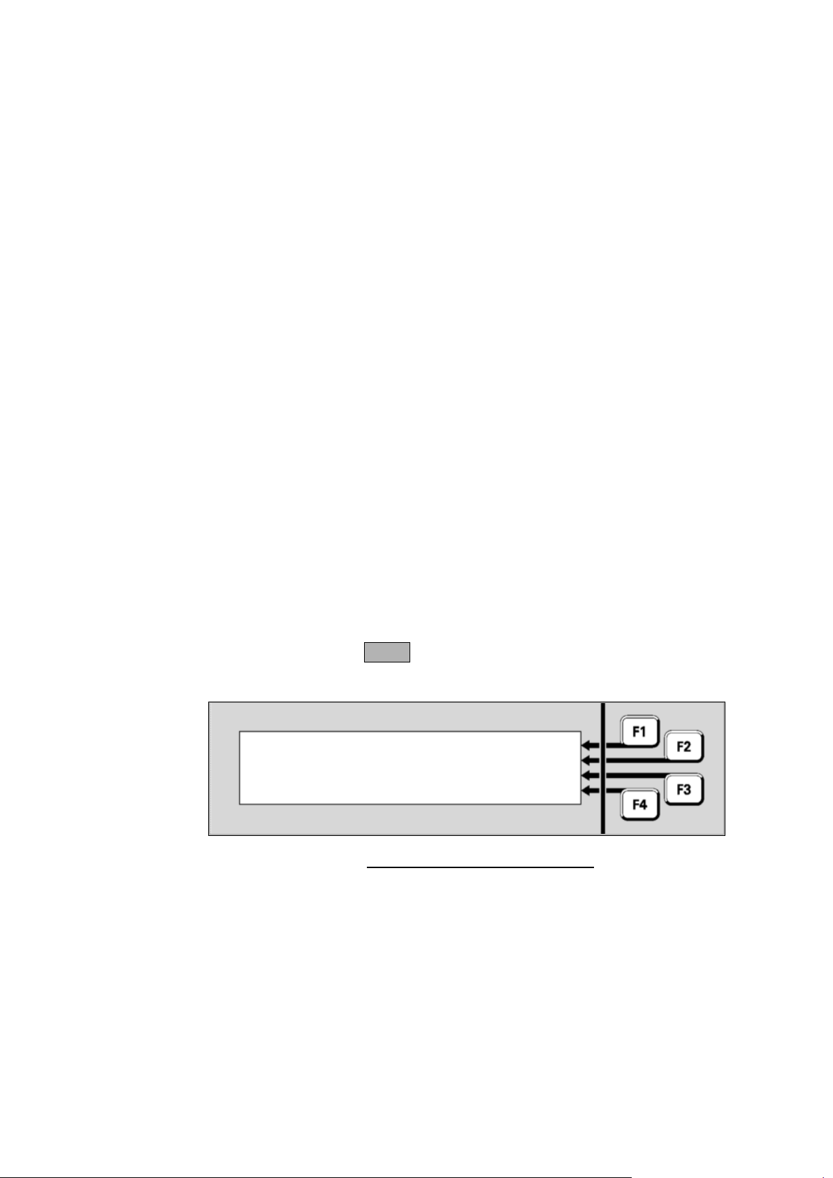
Document: LT0344 Vigilant MX1 Operator Manual
Equipment Numbers
Zones
P 1 . 1 .
0
MIM
800
MX Device
|
ENTER
Office
|
PREV
Normal
|
NEXT
|
MENU
Point command will disable all sub-points that can be disabled on device
address 1 on the in-built addressable loop. Some devices have only one
sub-point, thus commands to the device or its sub-point 0 have the same
effect.
Note that the MX1 treats entry of a device number as a range entry
covering all points on the specified device, thus menus will behave as if a
range had been entered and will not display point names.
Equipment numbers are:
1 – MX loop 1
2 onwards for additional MX loops (if fitted)
241 – MX Controller board points
242 – pseudo points – these are virtual points whose state can be
controlled by logic equations. These are usually used to produce
special operations in some installations.
243 – LCD/keyboard points
244 – RZDU/RDU points/equipment. If no RDUs have been enabled
in the site-specific configuration, these points cannot be viewed.
245 – points for additional MX loop cards (if fitted).
246 – Remote Fire Brigade Panel (FBP) points (if fitted).
247 – Network Status Points. Refer Chapter 9.
248 – Distributed Switch System(DSS) for AS 1668 fan controls.
Points for each control are not provided.
In the absence of any other information, a point can be found by entering
the first point in the particular equipment part (for example, entering 241
will bring up the first point on the controller board), and stepping through
the list of points with NEXT. The information displayed will assist in
identifying the desired point. For example;
A zone is a search area of a building or facility protected by the MX1 fire
alarm system. The limits of a zone are defined in NZS 4512. The zone
description is used by fire-fighters to quickly locate and respond to
alarms.
A zone represents one or more devices located within the zone area, and
the MX1 combines the states of the points representing these devices to
produce a common zone status indication for use by fire-fighters and
other emergency personnel.
Issue 2.4 8 August 2017 Page 1-15
Fig 1-3 – Example of Point Display
Page 24

Vigilant MX1 Operator Manual Document: LT0344
ISO Term
Equivalent industry term
Alarm
Fire
Fault
Defect
Disable/Enable
Isolate/De-isolate
c.i.e
Fire Indicator Panel (FIP)
Alarm/Fault Routing
Signals to remote receiving centre
ISO Terms Compared
A zone can have one or more of the following states:
Normal – this is the usual zone state, when all field devices are
operating normally, no tests are in progress and no other state is
present.
Pre-alarm – a detector mapped to the zone has gone into the pre-
alarm state.
FirstAlrm – for a Dual-hit zone. A device in the zone is in alarm,
but the zone itself is not yet in alarm.
Alarm – a device mapped to the zone has activated. Generally,
this calls the fire brigade.
Resetting – the zone is being reset.
Operate – output points mapped to the zone will be operated.
Fault – a device mapped to the zone is in the Fault state, or
Device Fail or Type Mismatch.
Disabled – the zone itself has been disabled by the operator to
prevent it from affecting system operation. Note that disabling all
points that map to the zone will automatically disable the zone as
well. In this case, at least one point must be enabled to allow the
zone to be enabled.
Test Operate – all outputs mapped to the zone will be operated
for testing purposes.
AutoReset –the zone is in Auto-Reset test mode.
AlarmTst – the zone is undergoing an alarm test.
AlTstFail – there has been an alarm test run on the zone that
failed. This state will clear after the next successful alarm test.
FltTest – the zone is undergoing a fault test.
For accessing a zone on another MX1 panel in a networked system, the
SID of the other panel is multiplied by 1000 and added to the zone
number. For example, to access zone 37 on an MX1 panel with a SID of
9 you would use the zone number 9037.
In general, this manual uses terminology taken from AS 7240.1 and
AS 7240.2. This table matches these with other common industry
terminology.
Note that when referring to the control of points and zones, “isolate” is
the term traditionally used in New Zealand and Australia, while the ISOstandard term “disable” is becoming more widely used.
Page 1-16 8 August 2017 Issue 2.4
Page 25

Document: LT0344 Vigilant MX1 Operator Manual
AVF
Alarm Verification Facility. A means by which the c.i.e. re-samples
the smoke detector to confirm smoke is still present.
Acknowledge
An operator action to record the indicated zone alarm has been seen,
for example, when handling AIF alarms.
Activated
This is the state of a point which is not in its "normal" or idle condition,
nor in fault. Examples are: a detector in alarm, a relay or LED turned
on, an input switch being closed.
Alarm
Devices
The devices used to warn the occupants within the protected
premises of an alarm. These include sounders, hooters, sirens,
occupant warning systems with speech, and may also include visual
indicating devices such as beacons or strobe lights.
Alarm List
The Alarm List is the list of current alarm conditions. When the Alarm
List is shown (as in the Quick Reference at the front of this manual)
the fire brigade panel controls function in accordance with the
requirements of NZS 4512.
Alarm
Routing
The transmission of an alarm condition to a remote monitoring centre
to summon the fire brigade.
The same transmission medium is often used to also transmit a fault
condition (Fault Routing) to the monitoring centre to summon a
service agent.
Auto-Reset
An in-situ detector test mode (sometimes called “Walk Test”), which
allows detectors to be alarm tested in their installed positions. The
zone is disabled and detector algorithms are bypassed to allow the
detector to go into alarm quickly. The detector is automatically reset
to allow the next detector in the zone to be tested.
Base Display
This is the display shown without operator intervention, or when the
CANCEL key has been held or pressed a number of times to get
back to the top display. The MX1 may be showing normal, faults,
disables. The Alarm List is a special base display (but is not classified
as the Base Display in this manual).
CO
Carbon Monoxide – a colourless poisonous gas that moves by
diffusion, emitted by smouldering fires.
Dirty
[detector]
Smoke detectors can become contaminated due to a buildup of dust,
dirt and other foreign particulates inside the sensing chamber. MX1
monitors the detector reading as it increases due to dirt buildup, and
compensates by shifting the alarm threshold to maintain a consistent
sensitivity to smoke. It signals a dirty state for the detector when this
reading indicates that the level of contamination is such that it can no
longer be compensated for.
From this point onward (until the detector is cleaned and replaced) it
is more sensitive to smoke and thus more likely to produce a
nuisance alarm.
FRC
Flat ribbon cables, usually internal to the c.i.e. cabinet.
Nuisance
alarm
An alarm condition that occurs without the presence of a fire.
Off-normal
(point)
The point is in a condition other than normal, for example fault,
disabled, active, etc.
Off-normal
(system)
A system condition where there is one or more points or zones that
are not normal. That is, a point or zone has a status other than
normal – for example, Fault, Alarm, Dirty, or Device Fail.
Residential
Mode
A configuration where a smoke detector alarm does not activate the
alarm devices and alarm routing. Only a warning local to the
originating detector is given.
General Terminology
Issue 2.4 8 August 2017 Page 1-17
Page 26

Vigilant MX1 Operator Manual Document: LT0344
Nuisance Alarms
Nuisance alarms (also called false alarms or unwanted alarms) are alarm
conditions caused by events other than a fire. These can be generally
categorised according to two causes:
The detector has correctly sensed the phenomena it is designed to
detect, but the reason for the phenomena being present is not a fire.
Examples are: a heat detector being triggered by very hot air from an
oven, hot outside air entering an air-conditioned foyer, smoke from an
outside fire triggering a smoke detector in the building, or welding
setting off a flame detector.
The detector has sensed a phenomenon different to what it is
designed to detect, but one that causes similar effects to the detector.
For example: steam or insects setting off a photoelectric detector,
dust from building works, a nail being driven through detector cabling,
or radio interference affecting a detector.
The actions to reduce the occurrence of both causes are generally the
same and involve:
Removing the unwanted effect that is causing the detector to
operate.
Repositioning the detector so it is not influenced by the effect.
Changing the settings of the detector so it is more resilient to the
effect.
Changing the detector type to one that is not sensitive to the effect,
but is still suitable for the environment and the risk.
Some precautions building owners/occupiers can take to reduce the
possibility of nuisance alarms include:
If structural repairs or maintenance are to be performed in the
building, ensure that any work that generates dust or smoke is only
carried out after the relevant zones have been disabled. Smoke
detectors should be fitted with temporary covers to prevent dirt from
accumulating. Once the work is complete, remove the covers, reset
any alarms detected while the zone was disabled, and then enable
the zone.
Ensure that kitchens, bathrooms, and shower rooms are fitted with
exhaust fans, and that if provided with closing doors there is pressure
relief to allow effective extraction when the doors are closed.
Page 1-18 8 August 2017 Issue 2.4
Page 27

Document: LT0344 Vigilant MX1 Operator Manual
Detectors should not be located where they can be exposed to dust,
heat or other phenomena that can adversely affect them. If they are
no longer in a suitable position or are not of a suitable type for the
location, contact the service company to discuss relocation or
changing the detector type.
If the building has long-term occupants, contact a reputable service
company to conduct training in how to minimise nuisance alarms.
Issue 2.4 8 August 2017 Page 1-19
Page 28

Page 29

Document: LT0344 Vigilant MX1 Operator Manual
Topic
See Page
Alarm Condition
2-1
Viewing Alarms
2-2
Resetting Zones in Alarm
2-4
Disabling Zones in Alarm
2-5
Alarms From Other Sources
2-5
Chapter 2
Managing Alarm Conditions
Alarm
Condition
In this Chapter
An alarm condition occurs when a fire detection device (such as a smoke
detector or manual call point) activates.
MX1 indicates the presence of the alarm condition by illuminating the
general FIRE indicator and zone indicators on the zone index, through
messages on the LCD, and (generally) by activating the building’s alarm
devices and alarm routing output to the fire brigade.
This chapter describes how MX1 displays alarms and how to use the
keypad to investigate and manage alarm conditions.
The alarms can be viewed on the LCD at Access Level 1. To reset or
disable alarms will require Access Level 2. See “Operator Access
Levels”, page 1-11, for more information.
Alarms from other sources, such as sprinkler systems, may be shown on
MX1. Refer to “Alarms From Other Sources” on page 2-5 for details.
In some installations smoke detector alarms may be programmed for
local annunciation only. This is called residential mode. Refer to page 26 for further information.
Refer to the page number listed in this table for information on a specific
topic.
Issue 2.4 8 August 2017 Page 2-1
Page 30
Vigilant MX1 Operator Manual Document: LT0344
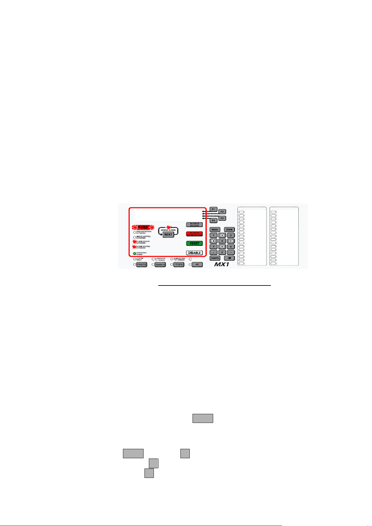
Smoke ALARM Z001 |MORE INFO
Reception | PREV
Atrium Entrance | NEXT
01 Zone Alarms Event 01 of 01 | ACK ALM
Viewing Alarms
What the MX1 Does When an Alarm Occurs
Alarm Display
When the first alarm condition is detected by the MX1, it does the
following to indicate the presence of the alarm:
The red general Fire indicators light red and individual Zone Alarm
indicators (if fitted) flash red.
The Fire Brigade alarm routing output is activated, shown by the red
ALARM ROUTING ACTIVATED indicator.
The Alarm devices are activated, shown by the red ALARM DEVICES
ACTIVATED indicator.
The Common Fire LED will be on.
Other outputs, e.g. smoke control, air-conditioning shutdown, door
holder releases, etc., may be activated to control the fire situation.
The LCD will show the detail of the first alarm.
Fig 2-1 – Example of an Alarm Display
The first line of each alarm will show:
o the alarm type (e.g., smoke, heat).
o the zone number alternating with the point number.
The second line of each alarm will show the zone name.
The third line of each alarm will show the point name.
The fourth line of each alarm will show:
o the number of zones in alarm.
o Which alarm event is displayed out of the total alarm events
present, as there may be multiple alarms per zone.
The SEVERAL ALARMS indicator will be lit if there are two or more
alarms present. Pressing the NEXT key will scroll the display through
any subsequent alarms (the alarm list).
In the Alarm Detail display, you can:
Press NEXT or NEXTF3 to step to the next (later) alarm,
Press PREVF2 to step to the previous (earlier) alarm,
Press ACKF4 (if enabled) to mark the alarm as acknowledged. The
acknowledgement time and date is recorded in the history log.
Page 2-2 8 August 2017 Issue 2.4
Page 31
Document: LT0344 Vigilant MX1 Operator Manual
This function requires Access Level 1.
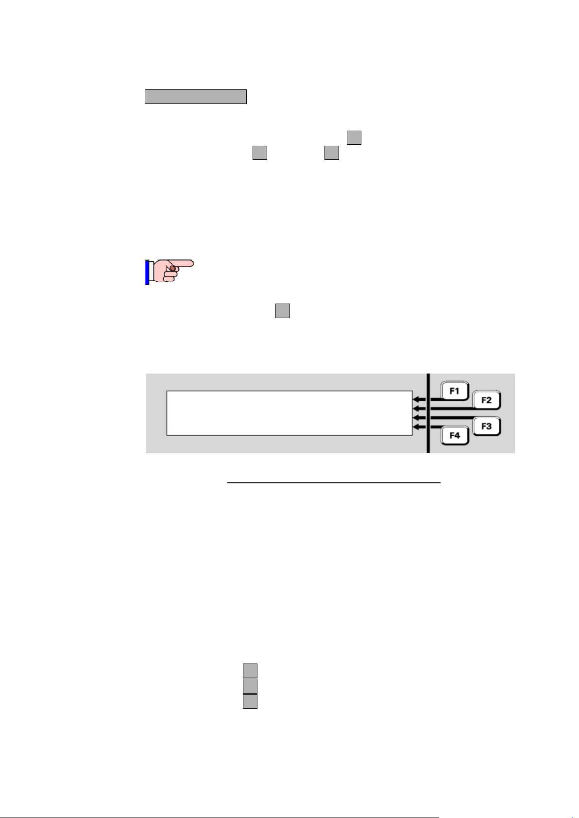
Smoke ALARM Z001|BACK
Confirm Mains Power Off |PREV
CL: 07.8 %m |NEXT
01 Zone Alarms 01:31:07 |ACK ALM
Silencing the Buzzer
Acknowledging Alarms
Viewing Additional Alarm Information
To silence the internal alarm buzzer in the MX1 cabinet, press the
SILENCE BUZZER key. This can be done at Access Level 1.
To acknowledge an alarm press ACKF4. If more than one device is in
alarm, press NEXTF3 or PREVF2, as described above, to step to the
next or previous alarm.
Acknowledging an alarm has the effect of indicating acknowledgement
on the LCD, may make any associated flashing zone alarm indicator go
on-steady and may also acknowledge the corresponding indication at a
remote display.
Pressing MORE INFO F1 will show the Alarm Additional Information
display for the particular alarm. NOTE if the panel sending the alarm is
not an MX1 panel then the information shown depends on the
configuration of the sending panel.
Fig 2-2 – Alarm Additional Information Display
The first line shows the alarm type and alternating zone and point
number.
The second line shows the zone action text.
The third line shows the current level (CL=”current analogue level”) in
appropriate units for the device type, in this example percent per metre
obscuration.
The fourth line shows the number of zones in alarm, and the time at
which this alarm occurred.
Press BACK F1 to return to the Alarm Detail screen.
Press NEXT F2 to step to the next (later) alarm.
Press PREV F2 to step to the previous (earlier) alarm.
Issue 2.4 8 August 2017 Page 2-3
Page 32

Vigilant MX1 Operator Manual Document: LT0344
In some circumstances, such as enabling a zone in alarm that
currently has no points in alarm or for a zone going into alarm
due to an alarm test, the alarm detail will show the first point
that put the zone into alarm.
This function requires Access Level 2.
Silence Alarms Keyswitch
Resetting Zones in Alarm
Overview
Resetting an Alarm
In NZ, silencing of the alarm devices is achieved with the Silence Alarms
keyswitch, for use by brigade staff.
This keyswitch requires a Bulgin key to operate. When this keyswitch is
operated:
all alarm devices are silenced,
new alarms will not re-sound the alarm devices,
the COMMON DEFECT and FAULTS indicators will be lit,
the key cannot be removed.
When the Silence Alarms keyswitch is restored to normal, all zones
currently in alarm will be automatically disabled. Refer to the next
section (“Resetting Zones in Alarm”) for instructions for resetting and
enabling these zones.
On a networked system the MX1 may be configured to allow you to
silence alarm devices on remote panels. Refer to Silencing Remote
Alarm Devices in Chapter 9.
Generally the alarm state latches within the MX1 so that each alarm can
be viewed later when fire-fighting personnel arrive at the fire panel.
When the alarms have been investigated and are no longer required they
can be reset.
The condition that caused each alarm must be cleared before the zone
can be reset to the normal state (for example, smoke cleared from smoke
detectors, manual call point element restored to normal).
If necessary, scroll the display with NEXT until the required zone alarm is
shown on the display.
Press RESET
Press OK to confirm the reset command.
While the alarm is being reset, “Resetting” will be shown on the LCD.
If the particular zone in alarm is reset successfully, all alarm entries for
that zone will disappear from the alarms list, the Zone Alarms will reduce
by one, and the Events count will reduce by the number of alarm entries
removed.
Page 2-4 8 August 2017 Issue 2.4
Page 33

Document: LT0344 Vigilant MX1 Operator Manual
This function requires Access Level 2.
If an Alarm will not reset
Disabling Zones in Alarm
Overview
Disabling an Individual Alarm
Enabling Disabled Zones
Alarms From Other Sources
If one or more detectors or devices in the zone are still active, the zone
alarm state will not reset. At the end of the reset period, any points still in
the alarm condition will be re-annunciated as new alarms.
Disabling a zone stops the zone’s state from affecting the system.
When a zone is disabled, it cannot put the system into alarm or fault, nor
can an existing alarm or fault on the zone cause outputs to operate.
If necessary, scroll the display with NEXT until the required zone alarm is
shown on the display.
Press DISABLE.
Press OK to confirm the disable command.
When the particular zone is disabled, all alarm entries for that zone will
disappear from the alarms list, the Zone Alarm count will reduce by one,
and the Events count will be reduced by the number of entries removed.
Refer to Chapter 3, “Managing Faults and Disables”, for details on how
to enable zones that have been disabled.
Other alarm types, such as sprinkler systems, pump run status, etc., may
be connected to the MX1 and displayed in a number of ways.
The sprinkler system will normally activate the alarm routing and alarm
devices independently of the MX1, but use the MX1 to simply indicate
that the sprinkler system has operated and may also show which flow
switches are operating within the building. These indications will usually
not be alarm conditions and will clear automatically when the water flow
is stopped.
Issue 2.4 8 August 2017 Page 2-5
Page 34

Vigilant MX1 Operator Manual Document: LT0344
Residential Mode
The MX1 may be configured for some smoke detectors to work in
residential mode (often used in permanently occupied apartments where
the occupant can take action if smoke is indicated). An alarm on such a
detector will not summon the Fire Brigade but a local alarm is given at
the detector (for example, by a sounder base) so that the occupant(s)
can investigate the situation and determine whether there is a fire.
If the situation is found to be a real fire, a general alarm can be
generated by activating a manual call point, usually in a common area. If
the detector is a combined smoke and heat multi-sensor, an alarm from
the heat sensor will generate a general alarm.
Residential mode can include annunciation of a smoke detector alarm at
a reception desk, for example.
If the situation is found to not be a real file (for example toast
overheating), the local alarm will normally be able to be cancelled by
operating a pushbutton within the local area.
Page 2-6 8 August 2017 Issue 2.4
Page 35

Document: LT0344 Vigilant MX1 Operator Manual
Generally, all faults are signalled to the fault routing
equipment.
MX1 uses non-volatile memory to store the disable status for
zones, points, ancillary groups and the alarm devices. If the
MX1 is powered down or restarted within 10 seconds of
disabling or enabling a zone, point, etc., then the new status
may not be stored correctly and the old status will remain.
Chapter 3
Managing Faults and Disables
Fault Conditions
Disabled Conditions
Other OffNormal
Conditions
A fault condition occurs when a system component is in a condition that
may affect its ability to function correctly.
The MX1 continually checks the condition of its internal and external
components, and will generate indications on the front panel and signals
to the fault routing equipment, etc., when it detects a fault.
Examples of faults are:
an MX detector is removed from its base,
a field wiring problem (open circuit, short circuit or signal interruption)
between the MX1 and any of its detectors,
a ground fault between MX1 wiring and earth,
a problem with the power supply or battery.
A disabled condition occurs when an operator takes a component out of
service, for example, to prevent a nuisance alarm when maintenance
work such as building repairs or welding is being done in an area, or
because it is faulty and repair may take some time.
A disabled component is prevented from contributing to alarm and fault
indications or outputs. However, since the system is not in a “normal”
state, under most configurations the presence of disabled components is
shown by indications on the front panel.
The LCD will display a message “SYSTEM IS OFF-NORMAL” when any
points are off-normal, but not in alarm or fault. This could be due to a
service error such as:
Alarm routing is isolated,
Database Write Enable link is fitted, etc.
Pressing the NEXT key will display any of-normal points.
The Common Normal (Green) LED will be on if there are no off-normal
Issue 2.4 8 August 2017 Page 3-1
conditions, no faults, and no alarms.
Page 36
Vigilant MX1 Operator Manual Document: LT0344
Topic
See Page
Viewing Faults
3-2
Viewing Disables
3-4
Disable Menu Options
3-6
In this Chapter
Viewing Faults
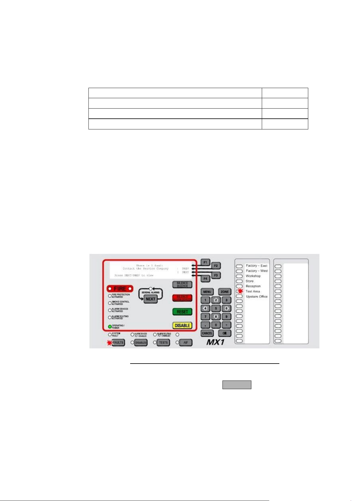
How the MX1 Indicates the Presence of a Fault
Responding to a Fault Indication
This chapter describes using the operator interface to investigate the
details of a fault condition, and to manage disables.
Refer to the page number listed in the following table for information on a
specific topic.
When a fault condition that has not been disabled is detected by the
MX1, the operator interface does the following:
The Common Defect LED will be on.
The yellow FAULTS indicator lights.
If fitted, a yellow zone indicator will flash for a zone fault.
The buzzer sounds continuously (if configured, e.g., local mode
panels).
The LCD displays the number of fault conditions present and may
show a fault action message, for example to call the service
company, as shown below:
Fig 3-1 – Operator Interface Showing Fault Condition
If a fault condition occurs on a disabled item then no indication is given,
but the fault(s) can be viewed by pressing FAULTS.
Faults should be assessed and repaired only by a trained and competent
operator. Otherwise, the service company should be called. Chapter 10
contains a fault finding guide.
Page 3-2 8 August 2017 Issue 2.4
Page 37
Document: LT0344 Vigilant MX1 Operator Manual
This function requires Access Level 2.
Zone 006 Std Detection G1 | DISABLE
Test Area | PREV
| NEXT
Fault | MENU
Viewing the Fault Details
Zone Faults
Point Faults
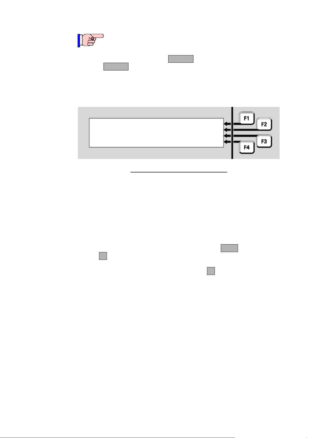
If the Faults indicator is lit, press FAULTS to display the first item in fault.
Pressing FAULTS will work from most displays as well as the base
display.
Any zones in fault are listed first, in numerical order, followed by the
points in fault, also in numerical order.
Fig 3-2 –
MX1
LCD Showing Zone Fault
“Zone 006” indicates the zone in which the fault condition has arisen.
The Profile name displayed (Std Detection G1 in this example) identifies
the set of configuration settings in use for the zone.
“Test Area” indicates the location text for the zone.
The bottom two lines show the status conditions present for the zone.
To step the Fault display to the next item, press the NEXT key or
NEXTF3 soft key.
To step to the previous item, press the PREVF2 soft key.
A zone fault will be registered only if one of the points associated with
that zone is or was in a fault condition.
Zones can be configured to latch their faults, i.e., to maintain the fault
indication even after the point fault that originally caused it has cleared.
A point fault will be indicated if the point has a fault condition present.
This could be a wiring or supervision fault, an addressing fault or some
other detected mis-operation.
In some instances a fault on a device will put all of the points of that
device into the fault state, for example Device Fail and Type Mismatch
faults. Thus a single device fault may result in more than one fault being
Issue 2.4 8 August 2017 Page 3-3
Page 38

Vigilant MX1 Operator Manual Document: LT0344
This function requires Access Level 2.
For NZ systems most faults do not latch, and so clear when
the cause is removed.
Resetting a Displayed Fault Indication
Viewing Disables
How the MX1 Indicates the Presence of Disabled Items
indicated on the system. However, events for only point 0 will be logged
to the event history or to the printer, so as to not unnecessarily fill the
event history.
Fault indications for points are usually non-latching, i.e., when the point
fault is cleared, the fault indication will automatically clear.
Therefore, while it is usual to find zones and points in the Faults list, it is
possible to find only zones in the list, if all the point faults have cleared.
In this situation, the point that caused the zone fault can be determined
from the history log. See Chapter 4, Viewing the Event History.
To reset a latched fault indication:
Press FAULTS to display the Fault detail display.
Press NEXT or PREVF2 to step through the Fault list to the zone or
point to be reset.
Press RESET and OK to confirm the reset.
If the reset was successful, the state of the zone or point will change from
Fault to Normal. If the fault is still present, the fault indication will not
clear, or may clear and re-announce after a few seconds.
If the fault on a zone does not clear then the fault condition is still present
on one or more points, and these point faults will need to be cleared
before the zone fault can be reset.
When there are one or more zones, points or components that have
been disabled, the operator interface does the following:
The yellow DISABLES status indicator lights.
If fitted, the yellow zone indicator will turn on for a disabled zone.
The LCD on the interface panel indicates the presence of an Off-
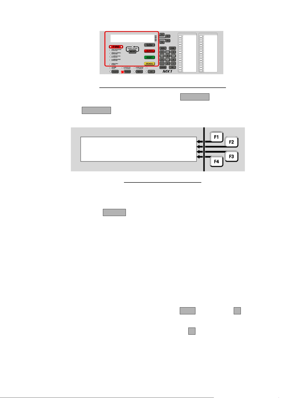
Normal condition, as shown below.
Page 3-4 8 August 2017 Issue 2.4
Page 39
Document: LT0344 Vigilant MX1 Operator Manual
Vigilant MX1
Site Name
MX1 V1.34 NZS 4512:2003 09:48:27
System is off-normal 15/01/10
Zone 001 Std Detection G1 | ENABLE
Office | PREV
| NEXT
Fault Disabled | MENU
Viewing the Disabled Items
Fig 3-3 – Operator Interface Showing Disables Condition
To view the list of disabled items, press the DISABLES key.
The DISABLES key will work from most displays as well as the base
display. This will show the first item in the Disables list.
In the example here, zone 001 has a fault as well as being disabled, but
the Disabled condition means that this will not produce a Fault indication.
However, it will still appear in the list of items that can be viewed by
pressing the FAULTS key. Similarly disabled zones in alarm will indicate
the alarm status when the Disables key is pressed.
Disabling a zone is a convenient way of hiding the state of all the points
associated with that zone. However, the points themselves are not
disabled by disabling the zone and may still affect other zones or outputs
that they are mapped to.
Note that the disabled point or zone may have other conditions present
(fault, alarm, etc.), but that these indications are prevented from affecting
the system by the point or zone being disabled.
The disabled zones are listed first, in numerical order, followed by the
disabled points, also in numerical order.
To step through the Disables list, press the NEXT key or NEXTF3 soft
key.
To step to the previous item, press the PREVF2 soft key.
If there are no disabled items in the list, the display shows “no disables
found” and then changes to the “Disable” menu. See page 3-6, “Disable
Issue 2.4 8 August 2017 Page 3-5
Menu Options”.
Fig 3-4 – Viewing the Disables List
Page 40
Vigilant MX1 Operator Manual Document: LT0344
This function requires Access Level 2.
If the disabled zone or point is in Alarm, enabling it may
cause the system to enter the Alarm state.
This function requires Access Level 2.
Do not press the f.b.p DISABLE key when the Alarm List is
being shown unless the intent is to disable the displayed
zone in alarm.
Select item to disable or | ZONE
enable | POINT
|ALRM DEV
| ANCILS
Enabling a Disabled Item
Disable Menu Options
To enable a disabled item:
Press DISABLES to display the Disables list.
Step through the Disables list with NEXTF3 or PREVF2 to the
zone or point to be enabled.
Press DISABLE or ENABLEF1 and then OK to confirm the enabling.
From the Disables List other options are available by pressing the MENU
key. These are described in the next section.
There are commands available from the Disable menu to disable or
enable whole blocks of zones or points as well as individual zones or
points.
Press the DISABLE key from the base display. Alternatively, from the
Disables List, press the MENU F4 option. This gives a menu of what to
disable or enable.
Fig 3-5 – Selecting an Item to be Disabled or Enabled
ZONEF1 allows a zone or range of zones to be enabled/disabled.
Refer to Disabling or Enabling a Zone (page 6-10).
Page 3-6 8 August 2017 Issue 2.4
POINTF2 allows a point or range of points to be enabled/disabled.
Page 41

Document: LT0344 Vigilant MX1 Operator Manual
This function requires Access Level 2.
This function requires Access Level 2.
To activate the internal Silence Alarms function, press the
SILENCE/RESOUND ALARMS key.
The yellow ALARM DEVICES DISABLED indicator will light and the
alarm devices will be switched off, if they were on.
This function requires Access Level 2.
To cancel the internal Silence Alarms function, press the
SILENCE/RESOUND ALARMS key again. The MX1 will ask for
confirmation of this action if the alarm devices will then turn on.
Press OK to confirm.
The yellow ALARM DEVICES DISABLED indicator will go out, as well
as the DISABLES indicator if there are no other disables present.
This function requires Access Level 2.
Alarm Devices
Internal Silence Alarms
Cancelling Internal Silence Alarms
Ancillary Groups
Refer to Disabling or Enabling a range of Points (page 6-7).
ALRM DEVF3 allows the Alarm Devices to be enabled/disabled.
ANCILSF4 allows the ancillary groups to be enabled/disabled (see
page 3-7).
From the Disable Menu press ALRM DEVF3 to enable/disable the
alarm devices. The confirmation screen will show the action that is about
to be performed (i.e., enable or disable) and request the OK key be
pressed.
If OK is pressed the action is carried out, otherwise press CANCEL to
return to the previous screen.
This function is the same as the Internal Silence Alarms function – see
below.
Many MX1 installations have functionality for control of lifts, air-
Issue 2.4 8 August 2017 Page 3-7
conditioning systems and so forth during alarm conditions. When the
panel is undergoing tests it may be necessary to disable this functionality
in order to avoid disruption to site occupants.
Page 42
Vigilant MX1 Operator Manual Document: LT0344
0:Ancil Group 0 Enabled| DISABLE
1:Ancil Group 1 Enabled| DISABLE
2:Ancil Group 2 Enabled| DISABLE
3:Printer Output Enabled| DISABLE
The Disable Ancils command provides a convenient means to enable or
disable this functionality without having to address each individual
function.
From the Disable menu press ANCILSF4. This gives a display such
as follows.
Fig 3-6 – Ancillary Groups Display
Each line represents one ancillary group and gives a description of the
functionality controlled by that group, followed by its status (Enabled or
Disabled). Each group can be enabled or disabled by pressing the
corresponding F-key. No confirmation is required.
The functionality represented by each ancillary group is determined by
the site-specific configuration. The names of the ancillary groups should
describe this functionality. In the above example, “Printer Output” is one
such description.
Note that if no functionality has been configured for an ancillary group,
disabling that group will have no effect on the system but could result in
the DISABLES status indicator turning on (as each Ancillary Group has a
point that reflects its Enable/Disable status and these appear in the
Disables list when the group is disabled).
Page 3-8 8 August 2017 Issue 2.4
Page 43
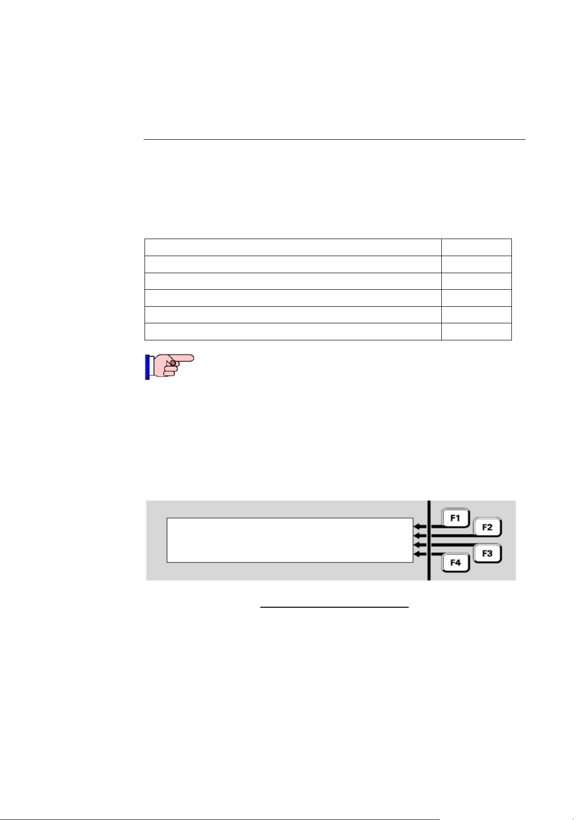
Document: LT0344 Vigilant MX1 Operator Manual
Topic
See Page
General Message Format
4-1
Viewing Event History
4-2
Zone Events
4-3
Point Events
4-5
System Events
4-6
When contacting technical support services, ensure that the
event message shown on the MX1 LCD is quoted exactly as
shown.
09:23:11 15/01/10 | OLDEST
Point 241.1.0 | PREV
Enabled | NEXT
Alarm Alerting Devices | NEWEST
Chapter 4
Viewing the Event History
Introduction
In this Chapter
General Message Format
The MX1 maintains a history of the 900 most recent events that have
occurred. These are stored in non-volatile memory, so are not lost on
power down. When the history is full, the oldest event is deleted so a
new event can be added.
Each message in the Event History shows a change in the state of some
system component, for example a zone or a point. The message shows
the new state, the component that changed, and the time and date when
the change was registered.
Fig 4-1 – Event History Message
In this example, the message is saying that at 9:23:11 am on 15th
January 2010, the point numbered 241.1.0, representing the Alarm
Devices, was enabled.
There are three types of event message:
System, where line 2 of the display says “Local event”
Zones, where line 2 of the display says “Zone nnn”
Points, where line 2 of the display says “Point Eq.Dev.Sub”.
Issue 2.4 8 August 2017 Page 4-1
The following sections describe these in more detail.
Page 44
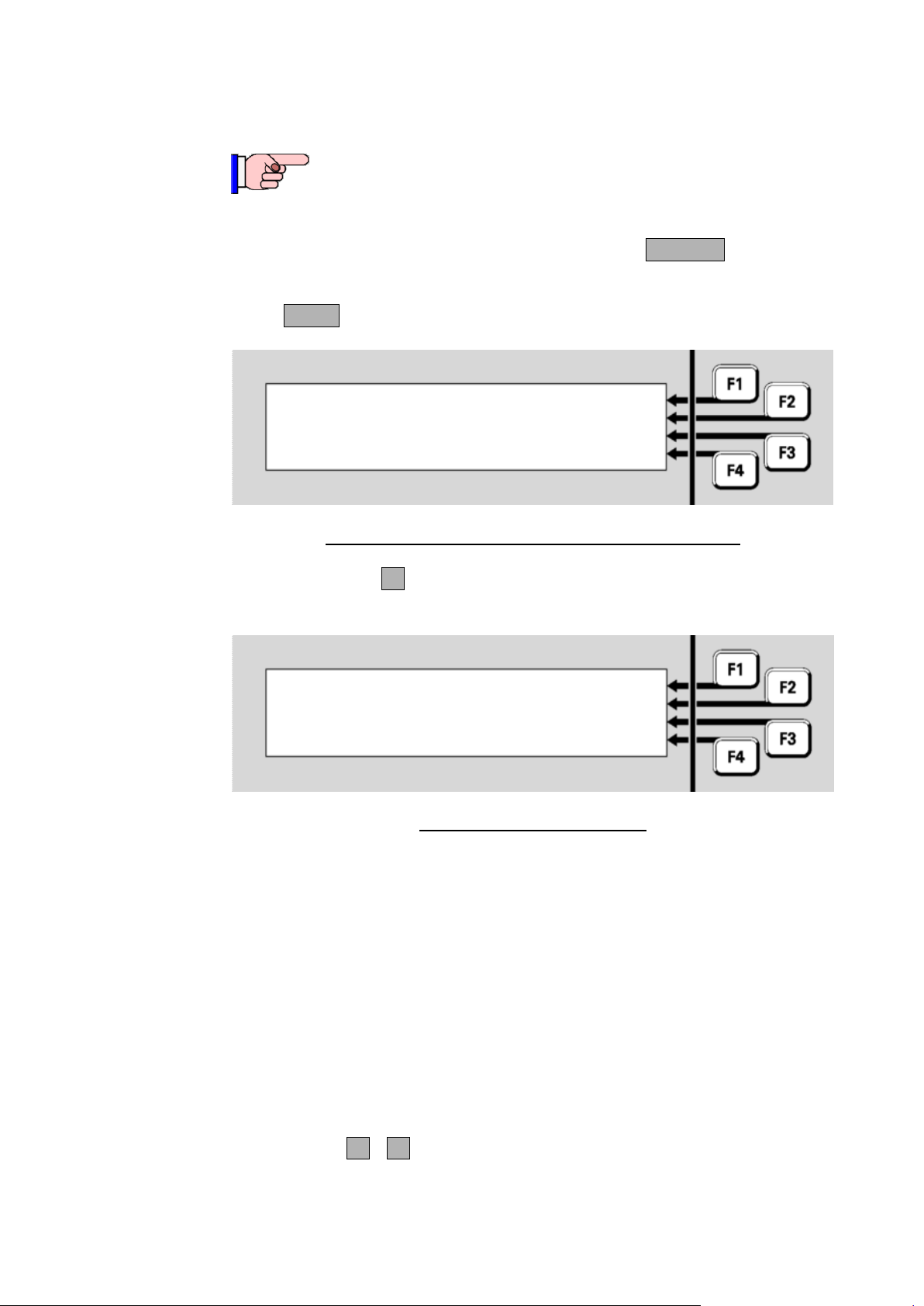
Vigilant MX1 Operator Manual Document: LT0344
This function requires Access Level 2.
|DISP TST
| RECALL
| HISTORY
Press MENU for more options | POWER
06:35:42 07/07/07 | OLDEST
Point 241.1.0 | PREV
Enable | NEXT
Alarm Devices | NEWEST
Displaying Event History
Viewing Event History
If the MX1 display is not showing one of the base displays, i.e., Normal,
Off-Normal, Fault or the Alarm list, press and hold CANCEL until the
current base display is shown.
Press MENU to see a set of options:
Fig 4-2 – Options Resulting from Pressing the Menu Key
Press HISTORYF3 to display the event history. The most recent event
will be displayed first.
Fig 4-3 – Event History Display
The display shows:
the time and date of the event,
the number of the zone or point, or “Local Event” for system events,
the type of event, e.g., Disable, Enable, Alarm, Fault, or a description
of the local event,
the text description of the zone or point involved.
Explanations of the event messages are given below.
Descriptions of the MX1 controller and other equipment points are in
Section 11.
The soft keys F1 - F4 are used to step forward and backward through
the event log:
Page 4-2 8 August 2017 Issue 2.4
Page 45
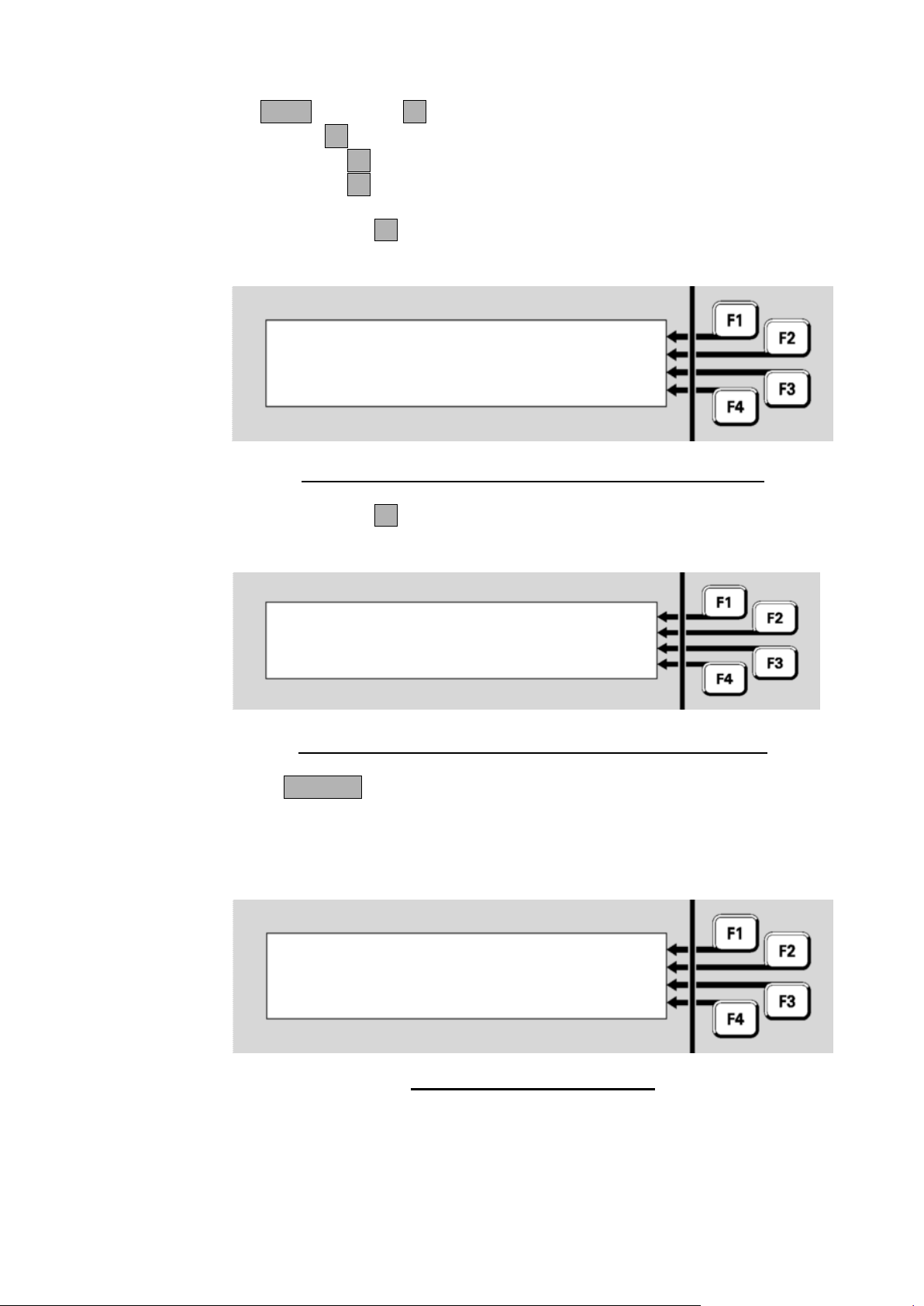
Document: LT0344 Vigilant MX1 Operator Manual
| OLDEST
Next is oldest | PREV
| NEXT
| NEWEST
| OLDEST
Previous is newest | PREV
| NEXT
| NEWEST
<time> <date>
Zone <n> | PREV
<event text> | NEXT
| NEWEST
| OLDEST
<zone text>
History Navigation Keys
Zone Events
NEXT or NEXTF3 steps to the next (later) event.
PREVF2 steps to the previous (earlier) event.
OLDESTF1 shows the oldest event in the log.
NEWESTF4 shows the newest (most recent) event.
Stepping NEXTF3 from the newest event will return to the oldest event
after a brief message.
Fig 4-4 – Brief Message Shown Before Displaying Oldest Event
Stepping PREVF2 from the oldest event will return to the newest event
after a similar message.
Fig 4-5 – Brief Message Shown Before Displaying Newest Event
Press CANCEL to return to the base display.
Fig 4-6 – Zone Event Text Format
Issue 2.4 8 August 2017 Page 4-3
Page 46

Vigilant MX1 Operator Manual Document: LT0344
Zone Events Text
Event Text
Meaning
Activate
This zone has become Active (distinct from Alarm
state). Output points mapped to the zone become
operated.
Alarm
One or more of the detectors in this zone has gone into
Alarm.
Alarm ACK'D
The alarm on this zone has been acknowledged by a
user.
Alarm clear
The alarm on this zone has cleared.
Alarm Test
Start
A test of the processing of alarm conditions in this zone
has been started.
Auto Disable
This zone has been automatically disabled/ isolated, for
example following operation and restoration of the NZ
Silence Alarms keyswitch.
Auto Reset Test
Auto-Reset mode has been started for this zone.
Auto Reset
Timeout
Auto-Reset mode for this zone has been cancelled due
to a timeout period with no new alarms.
Bad Event
The event code wasn’t recognised by this panel.
Deactivate
This zone has stopped being Active.
De-operate
All output devices in this zone have been switched out
of the operated condition.
Disable/Enable
This zone has been disabled/enabled by an operator
command respectively.
Fault
One or more of the devices in this zone is faulty.
Fault clear
All faults on this zone have cleared.
Fault Test
Start
A test of the processing of fault conditions in this zone
has been started.
Fault Test Stop
A fault test has been terminated by an operator.
First alarm
A detector mapped to this zone has signalled alarm,
but the zone alarm is not signalled yet because the
alarm is being investigated (AAF alarm) or a second
point in alarm is required (the zone is programmed for
dual-hit operation).
Input activated
Input
deactivated
An input point mapped to this zone has become Active
(distinct from Alarm) or has stopped being Active,
respectively.
Normal
This zone has returned to normal.
Operate
One or more non-disabled output devices in this zone
have been switched into the operated condition.
Operate Test
Start
An Operate Test command has been issued for this
zone. This will result in all the zone’s output points
being test-operated.
Pre-alarm
One or more of the detectors in this zone is in a prealarm condition.
Pre-Alarm clear
The pre-alarm condition on this zone has cleared.
Reset
This zone has been reset by an operator command.
Test Abort
The current test on this zone has been cancelled.
Test Fail
The current test on this zone has failed.
Test Pass
The current test on this zone has passed.
The <zone text> is the descriptive text for the zone.
The <event text> is one of the following:
Page 4-4 8 August 2017 Issue 2.4
Page 47

Document: LT0344 Vigilant MX1 Operator Manual
<time> <date>
Point <n> | PREV
<event text> | NEXT
| NEWEST
| OLDEST
<point text>
Point Events Text
Event Text
Meaning
Alarm
This point is in alarm.
Alarm Clr
The alarm condition on this point has cleared.
Alarm test fail
This point has failed its alarm test.
Alarm test start
An alarm test on this point has started or stopped, respectively.
Alarm test stop
Auto-Reset start
Auto-Reset mode for this point (detector) has been started or
stopped, respectively.
Auto-Reset stop
Control CB Fail
This relay output point will not switch to its required state. The
checkback signal does not match the required state.
Control CB Nml
This relay output point is now in its required state.
De-operate
The output device has been switched out of an operated.
Device Fail
This point (MX addressable device) is not responding to polling
requests from the MX1.
Device Fail Clear
This point (addressable device) is now responding to polling
requests.
Device Fault
This flame detector has a fault other than a window fault.
Dirty Alert
This point (detector) is still functional but requires service due to
contamination.
Dirty Alert Clr
This point (detector) is no longer affected by contamination.
Disable
This point has been disabled.
Enable
This point has been enabled.
Fault
This point is faulty.
Fault Clr
The fault condition on this point has cleared.
Input activated
An input device has changed into or out of an activated condition,
respectively.
Input deactivated
Load Supply Fail
The separate supply to this device, for example a DIM800 or
SNM800, is faulty.
Low Temp Fault
The ambient temperature for a detector with a CO sensor has gone
below (above) its long term minimum operating limit.
Low Temp Normal
O/C Fault
An input or output has an open circuit in the wiring connected to it.
Old MX ASIC Fault
The MX module does not support the requested function (e.g., falling
edge interrupts) so needs to be replaced with a newer model.
Isolator Fault
The line isolator of the MX device is activated due to a short circuit
condition on the MX loop. Only some devices will report this.
Operate
The output device has been switched into an operated.
Parameter Error
This device has been incorrectly set up at the factory and requires
replacement.
Point Type
Mismatch
The reported and configured types differ for this MX point.
Point Type OK
The reported and configured types now agree for this point.
Pre-Alarm
This detector has gone into a pre-alarm condition.
Pre-Alarm clear
The pre-alarm condition on this point (detector) has cleared.
Reset
The point has been reset, clearing any latched state.
Point Events
Fig 4-7 – Point Event Message Format
The <point text> is the configured descriptive text for this point.
The <event text> is one of the following:
Issue 2.4 8 August 2017 Page 4-5
Page 48
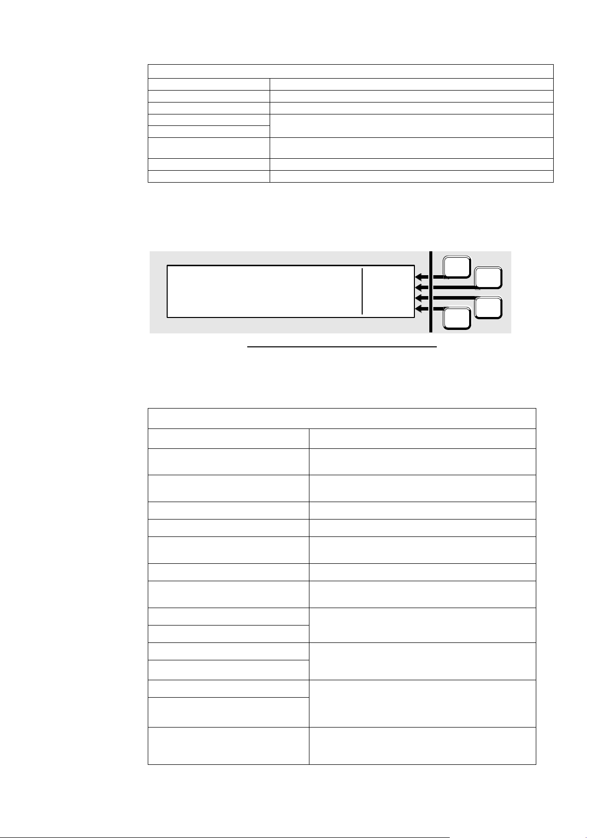
Vigilant MX1 Operator Manual Document: LT0344
Point Events Text
Reset history
The point’s HH and HL values have been reset.
Reset tracking
The point’s TV value has been reset (to the CV).
S/C Fault
An input or output has an short circuit in the wiring connected to it.
Test De-operate
This output point has been switched into or out of an operated
condition as part of a point test.
Test Operate
Test Start Not nml
This point is not Normal at the start of a self test, for example type
mismatch, device fail.
Unassigned point
There is a device at this address which is not in the system data file.
Window Fault
This flame detector has a dirty window.
F1
F2
F4
F3
<time> <date> OLDEST
Local event PREV
<event text> NEXT
NEWEST
System Events Text
Event Text
Meaning
Alarm Devices Silence
The alarm devices were silenced after an alarm
occurred.
Alarm Devices Unsilence
The alarm devices were resounded after being
silenced.
Bad Event
The event code was not recognised by the panel.
Cold start
The MX1 has been powered up.
Command Received
A zone or point command has been received on the
network from the specified SID.
Commission Mode On/Off
Commissioning mode has been started/stopped.
Date changed
The system date has been changed. The new date is
used for the event.
Daylight Save Start
Daylight Saving Time adjustment to the system clock
has been started or stopped, respectively.
Daylight Saving End
DB Prgrm (ID) User Name
A user able to change the system datafile logged on
or logged off the programming port, respectively. ID is
user ID, user name shows the user’s name.
DB Prgrm end
Diag logon (ID) User Name
A user able to use diagnostic functions logged on or
logged off the diagnostic/programming port,
respectively. ID is user ID, user name shows the
user’s name.
Diag logoff
History Reset
Non-volatile event messages were all cleared (usually
following a restore failure). All previous history events
will have been lost.
System Events
Fig 4-8 – System Event Message Format
The <event text> is one of the following:
Page 4-6 8 August 2017 Issue 2.4
Page 49

Document: LT0344 Vigilant MX1 Operator Manual
System Events Text
History restore fail
Retrieval of non-volatile event messages failed during
system start up.
Keypad restart
The LCD/Keyboard microprocessor has restarted.
LCD logon
A user able to use Level 3 functions logged on or
logged off, respectively.
LCD logoff
Logic vars reset
The values of non-volatile logic variables were reset
(usually following a restore failure). All nonvolatile
variables will be initialised to FALSE.
Logic vars restore fail
Retrieval of non-volatile logic variables failed during
start up.
Pnt disables reset
Non-volatile point disable states were reset (usually
following a restore failure). All points will have
become ENABLED.
Pnt disables restore fail
Retrieval of non-volatile point disable states failed
during start up.
Printer events lost
The printer queue was over filled, so some events to
be printed were lost.
Reboot xxx yyyyyyyy
The MX1 internal checking routines have detected an
inconsistency that needs to be addressed. Xxx,
yyyyyyyy show the details of the fault. If this occurs
repeatedly contact your service company.
RZDU Cmd rec'vd
An operator command was received from a connected
RZDU.
RZDU test timeout
An RZDU failed to report that a self-test passed within
4 minutes of starting.
Sw fault xxx yyyyyyyy
The MX1 internal checking routines have detected an
inconsistency that needs to be addressed.
xxx,yyyyyyyy show the details of the faults. If this
occurs contact your service company.
System running
This is a daily timestamp, indicating the system is
working.
TAP Access Granted
A temporary access password has been used to log
onto the MX1.
Time changed
The system time has been changed. The new time is
used for the event.
Warm start
The MX1 has restarted without being powered down,
for example, to change the datafile.
Zone disables reset
Non-volatile zone disable states were reset (usually
following a restore failure). All zones will have
become ENABLED.
Zn disables restore fail
Retrieval of non-volatile zone disable states failed
during start up.
Issue 2.4 8 August 2017 Page 4-7
Page 50

Page 51

Document: LT0344 Vigilant MX1 Operator Manual
Topic
See Page
Recall Menu Options
5-2
Recalling Off-Normal Points and Zones
5-3
Using the Zone Button to Recall Points and Zones
5-8
Chapter 5
Recalling Zone and Point Status
Introduction
In this Chapter
This chapter describes using the front panel to view the status of zones
and points.
The various states that zones and points can have are described on
pages 1-12 and 1-15 respectively.
Note; some points may be recallable and appear to be in various
“normal” states, but cannot have commands performed upon them. This
may be due to the configuration settings used in a particular MX1
installation, or that the points are for display-only purposes.
Equipment Points are listed on page 11-2.
Refer to the page number listed in this table for information on a specific
topic.
Issue 2.4 8 August 2017 Page 5-1
Page 52
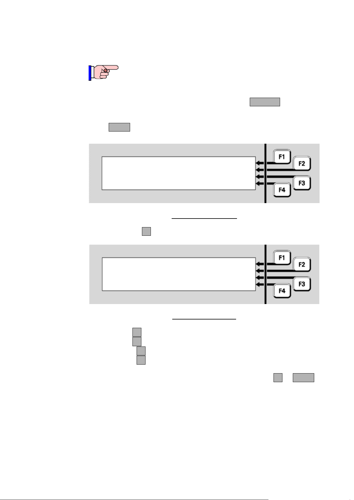
Vigilant MX1 Operator Manual Document: LT0344
This function requires Access Level 2.
|DISP TST
| RECALL
| HISTORY
Press MENU for more options | POWER
Requirements
Recall Menu Options
Select what to recall
|
POINTS
|
ZONES
|
ALL PTS
|
ALL ZNS
If the MX1 display is not showing one of the base displays, i.e., Normal,
Off-Normal, Fault or the Alarm List, press and hold CANCEL until the
base display is reached.
Press MENU (or from the Alarm List press TECHMENU-F4) to see a set
of options:
Press RECALLF2 to select what to recall.
Press:
POINTSF1 to show the off-normal points recall options
ZONES F2 to show the off-normal zones recall options
ALL PTSF3 to show the state of all points
ALL ZNSF4 to show the state of all zones.
In the subsequent point or zone displays, pressing MENUF4 or MENU
displays a menu of commands that may be applied to the zone or point.
These are described in Chapter 6, ”Zone and Point Functions”.
Note: some points may be programmed to be excluded from off-normal
or fault displays because they are not used in a particular MX1
installation. Therefore, these will never appear in the Faults list or the
Off-Normal Points list. However, they may be programmed to appear in
the All Points list, and may show a state other than Normal. Some points
may be programmed to never be displayed, and these points will not
Page 5-2 8 August 2017 Issue 2.4
appear in any of the lists.
Fig 5-1 – Menu Options
Fig 5-2 – Recalls Menu
Page 53
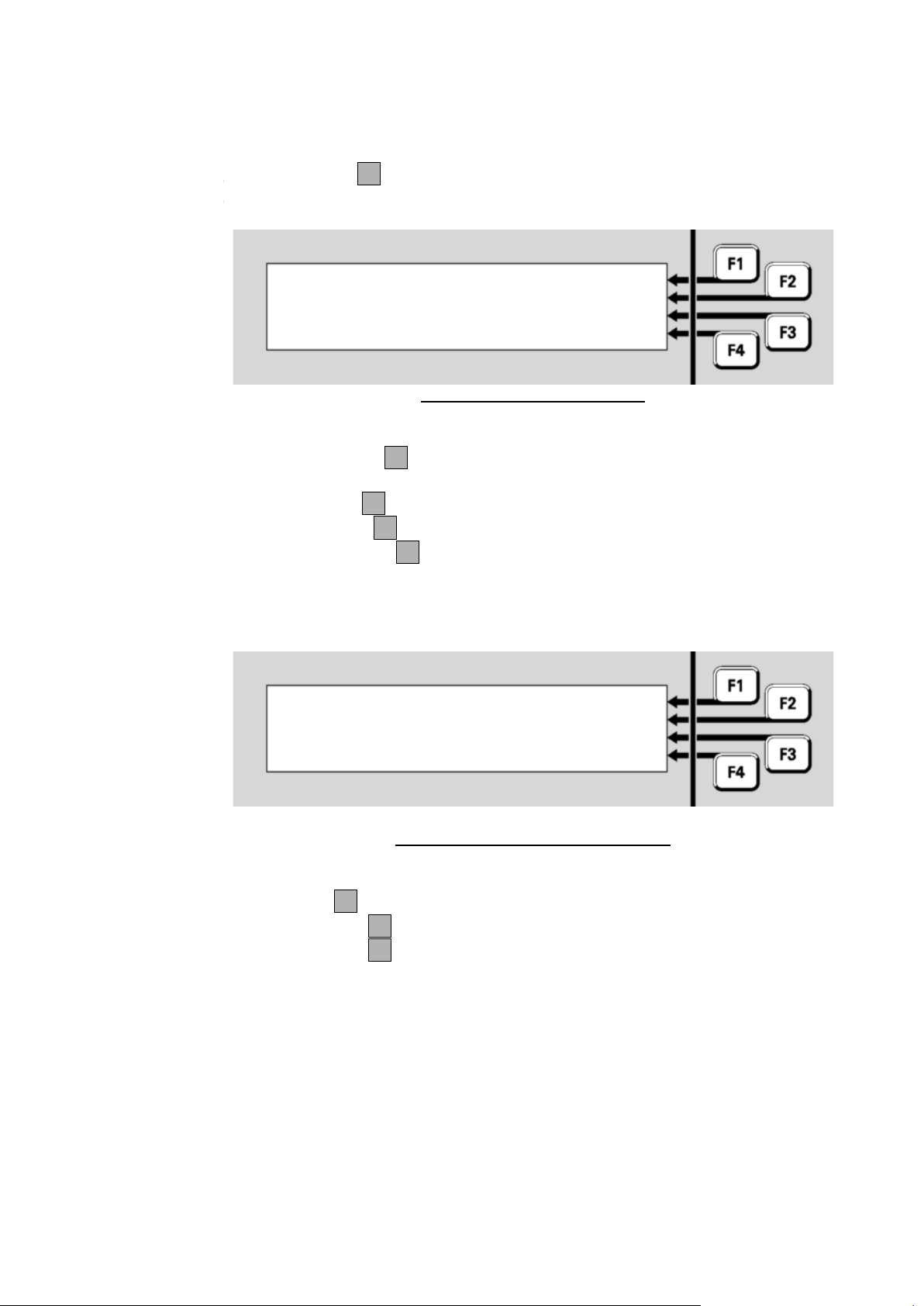
Document: LT0344 Vigilant MX1 Operator Manual
Recalling Off-Normal Points and Zones
O
f
f
-
N
o
r
m
a
Recall points : xxxxx
|
LOCAL
|
ALL SIDS
|
ENTR SID
Select SIDs to search |
Recall points
|
OFF NML
|
DIRTY
|
FAULTS
|
DISABLES
Recall
Points
The POINTSF1 option in the Recall menu (see Figure 5-2) allows the
off-normal points to be recalled.
Fig 5-3 – Recall Points Display
Press:
OFF NMLF1 to show all the off-normal points (i.e., not in a
Normal state)
DIRTYF2 to show all points in the dirty condition
FAULTSF3 to show all points in fault
DISABLESF4 to show all disabled points.
If your panel is connected to a network you will see the following menu
after you select one of the menu items:
Fig 5-4 – Recall Points Network Menu
Press:
LOCALF1 to show the selected points on the local MX1
ALL SIDSF2 to show the selected points on the network
ENTR SIDF3 to show the selected points on a particular MX1
panel. This will prompt you to enter the SID of the panel to search.
The points are displayed in numerical order, starting with the lowest
numbered point. An example is shown in Figure 5.5.
Issue 2.4 8 August 2017 Page 5-3
Page 54
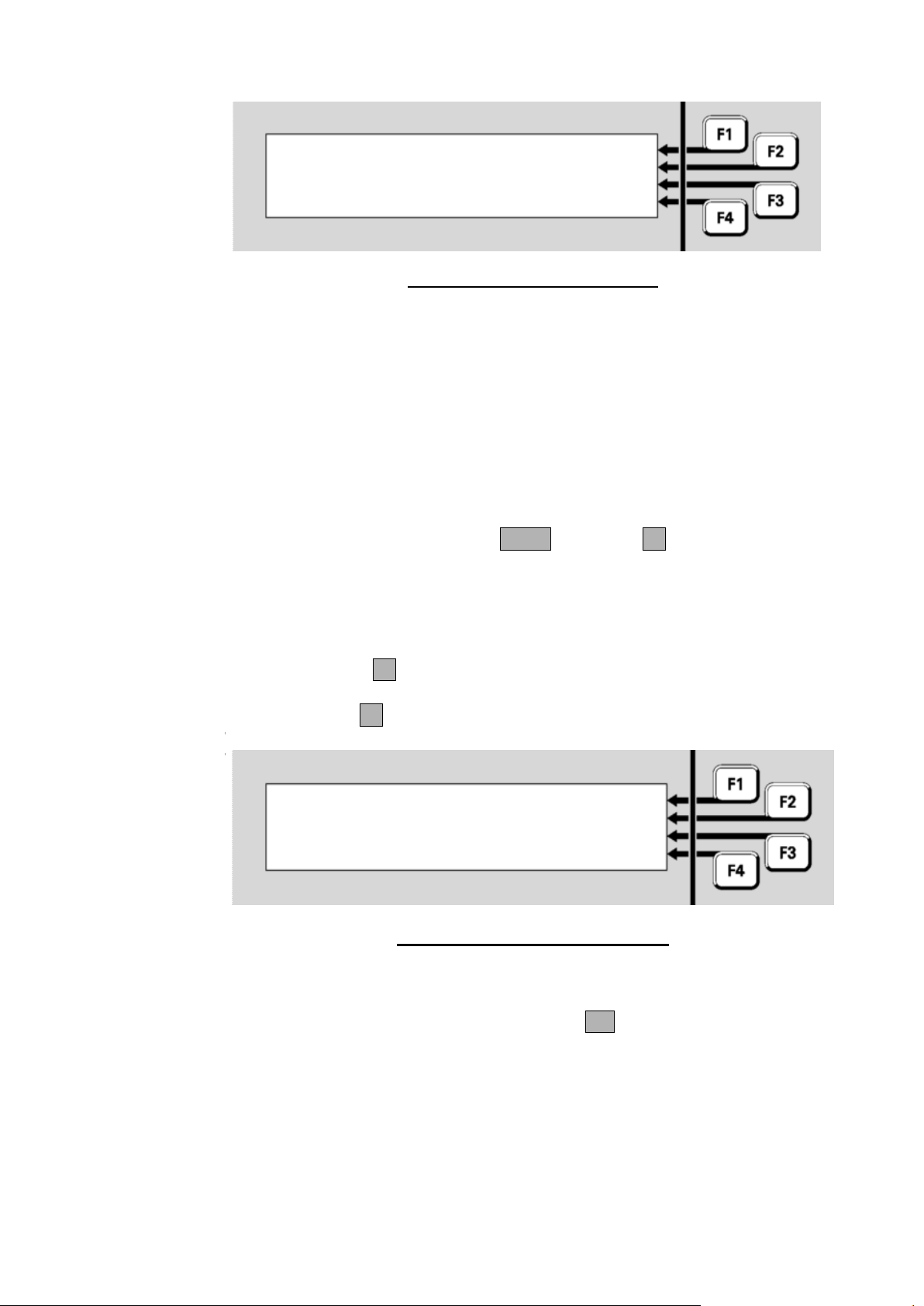
Vigilant MX1 Operator Manual Document: LT0344
Enter point number
:
enter Equip.Device.Subpoint
O
f
f
-
N
o
r
m
a
l
Z
o
n
e
s
P 1 .
135
.
0 814
PH MX Device
|
Shop
|
PREV
Device-fail
|
NEXT
|
MENU
ENTER
Fig 5-5 – Off-Normal Point Display
Line 1 shows the point number, device type and point type.
Line 2 shows the point description.
Line 3 and 4 shows the point status. Refer page 1-12 for details.
In this example, point 1.135.0 is for a device which has been removed or
become disconnected, hence the Device Fail status. ”Shop” is the point
description set in the site-specific configuration. It indicates the physical
location of the device.
From the point display, pressing NEXT or NEXTF3 steps to the next
point.
After the highest numbered point, the list wraps around to the lowest
numbered point again.
Pressing PREVF2 steps to the previous point in the list.
Press ENTERF1 to show the point number entry display:
This allows a new point number to be entered and its status recalled.
Enter the required point number and press OK.
Page 5-4 8 August 2017 Issue 2.4
Fig 5-6 – Point Number Entry Display
Page 55
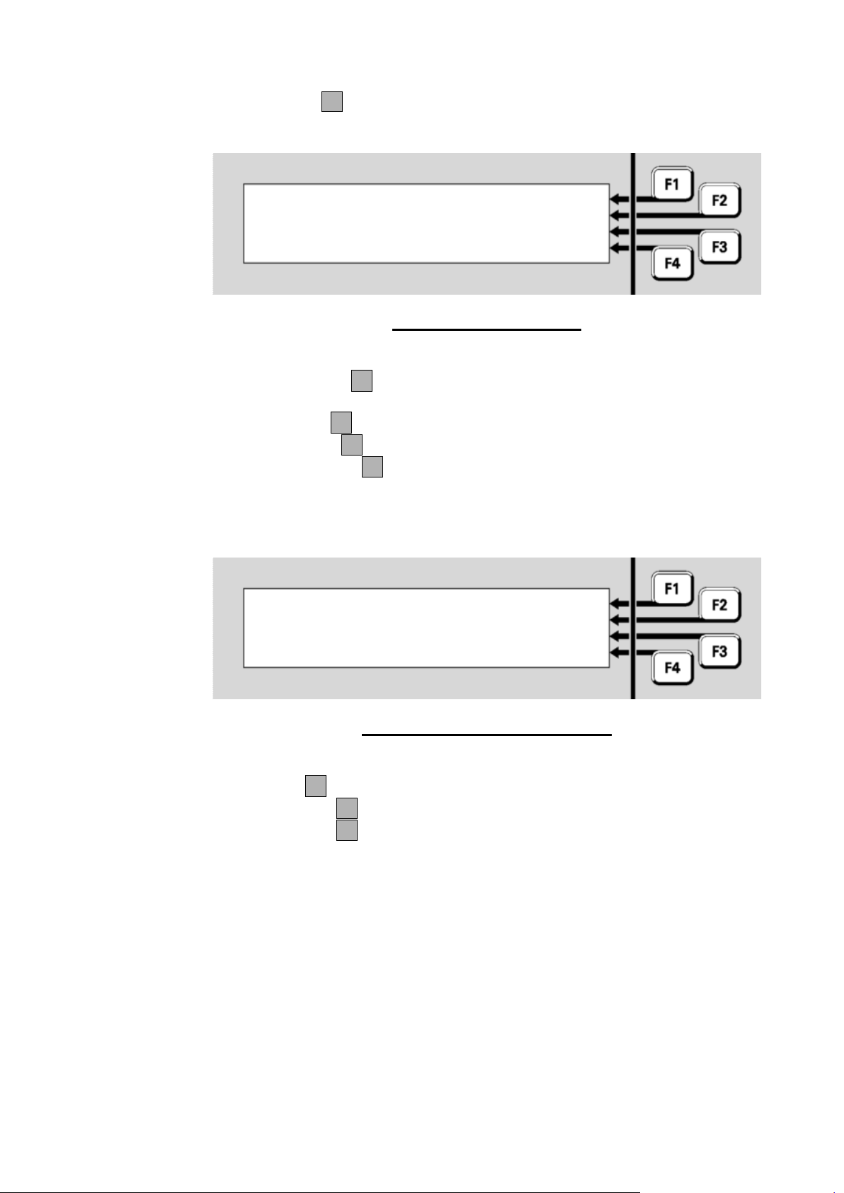
Document: LT0344 Vigilant MX1 Operator Manual
Recall zones : xxxxx
|
LOCAL
|
ALL SIDS
|
ENTR SID
Select SIDs to search |
Recall zones
|
OFF NML
|
ALARMS
|
FAULTS
|
DISABLES
Recall
Zones
The ZONESF2 option in the Recall menu (see Figure 5-2) allows the
off-normal zones to be recalled.
Fig 5-7 – Recall Zones Menu
Press:
OFF NMLF1 to show all off-normal zones (i.e., not in a Normal
state)
ALARMF2 to show all zones in alarm
FAULTSF3 to show all zones in fault
DISABLESF4 to show all disabled zones.
If your panel is connected to a network you will see the following menu
after you select one of the menu items:
Fig 5-8 – Recall Zones Network Menu
Press:
LOCALF1 to show the selected zones on the local MX1
ALL SIDSF2 to show the selected zones on the network
ENTR SIDF3 to show the selected zones on a particular MX1
panel. This will prompt you to enter the SID of the panel to search.
The zones are displayed in numerical order, starting with the lowest
numbered zone. An example is shown in Figure 5.9.
Issue 2.4 8 August 2017 Page 5-5
Page 56
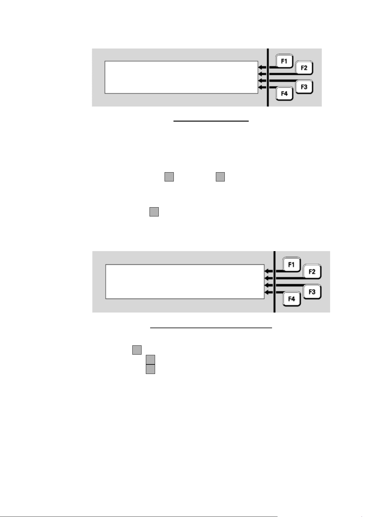
Vigilant MX1 Operator Manual Document: LT0344
Zone 003 Std Detection G1 |
Shop | PREV
| NEXT
Fault | MENU
Recall points : ALL
|
LOCAL
|
ALL SIDS
|
ENTR SID
Select SIDs to search |
All Points
ENTER
Fig 5-9 – Off-Normal Zone
The display shows the zone number and its operating profile on the top
line, the zone text on the second line, and the zone status on the third
and fourth lines. Refer to page 1-15 for details on the zone status
conditions.
Function keys NEXTF3 and PREVF2 step forwards and backwards
through the list of zones.
The ALL-PNTSF3 option in the Recall menu (see Figure 5-2) allows
all configured points to be recalled.
If your panel is connected to a network you will see the following menu:
Fig 5-10 – Recall All Points Network Menu
Press:
LOCALF1 to show the selected points on the local MX1
ALL SIDSF2 to show the selected points on the network
ENTR SIDF3 to show the selected points on a particular MX1
panel. This will prompt you to enter the SID of the panel to search.
All configured points will be displayed starting at the lowest numbered
point, irrespective of the point condition. An example is shown in Figure
5-11.
Page 5-6 8 August 2017 Issue 2.4
Page 57
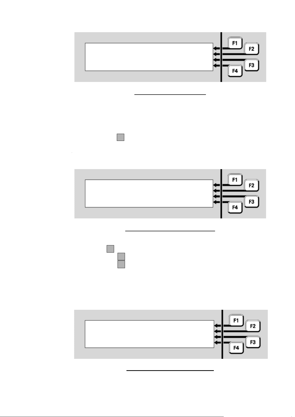
Document: LT0344 Vigilant MX1 Operator Manual
Zone 002 Std Detection G1 | ENTER
Factory | PREV
Normal | NEXT
| MENU
A
l
l
Z
o
n
e
s
Recall zones : ALL
|
LOCAL
|
ALL SIDS
|
ENTR SID
Select SIDs to search |
P 1 . 1 .
0
MIM
800
MX Device
|
ENTER
Office
|
PREV
Normal
|
NEXT
|
MENU
All Zones
Fig 5-11 – Point Recall Display
Point numbering and usage is described in detail in Chapter 1, Point
Numbers (page 1-13).
The ALL ZNSF4 option in the Recall menu (see Figure 5-2) allows all
configured zones to be recalled.
If your panel is connected to a network you will see the following menu:
Press:
LOCALF1 to show the selected zones on the local MX1
ALL SIDSF2 to show the selected zones on the network
ENTR SIDF3 to show the selected zones on a particular MX1
panel. This will prompt you to enter the SID of the panel to search.
All configured zones will be displayed starting at the lowest numbered
zone, irrespective of the zone condition. An example is shown in Figure
5-13.
Issue 2.4 8 August 2017 Page 5-7
Fig 5-12 – Recall Zones Network Menu
Fig 5-13 – Recall Zone Status Display
Page 58
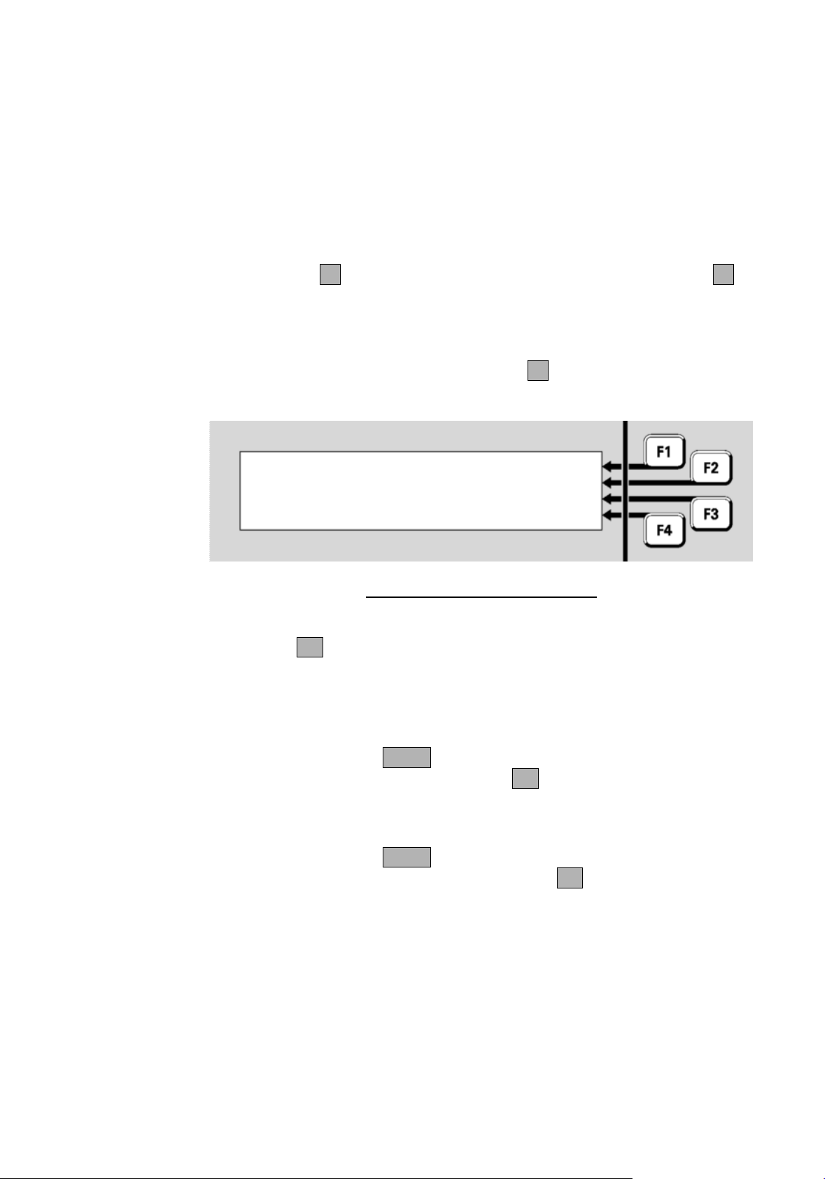
Vigilant MX1 Operator Manual Document: LT0344
Enter zone number
:
Using the Zone Button to Recall Points and Zones
Points
Zones
“002” is the number of the zone. “Std Detection G1” is the name of the
operating profile that has been programmed for the zone.
“Factory” is the description given to the zone to associate it with its
general physical location.
“Normal” indicates that no alarms, faults or other conditions are current
for this zone.
Press NEXTF3 to navigate forward to the next zone, and PREVF2 to
move back to the previous zone.
From the All Zones status display, you can directly enter the number of a
new zone to be displayed. Press ENTERF1 to show the zone number
entry display:
Fig 5-14 – Entering a Zone Number
Enter the number of the zone to be viewed using the numeric keypad,
followed by OK.
To recall a zone, press ZONE from the base display or Alarm List. Enter
the required zone number and press the OK key. This will show the
recall status display for that zone. See chapter 6 for the commands
available on a zone status display.
To recall a point, press ZONE twice from the base display or Alarm List.
Enter the required point number and press the OK key. This will show
the recall status display for that point. See chapter 6 for the commands
available on a point status display.
Page 5-8 8 August 2017 Issue 2.4
Page 59

Document: LT0344 Vigilant MX1 Operator Manual
Topic
See Page
Displaying Zone or Point Command Menu
6-2
Resetting Zones or Points
6-2
Disabling and Enabling Points or Zones
6-6
Testing Zones
6-12
Testing Points
6-16
Viewing Point Values and Settings
6-18
Chapter 6
Zone and Point Functions
Introduction
In this Chapter
This Chapter describes use of the front panel to change the status of
zones and points.
Except where noted, all these commands require operator Access Level
2. See page 1-11 for more information about Access Levels.
Equipment points are described on page 11-2.
Refer to the page number listed in this table for information on a specific
topic.
Issue 2.4 8 August 2017 Page 6-1
Page 60
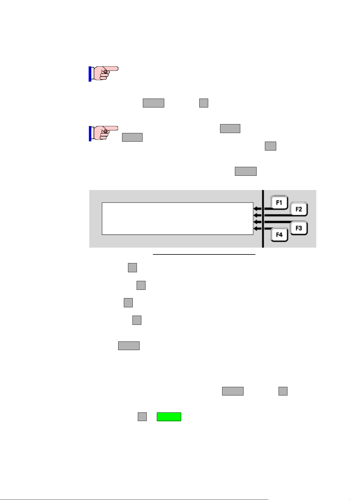
Vigilant MX1 Operator Manual Document: LT0344
This function requires Access Level 2.
Displaying Zone or Point Command Menu
Resetting Zones or Points
Resetting a Zone
P 1 . 1 .
0
MIM
800
MX Device
|
RESET
Office
|
DISABLE
Normal
|
TEST
|
VALUES
From any of the recall point or zone status displays described in Chapter
5, you can press MENU or MENUF4 to see the commands available for
the currently displayed item.
Alternatively, for a zone, press ZONE or for a point press
ZONE twice from the base display or Alarm List. Enter the
required zone or point number and press the OK key. This
will show the recall status display for that zone or point.
For example, in a point recall display pressing MENU will show a menu
of commands.
Fig 6-1 – Recall Point Status Display
RESETF1 will reset the displayed point. See the next section for
more detail.
DISABLEF2 will disable or enable the displayed point. See page 6-
6 for more detail.
TESTF3 will test the point. See pages 6-12 and 6-16 for more
detail.
VALUESF4 will display analogue values for a point. See page 6-18
for more detail. This option is not displayed for a zone.
Pressing MENU again will switch back to the Recall Point or Zone Status
display.
From the recall zone status display, press MENU or MENUF4 to display
the zone menu commands.
Press RESETF1 or RESET to reset the zone.
Page 6-2 8 August 2017 Issue 2.4
Page 61
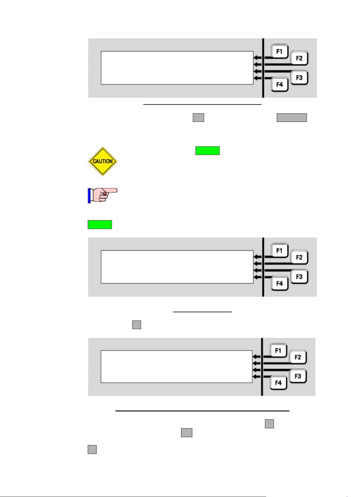
Document: LT0344 Vigilant MX1 Operator Manual
Zone 001 Std Detection G1
Office
Press OK to confirm reset
or CANCEL
Do not press the f.b.p. RESET control when the Alarm List is
being shown unless the intent is to reset the displayed zone
in alarm.
This function requires Access Level 2.
Select an item to reset | ZONE
| POINT
|
|
Reset zone: | -TOEnter nnn for single zone |
or nnn F1 nnn for a range |
F4 to backspace | <-
Resetting a Range of Zones
Fig 6-2 – Zone Reset Confirmation Display
In the confirmation display, press OK to confirm the reset or CANCEL for
no action.
A range of zones can be reset from a base display by pressing the
RESET key. Reset options are as shown below.
Fig 6-3 – Reset Menu
Press ZONEF1.
Fig 6-4 – Zone Number Entry Display – Showing Range Option
Enter the first zone in the range to be reset. Then press F1 and enter the
last zone in the range. Press OK.
F4 can be used as a backspace key.
Issue 2.4 8 August 2017 Page 6-3
Page 62
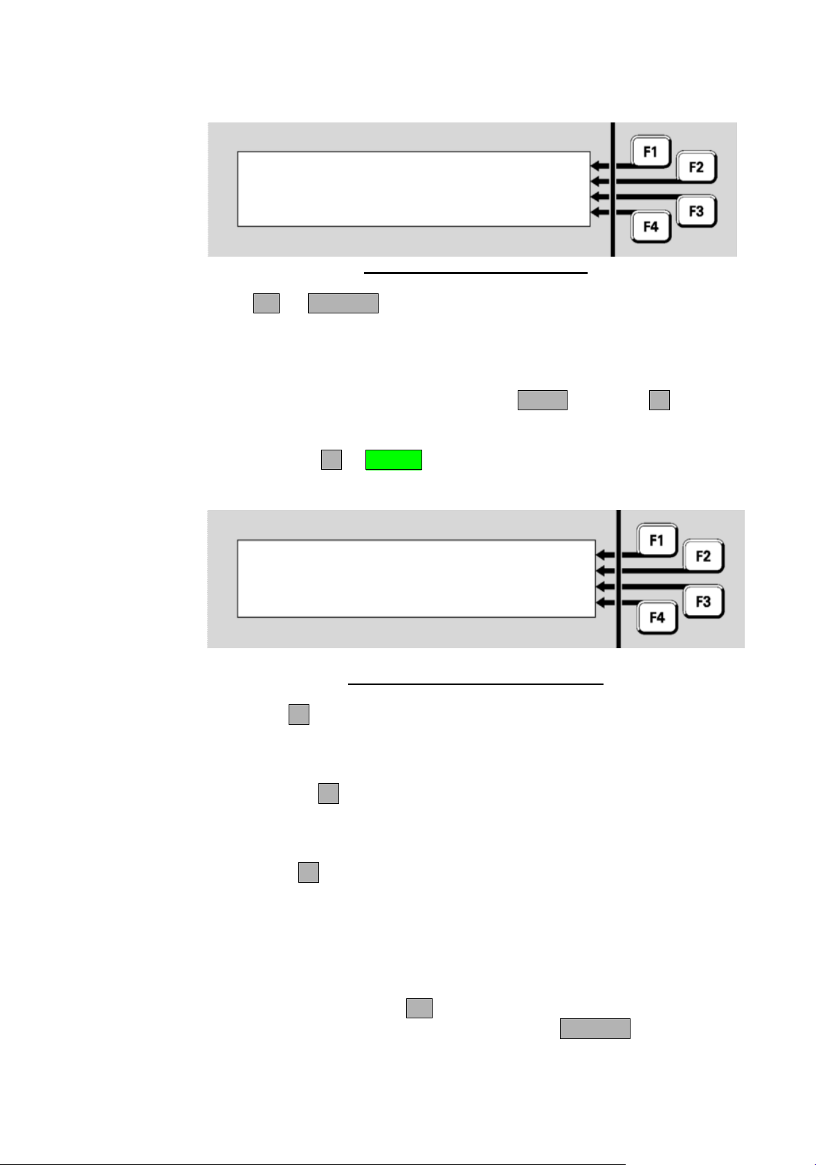
Vigilant MX1 Operator Manual Document: LT0344
Reset point | FULL
P1.1.0 MIM800 MX Device | HISTORY
| TRACK
Select reset option or CANCEL |
Resetting a Point
Zones 1-to-3
Press OK to full reset
or CANCEL
The resulting menu offers one or more reset options and a cancel option.
Press OK, or CANCEL. The system will perform the reset on the
configured zones in the range and then display the recall zone status
display for the first zone so that the result of the command can be
viewed.
From the recall point status display, press MENU or MENUF4 to display
the point commands.
Press RESETF1 or RESET to reset the point. There are several
options for resetting a point:
FULLF1 is the basic reset to restore a point to a Normal state. The
alarm and fault states are cleared (if possible) and any tests in
progress are cancelled. This option would normally be used only for
latching devices.
HISTORYF2 sets the point’s History High and History Low values to
the current value, if it has history values. If it does not, this has no
effect. Generally, only analogue addressable detectors have history
values.
TRACKF3 resets the point’s Tracked value to the current value, if it
has one. If it does not, this has no effect. Generally, only analogue
addressable detectors have Tracked values. This option is useful for
resetting the tracking after a new or cleaned detector has been
installed.
After selecting the type of reset required you will be asked to confirm or
cancel the reset. Pressing OK will confirm the reset and display the
recall display for the point concerned. Pressing CANCEL will return to
the display shown above.
Page 6-4 8 August 2017 Issue 2.4
Fig 6-5 – Zone Reset Option Menu
Fig 6-6 – Options For Resetting a Point
Page 63
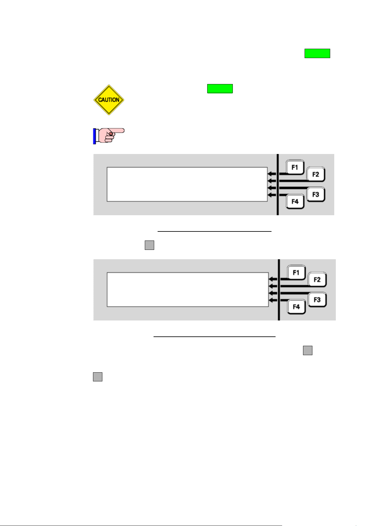
Document: LT0344 Vigilant MX1 Operator Manual
Do not press the f.b.p. RESET key when the Alarm List is
being shown unless the intent is to reset the displayed zone
in alarm.
This function requires Access Level 2.
Select an item to reset | ZONE
| POINT
|
|
Reset point | -TO: |
Enter E.D.S for single point |
or E.D.S F1 E.D.S for range | <-
Resetting a Range of Points
A range of points can be reset from a base display by using the RESET
key. Reset options are as shown below.
Fig 6-7 – Selecting an Item to be Reset
Press POINTF2.
Fig 6-8 – Enter a Point Range to be Reset
Enter the first point in the range that is to be reset. Then press F1 and
enter the last point in the range.
F4 can be used as a backspace key to correct wrong entries.
For devices on the local panel, you may enter
a single device or a range of devices, or
a single point, or a range of points within the same device
For devices on a remote panel, you may enter
a single point, or a range of points within the same device
For information on point numbers and ranges refer to “Point Numbers”
(page 1-13). The MX1 automatically enters the end-point in the range at
the same level as the start point already entered by the operator. For
Issue 2.4 8 August 2017 Page 6-5
example, if the first point in the range is entered as “1.1.1” and –TO-
Page 64

Vigilant MX1 Operator Manual Document: LT0344
Reset point range | FULL
P1.1.1-1.1.3 | HISTORY
| TRACK
Select reset option or CANCEL |
Disabling and Enabling Points or Zones
Description of Operation
F1 is then pressed, the prompt “1.1._” will appear.
Once the point number(s) are entered, press OK and you will then be
asked to select the reset option. Refer to “Resetting a Point” (page 6-4)
for details of the point reset options.
Fig 6-9 – Selecting The Reset Option
Press FULLF1, HISTORYF2 or TRACKF3. You will then be asked
for confirmation. Press OK.
The configured points in the range will be reset for the selected option.
The display will then show the recall point status display for the first point
in the selected range. Use the menu options to navigate through the
point range, or press CANCEL to return to the base display.
If no points are configured in the selected range, the message “No Valid
Points Selected” will be shown briefly.
In general, each zone, each device, and each point may be disabled to
stop conditions on the item affecting the system. For example, the
smoke sensor point of an 814PH detector may be disabled to stop alarm
monitoring for smoke while certain building work is going on around the
detector. This will leave the heat sensor point still operational and able to
detect alarms.
Disabling a device by entering the equipment and device number (i.e., no
subpoint) will normally disable all sensor or input subpoints. With these
subpoints disabled, a detector may be completely removed from the loop
with the consequential fault condition(s) masked by disable.
Where it is required to disable only a particular element of the sensor,
e.g., heat or smoke, then the relevant subpoint only should be disabled.
Note that although device fail conditions are signalled from subpoint 0,
fault conditions will still be signalled from other sensor input subpoints if a
device is removed with only subpoint 0 disabled.
Page 6-6 8 August 2017 Issue 2.4
Page 65

Document: LT0344 Vigilant MX1 Operator Manual
Some subpoints will be programmed such that they cannot
ordinarily be disabled, e.g., detector LED subpoints.
However, if these subpoints are in a Device Fail condition,
they can be forced into a disable state by first logging into
Access Level 3 before using the disable point command(s).
In this case the confirmation screen will describe the
disablement as a “Force Disable”.
As soon as a zone is enabled it will resume its programmed
behaviour in activating alarm devices, alarm outputs and
fault outputs.
MX1 uses non-volatile memory to store disable status for
zones, points, ancillary groups and the alarm devices. If the
MX1 is powered down or restarted within 10 seconds of
disabling or enabling a zone, point, etc., then the new status
may not be stored correctly and the old status will remain.
Do not press the f.b.p. DISABLE control when the Alarm List
is being shown unless the intent is to disable the displayed
zone in alarm.
This function requires Access Level 2.
Disabling or enabling a Point from a Recall Point Status display
Disabling or Enabling a range of Points
If a zone is disabled this will disable functionality for all its points as well,
unless the points map to another zone or their status is used directly. In
this case it will be necessary to disable the points directly.
If all points that map to a zone are disabled then the zone becomes
disabled automatically. It will not be possible to enable the zone until at
least one point that maps to the zone is enabled. Note that you must
separately enable the zone after you have enabled the point.
From a recall point status display (refer Chapter 5), press PREVF2 or
NEXTF3 to reach the required point, then press MENUF4.
Press DISABLEF2 or DISABLE to disable or enable the point. In the
confirmation display, press OK to confirm or CANCEL for no action.
If this point is configured so that it cannot be disabled, a message
“This point cannot be disabled” will be displayed briefly.
From the base display, press DISABLE, then POINT F2.
Issue 2.4 8 August 2017 Page 6-7
Page 66
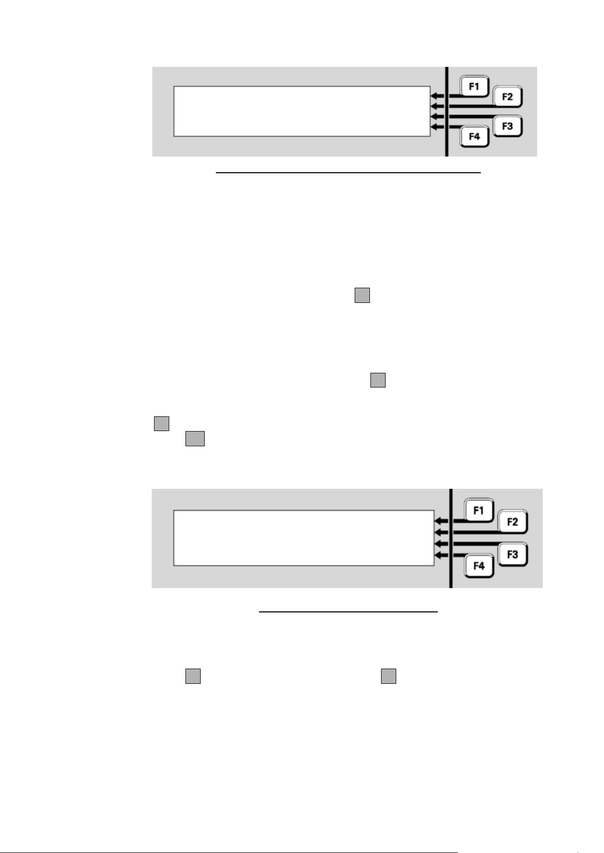
Vigilant MX1 Operator Manual Document: LT0344
Disable Point | -TO: |
Enter E.D.S for single point |
or E.D.S F1 E.D.S for range | <-
P1.1.2-1.1.3 | DISABLE
2 disabled |
0 enabled |
Select command or CANCEL | ENABLE
Fig 6-10 – Point Number Entry Display – Disable Points
For devices on the local panel, you may enter
a single device or a range of devices, or
a single point, or a range of points within the same device
For devices on a remote panel, you may enter
a single point, or a range of points within the same device
Enter the first point in the range, then F1 followed by the last point in the
range. Point numbering is described in “Point Numbers” on page 1-13.
Note that the selected range cannot span equipment numbers. If the
starting point is a device number then the end point must be another
device on the same equipment number. If the starting point number
includes a sub-point, then the end point must include a sub-point of the
same device. After pressing the -to-F1 key, the end point entry is
automatically configured to the allowed range.
F4 can be used to backspace to correct wrong entries.
Press OK. If no configured points exist in the entered range, “No Valid
Points Selected” is shown briefly before the point number entry display
(Fig 6-10) is re-displayed.
Fig 6-11 – Point Disable/Enable Menu
Fig 6-11 shows the number of configured points in the range that are
already disabled and enabled.
Press F1 to disable the range of points, or F4 to enable the range of
points. A confirmation display will be shown.
Page 6-8 8 August 2017 Issue 2.4
Page 67
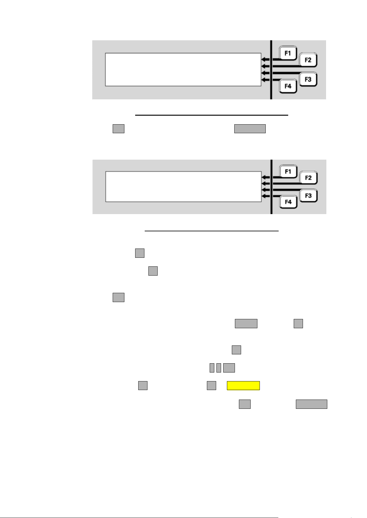
Document: LT0344 Vigilant MX1 Operator Manual
P1.1.2-1.1.3
Disable all points in range
Press OK to confirm
or CANCEL
P1.1.2-1.1.3 | ALL
|
F1 enables all in range |
F4 enables normal in range | NORMAL
Disabling or Enabling a Zone from Recall Display
Fig 6-12 – Disable Point Range Confirmation Display
Press OK to carry out the function or press CANCEL to abort the
command and return to the previous display.
On Enabling a range of points the following choice is given:
Fig 6-13 – Enable Point Range Choice Display
Pressing:
- ALLF1 will enable all points in the range irrespective of their
status (e.g., points could be in alarm).
- NORMALF4 will enable only those points in the range that are in
the Normal condition (i.e., points in alarm, fault, test, etc., will
remain disabled).
Press OK in the following confirmation screen to carry out the selected
point enables.
From the Recall Zone Status display, press MENU or MENUF4 to
display the zone commands.
To jump to a specific zone, press ENTERF1 from the Recall Zone
Status display and enter the required zone number - for example,
Zone 23. This would be entered as 2 3 OK.
Press MENUF4, then DISABLEF2 or DISABLE to disable the zone.
If the zone is already disabled, the F2 option will be ENABLE instead of
DISABLE. In the confirmation display, press OK to confirm or CANCEL
to abort the command.
Issue 2.4 8 August 2017 Page 6-9
Page 68
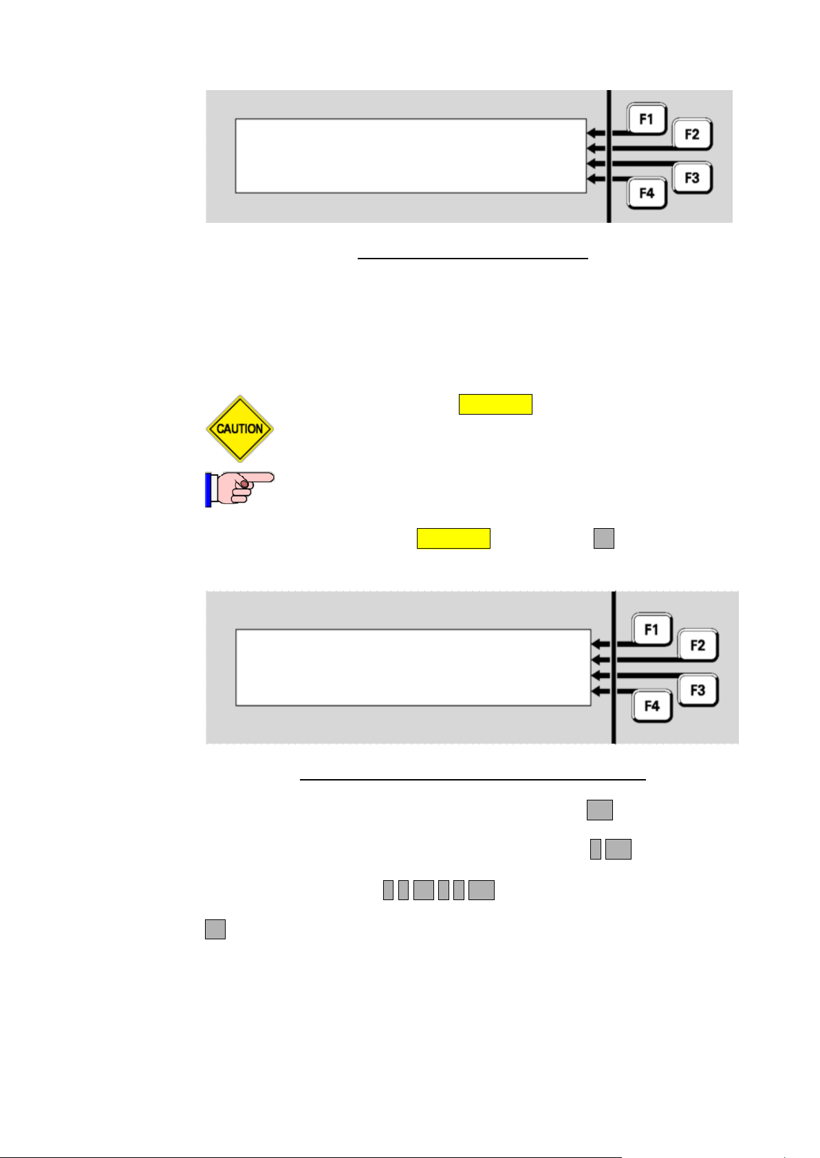
Vigilant MX1 Operator Manual Document: LT0344
Zone 001 Std Detection G1
Office
Press OK to confirm Disable
or CANCEL for no action
Do not press the f.b.p. DISABLE control when the Alarm List
is being shown unless the intent is to disable the displayed
zone in alarm.
This function requires Access Level 2.
Disable zone: | -to-
Enter nnn for single zone |
or nnn F1 nnn for a range |
F4 to backspace | <-
Disabling or Enabling a Zone or a Zone Range
Fig 6-14 – Confirming Zone Disable
When a zone is disabled, the corresponding zone indicator will light
yellow.
If this zone is configured so that it cannot be disabled, a message,
“This zone cannot be disabled”, will be displayed briefly.
From the base display press DISABLE, then ZONEF1. A single zone
or a range of zone numbers can be entered in this display:
Fig 6-15 – Entering Zones To Be Disabled or Enabled
Enter a single zone or the required range and press OK. For example:
If only zone 2 is to be disabled, this is entered as 2 OK.
If the zone range 23 to 38 inclusive is to be enabled or disabled, this
would be entered as 2 3 F1 3 8 OK.
F4 can be used as a backspace key to correct entry mistakes.
If a single zone has been entered, this display results;
Page 6-10 8 August 2017 Issue 2.4
Page 69
Document: LT0344 Vigilant MX1 Operator Manual
Zone 001 Std Detection G1 | DISABLE
Office |
Select operation on zone |
or CANCEL | ENABLE
Zones 1 to 3 | DISABLE
0 zones disabled |
3 zones enabled |
Select command or CANCEL | ENABLE
Zones 1 to 3
Press OK to Disable All zones in range
or CANCEL
0 Alarms
Fig 6-16 – Disabling Or Enabling a Single Zone
Press DISABLE-F1 to disable the zone or ENABLE-F4 to enable the
zone. Press OK in the following confirmation display to complete the
command, or CANCEL to abort it.
If a range of zones has been entered, the next display shows how many
configured disabled and enabled zones there are in this range. Note that
the entered zone range may include zone numbers that are not
configured for this system, and therefore the sum of the disabled and
enabled zones displayed may not tally with the apparent number of
zones.
Fig 6-17 – Displaying/Enabling a Range of Zones
To disable the range of zones, press DISABLEF1, and a confirmation
display will result.
Fig 6-18 – Disabling All Zones an a Range
Press OK to confirm the command. You will be returned to the Recall
Zone Status display for the first zone in the specified range. Press
CANCEL to return to the previous display.
To enable the zones in the range (refer Fig 6-17), press ENABLEF4.
Issue 2.4 8 August 2017 Page 6-11
Page 70
Vigilant MX1 Operator Manual Document: LT0344
Zones 1 to 3 | ALL
F1 enables all in range |
F4 enables normal in range |
| NORMAL
If any of these zones are in Alarm or Fault states, they will
resume their programmed behaviour in activating alarm
devices and fault outputs once they have been enabled.
Attempting to enable a zone that has all of its points
disabled will not work even though it falls within the
specified range of zones. To enable the zone, one or
more of its points will need to be enabled first.
This function requires Access Level 2.
Zone 001 Std Detection G1 |ALRM TST
Office | OPERATE
Normal |AUTO RST
| FLT TST
Testing Zones
Fig 6-19 – Choice for Enabling a Range Of Zones
Selecting ALLF1 will enable all zones in the range, irrespective of their
status.
If NORMALF4 is selected, only those zones in the range that are in the
normal state will be enabled. Since (dependant on the configuration in
use) enabling zones in alarm could activate remote signalling, alarm
devices, etc., this option permits the system to be returned to service
without accidentally enabling an alarm and perhaps signalling the
brigade.
In the confirmation display press OK to enable the zones in the range, or
CANCEL to abort the command.
From the recall zone status display, press MENU or MENUF4 to display
the menu options, then press TESTF3 to display the zone test menu.
Alternatively, from the base display press TESTS, INITIATEF4,
ZONEF1 and enter the zone number.
Page 6-12 8 August 2017 Issue 2.4
Fig 6-20 – Zone Test Status and Menu
Page 71

Document: LT0344 Vigilant MX1 Operator Manual
Do not start any zone tests while the zone is being reset
(resetting is shown on the status screen) as the reset
process will clear the test.
Zone 001 Std Detection G1 |
Office | ENABLE
Alarm | RESET
Disabled AlarmTst |
Alarm Test
Test options for a zone are:
ALRM TSTF1 – perform an alarm test on this zone.
OPERATEF2 – force all output points controlled by this zone to
operate.
AUTO RSTF3 – put this zone into Auto-Reset test.
FLT TSTF4 – perform a fault test on the zone.
If any of these test options is selected, a confirmation display/prompt will
be displayed. Press OK to confirm that the test should start.
While the test is running, none of the other tests can be started for this
zone. However, tests can be started or stopped on other zones, and
other front panel functions can be used, for example viewing history,
point status recalls, etc.
The zone test can be stopped by resetting the zone. This is most easily
done by pressing the TESTS key then SEARCHF1, to display the list of
items currently being tested, stepping to the desired zone under test by
pressing NEXT, and pressing RESET then OK to confirm the reset.
This test generates an alarm in the zone by finding all enabled points that
are mapped to the zone and putting them into a test alarm condition.
Those devices with a physical alarm test capability will have it activated.
Other devices will have an alarm condition simulated by the MX1. An
Alarm Test can be performed on both Enabled and Disabled Zones. The
Enabled zones will be automatically disabled at the start of the test so as
not to activate any outputs.
The zone can be manually enabled during the test so that the flow-on
effects of the alarm can be observed.
Fig 6-21 – Zone Alarm Test Status and Menu
Press ENABLE F2 to enable the zone. Note that enabling the zone
Issue 2.4 8 August 2017 Page 6-13
while the alarm test is in progress may sound the alarm devices, call the
Page 72
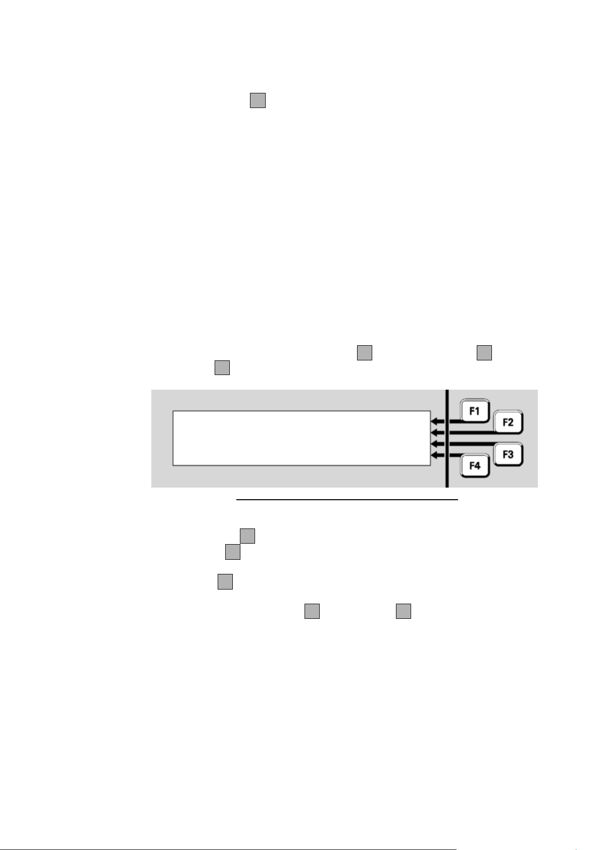
Vigilant MX1 Operator Manual Document: LT0344
Zone 001 Std Detection G1 |STOP TST
Office | ENABLE
| RESET
Disabled TestOp |
Operate Test
Auto-Reset
brigade, etc., when the zone goes into alarm.
Pressing RESETF3 will end the test and clear any alarm indications. It
will also restore the zone’s enable/disable status to what it was before
the test was started.
The test passes when the zone goes into the alarm condition. The zone
will go into alarm condition only when all enabled points mapped to it
have gone into alarm. If this does not occur (e.g., because a device is in
Device Fail or all alarm-generating points are disabled) within three
minutes the test will fail.
Note: Each point put into alarm by the Zone alarm test will be logged (if
enabled) to the printer and history, show Alarm in their status and
activate any directly controlled outputs.
This test will allow all the output points controlled by the zone to be
operated. After the test command is confirmed, the zone will be
disabled. It is necessary to enable the zone to actually operate all the
output points. They will then operate for a programmed time (typically 5
seconds) or until the zone is disabled (F2), the test stopped (F1), or the
zone reset (F3).
Fig 6-22 – Zone Operate Test Status and Menu
During the test, the menu options are:
STOP TSTF1 – stops the operate test on this zone.
ENABLEF2 – will enable the zone in order to allow the output points
to be actually operated.
RESETF3 – stops the operate test and also resets any latched
states (e.g., faults) for this zone.
Note that both STOP TST F1 and RESETF3 will also restore the
zone’s enable/disable status to what it was before the test was started.
The Auto-Reset test allows in-situ alarm testing of detectors and devices
mapped to the selected zone without the need for a second person
resetting alarms at the MX1 panel.
The test bypasses all filtering, i.e., AVF, SmartSense and FastLogic are
turned off, so that each device goes into alarm as fast as possible.
The Auto-Reset test uses the alarm devices to signal to the tester when a
device mapped to the tested zone has gone into alarm (or Active Input).
Page 6-14 8 August 2017 Issue 2.4
The alarm devices are operated for approximately 3 to 4 seconds, but
Page 73
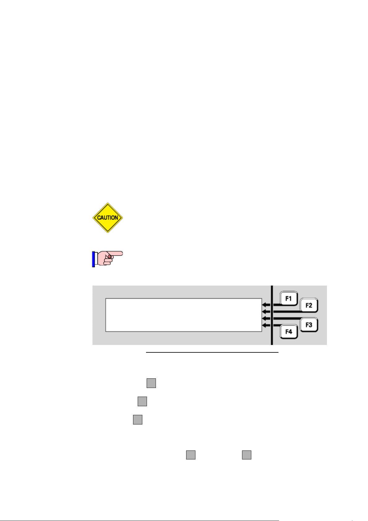
Document: LT0344 Vigilant MX1 Operator Manual
If the zone is manually enabled during the Auto-Reset test all
outputs controlled by the zone (including, for example, alarm
routing) will operate.
If the zone is configured so that it cannot be disabled,
Auto-Reset test cannot be used.
Zone 001 Std Detection G1 |STOP TST
Office | ENABLE
| RESET
Disabled AutoReset |
only if the alarm devices are enabled. As additional points are tested, the
alarm devices will operate as noted.
Once the point has gone into alarm (or into Active Input) and been
processed by the zone the point is then ignored until it returns to normal
(for at least 60 seconds). This allows devices to be tested quickly in
succession, without waiting for smoke to clear or temperature to drop, for
example. The zone status display and alarm LED continue indicating
alarm even though the point alarms clears.
The Alarm (or Active Input) event for each point will be recorded in the
event history, if event logging has been configured for the point. See
Chapter 4 for more about viewing the event history.
The zone is automatically disabled during Auto-Reset test to prevent
operation of mapped outputs, the alarm devices and alarm routing.
However outputs activated directly from the point states will continue to
work during Auto-Reset test unless the points or outputs are disabled.
Fig 6-23 – Zone Auto-Reset Test Status Menu
During the test, the menu options are:
STOP TSTF1 – stops the Auto-Reset test on this zone and then
enables the zone.
ENABLEF2 – will enable the zone in order to allow the mapped
output points to be operated.
RESETF3 – stops the Auto-Reset test and also resets any latched
indications (e.g. fault) for this zone. The zone will revert to its original
Disabled state (unless this was changed during the test).
Note that both STOP TST F1 and RESETF3 will also restore the
zone’s enable/disable status to what it was before the test was started.
Issue 2.4 8 August 2017 Page 6-15
Page 74
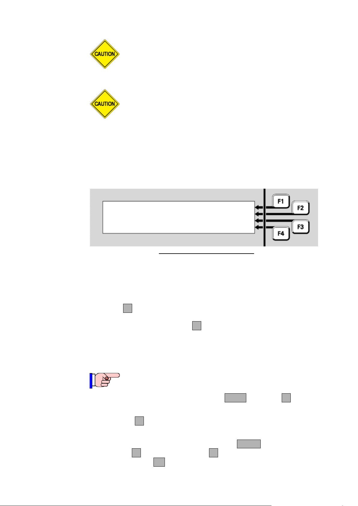
Vigilant MX1 Operator Manual Document: LT0344
The Auto-Reset test will automatically cancel if no new
alarm is received for two hours. In this case, the zone will
revert to the state it was in (enabled or disabled) when the
test was started.
On exiting the test (whether stopped, reset, or timeout) if
an alarm is still present (e.g., call point left operated) the
alarm will be treated normally and may generate a
nuisance alarm. Therefore it is recommended the zone
be disabled before the test, and enabled again only after
confirming 1-2 minutes after the test is exited that the
state of the zone is normal.
Zone 001 Std Detection G1 |
Office | ENABLE
| RESET
Fault Disabled FltTest |
This function requires Access Level 2.
Fault Test
Testing Points
This test generates a fault condition for the zone. You will be asked to
confirm or cancel the test. The following display will be shown during the
test.
Fig 6-24 – Fault Test Status Menu
If the zone does not go into fault, the test fails.
Note that the test will disable the zone being tested, and the fault is
simulated. If it is required to test how the system is affected by the zone
fault, the zone can be manually enabled during the test by pressing
ENABLEF2.
To stop the test, press RESETF3. This will also restore the zone’s
enable/disable status to what it was before the test was started.
From the recall point status display, press MENU or MENUF4 to display
the menu options.
Press TESTF3 to display the test options for the point, which will
depend on the point type, as described in the following sections.
Alternatively, from the base display, press the TESTS key,
Page 6-16 8 August 2017 Issue 2.4
INITIATEF4 and select POINTF2. Enter the required point
number, then press OK.
Page 75
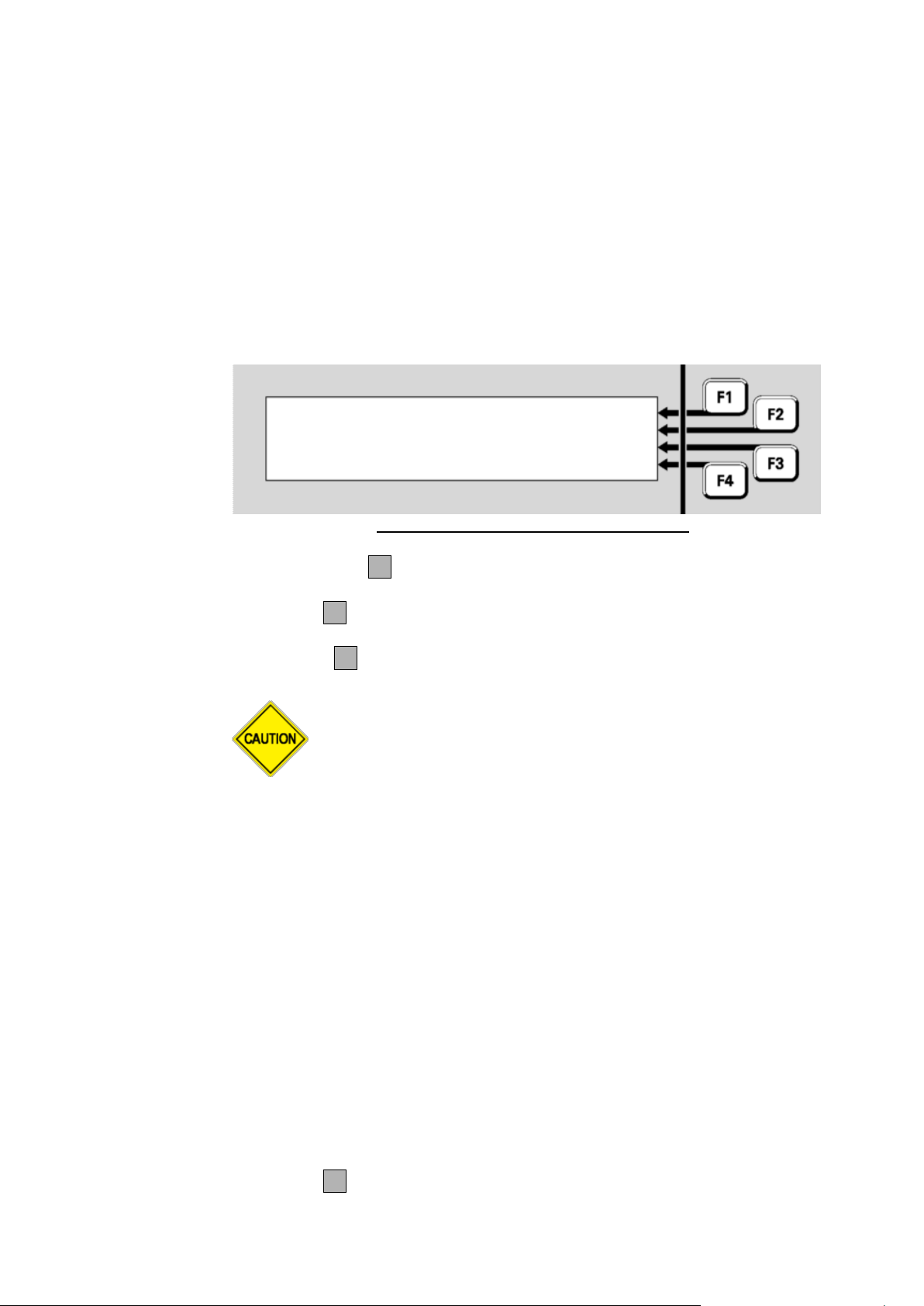
Document: LT0344 Vigilant MX1 Operator Manual
WARNING: the Alarm and Fast point tests do not
automatically disable the point (or mapped zones) so all
programmed alarm devices and alarm routing operate as for
a real alarm.
Disabling the point or mapped zone(s) before the test will
prevent these operating, and only the display and zone
indicator will show the alarm.
Addressable Detectors and Modules
Analogue
Input Point
Input Points
Output Points
P 1 .
32 . 1 814
CH CO
|
ALRM TST
Shop
|
FAST
Normal
|
RESET
|
Addressable devices, such as detectors, have several inputs and outputs
differentiated by the sub-point number. For example, an MX 814CH
detector has:
An analogue input point for the CO sensor,
An analogue input point for the heat sensor,
An output point for the integral LED,
An output point for the remote indicator,
An output point for a functional base.
Each point can be tested independently.
The test options for an analogue input point are:
Fig 6-25 – Analogue Input Point Test Menu
ALRM TSTF1 starts a full alarm test. Any programmed delays and
algorithms for the point will be included.
FASTF2 starts a fast alarm test, bypassing any programmed delays
and algorithms.
RESETF3 resets the point.
The amount of time taken for an Alarm or Fast test is dependent on the
type of device being tested, and on detailed settings in the system
configuration. For example, heat and smoke detectors with nuisance
alarm rejection algorithms will react more slowly to an Alarm test than to
a Fast test, whereas a contact input point will react quickly to both Alarm
and Fast tests.
An input point is something such as General Purpose Input 1 on the
controller board. There are no test options for these points.
An output point is something that can be controlled, such as an MX
device LED or an ancillary relay.
Issue 2.4 8 August 2017 Page 6-17
Test options for output points are:
OPONF1 puts the point into the Operated state, after a confirmation
prompt.
Page 76
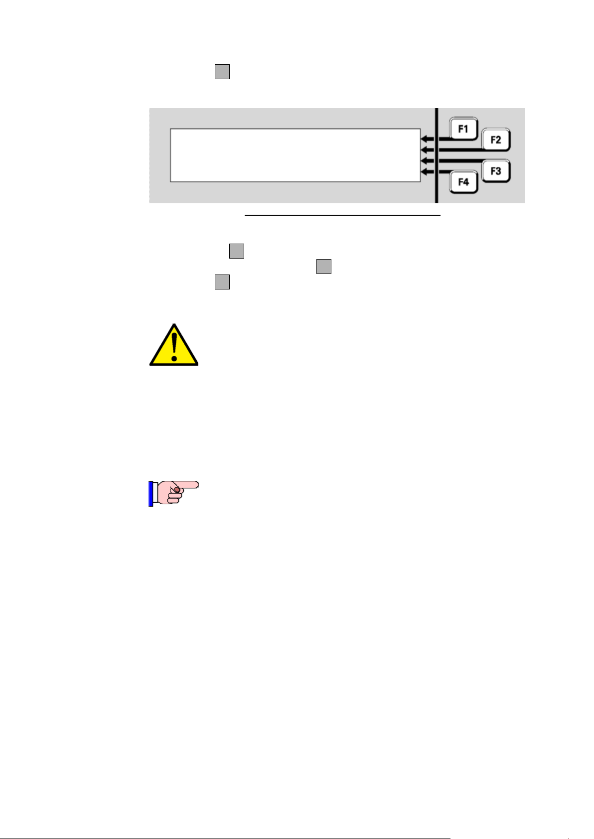
Vigilant MX1 Operator Manual Document: LT0344
P241.8.0 |
Ancillary Relay 1 | DISABLE
| RESET
TestOp |
The point is not automatically disabled by this test, so
testing some outputs may activate external equipment such
as sounders, door releases or even fire suppression
equipment.
Also, at most 10 detector LEDs can be turned on at the
same time. Testing more than 10 simultaneously will still
pass, just the LED will not turn on.
This function requires Access Level 2.
Viewing Point Values and Settings
Using Point Value Data
RESETF3 resets the point, including any latched states and turns
off any TestOp state.
Fig 6-26 – Output Point - Test in Progress
While the Operate Test is active, the test options are:
DISABLEF2 will disable the point. If the point is already disabled
this option will be ENABLEF2.
RESETF3 resets the point (stopping the test), including any latched
states.
MX1 translates sensor readings into analogue values. These values are
processed by algorithms to determine the status of the point. The raw
values, equivalent levels measured in physical units (for example, ppm
CO, oC Temperature, % Obscuration, % Alarm) and algorithms for a
point can be recalled on the display.
These are intended for device fault or performance diagnosis, and are
not very meaningful without a good understanding of the system.
Page 6-18 8 August 2017 Issue 2.4
Page 77
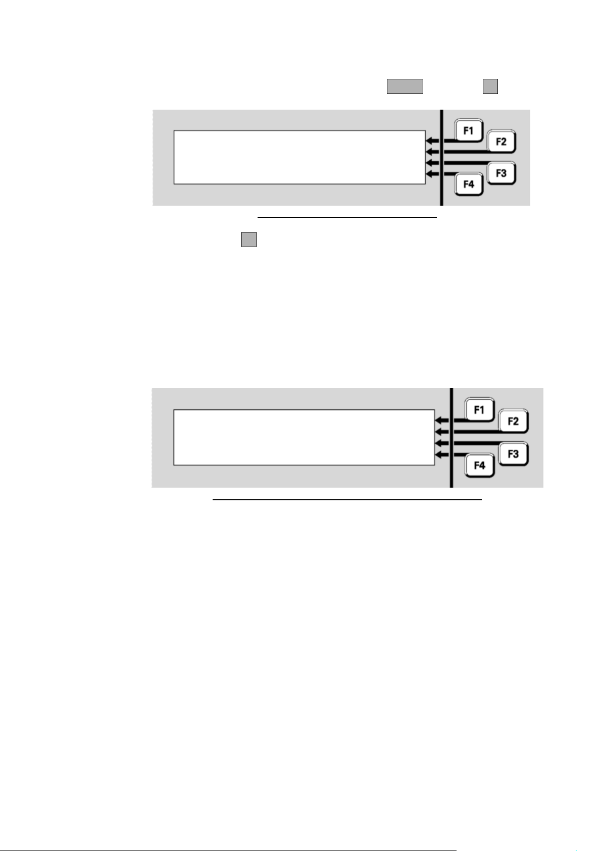
Document: LT0344 Vigilant MX1 Operator Manual
Displaying Point Values
Current Level Values
P 1 .
32 . 1 814
CH CO
|
RAW
Shop
|
PREV
CL
:
0
ppm AS
:
38
(
32 ) |
NEXT
|
DAY OPRN
P 1 .
32 . 1 814
CH CO
|
RESET
Shop
|
DISABLE
Normal
|
TEST
|
VALUES
From the Recall Point Status display, press MENU or MENUF4:
Fig 6-27 – Recall Point Status Display
Press VALUESF4 to view the point’s current levels. Note that not all
points have information for any or all of these displays. For those points,
the MX1 displays messages to that effect.
These examples show typical displays for the points of an MX 814CH
combined carbon monoxide and heat addressable detector.
The display shows the sensor/input current level, that is, a value
converted from the raw value into appropriate, real-world units, together
with the pre-alarm and alarm thresholds.
Fig 6-28 – Point Current-Level Display – Physical Values
CL - Current level in appropriate units for the device type, in this case,
parts per million of carbon monoxide.
AS - Alarm Sensitivity (threshold) in parts per million of carbon
monoxide, followed by the Pre-Alarm Sensitivity (threshold) in parts
per million of carbon monoxide in brackets for the current algorithm
(day or night mode). For smoke detectors using the fast logic
algorithm the alarm sensitivity is shown as 0.0 = Low, 0.1 = Med, 0.2
= High; and the pre-alarm sensitivity is always 0.
For heat devices, the fourth line may also contain Rate-of-Rise (ROR)
information.
The displayed values will be updated at about 5 second intervals, as new
readings are received from the detector.
Issue 2.4 8 August 2017 Page 6-19
Page 78

Vigilant MX1 Operator Manual Document: LT0344
Raw (Unconverted) Data Readings
P 1 .
32 . 1 814
CH CO
|
CUR
Shop
|
PREV
CV : 28
TV : 25
|
NEXT
HH : 30
HL : 25
|
DAY OPRN
Pressing RAWF1 will show the raw (unconverted) readings from the
sensor/input:
Fig 6-29 – Point Raw-Value Display
The readings displayed will depend on the MX point type and include:
CV - Current Value, or RAW - raw value. The unconverted current
value or reading for the sensor or input, but calibrated as required for
the device.
If the raw value from the sensor indicates a fault (e.g., very low value)
then the raw value is the uncalibrated value so the actual fault can be
seen. Also the current level will be 0.
TV - Tracked Value, a long-term smoothed version of CV. For 801F
and 801FEx flame detectors this shows the fault status.
HH and HL - History High and History Low are the highest and lowest
values of CV since the point’s history was last reset (see page 6-4).
For heat sensors that have Rate-of-Rise enabled the current rate-of-
rise (RoR) and the highest rate-of-rise (RoRHH) values are also
shown.
For photoelectric sensors, the contamination level is shown on the
third line.
H% shows the history high as a percentage of the alarm threshold.
For example, H% = 120 means the input went to 120% of the alarm
threshold.
To return to the Point Current-Level Display (physical units of measure)
press CURF1.
Page 6-20 8 August 2017 Issue 2.4
Page 79

Document: LT0344 Vigilant MX1 Operator Manual
Algorithm
Dirty
P 1 .
32 . 1 814
CH CO
|
CUR
Shop
|
PREV
38
ppm
|
NEXT
|
NGT OPRN
Pressing the DAY OPRNF4 key on any point value display will show
the Day algorithm for that point if the point is on an MX1 panel.
Fig 6-30 – Point Algorithm Settings
On the third line the name of the Day algorithm will be shown – typically
this will describe the detection mode and sensitivity. Then pressing NGT
OPRNF4 will show the name of the Night algorithm (usually this will be
the same as the Day algorithm). The currently used sensitivity settings
are shown in the Point Current Level Display (Fig 6.28).
Pressing the DIRTYF4 key on any point value display will show the
percent dirty values for that point if the point is on an MX4428 panel.
Issue 2.4 8 August 2017 Page 6-21
Page 80

Page 81
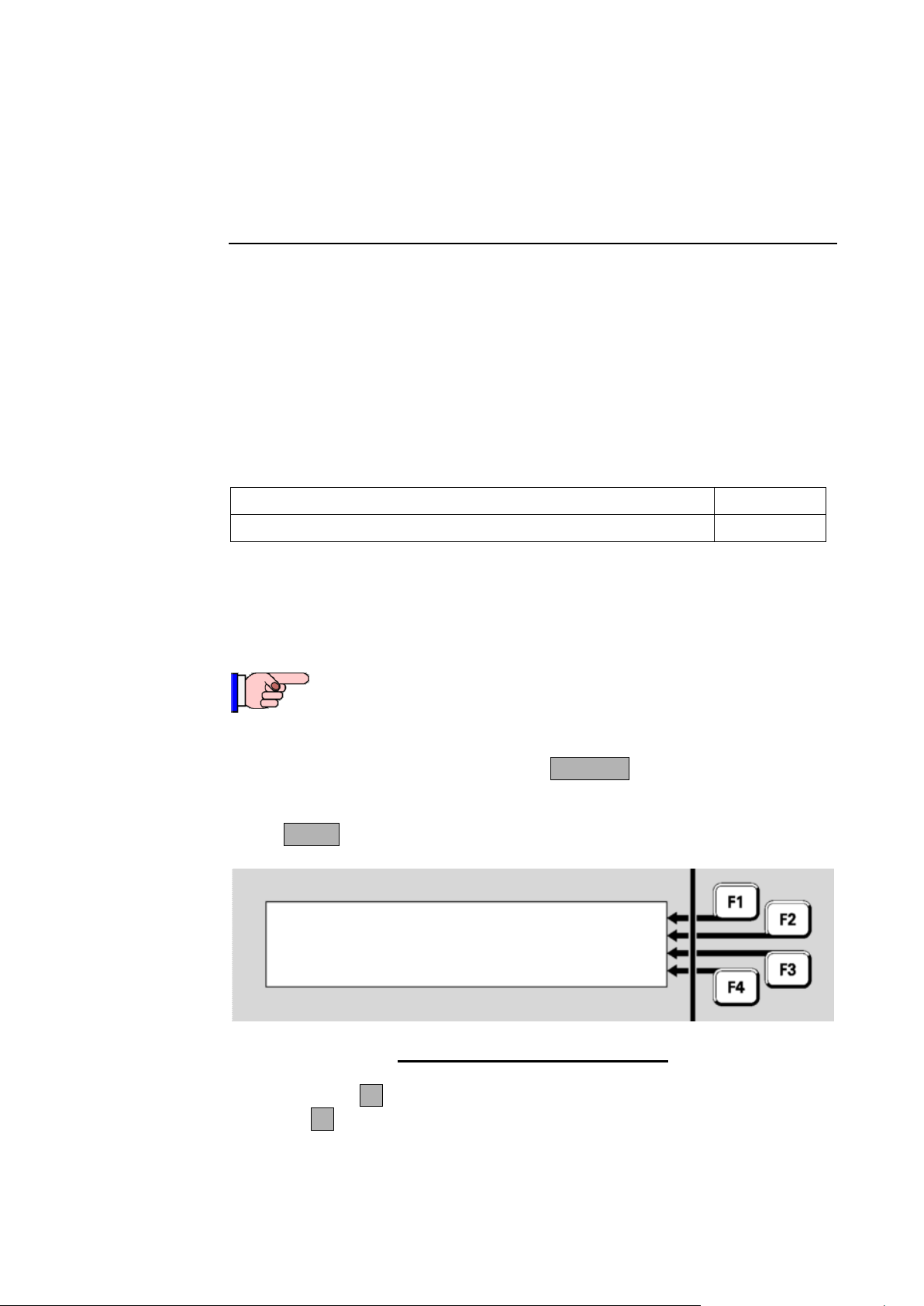
Document: LT0344 Vigilant MX1 Operator Manual
Topic
See Page
Logging On to Access Level 3
7-1
This function requires Access Level 2.
| LOGON
| MX LOOP
| MEMORY
Press MENU for more options |
Chapter 7
Logging On to Access Level 3
Introduction
In this
Chapter
Logging On to Access Level 3
Logging On
AUTO ADD
Most service functions are available at Access Level 2. See Access
Levels on Page 1-11.
Critical service functions are available at Access Level 3 which is entered
on the keypad using a User Code and PIN at Access Level 2.
This chapter describes logging on to Access Level 3.
Refer to the page number listed in this table for information on a specific
topic.
If the MX1 display is not showing one of the base displays (Normal, OffNormal, Fault or the Alarm List), press CANCEL until the base display is
reached.
Press MENU three times to reach the logon option.
Press LOGONF1 to see the logon display. Note that if no option is
shown at F1, the MX1 is already at Access Level 3.
Issue 2.4 8 August 2017 Page 7-1
Fig 7-1 – Menu Options-Third Screen
Page 82
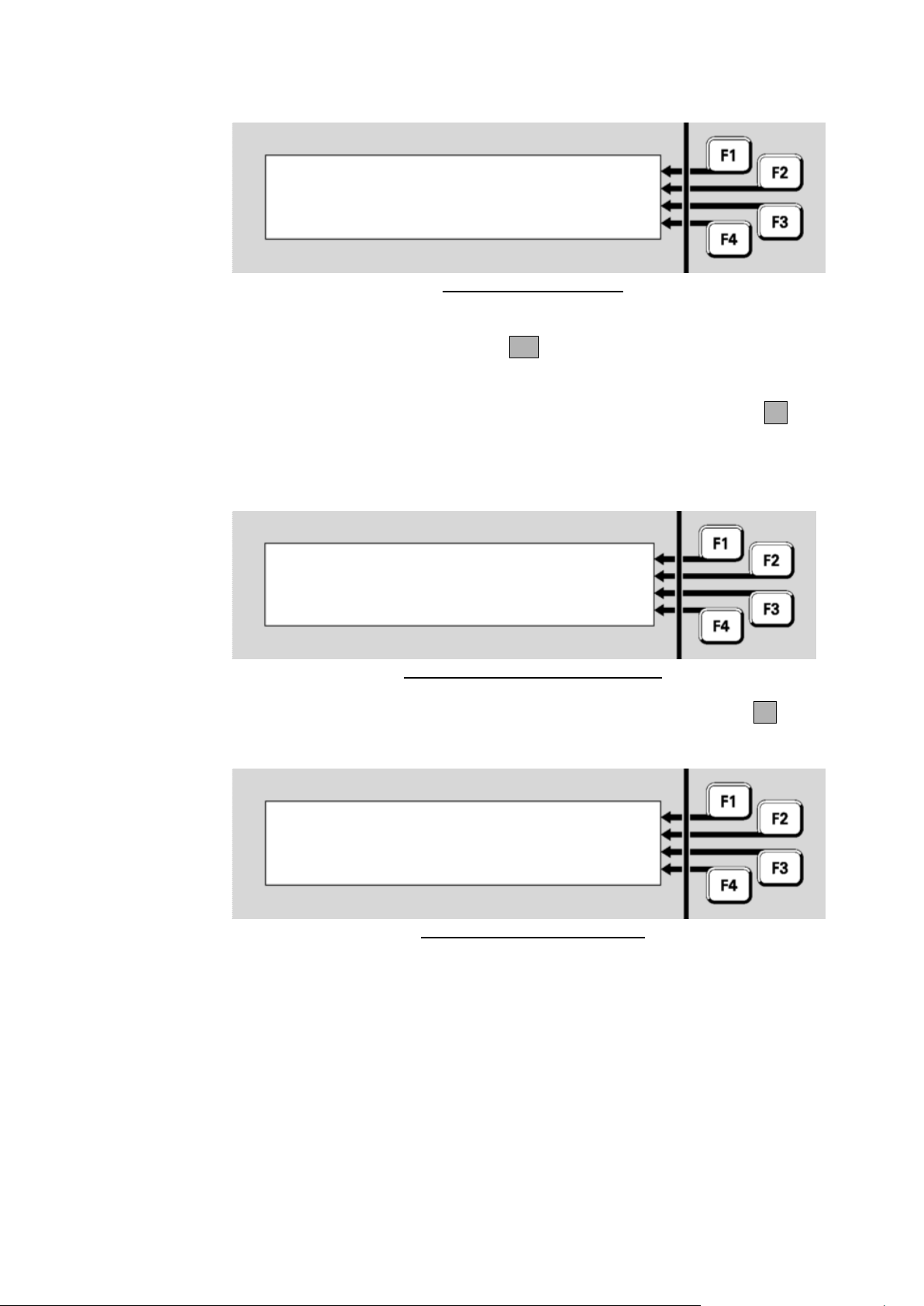
Vigilant MX1 Operator Manual Document: LT0344
Enter user code and pin: |
Code: |
Pin : |
F4 to backspace, OK to finish | <-
Enter user code and pin: |
Code: - Verified - |
Pin : - Verified - |
| <-
|
| MX LOOP
| MEMORY
Press MENU for more options |
Logging Off
AUTO ADD
Fig 7-2 – Log On Display
Using the numeric keypad, enter the single digit user code followed by
the PIN for this user code. Press OK after the PIN is entered.
Each digit of the user code and PIN are represented on the display by an
‘*’ symbol when you enter them. If you mis-key a number, press F4 to
backspace over it, then re-enter the correct number.
If the user code and PIN match, a “verified” display will show briefly:
Fig 7-3 – Successful Level 3 Logon
This will be followed by the Menu display, but with the LOGONF4 option
removed.
Page 7-2 8 August 2017 Issue 2.4
Fig 7-4 – Level 3 Menu Display
You will remain logged on to Level 3 until one of the following happens:
The cabinet door is closed and locked (which operates the door
switch) or the keyboard-enabling keyswitch is switched off.
The door switch is operated manually.
The system is restarted as part of loading a new configuration data
file.
The system is powered down and powered up again.
Ten minutes elapse since the last key is pressed.
Page 83

Document: LT0344 Vigilant MX1 Operator Manual
Topic
See Page
Front Panel Display Test
8-1
Setting System Time and Date
8-2
Power Supply Status and Battery Testing
8-3
MX Loop Status
8-5
System Memory Status
8-7
Test System
8-10
Test Alarm Devices
8-11
Replacing an MX Device
8-12
Buzzer Disable and Mute
8-14
Commissioning Mode (Access Level 3)
8-16
Resetting the System (Access Level 3)
8-17
This function requires Access Level 2.
Chapter 8
Other Service Functions
Introduction
In this Chapter
Front Panel Display Test
Testing the Front Panel Display
This chapter describes other service functions that are available from the
MX1 front panel.
Some of these commands require operator Access Level 3. See Chapter
7 for how to log on to operator Access Level 3.
Refer to the page number listed in this table for information on a specific
topic.
The LCD and indicator lights on the front panel of the MX1 can be quickly
checked for correct operation by using the display test.
If the MX1 display is not showing one of the base displays, i.e., Normal,
Off-Normal, Fault or the Alarm list, press CANCEL until the base display
is reached.
Press MENU to see a set of options.
Issue 2.4 8 August 2017 Page 8-1
Page 84
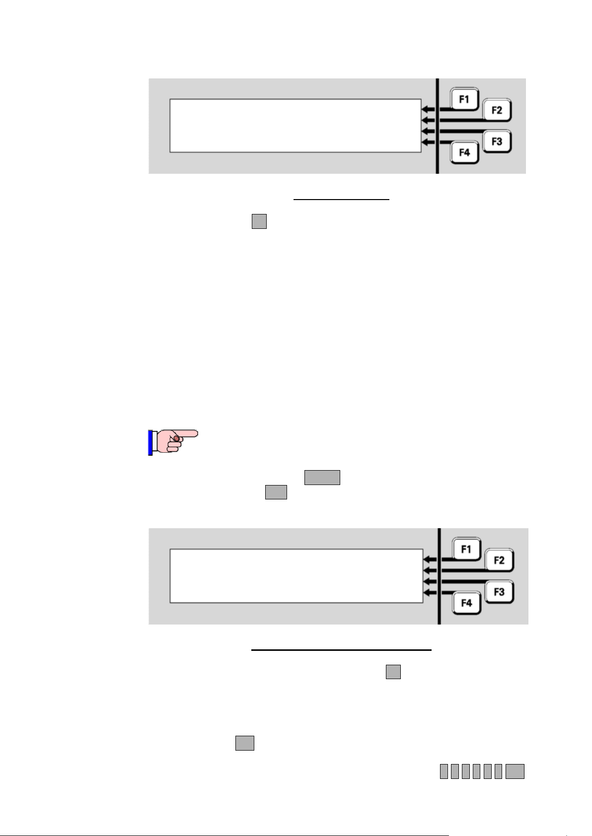
Vigilant MX1 Operator Manual Document: LT0344
|DISP TST
| RECALL
| HISTORY
Press MENU for more options | POWER
This function requires Access Level 2.
Current time is 21:50:13 | CHANGE
Current date is 13/07/07 | CHANGE
daylight saving is Off |
|
Setting System Time and Date
Setting the Time and Date
Setting the Time
Fig 8-1 – Base Menu
Press DISP TSTF1 to start the display test:
All the keypad indicators apart from the zone indicators will light
steadily for the entire test.
Each column of each set of 16 zone indicators will light in sequence,
followed by each row of each set of zone indicators lighting in
sequence.
The LCD will go blank and a solid black horizontal bar will step from
the top row to the bottom of the display.
The buzzer will beep at its quiet and loud volume settings.
At the end of the test, the above menu will be shown again.
From the base display, press MENU twice to see a menu with a Date
option. Press DATEF2 to select the Date/Time menu:
To change the system time, press CHANGEF1. All the digits are set to
zeroes.
Enter the current time in 24-hour format as HHMMSS. Separators
between the hours and minutes, and minutes and seconds, are not
required. Press OK to store the new time and start the clock.
Page 8-2 8 August 2017 Issue 2.4
For example, a time of 1:35:00pm would be entered as 1 3 3 5 0 0 OK
Fig 8-2 – Date And Time Change Menu
Page 85
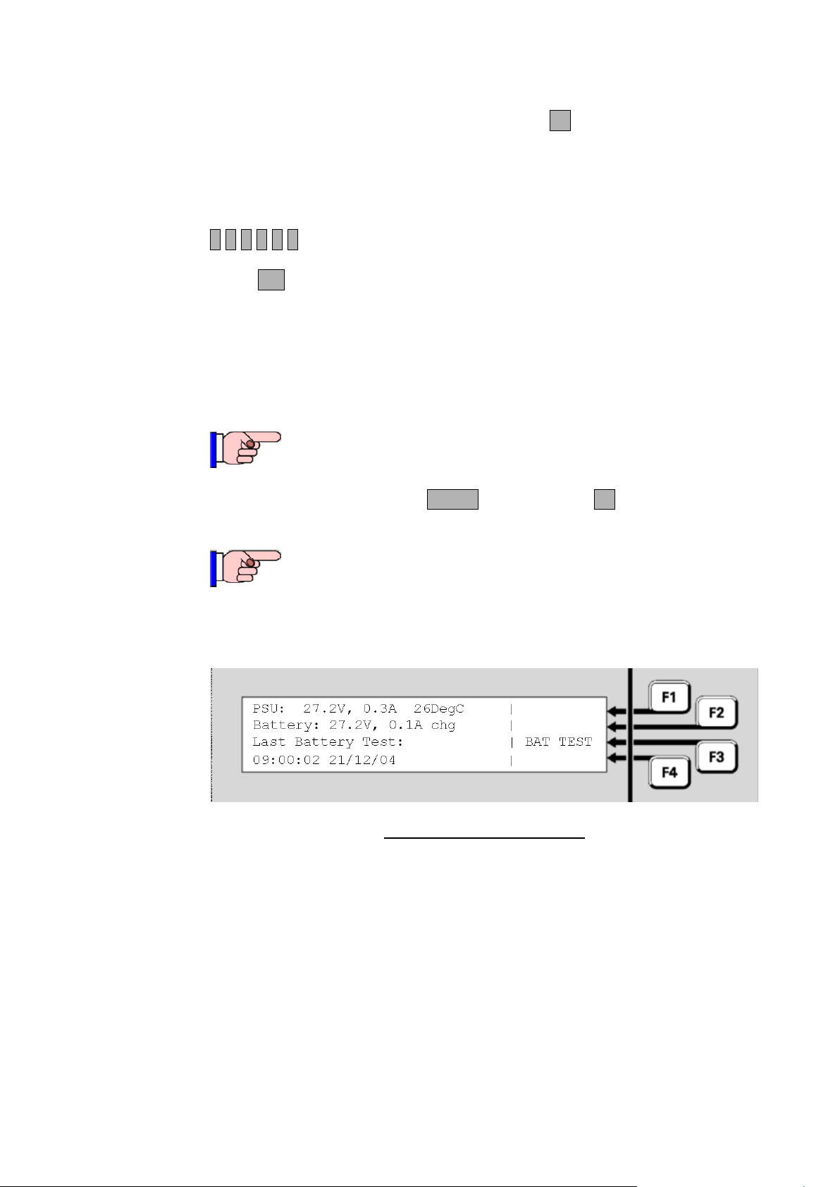
Document: LT0344 Vigilant MX1 Operator Manual
This function requires Access Level 2.
The PSU and battery voltage and current readings are not
calibrated. There may be offsets that become apparent,
especially at low current levels to/from the battery. If accurate
readings are required then suitable voltmeters and ammeters
must be used to obtain the necessary measurements.
Setting the Date
Daylight Saving
Power Supply Status and Battery Testing
To change the system date, press CHANGEF2. All the digits are set to
zeroes.
Enter the day, month and year without separators.
For example, a date of 21 December 2004 would be entered as
2 1 1 2 0 4.
Press OK to store the new date.
The Daylight Saving status is determined automatically by the current
date and the site’s configuration.
From the base display press MENU, then POWERF4 to view the Power
Supply Status.
Fig 8-3 – Power Supply Status
The following information is displayed:
PSU: is the power supply output voltage and current. The voltage
reading may periodically fluctuate slightly when a Battery Connection
check is made. Note that the current includes both battery-backed
and non-battery-backed loads.
Temperature: is the approximate temperature in the MX1 cabinet
in C.
Battery: is the voltage and current flowing at the battery terminals
of the controller. The current is shown as chg for charge current
Issue 2.4 8 August 2017 Page 8-3
flowing into the battery, and dis for discharge current flowing out of
the battery.
Page 86

Vigilant MX1 Operator Manual Document: LT0344
The manual battery test function does not qualify as a
monthly battery test to the requirements of NZS 4512.
Battery test: Long Battery Test |
Battery: 27.3V, 0.2A dis |
Last battery test: |
Test in Progress. 39 mins left |STOP TST
This function requires Access Level 2.
Automatic Battery Tests
Last Battery Test: shows the time/date and result of the most
recent battery test (manual or automatic).
Pressing BAT TESTF3 will start a manual battery test. The duration of
this battery test is determined by the system configuration (usually 1
minute). The test will not start if the mains power is off, or a battery test
(automatic or manual) is already in progress.
During the battery test, a progress indication will be displayed showing
the number of minutes remaining for the test. A manual battery test
cannot be cancelled once under way. The battery test lowers the battery
charger voltage (to 22-23V) so that the panel and loads are powered by
the battery.
MX1 also carries out automatic battery tests. The scheduling and
duration of these tests are determined as part of the MX1 configuration,
and require no operator intervention under normal conditions.
By default the test will start at 9am on each working day and last for 60
minutes.
If the battery fails the automatic test the FAULTS indicator will light and
the failure will be logged in the Event History (see Chapter 4). Where
available, the service company will be notified.
The automatic battery test can be cancelled as follows.
From the base display press TESTS, INITIATEF4 , then MENU,
BATTERYF3 to view the Battery Test status screen.
Fig 8-4 – Battery Test Menu
If the automatic test is running, as indicated by a Battery Test status of
‘Long Battery Test”, press STOP TESTF4 to stop the test.
Page 8-4 8 August 2017 Issue 2.4
Page 87

Document: LT0344 Vigilant MX1 Operator Manual
Equipment : 8 Ver 2.00 |
MX Loop : 40.7V, 0.0A | PREV
Return : 40.3V | NEXT
| DEVICES
MX Loop Status
Viewing Loop Status
IR CTRL
From the base display press MENU three times then MX LOOPF2 to
view the MX Loop Status.
Equipment: shows which MX loop is being viewed. 1 is the on-
board loop and 2 onwards are the optional MX Loop Cards. The
firmware version for each MX Loop Card will be included. Press
PREVF2 or NEXTF3 to switch between loops.
MX Loop: is the voltage and current being fed to the loop wiring.
Return: the voltage at the return end of the loop.
Normally the power is fed via the AL terminals and the loop return
voltage is measured at the AR terminals. In this situation the points
described below will all be normal.
Under fault conditions, the power feed may be switched to the AR end
(for a short circuit at the AL terminals), or feed via both ends (for an open
circuit in the loop, or a short circuit between two short circuit isolators).
Fig 8.5 shows a typical situation. The power feed is applied to the start
of the loop, which is drawing only a light load current. The voltage at the
end of the loop is being monitored to detect any breaks in the wiring.
If power is being fed to the AR side, the Return voltage displayed will be
0V. If the loop is drawing too much current, the MX Loop voltage display
will also be 0V. A more detailed assessment of the MX Loop condition
can be gained from the presence of these points in the fault list (refer to
Chapter 11 (“Equipment Point Descriptions”) for details).
MX Loop Left S/C – is in Fault if there is a short circuit between
the AL+ and AL- terminals.
MX Loop Right S/C – is in Fault if there is a short circuit between
the AR+ and AR- terminals.
MX Loop Open Circuit – is in Fault if there is an open circuit in
the loop wiring. Note that an activated short circuit isolator will also
register as an open circuit fault.
MX Loop Overload – is in Fault if too much current is being drawn
by the MX Loop. The normal capacity for each loop is 1A.
Press IR CTRLF1 to access the Infrared commands. Note this
command requires operator Access Level 2.
Issue 2.4 8 August 2017 Page 8-5
The DEVICESF4 command allows the loop to be scanned for all MX
Fig 8-5 –
MX
Loop Status
Page 88
Vigilant MX1 Operator Manual Document: LT0344
IR Control
Scanning for MX Devices
devices that are present, or to identify where a break may be. See
Scanning for MX Devices page 8-6.
From MX Loop Status display press IR CTRLF1 to access the IR
(Infrared) commands.
This command requires operator Access Level 2.
The 850 detectors support infrared (IR) communication with the 850EMT
MX service tool. This allows technicians to carry out functions such as
programming the detector’s device number, reading its parameters and
status, using an IR connection while standing some distance from the
detector.
Before you can communicate with a detector using IR the loop the
detector is connected to must be put into IR mode. Select the required
MX loop (see Figure 8-5) and then press IR CTRLF1. This will show
the IR controls – see Figure 8-6a.
Fig 8-6a –
MX
Loop IR
Pressing IR ONF1 will activate IR mode on the currently displayed
loop.
Pressing IR OFFF1 will deactivate IR mode on the displayed loop.
Pressing All ONF2 will turn on IR mode on all loops.
Pressing All OFFF3 will turn off IR mode on all loops.
Pressing << BACK F1 will return to the previous display (Figure 8-5).
IR mode automatically times out after 8 hours if it is not
turned off via the menu.
A detector in IR mode cannot communicate with both the
panel and the 850EMT service tool at the same time.
Therefore while a detector is communicating with the service
tool it is ‘off line’ and can no longer send alarms to the MX1.
After 1 minute the detector will go into Device-fail at the MX1.
The DEVICESF4 command on the MX Loop Status screen can be
used to scan that MX Loop for all MX devices present – even if the MX1
has no, or a different, datafile present.
This can be used, for example, at installation time to check all devices
have been installed, wired and addressed correctly, even without any
datafile having been programmed into the MX1.
Page 8-6 8 August 2017 Issue 2.4
Page 89
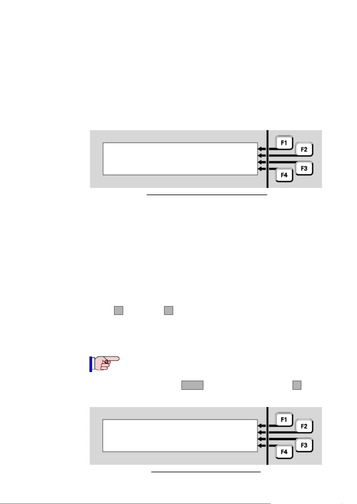
Document: LT0344 Vigilant MX1 Operator Manual
This function requires Access Level 2.
|
Select memory area to display
status | DATAFILE
| KEYPAD
| PROGRAM
System Memory Status
Viewing System Memory Status
|
P000:
P001:814CH LR
P002:814CH LR
P003:814CH LR
|
PREV
|
|
NEXT
It can also be used if a foreign device is found (P241/26/5 goes into fault)
by looking through each loop for FRGN devices, or when a loop break is
present to identify those devices on each side (L or R) of the break.
The MX1 will poll every address from 0 to 255 (note addresses 0 and
251-255 are not supported by the MX1 for configured devices) and
attempt to identify the type of device present (this may fail if two or more
devices are present at the same address).
Figure 8-6b shows an example resulting display.
Fig 8-6b – Example
MX
Loop Scan Display
Each screen will show 4 addresses (e.g., 0, 1, 2, 3) plus:
The device type – blank if no device present at that address.
L, R, or LR to indicate the device is visible from the left side, right side
or both left and right side of the loop.
DUP if two or more devices are present at the address.
MISM if the device type does not agree with the type programmed in
the MX1’s datafile.
FRGN if the device is not programmed at all in the MX1’s datafile.
UNDR if the address is 0 (under-addressed).
OVER if the address is 251-255 (over-addressed).
NEXTF3 and PREVF2 can be used to step through the various
addresses.
From the base display press MENU three times then MEMORYF3 to
view the System Memory Status menu.
Issue 2.4 8 August 2017 Page 8-7
Fig 8-7 – System Memory Status Menu
Page 90
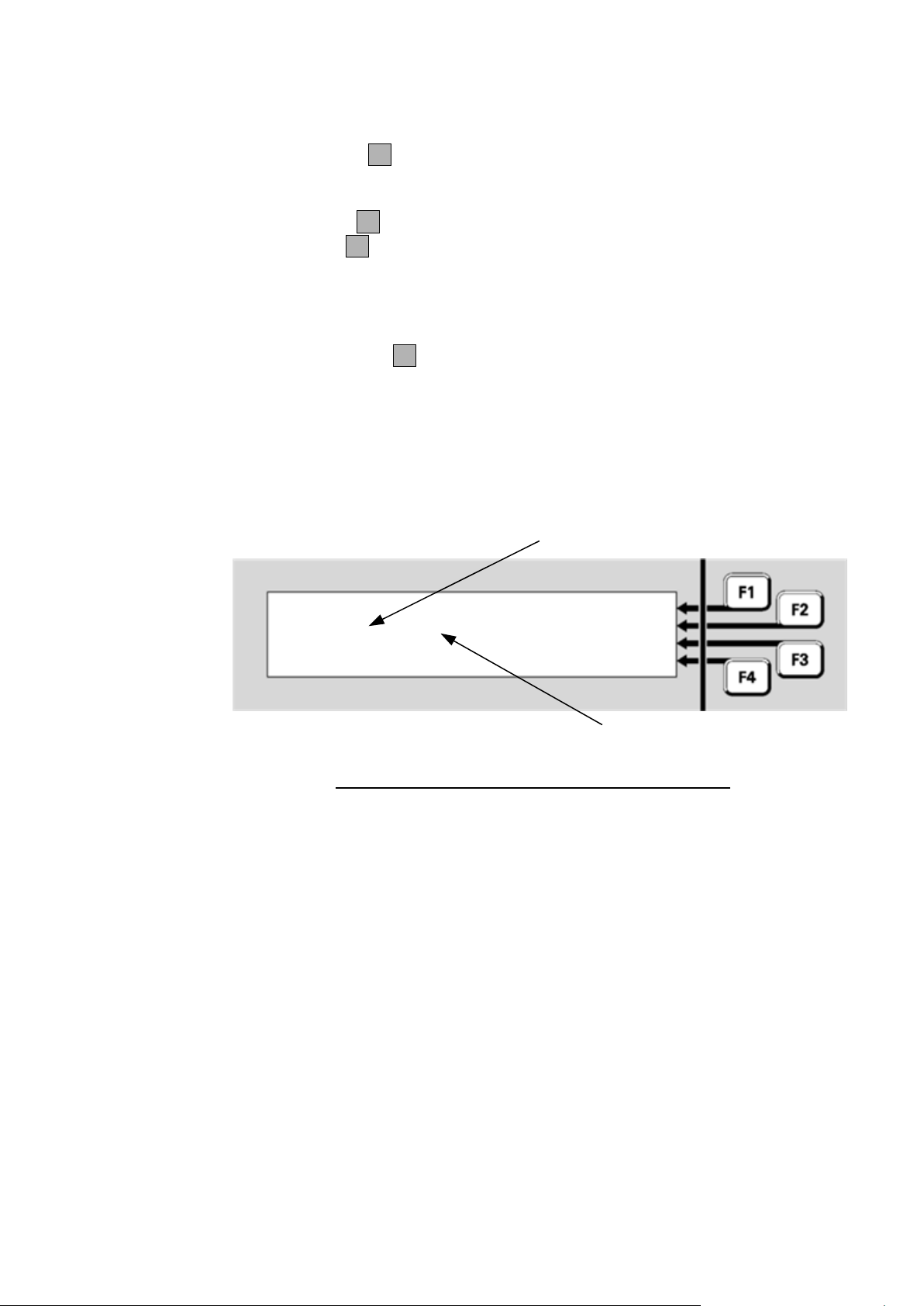
Vigilant MX1 Operator Manual Document: LT0344
Datafile1: Active | ACTIVE
CRC:nnnnnnnn cccc | FILE2
Datafile: SiteConfig | PROGRAM
Written: 22 Aug 2006 09:31:56 | KEYPAD
Even where the datafiles contain the same
programmed information they will show
different CRC values here
Identical programmed configurations will
show identical values here
Viewing
Datafile
Status
Menu options are:
DATAFILEF2 displays information about the two site-specific
configuration data files. There are two copies of the configuration file;
only one of these will be active at any time.
PROGRAMF3 displays information about the controller firmware.
KEYPADF4 displays information about the LCD/keyboard firmware.
Note the firmware version for each MX Loop Card is shown on the MX
Loop Status screen Figure 8-5.
Press DATAFILEF2 to show the status of the first copy of the sitespecific configuration.
The filename, date and CRCs of the configuration files stored in the MX1
can be viewed. This will also show which configuration files are active.
Fig 8-8 – Site-Specific Data Display – Datafile 1 Active
Page 8-8 8 August 2017 Issue 2.4
Page 91

Document: LT0344 Vigilant MX1 Operator Manual
Program Memory |
Version: V1.30 |DATAFILE
CRC: nnnnnnnn Normal |
|KEYPAD
Viewing Controller Firmware Status
The following information is displayed:
Datafile1: this shows the number of the data file and Active if this
configuration file is being used or Disabled if not being used.
CRC: this shows two values. The first is the integrity checksum for this
data file, followed by the CRC for the configuration file (the same as
displayed by SmartConfig). The correctness of the integrity
checksum controls a system point, Database 1 CRC, which will
produce a fault indication if the checksum is not correct. Note that the
integrity checksum shown on line 2 for each data file will be different
even when both data files are loaded from the same SmartConfig
data file. The second value shows the “invariant” configuration data
file CRC. This is the same value as calculated and displayed by
SmartConfig using the Show CRC command, so these can be
compared to confirm that the configuration data file in the MX1 is the
same as that in SmartConfig.
If the same SmartConfig data file is loaded into both data file
locations, the invariant CRC value will be the same for each of the
data files.
Datafile: the name of the SmartConfig file when it was downloaded
into the MX1 by SmartConfig.
Written: the time and date on the PC when the configuration was
last changed before being downloaded. Note that random characters
may appear in the time and date fields when there is no valid datafile.
Menu options are:
ACTIVEF1 is an Access Level 3 command and will appear only if
Access Level 3 is enabled. It forces this data file to become the
active copy. A confirmation prompt is displayed. Press OK to restart
the system and switch to this data file. If this data file is not valid, the
system will automatically switch back to the other data file.
FILE2F2 switches to the equivalent status display for the second
data file.
PROGRAMF3 displays information about the controller firmware.
KEYPADF4 displays information about the LCD/keyboard firmware.
From the System Memory Status menu, press PROGRAMF3 to show
the status of the controller firmware.
Issue 2.4 8 August 2017 Page 8-9
Fig 8-9 – Controller Firmware Display
Page 92
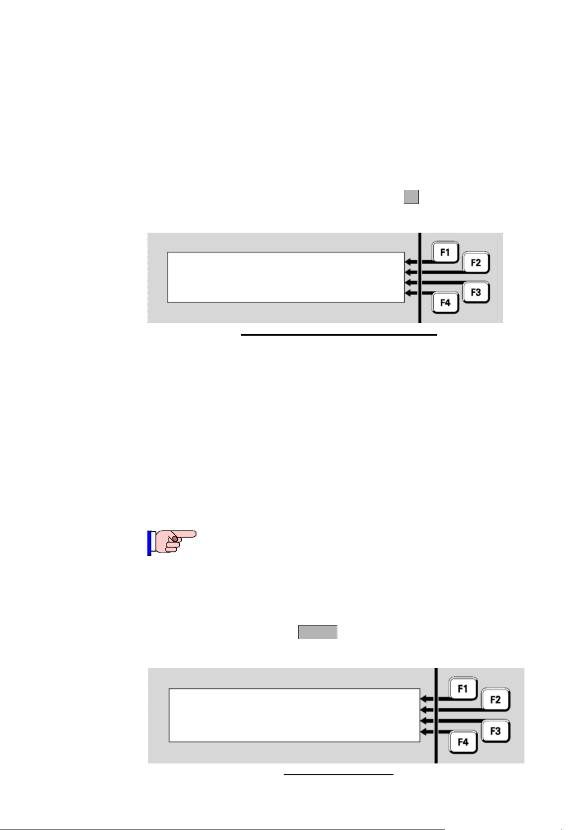
Vigilant MX1 Operator Manual Document: LT0344
Keypad |
Version: n.nn |DATAFILE
Expected CRC: nnnn | PROGRAM
Actual CRC: nnnn |
This function requires Access Level 2.
Viewing Keyboard Firmware Status
Test System
Press F1 to search for |SEARCH
|
Press F4 to initiate a test |INITIATE
active tests. |
The following information is displayed:
Version: is the version of the controller firmware. This is also shown
in the base display when the system is normal.
CRC: the most recently calculated integrity checksum for the controller
firmware and the correctness of the result. This checksum status
controls a system point (241.27.3 Firmware CRC), which will produce
a fault indication if the checksum is not correct.
From the Memory Status menu, press KEYPADF4 to show the status of
the LCD/keyboard firmware.
Fig 8-10 – LCD/Keyboard Firmware Status
The following information is displayed:
Version: is the version of the keyboard firmware. This is also shown
briefly on the LCD when the system powers up.
Expected CRC: the correct value for the integrity checksum for the
keyboard firmware.
Actual CRC: the actual calculated checksum for the keyboard
firmware. This checksum status controls a system point (243.1.6
Keypad Firmware CRC), which will produce a fault indication if the
actual checksum does not match the expected value.
The Test System command allows the MX1 firmware version, firmware
CRC, and the two configuration datafile CRCs, to be viewed on one
screen. This allows easy recording and checking.
From the base display press TESTS, which will show the following
screen.
Page 8-10 8 August 2017 Issue 2.4
Fig 8-11 – Tests Screen
Page 93
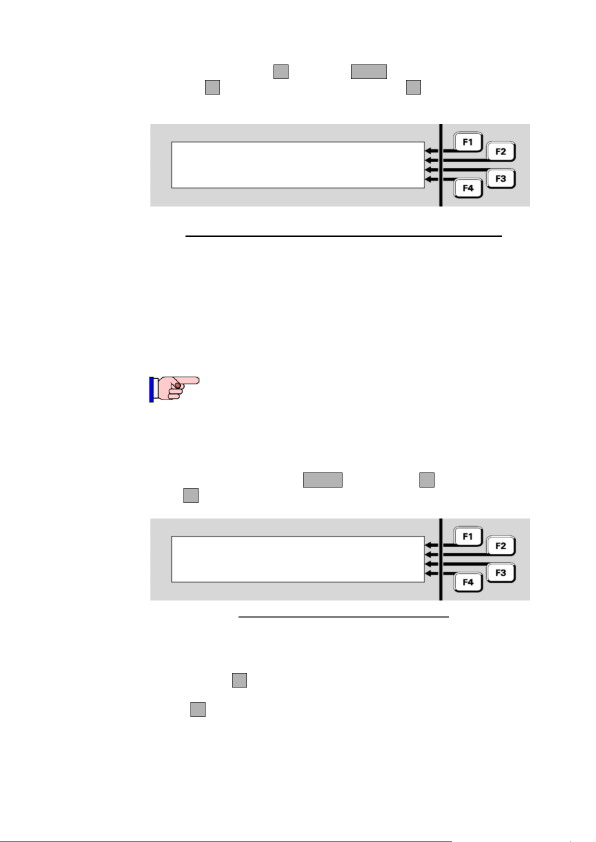
Document: LT0344 Vigilant MX1 Operator Manual
MX1 Vv.vv
Firmware CRC: xxxxxxxx
Config 1 CRC: xxxxxxxx yyyy
Config 2 CRC: xxxxxxxx yyyy
This function requires Access Level 2.
Alarm Devices Test: | START
Inactive |
|
|
Test Alarm Devices
Press the INITIATEF4 option and MENU twice so that a
SYSTEMF1 option is shown. Press SYSTEMF1 to show the following
screen.
Fig 8-12 – Tests System Screen Shows Firmware and Config CRCs
The top line shows the MX1 Controller firmware version, Vv.vv. The
second line shows the firmware CRC. The third and fourth lines show
the internal checksum (xxxxxxxx) and CRC (yyyy) for the two
configuration datafiles. The CRC of the datafiles is the CRC as shown by
the SmartConfig Show CRC command and can be used to confirm the
datafiles are identical or the same as the file on the PC.
The Test Alarm Devices command allows all the alarm devices to be
operated simultaneously, for example, during a trial evacuation of the
building. The alarm devices operate until the test is stopped.
From the base display press TESTS, INITIATEF4 and press ALARM
DEVF3 so the alarm devices test status screen is shown.
This shows the status of the test (Inactive or Active) and allows the test
to be started (if the test is inactive) and stopped (if the test is active).
Press STARTF1 to initiate the test – all alarm devices will operate
unless they have been disabled. Conduct the test and then press
STOPF4 when complete.
The test can also be started by OpOn testing point 241.1.0 (the Alarm
Devices point) and stopped by resetting this point.
Issue 2.4 8 August 2017 Page 8-11
Fig 8-13 – Alarm Devices Test Status Screen
Page 94

Vigilant MX1 Operator Manual Document: LT0344
Device X.XXX in Device Fail
1 unaddressed device present
Press F4 to address device 255 to XXX
Replacing an MX Device
One At A Time Re-Addressing
From time to time it may be necessary to replace an MX loop device with
a new one. When supplied, new MX devices are factory set to address
255. This section describes two methods to install and automatically readdress replacement MX devices.
From the base display press MENU three times, then press
AUTOADDF4 to show two choices:
OneAtTmeF1 – “One at a Time” – allows one device to be
replaced at a time by removing that device, fitting the appropriate
replacement, then re-addressing the replacement from the MX1 front
panel.
MultipleF2 – allows multiple devices to be disabled from the
front panel, then each device to be replaced (one at a time) and for
the replacement to be automatically re-addressed when it is fitted.
This allows multiple devices to be replaced in one trip away from the
MX1.
This method can be used when
- a single addressable device is to be replaced, and
- the replacement device is of the same type, and
- the replacement device is unaddressed (i.e., set to the factory
default address of 255).
Remove the device to be replaced (note that this may create a device fail
fault) and fit the replacement unit. Press OneAtTmeF1 at the AutoAdd
menu. This will result in one of the following displays – Figures 8-14 – 8-
18.
Figure 8-14 shows the device that has been removed and that the
replacement device has been recognised and is ready to be
programmed. Press F4 to program the replacement device with the
missing device’s address. Once done, the device-fail fault on the point
should clear, and affected zones can be reset to clear their faults.
Repeat the process for additional devices needing replacement.
Page 8-12 8 August 2017 Issue 2.4
Fig 8-14 – Device Programming Menu
Page 95
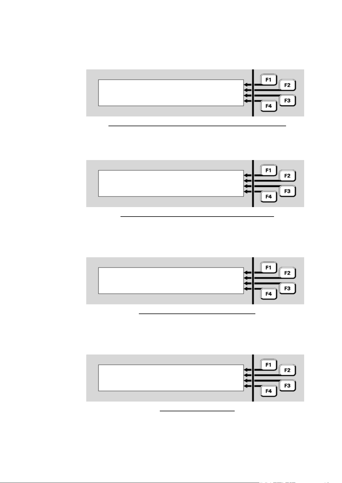
Document: LT0344 Vigilant MX1 Operator Manual
No device in Device Fail
No unaddressed device present
More than 1 device in Device Fail
1 unaddressed device present
Device x.x in Device Fail
No unaddressed device present
Device x.x in Device Fail
Mismatched unaddressed device
If the Auto-Addressing function does not find all of the required conditions
met, one of the following displays (Fig 8-15, 8-16, 8-17 or 8-18) will be
shown to indicate the cause.
Fig 8-15 – Device Programming Menu – No Devices in Device Fail
There must be one (and only one) device in device fail on that MX loop
for the re-addressing function to be used.
Fig 8-16 – Device Programming Menu – Multiple Devices
The OneAtTme function can be used only when there is a single device
in Device Fail.
Fig 8-17 – No Unaddressed Device Present
Ensure that the new device has been correctly fitted to its base, or wired
into the loop, that it has not already been programmed, and that no other
device programmed to address 255 is installed on the loop.
Check that the replacement device is of the same type as the removed
one. The OneAtTme function can program only replacement devices
that are of the same type as the device they are to replace.
Issue 2.4 8 August 2017 Page 8-13
Fig 8-18 – Device Mismatch
Page 96
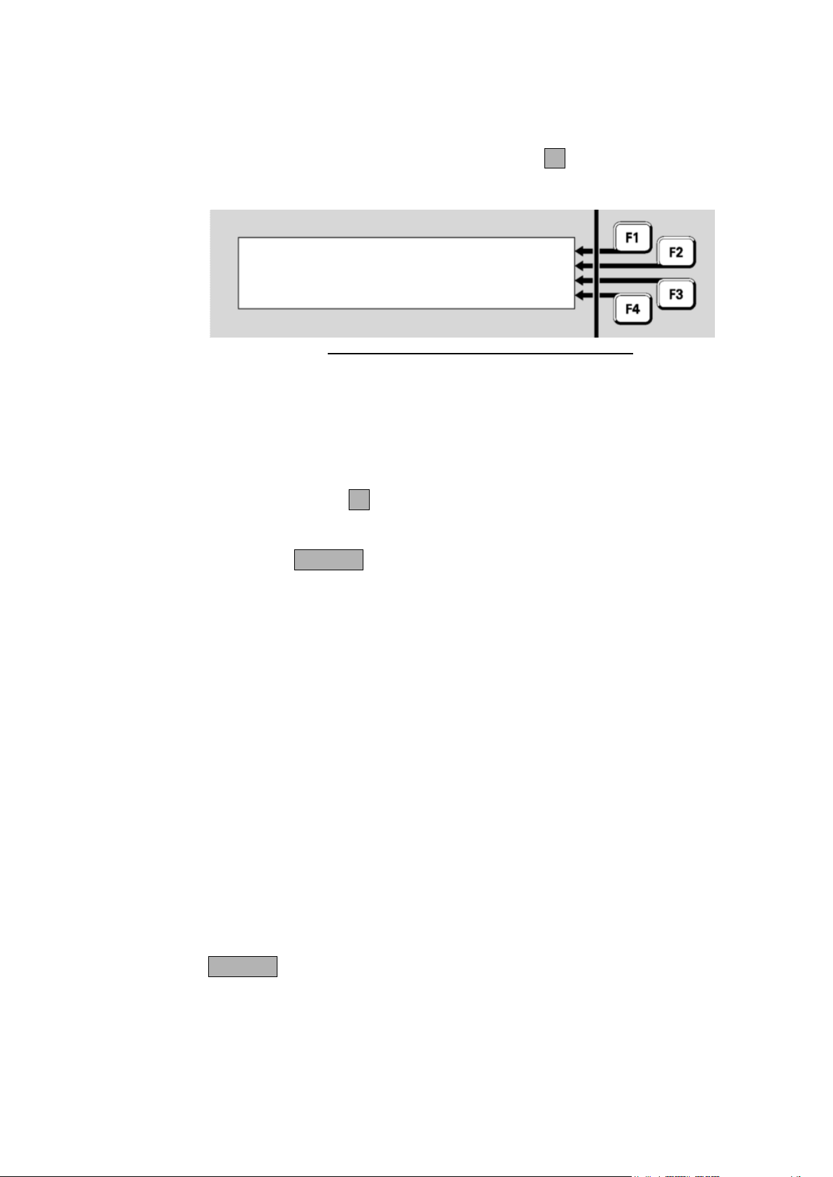
Vigilant MX1 Operator Manual Document: LT0344
Multiple Device Re-Addressing
Buzzer Disable and Mute
Disable pts for readdressing
| | 000 pts readdressed
|
SELECT
Press CANCEL to exit
|
000 pts disabled
The Multiple addressing method allows multiple devices to be disabled,
and then in a single trip away from the MX1 panel, replace each device
(one at a time) and have the replacement automatically re-addressed to
match the removed one. Press MULTIPLEF2 from the AutoAdd menu.
This will show a screen like Figure 8-19.
Fig 8-19 – Multiple Device Re-Address Display
This screen will show the total number of MX Devices that have been
disabled (at least sub point 0 must be disabled for the device to be
included in this count). It will also show the number of devices that have
been re-addressed, incrementing as each device is removed and a
replacement re-addressed.
Use the SELECTF1 command to select those devices to be disabled
and thus allow re-addressing. This command operates the same as
Disabling or Enabling a point from a Recall Point Status display – Page
6-9. Press CANCEL to return to the Multiple Device Re-Address screen
Fig 8-19.
Then proceed around the premises, replacing each selected device with
a new device of the same type. When the new device is re-addressed its
LED will turn on for 5 seconds and then start normal polling. Note this
will not work if:
- the replacement device is not the correct type.
- the replacement device is not address 255.
- more than one device is not present on the loop (Device Fail).
- or the original device had not been disabled.
After all required devices have been replaced, recall each one (e.g., use
the Disables command) and check that no device fail condition is
present, then re-enable it. Also reset any zone faults, then check that
point 241.26.5 is not in fault. This could happen if a replacement device
is not re-addressed and so is seen as a foreign device.
Note this screen will not revert to the base display on a timeout or if the
outer door is closed (allowing the cabinet door to be locked while
replacing devices) or keyboard disabled, so it is necessary to press
CANCEL to exit this re-addressing mode.
Two commands are available to stop the alarm and fault buzzer from
sounding - for example, during commissioning, annual surveys, or fault
Page 8-14 8 August 2017 Issue 2.4
Page 97
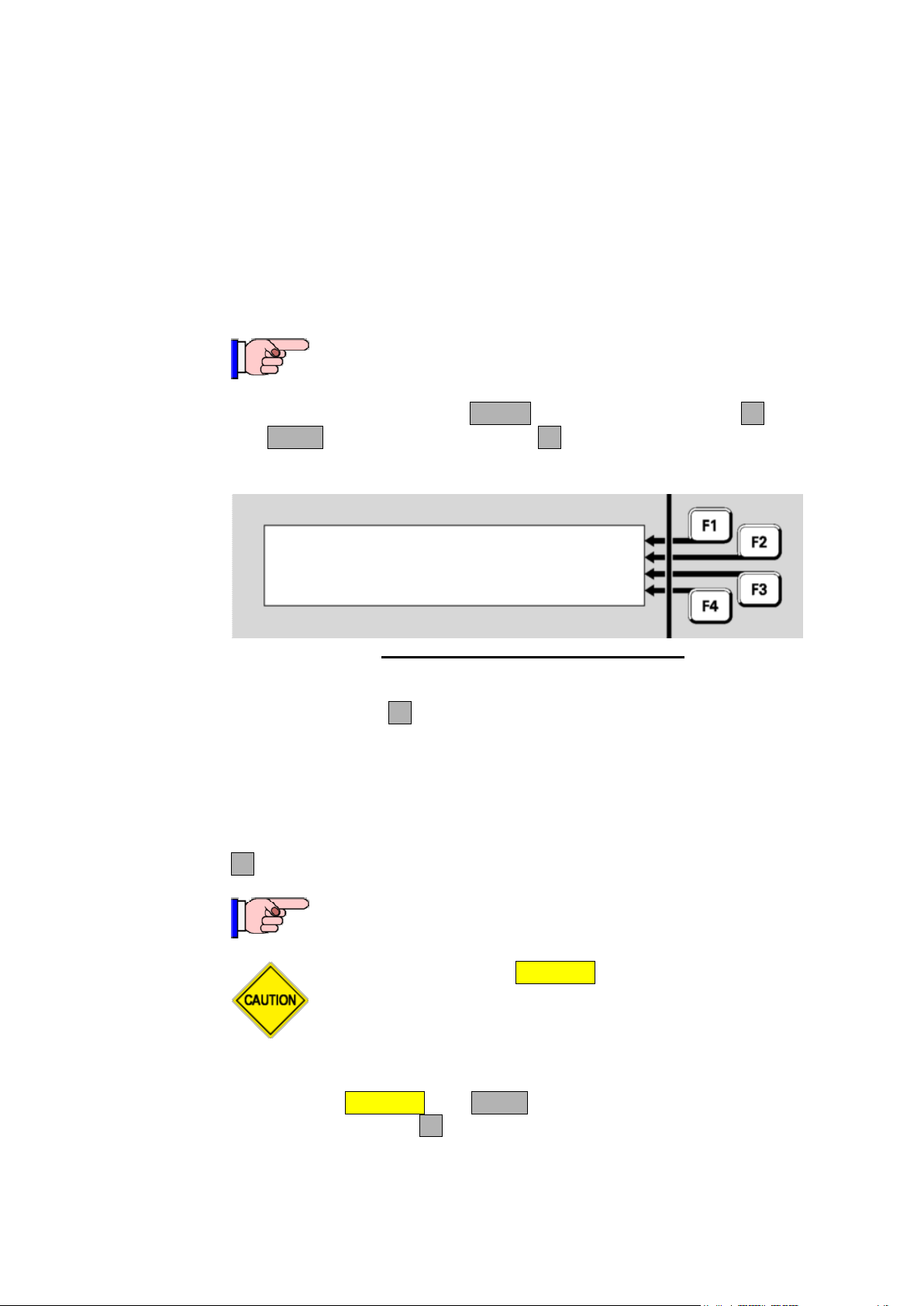
Document: LT0344 Vigilant MX1 Operator Manual
This function requires Access Level 2.
Buzzer status:
Enabled
Press F4 to temporarily mute buzzer
This function requires Access Level 3.
Do not press the f.b.p. DISABLE control when the Alarm List is
being shown unless the intent is to disable the displayed zone
in alarm.
Temporary Buzzer Mute
Buzzer Disable (Access Level 3)
finding. Using these at either the MX1 panel or the remote FBP will
disable/mute the buzzers at both units, except for keypress beeps.
Buzzer Mute: This is a temporary buzzer mute function and lasts for
24 hours or until the mute is cancelled – manually or by power down
or restart of the MX1. Note that this will stop the buzzer from
sounding for any alarms and fault conditions.
Buzzer Disable: This function is an Access Level 3 command and
lasts for as long as the buzzer is disabled.
From the base display press TESTS then select INITIATEF4 option
and MENU to show the BUZR DISF1 option. Press this to display the
Buzzer status screen.
Fig 8-20 – Temporary Buzzer Mute Status
This will show the Buzzer status as Enabled, Muted or Disabled. When
it’s Enabled, press F4 to temporarily mute the buzzer for 24 hours, or
until earlier cancelled.
Once the buzzer has been temporarily muted it will appear in the tests
recall as Point 243.1.14 in a TestOp status, which can be cancelled by
resetting this point.
F4 can be used to enable the buzzer if it is disabled or muted.
Log on to Access Level 3 if not already (see Section 7). From the base
display press DISABLE then MENU (twice if any Disables are present) to
show the BUZR DISF1 option. Press this to show the buzzer status
screen.
Issue 2.4 8 August 2017 Page 8-15
Page 98
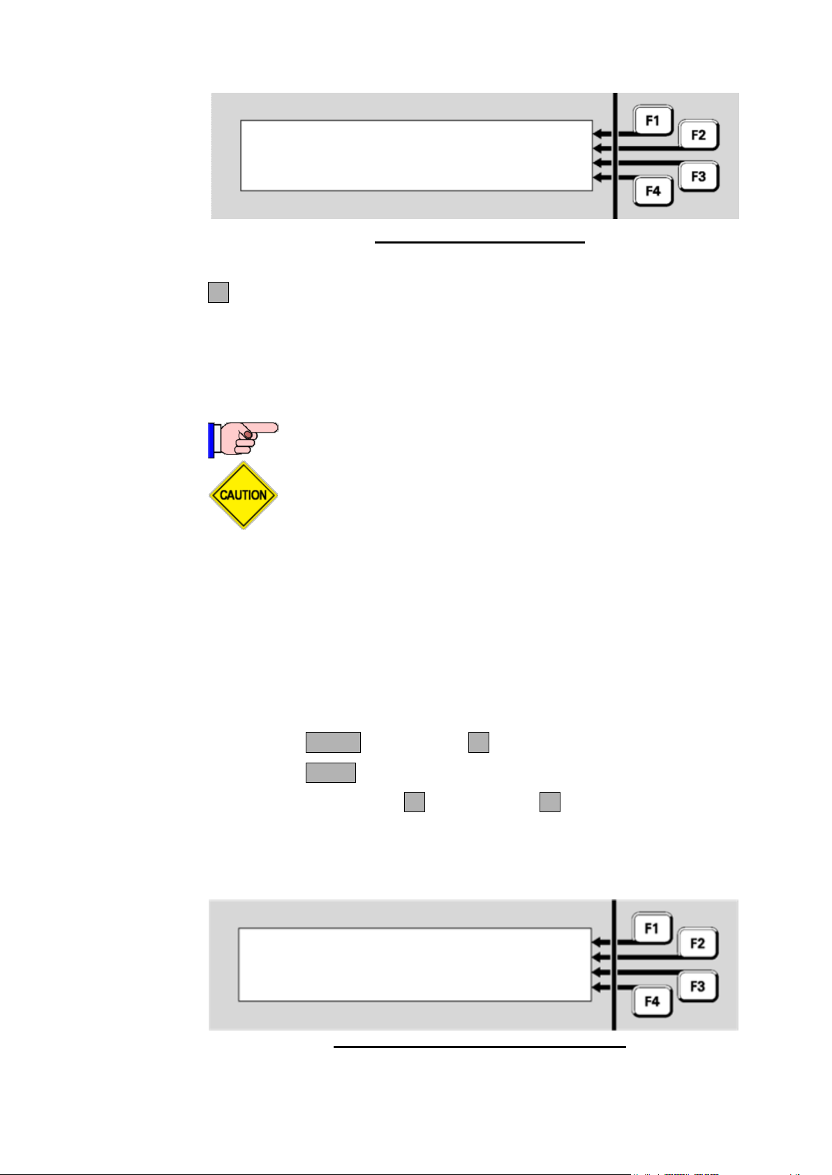
Vigilant MX1 Operator Manual Document: LT0344
Buzzer Status:
Enabled
Press F4 to DISABLE buzzer
This function requires Access Level 3.
During Commissioning Mode the system may produce
unexpected nuisance alarms as the processing algorithms for
detectors are bypassed, making them sensitive to smoke, etc.
Commission Mode is Active
120 Minutes Remaining
STOP
EXTEND
|
|
|
|
Commissioning Mode (Access Level 3)
Fig 8-21 –Buzzer Disable Status
This will show the Buzzer status as Enabled, Disabled or Muted. Press
F4 to enable or disable the buzzer. Once the buzzer has been disabled
it will appear in the Disables List (point 243.1.14) and can be re-enabled
from there.
Commissioning Mode reduces the time required for in-situ detector tests
and setup procedures to be performed, by removing the processing
algorithms.
The acknowledgement times for AAF and AIF are reduced to 10 seconds
and the search times for AAF, ADF and AIF are reduced to 30 seconds.
To initiate Commissioning Mode, login to Access Level 3 and use the
following procedure.
1. Press TESTS, INITIATEF4.
2. Press MENU until “COMMISSN” appears in the display.
3. Press COMMISSNF2, then STARTF1. The following LCD
indication should appear, a countdown from 120 minutes begins
and point 241.27.10 will be put into TestOp state. Commissioning
mode will end when this countdown is complete or it is manually
stopped.
Page 8-16 8 August 2017 Issue 2.4
Fig 8-22 – Active Commission Mode Display
Page 99
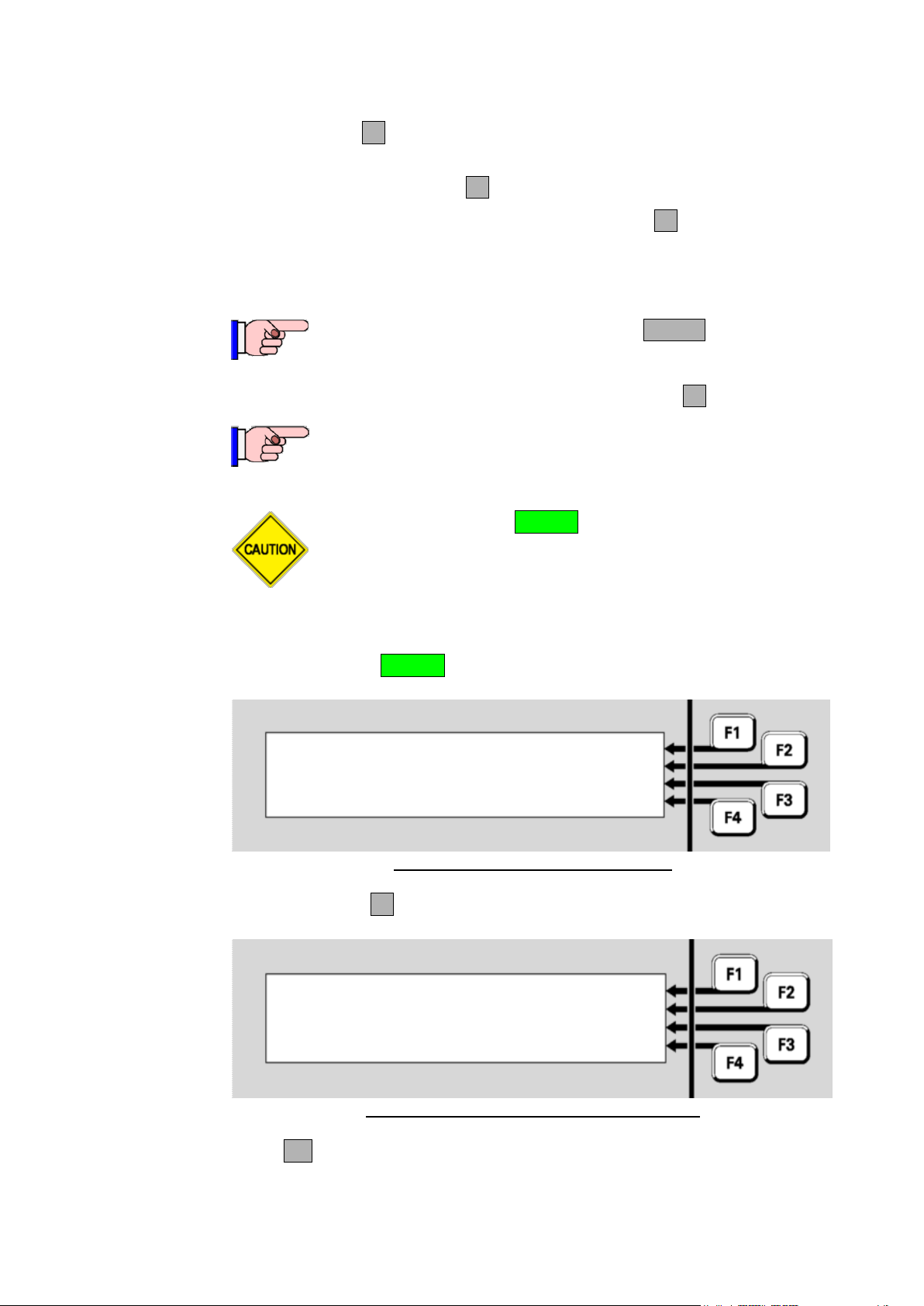
Document: LT0344 Vigilant MX1 Operator Manual
You cannot stop the test by pressing TESTS and then
attempting to Reset or Disable the point (241.27.10)
indicating that Commissioning Mode is active. You need to
repeat the steps above and press STOPF4.
This function requires Access Level 3.
Do not press the f.b.p. RESET control when the Alarm List is
showing unless the intent is to reset all zones in alarm.
Select an item to reset | ZONE
| POINT
| SYSTEM
|
Reset system?
Press OK to confirm
or CANCEL for no action
Resetting the System (Access Level 3)
4. If the message “Commission Mode is Stopped” appears, press
STARTF1 to start Commissioning Mode again.
5. To extend Commissioning Mode by returning the countdown to
120, press EXTENDF3.
6. To end Commissioning Mode, press STOPF4.
The MX1 operation can be restarted from the LCD. This function requires
Access Level 3. Refer to Section 7 to log on to level 3. From the base
display, press the RESET key.
Fig 8-23 – Access Level 3 Reset Menu
Press SYSTEMF3 to see the following prompt;
Fig 8-24 – System Reset Confirmation Screen
Press OK to restart the MX1 panel as if power had been removed and
Issue 2.4 8 August 2017 Page 8-17
re-applied.
Page 100

 Loading...