

Page 1
INSTALLATION MANUAL
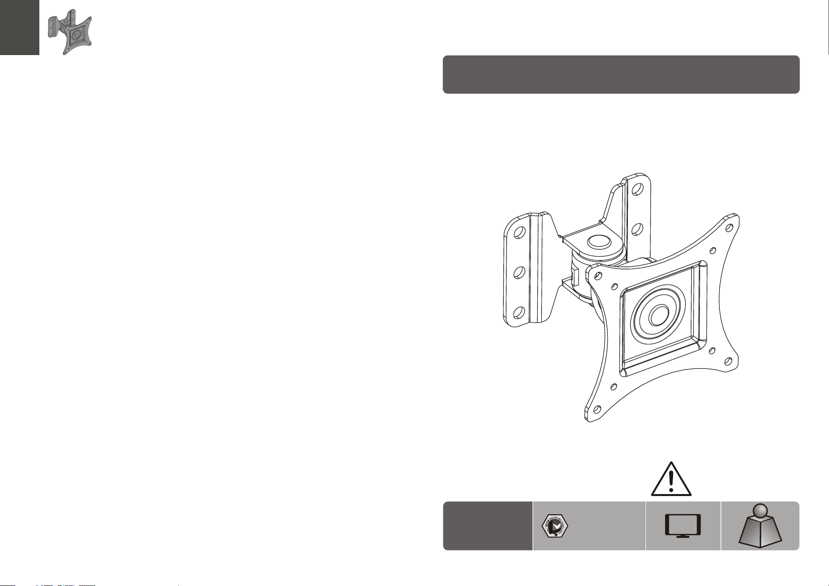
LCD Wall Mount
LC D-30 2
75x75 /10 0x1 00
CA UT ION: DO N OT EXCEED
RATE D LIS TED WE IGH T. SERI OUS
INJ URY OR P ROP ERTY DAMA GE
MAY OCCUR!
27"
MAX
(33lbs)
(33lbs)
RATE D
RATE D
ISSUED: FEB. 2013
15kg
15kg
Page 2
NOTE: Rea d the entire instr uction manual be fore you st art ins tallati on and assembly.
WARNING
• Do not begin the installation until you have read and understood all the instructions
and warnings contained in this installation sheet. If you have any questions
regarding any of the instructions or warnings, please contact your local distributor.
• This mounting bracket was designed to be installed and utilised ONLY as
specified in this manual. Improper installation of this product may cause damage
or serious injury.
• This product should only be installed by someone with good mechanical ability
who has basic building experience and fully understands this manual.
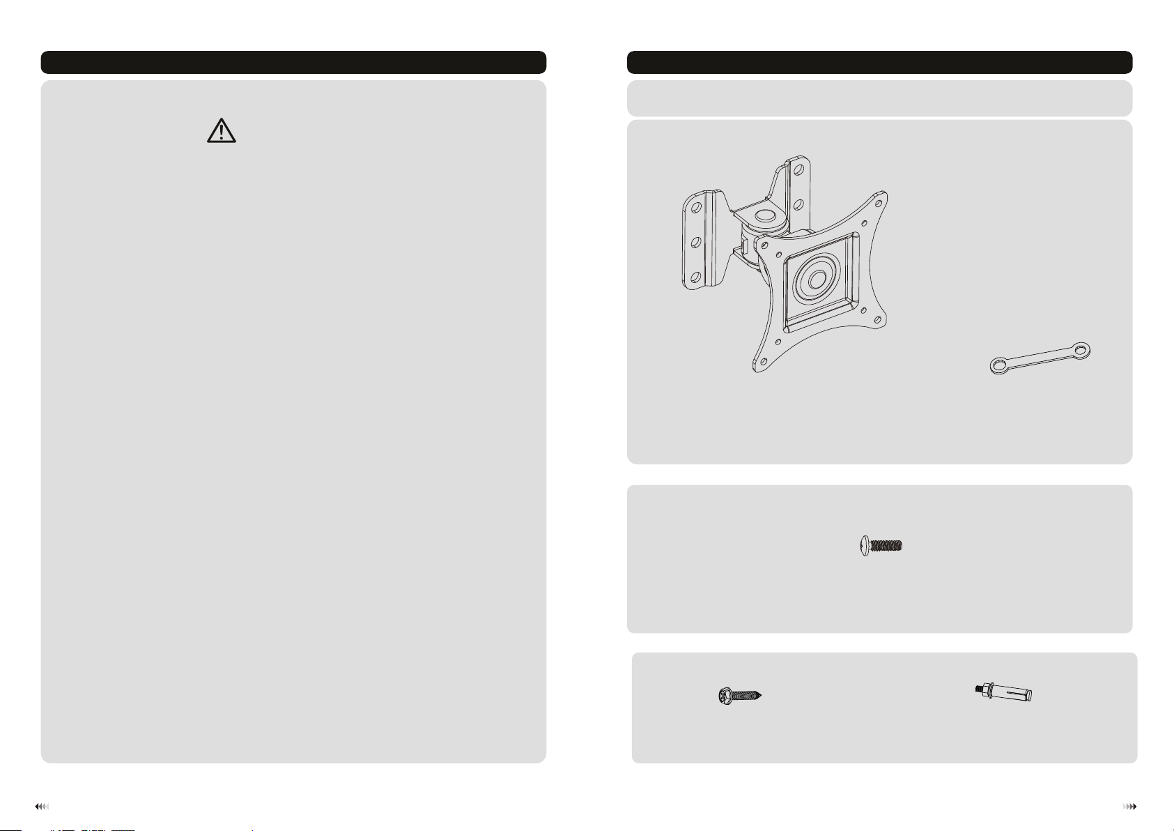
Component Checklist
IMPORTANT: Ensure t hat y ou ha ve re ceived al l par ts ac cor ding to the c omp one nt ch eck list prio r to in sta lla tion.
If an y par ts ar e mis sing or fau lty, t ele phone you r loc al di str ibutor fo r a rep lac eme nt.
• Make sure that the supporting surface will safely support the combined weight of
the equipment and all attached hardware and components.
• If mounting to wood wall studs, make sure that mounting screws are anchored
into the center of the studs. The use of a stud finder is highly recommended.
• Always use an assistant or mechanical lifting equipment to safely lift and position
the equipment.
• Tighten screws firmly, but do not over tighten. Over tightening can cause damage
to the items, This greatly reduces their holding power.
• This product is intended for indoor use only. Using this product outdoors could
lead to product failure and personal injury.
Package M
Package W
wall mount (x1)
M6 x30 ( x2)
W-A
wrench (x1)
A
M4x14 ( x4)
M-A
iron expansion bolt (x2)
W-B
B
21
Page 3

1a. For Wood Stud Wall Mounting
55mm
55mm
30mm
(2.2")
2.2"( )
(1.2")
ø 4.5mm
(ø 3/16")
1b. For Solid Brick and Concrete Mounting
60mm
60mm
60mm
2.4"( )
(2.4")
(2.4")
ø 10mm
(ø 3/8")
XX
W-A
1
Find an d mar k the e xac t
locat ion o f mou nti ng ho les
√
2
3
Drill pilot holes
X X
Screw the wall
mount onto
the wall
W-B
√
1
Mark th e exa ct
locat ion o f
mount ing h ole s
2
Drill pilot holes
X X
Screw the wall
mount onto
the wall
WARNING
• Make sure that mounting screws are anchored into the center of the studs. The use of a stud
finder is highly recommended.
• Installers are responsible to provide hardware for other types of mounting situations.
• Installers must verify that the supporting surface will safely support the combined weight of the
equipment and all attached hardware and components.
3
WARNING
Installers must verify that the supporting surface will safely support the combined weight of
the equipment and all attached hardware and components.
4
Page 4

2. Attaching the Display to the VESA Plate
3. Adjustment
TV
TVTV
B
Tension is pre-set at the factory. If too tight or too
loose, you may adjust the tensi on by loosen ing or
tightening the head and arm adj ustment bolts.
+45°
M
-A
18 0°
±180°
Lift th e dis pla y and m atch the holes on y our d isp lay w ith the holes on th e mou nt. S ecu re your display t o
the mou nt by t igh ten ing screws.
Tig hten all screws b ut do n ot ov er ti ghten.
-45°
Adjus t to th e des ire d position or til t.
Maint ena nce
• Check t hat t he br ack et is secure and sa fe to u se at r egu lar intervals (at l eas t eve ry three months ).
• Pleas e con tac t you r dealer if you hav e any q ues tio ns.
65
 Loading...