

Page 1
Driving Visual Innovation
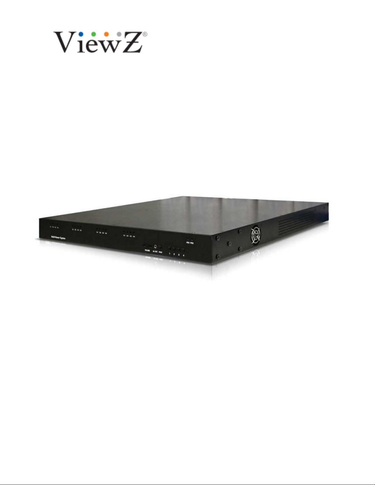
VZ-MV802
MULTIVIEWER SYSTEM
VERSION 1.0
Dated Dec. 21, 2018
All contents of this document may change without prior notice, and actual product appearance may differ from that depicted
herein
HARDWARE MANUAL
Page 2

TABLE OF CONTENTS
COMPLIANCE INFORMATION....................................................................................................3
WARRANTY STATEMENT ..........................................................................................................3
Limitation of Liability.................................................................................................................4
Extended Warranty Options.....................................................................................................5
Services and Repairs outside the Warranty Period..................................................................5
Disclaimer.................................................................................................................................5
Operating Environment ............................................................................................................5
INTRODUCTION TO VZ-MV802 MULTIVIEWERS.......................................................................6
HARDWARE.................................................................................................................................6
VZ-MV802 PLATFORM PRODUCT LINE.....................................................................................6
TECHNICAL SPECIFICATIONS ..................................................................................................8
PHYSICAL SPECIFICATIONS...................................................................................................13
INSTALLATION..........................................................................................................................16
OPERATION...............................................................................................................................18
APPENDIX A: CONNECTORS ..................................................................................................20
APPENDIX B: REDUNDANT POWER SUPPLIES....................................................................26
CONTACT VIEWZ.....................................................................................................................28
Page 3

COMPLIANCE INFORMATION
The ViewZ equipment has been tested to comply with the following.
• FCC - Class A
This equipment has been tested and found to comply with the limits for a Class A digital
device, pursuant to part 15 of the FCC Rules. These limits are designed to provide
reasonable protection against harmful interference when the equip ment is operated in a
commercial environment. This equipment generates, uses, and can radiate radi o
frequency energy and, if not installed and used in accordance with the instruction
manual, may cause harmful interference to radio communications. Operation of this
equipment in a residential area is likely to cause harmful interference in which case the
user will be required to correct the interference at his / her own expense.
• CE
• C-Tick
• RoHS
WARRANTY STATEMENT
ViewZ warrants to the original purchaser of the products manufactured by ViewZ (the “Product,”) will be
free from defects in material and workmanship for a period of three (3) year from the date of shipment
of the Product to the purchaser.
If the Product proves to be defective during the three (3) year warranty period, the purchaser’s
exclusive remedy and ViewZ’s sole obligation under this warranty is expressly limited, at ViewZ’s sole
option, to:
(a) repair the defective Product without charge for parts and labor or
(b) provide a replacement in exchange for the defective Product or
(c) if after a reasonable time, is unable to correct the defect or provide a replacement
Product in good working order
then the purchaser shall be entitled to recover damages subject to the limitation of liability set forth
below.
3
Page 4

BLimitation of Liability
ViewZ’s liability under this warranty shall not exceed the purchase price paid for the defective product.
In no event shall ViewZ be liable for any incidental, special or consequential damages, including without
limitation, loss of profits for any breach of this warranty.
If ViewZ replaces the defective Product with a replacement Product as provided under the terms of this
Warranty, in no event will the term of the warranty on the replacement Product exceed the number of
months remaining on the warranty covering the defective Product.
Equipment manufactured by other suppliers and supplied by ViewZ carries the respective manufacturer’s
warranty. ViewZ assumes no warranty responsibility either expressed or implied for equipment
manufactured by others and supplied by ViewZ.
This hardware warranty shall not apply to any defect, failure or damage:
a) Caused by improper use of the Product or inadequate maintenance and care of the
Product;
b) Resulting from attempts by those other than ViewZ representatives to install, repair, or
service the Product;
c) Caused by installation of the Product in a hostile operating environment or connection of the
Product to incompatible equipment; or
d) Caused by the modification of the Product or integration with other products when the effect of
such modification or integration increases the time or difficulties of servicing the Product. Any
Product which fails under conditions other than those specifically covered by the Hardware
Warranty, will be repaired at the price of parts and labor in effect at the time of repair. Such
repairs are warranted for a period of ninety (90) days from date of reshipment to customer.
4
Page 5

2Extended Warranty Options
ViewZ offers OPTIONAL Extended Warranty plans that provide continuous coverage for the Product
after the expiration of the Warranty Period. Please contact an ViewZ sales representative for details
on the options that are available for your ViewZ equipment.
2
Services and Repairs outside the Warranty Period
ViewZ makes its best offer to repair products that are outside the warranty period, provided the
product has not reached its end of life.
B
Disclaimer
Use of this product is limited to the intended design purpose. Any damage caused by use other than the
design purpose will void the above warranty.
2Operating Environment
ViewZ VZ-MV802 Multiviewers should be operated in an environment that is safe for sensitive
electronic equipment. It should not be placed in hot, dusty, or humid locations without
adequate cooling, filtration, or ventilation.
5
Page 6

INTRODUCTION TO VZ-MV802 MULTIVIEWERS
The ViewZ VZ-MV802 Multiviewer platform displays multiple auto-detecting video inputs at different
formats on a high resolution display up to resolutions of 2048x1080. The VZ-MV802 Platform
combines the display of video windows, audio meters, label/UMD, tallies, alarms and indicators in a
very space efficient package.
HARDWARE
The ViewZ VZ-MVxxx Multiviewer Platform consists of 2 different sizes of mechanical frames to serve
the needs of broadcast, professional AV and surveillance markets. Each multiviewer frame has a
unique IP address, which allows a PC/laptop to easily connect and configure the display layouts.
6
Page 7
VZ-MVxxx PLATFORM PRODUCT LINE
Two types of mechanical frames are available for the VZ-MVxxx family:
1. VZ-MV802: The 1 RU VZ-MV802 accepts 8 video inputs including from HDMI*, DVI or VGA.
The VZ-MV802 has two flexible DVI/HDMI (1.2/1.3) with user selectable resolutions up to
2048x1080. Analog or AES audio options can be added at any time during or after the
purchase.
*Flexible Outputs – VZ-MV802 examples:
Output(s)
1 2
Inputs 4 4
Inputs
2. VZ-MV1604: The 2 RU VZ-MV1604 accepts 16 video inputs including HDMI*, DVI or VGA.
The VZ-MV1604 has four flexible DVI/HDMI (1.2/1.3) with user selectable resolutions up to
2048x1080. Analog or AES audio
purchase.
*Flexible Outputs –VZ-MV1604 examples:
Inputs
Inputs
Inputs 8
Inputs 12 4
Inputs 16
options can be added at any time during or after the
Output(s)
1 2 3 4
4 4 4 4
4 4
8
8
8
*OPTIONS
*OPTIONS
7
Page 8

TECHNICAL SPECIFICATIONS
• Auto detect HD-SD/SDI/CV 50/60Hz (available formats depends on the model)
• Auto detect HDMI/DVI/VGA/CV/YC/component (available formats depends on the model)
• Output resolution up to 2048x1080 (720x480 – 2048x1080)
• Digital and Analog clocks can be synchronized with NTP or LTC (time code)
• Up to 30 presets for display layout
• Presets can be recalled via GPI, front panel buttons or ASCII protocol via network or serial
• On Screen Display (OSD) for labels, border and alarms can be customizable via iSkin® with
industry standard graphical tools
• Auto-detect aspect ratio between 16x9 and 4x3
• Communication interface via IP or RS232
• Supports ViewZ eXtended Protocol (AXP)
• Supports direct TSL tally/UMD interface
• Supports multiple languages (including 2 byte characters)
• Supports SDI output (optional)
8
Page 9
Table 1: Serial Video input (OPTION)
Standards
Connector
Equalization
Return Loss
Embedded Audio
Upgradeable to 3Gb/s (SMPTE
424M) HD-SDI (SMPTE 292M) SDSDI (SMPTE 259M-C) PAL/NTSC
BNC
Automatic to 140m (Belden 1694A)
15db up to 270mb/s
SMPTE 272-A
Table 2: Video Formats supported
480i 720p/30 1080p/23.98 2048x1080p/23.98
480p 720p/50 1080p/24 2048x1080p/24
576i
576p 720p/60 1080p/29.97
720p/23.98 1035i/59.94 1080p/30
720p/24 1035i/60 1080sf/23.98
720p/25 1080i/50 1080sf/24
720p/29.97
720p/59.94 1080p/25
1080i/59.
94 1080sf/30
Table 3: Computer Formats supported (50/ 60Hz)
720x480 852x480 1024x768 1280x768
800x600 1280x960 1280x1024 1360x768
1280x800 1400x900 1400x1050 1600x1200
1366x768 1920x1080 1920x1200 1680x1050
Table 4: Audio input
Type Default Option
AES 75 Q unbalanced via BNC 110 Q balanced via XLR
Analog Stereo
Unbalanced via BNC balanced via XLR
9
Page 10

Table 5: Display Output
Standards
Connector
Impedance
HDMI 1.3 up to 2048x1080, SDI*
HDMI
100Q, 75Q
*OPTION
Table 6: Audio Outputs
Type Number/type/connector Location Adjustment
AES 1 / unbalanced / BNC Rear Panel None, Line Level
Stereo Analog 1 / unbalanced / phone jack Rear Panel None, Line Lev el
Stereo Analog 1 / unbalanced / phone jack
Front Panel Front Panel knob
Table 7: Output Resolution (50 and 60Hz)
720x480 852x480 1024x768 1280x768
800x600 1280x960 1280x1024 1360x768
1280x800 1400x1050 1600x1200 1680x1050
1366x768 1920x1080 1920x1200 2048x1080
TabLE-8: General Purpose Interface I/ O
Number On VPM On CPM
Inputs
Outputs
Connector
8, assignable to input or
output
8, assignable to input or
output
DB9 RJ50 to DB9
8, assignable to input or
output
8, assignable to input or
output
10
Page 11

Figure 1: GPI/O Electrical Characteristics
Table 9: Serial Port
Number of Ports 1 x RS232
Adapter RS232 to RS422 or RS485 (optional)
Connector RJ45
Baud Rate
UMD support
Up to 115200
Native to TSL and TSI, other third party
protocols
Table 10: Ethernet
Network Type
Connector
Cable
UMD support
*UIM – Universal Interface Module. The UIM is a small footprint router protocol translator that acts s a
bridge between the VZ-MV802 platform of multiviewers and other third party router, tally and UMD
protocols. The UIM can support third-party TCP/IP, UDP as well as serial protocols. The UIM can also act
as an SNMP agent for the ViewZ VZ-MV802 multiviewers.
Fast Ethernet 100 Base-TX
RJ45
Auto-detect. Either straight or crossed cable will
work
Native to TSL and TSI, other third party
protocols
11
Page 12

Table 11: Timecode
Timecode LTC
Connector BNC
12
Page 13

Physical Specifications
Size
Rack installation
Weight 12 lbs. (2.8kg)
Power
Noise Level
Figure 2 - 3 shows the front and back panels of the VZ-M802
H: 1.75 in (4.45 cm, 1RU)), W: 18 in (21.6
cm), D: 13 in (33 cm)
Standard 19-inch equipment rack.
90/250 VAC, 60/50Hz, 100 W, internal auto
switchable
Maximum 38dB. VZ-MV802 has temperature
sensor to regulate fan speed, actual noise
may be much lower
level
Figure 2: VZ-MV802 front panel view
Front Panel indicators, connectors and buttons are:
1. Signal presence LED
2. Power supply status
3. Audio volume adjustment
4. Audio phone jack output
5. Paging mode
6. Buttons to recall presets
13
Page 14

Figure 3: VZ-MV802 rear panel view
Rear Panel indicators, connectors and buttons are:
1. For HDMI output up to 2048x1080 @30ft (10 meters).
2. DVI-I’s: Input for video (auto-detect HDMI (with adapter), DVI, VGA (with adapter).
3. BNC’s: HD/SD-SDI, and 3G HD-SDI (option)
4. BNC: LTC input to sync on screen clocks
5. BNC: Line level AES audio monitor output*
6. Rotary Switch: Reserved for future use
7. RJ50: GPI/O for control, alarm and tally
8. RJ45: RS232 serial
9. RJ45: IP control
10. SCSI connector: for discrete audio and GPI/O
11. Phone Jack: Line level stereo audio monitor output*
12. Redundant DC Power 12V
13. AC Power – 90 to 250 50/60Hz
*Audio monitoring is available in line level in stereo and AES
14
Page 15

What’s in the box
Accessories / Models
1 Hardware 1
Power Cord
2
(North America Only)
3 VGA to DVI-I Adaptor 8
RJ-50-DVI Adapter
4
RJ-50HDMI
5
DC Redundant Power Supply
6 I/O 2
7
SCSI-DB9 GPI/Audio Cable
RJ45-DB9 RS232 Cable
RJ50-DB9 GPI I/O Cable
8 CD - VZ Commander, User Manual 1
VZ-MV802
1
2
1
1
2
1
1
15
Page 16

INSTALLATION
Mechanical Installation:
VZ-MV802 can be installed in a standard 19” rack using the proper screws and washers (not
included). VZ-MV802 modules are shipped with rack ear. These accessories are not installed to
ensure proper shipment. First locate them in the accessories box and then install them.
Note: For proper ventilation, make sure the side panel air vents are not blocked.
Figure 4: Rack mount and airflow for VZ-MV802 frames
16
Page 17

Power Connection:
Connect the AC power cord to the rear panel AC receptacle-. The VZ-MV802 - includes
a Universal power supply for 90V to 250V operation, and DC redundant power supply
17
Page 18

OPERATION
UPowering Up
There is no power switch on the VZ-MV802 Multiviewer. Plugging in the power cord will turn on
the Multiviewer. Unplugging the power cord will turn off the Multiviewer.
U
Connection / Indicator / Button Descriptions
• 8 DVI-I connectors for auto-detect high resolution inputs
• 16 embedded audio meters per SDI inputs
• 8 GPI/O on the control board for alarms and recalling presets
• 8 GPI/O on the video processing board for tally, alarm and recalling presets
• 1 Ethernet connection for control and configuration
• 1 RJ45 input for serial connection
• 1 BNC for AES audio output for monitoring
• 1 phone jack on the rear panel for line Level analog audio monitoring
• 1 phone jack on the front panel with volume control for audio monitoring
• 1 BNC for LTC input
• 2 HDMI(1.2/1.3) outputs
• Temperature sensor to control fan speed
• LED for input status (present/absent). One LED per input
• 5 buttons on the front panel to recall presets
18
Page 19

Optional Hardware
• Unbalanced Analog audio inputs (16 inputs per video processing card)
• Unbalanced AES audio inputs(8 inputs per video processing card)
• Balanced Analog audio inputs (16 inputs per video processing card)
• Balanced AES audio inputs(8 inputs per video processing card)
• RJ45 to VGA Receive
Figure 5: VZ-MV1604 setup with a single output (16 windows), displaying
analog and digital clocks with standalone labels and audio meters
19
Page 20

APPENDIX A: CONNECTORS
UBNC Inputs:
•
4 X BNC Connector (option)
• Auto Detection for SDI and CVBS signal
Figure 6: 75 o
• SCSI Connector for Audio and GPI/O
• 8 GPIO
• 8 AES
• 16 Analog audio
• Others are Grounds
• TOTAL 68 PINS
hm BNC Connector
20
Page 21

Figure 6: 68 pin SCSI Connector
Pin # 17 18 35 36 37 38 39 40 41 42
Function
AA
AES#4
#12
43 44 45 46 47 48 51 52 53 55 56
AA #05
AA
#09
AA
#06
57 58 59 60 61 62 63 64 65 66 67
AES #2
AES
#7
MOD
E A
68
GPIO
#3
U
AA
#08
AA
#16
MOD
E B
AA
#07
AA
#10
GPIO
#08
AA
#03
AA
#15
GPIO
#07
AA
#04
AES
#5
GPIO
#06
AA
#02
AES
#11
GPIO
#05
AA
#14
AES
#1
GPIO
#02
AA
#01
AES
#06
GPIO
#04
AA
#13
AES
#03
GPIO
#1
21
Page 22

HDMI Output Connector:
HDMI Input Connector
Pin # 1 2 3 4 5 6 7 8
Function Clk+ Clk- Data 2+ Data 1- Data 1+ Data 2- Data 0+ Data 0-
U
22
Page 23

RS232 RJ45 Connector:
•
1 pin for Tx
• 1 pin for Rx
• 3 pins for 5V power
• 3 pins for GND
P
in #
Function 5V GND Tx GND Rx GND 5v 5v
U GPI I/O:
RJ-50 defined GPI I/O
•
1 2 3 4 5 6 7 8
• 8 pins GPI I/O
• 1 power alarm
• 1 GND
Pin # 1 2 3 4 5 6 7 8 9 10
Function
GPI
I/O
#1
GPI
I/O
#2
GPI
I/O
#3
GP
I
I/O
GPI
I/O
#5
GPI
I/O
#6
GP
I
I/O
GP
I
I/O
Power
Alarm
GND
Figure 8: RJ50 to DB9 cable
23
Page 24

Figure 9: GPI-IN Wiring diagram. Connect this terminal block
to the RJ50 to DB9 cable shown in Figure 10.
24
Page 25

Figure 10: GPI-OUT Wiring diagram. Connect this terminal block
to the RJ50 to DB9 cable shown in Figure 10. Note: All LED are
standard LED’s, all resistors are 150 ohms
25
Page 26

APPENDIX B: REDUNDANT POWER SUPPLIES
• Input: Universal 100-240 VAC / 47-63 HZ input, without any slide switcher output: 12V / 0~5A
• Case Dimension: 120L X 60W X 38 H MM
• Efficiency: 78% is typical
• Safety: UL/CUL/GS/PSE/BSMI
• EMI: FCC/CE Class B, conduction and radiation has been met.
• High frequency design, less power consumption
• CEC law (energy efficiency) has been met
• Over voltage protection, short circuit protection
UInput:
Voltage
Frequency
Current 1.5A Max
Inrush Current 30A Max/100VAC; 60A Max / 240VAC
Efficiency 78% minimum 9At normal line voltage, full Load)
UDC Output:
Voltage 12.00V
Current
Regulation Vo+-5%
Ripple- and Noise 200 mV Max
Total Power 60 W Max
Protection:
U
Range: Universal 100-200 VAC, single- phase
Nominal: 100–120 VAC / 200-24-VAC
47 – 63Hz
5A MAX
Over Voltage Protection V out (110% - 140%)
Short Circuit Protection
Automatic recovery after short circuit fault
removed
26
Page 27

Operational & Environmental Performance:
Temperature Range
Operating
Storage ~ 20 OC~C +60 OC
Humidity Range (non-condensing)
Operating OPERATING 20%~ 80% RH
Storage STORAGE 10% ~ 9 0 % RH
Cooling should operate without fan
MTBF: 50000 HOURS Min: 25OC FULL LOAD
MECHANICAL
WEIGHT: 320g
CABLX- TYPE UL 1185 18AWG
WIRE + PLUG
BLACK
PLUG: 5.5 X
2.5 X 10 mm
0 OC~C +40 OC
Lock Ring to secure
connection
CABLX- LX-NGTH: 150 cm
CASE DIMENSION: 120 mm(L) x 60mm(W) x 38mm(H)
EXTERNAL LOOK:
MATERIAL FLAMMABILITY: UL 94V-0
27
Page 28

CONTACT VIEWZ.
For troubleshooting, support and service, as well as upgrades, please
contact:
Phone: +1 714 996 1177
Email: rma@viewzusa.com
ViewZ
177 W. Orangethorpe Av
Placentia, CA 92870 USA
Phone: +1 714 996 1177
Fax: +1 714 996 1138
Email:rma@viewzusa.com
URL : www.viewzusa.com
e,
28
 Loading...