

Page 1
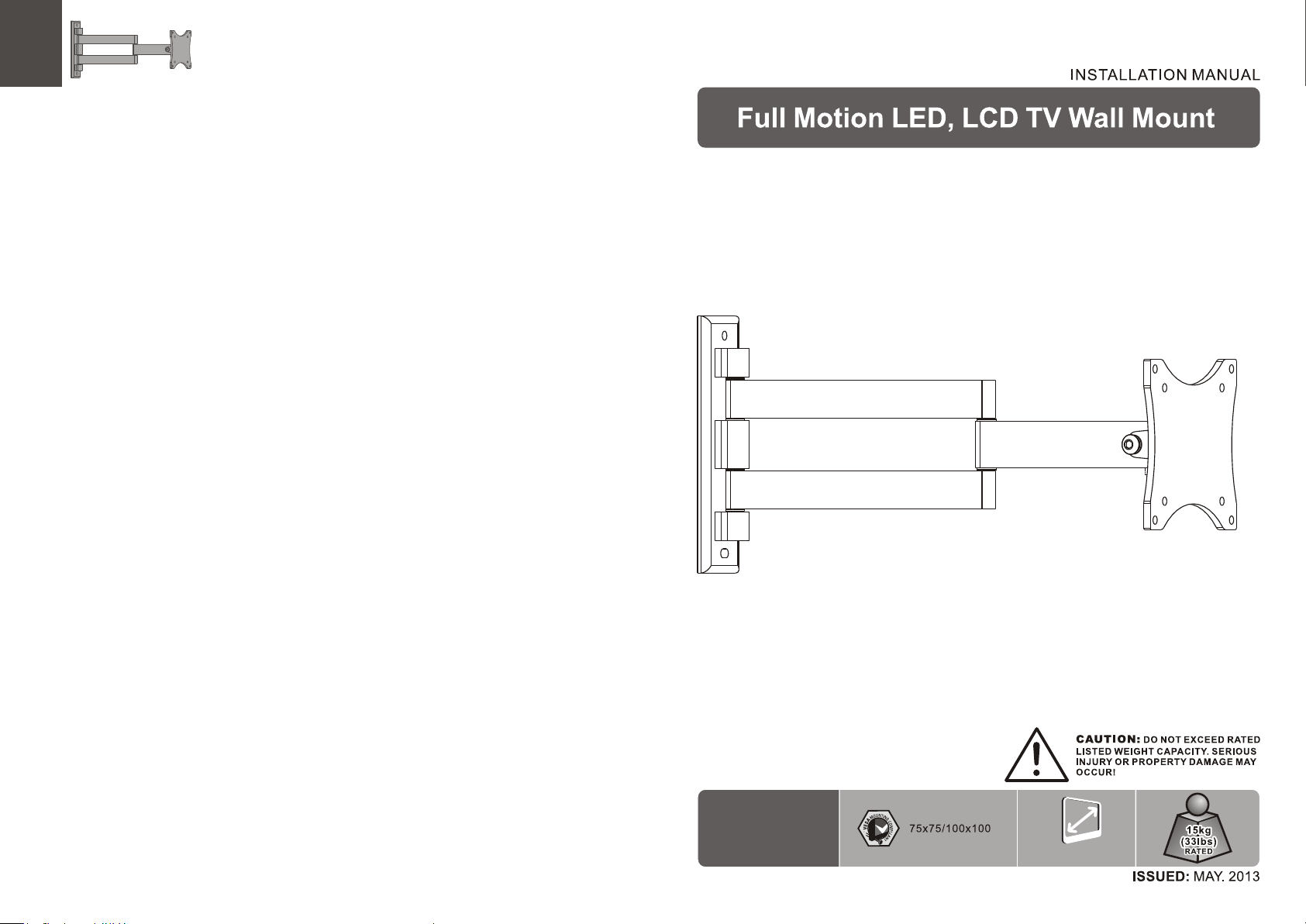
VZ-AM01
Display 10”~24”
Page 2
NOTE: Read the entire instruction manual before you start installation and assembly.
WARNING
• Do not begin the installation until you have read and understood the instructions
and warnings contained in this installation sheet. If you have any question
regarding any of the instructions or warnings, please contact your local distributor.
• This mounting bracket was designed to be installed and utilised ONLY as
specified in this manual. Improper installation of this product may cause damage
or serious injury.
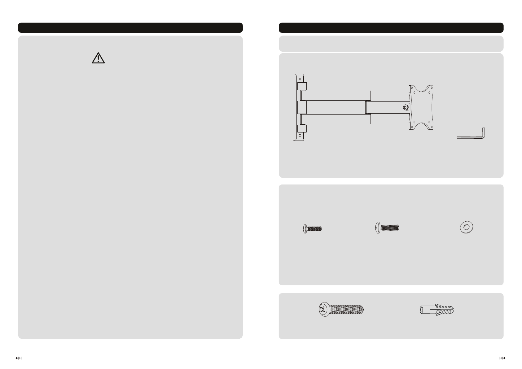
Component Checklist
IMPORTANT: Ens ure t ha t you h ave r ec eiv ed al l pa rts a cco rd ing t o the c om pon ent c he ckl ist p ri or to i nst al lat ion .
If an y pa rts a re mi ss ing o r fau lt y, tel eph one y ou r loc al di st rib uto r fo r a rep lac em ent .
• This product should only be installed by someone with good mechanical ability
who has basic building experience and fully understands this manual.
• Make sure that the supporting surface will safely support the combined weight of
the equipment and all attached hardware and components.
• If mounting to wood wall studs, make sure that mounting screws are anchored
into the center of the studs. The use of a stud finder is highly recommended.
• Always use an assistant or mechanical lifting equipment to safely lift and position
the equipment.
• Tighten screws firmly, but do not over tighten. Over tightening can cause damage
to the items, This greatly reduces their holding power.
• This product is intended for indoor use only. Using this product outdoors could
lead to product failure and personal injury.
Package M
M4x14 ( x4 )
Package W
wall mount (x1)
A
M-A
ST5.5 x5 0 (x2)
W-A
M5x14 ( x4 )
M-B
D5 wash er ( x4)
concr et e ancho r (x2)
W-B
Allen key (x1)
B
M-C
21
Page 3

1a. Wood Stud Wall Mounting
50mm
50mm
50mm
(2")
2"( )
(2")
ø 4mm
(ø 5/32”)
1b. Solid Brick and Concrete Mounting
55mm
55mm
2.2"( )
(2.2")
ø 8mm
(ø 5/16")
W-A
1
2
Find an d ma rk the
exact l oc ation o f
mount in g holes
3
Drill pilot holes
√
X X
Screw the wall
mount onto the
wall
W-B
W-A
1
Mark th e
exact l oc ation o f
mount in g holes
2
Drill pilot holes
√
X X
Screw the wall
mount onto the
wall
WARNING
• Make sure that mounting screws are anchored into the center of the studs. The use of a stud
finder is highly recommended.
• Installers are responsible to provide hardware for other types of mounting situations.
• Installers must verify that the supporting surface will safely support the combined weight of the
equipment and all attached hardware and components.
3
WARNING
Installers must verify that the supporting surface will safely support the combined weight of the
equipment an d all attached hardw are and components.
4
Page 4

2. Attach the Display to the VESA Plate
M-C
M-A/M -B
Lift th e di splay a nd matc h th e holes o n yo ur disp lay wit h th e holes o n the mou nt . Secur e your di sp lay to
the mou nt b y tight ening s cr ews.
Tig ht en all sc rews bu t do n ot over t ig hten.
3. Adjustment
18 0° 18 0° 18 0°
Adjust to the desired location or til t.
B
Tension is pre-set at the factory. If too tight or too
loose, you may adjust the tension by loosening or
tightenin g the head and ar m adjust ment bolts.
+70 °
-70 °
B
Tighten the adjustment screw by using an Allen Key provided to fix the tilting angle.
Maint en ance
• Check t ha t the bra cket is s ec ure and s afe to use at r egula r in terva ls(at l ea st ever y three m on ths).
• Pleas e co ntact y our dea le r if you ha ve a ny ques tions .
65
 Loading...