

Page 1

ViewZ 5.6" HD-SDI CCTV TEST MONITOR
5.6" HD-SDI CCTV TEST MONITOR
User ’s Manual
Please read this Manual carefully before use of this product, and keep it handy for future reference.
Page 2

ViewZ 5.6" HD-SDI CCTV TEST MONITOR
Page 3

1
ViewZ 5.6" HD-SDI CCTV TEST MONITOR
I. Packing List ……………………………………………….. 2
II. Product Appearance………………………………………... 3-5
III. Product Operation………………………………………….. 6-8
IV. Screen Display……………………………………………... 9-10
Contents
V. List of Supported Display Modes………………………….. 11
VI. Technical Parameters………………………………………. 12
VII. Troubleshooting………………………………………….13-14
Page 4
2
ViewZ 5.6" HD-SDI CCTV TEST MONITOR
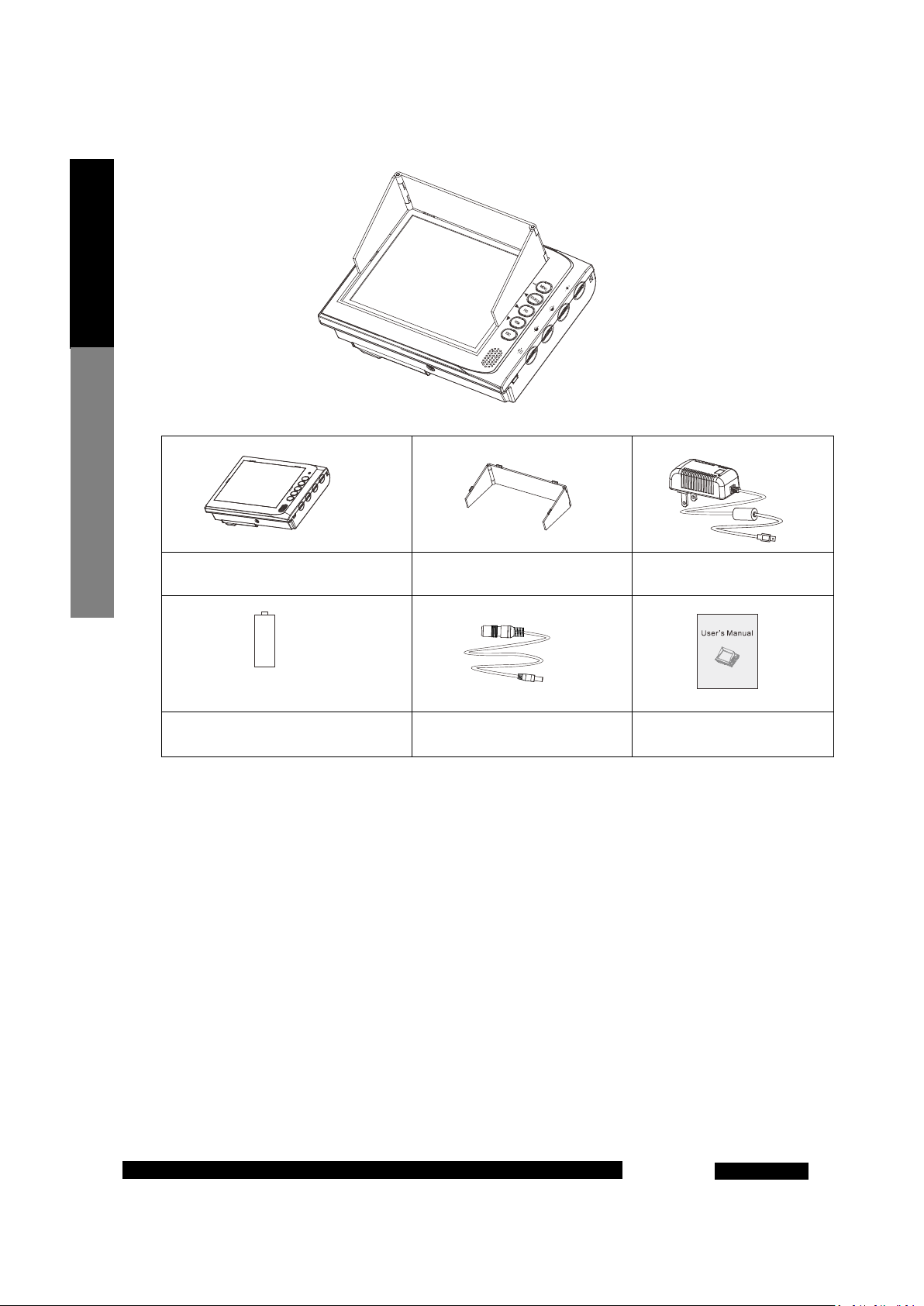
Packing List
5.6" multifunction monitor × 1 pc
Ni-MH battery × 4 cells 12V power output cable ×1pc User’s Manual × 1 copy
Sun visor × 1 pc Power adapter × 1pc
Page 5
3
ViewZ 5.6" HD-SDI CCTV TEST MONITOR
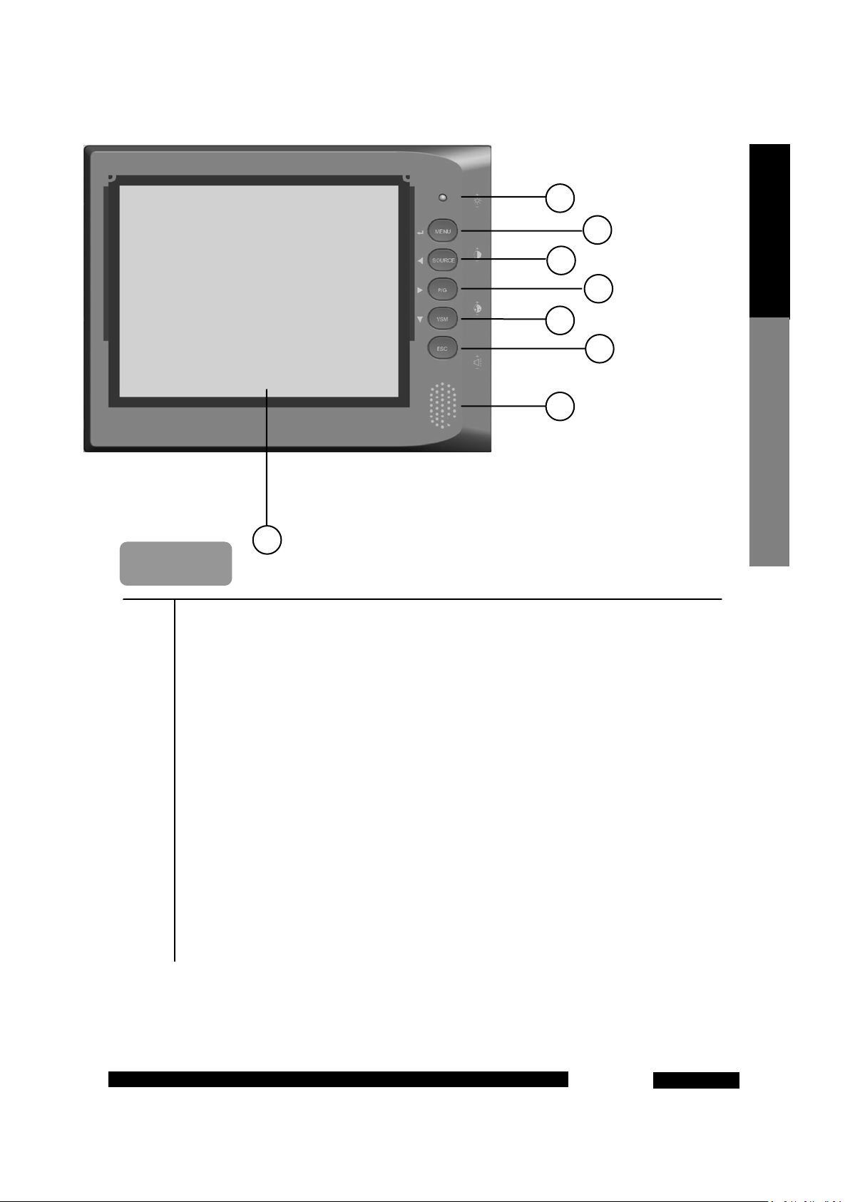
Front View
Product Appe arance
1 5.6 " LCD panel (adopting tempered glass cover).
2 LED indicator.
3 MEMU Key: The main menu key, acting as the Enter Key during menu operation.
4 SOURCE Key: With the function of signal channel switching, acting as the Left Selection Key
during menu operation.
5 P/G Key: With the function of color bar signal output built in this device, acting as the Right
Selection Key during menu operation.
6 VSM Key: With the function of display of signal intensity and other information, acting as the
Down Selection Key during menu operation.
7 ESC Key: exit and return to previous menu.
8 Speaker
Page 6

Rear V iew
Left Side View
4
ViewZ 5.6" HD-SDI CCTV TEST MONITOR
Product Appearance
1 Video 2 signal input interface or SDI signal input interface (depending on the
product model).
2 Audio signal input interface.
3 Video signal output and color bar signal output interface
4 DC12V --350MA output interface.
5 Power switch. The product can work properly only when the switch is turned “ON”.
6 VGA signal input interface.
7 HDMI signal input interface.
Page 7

Right Side View
Top V iew
5
ViewZ 5.6" HD-SDI CCTV TEST MONITOR
Product Appe arance
1 Picture brightness adjusting knob: turn it upwards to increase the brightness, and turn
it downwards to decrease the brightness.
2 Picture contrast adjusting knob: turn it upwards to increase the contrast, and turn it
downwards to decrease the contrast.
3 Picture saturation adjusting knob: turn it upwards to increase the saturation, and turn
it downwards to decrease the saturation.
4 Volume adjusting knob: turn it upwards to increase the volume, and turn it downwards
to decrease the volume.
5 DC12V-1500MA power input interface.
6 Video 1 signal input interface.
Page 8

of each battery; installation with
electrical failures and damage the
display effects to meet
6
ViewZ 5.6" HD-SDI CCTV TEST MONITOR
Product Operation
Step 1: As shown in Fig. 1, put four
Ni-MH cells in the battery compartment
of the product in sequence according to
the anode and cathode marks. (Please
pay attention to the anode and cathode
reversed node and cathode may result in
Step 2: Turn the power switch “ON”, the
LED indicator stays on in green and the
device is working properly.
Step 3: According to the current signal
access mode, press “SOURCE” on the right
side of panel to select the corresponding
signal channel.
Step 4: Use the keys on the front panel
and the knobs on the right side to adjust
the picture
individual needs.
Page 9

Charge and Discharge
Battery Test
DC12V output
Other Precautions
7
ViewZ 5.6" HD-SDI CCTV TEST MONITOR
Connect the DC12V-1500mA charger
from the accessories according to the
figure shown, and connect to the AC
pow e r.
Product Operation
After the charger is inserted, the LED indicator (green-green-off) acts once; then, it enters the test state,
and the LED indicator flashes fast (red-green-red-green…) for about 13 times; if the battery has no defects,
it will enter the normal charging state.
► State of the LED indicator when the battery level is lower than 50%: red-green-off- red-green-off…
► State of the LED indicator when the battery level is higher than 50%: red-green-red-green-red-green…
► State of the LED indicator when the battery level is 100% (fully charged): constantly green.
► If the charger is inserted again after the battery is fully charged, it will continue to charge for about 30min before stop.
★Note: When the battery is fully charged, please do not repeatedly charge it for several successive times if it is in use; or else,
the battery may be damaged. Please charge the battery when its level is below 10% or when the device can not be turned on
completely; due to the memorability of Ni-MH battery, repeated abnormal charging may shorten the service life of the battery.
► The product is designed with complete circuit protection; when the DC12V output interface has no load access, the DC12V
output voltage is approximate to the current battery voltage and the output current is about 0.5mA. When normal load is accessed,
the circuit will automatically open DC12V output; after load disconnection, DC12V output will not be closed; it is needed to restart
the device to restore output protection.
► When the battery voltage is ≥4.3V, the maximum load of DC12V output is 350mA.
► Over-current and short circuit both can enable the circuit protection, thus to automatically cut off DC12V output. During
protection, the circuit will automatically repeatedly test whether the load is normal at a time interval of 2-3s; when the load returns
to normal, DC12V output will also automatically return to normal.
► This product is designed with the overheating protection function during charging and discharging of the battery; it is set that
the circuit protection will be enabled when the internal temperature of the product is over 62℃, at which moment it is not allowed
to charge the battery or turn on/off the device. The protection cannot be removed by replacing the battery with a new one; it can
be removed only when the temperature of the temperature sensing component on the circuit board returns to normal.
► This product is designed with the battery over-discharge protection function; it is set that the circuit protection will be
enabled when the working current of the product exceeds 2600mA, at which moment the device cannot be turned on to work
properly; the protection can be removed only by restarting the device.
► This product is designed with the battery over-voltage protection function; it is set that the circuit protection will be enabled
when the battery voltage of the product exceeds DC6.5V, at which moment the device cannot be powered on automatically even
when the battery voltage returns to 4.8V; the protection can be removed by turning it off again.
When the battery is charged normally
Page 10

8
ViewZ 5.6" HD-SDI CCTV TEST MONITOR
Product Operation
Information Display on the Screen
1 Battery charging icon.
2 Display of the signal channel information and resolution of the current screen.
3 Display of battery level and indication of DC12V output state.
4 Display of the intensity of the current video signal input.
Page 11

Main Menu (Picture)
to select
olor temperature: Four modes are optional,
Noise Reduction: Four modes are optional,
, and
the real one, depending on the product
the real one due to product upgrading.
9
ViewZ 5.6" HD-SDI CCTV TEST MONITOR
This interface may be slightly different from
This interface may be slightly different from
Signal Selection Menu
Operation method: Press the “SOURCE” key,
and the signal channel selection interface will
appear on the screen as shown in the figure on
the left. Press the “SOURCE” key again, and the
yellow cursor will move down to the next signal
channel; stay on this channel for about 1 second,
and the screen will display the signal channel
where this cursor stays.
AV1 indicates the input channel of video signals 1.
AV2 indicates the input channel of video signals 2.
P/G indicates the channel of color bar signals of
the product itself.
PC-RGB indicates the input channel of PC signals.
HDMI indicates the input channel of high
definition DVD signals.
SDI indicates the input channel of high definition
SDI camera signals.
Operation method: Press the “MENU” key,
and the main menu interface will appear on the
screen as shown in the figure on the left. Press
the “SOURCE” key and “P/G” key
submenus leftwards and rightwards; press the
“VSM” key to select submenus downwards in a
cyclic way; press the “MENU” key again to confirm
the current selected submenu. Press the “ESC ”
key to go back level by level and exit the menu.
Picture Mode: Four modes are optional, namely,
“Standard”, “Dynamic”, “User ”, and “Soft”.
C
namely, “Standard”, “Cold”, “User”, and
“Warm”.
Aspect Ratio: Three modes are optional,
namely, “Auto”, “16:9”, and “4:3”.
namely, “High”, “Middle”, “Low”
“Off”.
Screen: The option for adjustment of the position
of display screen in the PC mode.
Screen Display
Page 12

the real one due to product upgrading.
10
ViewZ 5.6" HD-SDI CCTV TEST MONITOR
Screen Display
This interface may be slightly different from
Main Menu (Settings)
Operation method: Press the “MENU” key,
and the main menu interface will appear on the
screen as shown in the figure on the left. Press the
“SOURCE” key and “P/G” key to select submenus
leftwards and rightwards; press the “VSM” key to
select submenus downwards in a cyclic way; press
the “MENU” key again to confirm the current
selected submenu. Press the “ESC ” key to go back
level by level and exit the menu.
OSD Language: Multiple languages are optional
such as “Chinese” and “English”.
Restore Factory Default: Restore all adjusted
parameters to factory default.
No Signal Screen: Color setting of screen display
when the current channel has no signal input.
Two colors are optional, namely, “Blue” and
“Black”.
Energy Saving: The screen can enter sleep mode
automatically when the current channel has
no signal input; this function can be disabled
or enabled here.
Rotary Switch: Select to turn on or off the
brightness, contrast and saturation adjusting
knobs.
Lobat Display: When the battery icon has only one
bar left, the prompt of low battery will
appear on the screen; this function can be
disabled or enabled here.
Page 13

11
ViewZ 5.6" HD-SDI CCTV TEST MONITOR
Signal types
Supported formats
VGA HDMI SDI AV
640*480 480P 720P 50 Hz PAL
800*600 576P 720P 60Hz NTSC
1024*768 720P 50Hz 1080P 24Hz SECAM
1280*1024 720P 60Hz 1080P 25Hz
1366*768 1080I 50Hz 1080P 30Hz
1440*900 1080I 60Hz 1080P 50Hz
1400*1050 1080P 50Hz 1080P 60Hz
1600*1200 1080P 60Hz
1680*1050
1920*1080
List of Supporte d Dis pla y M ode s
Page 14

12
ViewZ 5.6" HD-SDI CCTV TEST MONITOR
Product name Multifunction Monitor
Product specification 5.6"
Display area 112.896 (H) ×84.672 (V) mm
Display scale 4:3
Backlight LED
Resolution 640×480
Technical Parameters
LCD panel
Brightness
Contrast ratio 500:1
Response time 10ms
200cd/㎡
Dot matrix 0.0588 (H) ×0.1764 (V) mm
Viewing angle Top/bottom/left/right: 70°/50°/70°/70°
Composite video signals 2-way BNC input; 1-way BNC output
Signal interface
VGA signals 1-way input
HDMI signals 1-way input
SDI signals 1-way input (depending on the model)
Control mode
Audio signals 1-way BNC input
Knob control Supported
Touch key Supported
Power supply
Charger input
Charger output DC12V--1500mA
Working voltage of battery DC3.9V--5.5V
Maximum power 6W (SDI function enabled, no speaker output)
100-240V~50/60Hz 0.5A max
Operating environment
Other information
Temperature
Humidity
Product weight 1KG
Product dimension
0~
5~95%RH
168mm×126mm×81.2mm (length × height × thickness)
(including sun visor)
60℃
Page 15

13
ViewZ 5.6" HD-SDI CCTV TEST MONITOR
Before asking for maintenance, please check the information in this section to see if the problem can
be solved by yourself; if necessary, please contact our After-sales Service Center or the distributor.
Problem Possible cause Solution
Recharge the battery or install a fully charged
Reinstall the battery correctly.
Make sure the AC charger is properly connected
with the DC power connector.
Clean the battery terminals and the battery
contact plate with a piece of clean cloth.
Close the cover of the battery holder.
Recharge the battery or install a fully charged
Make sure the AC charger is properly connected
with the DC power connector.
Warm the battery by putting it in the pocket or
other warm places; then install the battery in the
device before immediate use.
Clean the battery terminals with a piece of soft
The service life of the battery is expired; please
purchase a new battery.
Reinstall the battery correctly.
The device
cannot be turned
on
The device
suddenly shuts
down
The battery runs
out quickly
Charging cannot
be started
The charging
speed is low
The battery is used up.
The battery is installed with its anode
and cathode reversed.
The AC charger is not properly
connected with the DC power
connector.
The contact between the battery and
the battery contact plates is not good.
The cover of the battery holder is not
well closed.
The power switch is not powered on. Turn the power switch “ON”
There is no video signal input. Make sure video signal input is normal.
The battery is used up.
The AC power charger or the DC
power connector is disconnected.
The battery is too cold.
There is dirt on battery terminals.
The battery has been charged for
numerous times.
The battery is not properly installed. Reinstall the battery correctly.
The battery is installed with its anode
and cathode reversed.
The temperature is too low. Charge the battery at room temperature.
battery.
Troubleshooting
battery.
dry cloth.
Page 16

14
ViewZ 5.6" HD-SDI CCTV TEST MONITOR
Problem Possible cause Solution
The charging
indicator indicates
normal charging, but
the battery is not
being charged
The battery has been charged
There is no video signal input.
Troubleshooting
There is no display
signal
The back-end load power is too
There is no DC12V
output
There is interference
against picture
display
The video signal transmission
line is severely interfered with.
There is dirt on battery
terminals.
for numerous times.
The input signal line is
incorrectly connected.
The AV input line 1 is in poor
contact.
high.
The battery level is low.
Clean the battery terminals with a piece of soft
dry cloth.
The service life of the battery is expired; please
purchase a new battery.
Check if the front-end equipment generating
video signals works normally.
Check if the interface at the signal input end and
the SOURCE channel settings are correct; please
refer to the operation section in the User ’s
Manual for details.
Check if the AV input line 1 interface is in poor
contact and if there is looseness.
Replace the back-end load; make sure the
maximum working current of the load accessed
does not exceed 350mA.
When the battery voltage is lower than 4.3V,
there is no DC12V output; in such case, please
recharge the battery.
Place an external signal amplifier at the video
input end or appropriately shorten the video
signal transmission line.
 Loading...