

Page 1
Operating Instructions
Broadcasting Monitor User guide
Monitor Operation Manual V1.1
OBM-050-TBBSV
OBM-056-TBBSV
OBM-070-TBBSV
OBM-097-TSBSV
OBM-185-TSBSV
OBM-215-TSBSV
OBM-240-TSBSV
3G
1
Page 2
Contents
Getting Started
Caution
Product features
Viewing the Control Panel
Monitor Info Vector Enable
Basic Information
Initial Setup
Display information
524
10
11 25
Connections
Connecting to BNC Signal Device
SDI input signal Format Bklight Dimming
SDI output signal Format Volume Lock
Connecting to HDMI Signal Device
HDMI input signal Format
HDMI output signal Format
Connecting to VGA Signal Device
VGA input signal Format HDMI CSC
Connecting to Component Signal Device
Component input signal Format Timecode
Connecting to Composite Signal Device
Composite input signal Format Source Alias
RJ-45 Remote Control
12 25
13 25
14 25
15
16 26
17 26
18 26
MENU Features
Video
Mode Center Marker
Color Temp Marker Property
Color Only Safety to Wide
DSUB Safety to Marker
NTSC Setup
Aspect Menu
Scan
Aspect
Anamorphic
Zoom Mode Accessory
Sound Menu Specifications
SDI Audio Specifications
Speaker Out
Volume
20 27
20 27
20 27
20 27
20
21
21
22
22 28
23 29
23
23 31
A/V Scope Menu
Scope Position
Scope Mode
Line Number
WaveForm Enable
WaveForm Source
Audio Level Meter
Setting Menu
Language
Osd Blend
Load sys Default
Background Gray
Gamma
Gamma Curve
Power Saving
Temperature Ctrl
Advanced Menu
HDMI Output
SDI Output
Timecode Type
UMD
Function Key
Function key 1~12
Marker
Marker Type
Safety Area
Other Information
Accessory
Connection Block map
24
24
24
24
24
24
25
25
25
25
25
25
26
26
26
26
27
27
27
Contents
2
Page 3

Getting Started
Caution
Caution
■
It is highly recommended to read and understand the cautions listed below thoroughly before you start using the
product. And if you are unclear with any parts of the cautions or have questions, please contact us.
■
Apparatus shall not be exposed to dripping or splashing and no objects filled with liquids, such as vases, shall be
placed on the apparatus.
■
WARNING – TO PREVENT FIRE OR SHOCK HAZARD DO NOT EXPOSE THE SET TO RAIN OR
MOISTURE.
■
"IMPORTANT SAFETY INSTRUCTIONS"
Read these instructions
□
Keep these instructions
□
Heed all warnings
□
Follow all instructions
□
Do not use this apparatus near water
□
Clean only with a dry cloth
□
Do not block any of the ventilation openings. Install in accordance with he manufacturer's instructions
□
□
Do not install near any heat sources such as radiators, heat registers, stoves, or other apparatus (including
amplifiers) that produce heat.
□
Do not defeat the safety purpose of the polarized or grounding type plug. A polarized plug has two blades
with one wider than the other. A grounding type plug has two blades and a third grounding prong. The wide
blade or the third prong is provided for your safety. When the provided plug does not fit into your outlet,
consult an electrician for replacement of the obsolete outlet
□
Protect the power cord from being walked on or pinched particularly at plugs, convenience receptacles, and
the point where they exit from the apparatus
Only use the attachments/accessories specified by the manufacturer.
□
□
Use only with a cart, stand, tripod, bracket, or table specified by the manufacturer, or sold with the apparatus.
When a cart is used, use caution when moving the cart/apparatus combination to avoid injury from tip-over.
□ Unplug this apparatus during lightning storms or when unused for long periods of time
□
Refer all servicing to qualified service personnel. Servicing is required when the apparatus has been
damaged in any way, such as power supply cord or plug is damaged, liquid has been spilled or objects have
fallen into the apparatus, the apparatus has been exposed to rain or moisture, does not operate normally, or
has been dropped.
□
the apparatus shall not be exposed to dripping or splashing and that no objects filled with liquids, such as
vases, shall be placed on the apparatus
□
Shall be connected to a MAINS socket outlet with a protective earthing Connection
□ the disconnect device shall remain readily operable
□ The socket-outlet shall be installed near the equipment and shall be easily accessible
3
Page 4
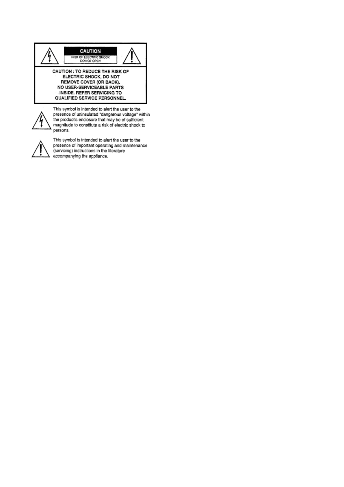
Explanation of Safety Related Symbols
■
Manual contents are subject to change without notice
■
4
Page 5
y
y
y
y
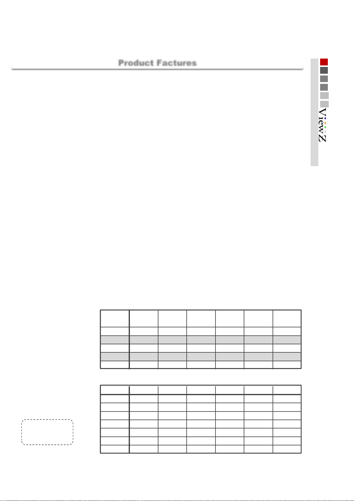
Product features
W
■
Product Factures
01 Getting Started
aveform
Vectorscope
16ch
16Channel, De-Embedded Audio Selec ted Out.
1:1 Pixel
H/V Dela
Displays the lume (Y " ) and Chroma (Cb/Cr) components of the input video signal as a form of waves.
Displays an X-Y plot of two signal, which c an receal details about the relationship between two signals.
1:1 pixel mode displays the original i mage resolution without scal ing to match a certain res ol ution or an aspect ratio.
View the blanking area and syncronize signals by displaying the horizontal and vertical intervals in the center of
the screen.
Screen Color Mode
IPS LCD Panel
Tally Lamp
Red, Green Support & UMD Tally Support
Blue, Red, Green and Mono
Wide view Angle
Programable Function ke
Maximum Brightness RJ-45 Remote Control
Marker4:3, 14:9, 15:9 and 16:9 area, line, safety, center markers display
UMD This monitor supports UMD
(Under Monitor Display)
function which displays Ancillary data at the bottom of the screen.
Source Alias Text Edit
ZOOM Select extension where you want to zoom(left or right).
Jog Dial Switch
Select an image of input signal & control on/off & switch to full screen.
Converter Solution Monitor Displa
SDI to HDMI SDI_A SDI_B
1
SDI to SDI
2
HDMI to SDI SDI_B
3
HDMI to HDMI HDMI
4
YPBPR to SDI YPBPR
5
YPBPR to HDMI DSUB
6
CVBS to SDI CVBS
7
CVBS to HDMI
8
DSUB to SDI
9
DSUB to HDMI SDI_A SDI_B
10
SDI_A
SDI
Output Source
▶ HDMI and DSUB VIDEO MODE ONLY
SDI_A
HDMI
SDI_B
HDMI
Output Source
●
Complete
○
ing
Not support
-
YPBPR
DSUB
CVBS
Display
●●●
●●●●●
●●●
○○
○○
○○○
●●●●
●●●●●●
●
○○
○○
○○○
●●●●●
●●
HDMI YPBPR DSUB CVBS
●●●
--
-
--
○
-
Monitor Displa
HDMI YPBPR DSUB CVBS
--
-
--
○
-
●
●
--
○○
○○
●●
●
--
○○
○○
●
5
Page 6
Getting Started
X
monitor info
■
monitor
Front
160.4 x 113.9 (mm)
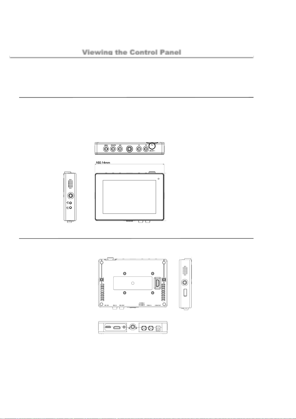
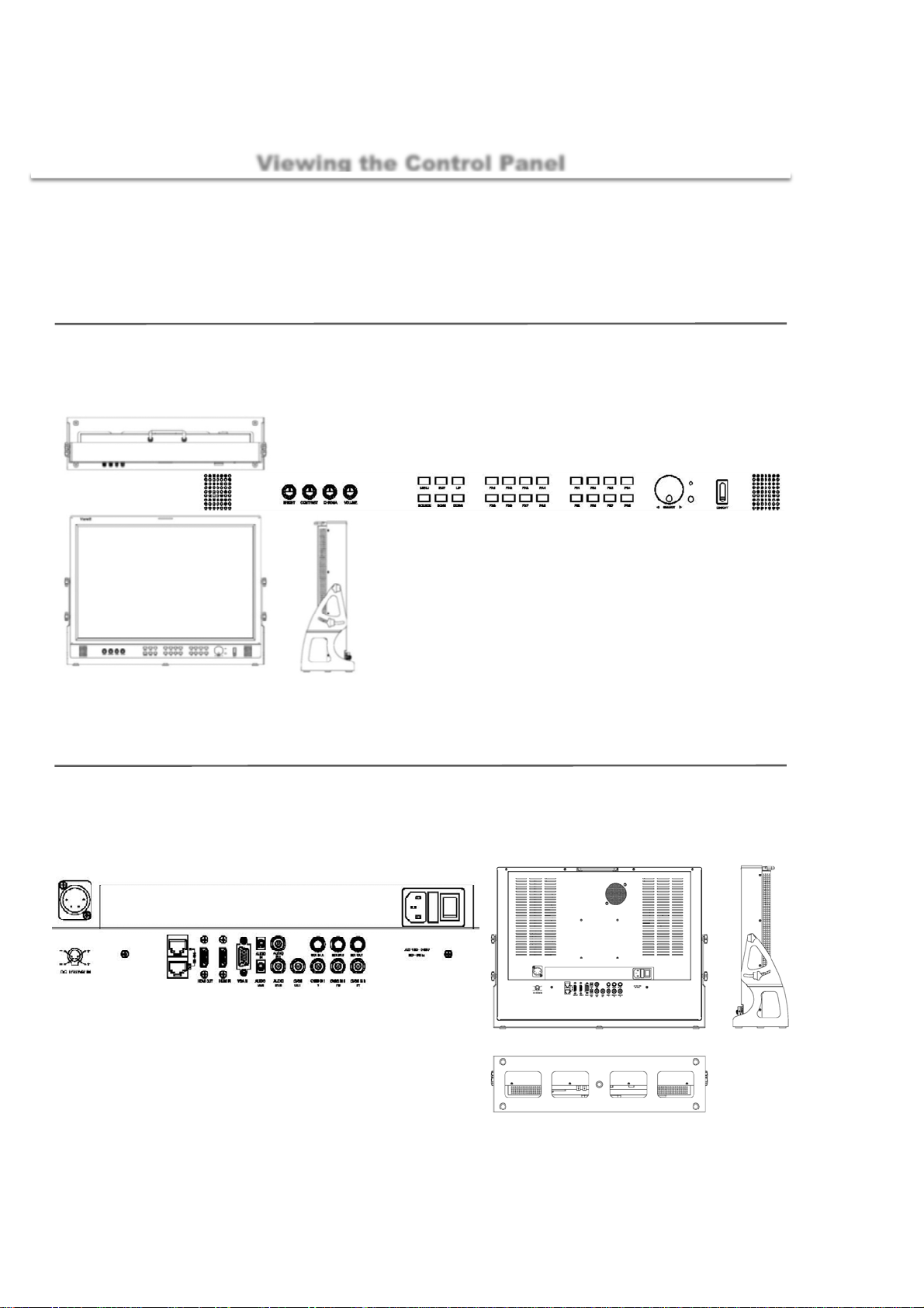
Viewing the Control Panel
OBM-056-XXXX
Stand
160.4 x 113.9 (mm)
1. Main menu open
2. Source select
3. Main menu open
4. Mount pem
5. Function key F1
6. Function key F2
7. Menu control Jog
Rear
8. Speaker
9. Mount pem
10. Audio in
11. Audio out
1. Sun Hood
2. V mount
12. Tally display
3. Service port
4. Speaker
5. Mount pem
6. On/Off switch
10. Mount pem
11. SDI Out
12. SDI in
7. HDMI out
8. HDMI in
9. Component, si te i n
13. DC 12V in
6
Page 7
monitor info
X
■
monitor
Front
221.5 x 126 (mm)
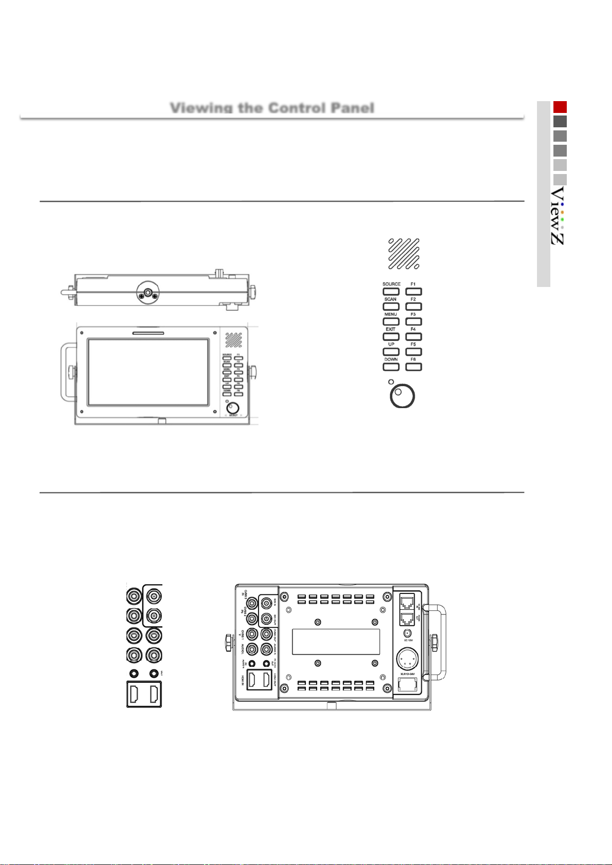
Viewing the Control Panel
OBM-070-XXXX
Stand
221.5 x 136 (mm)
01 Getting Started
Rear
1. Mount pem
2. Tally display
3. Speaker
4. Source select
6. Rato scan choice
8. Main menu open
10. EXIT
12. UP
14. DOWN
14. Power LED
5. Function key F1
7. Function key F2
9. Function key F3
11. Function key F4
13. Function key F5
15. Function key F6
15. Menu control Jog
1. Component [ Pr ], CVBS 3 i n
3. Component [ Pb ], CVBS 2 in
5. Component [ Y ], CVBS 1 in
7. Audio in L
9. PC Audio in
11. HDMI in
2. SDI signal in
4. SDI signal out
6. Composite out
8. Audio in R
10. PC Audio out
12. HDMI out
13. V mount
14. RS-485 IN
15. RS-485 OUT
16. DC 12V Power i n
17. XLR Power i n
18. On/Off switch
7
Page 8
Getting Started
X
monitor info
■
monitor
Front
221.5 x 218.5 (mm)
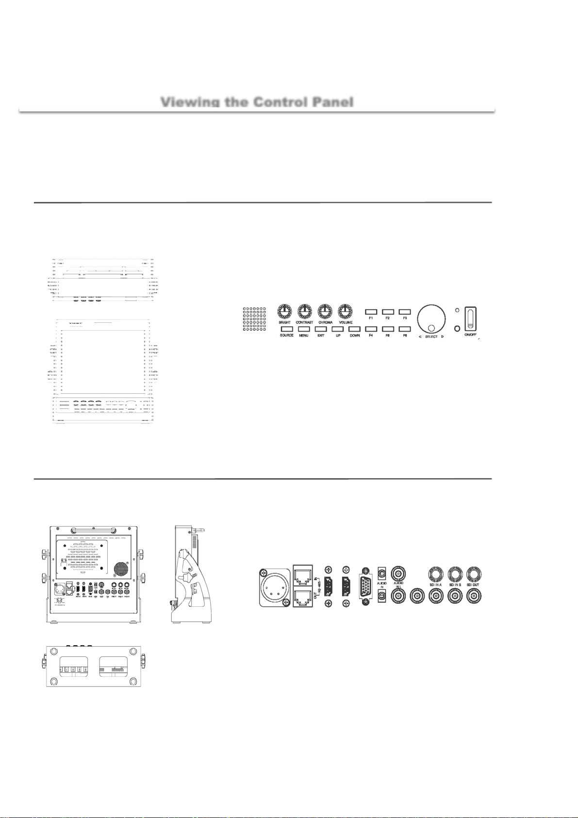
Viewing the Control Panel
OBM-097-XXXX
Stand
221.5 x 230.5 (mm)
1. Brigth contr ol
9. Speaker out
10. Source select
2. Contrast cont rol
11. Main menu open
3. Chroma control
4. Volume control
12. EXIT
13. UP
14. DOWN
5. Function F1
15. FunctionF4
6. FunctionF2
16. Function F5
7. Function F3
17. Function F6
8. Power LED
18. Menu control JOG
19. IR Sensor
20. On/Off switch
Rear
1. RS-485 IN
11. VGA in
7. XLR Power in
8. RS-485 out
9. HDMI out
10. HDMI in
2. Audio in
12. Audio out
3. Audio in L
13. Audio in R
14. Composite out
4. SDIin A
15. CVBS IN 1, Component [ Y ]
5. SDI in B
6. SDIout
16. CVBS IN 2, Component[ Pb ]
17. CVBS IN 3, Component [ Pr ]
8
Page 9
monitor info
X
■
monitor
Front
443 x 308 (mm)
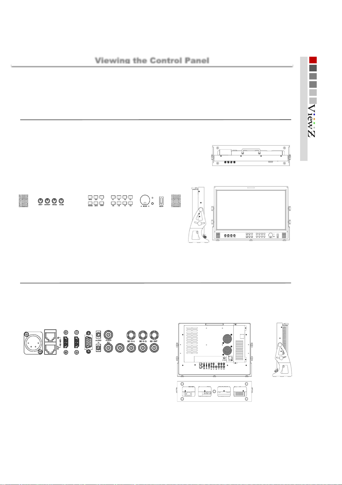
Viewing the Control Panel
OBM-185-XXXX
Stand
443 x 318 (mm)
01 Getting Started
13. Speaker out
Rear
2. Contrast cont rol
3. Chroma control
1. Brigth contr ol
4. Volume control
1. RS-485 IN
5. MENU
6. EXIT
14. Source
15. Scan
8. Function FA1
9. FunctionFA2
10. Function FA3
18. FunctionFA6
11. Function FA4
19. Function FA7
20. Function FA8
4. SDIin A
7. UP
17. Function FA5
16. Down
3. Audio in L
2. Audio in
12. Power LED
21. Menu control JOG
22. IR Sensor
23. On/Off switch
24. Speaker out
5. SDI in B
6. SDIout
7. XLR Power in
8. RS-485 out
9. HDMI out
10. HDMI in
12. Audio out
14. Composite out
15. CVBS IN 1, Component [ Y ]
16. CVBS IN 2, Component[ Pb ]
17. CVBS IN 3, Component [ Pr ]
9
13. Audio in R
11. VGA in
Page 10
Getting Started
X
monitor info
■
Viewing the Control Panel
OBM-240-XXXX
monitor
Front
563 x 410 (mm)
17. Speaker out
1. Brigth contr ol
Stand
2. Contrast cont rol
3. Chroma control
563 x 420 (mm)
4. Volume control
5. MENU
6. EXIT
18. Source
19. Scan
7. UP
20. Down
8. Function FA1
9. FunctionFA2
21. Function FA5
22. FunctionFA6
10. Function FA3
11. Function FA4
23. Function FA7
24. Function FA8
13. FunctionFB2
12. Function FB1
25. Function FB5
26. FunctionFB6
14. Function FB3
15. Function FB4
27. Function FB7
28. Function FB8
16. Power LED
29. Menu control JOG
31. On/Off switch
30. IR Sensor
32. Speaker out
Rear
1. RS-485 IN
7. XLR Power in
8. RS-485 out
9. HDMI out
10. HDMI in
3. Audio in L
2. Audio in
11. VGA in
12. Audio out
4. SDIin A
5. SDI in B
6. SDIout
15. CVBS IN 1, Component [ Y ]
13. Audio in R
14. Composite out
16. CVBS IN 2, Component[ Pb ]
17. CVBS IN 3, Component [ Pr ]
18. AC JACK
19. AC On/Off
10
Page 11

X
X
X
X
Basic Information
Initial setup
■
When the monitor is initially turned on, follow the instruction below by first pressing the MENU button.
01 Getting Started
Selecting a language
1
Press the UP or DOWN t o control, then press SOURCE to select the desired Language.
To reset this feature.
MENU Setting Load Sys Default
2
3
OBM-240-XXXX
Selecting Input
Function key
FA1 HDMI Output FA2 Aspect
FA3 Center Maker FA4 Safety Area
FA5 Marker FA6 Waveform
FA7 Vectorscope FA8 UMD
FB1 Audio Lvl Meter FB2 Timecode
FB3 HDMI CSC FB4 Zoom Mode
FB5 Blue/Mono FB6 H/V Delay
FB7 Max Bright FB8 SDI Output
▶▶
To select a source, please press External key.
The monitor is Default Function key.
Programmable key
Fixed Key
OBM-185-XXXX
F1 Blue/Mono F2 H/V Delay
F3 Max Bright F4 SDI Output
F5 HDMI Output F6 Aspect
F7 Center Maker F8 Safety Area
OBM-097-XXXXX, OBM-070-XXXX
F1 Blue/Mono F2 H/V Delay
F3 Max Bright F4 SDI Output
F5 HDMI Output F6 Aspect
OBM-056-XXXX
F1 Blue/Mono F2 H/V Delay
Programmable Key
Programmable Key
Programmable Key
11
Page 12

Getting Started
Display information
■
■
Setting information you have entered are displayed on the screen with graphs and texts.
1234 5
Basic Information
6
7
1 2345
Audio Level
meter [ Left ]
CH-1
CH-3
CH-5
CH-7
CH-9
CH-11
CH-13
CH-15
Center Maker Tally Display Timecode Display Audio Level
meter [ Right ]
6
Video Signal information Graph
[ Waveform _ LUMA, Cb, Cr , Vectorscope ]
CH-2
CH-4
CH-6
CH-8
CH-10
CH-12
CH-14
CH-16
12
7
Monitor Source Action Information
UMD
Page 13

■
Connecting to BNC Signal Device
02 Connections
BNC
BNC SDI Input signal
Input Signal Formats
425M(3G)
4 : 2 : 2
425M(3G)
4 : 4 : 4
260M(1.5G)
4 : 2 : 2
274M(1.5G)
4 : 2 : 2
296M(1.5G)
4 : 2 : 2
125M(270M)
4 : 2 : 2
1080 60P
1080 50p
720 24p
720 25p
720 50p
720 60p
1080 23.98p
1080 23.98Psf
1080 24p
1080 25p
1080 30p
1080 50i
1080 60i
1035 60i
1080 24psf
1080 24p
1080 23.98p
1080 23.98Psf
1080 25p
1080 30p
1080 50i
1080 60i
720 60p
720 50p
720 30p
720 25p
720 24p
720 X 487 60i
720 x 507 60i
3Gbps ~ 270Mbps
OBM-056 OBM-070
○○○○
○○○○○
○○○○
○○○○○
○○○
○○○○○
○○○○○
○○○○○
○○○○○
○○○○○
○○○○○
○○○○○
○○○○○
○○○○
○○○○○
○
○○○○○
○○○○○
○○○○○
○○○○○
○○○
○○○○○
○○○○
○○○○○
○○○
○○○○○
○○○○○
○○○○
○○○○○
○○○○
OBM-097 OBM-185 OBM-240
○○
○○
○○
○
○
○
○
○
13
Page 14

Connections
BNC
■
Connecting to BNC Signal Device
BNC SDI Output signal
Output Signal Formats
425M(3G)
4 : 2 : 2
425M(3G)
4 : 4 : 4
260M(1.5G)
4 : 2 : 2
274M(1.5G)
4 : 2 : 2
296M(1.5G)
4 : 2 : 2
125M(270M)
4 : 2 : 2
1080 60P
1080 50p
720 24p
720 25p
720 50p
720 60p
1080 23.98p
1080 23.98Psf
1080 24p
1080 25p
1080 30p
1080 50i
1080 60i
1035 60i
1080 24psf
1080 24p
1080 23.98p
1080 23.98Psf
1080 25p
1080 30p
1080 50i
1080 60i
720 60p
720 50p
720 30p
720 25p
720 24p
720 X 487 60i
720 x 507 60i
3Gbps ~ 270Mbps
OBM-056 OBM-070 OBM-097 OBM-185
○○○○○
○
○○○○
○○○○○
○○○○○
○○○○○
○○○○○
○○○○○
○○○○○
○○○○○
○○○○○
○○○○○
○○○○○
○○○○
○○○○○
○
○○○○○
○○○
○○○○○
○○○○○
○○○○○
○○○○○
○○○○
○○○○○
○○○
○○○○○
○○○○○
○○○○
○○○○○
○○○○
○○○○
○○
○○
OBM-240
○
○
○
○
14
Page 15

■
HDMI
HDMI Input signal
Output Signal
Formats
1080 60P
1080 50p
720 24p
720 25p
720 50p
720 60p
1080 24p
1080 25p
1080 30p
1080 50i
1080 60i
1035 60i
1080 24psf
1080 24p
1080 25p
1080 30p
1080 50i
1080 60i
720 60p
720 50p
720 30p
720 25p
720 24p
720 X 487 60i
720 x 507 60i
640 X 480
720 X 400
800 X 600
1024 X 768
1280 X 768
1360 X 768
1920 X 1080
1920 X 1200
Connecting to HDMI Signal Device
OBM-056 OBM-070
○○○○○
○○○○○
○○○○○
○○○○○
○○○○○
○○○○○
○○○○○
○○○○○
○○○○○
○○○○○
○○○○○
○○○○○
○○○○○
○○○○○
○○○○○
○○○○○
○○○○○
○○○○○
○○○○○
○○○○○
○○○○○
○○○○○
○○○○○
○○○○○
○○○○○
○○○○○
○○○○○
○○○○○
○○○○○
○○○○○
○○○○○
○○○○○
○○○○○
OBM-097 OBM-185 OBM-240
02 Connections
15
Page 16

Connections
HDMI
■
HDMI Output signal
Output Signal
Formats
1080 60P
1080 50p
720 24p
720 25p
720 50p
720 60p
1080 24p
1080 25p
1080 30p
1080 50i
1080 60i
1035 60i
1080 24psf
1080 24p
1080 25p
1080 30p
1080 50i
1080 60i
720 60p
720 50p
720 30p
720 25p
720 24p
720 X 487 60i
720 x 507 60i
640 X 480
720 X 400
800 X 600
1024 X 768
1280 X 768
1360 X 768
1920 X 1080
1920 X 1200
Connecting to HDMI Signal Device
OBM-056 OBM-070 OBM-097 OBM-185
○○○○○
○○○○○
○○○○○
○○○○○
○○○○○
○○○○○
○○○○○
○○○○○
○○○○○
○○○○○
○○○○○
○○○○○
○○○○○
○○○○○
○○○○○
○○○○○
○○○○○
○○○○○
○○○○○
○○○○○
○○○○○
○○○○○
○○○○○
○○○○○
○○○○○
○○○○○
○○○○○
○○○○○
○○○○○
○○○○○
○○○○○
○○○○○
○○○○○
OBM-240
16
Page 17

■
Connecting to VGA Signal Device
02 Connections
VGA
VGA Input signal
1.0Vpp (G with Sync), 0.7V pp ( B,R)
Input Signal Formats Frequency HF
640 X 400 59.779Hz 29.531 59. 779
720 X 400 85.038Hz 37.927 85. 038
800 X 600 60Hz 37.879 60.317
1024 X 768 49.866Hz 39.444 49.866
1024 X 768 60Hz 47.712 60.015
1152 X 720 60Hz 44.398 59.916
1152 X 864 75Hz 67.500 75.000
1280 X 720 30Hz 22.500 30.000
1280 X 768 60Hz 47.396
1280 X 1024 60Hz 63.981 60.020
1360 X 768 50Hz 39.499 49.936
1360 X 768 75Hz 60.143 74.999
1400 X 1050 60Hz 64.744 59.948
1440 X 480 60Hz 15.734 59.939
1680 X 1050 59.94Hz 64.742 59. 946
1600 X 1200 60Hz 75.000 60.000
1920 X 1080 60Hz 66.647 59.988
1920 X 1200 60Hz 74.099 59.999
VF
59.935
OBM-097 OBM-185 OBM-240
○
○○○
○○
○○○
○○
○○
○○
○○○
○○
○○○
○○
○○○
○○
○○○
○○
○○○
○○
○○○
○○
○
○
○
○
○
○
○
○
○
17
Page 18

Connections
Connecting to Component Signal Device
Component
■
Component Input signal
Input Signal Formats
480 50i
480 60i
480 60p
576 50i
576 50p
720 50p
720 60p
1080 50i
1080 60i
1080 50p
1080 60p
OBM-056 OBM-070 OBM-097 OBM-185 OBM-240
1.0Vpp (Y with Sync), 0. 7V pp ( Pb,Pr)
○○○○○
○○○○○
○○○○○
○○○○○
○○○○○
○○○○○
○○○○○
○○○○○
○○○○○
○○○○○
○○○○○
18
Page 19

Composite
■
Connecting to Composite Signal Device
02 Connections
Composite Input signal
Input Signal Formats
NTSC
PAL
SECAM
1.0Vpp (with Sync)
OBM-056 OBM-070
○○○○○
○○○
○○○○○
OBM-097 OBM-185 OBM-240
○○
19
Page 20

Connections
RJ-45 Remote Control
■
RJ-45
Buyer Option
Customer's option
20
Page 21

VIDEO
03 MENU Features
Mode
■
Select your preferred picture type.
[ User, Dynamic, Standard, Movie, Mild ]
Main ▶ Video ▶ Mode
Brightness
Controls the degree of brightness between [ 0min ~ 100max ]
Contrast
Controls the contrast ratio between [ 0min ~ 100max ]
Color Temp
■
Select your preferred Temp type.
[ User, 9300K, 7500K, 6500K ]
RED
GREEN
BLUE
Color Only
■
Select your preferred Color type.
[ Red, Green, Blue, Mono ]
Main ▶ Video ▶ Color Temp
Controls RED, GREEN, BLUE color.
The value is selectable between [ 0min ~ 100max ]
Adjusts R, G, B color of bright section.
Main ▶ Video ▶ Color Only
DSUB
■
Select DSUB( VGA ) Function
Main ▶ Video ▶ DSUB
Auto Progress
H Posi
V Posi
Controls the H Position between
Controls the V Position between
Auto Detect position & phase
Frequency
Controls the contrast ratio between [-100min ~ 100max ]
Phase
Controls PHASE value (hue) between [ -32min ~ 31max ]
768 Mode
Forcibly change the input resolution
[ Auto, 1024x768, 1224x768, 1280x768, 1360x768, 1366x768 ]
NTSC Setup
■
This item sets IRE value under NTSC mode between
Off ( 0 IRE ) and On ( 7.5 IRE )
Main ▶ Video ▶ NTSC Setup
[ -100min ~ 100max ]
[ -100min ~ 100max ]
21
Page 22

Aspect
Scan
■
This product supports various scan modes.
[ Zreoscan, Underscan, Overscan ]
Main ▶ Aspect ▶ Scan
Zreoscan Underscan Overscan
Zooms in/out of the image without
changing the aspect ratio.
Aspect
■
Used to change the Aspect between.
[ fullscreen, 16:9, 4:3, 1:1 ]
Main ▶ Aspect ▶ Aspect
▶ EX monitor - 0BM-185 Display Panel & S ource 16 : 9
Zooms in/out of the image without
changing the aspect ratio. Also,
displays the data at the top of the
horizontal blanking block.
▶ EX monitor - OBM-185 Display Panel & S ource 16 : 9
Zooms in/out of the image to 96%
of its original size without changing
the aspect ratio of.
Fullscreen 16 : 9 4 : 3
Enlarges the aspect ratio of the
picture to fit the entire screen.
1 : 1
1:1 pixel mapping of original image.
This feature is available only when
the size of the original image is
bigger than the screen size.
Stretches the image in “4:3 mode”
to fit to 16:9 aspect ratio.
Cuts left and right of the original
image to fit to 4:3 aspect ratio.
22
Page 23

St
Aspect
03 MENU Features
Anamorphic
■
Main ▶ Aspect ▶ Anamorphic
Select your preferred Anamorphic type.
Zoom Mode
■
Main ▶ Aspect ▶ Zoom Mode
Used to change the display ratio between.
[ zoom,Pixel To Pixel, Disable ]
▶ EX monitor -OBM-185 Display Panel & S ource 16 : 9
1
1.37 : 1
2
ep
down
Vertical
▶ EX monitor - OBM-185 Display Panel & S ource 16 : 9
3
4
5
6
7
8
9
1.50 : 1
1.55 : 1
1.60 : 1
1.66 : 1
1.75 : 1
1.85 : 1
2.00 : 1
2.20 : 1
10
11
12
13
14
15
16
17
2.35 : 1
2.37 : 1
2.39 : 1
2.40 : 1
2.55 : 1
2.59 : 1
2.76 : 1
3.56 : 1
Pixel To Pixel Zoom
▼
Display Panel reduced the input
signal on the screen (Scale) as it
does not appear on the screen to
the size of the input feature.
▼
Zoom Ratio
Used to change the Zoom Ratio between. [ 0min ~ 50max ]
H Position
adjust the horizontal position of image.
[ 0min ~ 50max ]
V Position
adjust the vertical position of image.
[ 0min ~ 50max ]
23
Page 24

TBD
SDI Audio
■
Pri-Group
Sec-Group
Outupt Channel
Sound
Main ▶ Sound ▶ SDI Audio
Speaker Out
■
Volume
■
Main ▶ Sound ▶ Speaker Out
Main ▶ Sound ▶ Volume
24
Page 25

A/V Scope
03 MENU Features
Scope Position
■
Select in Scope location
Scope Mode
■
TBD
Line Number
■
TBD
Waveform Enable
■
Main ▶ A/V Scope ▶ Scope Position
Main ▶ A/V S c ope ▶ Mode
Main ▶ A/V S c ope ▶ Line Number
Main ▶ A/V Scope ▶ Wavef orm Enable
L/T
L/B
R/T
R/B
Select Waveform [ On, Off ]
Waveform
Waveform Source
■
Main ▶ A/V Scope ▶ Waveform Source
[ LUMA, Cb, Cr, LUMA+Cb+Cr ]
LUMA Cb Cr
Vector Enable
■
Main ▶ A/V Scope ▶ Vector Enable
Select Vector [ On, Off ]
Vector
Audio Level Meter
■
Main ▶ A/V Scope ▶ Audio Level Meter
Select Audio Level Meter [ On, Off ]
25
Page 26

Setting
Language
■
language Selection
Osd Blend
■
OSD the transparency selection
Load Sys Default
■
Initializ monitor
Background Gray
■
SOURCE BLANK section, select grayscale [ 0min ~ 7max ]
Gamma
■
TBD
Gamma Curve
■
TBD
Bklight Dimming
■
Backlight brightness control [ 0min ~ 100max ]
Main ▶ Setting ▶ Language
Main ▶ Setting ▶ Osd Blend
Main ▶ Setting ▶ Load Sys Default
Main ▶ Setting ▶ Background Gray
Main ▶ Setting ▶ Gamma
Main ▶ Setting ▶ Gamma Curve
Main ▶ Setting ▶ Bklight Dimming
Volume Lock
■
Select outside Volume lock function.
[ Brightness, Contrast, Color ]
Power Saving
■
TBD
Temperature Ctrl
■
Main ▶ Setting ▶ Volume Lock
Main ▶ Setting ▶ Power Saving
Main ▶ Setting ▶ Temperature Ctrl
Hysteresis
Shutdown Ref and Auto Fan Ref for Hysteresis temperature settings
[ 2.0℃ min ~ 6.0℃ max ]
Shutdown Ref
panel shutdown temperature setting. [ 70℃min ~ 90℃max ]
Auto Fan Ref
Fan On / Off Standard temperature setting. [ 40℃min ~ 60℃max ]
Fan On/Off
Fan function select [ Auto, Off, On ]
Fan Speed
Fan speed selection [ auto, Slow, Nomal, Fast ]
Main Temperature
Check the internal temperature of the monitor
26
Page 27

Advanced
03 MENU Features
HDMI Output
■
Select the output source from the HDMI Output port
Main ▶ Advanced ▶ HDMI Output
Source
Select output signal [ Disable, SDI, Display, HDMI/ADC ]
Color Format
Select color space [ RGB, 4:2:2, 4:4:4 ]
RGB Range
Selet color range of RGB color format
[ 0-255, 16-235 ]
YCbCr Range
Select color range of 422 or 444 color format
[ Video(16~235), Extended(1~254), Full(0~255) ]
HDMI Input
■
Select input source from HDMI input port
Main ▶ Advanced ▶ HDMI I nput
RGB Range
Select color range with HDMI input format of RGB [ 0-255, 16-235 ]
YCbCr Range
Select color range with HDMI input format of 422 or 444 [ Video(16~235), Extended(1~254), Full(0~255) ]
SDI Output / Input
■
Select in/output source from SDI port
Main ▶ Advanced ▶ SDI Output / Input
Output Source
Select output signal [ Disable, SDI, HDMI/ADC ]
Output Range
Select color range of output signal [ Video(16~235), Extended(1~254), Full(0~255) ]
Input Range
Select color range of input signal [ Video(16~235),
Extended(1~254), Full(0~255) ]
Timecode
■
Select Timecode [ On, Off ]
Source Alias
■
Enter an alias for the input source.
▶ Source alias modifications automatically reflected on UMD
Timecode Type
■
TBD
UMD
■
This monitor supports UMD(Under Monitor Display) funtion
which displays Ancillary data at the button of the screen.
Main ▶ Advanced ▶ Timecode
Main ▶ Advanced ▶ Source Alias
Main ▶ Advanced ▶ Timecode Type
Main ▶ Advanced ▶ UMD
Enable
Color
Blend
Position
UMD function On / Off
UMD Color Selection
Blend (UMD Transparency ) On/ Off
UMD slot selection
27
Page 28

Function key
Function Key
■
All front function keys are programmable with any features
that included in the product,
But only one feature can be assigned per one function key.
[ Blue/ mono, H/V Delay, Max Brigth, SDI Output,
HDMI Output, Aspect, Center Marker, Safety Area,
Marker, Waveform, Vectorscope, UMD, Audio Lvl
Meter, Timecode, HDMI CSC, Zoom mode, Still,
HDMI, SDI CH1, SDI CH2, DSUB ]
Marker
■
Lines input on the screen according to certain percentage
Marker Type
Main ▶ Marker
Main ▶ Function Key
based on the percentage of panel
[ Off, 16:9, 4:3, 15:9, 14:9, 13:9,
1.85:1, 2.35:1 ]
Marker
Safety Area
Center Marker
Marker Property
Safety Wide
Safety to Marker
Select input of the Safety Resolution rate
[ Off, 95%, 93%, 90%, 88%, 85%,
80%, EBU Action, EBU Graphic ]
On / Off Center Marker
TBD
TBD
TBD
28
Page 29

Accessory
■
Accessory
04 Other Information
Wallmount Hardware 19" Rack Mountable Camera Mount
Protective Carrying Bag Protective Sun Visor Battery Mount
AC Power Cable ND Filter AR Glass
Adaptor
29
Page 30

Specifications
■
Specifications
Lcd spec
Case features
Convertor
features
INPUT
Connector
Product
Resolution
Back light Type
Color Depth
viewing Angle
Luminance (Max.)
Contrast Ratio
Display Area
monitor Dim
Stand Dim
Weight (g)
SDI to HDMI
SDI to SDI
HDMI to SDI
HDMI to HDMI
Comp to SDI
Comp to HDMI
CVBS to SDI
CVBS to HDMI
VGA to SDI
VGA to HDMI
SDI BNC
Analog BNC
( CVBS,Component )
Audio Phone jack
(Analog Stereo )
Size
HDMI
D-SUB
OBM-056 OBM-070 OBM-097 OBM-185 OBM-240
5.6 inch 7 inch 9.7 inch 18.5 inch
1280 x 800 (16:10) 1024 x 600 (16:9) 1024 x 768 (4:3) 1366 X 768 (16:9) 1920 X 1200 (16:10)
LED LED LED
16.7M (Dither 8 Bit) 16.7M ( 8 Bit ) 16.7M (Dither 8 Bit)
170°(H) / 170°(V) 170°(H) / 170°(V) 178°(H) / 178°(V) 178°(H) / 178°(V) 178°(H) / 178°(V)
(Typ.)
300 cd/m² 400 cd/m² 400 cd/m² 250 cd/m² 400 cd/m²
500 : 1 800 : 1 600 : 1 1000 : 1 1000 : 1
160.4 x 113.9 (mm) 221.5 x 126 (mm) 221.5 x 218.5 (mm) 443 x 308 (mm)
160.4 x 113.9 (mm) 221.5 x 136 (mm) 221.5 x 230.5 (mm) 443 x 318 (mm) 563 x 420 (mm)
627.5 916.5 2750
○○○○○
○○○○○
○○○○
○○○
○○○○○
○○○○○
○○○○○
○○○○○
--○○○
--○○○
LED CCFL
16.7M (8 Bit) 1.07B (10 Bit)
6500 8040
○○
1122
11111
--1
3
(Phone jack gender)3( RCA JACK )
2
(Phone jack gender)
1111
333
11
24 inch
563 x 410 (mm)
○
2
30
OUTPUT
Connector
Speaker
INPUT
POWER
Audio BNC jack
(Component audio L, R )
SDI BNC
HDMI
Composite BNC
Audio Phone jack
(Analog Stereo )
-
1111
1
( MINI HDMI )
--1
11111
2
( RCA JACK )
1111
Built in Speaker 1W X 2 2W X 1 2W X 1
AC 100~240V
DC 12V/24V
( XLR, DC JACK )
--○○○
○ 12V
( DC JACK )
○ 12V/24V
( DC JACK , XLR )
○ 12V/24V
( DC JACK , XLR )
222
1
11
2W X 2
○ 24V ( XLR ) ○ 24V ( XLR )
2W X 2
Page 31

Operating Instructions
Broadcasting Monitor User guide
Thank you
31
 Loading...