

Page 1
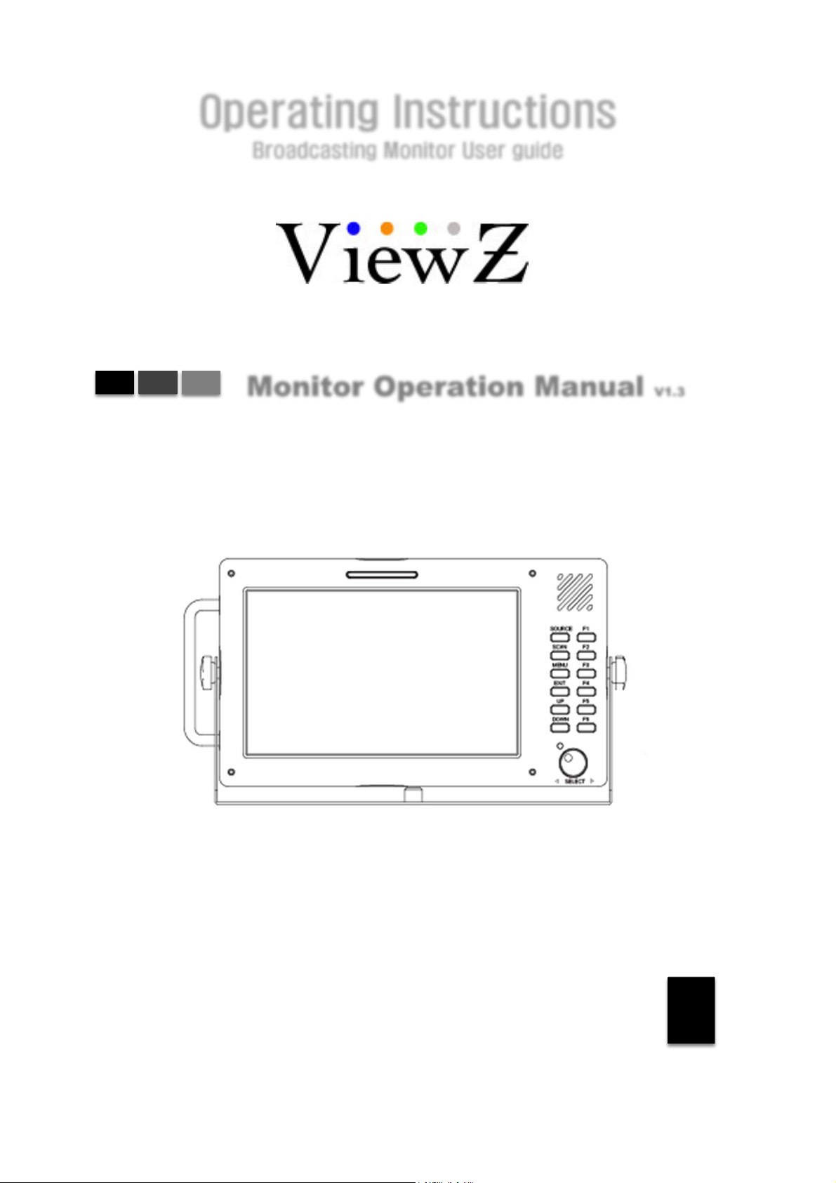
Operating Instructions
Broadcasting Monitor User guide
Monitor Operation Manual V1.3
VZ-070-TBBSV
VZ-070-TSBSV
3G
1
Page 2
Contents
Getting Started
Caution
Product features
Monitor View
Initial Setup
Basic Information Advanced
3
5
6
7
816
Connections
Connecting to BNC Signal Device
SDI input signal Format
SDI output signal Format
Connecting to HDMI Signal Device
HDMI input signal Format
HDMI output signal Format
Connecting to Component Signal Device
Component input signal Format
Connecting to Composite Signal Device
Composite input signal Format
9
9
10
10
MENU Features
Video
Color Temp
Brightness
Contrast
Color
Color Only
NTSC Setup
Max Bright
Aspect Menu
Scan
Aspect
Anamorphic
Zoom Mode
H/V Delay
Still
A/V Scope
Scope Position
Waveform Enable
Waveform Source
Vector Enable
Audio Level Meter
11
12
14
Setting
OSD
Load System Default
Bklight Dimming
Misc
Input Output
Timecode
Source Alias
UMD
System Info
H Flip
Test Pattern
Function Key
Marker
Handheld
DSLR Scale
Peaking
Peaking Sensitivity
Peaking Color
Peaking Blinking
False Color
False Color U/L
False Color L/L
False Color Palette
Limit Emphasis
False Color Blink
Limit Blink
Other Information
Accessory
Specification
15
17
17
18
19
20
Contents
2
Page 3

Caution
Caution
■
It is highly recommended to read and understand the cautions listed below thoroughly before you start using the
product. And if you are unclear with any parts of the cautions or have questions, please contact us.
■
Apparatus shall not be exposed to dripping or splashing and no objects filled with liquids, such as vases, shall be
placed on the apparatus.
■
WARNING – TO PREVENT FIRE OR SHOCK HAZARD DO NOT EXPOSE THE SET TO RAIN OR
MOISTURE.
■
"IMPORTANT SAFETY INSTRUCTIONS"
Read these instructions
□
Keep these instructions
□
Heed all warnings
□
Follow all instructions
□
Do not use this apparatus near water
□
Clean only with a dry cloth
□
Do not block any of the ventilation openings. Install in accordance with he manufacturer's instructions
□
□
Do not install near any heat sources such as radiators, heat registers, stoves, or other apparatus (including
amplifiers) that produce heat.
□
Do not defeat the safety purpose of the polarized or grounding type plug. A polarized plug has two blades
with one wider than the other. A grounding type plug has two blades and a third grounding prong. The wide
blade or the third prong is provided for your safety. When the provided plug does not fit into your outlet,
consult an electrician for replacement of the obsolete outlet
Caution
□
Protect the power cord from being walked on or pinched particularly at plugs, convenience receptacles, and
the point where they exit from the apparatus
Only use the attachments/accessories specified by the manufacturer.
□
□
Use only with a cart, stand, tripod, bracket, or table specified by the manufacturer, or sold with the apparatus.
When a cart is used, use caution when moving the cart/apparatus combination to avoid injury from tip-over.
□ Unplug this apparatus during lightning storms or when unused for long periods of time
□
Refer all servicing to qualified service personnel. Servicing is required when the apparatus has been
damaged in any way, such as power supply cord or plug is damaged, liquid has been spilled or objects have
fallen into the apparatus, the apparatus has been exposed to rain or moisture, does not operate normally, or
has been dropped.
□
The apparatus shall not be exposed to dripping or splashing and that no objects filled with liquids, such as
vases, shall be placed on the apparatus
□
Shall be connected to a MAINS socket outlet with a protective earthing Connection
□ The disconnect device shall remain readily operable
□ The socket-outlet shall be installed near the equipment and shall be easily accessible
3
Page 4
Caution (cont'd)
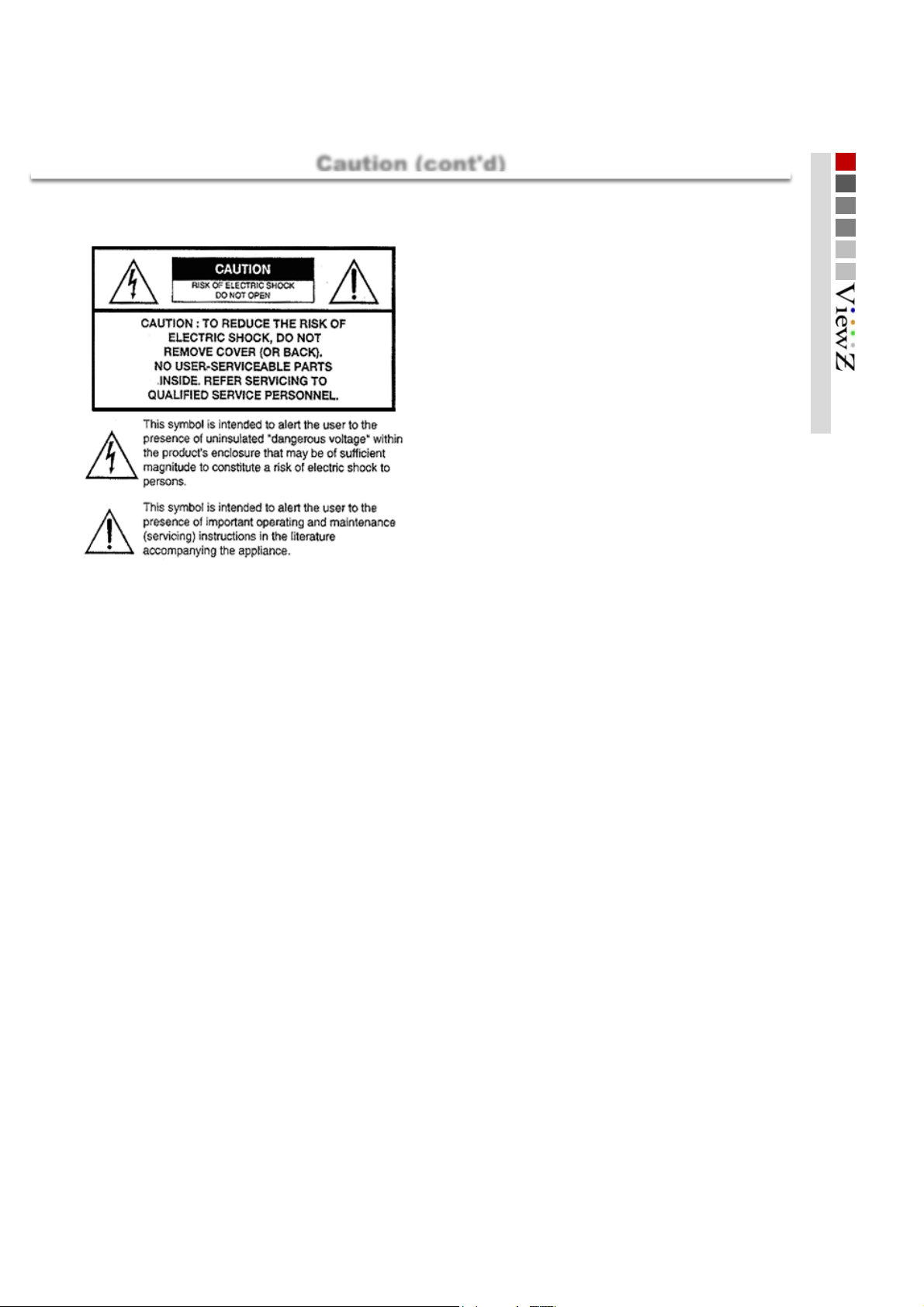
Explanation of Safety Related Symbols
■
Manual contents are subject to change without notice
■
Caution
4
Page 5

r
y
r
y
W
r
r
r
y
Product Features
■
Product Features
Product Features
Integrated Converte
Multi-Format Signal
3G-SDI: 3Gb/sec 4:4:4 HD
SDI-HDMI Loop Through
12Bit Internal Processing
2K Input Capabilit
Peaking / Focus Assist
DSLR Scaling
Actively scales live video images to reduce the black areas of the screen to allow for a ful screen 16:9
image
False Colors Filte
Under Monitor Displa
Menu Jog Congrol
aveform Monito
Vector Scope Monito
Pixel to Pixel Mapping
Integrated active SDI-HDMI and HDMI-SDI converter allows the transparent conversion of HD to
HDMI signal or conversion of HDMI back to HD format
ViewZ monitors are com patible with various sources incl udi ng
- HDMI (compatible with DVI)
- SDI signals: 3G(425A/B), HD, SD
- CVBS(composite) and YPbPr(component)
SMPTE 425 compliant HD display that supports frame rates of 50.60 in 1080p, 1080i, and
720p
Supports full SMPTE 425 signal conversion transparency from SDI to HDMI with test and
measurement overlays
Allows for color temperature and gamma encoding changes to be implemented quickly. Active
Video Looping supports full 1080p/60 frames on the HDMI output
2k content can be displayed on ViewZ monitors without the loss of HD signal by converting and
downscaling the content
Peaking filter shows if the image is out of focus in difficult wide full range DSLR shots by
highlighting areas that are out of focus with a cross stripe pattern
Color filtering allows users to display different areas of the images as different colors to set portions of
the scene as over or under exposed
UMD function displays ancilliary data at the bottom of the screen
Jog dial on the front of the monitor enables users to cont rol al l features
Onscreen display of video levels with respect to time, used to calibrate multiple camera setups and
vertical blanking level and col or burst
On-screen display of chrominance information in Cb and Cr channels. Display can be opaque or
solid against the visual di splay
1:1 pixel mode displays the original image resolution without scaling to match a certain resolution
or an aspect ratio
De-Embedded Audio Level Mete
Aspect Format Markers
Gamma Encoding Select
Time Code
H/V Dela
Time code reader displays embedded LTC or VITC format s
View the blanking area and syncronize signals by displaying the horizontal and vertical intervals in the center of
the screen
RJ-45 Remote Control
4:3, 14:9, 15:9, 16:9 etc . area, line, safety, center markers display
Range from 1.0 to 3.0 users selectable. Factory defaul t setting is 2.8
Plug in your RJ-45 connector to the back of the monitor and communicate with other ViewZ
monitors (RS-485 control / T al l y Li ght Control)
De-embedded audio selected out. Auto sensing to display three range meter of
up to 16 ch
* Does not support P.O.E.
5
Page 6
Exterior Information
X
■
monitor
Front
221.5 x 126 (mm)
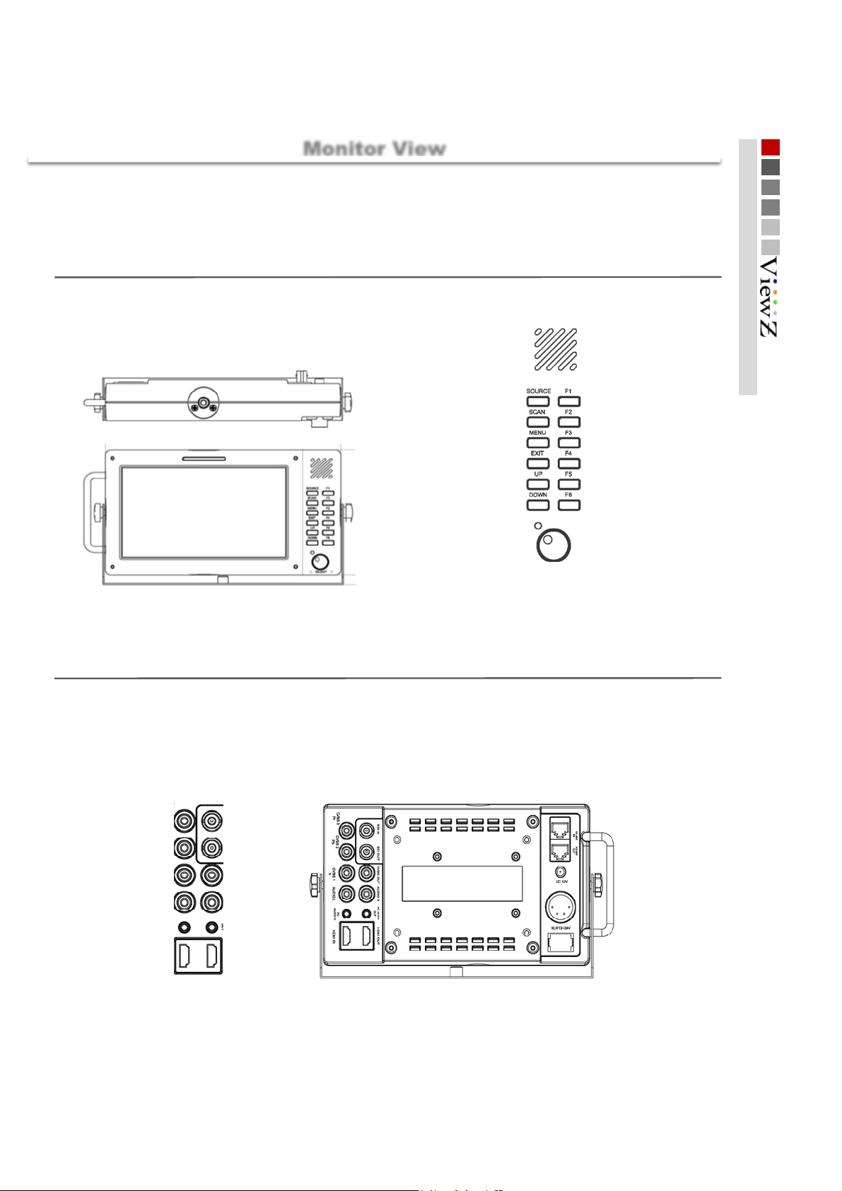
Monitor View
VZ-070XXXX
Stand
221.5 x 136 (mm)
Monitor View
Rear
1. Mount
2. Tally display
3. Speaker
4. Source select
6. scanchoice
8. Main menu open
10. EXIT
12. UP
14. DOWN
14. Power LED
5. Function key F1
7. Function key F2
9. Function key F3
11. Function key F4
13. Function key F5
15. Function key F6
15. Menu control Jog
1. Component [ Pr ], CVBS 3 i n
3. Component [ Pb ], CVBS 2 in
5. Component [ Y ], CVBS 1 in
9. PC Audio in
6
7. Audio in L
11. HDMI in
2. SDI signal in
4. SDI signal out
6. Composite out
8. Audio in R
10. PC Audio out
12. HDMI out
13. V mount
14. RS-485 IN
15. RS-485 OUT
16. DC 12V Power i n
17. XLR Power i n
18. On/Off switch
Page 7
X
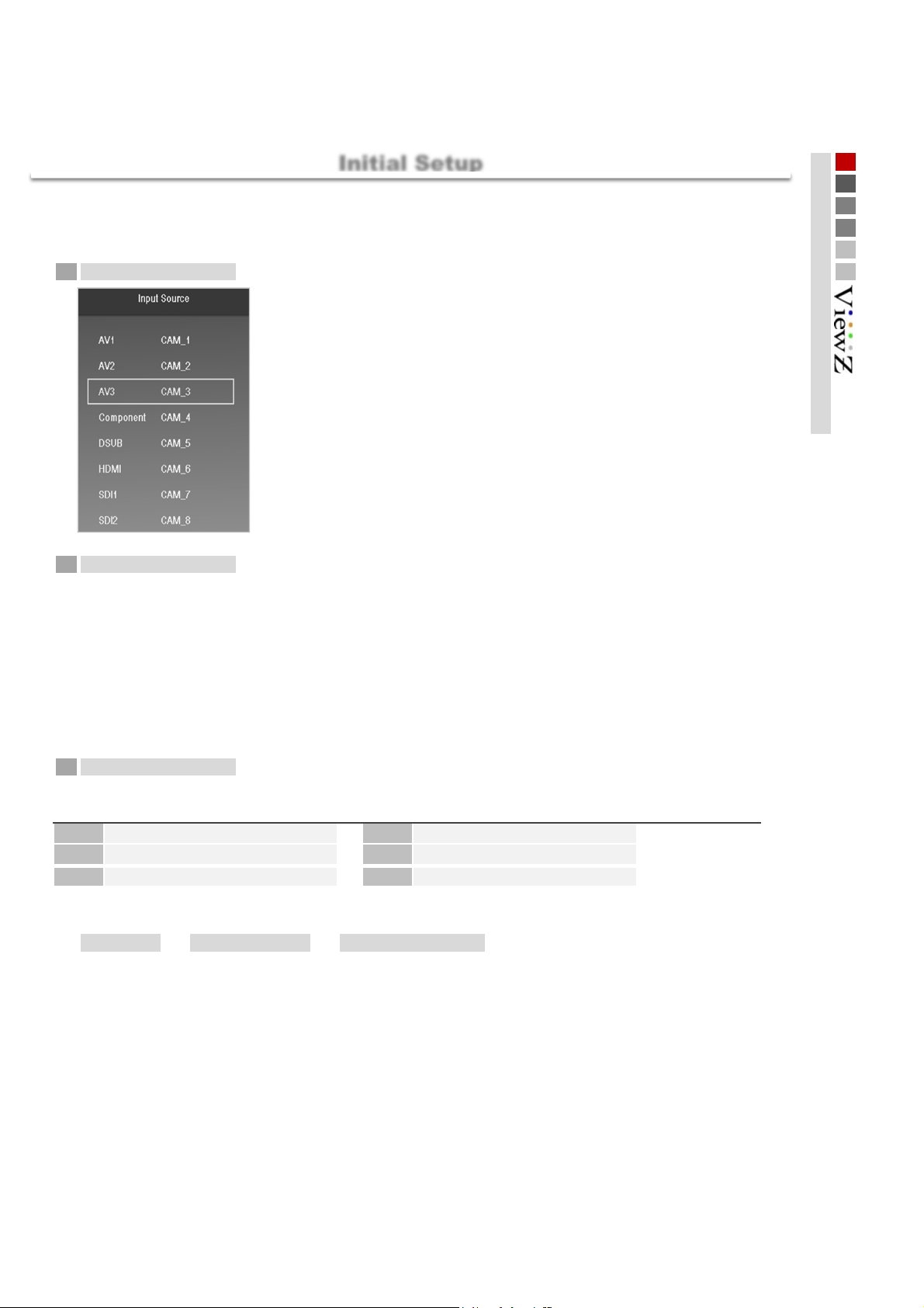
Initial Setup
First Steps
■
When the monitor is powered on and connected to your source,
1
Selecting Input
- To select your source, please press SOURCE button
- Turn the main jog to make your choice, and click the jog to select
- Factory default is HDMI. Please skip this step if you are connected to HDMI
source
Initial Setup
2
3
VZ-070XXXX
Menu Control
- Press the main jog on the front of the monitor for 2 seconds to enter or exit the menu
- Turn the jog to move around the menu
- Click the jog to make your selection
- Main jog allows users to move one step at a time. If you wish to move back to previous step in the menu, press
the jog for two seconds. If you want to exit the menu and restart, press exit button depending on where you are in
menu tree
- If you click the jog without entering the main menu, brightness, contrast, color, and volume control will be
available. For an example, click the jog 2 times to control contrst and 4 times to change volume
Function key
F1 Blue/Mono F2
F3 Max Bright
F5 HDMI Output
- Users can program 6 function buttons on the front by
MENU Function Key Function Key #
- All featuress in the monitor can be programmed in one of these six keys
▶▶
Factory default setting for programmable keys on the front of the monitor
H/V Delay
F4
F6
SDI Output
Aspect
7
Page 8

Display information
■
■
Settings you have entered are displayed on the screen with graphs and texts.
1234 5
Basic Information
Basic Information
6
7
1 2345
Audio Level
meter [ Left ]
CH-1
CH-3
CH-5
CH-7
CH-9
CH-11
CH-13
CH-15
Center Maker Tally Display
6
Video Signal information Graph
[ Waveform _ LUMA, Cb, Cr , Vectorscope ]
Timecode Display Audio Level
meter [ Right ]
CH-2
CH-4
CH-6
CH-8
CH-10
CH-12
CH-14
CH-16
7
Under Monitor Display including source resolution, signal coverting status, tally etc.
8
Page 9

Connecting to Various Signals
Connections
■
BNC
BNC SDI signal
Signal Formats
425M(3G)
4 : 2 : 2
425M(3G)
4 : 4 : 4
260M(1.5G)
4 : 2 : 2
274M
(1.5G)
4 : 2 : 2
296M(1.5G)
4 : 2 : 2
125M
(270M)
4 : 2 : 2
3Gbps~270Mbps
1080 60P
1080 50p
720 24p
720 25p
720 50p
720 60p
1080 23.98p
1080 23.98psf
1080 24p
1080 25p
1080 30p
1080 50i
1080 60i
1035 60i
1080 24psf
1080 24p
1080 23.98p
1080 23.98psf
1080 25p
1080 30p
1080 50i
1080 60i
720 60p
720 50p
720 30p
720 25p
720 24p
720 X 487 60i
720 x 507 60i
INPUT
○○
○○
○○
○○
○○
○○
○○
○
○
○
○
○
○
○
○
○
○
○
○
○
○
○
○
○○
○
○○
○○
○○
○○
OUTPUT
○
○
○
○
○
○
○
○
○
○
○
○
○
○
○
○
○
■
HDMI
HDMI signal
Signal Formats
1080 60P
1080 50p
720 24p
720 25p
720 50p
720 60p
1080 24p
1080 25p
1080 30p
1080 50i
1080 60i
1035 60i
1080 24psf
1080 24p
1080 25p
1080 30p
1080 50i
1080 60i
720 60p
720 50p
720 30p
720 25p
720 24p
720 X 487 60i
720 x 507 60i
640 X 480
720 X 400
800 X 600
1024 X 768
1280 X 768
1360 X 768
1920 X 1080
1920 X 1200
INPUT OUTPUT
○○
○○
○○
○○
○○
○○
○○
○
○○
○○
○○
○○
○○
○○
○○
○○
○
○○
○○
○○
○○
○○
○○
○○
○○
○○
○○
○○
○○
○○
○○
○○
○○
○
○
9
Page 10

Component
■
Connecting to Analog Signals
Connections
Composite
■
Component Input signal
Input Signal Formats
480 50i
480 60i
480 60p
576 50i
576 50p
720 50p
720 60p
1080 50i
1080 60i
1080 50p
1080 60p
VZ-070XXXXX
Composite Input signal
1.0Vpp (Y with Sync), 0. 7V pp ( Pb,Pr)
○
○
○
○
○
○
○
○
○
○
○
1.0Vpp (with Sync)
Input Signal Formats
NTSC
PAL
SECAM
VZ-070XXXXX
○
○
○
10
Page 11

VIDEO
Video
■
Color Temp
- Select your preferred color temperature settings
[ User, 9300K, 7500K, 6500K ]
RED gain
GREEN gain
BLUE gain
RED bias
GREEN bias
BLUE bias
Color Copy To
*IMPORTANT
Once user color temp overwrites factory default value of 6500K, 7500K, or 9300K, it will apply PERMANENT change
and monitor reset will NOT restore factory default values
■
Brightness
Main ▶ Video ▶ Color model
- adjusts R, G, B Gain
- selectable level between [ 0min ~ 100max ]
- adjusts R, G, B Bias or Offset
- selectable between [-50min ~ 50max ]
used to copy User color temp to 6500K, 7500K, or 9300K
Main ▶ Video ▶ Brightness
- adjust the brightness(offset)
- selectable level between [ 0min ~ 100max ]
- shortcut by clicking the main jog 1 time
■
Contrast
Main ▶ Video ▶ Contrast
- adjust the contrast
- selectable level between [ 0min ~ 100max ]
- shortcut by clicking the main jog 2 consecutive times
■
Color
Main ▶ Video ▶ Color
- selectable level between [ 0min ~ 100max ]
- shortcut by clicking the main jog 3 consecutive times
■
Color Only
- Select your preferred color type.
[ Color, Green, Red, Blue, Mono ]
NTSC Setup
■
- adjust IRE value under NTSC mode between Off ( 0 IRE ) and On ( 7.5 IRE )
Max Bright
■
- enabling this feature changes brightness to maximum level (100)
- disabling this feature will apply the previous brightness level
Main ▶ Video ▶ Color Only
Main ▶ Video ▶ NTSC Setup
Main ▶ Video ▶ Max Bright
11
Page 12

Aspect
Aspect
Scan
■
- This product supports various scan modes
[ Zreoscan, Underscan, Overscan ]
Main ▶ Aspect ▶ Scan
Zeroscan Underscan Overscan
Zooms in/out of the image without
changing the aspect ratio.
Aspect
■
- Used to change the display ratio between
[ fullscreen, 16:9, 4:3, 1:1 ]
Main ▶ Aspect ▶ Aspect
Fullscreen 16 : 9 4 : 3
Enlarges the aspect ratio of the
picture to fit the entire screen.
Zooms in/out of the image without
changing the aspect ratio. Also,
displays the data at the top of the
horizontal blanking edge.
Stretches the image in “4:3 mode”
to fit to 16:9 aspect ratio.
▶ VZ-185 for demonstration
Zooms in/out of the image to 96%
of its original size without changing
the aspect ratio.
▶ VZ-185 for demonstration
Cuts left and right of the original
image to fit to 4:3 aspect ratio.
1 : 1
1:1 pixel mapping of original image.
This feature is available only when
the size of the original image is
bigger than the screen size.
12
Page 13

Aspect (cont'd)
Aspect
Anamorphic
■
- Select your preferred anamorphic type among 17 options
Zoom Mode
■
- Used to magnify the image up to 230% of the original display
Main ▶ Aspect ▶ Anamorphic
▶ VZ-185 for demonstration
Main ▶ Aspect ▶ Zoom Mode
1. 1.37:1 10. 2.35:1
2. 1.50:1
3. 1.55:1
4. 1.60:1
5. 1.66:1
6. 1.75:1 15. 2.59:1
7. 1.85:1
8. 2.00:1
9. 2.20:1
(3:2)
(14:9)
(16:10)
(15:9)
(widescreen)
(superscope org)
(70mm standard)
[ Zoom, Pixel To Pixel, Disable ]
Pixel To Pixel Zoom
If the resolution of the input signal is
greater than that of ViewZ monitor,
only area equivalent to monitor
resolution out of the input resolution
will be displayed in this mode
Zoom Ratio
Used to change zoom ratio between [ 0min ~ 230max ]
H Position
adjust the horizontal position of image [ 0 (left) ~ 100 (right) ]
V Position
adjust the horizontal position of image [ 0 (top) ~ 100 (bottom) ]
11. 2.37:1
12. 2.39:1
13. 2.40:1
14. 2.55:1
16. 2.76:1
17.
3.56:1
(cinema)
(widescreen)
(widescreen)
(cinema DCI)
(cinema)
(ultra panavision)
*IMPORTANT
When Zoom mode is activated, the main jog operates for zoom feature.
Shortcut for brightness, contrast, and color by clicking the jog once, twice,
and third changes to zoom ratio, H position, and V position.
▶ VZ-185 for demonstration
H/V Delay
■
- Used to monitor blanking area
Main ▶ Aspect ▶ H/V Dealy
[ Off, H/V Delay, H Delay, V Delay ]
Still
■
- Used to freeze the display
Main ▶ Aspect ▶ Still
[ Off, On ]
13
Page 14

e
A/V Scope
A/V Scope
Scope Position
■
- Used to change the position of scopes
Main ▶ A/V Scope ▶ Scope Position
[ Right/Bottom, Right/Top, Left/Bottom, Left Top ]
Waveform Enable
■
- Used to turn on waveform on the screen
Main ▶ A/V Scope ▶ Waveform Enable
[ On, Off ]
Waveform Source
■
- Users can choose to display scopes of their needs
Main ▶ A/V Scope ▶ Waveform Source
[ LUMA, Cb, Cr. LUMA/Cb/Cr ]
LUMA Cb Cr
L/T
L/B
R/T
R/B
▶ VZ-185 for demonstration
Vector Enable
■
- Used to turn on vector scope on the screen
Main ▶ A/V Scope ▶ Vector Enable
[ On, Off ]
Vector
Audio Level Meter
■
- Used to turn on 16 channel audio level meter on top of the screen
Main ▶ A/V Scope ▶ Audio Level Met
[ On, Off ]
Scope Blend
■
- Used to control transparency level of scopes
Main ▶ A/V Scope ▶ Scope Blend
[ On, Off ]
- When OSD is on and overlaps with scopes, scope blend automatically turns on even if it is off. When users exit
OSD, scope blend option goes back to user's original setting
14
Page 15

Setting
Setting
■
OSD
- Used to change options in on-screen display
Language
OSD Blend
OSD Position
■
Load System Default
- Used to reset the monitor to factory default setting
English
used to change the trasparency level of OSD [ 0 (opaque) ~ 10 (transparent) ]
used to change the position of OSD
[ Left/Top, Center/Top, Right/Top, Left/Middle, Center/Middle, Right/Middle, Left/Bottom,
Center/Bottom, Right/Bottom ]
Main ▶ Setting ▶ OSD
Main ▶ Setting ▶ Load Sys Default
[ No, Yes]
* except for changes in color temperature (refer to Color Temp in Video section)
■
Bklight Dimming
- Used to control backlight brightness control [ 0min ~ 100max ]
■
Misc
- Used to apply changes to below
Background Gray
Gamma Correction
Gamma Curve
gray level in blank section of source [ 0min ~ 7max ]
used to activate gamma correction on the sreen [ On, Off]
*It takes time to change the mode depending on source, screen size, etc.
when gamma correction is ON, users can change gamma level [ 1.0 ~ 3.0 ]
Main ▶ Setting ▶ Bklight Dimming
Main ▶ Setting ▶ Misc
15
Page 16

Advanced
Advanced
■
Input Output
- Used to control input and output signal including embedded converter
Main ▶ Advanced ▶ Input Output
HDMI Output
Source
Color Format
RGB Range
YCbCr Range
select output signal [ Disable, SDI, Display, HDMI/ADC ]
select color space [ RGB, 4:2:2, 4:4:4 ]
Select color range of RGB color format [ 0-255, 16-235 ]
Select color range of 422 or 444 color format
[ Video(16~235), Extended(1~254), Full(0~255) ]
HDMI Input
RGB Range
YCbCr Range
Select color range of HDMI input format in RGB [ 0-255, 16-235 ]
Select color range of HDMI input format in 422 or 444
[ Video(16~235), Extended(1~254), Full(0~255) ]
SDI Output / Input
Output Source Select output signal [ Disable, SDI, HDMI/ADC ]
Output Range Select color range of output signal [ Video(16~235), Extended(1~254), Full(0~255) ]
Input Range Select color range of input signal [ Video(16~235), Extended(1~254), Full(0~255) ]
■
Timecode
- Used to show timecode on top of the screen
[ On, Off ]
Main ▶ Advanced ▶ Timecode
■
Source Alias
- Provides users with ability to name the input source shown in UMD
AVI1
AVI2
AVI3
Component
HDMI
SDI
- example above will name HDMI input source as ViewZ and AVI1 to Monitor
- red box to change alphabet and black box to confirm
■
UMD
- Used to turn on/off UMD and control UMD options at the bottom of the monitor
UMD Type
Color
Blend
- two color (yellow in standard) boxes are additional on-screen tally
Mon i t o r
ViewZ
Off, Signal (info about input/output sources), Function (info about programmable key setting)
UMD color selection [ white, red, green, blue ]
UMD transparency [ On, Off ]
Main ▶ Advanced ▶ Source Alias
Main ▶ Advanced ▶ UMD
16
Page 17

Adavnced (cont'd)
Advanced
■
System Info
- Used to control all additional updates
Firmware Version
FPGA Version
■
H Flip
- Used to reverse the display image horizontally
[ On, Off ]
*remark: OSD also flips which gives difficulty to read OSD menu
■
Test Pattern
- Used to generate internal test patters
Enable
Type
On / Off
SMPTE Color, Gray Ramp, Color Ramp
displays current firmware version
displays current FPGA version
Main ▶ Advanced ▶ System Info
Main ▶ Advanced ▶ H Flip
Main ▶ Advanced ▶ Test Pattern
Function key
■
Function Key
- All front function keys are programmable with any features that are included in the monitor
- Only one feature can be assigned per one function key
Function Key 1
Function Key 2
Function Key 3
Function Key 4
Function Key 5
Function Key 6
[ Blue/ mono, HDMI, UMD Type, Vectorscope, H/V
Delay, SDI Output, HDMI Output, Cneter Marker,
Safrety Area, Audio Level Meter, Timecode, Max,
Bright, Aspect, HDMI CSC, Zoom Mode, Still, Focus
Assist, DSLR Scale, YPBPR, SDI ]
Main ▶ Function Key
■
Marker
- Used to activate marker feature
Marker Type
Safety Area
Center Marker
market type selection
[ Off, 16:9, 4:3, 15:9, 14:9, 13:9, 1.85:1, 2.35:1 ]
select input of the safety resolution rate
[ Off, 95%, 93%, 90%, 88%, 85%, 80%, EBU Action, EBU Graphic ]
On / Off Center Marker
Marker
Main ▶ Marker
17
Page 18

Handheld
Handheld
■
DSLR Scale
- selectable image to enlarge to full screen
Main ▶ Handheld ▶ DSLR Scale
[ Off, Rec/Live Normal, Rec/Live Fullfill ]
■
Peaking
- Used to aid the focus setting of camera. Peak colors will be displayed where there are sharp edges in the image
Main ▶ Handheld ▶ Peaking
[ On, Off ]
■
Peaking Sensitivity
- Used to control peaking intensity level [ 0 (strongest) to 255 (weakest) ]
Main ▶ Handheld ▶ Peaking Sensitivity
■
Peaking Color
- Used to change peaking color [ Red, Blue, Green, Yellow ]
■
Peaking Blinking
- Used to turn on peaking blinking [ On, Off ]
■
False Color
- Used to assist the setting of camera exposure by different ranges of input luminance values are displayed in
different color to indicate exact areas of under or over exposure
Main ▶ Handheld ▶ Peaking Color
Main ▶ Handheld ▶ Peaking Blinking
Main ▶ Handheld ▶ False Color
[ On, Off ]
■
False Color U/L
- Used to control upper level of false color [ min 0 ~ max 100 ]
■
False Color L/L
- Used to control lower level of false color [ min 0 ~ max 100 ]
■
False Color Palette
- Used to show false color palette on screen [On, Off ]
■
Limit Emphasis
- Used to apply black and white in the back when false color is on rather than gray as usual [On, Off ]
■
False Color Blink
- Used to turn on false color blinking [On, Off ]
■
Limit Blink
- Used to turn on false color limit blinking [On, Off ]
Main ▶ Handheld ▶ False Color U/L
Main ▶ Handheld ▶ False Color L/L
Main ▶ Handheld ▶ False Color Palette
Main ▶ Handheld ▶ Limit Emphasis
Main ▶ Handheld ▶ False Color Blink
Main ▶ Handheld ▶ Limit Blink
18
Page 19

Accessory
■
Accessory
Accessory
Wallmount Hardware 19" Rack Mountable Camera Mount
Protective Carrying Bag Protective Sun Visor Battery Mount
AC Power Cable ND Filter AR Glass
Adaptor
19
Page 20

Specifications
■
Specification
Specification
Lcd spec
Case features
Convertor
features
INPUT
Connector
Product
Resolution
Back light Type
Color Depth
viewing Angle
Luminance (Max.)
Contrast Ratio
Display Area
Monitor Dim
Stand Dim
Weight (g)
SDI to HDMI
SDI to SDI
HDMI to SDI
HDMI to HDMI
Comp to SDI
Comp to HDMI
CVBS to SDI
CVBS to HDMI
VGA to SDI
VGA to HDMI
SDI BNC
Analog BNC
( CVBS,Component )
Audio Phone jack
(Analog Stereo )
Size
HDMI
D-SUB
(Typ.)
VZ-070XXXXX
7 inch
1024 x 600 (16:9)
LED
16.7M ( 8 Bit )
170°(H) / 170°(V)
400 cd/m²
800 : 1
221.5 x 126 (mm)
221.5 x 136 (mm)
916.5
○
○
○
○
○
○
○
○
-
-
1
1
-
3
( RCA JACK )
1
20
OUTPUT
Connector
Speaker
INPUT
POWER
Audio BNC jack
(Component audio L, R )
( RCA JACK )
SDI BNC
HDMI
Composite BNC
Audio Phone jack
(Analog Stereo )
Built in Speaker 2W X 1
AC 100~240V
DC 12V/24V
( XLR, DC JACK )
○ 12V/24V
( DC JACK , XLR )
2
1
1
-
1
-
Page 21

Operating Instruction
Broadcast Monitor User guide
Thank you
21
 Loading...