

Page 1

HD-SDI Real-time Recording DVR & HD-SDI/960H Hybrid DVR Ver. 1.0
User’s Guide
High Definition H.264 Digital Video Recorder
About This User’s Guide
Before operating the unit, please read this user’s guide thoroughly and retain it for future reference.
Page 2

2 | Page
Warning
Cautions
1. Read User Guide – After unpacking this product, please read the user guide carefully, and follow all the operating and
other instructions.
2. Power Sources – This product should be operated only from the type of power source indicated on the label. If not sure of
the type of power supply, consult with the product dealer.
3. Ventilation – Slots and openings on the unit are for ventilation and to ensure reliable operating of the product and to
protect it from overheating, and these openings must not be blocked or covered. The product is recommended to be
placed in a well ventilated area.
4. Heat – The product should be placed away from heat sources such as radiators, stoves, and other products that produce
heat.
5. Water and Moisture – Do not use this product near water. Do not exceed the humidity specifications for the product as
detailed in the user guide.
6. Cleaning – Unplug this product from the wall outlet before cleaning. Do not use liquid cleaners or aerosol cleaners. Use
only compressed air to clean the product.
7. Power Cord Protection – Power-supply cords should not be routed so that they are likely to be walked on or pinched by
items placed against them.
8. Overloading – DO not overload wall outlets; extension cords, or uninterruptible power supply.
9. Lighting – For added protection for this product during a storm, or when it is left unattended and unused for long periods
of time, unplug it from the wall outlet. This will prevent damage to the product due to lighting and power line surges.
10. Object and Liquid – Never insert foreign objects into the DVR, as it may touch dangerous voltage points or short-out
parts that could result in a fire or electrical shock. Never spill liquid of any kind on the product.
11. Accessories – Do not place this product on an unstable cart; stand, tripod, bracket, or table. The product may fall,
causing serious personal injury and serious damage to the product.
12. Disc Tray – Keep fingers well clear of the disc tray as it is closing. Neglecting to do so may cause serious personal injury
and serious damage to the product.
13. Burden – No not place any heavy objects on the product.
14. Disc – Do not use a cracked, deformed, or repaired disc. These discs can be easily broken and may cause serious
personal injury and cause product malfunction.
15. Replaceable Batteries – CAUTION: Risk of Explosion if the battery is replaced by an incorrect type. Dispose used
batteries according to the instructions.
16. Servicing – Do not attempt to service this product. Opening or removing covers may expose the user to dangerous
voltage or other hazards. Unauthorized substitutions may result in fire electric shock or other hazards. Serving should be
performed only by a qualified and experienced personnel.
Page 3

3 | Page
Notes
Handling
• Please retain the original shipping carton and/or packing materials supplied with this
product. To ensure the integrity of this product when shipping or moving, repackage the unit
as it was originally received. Do not use liquids, such as aerosol spray, near this product.
Do not leave rubber or plastic objects in contact with this product for long periods of time.
The product may become warm after long periods of use.
Locating
• Place the unit on a level surface. Do not place the unit on a shaky or unstable surface such
as a wobbling table or an inclined stand. If the unit is placed next to a TV, radio, or VCR, the
playback picture may become poor and the sound may be distorted. If this happens, place
the unit away from the TV, radio, or VCR.
Maintenance
• This DVR is designed to last for long periods of time. To keep the DVR always operational,
we recommend regular inspection maintenance (Cleaning or replacement). For details,
contact the nearest dealer.
Page 4

4 | Page
TABLE OF CONTENTS
Product Components .......................................................................................................... 8
FEATURES ......................................................................................................................... 9
1. Name, Function and Connection ................................................................................ 10
1-1. Front Panel.............................................................................................................................. 10
1-1-1. HD-SDI Real-time 4CH, HYBRID 8CH/16CH ............................................................................ 10
1-1-2. HD-SDI Real-time 8CH/16CH.................................................................................................... 12
1-2. Rear Panel ................................................................................................................................... 14
1-2-1. HD-SDI Real-time 4CH/8CH/16CH DVR ................................................................................... 14
1-2-2. HYBRID 4CH/8CH/16CH DVR .................................................................................................. 15
1-3. Remote Control ............................................................................................................................ 16
2. Preparation ................................................................................................................. 17
2-1. Booting the DVR and Basic Time Setting ...................................................................................... 17
2-2. Setting NTP (Network Time Protocol) ........................................................................................... 20
3. Setting up the DVR ..................................................................................................... 21
3-1. Setup – Main screen ..................................................................................................................... 21
3-2. Setup – Display Mode .................................................................................................................. 22
3-3. Setup – Record Mode ................................................................................................................... 23
3-3-1. Recording Schedules ................................................................................................................ 24
3-4. Setup – Device Mode ................................................................................................................... 25
3-4-1. ALARM-OUT ............................................................................................................................. 26
3-4-2 SPOT-OUT Setup ....................................................................................................................... 26
3-4-3. CONTROLLER & PTZ Setup .................................................................................................... 27
3-4-4. Motion Zone Setup .................................................................................................................... 28
3-4-5. Privacy Zone Setup ................................................................................................................... 29
3-5. Setup – Storage Mode .................................................................................................................. 30
3-5-1. DISK FORMAT .......................................................................................................................... 31
3-5-2. DISK INFO ................................................................................................................................ 31
3-6. Setup – System Mode .................................................................................................................. 33
3-7. Setup – Security Mode ................................................................................................................. 36
3-8. Setup – Network Mode ................................................................................................................. 38
3-8-1. DDNS ........................................................................................................................................ 40
3-8-2. Network Ports ............................................................................................................................ 42
3-8-3. Network Stream ......................................................................................................................... 42
3-9. Setup - CONFIG Mode ................................................................................................................. 43
3-10. Quick Setup ................................................................................................................................ 45
4. Live, Search and Playback ......................................................................................... 46
4-1. Live Viewing Screen ..................................................................................................................... 46
4-2. SEARCH Screen .......................................................................................................................... 48
Page 5

5 | Page
4-2-1. TIME-LINE Search .................................................................................................................... 48
4-2-2. Event Search ............................................................................................................................. 49
4-2-3. Go To First Time ........................................................................................................................ 50
4-2-4. Go To Last Time ........................................................................................................................ 50
4-2-5. Go To Specific Time ................................................................................................................... 50
4-2-6. Archive Search .......................................................................................................................... 51
4-2-7. Log Search ................................................................................................................................ 51
4-3. Play Mode .................................................................................................................................... 52
5. PTZ Control ................................................................................................................... 54
6. Back Up ......................................................................................................................... 55
6-1. Backup ......................................................................................................................................... 55
6-4. Playback of Backup Video ............................................................................................................ 57
7. Single Site Network Viewer ............................................................................................ 59
7-1. PC Requirements ......................................................................................................................... 59
7-2. Installing the Network Viewer........................................................................................................ 59
7-3. Live Monitoring Mode and Functions. ........................................................................................... 61
7-4. Bi-directional Audio ....................................................................................................................... 62
7-5. Remote Search Mode and Functions ........................................................................................... 63
7-6. PC System Configuration ............................................................................................................. 66
8. Multi-Sites Network Viewer ............................................................................................ 71
8-1. Overview ...................................................................................................................................... 71
8-2. Minimum PC Requirements .......................................................................................................... 71
8-3. Installation of the Program ............................................................................................................ 71
8-4. Live Window ................................................................................................................................. 72
8-4-1. Main User Interface ................................................................................................................... 73
8-4-2. Control Buttons ......................................................................................................................... 73
8-5.
Search and Playback Window ...................................................................................................... 74
8-5-1. Main User Interface ................................................................................................................... 74
8-5-2. Main Control Panel .................................................................................................................... 75
8-6. Operation ..................................................................................................................................... 76
8-6-1. Addition, Delete, and Modify of DVR Sites ................................................................................. 76
8-6-2. Connect and Disconnect ........................................................................................................... 79
8-6-3. Still-image Capture During Live ................................................................................................. 80
8-6-4. Recording Video on Local PC during Live ................................................................................. 81
8-6-5. Local Playback and Remote Playback ....................................................................................... 82
8-6-6. AVI Backup during Playback ...................................................................................................... 84
9. Web Brower Network Viewer ......................................................................................... 86
9-1. Using “Internet Explorer” .............................................................................................................. 86
9-2. Using “Chrome, Firefox, or Safari” ................................................................................................ 87
10. CMS ............................................................................................................................ 89
10-1. PC System Requirement ............................................................................................................ 89
Page 6

6 | Page
10-2. Installation .................................................................................................................................. 89
10-3. Live Mode ................................................................................................................................... 90
10-4. Operations .................................................................................................................................. 91
10-4-1. Group Management ................................................................................................................ 91
10-4-2. Connection .............................................................................................................................. 93
10-4-3. Playback ................................................................................................................................. 94
11. MAC Network Viewer ................................................................................................... 96
11-1. Installation of the Program .......................................................................................................... 96
11-2. Live Window ............................................................................................................................... 96
11-2-1. Main User Interface ................................................................................................................. 96
11-2-2. Control Buttons ........................................................................................................................ 96
11-3. Search and Playback Window .................................................................................................... 97
11-3-1. Main User Interface ................................................................................................................. 97
11-3-2. Main Control Panel .................................................................................................................. 98
11-4. Site Registration ......................................................................................................................... 98
11-5. Remote Setup ............................................................................................................................. 99
12. Network Remote Setup .............................................................................................. 100
12-1. DISPLAY .................................................................................................................................. 101
12-2. RECORD .................................................................................................................................. 101
12-3. DEVICE .................................................................................................................................... 102
12-4. STORAGE ................................................................................................................................ 103
12-5. SYSTEM .................................................................................................................................. 104
12-6. SECURITY ............................................................................................................................... 105
12-7. INFORMATION......................................................................................................................... 105
12-8. NETWORK ............................................................................................................................... 106
12-9. REMOTE UPGRADE ............................................................................................................... 106
13.
Mobile Phone Viewer ................................................................................................. 107
13-1. Installing the Viewer ................................................................................................................. 107
13-2. Viewer for Android .................................................................................................................... 107
13-2-1. Live ....................................................................................................................................... 107
13-2-2.PTZ Control ............................................................................................................................ 108
13-2-3. Playback ............................................................................................................................... 108
13-2-4. Screen Shot and Viewer ........................................................................................................ 109
13-3. Viewer for iPhone ..................................................................................................................... 11 0
13-3-1. Live ....................................................................................................................................... 110
13-3-2.PTZ Control ............................................................................................................................ 11 0
13-3-3. Playback ............................................................................................................................... 111
APPENDIX ...................................................................................................................... 11 3
How to set the IP address of the DVR and open TCP port of the router? ........................................... 11 3
LAN Network Connection .................................................................................................................. 11 5
NETWORK SETUP – Using Manufacturer’s DDNS ........................................................................... 117
Page 7

7 | Page
NETWORK SETUP – Using Public DDNS ......................................................................................... 118
NETWORK ACCESS via MOBILE PHONE ....................................................................................... 119
NETWORK ACCESS via WEB BROWSER ....................................................................................... 120
NETWORK ACCESS via WEB BROWSER ....................................................................................... 122
How to make a backup ...................................................................................................................... 124
How to playback a Proprietary Format video in PC ............................................................................ 125
DVR Setup Menu Components .......................................................................................................... 126
DVR Specifications: HD-SDI Real-time 4/8/16CH DVR ..................................................................... 131
DVR Specifications: HD-SDI/960H HYBRID 4/8/16CH DVR .............................................................. 133
DVR Compatible Hard Disk Drives .................................................................................................... 135
Page 8
8 | Page
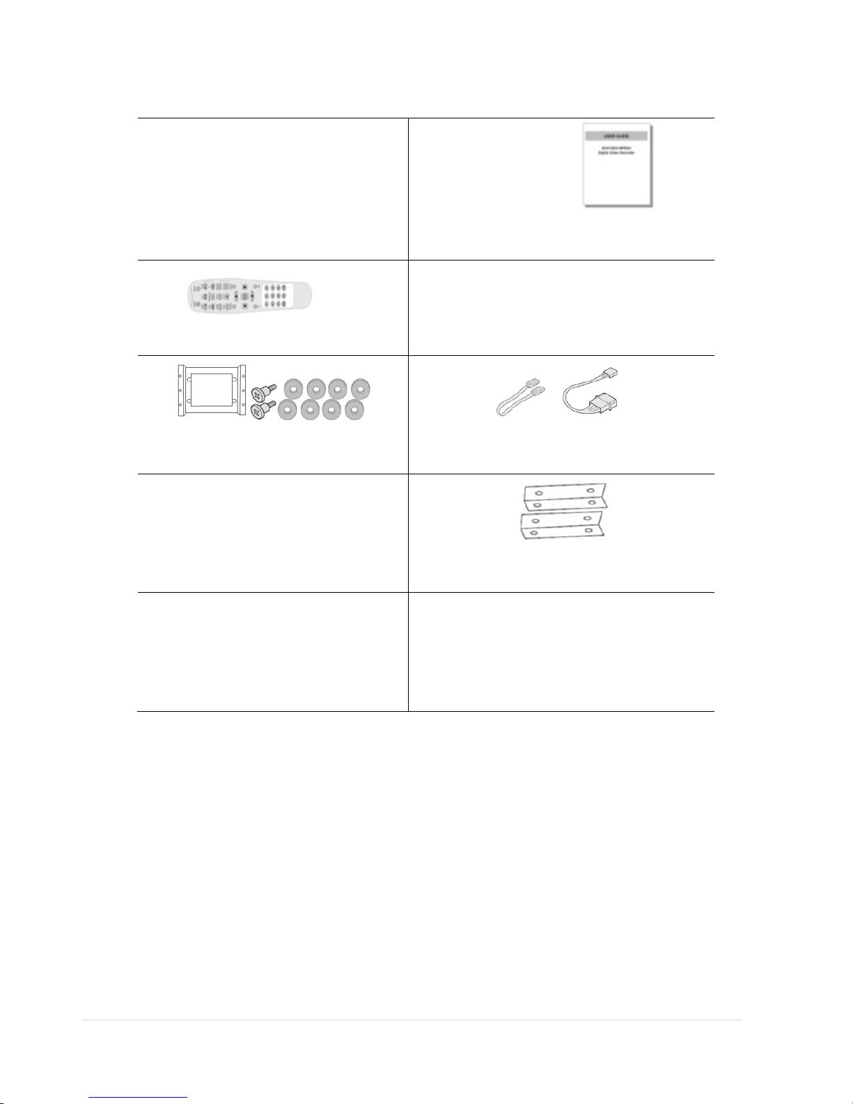
Product Components
Please make sure the following components are included as specified below.
DVR Set
Client Software CD, User
Guide
Remote Control , Battery1.5V
Mouse
HDD Mounting Bracket &
Screw*
SATA Cable, SATA Power Cable
HDD & DVD-RW Mounting
Screw
HDD & DVD-RW Mounting Bracket
Power Cable & Power Adapter
(1 EA)
Power Cable (1 EA)*
*For Real-time HD-SDI 8CH/16CH DVR only
Page 9

9 | Page
FEATURES
H.264 video compression
HDMI 1080P Video Output
Max. 1920 x 1080 Recording Resolution
QUADPLEX: Simultaneous live or playback while recording, network transfer, and backup
USB 2.0 port for backup, firmware upgrade, configuration export/import, or USB mouse
Individual channel operation such as FPS, quality, recording mode, & detection zone
Various network access: Network client SW, web-viewer, smart phone APP, and CMS
Remote setup and remote upgrade
Remote access via PC, MAC®, or smart phones
Recording by schedule, continuous, alarm, motion, or continuous
Free DDNS server
Bandwidth control
E-mail event notification
NTP (Network Time Protocol)
Watermark
Synchronized audio
Time stamp over backup data
Easy and various data backup via DVD, USB flash drive, USB external HDD, and network
HDD S.M.A.R.T status check and alert via e-mail or internal beep
USB mouse, IR remote control
Multi OSD languages
Made in Korea
Page 10
10 | Page
1. Name, Function and Connection
1-1. Front Panel
1-1-1. HD-SDI Real-time 4CH, HYBRID 8CH/16CH
The following information will help you to operate the front panel controls.
Figure 1.1.1. Front Panel
Indication Lights
NO. Name Description
A CH1~16 Indicates that the channel is being recorded.
B HDD Indicates that the system is accessing the hard disk.
C ALARM Indicates that sensor(s) is/are triggered or motion is detected.
D NETWORK Indicates that a network client is connected
E BACKUP Indicates that a USB or DVD-RW device contains stored data
F POWER Indicating that the system is powered on.
Front Panel Buttons
NO Name Description
1
Channel keys. For channel 10, press the 0 key. For channel 11,
press the +10 and 1 key. For channel 16, press the +10 and 6
key.
2
In playback mode, press to rewind the recording.
3
Press to select an audio mode:
MUTE –Mute all 4 channels.
SINGLE- Highlighted channel only.
MIX- Mix all 4 channels.
4
Jump/step backward. In playback mode, the playback position
moves 60 seconds backward.
Page 11

11 | Page
5
In playback mode, press to fast forward the recording.
6
Press to enable/disable ALARM operation.
7
Jump/step forward. In playback mode, the playback position
moves 60 seconds forward.
8
Press to start or stop manual recording.
9
In live display mode, press to open the SEARCH menu.
10
In playback mode, press to play/pause the footage.
11
Press to open the SETUP menu.
12
Enable/disable the automatic sequence of display of channels
in full screen, quad, 9-split display mode.
13
Press to control Pan/Tilt/Zoom operations.
14
Press to capture video in jpeg format in live or playback mode.
15 (LEFT)
Press to move left or to change the values in Setup mode.
It is also used as the number 4 when entering password.
16 (UP)
Press to move up the menu in Setup mode.
It is also used as the number 1 when entering password.
17 (RIGHT)
Press to move right or to change the values in Setup mode.
It is also used as the number 2 when entering password.
18 (DOWN)
Press to move down the menu in Setup mode.
It is also used as the number 3 when entering password.
19
Press to select desired menu item or to store the setup value.
20
Press for temporary storage of the changed value or to return
to the previous menu screen.
21 USB Port
To archive still-image or video into a USB flash drive or upgrade
the firmware with USB flash drive.
22 OPEN/CLOSE To open and close the insert tray, press the button.
23 DVD Drive To save video, insert a CD-R/DVD-R.
Page 12

12 | Page
1-1-2. HD-SDI Real-time 8CH/16CH
The following information will help you to operate the front panel controls.
Figure 1.1.2. Front panel
Indication Lights
NO. Name Description
A
CH1~16
Indicating that the channel is being recorded.
B
HDD
Indicating that the system is accessing the hard disk.
C
RECORD
Indicating that the system is recording video data.
D
ALARM
Indicating that when sensor(s) is/are triggered or motion is detected.
E
NETWORK
Indicating that when Network client connects through the network.
F
BACKUP
Indicating that USB or DVD-RW storage device is stored images or video.
Front Panel Buttons
NO
Name
Description
1
POWER ON/ OFF
2
Channel keys. For channel 10, press the 0 key. For channel 11, press the +10 and 1
key. For channel 16, press the +10 and 6 key.
3
Press to rewind the footage in playback mode.
4
Press to select audio mode such as SINGLE, MIX and MUTE.
MUTE- All of 4 channels.
SINGLE- Highlighted channel only.
MIX- All of 4 channels.
4
Jump/Step backward. In playback mode, the playback position moves 60 seconds
backward.
Page 13

13 | Page
5
Press to fast forward the footage in playback mode.
6
Press to enable/disable ALARM operation.
6
Jump/Step forward. In playback mode, the pl
ayback position moves 60 seconds
forward.
7
Press to start or stop manual recording.
8
Press to go to SEARCH menu in live display mode.
8
Press to play/pause the footage in playback mode.
9
Enable/disable the automatic sequence of display of channels in full screen, quad, 9-
split display mode.
10
Press to control Pan/Tilt/Zoom operations.
11
Press to enter SETUP menu.
12
Press to capture video in jpeg format in live or playback mode.
13
◀(LEFT)
Press to move left or to change the values in Setup mode.
It is also used as the number 4 when entering password.
14
▲(UP)
Press to move up the menu in Setup mode.
It is also used as the number 1 when entering password.
15
▶(RIGHT)
Press to move right or to change the values in Setup mode.
It is also used as the number 2 when entering password.
16
▼(DOWN)
Press to move down the menu in Setup mode.
It is also used as the number 3 when entering password.
17
Press to select desired menu item or to store the setup value.
18
Press for temporary storage of the changed value or to return to the previous menu
screen.
20
DVD drive
To save video, insert a CD-R/DVD-R
21
USB Port
To archive still-image or video into a USB memory or upgrade firmwar
e with USB
memory stick, connect a USB memory to the USB terminal on the front panel.
Page 14
14 | Page
1-2. Rear Panel
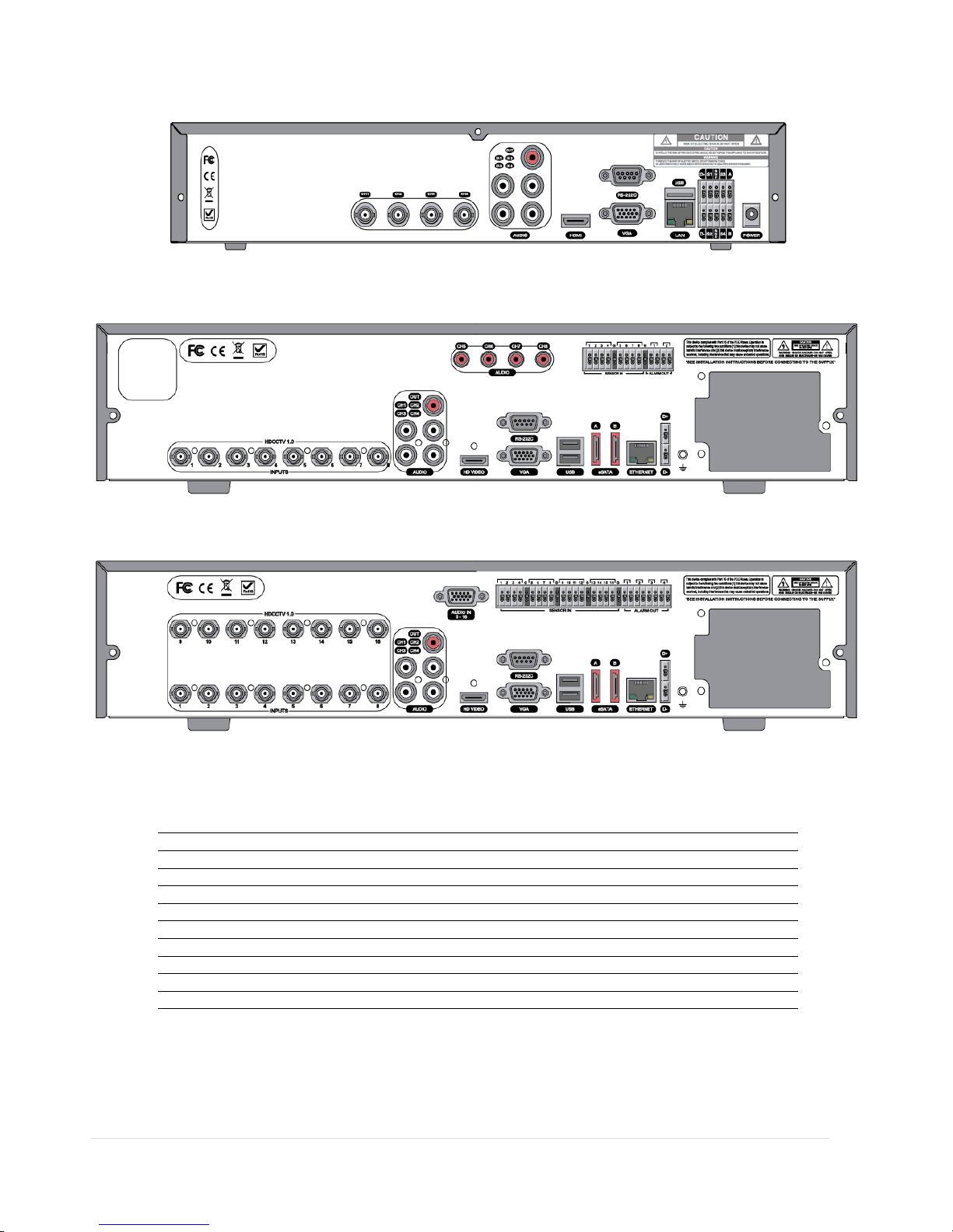
1-2-1. HD-SDI Real-time 4CH/8CH/16CH DVR
<4 Channels HD-SDI Real-time DV R >
<8Channels HD-SDI Real-time D VR>
<16 Channels HD-SDI Real-time D VR>
1
Cooling Fan
2
VIDEO
Video Input & Vid eo Output
3
AUDIO
Audio Input
4
HD VIDEO
HD VIDEO Output
5
RS-232C
RS 232 Terminal (For testing purposes)
6
VGA
VGA Output
7
eSATA
eSATA Port (8CH/16CH Only)
8
ETHERNET
Network RS-45 Ethern et Po rt
9
USB
USB Port
10
D+ D-
RS-485 PTZ Camera control terminal
11
SENSOR IN
Sensor input terminal
12
ALARM OUT
Alarm out terminal
Page 15
15 | Page
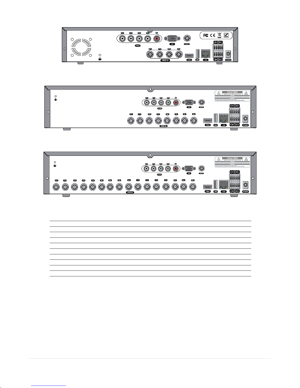
1-2-2. HYBRID 4CH/8CH/16CH DVR
<4 Channels Hybrid DVR>
<8 Channels Hybrid DVR>
<16 Channels Hybrid DVR>
1
Cooling Fan
2
VIDEO
Video Input & Vid eo Output
3
AUDIO
Audio Input
4
HD VIDEO
HD VIDEO Output
5
RS-232C
RS 232 Terminal (For testing purposes)
6
VGA
VGA Output
7
CVBS OUT
CVBS or SPOT Output
8
ETHERNET
Network RS-45 Ethern et Po rt
9
USB
USB Port
10
D+ D-
RS-485 PTZ Camera control terminal
11
SENSOR IN
Sensor input terminal
12
ALARM OUT
Alarm out terminal
Page 16

16 | Page
1-3. Remote Control
① ID: When a remote control ID number is set in the DVR, input the DVR ID number.
② REC: To start and stop manual recording.
③ Number: To select channel (1, 2, 3, & 4) or to enter DVR ID number.
④ F/REW: During playback - To move the playback position 60 seconds backward.
During pause - To move the playback position 1 frame backward.
⑤ F/ADV: During playback - To move the playback position 60 seconds forward.
During pause - To move the playback position moves 1 frame forward.
⑥ REW: To rewind the footage at 1x, 2x, and 4x speed during playback.
⑦ PLAY/PAUSE: To play or to pause the footage in playback mode.
⑧ FF: To fast forward the footage at 1x, 2x, and 4x speeds during playback.
⑨ Control button: Press to move the menu items or select channel.
⑩ SETUP: To launch SETUP menu.
⑪ SEARCH: To go to the search menu.
⑫ ESC: During setting - To return to previous menu screen.
During playback - To exit from playback
System Lock – To lock a system when pressing ESC button for 5 seconds.
System Unlock – To unlock a system when pressing ESC button for 5 seconds.
⑬ BACKUP: To start operations of backup in live or playback mode. (The same function button as CAPTURE on the
front panel of DVR)
⑭ SEQ: To start auto sequencing of the screen in full screen mode. (Toggle)
Page 17

17 | Page
2. Preparation
2-1. Booting the DVR and Basic Time Setting
1. During the first start up, the following message will be displayed.
2. After the system initializing is completed, select the language as specified below.
3. Set date and time as specified below.
Table 2.1.1. Menu Items in TIME ZONE & DAYLIGHT SAVING Setup Screen
Item Description
DAY LIGHT SAVING
Select DAYLIGHT SAVING using the mouse and the control button on the remote control and
select the appropriate daylight saving time zone.
If choosing EU or OTHERS, set the applicable conditions.
The options are:
OFF: Daylight saving is turned off.
USA: Applies the USA daylight saving time.
Page 18
18 | Page
EU: Applies the EU daylight saving time.
- Select the GMT AREA using the control button.
- Set the time difference with the standard time using the control button.
OTHERS: If the time zone is neither USA nor EU, set the start and end date of the daylight
saving period.
- Select BEGIN or END using the control button and press the SEL button.
- Select the item using the control button, select the setting value using the
control button
and press the ESC button to return to SET DATE & TIME setup
menu.
CAUTION:
- Do not set the start time to 23:00 for DLS.
- DLS can’t be applied if the date of BEGIN and END is the same.
Pacific Time Zone
• Los Angles, CA, USA : GMT - 8:00 for Standard time / GMT - 7:00 for Daylight time
Mountain Time Zone
• Denver, CO, USA : GMT - 6:00 for Standard time / GMT - 5:00 for Daylight time
Central Time Zone
• Chicago, IL, USA : GMT - 7:00 for Standard time / GMT - 6:00 for Daylight time
Eastern Time Zone
• Newyork, NY, USA : GMT - 5:00 for Standard time / GMT - 4:00 for Daylight time
State Standard Time Daylight-Saving Time
AL Alabama GMT-6 GMT-5
AK Alaska GMT-9 GMT-8
AK Alaska (Aleutian Islands) GMT-10
NA
AZ Arizona GMT-7
NA
AZ Arizona (Navajo) GMT-7 GMT-6
AR Arkansas GMT-6 GMT-5
CA California GMT-8 GMT-7
CO Colorado GMT-7 GMT-6
CT Connecticut GMT-5 GMT-4
DC District of Columbia GMT-5 GMT-4
DE Delaware GMT-5 GMT-4
FL Florida GMT-5 GMT-4
FL Florida (W) GMT-6 GMT-5
GA Georgia GMT-5 GMT-4
HI Hawaii GMT-10
NA
ID Idaho (N) GMT-8 GMT-7
ID Idaho (S) GMT-7 GMT-6
Page 19

19 | Page
IL Illinois GMT-6 GMT-5
IN Indiana GMT-5 GMT-4
IN Indiana (SW / NW) GMT-6 GMT-5
IA Iowa GMT-6 GMT-5
KS Kansas GMT-6 GMT-5
KS Kansas (W) GMT-7 GMT-6
KY Kentucky (E) GMT-5 GMT-4
KY Kentucky (W) GMT-6 GMT-5
LA Louisiana GMT-6 GMT-5
ME Maine GMT-5 GMT-4
MD Maryland GMT-5 GMT-4
MA Massachusetts GMT-5 GMT-4
MI Michigan GMT-5 GMT-4
MI Michigan (W) GMT-6 GMT-5
MN Minnesota GMT-6 GMT-5
MS Mississippi GMT-6 GMT-5
MO Missouri GMT-6 GMT-5
MT Montana GMT-7 GMT-6
NE Nebraska GMT-6 GMT-5
NE Nebraska (W) GMT-7 GMT-6
NV Nevada GMT-8 GMT-7
NH New Hampshire GMT-5 GMT-4
NJ New Jersey GMT-5 GMT-4
NM New Mexico GMT-7 GMT-6
NY New York GMT-5 GMT-4
NC North Carolina GMT-5 GMT-4
ND North Dakota GMT-6 GMT-5
ND North Dakota (W) GMT-7 GMT-6
OH Ohio GMT-5 GMT-4
OK Oklahoma GMT-6 GMT-5
OR Oregon GMT-8 GMT-7
OR Oregon (E) GMT-7 GMT-6
PA Pennsylvania GMT-5 GMT-4
RI Rhode Island GMT-5 GMT-4
SC South Carolina GMT-5 GMT-4
SD South Dakota (E) GMT-6 GMT-5
SD South Dakota (W) GMT-7 GMT-6
TN Tennessee (E) GMT-5 GMT-4
TN Tennessee (W) GMT-6 GMT-5
TX Texas GMT-6 GMT-5
Page 20

20 | Page
TX Texas (W) GMT-7 GMT-6
UT Utah GMT-7 GMT-6
VT Vermont GMT-5 GMT-4
VA Virginia GMT-5 GMT-4
WA Washington GMT-8 GMT-7
WV West Virginia GMT-5 GMT-4
WI Wisconsin GMT-6 GMT-5
WY Wyoming GMT-7 GMT-6
NOTE: If you want the unit to automatically synchronize the local time, the Time Zone must be
properly set according to your local Time Zone.
2-2. Setting NTP (Network Time Protocol)
1. When the DVR is connected with internet and the DVR need to be syncronized with NTP (Network Time
Protocol), set SETUP>SYSTEM>NTP ON.
2. Select proper TIME ZONE time.
Page 21

21 | Page
3. Setting up the DVR
The following sections detail the initial setup of the DVR.
3-1. Setup – Main screen
To enter the setup menu, right click on the mouse and select setup from the submenu or press the setup button on
the front panel or the remote control.
Figure 3.1.1. Setup Menu Tree
When the DVR prompts the LOG-IN window, enter the PASSWORD using the virtual keyboard, or the front panel, or
the remote control. The factory default password is 1111. It is highly recommended to assign a new password to
protect the system. User can assign a new password in SECURITY setup menu.
Page 22

22 | Page
3-2. Setup – Display Mode
In the SETUP menu, select the DISPLAY tab. Then, the DISPLAY menu is displayed as pictured below.
Figure 3.2.1. Display Mode Setup Screen
Table 3.2.1. Menu Items in DISPLAY Mode Setup
Item Description
OSD Enable/disable on-screen-display.
OSD CONTRAST Set the visibility level of the On Screen Display (OSD) (0~100)
SEQUENCE Enable/disable sequential display of video in full screen mode.
SEQ-DWELL
TIME
Set the dwell time of each, quad or 9 channels display in sequential display mode.
(3-60seconds)
CHANNEL Select a channel for applying the following settings using the mouse or control
button on the remote control. Press the right square button to change the setting
value of all channels at once.
Press SEL button to change the setting value of all
channels at once. Left click on the mouse to highlight the setting and double-click
if you want to change the value. Once the value has been changed, select OK to
confirm the changes.
(COVERT, BRIGHTNESS,CONTRAST,HUE,SATURATION)
NAME Set the channel name. The name can be made by 10 characters at most.
COVERT Enable/disable display of the specified video channel in live display mode.
BRIGHTNESS Change the brightness value of the specified channel. (0~100)
CONTRAST Change the contrast value of the specified channel. (0~100)
HUE Change the hue value of the specified channel. (0~100)
SATURATION Change the saturation value of the specified channel. (0~100)
Page 23

23 | Page
VIDEO OUTPUT
(HDMI/VGA)
Allows user to set monitor output resolution from
720p 50Hz/60Hz, 1080i
50Hz/60Hz, 1080p 50Hz/60Hz
3-3. Setup – Record Mode
In the SETUP menu, select the RECORD tab. Then, the RECORD menu is displayed as pictured below.
Figure 3.3.1. Recording Mode Setup Screen
Table 3.3.1. Menu Items in Recording Mode Setup
Menu Item Description
CHANNEL Select a channel for applying the following settings using the mouse or the
control button on the remote control. Press the right square button to change
the setting value of all channels at once. Once you the value has been changed,
select OK to confirm the changes.
(RESOLUTION, FRAME RATE, QUALITY, RECORDING, PRE RECORD and POST
EVENT RECORD)
RESOLUTION
• Analog DVR: Select either CIF, Half D1 and D1 using the mouse or the
control button on the remote control.
• HD-SDI DVR: Select either 640 x 360, 1280 x 720, 1920 x 1080 using the
mouse or the control button on the remote control.
FRAME RATE
Select the recording frame rate for the specified channel.
QUALITY
Select the recording quality for the specified channel. LEVEL 1 ~ 5 (Allows
the user to change the recording QUALITY of the selected CHANNEL)
Page 24

24 | Page
RECORDING
Assign the recording mode for each channel. Options are: Continuous, By
Motion, By Sensor, By Schedule or Disable.
SENSOR RECORDING Enable setting up to 4 sensors for the specified channel using the mouse or the
control button of the remote control.
PRE RECORD Enable/disable pre-event recording. Pre-event recording time is 5 seconds to 20
Minutes.
POST EVENT RECORD Set the post event recording time duration for the specified channel. (10~60
seconds)
AUDIO Enable/disable audio recording for the specified channel.
SCHEDULE Set the recording schedule. Press SEL to enter the schedule setup screen.
3-3-1. Recording Schedules
To setup a recording schedule, select SCHEDULE in the RECORD menu.
[Channel]: Select the specific channel.
[Setup]: Set up using the left button of the mouse to section under the specific day and time. It can set the all section
under the specific day or time at a time when pressing the specific day or time. It is also possible to set up
recording modes of various type using a CONTINUOUS (green), Motion (yellow) and Sensor (red). Left-Click
and drag the mouse to change the schedule for more than one timeslot.
[COPY Schedule]: To copy the schedule setup from one channel to another, select the channel to copy using the
mouse or the buttons on the remote control, and select to channel to copy to and press the select button. Select
OK to confirm the changes.
Figure 3.3.2. Schedule Recording Setup Screen
Page 25

25 | Page
3-4. Setup – Device Mode
In the SETUP menu, select the DEVICE tab. Then, the device menu is displayed as pictured below.
Figure 3.4.1. Device Mode Setup Screen
Table 3.4.1. Menu Items in Device Setup Screen
Item Description
ALARM OUT Set the sensor, motion, and video loss for each alarm.
CONTROLLER & PTZ Set the PTZ baud rate, protocol, and ID.
SPOT-OUT Set the all details for spot monitoring. It supports 2 spot-outs.
CHANNEL Select specified channel for motion zone setup.
MOTION ZONE Select either Full Zone or Partial Zone for motion sensing.
MOTION SENSITIVITY Set the motion sensitivity for the specified channel.
Control the motion sensitivity from 1 to 9.
PRIVACY ZONE Set the privacy zone for the specified channel.
KEY TONE Enable/disable key tone.
REMOTE CONTROL ID Select an ID of remote control.
1. Select ID number.
2. Press the same number as ID set in DVR on the remote control.
3. An icon will be displayed on the Liv
e Screen that corresponds to the
remote control ID number.0
The options are from 0 to 99
SENSOR Select sensor NO from 1 to 4
TYPE Set the type of sensor for the specified channel. Options are: OFF
, N/O
(normal open), and N/C (normal closed).
Page 26

26 | Page
VIDEO INPUT
TRIMMING
When the resolution of input video is less than 960x480 such as 940x480, the
right and left part in black can be trimmed.
3-4-1. ALARM-OUT
Figure 3.4.2. ALARM-OUT Setup Screen
Table 3.4.2. Menu Item in ALARM-OUT Setup Screen
Item Description
ALARM OUT Select an Alarm out number.
ALARM DURATION Set the alarm dwell time from 5 to 60 seconds.
3-4-2 SPOT-OUT Setup
Figure 3.4.3. SPOT-OUT Setup Screen
Page 27

27 | Page
Table 3.4.3. Menu item in SPOT-OUT Setup Screen
Item Description
SPOT ON EVENT Enable/Disable display of the channel when an event is active.
SPOT EVENT
DWELL TIME
Set the dwell time for the display of the event activated channel. (1-10sec)
SEQUENCE Enable/disable sequential display of spot channel in full screen.
If select ON, spot channel selection screen is displayed.
SEQ-DWEL TIME Set the dwell time for the spot channel display.(1-10sec)
SP’OT CHANNEL Select a channel for spot monitoring using the mouse or the control button on
the remote control and press OK button.
3-4-3. CONTROLLER & PTZ Setup
To control the PTZ functions of the camera, connect a controller to the RS-485 port.
① Connect the RS-485 cables of the PTZ camera to the RS-485 port on the rear panel.
② Press the PTZ menu button. Then PTZ menu screen is displayed as below.
Figure 3.4.4. CONTROLLER & PTZ Control Setup Screen
Page 28

28 | Page
Table 3.4.4. Menu item in CONTROLLER Setup Screen
Item Description
CONTROLLER Select the controller model.
SPEED Select the speed (Baud Rate) of the controller.
ID Select the controller ID.
Table 3.4.5. Menu item in PTZ Setup Screen
Item Description
CHANNEL Select the channel that the PTZ camera is connected.
CAMERA Select the protocol of the camera.
SPEED Select the speed (Baud Rate) of the camera.
ID Select the camera ID.
Note: For speed dome cameras that support RS-485, connect them directly to the RS-485 port. If the camera is
controlled with RS-232C, use a RS-485 to RS-232C signal converter.
3-4-4. Motion Zone Setup
Select MOTION ZONE using the mouse or the control button on the remote control and select either PARTIAL ZONE
or FULL ZONE using the mouse control. The default value is FULL ZONE.
If FULL ZONE is selected, the motion zone grid screen is not displayed. Only set the level of sensitivity for MOTION
SENSITIVITY.
FULL ZONE: The motion sensor is active on the whole screen.
PARTIAL ZONE: The motion sensor is active in the set detection frame.
Select the motion detection region and select the motion detection position using the mouse or the control button
on the remote control. Then left click on the mouse or left click and drag the mouse pointer to select or deselect the
area. Highlighted area indicates the partial motion detection zone. Press the ESC button or right click on the mouse to
return to the previous menu.
Page 29

29 | Page
Figure 3.4.5. Motion Zone Grid Screen
3-4-5. Privacy Zone Setup
Select PRIVACY ZONE using the mouse or the control button on the remote control.
Select the motion detection position using the mouse or the control button on the remote control. Then left click on
the mouse or left click and drag the mouse pointer to select or deselect the area. Highlighted area indicates the
partial motion detection zone. Press the ESC button or right click on the mouse to return to the previous menu.
Figure 3.4.6. Privacy Zone Grid Screen
Page 30

30 | Page
3-5. Setup – Storage Mode
In the SETUP menu, select the STORAGE tab. Then, the STORAGE menu is displayed as pictured below.
Figure 3.5.1. STORAGE Setup Screen
Table 3.5.1. Menu Items in STORAGE Setup Screen
Item Description
OVERWRITE When enabled, the DVR will continue recording and overwrite the oldest
existing recorded data once the hard drive is full. When disabled, recording
will stop once the hard drive is full.
DIS K FORM AT You will have an option YES or NO for the hard drive format.
Caution:
We recommend that you archive any data that you may need in the future
before you format the hard drive.
DISK INFO Hard drive information.
RECORDING LIMIT Enable/disable recording limit.
RECORDING LIMIT DAYS Set the recording limit days. (1- 90 days)
When setting to 1 day, the data will be removed by the hour.
Page 31

31 | Page
3-5-1. DISK FORMAT
Figure 3.5.2. DI SK FORMAT Screen
Note: If you format the HDD, all recorded data can not be searched.
3-5-2. DISK INFO
Figure 3.5.2. DISK INFO Screen
Click
button in order to see the detailed information of the HDD.
Page 32

32 | Page
Figure 3.5.3. DETAILS of DISK INFO Screen
Click
button in order to see the explanations of detailed information of the HDD.
Figure 3.5.3. EXPLANATION of DETAILED DISK INFO Screen
Note: If the HDD has any bad sector that mention as above, please change with a new HDD.
Page 33

33 | Page
3-6. Setup – System Mode
In the SETUP menu, select the SYSTEM tab. Then, the SYSTEM menu is displayed as pictured below.
Figure 3.6.1. SYSTEM Setup Screen
Table 3.6.1. Menu Items in SYSTEM Setup Screen
Item Description
DVR ID Set DVR ID using the mouse or the control button on the remote control. Press OK to apply the DVR
ID.
DESCRIPTION Press the button to view the system information.
Hardware version, Software version, Storage size, IP address, MAC address and DDNS status and Port
Forward Status.
LANGUAGE Select the display language using the mouse or the control button on the remote control. Once a
language is selected, the display language changes.
DAT E
FO RMAT
Select the date display format using the mouse or the control button on the remote control. Options
are:
(YYYY/MM/DD, MM/DD/YYYY, DD/MM/YYYY, YYYY-MM-DD, MM-DD-YYYY, DD-MM-YYYY)
SET
DATE&TIME
Select the display date and time using the mouse or the control button on the remote control and
press OK button to set the present date and time.
DAY LIG HT
Select DAYLIGHT SAVING using the mouse and the control button on the remote control and select
Page 34

34 | Page
SAVING
the appropriate daylight saving time zone.
If choosing EU or OTHERS, set the applicable conditions.
The options are:
OFF: Daylight saving is turned off.
USA: Applies the USA daylight saving time.
EU: Applies the EU daylight saving time.
- Select the GMT AREA using the control button.
- Set the time difference with the standard time using the control button.
OTHERS: If the time zone is neither USA nor EU, set the start and end date of the daylight saving
period.
- Select BEGIN or END using the control button and press the SEL button.
- Select
the item using the control button, select the setting value using the control
button and press the ESC button to return to SET DATE & TIME setup menu.
CAUTION:
- Do not set the start time to 23:00 for DLS.
- DLS can’t be applied if the date of BEGIN and END is the same.
CLIENT
ACCESS
Enable/Disable remote access through network client software.
NTP NTP is an abbreviation for Network Time Protocol, which is for synchronizing the time of the
computer systems over variable-latency data networks.
PRIMARY SNTP SERVER: Input the address of the primary NTP time server.
SECONDARY SNTP SERVER: Input the address of the secondary NTP time server.
TIME ZONE: Greenwich Mean Time (GMT) is a term originally referring to mean solar time at the
Royal Observatory, Greenwich, London. Because NTP synchronizes with Greenwich Mean Time
(GMT) regardless of geography, users must set their own time difference.
CONNECTON MODE: Select NTP time server connection mode.
INTERVAL: Synchronize the clock by hours which is set on the connection period menu.
TIME: Synchronize the clock at the time daily which is set on the connection period menu.
CONNECTION PERIOD: 1~24
Page 35

35 | Page
SEND EMAIL
TRANSMISSION MODE: Select e-mail attachment format as an image or a video clip of the channel
that triggered the alarm when an alarm event is triggered.
IP NOTIFICATION: Enable/disable sending e-mail when the IP address of your DVR is changed.
EVENT ALARM: Enable/disable sending e-
mail reports on the channel that triggered the alarm when
an alarm event is triggered.
S.M.A.R.T: Allows the user to set S.M.A.R.T NOTIFICATION ON or OFF
MAIL PORT: Allows the user to set E-MAIL PORT
SECURE OPTION: – NONE, SSL, TLS (Allows the user to select E-MAIL SECURE OPTION)
MAIL TO: Enter the appropriate email address to enable sending e-
mail reports using a virtual
keyboard.
MAIL SERVER: Enter the appropriate mail server information to enable sending daily e-mail reports
using a virtual keyboard.
ID: To set the connection user ID for the mail server using a virtual keyboard.
(ex.abcd@abcdefg.com)
PAS SWORD: To set the connection password for the mail server using a virtual keyboard.
MAIL FROM: To set the mail address sent to the destination host using a virtual keyboard.
Page 36

36 | Page
3-7. Setup – Security Mode
In the SETUP menu, select the SECURITY tab. Then, the SECURITY menu is displayed as pictured be lo w. Navigate
through the menu items using the mouse or the control button on the remote control and change the value of the
menu item.
Figure 3.7.1. SECURITY Setup Screen
Table 3.7.1. Menu Items in PASSWRORD Setup Screen
Item Description
USER
AUTHENTICATION
Admin only can access to the menu.
PASSWORD CHECK:
Select either V or nothing for the functions such as
SETUP, PB (Playback), PTZ, REC OFF(Record OFF), and NETWORK
Selected Checkbox: The DVR will ask for a password when the given function is selected
for all users.
Blank Checkbox: The DVR will not ask for a password when the given function is selected
for all users.
ADMIN, NETOWRK, USER1, USER2, USER3:
Selected Checkbox: The user can access to the function.
Page 37

37 | Page
Blank Checkbox: The user can not access to the function.
USER NAME
User name can be changed.
USER PASSWORD
Options are ADMIN, NETWORK, USER1, USER2 and USER3.
Select USER PASSWORD using the mouse o
r the control button on the remote control
and press SEL button. Select user type and enter the current password. And, enter a
new password, enter the same password again to confirm and select OK. Then the
message “PASSWORD CHANGED” is displayed.
The factory default password is 1111.
PLAYBACK AUTHORITY
Allows specific users AUTHORITY OF PLAYBACK per CHANNEL
NETWORK LIVE
AUTHORITY
Allows specific users AUTHORITY OF LIVE per CHANNEL
Page 38

38 | Page
When the user set this function, the login window will appear. Then, the user can select one of user types (ADMIN,
USER1, USER2, USER3) using the mouse or the control button on the remote control. The user can select a password
using the mouse or the control button on the remote control.
The factory default password is 1111. It is highly recommended to assign a new password to protect the system.
User can assign a new password in the SECURITY setup menu.
3-8. Setup – Network Mode
In the SETUP menu, select the NETWORK tab. Then, the network menu is displayed as pictured below.
Figure 3.8.1. NETWORK Setup Screen
Table 3.8.1. Menu Items in Network Setup Screen
Item Description
NETWORK
PORT
Set a proper port number for connecting to network. Port number (Default: 5445)
NETWORK
AUDIO
PORT
Port for audio streaming: NETWORK PORT + 1
WEB PORT Web Sever Port number (Default: 80)
NETWORK
TYPE
Select a type of network connection. Options are:
STATIC, DHCP
DHCP: DVR will automatically retrieve an IP address from the network.
LAN: Network information must be manually configured.
DHCP DVR will automatically retrieve an IP address from the network.
LAN IP: Register IP address that is assigned for the DVR.
Page 39

39 | Page
Gateway: Register Gateway that is assigned for the DVR.
Subnet Mask: Register Subnet Mask that is assigned for the DVR.
DDNS Enable/disable using domain name address through DDNS server and select the type of DDNS services
according to the DVR model.
SERVER1: to use Type 1 free DDNS that is serviced by the manufacturer.
SERVER2: to use other general-purpose DDNS Server, such as ‘dyndns.org’.
NETWORK
STREAM
Set the value for network streaming.
WIRELESS
LAN
The DVR can be linked using USB Wifi Dongle.
1. Connect USB Wifi Dongle to USB connector on DVR.
2. Load the application on your smart phone or PC and enter the WIFI IP ADDRESS.
3. Find the WIFI SSID and enter the password. (shown in image below)
4. Then, the remote viewing and configuration can be used.
* There is a distance limitation for the Wireless LAN.
Page 40

40 | Page
3-8-1. DDNS
3-8-1-1. DDNS Connection with SERVER1 (setddns.com)
Free DDNS service for Dynamic IP users is provided. Please follow the instruction if your public
IP address is a dynamic IP.
1. Select DDNS as SERVER1 and click button. Then the DDNS menu will display.
• Automatic Host name registration: Click button. Then the MAC Address of DVR will
be registered automatically as a host name on DDNS.
• Manual Host name registration: Click button. Then the keyboard window will display.
2. Click OK and save the configuration.
3. Check the status of the DDNS registration on the popup window.
Page 41

41 | Page
3-8-1-3. DDNS Connection with SERVER2 (3rd Party DDNS)
If you want to use other third party DDNS like “dyndns.org”, please follow the instruction.
1. Select DDNS as SERVER2 and click button. Then the DDNS menu will display.
2. Enter the ID and Password of the 3
rd
party DDNS.
3. Click button. Then the keyboard window will display. Then, input DDNS SERVER NAME, DDNS
IP, and DDNS PASSWORD.
4. Click OK and save the configuration.
5. Check the status of the DDNS registration on the popup window.
6. Run network client software and add a site.
Page 42

42 | Page
3-8-2. Network Ports
When you connect one or more DVRs to a network through an IP sharing device, each device must have a unique TCP
port number for access to each unit from outside the LAN. The IP sharing device must be configured to forward the
assigned port to the specific DVR.
Note: This port number is listed next to the Port menu option in the Network Setup screen. If you plan to access the
DVR units only from within the same LAN, the TCP port does not have to be changed.
3-8-3. Network Stre am
User can set the frame rate and the bit rate for a network stream for a specific channel.
<Note> The network streaming is possible to set up to the recording frame rate of the channel.
Figure 3.8.4. Network Setup Screen – Network Stream
Network Access Beyond a Router
In order to access the DVR remotely beyond a router (firewall), the user must open TCP port
for command level, live channels and storage channels. The user needs to open 3 ports on
the router; the DVR port 5445, 5446, and the WEB port 80.
If this port is not opened properly, the user can not access DVR beyond a router.
Page 43

43 | Page
3-9. Setup - CONFIG Mode
In the SETUP menu, select the CONFIG tab. Then, the configuration menu is displayed as pictured below. Navigate
through the menu items using the mouse or the control button on the remote control and change the value of the
menu item.
Figure 3.9.1. Configuration Setup Screen
Table 3.9.1. Configuration Setup
Item Description
SAVE SETUP TO
A USB
User can save the current configuration (Setting values) of the DVR to the USB flash
drive. Plug in the USB flash on the front panel and press the button to start the
saving process.
LOAD SETUP
FROM A USB
User can upload the configuration of the DVR to another DVR using the USB
Flash drive. Plug in the USB flash drive on the front panel and press the button to
start the loading process.
Page 44

44 | Page
LO AD DEFAULT Press the button to reset the system to the default settings.
(The following settings such as Language, DVR ID, Security User Authentication,
Security User P/W, Date format, DLS settings, Network
settings, HDD overwrite,
Limit recording, HDD serial number, and HDD ERROR time will not be included.)
LOAD FACTORY
DEFAULT
Press the button to reset the system to the factory default settings.
SOFTWARE
UPGRADE
Upgrade softeware to the latest version.
After connecting USB flash drive to USB port on the DVR, click SEARCH.
It will automatically find the upgrade file.
Page 45

45 | Page
3-10. Quick Setup
In the MENU, select the QUICK SETUP tab. Then, the QUICK SETUP menu is displayed as pictured below. Navigate
through the menu items using the mouse or the control button on the remote control and change the value of the
menu item.
The QUICK SETUP has high priority than other setting values on RECORDING and NETWORK menu. The QUICK SETUP
also cannot set to classified according to channel.
Figure 3.10.1. Quick Setup Screen
Table 3.10.1. Quick Setup
Item Description
USE QUICK
SETUP
Select the Checkbox to use the Quick Setup.
When user inputs the DESIRED DAYS to record, the system displays a recommended
resolution, frame rate, quality and recording type after calculating the capacity of
the installed HDD. At that time, the priority is followed by the order of the items;
resolution, frame rate, quality and recording type.
CUSTOMER
SETTINGS
User can change the setting value such as resolution, frame rate, quality and
recording type. By the setting value, the DAYS TO RECORD will change.
Page 46

46 | Page
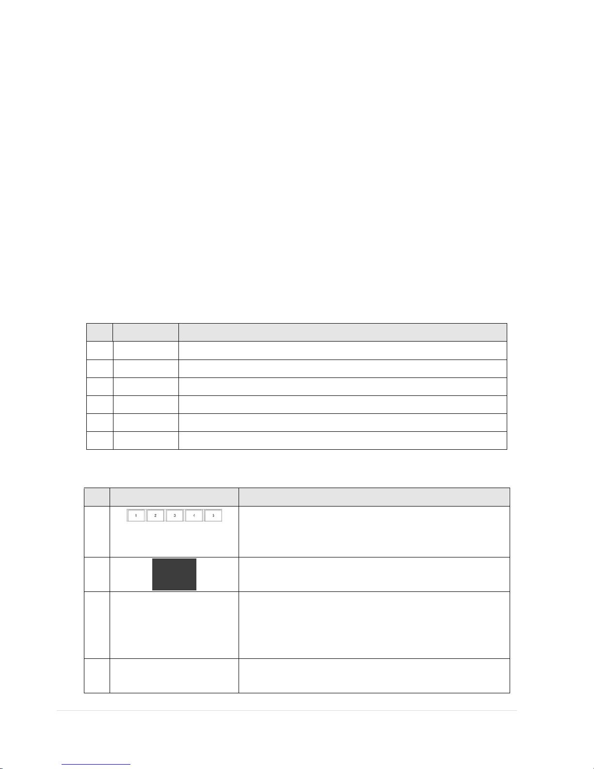
4. Live, Search and Playback
4-1. Live Viewing Screen
In the Live screen, video inputs from the cameras are displayed as they are configured in the Display Setup screen.
Various On-Screen Display (OSD) symbols, which indicate the status of the DVR, are described in Table 4.1.1.
Figure 4.1.1. Live Viewing Screen
Table 4.1.1. Status Indicator Icons in Live Viewing Screen
Icon Description
Power On/Off button.
Lock/Unlock Setup button.
Setup button. Click this button to go to a setup menu.
Audio button. Click
this button to set an audio reception type; Audio Mute, 1
channel or 4 channels. To set just 1 channel, select a specific channel on the live
screen at first.
Search button. Click this button to enter the search menu.
Backup button. Click this button to do a back-up.
PTZ button. Opens the PTZ control menu.
Page 47

47 | Page
Sequence button. Click this button to use a sequence function.
Manual Record button. Click this button to enable manual recording.
Alarm-out function On/Off button. Select this button to disable the alarm.
Click the split screen icon to change the current split screen mode using the mouse
or SEL button.
Displays the current date and time.
Remote control ID display. If a remote ID is not set, the message “A(all)” is
displayed.
Displays the amount of recording on the hard disk from 0-99%.
Indicates that HDD is recycled.
Continuous recording in progress.
Manual recording in progress. To set the Manual recording mode, press the Record
button on the front panel.
Motion alarm recording in progress.
Sensor recording in progress.
Indicates that the lock is set.
Audio mute. To set audio mute, press the Audio button on the front panel.
Single audio display. To set audio single for highlighted channel only, press the
Audio button on the front panel.
To mix audio display, press the Audio button on the left side.
Indicates that alarm is set. To set the alarm function, press the Alarm button on the
front panel.
Indicates that alarm output is activated.
Event indicator. When there is an event (motion recording, video loss, HDD fail,
S.M.A.R.T), this icon will be highlighted bright.
Indicates that a network client is connected to the DVR.
Indicates that sequencing mode is enabled.
Page 48

48 | Page
4-2. SEARCH Screen
To enter the search screen menu, select SEARCH menu on the screen using the mouse or press SEARCH icon on live
screen.
Figure 4.2.1. Search Screen
There are 7 ways of search menu such as TIMELINE, EVENT, GO TO FIRST TIME, GO TO LAST TIME, GO TO SPECIFIC
TIME, ARCHIVE and LOG on the screen.
4-2-1. TIME-LINE Search
The TIME-LINE search window is used to find the stored video by using the time line bar.
Page 49

49 | Page
When the Timeline menu is selected, the user can see a calendar which has the recorded data. Select a specific date
and time. Use a drag-and-drop function of the mouse control. User can select a specific minutes using a button in the
above red box. Press the PLAY button after selecting the specific time. Press the PREV to return to the SEARCH
window.
4-2-2. Event Search
The Event Search window is used to find stored video.
Figure 4.2.2. Event Search Screen
Page 50

50 | Page
When the Event menu is selected, the user can see a calendar which has recorded data. Select a specific date and the
event log will be displayed. Press the PLAY button to playback the data or the SAVE button to save the data after
selecting the specific data. User can find a data of the specific channel and event using a button in the above red box.
Press the PREV to return to the SEARCH windo w.
4-2-3. Go To First Time
You can access from the oldest recorded data on the DVR hard drive by selecting GO TO FIRST TIME on the
SEARCH window. Press the PREV to return to the SEARCH window.
4-2-4. Go To Last Time
You can access from the last minute recorded data on the DVR hard drive by selecting GO TO LAST TME on the
SEARCH window. Press the PREV to return to the SEARCH window.
4-2-5. Go T o S p ecif ic Time
Figure 4.2.3. Go To Specific Time
User can search for video data from a specific instance by setting the date and time in the Go To Specific Time
menu. Use the mouse or the control button on the remote control to change the date and time value and press
the PLAY button after setting. If there are not video data in the set date and time, No Data Exist message displays.
Page 51

51 | Page
4-2-6. Archive Search
The ARCHIVE Search window is used to find previously stored video or images.
Figure 4.2.4. Archive Search Screen
When the Archive menu is selected, the user can see a calendar which has recording data. Select a specific date and
then the archived data will be displayed. Press the Display button to view the still image or the first frame of the
selected video, then the user can save the selected data.
4-2-7. Log Search
You can access the LOG list search screen by selecting LOG on the SEARCH window.
Page 52

52 | Page
Figure 4.2.5. Log Search Screen
When the Log menu is selected, the user can see a calendar which has recording data. Select a specific date and
press NEXT button, and then the log data will be displayed. Press the SAVE button to save the data and then the data
is saved as a text file format.
4-3. Play Mode
During playback of a recorded event, the mode changes from SEARCH to PLAY. While in PLAY mode, you may return
to the SEARCH screen by pressing the X button on the status bar or the ESC button of a remote control.
Figure 4.3.1. PLAY Mode Screen
Page 53

53 | Page
The following status bar hides automatically and appears again when putting a mouse pointer to the bar.
Table 4.3.1. Button Functions in PLAY Mode
Button Description
Return to the previous menu screen, search window, or exit from the
Menu.
◀◀
Press to rewind the footage at 1x, 2x and 4x speeds. Reverse playback speed
is shown as -1x(normal), -2x (2 times normal) and -4x (4 times normal) at the
bottom right of the screen.
--◀
Jump/Step backward.
The playback position moves 60 seconds backward.
▶
/ II
Press to play or pause recorded video.
▶
--
Jump/Step forward. Playback position moves 60 seconds forward.
▶▶
Press to fast forward the footage at 1x, 2x and 4x speeds. Playback speed is
indicated as +1x, +2x and +4x for normal, twice and 4 times of the regular
speed at the bottom right of the screen.
Press to backup the video.
Page 54

54 | Page
5. PTZ Control
To control the PTZ functions of the camera, select PTZ menu on the screen using the mouse. Select the item you
wish to control the PTZ camera and control them using the mouse or the control button on the remote control.
Please refer to the table 5.1. for the control.
Figure 5.1. PTZ
Control Screen
Table 5.1. Button Functions in PTZ Control
Item Description
INITIALIZE Initialize the PTZ settings of the selected camera.
PAN / TILT
Select PAN/TILT
using the mouse or the control button and press SEL
button on the remote control.
Adjust the tilt (UP/DOWN) / pan
(LEFT/RIGHT) position using the
mouse or the control button on the remote control.
ZOOM /
FOCUS
Select ZOOM/FOCUS using the mouse or the control button and press
SEL button on the remote control.
Adjust the zoom (Mouse Wheel Down
or Up/Down button of the
remote control)/focus
(Mouse Wheel Up or Left/Right button of the
remote control) position.
OSD
Select the OSD to enter the menu. Control keys are Right, Left, UP,
Down, Select, Far (REW KEY), and Near (FF KEY). Press the ESC button
to return to the main menu. Press the PTZ button to escape from the
OSD menu.
AUTOSCAN
Press the right key (▶) on the control button to start auto scan
Press the left key (◀) on the control button to stop auto scan.
PRESET
Select the PRESET and press the left key (◀)
on the control button.
Then, number input window will appear. Set the number (3 digits)
using t
he number key and press the SEL to set the preset number for
the current position.
Press the right key (▶)
on the control button and set the number (3
digits) to go to the preset number.
TOUR
Select the TOUR and press the right key (▶) on the control button.
Then, number input window will appear. Set the number (1 digit) using
the number key and press SEL to make the group number work.
Press the left key (◀) on the control button to stop tour.
User can set the preset number in the tour group of the OSD menu.
NUMBER
Available only on the TOUR and PRESET menu.
Press the ESC button to return to the main menu.
Page 55

55 | Page
6. Back Up
6-1. Backup
Still images and videos can be captured and archived onto a media such as USB flash drive, a USB hard drive, or DVD
(if DVD burner is installed.).
1. When you press
BACKUP button on the playback screen, the archiving screen will display as Figure
6.1.1.
2. Once you press Backup button, the system will start to archive the data to the selected media.
Page 56

56 | Page
Table 6.1.1. Type of Backup
Item Description
STILL IMAGE JPEG image is archived and backup on the media.
NSF The backup video will be archived on the media as a proprietary format that can
only be playback from the HDPLAYER, an exclusive player.
AVI-SUBTITLE The backup video that the time data is integrated on will be archived on the media
as a AVI format.
AVI-SEPARATED
SUBTITLE
The backup video will be archived on the media as a AVI format, along with time
data subtitle. This backup format can be playback from a MAC.
NOTICE For a backup using a USB Flash Drive, the file format of the USB flash drive has to be FAT32.
Page 57

57 | Page
6-4. Playback of Backup Video
AVI format: AVI format video can be played back using Window Media Player™ or other media player that is
compatible with AVI format video.
NSF format: H.264 format video can be played back using the player (the HD player) that the DVR copies on USB flash
drive with video. This format is only available when the user selects a huge backup.
1. Insert a USB flash drive in the USB port on the PC.
2. Run HDPlayer in ‘DvrPlayer’ folder.
3. Click Button to search the backup video clip.
Page 58

58 | Page
4. Select the target folder that has backup video clip. Then the player will play the
video.
Page 59

59 | Page
7. Single Site Network Viewer
The DVR provides a live remote monitoring feature. Remote monitoring requires installation of the network viewer
on your PC.
NOTICE
In a high bandwidth network, a maximum of four users can access one DVR simultaneously. In a low
bandwidth network it is recommended that only one user access the DVR at a time.
7-1. PC Requirements
Minimum PC Requirements
• CPU: Intel® Pentium® IV, 1.4 GHz or higher
• Memory: 512MB (1GB or larger is recommended.)
• VGA memory: 16 MB (64 MB or larger is recommended.)
• Resolution: 1024 x 768
• Supported operating systems: Microsoft® Windows® 2000, Windows XP Professional, Windows XP Home, Windows 7
• DirectX®: DirectX 8.1 or higher
7-2. Installing the Network Viewer
1. Insert the provided CD in the CD drive and double-click “UMSClient(XXXX).exe”
2. Select a destination folder and click “Next”.
3. Select the program folder and click “Next”.
Page 60

60 | Page
4. The setup status screen is displayed.
5. After the installation is completed, “UMS Client” icon displays on the desktop screen.
Page 61

61 | Page
7-3. Live Monitoring Mode and Functions.
Button Function Description
DATE & TIME Displays the current date and time.
CONNECT/DISCONNECT Connect/disconnect network connection.
SEARCH Switches the live mode to search mode.
DISPLAY MODE Select a channel and screen display mode.
PAN/TILT/ZOOM/
FOCUS
Control the PAN/TILT/ZOOM/FOCUS
features on the remote camera.
CAPTURE Capture a still image from the live screen.
Page 62

62 | Page
PLAY/PA USE Play/pause live video.
ALARM The ON/OFF button of the alarm output of
the DVR. If the DVR has an alarm output,
the button will be indicated red.
SETUP
Display the setup screen of the network
viewer.
HDD USAGE DVR HDD storage Indicator.
NETWORK
BANDWIDTH
Shows the transferred frames and network
bandwidth.
AUDIO Adjust the volume. The audio can be turned
on or off by clicking the audio icon.
LOG WINDOW Shows the even log, date, and time.
Image capture of live screen
Still-image of live screen can be captured and saved as a BMP or JPEG file.
1. Click the channel to be captured. Then the selected channel will be highlighted red.
2. Click the CAPTURE button. Then the IMAGE CAPTURE dialog is displayed.
3. Set the SAVE PATH, FILE NAME, and FILE FORMAT and click the OK button to save the captured still image.
7-4. Bi-directional Audio
The UMS Client allows for bi-directional audio between the client and the DVR unit. The DVR must have an audio
input connected, and the PC must have an audio output.
Page 63

63 | Page
7-5. Remote Search Mode and Functions
Button Function Description
DATE & TIME
Displays the recording time of the data selected
on the time bar at the bottom of the main user
interface.
DISCONNECT Disconnect network connection.
LIVE Switches the search mode to live mode.
CAPTURE Capture a still image from live screen.
MARK IN Set the start time for video backup.
MARK OUT Set the ending time for video backup.
BACKUP
Backup the selected recorded video as AVI
format.
Page 64

64 | Page
SEARCH CALENDAR The calendar shows dates with recorded video in
a light blue and the selected date in dark blue.
TIMELINE BAR The timeline shows recorded data in dark blue on
the bar.
PLAYBACK BUTTON The playback buttons.
DISPLAY MODE Select a channel and screen display mode.
Searching and playing video in the remote DVR
Video recorded in the remote DVR or Video recorded on the PC can be searched and played back.
1. Connect to the remote DVR and press the SEARCH button. The live mode will change to the search mode.
Searching the video recorded in the remote DVR: Connect to the remote DVR.
Searching the video recorded in the PC: Do not connect to the remote DVR.
2. Select the date to search the video. (NOTE: Dates highlighted blue are only available for playback)
3. Drag the marker on the timeline bar to select the hour. (NOTE: The marker can only be set on the solid blue
bar, which indicates the recorded data)
4. Press the PLAY button to begin playback of the recorded data.
Page 65

65 | Page
Backing up video from the remote DVR
Video recorded in the remote DVR can be backed up on the PC HDD as an AVI format or NSF format.
1. Connect to the remote DVR and play the video recorded in the remote DVR.
2. Drag the marker on the timeline scale and press the MARK IN button to mark the video backup starting point.
3. Drag the marker on the timeline scale and press the MARK OUT button to mark the video backup ending
point. Then the selected marked time to backup will be highlighted in green. Press the BACKUP button to
bring up the BACKUP window.
4. In the BACKUP window, select the channels, settings, file path, and the file format. Select the OK button to
start the backup process.
Page 66

66 | Page
Select Channels: Select channels to backup.
Start T ime / Stop Time: Backup time can be changed.
File Path: Shows the folder that the backup file is recorded.
F ile Format: Select backup file format. (NOTE: File format selection may not be available
depending on the firmware version, software version, and the DVR model)
7-6. PC System Configuration
Click the SETUP button. Then the Setup dialog is displayed as below.
Page 67

67 | Page
Setting General
Set the Security Option, Save Path, and Miscellaneous.
Security Option: Set a password for security options. When you access any of the selected functions, you will
need to enter the password.
Save Path: Specify the location to record for backup and still image capture.
Automatic reconnection: If a user selects this function, the client S/W will automatically try to connect to the
previously connected IP address if the network connection is lost.
Display network statistics: If a user selects this function, the client S/W will display network status, Bit rate
and Frame rate.
T ime Format: Change the mode the Client software displays the time.
Page 68

68 | Page
Setting Site
The remote DVRs can be added, modified, and removed.
Page 69

69 | Page
Setting Event
Set the record path and the size of local disk space for the log files.
LOG – Select to save event log into ‘log file’.
ICON – Select to display the event on live video.
EVENT LIST – Select to show the event in the ‘Event List” window of live mode.
Search and check the recorded log data.
Page 70

70 | Page
Setting Record
Set the recording conditions and select channels to record.
Select the local disk to use and the amount of disk space you want to allow the program to use for recording.
Page 71

71 | Page
8. Multi-Sites Network Viewer
8-1. Overview
The UMS Multi-Client is a multiple site monitoring client software with; video, audio, and alarm signals from the
DVRs over networks. The UMS Multi-Client does not limit the number of DVR units to register.
The program displays to up 256 live videos on one display and even playback videos window on the same or another
display monitor.
On the program, user may control PTZF cameras on the DVRs. By attaching a microphone and speaker system to
devices on site, user may make bi-directional audio communication over the network.
8-2. Minimum PC Requirements
• CPU: Intel® Pentium® IV, 2GHz or faster
• Memory: 512MB (1GB or larger is recommended.)
• VGA memory: 16MB (64MB or larger is recommended.)
• Resolution: 1024 x 768
• Disk space: 1GB
• Supported operating systems: Microsoft® Windows® 2000, Windows XP Professional, Windows XP Home, Windows 7
• Network: 10/100BASE-T network
• DirectX: DirectX 8.1 or higher
Before installing the program, check the PC specifications. The DVR remote software may not perform correctly if the
PC does not meet the minimum requirements.
8-3. Installation of the Program
1. Insert the provided CD in the CD drive and double-click “UMSMClient (XXXX).exe”
2. Select a destination folder and click “Next”.
3. Select the program folder and click “Next”.
Page 72

72 | Page
4. The setup status screen is displayed.
5. After the installation is completed, “UMS Multi Client” icon displays on the desktop screen.
8-4. Live Window
When installation is completed, double click the “ UMS Multi Client” icon on your desktop to start the program.
Page 73

73 | Page
8-4-1. Main User Interface
8-4-2. Control Buttons
Button Description
LOCAL PLAYBACK
Click this icon to run a playback window to search and play videos that are
recorded in the local PC.
REMOTE PLAYBACK
Click this icon to run a playback window to search and play videos that are
recorded in the remote DVR.
SITE MANAGEMENT
THUMBNAIL REFRESH: Click this icon to refresh an
d renew thumbnail
image of the connected sites.
SITE ADDITION: Click this icon to open ‘Site Addition’ windo w.
SITE DELETE: Click this icon to delete site from the index window, after
disconnect a site.
NET FINDER: Select the site from the index window and click this icon to
modify the information of specific site.
Page 74

74 | Page
CONNECT
Click this icon to connect the selected site/sites.
DISCONNECT
Click this icon to disconnect the selected site/sites.
SETUP
Click this icon to setup configuration of UMS MULTI CLIENT.
CAPTURE
Click this icon to capture a still image.
EVENT LIST
Opens list of events logged by the UMS Multi Client.
PAUS E
Click this icon to play/pause live video.
ALARM ON
RECORD ON
Enable or disable recording of live video to local disk which has set in setup
menu.
AUDIO
Use the volume control bar to set the audio level.
MIC
Use the micro phone volume control bar to set the micro phone level.
User can control PAN/TILT & ZOON/FOCUS.
PAN left /right TILT up/down
ZOOM in/out FOCUS in/out
CHANNEL SPLIT
To select the numbers of display channel/channels (Single, quad, 9 channels,
and 16 channels) of highlighted site.
DVR SITE SPLIT
To select the numbers of DVR/DVRs (1 DVR, 4 DVRs, 9 DVRs, 16 DVRs) on main
display screen.
8-5. Search and Playback Window
8-5-1. Main User Interface
You can access to search window by clicking the search icon (Local Playback / Remote Playback) on the upper left of
the Li ve Window.
Page 75

75 | Page
8-5-2. Main Control Panel
Button Description
LOCAL PLAYBACK
Click this icon to run a playback window to search and play videos that are
recorded in the local PC.
REMOTE PLAYBACK
Click this icon to run a playback window to search and play videos that are
recorded in the remote DVR.
Directory window shows site/sites that are pre-registered.
CONNECT
Click this icon to connect the selected site/sites.
DISCONNECT
Click this icon to disconnect the selected site/sites.
Page 76

76 | Page
SETUP
Click this icon to setup configuration of UMS MULTI CLIENT.
CAPTURE
Click this icon to capture a still image.
EVENT LIST
Opens list of events logged by the UMS Multi Client.
MARK IN
Click this icon to set the beginning time for backup of the recorded video in
AVI format.
MARK OUT
Click this icon to set the ending time for backup of the recorded video in AVI
format.
BACKUP
Click this icon to backup the recorded video in AVI format.
AUDIO
Use the volume control bar to set the audio level.
To select the numbers of DVR/DVRs (1 DVR, 4 DVRs, 9 DVRs, 16 DVRs) on main
display screen.
To select the numbers of display channel/channels (Single, quad, 9 channels,
and 16 channels) of highlighted site.
To select the channel to playback.
The calendar shows dates with recorded video in color.
To display the recorded data of selected channel or all channels on a time line
scale.
To change a timeline scale from 24 hours to 60 minutes.
The timeline shows recorded data in color on the bar. You can adjust the
time
line scale and move it to the time you wish to playback. Then click the
play icon to display the recorded video.
Playback buttons.
8-6. Operation
8-6-1. Addition, Delete, and Modify of DVR Sites
8-6-1-1. Addition of Sites
1. Click SITE ADDITION button. And then the following window will be displayed as below.
Page 77

77 | Page
o Model: User has to select the proper DVR model.
SDVR series, H series DVR
N series DVR, HD DVR
IP Camera
o Site Name: Input a name that properly describes a site.
o IP Address: Input IP address (Public IP address of a router that DVR is connected.) or Domain name that
is registered at
www.ddnscenter.com
o Port No.: Input port number of DVR. Default Port Number is “5445”.
o ID: Input ID of DVR. Default ID is “admin”.
o Password: Input network password of DVR. Default Password is “1111”.
2. Click OK button. And then the registered site is added on the directory window.
8-6-1-2. Delete of Sites
1. Select the site/sites to delete from the directory window.
2. Click
SITE DELETE button. And then the selected site/sites is/are deleted.
8-6-1-3. Modify of Sites
1. Select the site/sites to modify from the directory window.
Page 78

78 | Page
2. Click
NET FINDER button. And then the following window will be displayed as below.
3. Click MODIFY button. And then the modified information is applied.
Page 79

79 | Page
8-6-2. Connect and Disconnect
8-6-2-1. Connect
1. Select site/sites to connect from the directory window.
2. Click
CONNECT button, and then site/sites displays/display as connected.
8-6-2-2. Disconnect
1. Select site/sites to disconnect from the directory window.
2. Click
DISCONNECT button, and then selected site/sites disconnected.
Page 80

80 | Page
8-6-3. Still-image Capture During Live
1. Double-click a channel to capture from the display screen. (Otherwise all channels will be captured.).
2. Click
CAPTURE button. And then a Capture window will be displayed as below.
3. Set Save path, File Name, and File Format. And then click OK button.
4. Still image is saved as set in Capture window.
Page 81

81 | Page
8-6-4. Recording Video on Local PC during Live
1. Click SETUP button. And then a setup window will be displayed as below.
2. Select Record and set the values.
3. Select Disk and set the values.
4. Click
RECORD ON button. And the color of button is changed.
5. Live video data is recorded as set in Record and Disk setup. These video data can be searched and play-backed with
Local Playback.
Page 82

82 | Page
8-6-5. Local Playback and Remote Playback
8-6-5-1. Playback of recorded video on local PC
1. Click LOCAL PLAYBACK button. And then Playback Window will be displayed over the Live
Window.
2. Select site/sites to connect from the directory window.
3. Click
CONNECT button. And then Green bar displays on Search calendar and timeline scale wi ndow.
4. Move the marker on the timeline scale to where there is video data and press the PLAY button.
5. Video data that is recorded on local PC will be play-backed.
Page 83

83 | Page
8-6-5-2. Playback of Recorded Video on Remote DVR
1. Click REMOTE PLAYBACK button. And then Playback Window will be displayed over the Live
Window.
2. Select the site to connect from the directory window.
3. Click
CONNECT button. And then Green bar displays on Search calendar and timeline scale wi ndow.
4. Move the marker on the timeline scale to where there is video data and press the PLAY button.
5. Video data that is recorded on the remote DVR is play-backed.
Page 84

84 | Page
8-6-6. AVI Backup during Playback
You can back up the recorded videos in AVI format during playback.
1. Double-click the target channel to backup.
2. Select the beginning time by using the search calendar and timeline scale bar.
3. Click
MARK IN button on the timeline scale to select the beginning point of the backup.
4. Click
MARK OUT button on the timeline scale to select the ending point of the backup. Then, the
selected starting point and the ending point on the timeline scale bar will be marked in green.
5. Click
BACKUP. And then the BACKUP window will be displayed as below.
6. You can also set the beginning time and ending time on this window. After selecting a channel for backup, click the
OK button. The backup will begin.
Page 85

85 | Page
7. AVI video data is recorded as set in AVI Backup window. AVI format video can be played back by Window Media
Player™ or other media player that is compatible with AVI format video.
Notice
When backing up as a NSF format, the user can playback using the DVR Player, which is
downloaded into the USB flash drive or the DVD-R with the backup data.
Page 86

86 | Page
9. Web Brower Network Viewer
The DVR provides a live remote monitoring feature by web-browser viewer.
9-1. Using “Internet Explorer”
1. Make sure ‘Popup’ is enabled from Internet Explorer.
2. Open Internet Explorer and enter the IP address or the domain name of the DVR to open
the Web Client. If the ActiveX of Web Client Viewer is not installed in the PC, the below
message will display.
3. Install the ActiveX when prompted.
4. When the ActiveX of Web Client Viewer is properly installed in the PC, Web Client Viewer
will display.
Page 87

87 | Page
5. Click on the button to open Login window.
6. Enter the DVR Port, DVR ID, and the DVR Password.
7. Click on the OK button to connect a remote site.
9-2. Using “Chrome, Firefox, or Safari”
1. Open a browser and enter the IP address or the domain name of the DVR to open the Web
Client. If the Plugin of Web Client Viewer is not installed in the PC, the below message will
display.
2. Download and Install the ‘green_plugin.exe’.
Note: Internet Explorer 64bit is not compatible.
Page 88

88 | Page
3. When the plugin of Web Client Viewer is properly installed in the PC, Web Client Viewer will
display.
4. Click on the button to open Login window.
5. Enter the DVR Port, DVR ID, and the DVR Password.
6. Click on the OK button to connect a remote site.
Page 89

89 | Page
10. CMS
10-1. PC System Requirement
Minimum System Requirements
Windows XP, Windows 7 Operating System
Intel Dual Core 2.0 Ghz Processor
2GB RAM
256 MB+ nVidia or ATi Video Card
DirectX 9.0C or Higher
Disk Space 1 GB
1 Mbps Download / 768 Kbps Upload Network Connection
1280x1024 Resolution Monitor
Recommended System Requirements
Windows XP, Windows 7 Operating System
Intel Quad Core 2.0 Ghz Processor
4GB RAM
512 MB+ nVidia or ATi Video Card
DirectX 9.0C or Higher
Disk Space 10 GB
1 Mbps Download / 1.0 Mbps Upload Network Connection
1920x1080 Resolution Monitor
10-2. Installation
1. Insert the provided Software CD in the CD Drive and Double Click “UMS PRO.exe”
2. Select a destination folder and click “NEXT”
3. Select the Program Folder and click “NEXT”
4. The installation Process will begin.
5. After the installation is completed, “UMS PRO” icon will be displayed on the desktop.
6. Default ID is 'admin' and Default Password is "1111".
Page 90

90 | Page
10-3. Live Mode
Button Description
GROUP
Allows the user to select and manage a
group.
LIVE
CONNECT to selected SITES
DISCONNECT from selected SITES
SEARCH
Playback recorded data on remote DVR
DEVICE
Allows the user to access remote DVR for
remote setting.
SCREEN MODE
Allows user to switch selected SCREEN
SPLIT MODE
Page 91

91 | Page
VIEW
ON/OFF GROUP window display
ON/OFF LOG window display
ON/OFF CAMERA CONTROL window display
E-MAP
Allows the user to access e-map feature
LOG
Shows LOG information
C AMERA CONTROL
Shows CAMERA CONTROL OSD
STATUS
BAR
Shows STATUS BAR
10-4. Operations
10-4-1. Group Management
1. Click button. Then SETUP window will display.
Page 92

92 | Page
2. Click button under Saved Sites to add new site.
3. Input the proper site information.
4. Click
button under Groups. Then “Group-1” will be generated.
5. Click the desired site on SAVED SITES and the group on GROUPS.
6. Click
to add the site to the group.
7. Click
button to apply.
Page 93

93 | Page
10-4-2. Connection
1. Click button.
2. Group window will show the connection process status. The icon color of connected site
and channel
will changed in to Green .
3. Click and hold the connected site or channel and drag over live display window.
4. The selected site will be connected.
Page 94

94 | Page
10-4-3. Playback
1. Select the site from GROUP window
2. Click
button. Then Remote Search Widow will display.
3. Select the target date and time. And click button to playback.
Page 95

95 | Page
Page 96

96 | Page
11. MAC Network Viewer
The program displays up to 16 channels and supports dual monitors. On the program, user may control PTZ cameras
on the DVRs.
11-1. Installation of the Program
Enter the Apple App Store and install ‘Blackhawk’.
11-2. Live Window
11-2-1. Main User Interface
11-2-2. Control Buttons
Button Description
Once accessing DVR successfully, the dat
e & time is displayed as following.
Enter the required information and click “Connect” button to access DVR.
Page 97

97 | Page
Control PTZ function of Camera.
To select the numbers of display channel/channels (Single, quad, 9 channels, and 16
channels).
Click the icon and the window to register the number of site will be displayed.
When the network connection is done, SITE ENTRY button is converted to REMOTE
SETUP Button.
Remote Setup Button.
This button is converted from SITE ENTRY button when the network connection is
done.
RED – Close the window
YELLOW – Minimize the window
Green – Full Screen
11-3. Search and Playback Window
11-3-1. Main User Interface
Page 98

98 | Page
11-3-2. Main Control Panel
Button Description
Once accessing DVR successfully, th
e date & time is displayed as following.
The calendar shows dates with recorded video in color.
Select the date and enter the time to search the data.
Playback buttons.
Click the icon and the window to register the number of site will be displayed.
When the network connection is done, SITE ENTRY button is converted to REMOTE
SETUP Button.
Remote Setup Button.
This button is converted from SITE ENTRY button when the network connection is
done.
11-4. Site Registration
Double click each line and enter the information of the site to register.
Page 99

99 | Page
11-5. Remo t e Set up
The menu settings for the DVR unit can be set over network.
Click REMOTE SETUP
.
Then the setup window is displayed.
Enter the password of the DVR when prompted. (NOTE: The default password is 1111)
Setting is the same as with the DVR menu setting. Refer to the corresponding pages for details on the setting items.
NOTICE
Web Setup is prohibited when DVR is in local Setup Menu.
Page 100

100 | Page
12. Network Remote Setup
The user can remotely change and set the menu of the DVR.
• Remote Setup Access from MULTI CLIENT: Select REMOTE SETUP button.
• Remote Setup Access from WEB VIEWER: Select SETUP button.
• Remote Setup Access from REMOTE CLIENT: RIGHT-Click over live display and select REMOTE SETUP button.
Then the setup window is displayed. The specified menu screen is displayed on the upper left of the screen. Setting is
the same as with the DVR menu setting. Refer to the corresponding pages for details on the setting items. Enter the
password of the DVR when prompted. (NOTE: The default password is 1111)
 Loading...