

Page 1
VZ-IP-PVM-N SERIES
23", 27" & 32" IP PUBLIC VIEW MONITOR
WEB BASED IP-PVM-N USER MANUAL
Please read this manual thoroughly before use, and keep it handy for future reference.
V.1 .9.
Page 2

CONTENTS
WARNING STATEMENTS
Quick Reference Guide
1. Login and Logout
2. Main Page
.............................................................................................................................................................................................
3. Change Password
Searching IP Camera
..........................................................................................................................................................................
..............................................................................................................................................................................
...............................................................................................................................................................................
...............................................................................................................................................................................
...................................................................................................................................................................................
1. Searching Real Time IP Camera
Conguraon / Device Info
.....................................................................................................................................................................
1. Conguraon of IP PVM's Informaon
Conguraon / Stream
.............................................................................................................................................................................
1. Setup Video and Audio Parameters
2. Setup ROI Parameters
Conguraon / Device
......................................................................................................................................................................
..............................................................................................................................................................................
..................................................................................................................................................
...................................................................................................................................
..........................................................................................................................................
5
6
6
7
8
9
9
12
12
14
14
19
21
1. Setup Local Network Parameters
2. Conguraon of Device Ports
3. Conguraon of Date and Time
...............................................................................................................................................
......................................................................................................................................................
..................................................................................................................................................
4. Setup Channel Name, Video & Source Resoluon
5. Setup OSD Parameters
6. Conguraon of Analog Output (CVBS)
....................................................................................................................................................................
.................................................................................................................................
7. Conguraon of System Language & Webmode
Conguraon / Intelligent Analysis
1. Perimeter
2. Signal Virtual Fence
3. Double Virtual Fence
4. Loiter
5. Mulple Loiter
................................................................................................................................................................................................
...........................................................................................................................................................................
........................................................................................................................................................................
........................................................................................................................................................................................................
.....................................................................................................................................................................................
....................................................................................................................................................
............................................................................................................
..............................................................................................................
21
24
25
28
30
33
34
35
36
40
44
48
52
6. Object Le
2 User ManualVisit the ViewZ USA website at https://www.viewzusa.com
............................................................................................................................................................................................
56
Page 3

CONTENTS
7. Object Removed
8. Abnormal Speed
9. Converse
...............................................................................................................................................................................................
10. Illegal Parking
11. Single Bad
12. Advanced
Conguraon / Alarm
1. Setup Alarm Output Parameters
2. Setup Network Alarm Parameters
.................................................................................................................................................................................
................................................................................................................................................................................
...................................................................................................................................................................................
..........................................................................................................................................................................................
............................................................................................................................................................................................
..............................................................................................................................................................................
................................................................................................................................................
.............................................................................................................................................
3. Setup Moon Detecon Alarm Parameters
Conguraon / Privacy Mask
Conguraon / Network Service
1. Setup 802.1x Parameters
................................................................................................................................................................
.........................................................................................................................................................
..............................................................................................................................................................
.........................................................................................................................
60
64
68
72
76
78
80
80
82
83
85
87
87
2. Setup DDNS Parameters
3. Setup PPPoE Parameters
4. Setup Port Mapping Parameters
5. Setup SMTP Parameters
6. Setup FTP Parameters
7. Setup IP Filter Parameters
.................................................................................................................................................................
................................................................................................................................................................
................................................................................................................................................
................................................................................................................................................................
.....................................................................................................................................................................
.............................................................................................................................................................
8. Setup CGI Alarm Service Center Parameters
9. Setup SNMP Parameters
Conguraon / Privilege Manager
................................................................................................................................................................
......................................................................................................................................................
1. Conguraon of Permission for User
Conguraon / Protocol
1. Protocol Info
.........................................................................................................................................................................................
2. Setup Security Authencaon
..........................................................................................................................................................................
..................................................................................................................................................
........................................................................................................................
.......................................................................................................................................
88
90
92
94
96
98
100
103
106
106
110
110
111
3. Setup Mulcast Parameters
..........................................................................................................................................................
112
3User Manual Visit the ViewZ USA website at https://www.viewzusa.com
Page 4

CONTENTS
Conguraon / Device Logs
1. Operaon Logs
2. Alarm Logs
3. Collect All Logs
Maintenance
1. Restart a Device
..................................................................................................................................................................................................
....................................................................................................................................................................................
.............................................................................................................................................................................................
....................................................................................................................................................................................
.................................................................................................................................................................................
...................................................................................................................................................................
2. Restore a Device to Factory Sengs
.........................................................................................................................................
113
113
115
117
118
118
119
4 User ManualVisit the ViewZ USA website at https://www.viewzusa.com
Page 5
WARNING STATEMENTS
Important Safety Instructions
This manual describes how to use IP PVM's web management system, including network access,
network conguraon and troubleshoong.
This manual is intended for:
• Technical support engineers
• Maintenance engineers
• IP camera operators
Important Safety Instructions
DANGER
WARNING
CAUTION
NOTICE
NOTE
Indicates an imminently hazardous situaon which, if not avoided, will result in death or
serious injury.
Indicates a potenally hazardous situaon which, if not avoided, could result in death or
serious injury.
Indicates a potenally hazardous situaon which, if not avoided, may result in minor or
moderate injury.
Indicates a potenally hazardous situaon which, if not avoided, could result in equipment
damage, data loss, performance deterioraon, or unancipated results.
NOTICE is used to address pracces not related to personal injury.
Calls aenon to important informaon, best pracces and ps.
NOTE is used to address informaon not related to personal injury, equipment damage, and
environment deterioraon.
5User Manual Visit the ViewZ USA website at https://www.viewzusa.com
Page 6
QUICK REFERENCE GUIDE
1. Login and Logout
CAUTION
We recommend to use Internet Explorer 7 or latest version to access the ViewZ web management system.
Firefox will work with ViewZ web management system, but some funcon and layout might not work
perfectly.
Windows Edge and Chrome are currently not supported by ViewZ web management system.
Login
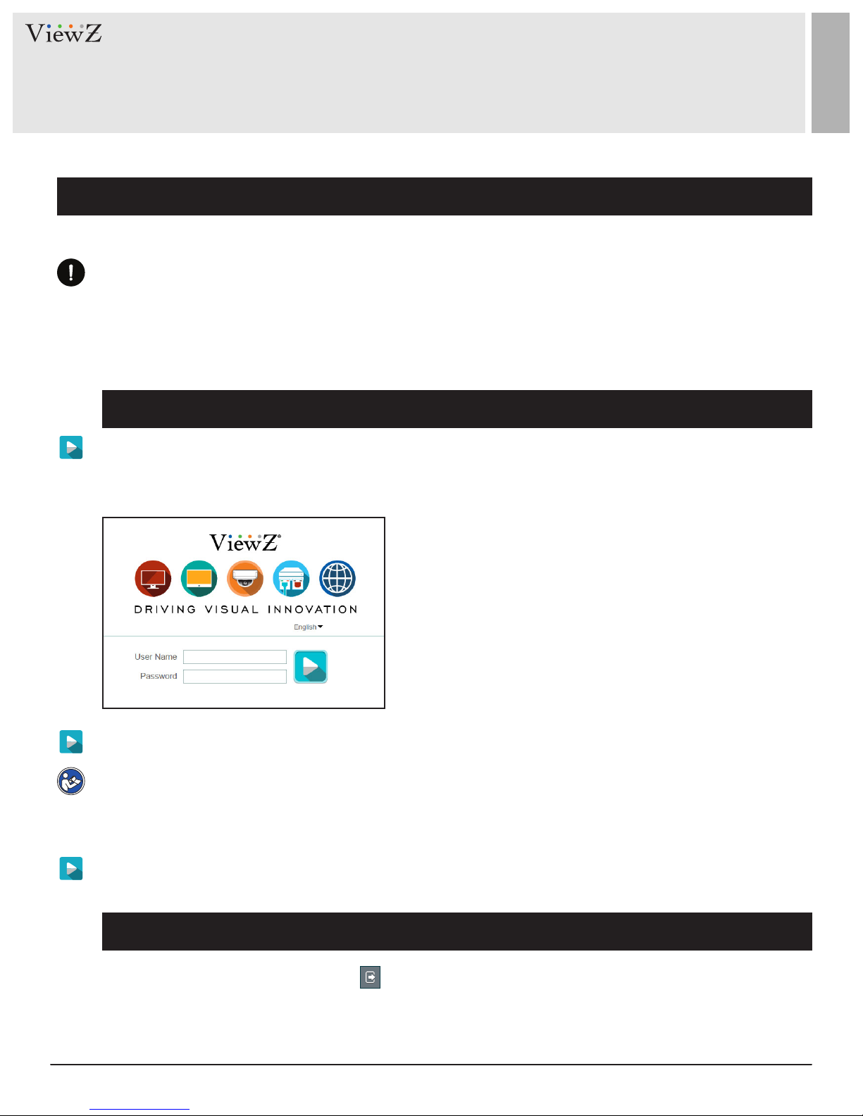
Step 1 Open Internet Explorer. Enter the IP address of the PVM IP camera (default value:
192.168.0.120) in the address box and then press Enter.
The login page is displayed, as shown in Figure 1-1.
Factory Default IP address : 192.168.0.120
Factory Default Subnet Mask : 255.255.255.0
Factory Default Gateway : 192.168.0.1
Factory Default DNS 1 : 192.168.0.1
Factory Default DNS 2 : 192.168.0.2
Cauon: IP address and gateway address should be set with the
same IP parameters. For example, if IP address is "A.B.C.0 ~
255", then gateway address should be set as "A.B.C.0~255"
(however, IP and gateway address cannot be the same.)
Figure 1-1 Login Page
Step 2 Enter the user name, and password
Note
• The default user name is admin and the default password is admin. Change the password when you log in
to the system for the rst me to ensure system security.
• You can change the system display language on the login page.
Step 3 Click Login. The main page will be displayed.
Logout
To log out of the system, click the icon in the upper right corner of the main page.
The login page is displayed aer you log out of the system.
6 User ManualVisit the ViewZ USA website at https://www.viewzusa.com
Page 7
QUICK REFERENCE GUIDE
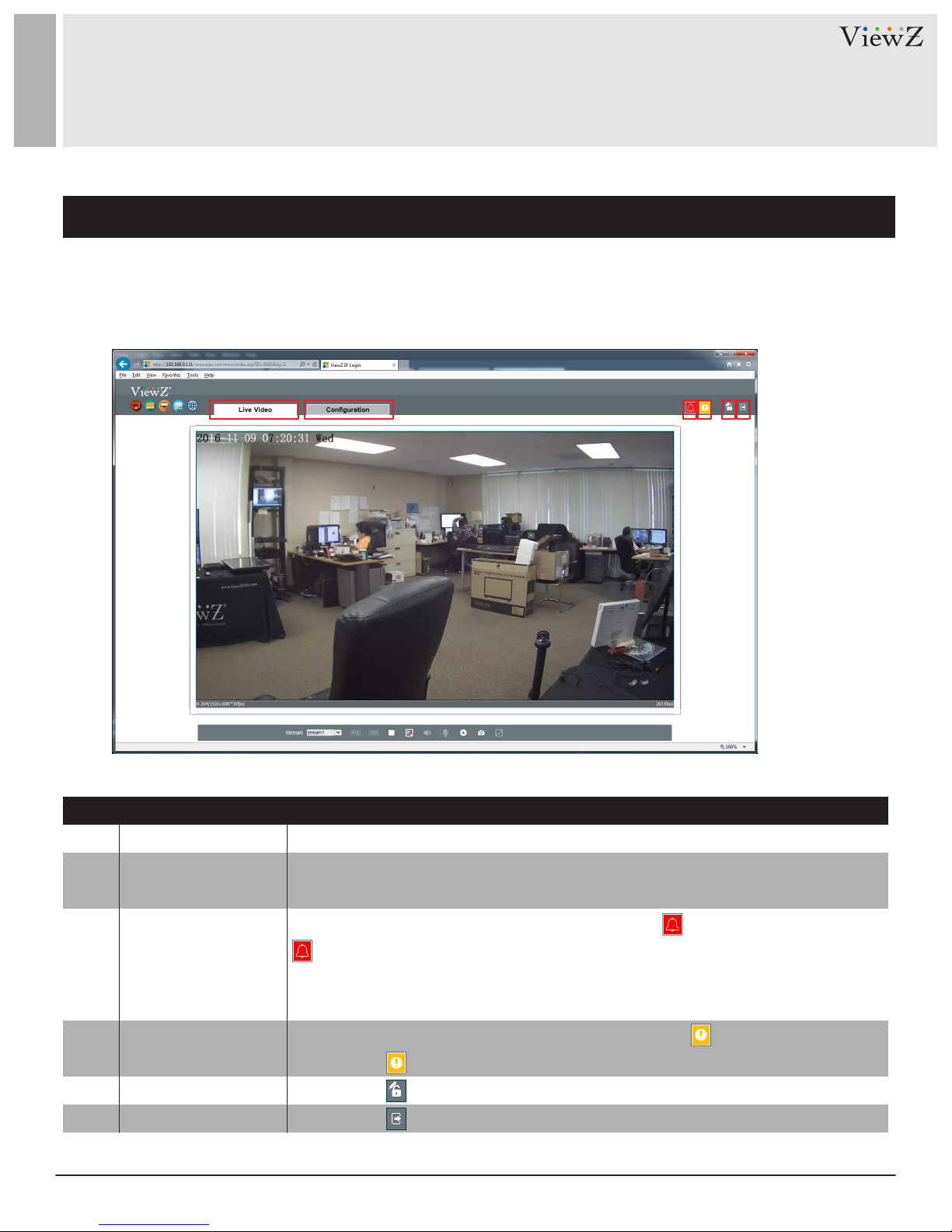
2. Main Page Layout
On the main page, you can see real-me video, receive alarm and fault nocaons, set parameters, change
the password, and log out of the system. Figure 1-2 shows the main page layout. Table 1-1 describes the
features on the main page.
q ew r ty
Figure 1-2 Main Page Layout
Table 1-1 Interface parameters
ELEMENTNo. DESCRIPTION
1
2
3
4
5 You can click to change the password.
6
LIVE VIDEO
CONFIGURATION
ALARM
FAULT
CHANGE PASSWORD
LOG OUT
Real-time video stream is displayed in this area. You can also set sensor parameters.
You can select options to set device configuration, including the device information,
audio and video streams, alarm setting, and privacy mask function.
When the device generates an alarm, the alarm icon is displayed. You can click
to view the alarm information.
NOTE : When the device accepts an alarm signal, the alarm icon will display
within 10s in the web management system.
When the device encounters an exception, the fault icon is displayed.
You can click to view the fault information.
You can click to return to the login page.
7User Manual Visit the ViewZ USA website at https://www.viewzusa.com
Page 8

QUICK REFERENCE GUIDE
3. Change the Password
Description
You can click to change the password for logging in to the system.
Procedure
Step 1 Click in the upper right corner of the main page.
The Change Password dialog box is displayed, as shown in Figure 1-3 and Figure 1-3-1.
Figure 1-3 Password Dialog Box
Step 2 Enter the old password, new password, and conrm the new password.
Step 3 Click OK.
If the message "Change own password success" is displayed, the password has been successfully changed. If
the password change fails, the cause will be displayed. (For example, the new password length couldn’t be
less than eight.)
Step 4 Enter the old password, new password, and conrm the new password.
8 User ManualVisit the ViewZ USA website at https://www.viewzusa.com
Figure 1-3-1 Password Change
Page 9
SEARCHING IP CAMERA
1. Searching Real Time IP Camera
You can browse real-me video in the web management system.
Preparation
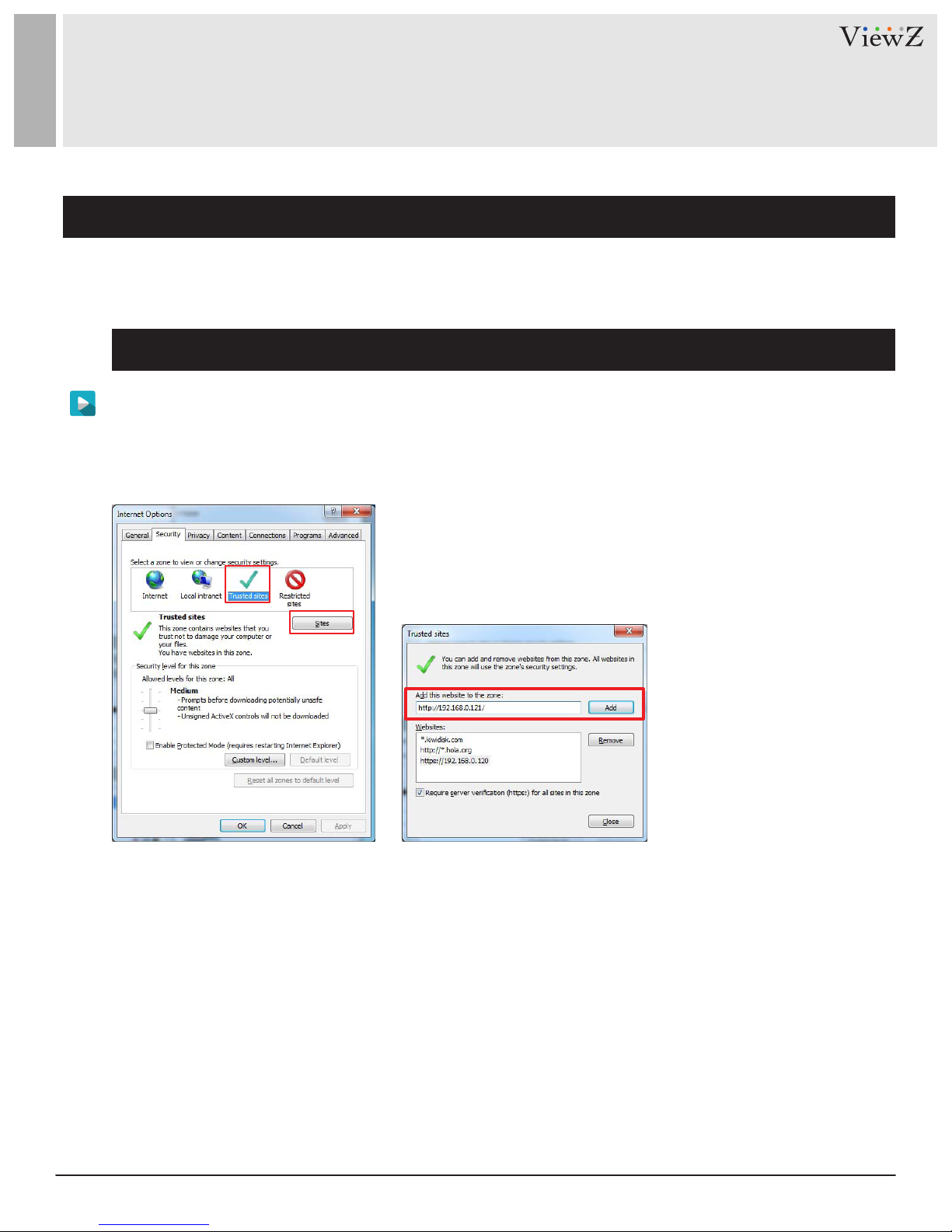
Step 1 To ensure that real-me video can be played properly, you must perform the following operaons
when you log in to the web management system for the rst me:
Open Internet Explorer. Choose Tools > Internet Opons > Security > Trusted sites > Sites.
In the displayed dialog box, click Add, as shown in Figure 2-1.
Figure 2-1 Add a trusted site
9User Manual Visit the ViewZ USA website at https://www.viewzusa.com
Page 10
SEARCHING IP CAMERA
1. Searching Real Time IP Camera
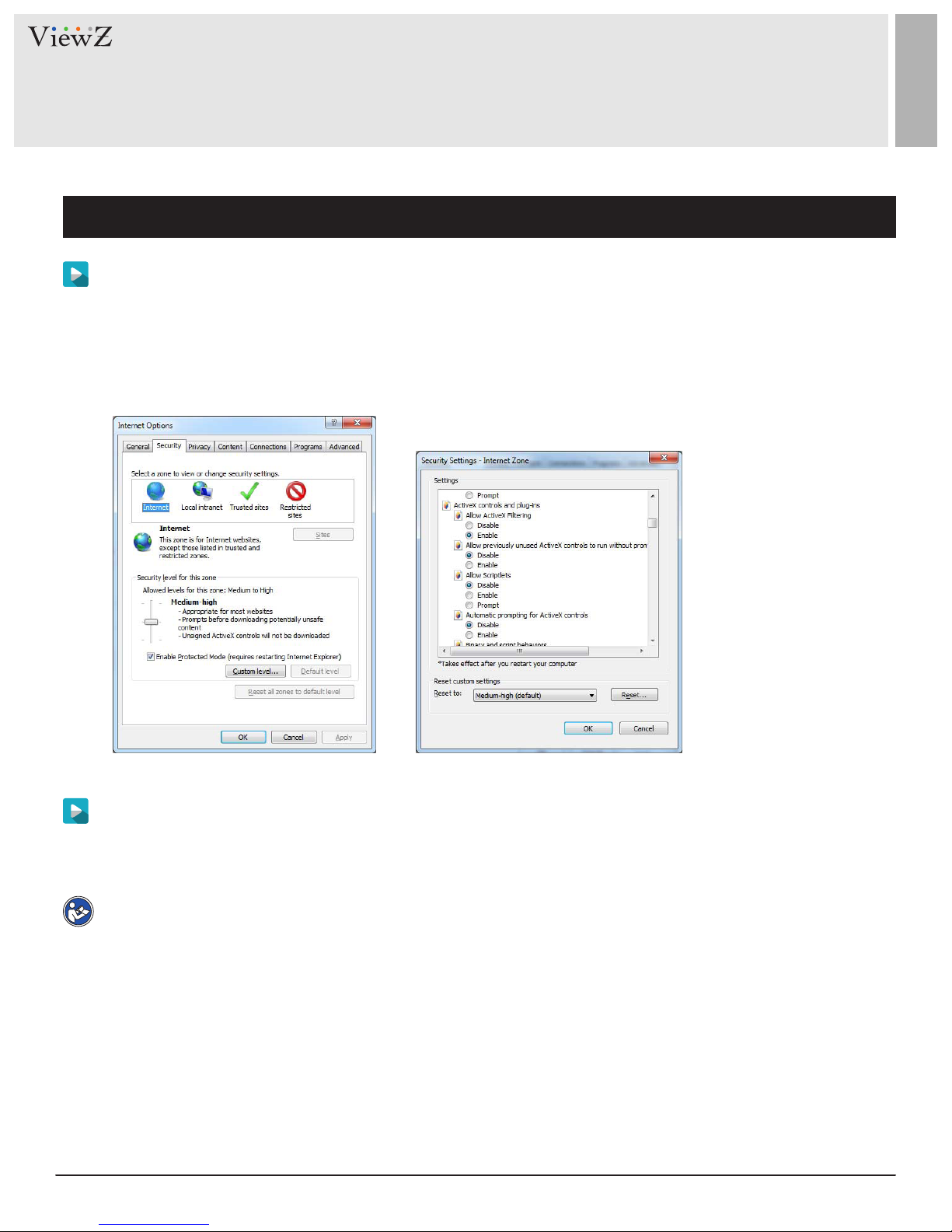
Step 2 In Internet Explorer, choose Tools > Internet Opons > Security > Customer level, and set Download
unsigned AcveX controls and Inialize and script AcveX controls not marked as safe for scripng under
AcveX controls and plug-ins to Enable, as shown in Figure 2-2.
Figure 2-2 Configure ActiveX controls and plug-ins
Step 3 Download and install the player control as prompted.
Note
• If the repair ps is prompted while installing the control, ignore the prompt and connue the installaon.
The login page is displayed when the control is loaded.
10 User ManualVisit the ViewZ USA website at https://www.viewzusa.com
Page 11
SEARCHING IP CAMERA
1. Searching Real Time IP Camera
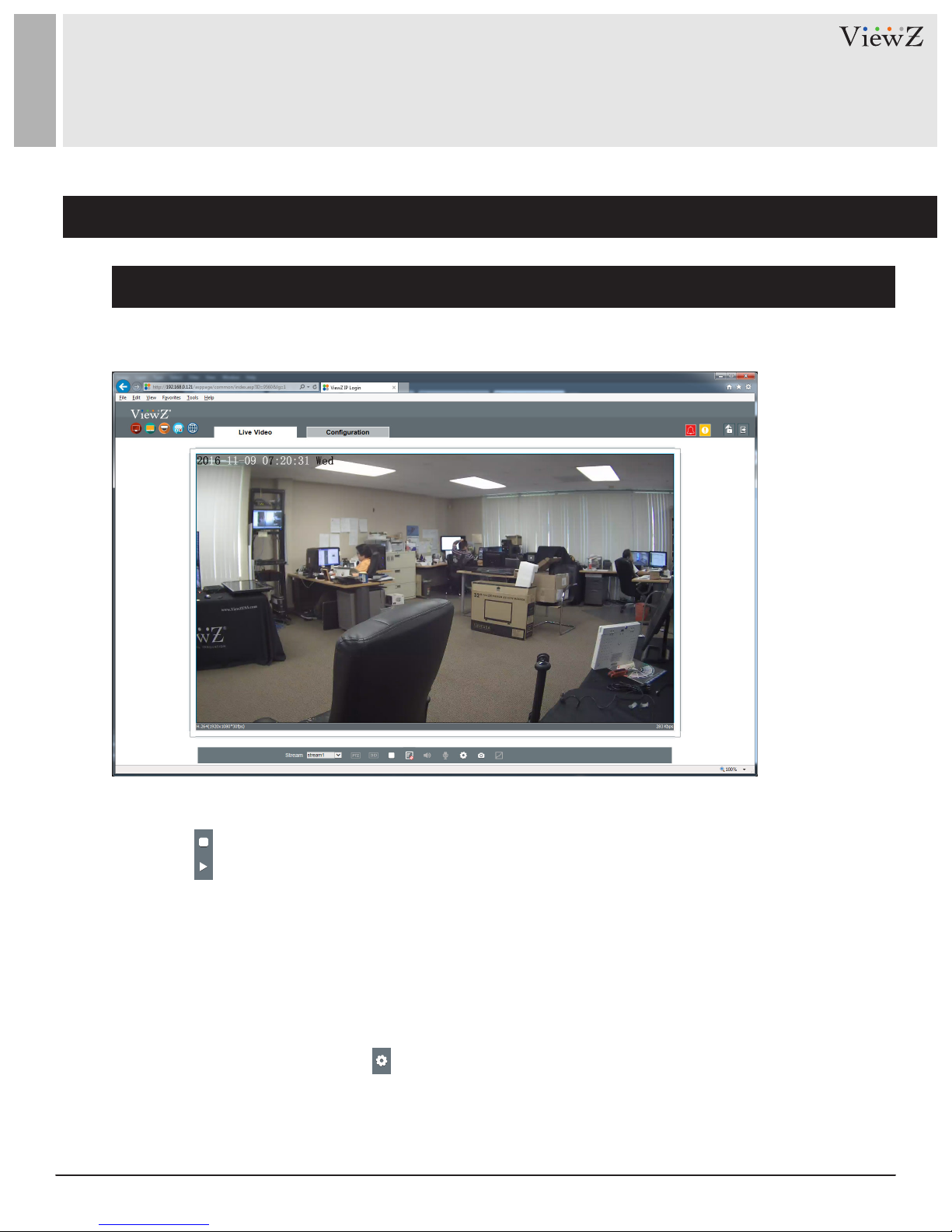
Description
To browse real-me videos, click Live Video. The Live Video page will be displayed, as shown in Figure 2-3.
Figure 2-3 Live Video
On the Live Video page, you can perform the following operaons:
• Click to stop the video.
• Click to play the video.
• Double-click in the video area to enter the full-screen mode, and double-click again to exit.
• Switch among preset streams 1, 2, and 3. For details about how to congure streams,
• See 3.2 Seng Video and Audio Stream Parameters.
• Congure the sensor.
You can right-click in the video area. A shortcut menu is displayed and allows you to enter the full-screen
mode, set sensor parameters, zoom in or out, and return to the default view.
To set sensor parameters, click to open the Sensor Seng page. On the Sensor Seng page, you can
adjust the image, mirror, camera mode, Iris seng, white balance, and noise lter.
11User Manual Visit the ViewZ USA website at https://www.viewzusa.com
Page 12
CONFIGURATION / DEVICE INFO
1. Configuration of IP PVM's Information
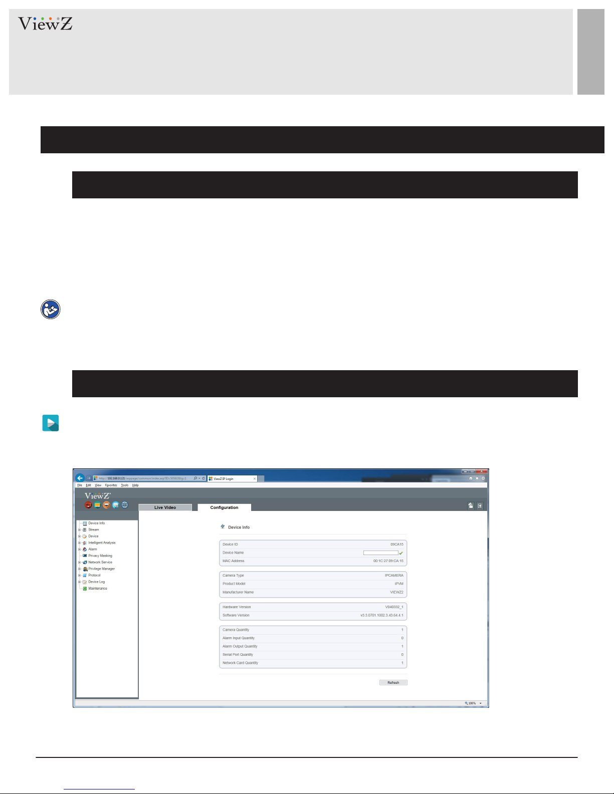
Description
The device informaon includes:
• Device ID, name, type, model, and MAC address.
• Hardware and soware versions.
• Number of video channels, number of alarm input channels, number of alarm output channels, and number of
serial ports.
Note
• You can modify the device name. All other parameters can only be viewed.
• When the device is upgraded, the device informaon will be updated automacally.
Procedure
Step 1 Click Conguraon > Device Info.
The Conguraon > Device Info page is displayed, as shown in Figure 3-1.
Figure 3-1 Device Info page
12 User ManualVisit the ViewZ USA website at https://www.viewzusa.com
Page 13
CONFIGURATION / DEVICE INFO
1. Configuration of IP PVM's Information
Procedure
Step 2 View the device informaon, set the device ID and name as shown in Table 3-1.
Table 3-1 Device parameters
SengParameter DESCRIPTION
Device ID
Device Name
MAC Address
Camera Type
Manufacturer ID
Manufacturer Name
Hardware Version
Soware Version
Video Channel(s)
Alarm Input(s)
Alarm Output(s)
Serial Port(s)
Unique device identifier used by the platform
to distinguish the devices.
Name of the device.
NOTE
The device name cannot exceed 32 bytes
or 10 simplified characters; otherwise, the
modification fails.
N/A
[Setting method]
The parameter cannot be modified.
[Setting method]
Enter a value manually.
[Setting method]
These parameters cannot be modified.
Network Card
Step 3 Click the icon
• If the message "Apply success!" is displayed, click Conrm to save the sengs.
• If the message "Apply failed!" is displayed, you must apply for the Parameter Congure permission from an
administrator. For details, see 10.1 Conguraon of Permission for Group.
13User Manual Visit the ViewZ USA website at https://www.viewzusa.com
Page 14
CONFIGURATION / STREAM
1. Setup Video and Audio Parameters
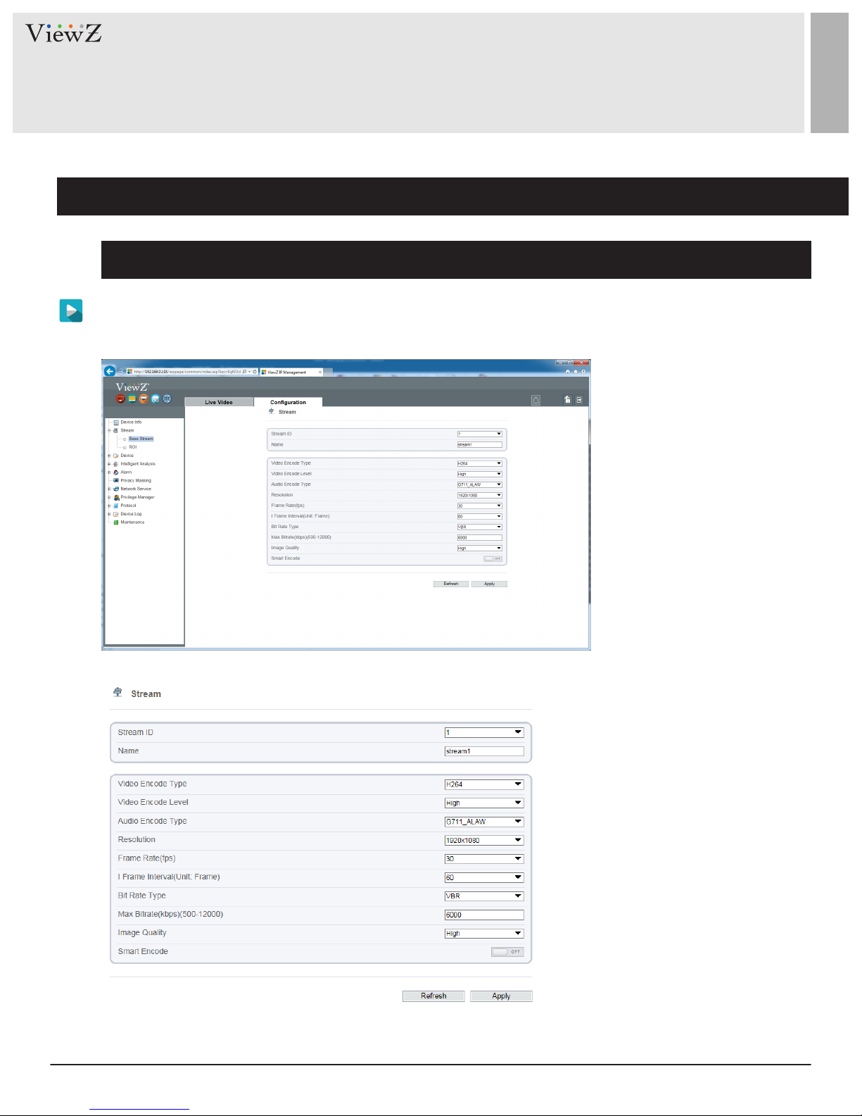
Procedure
Step 1 Click Stream Conguraon > Stream > Base Stream.
The Base Stream Conguraon page is displayed, as shown in Figure 4-1.
Figure 4-1 Stream Configuration page
14 User ManualVisit the ViewZ USA website at https://www.viewzusa.com
Page 15
CONFIGURATION / STREAM
1. Setup Video and Audio Parameters
Procedure
Step 2 Set the parameters as shown below in Table 4-1.
Table 4-1 Stream configuration parameters
SengParameter DESCRIPTION
Channel
Stream ID
Name
Video Encode Type
ID of the video output channel.
NOTE
An IP camera has only one video output channel.
Therefore, only the default value 1 is available.
The device supports two streams.
• Streams 1 and 2 use the H.264 Codec
• The maximum resolution can be set for streams 1
• Only a low resolution can be set for stream 2.
Stream name
NOTE
The stream name is combined with character,
number, character and underline.
The video codec determines the image quality and
network bandwidth required by a video. Currently,
the following codec standards are supported:
• MJPEG
MJPEG is a standard intra-frame compression
[Setting method]
Select a value from the drop-down
list box.
[Default value] 1
[Setting method]
Select a value from the drop-down
list box.
[Setting method]
Enter a value manually. The value
cannot exceed 32 bytes.
[Default value] stream1
[Setting method]
Select a value from the drop-down
list box.
[Default value] H.264 High Profile
NOTE
codec. The compressed image quality is good.
No mosaic is displayed on motion images.
MJPEG does not support proportional compression
and requires large storage space. Recording and
network transmission occupy large hard disk space
and bandwidth. MJPEG is not applicable to
continuous recording for a long period of time or
network transmission of videos. It can be used to
send alarm images.
The H.264 High Profile codec means
high requirements on the hardware.
If the hard decoding capability is low,
use H.264 Main Profile or H.264 Base
Profile.
15User Manual Visit the ViewZ USA website at https://www.viewzusa.com
Page 16

CONFIGURATION / STREAM
1. Setup Video and Audio Parameters
Procedure
Table 4-1 Stream configuration parameters
SengParameter DESCRIPTION
Video Encode Type
• H 264
H.264 consists of H.264 Base Profile, H.264 Main
Profile, and H.264 High profile.
The performance of H.264 High Profile is
higher than that of H.264 Main Profile, and the
performance of H.264 Main Profile is higher than
that of H.264 Base Profile.
If a hardware decoding device is used, select
the appropriate codec based on the decoding
performance of the device.
H.264 High Profile has the highest requirements on
the hardware performance, and H.264 Base Profile
has the lowest requirements on the hardware
performance.
• H.265
H.265 is the new video encoding standard ,it's the
improvement standard from H.264. H.265 improves
[Setting method]
Select a value from the drop-down
list box.
[Default value] H.264 High Profile
NOTE
The H.264 High Profile codec means
high requirements on the hardware.
If the hard decoding capability is low,
use H.264 Main Profile or H.264 Base
Profile.
the streams, encoding quality and algorithm
complexity to make configuration as optimization.
Audio Encode Type
16 User ManualVisit the ViewZ USA website at https://www.viewzusa.com
ID of the video output channel.
• G711_ULAW: mainly used in North America and Japan.
• G711_ALAW: mainly used in Europe and other areas.
• RAW_PCM: codec of the original audio data. This
codec is often used for platform data
[Setting method]
Select a value from the drop-down
list box.
Page 17
CONFIGURATION / STREAM
1. Setup Video and Audio Parameters
Procedure
Table 4-1 Stream configuration parameters
SengParameter DESCRIPTION
Resoluon
Frame Rate (fps)
I Frame Interval (f)
A higher resolution means better image quality
NOTE
IP cameras support the different resolutions
based on the model.
The frame rate is used to measure displayed frames.
A higher frame rate means smoother videos. A video
whose frame rate is higher than 22.5 f/s is considered
as smooth by human eyes.
Frame rates for different frequencies are as follows:
• 50 Hz: 1–25 f/s
• 60 Hz: 1–30 f/s
NOTE
The frequency is set on the Device Configuration
> Camera page. The biggest MJPEG coding format
frame rate is 12 frames per second.
I frames do not require other frames to decode.
A smaller I frame interval means better video quality
[Setting method]
Select a value from the drop-down
list box.
[Setting method]
Select a value from the drop-down
list box.
[Setting method]
Select a value from the drop-down
list box.
[Setting method]
Select a value from the drop-down
but higher bandwidth.
Bit Rate Type
The bit rate is the number of bits transmitted per unit
of time. The following bit rate types are supported:
• Constant bit rate (CBR)
The compression speed is fast; however, improper
bit rate may cause vague motion images.
• Variable bit rate (VBR)
The bit rate changes according to the image
complexity. The encoding efficiency is high and the
definition of motion images can be ensured.
list box.
[Setting method]
Select a value from the drop-down
list box.
17User Manual Visit the ViewZ USA website at https://www.viewzusa.com
Page 18
CONFIGURATION / STREAM
1. Setup Video and Audio Parameters
Procedure
Table 4-1 Stream configuration parameters
SengParameter DESCRIPTION
Max Bit Rate
(500-12000)
Quality
(500-12000)
Step 3 Click Apply
• If the message "Apply success!" is displayed, click Conrm. The system saves the sengs.
• If the message "Apply failed!" is displayed, you must apply for the Parameter Congure permission from an
administrator. For details, see 10.1 Conguraon of Permission for Group.
• If a message indicang that the bit rate is out of range is displayed, enter a new bit rate value.
Indicates the maximum value of the bit rate.
The video quality on the camera output.
[Setting method]
Enter a value manually.
[Setting method]
Slide the slider left or right
[Default value] 5
18 User ManualVisit the ViewZ USA website at https://www.viewzusa.com
Page 19
CONFIGURATION / STREAM
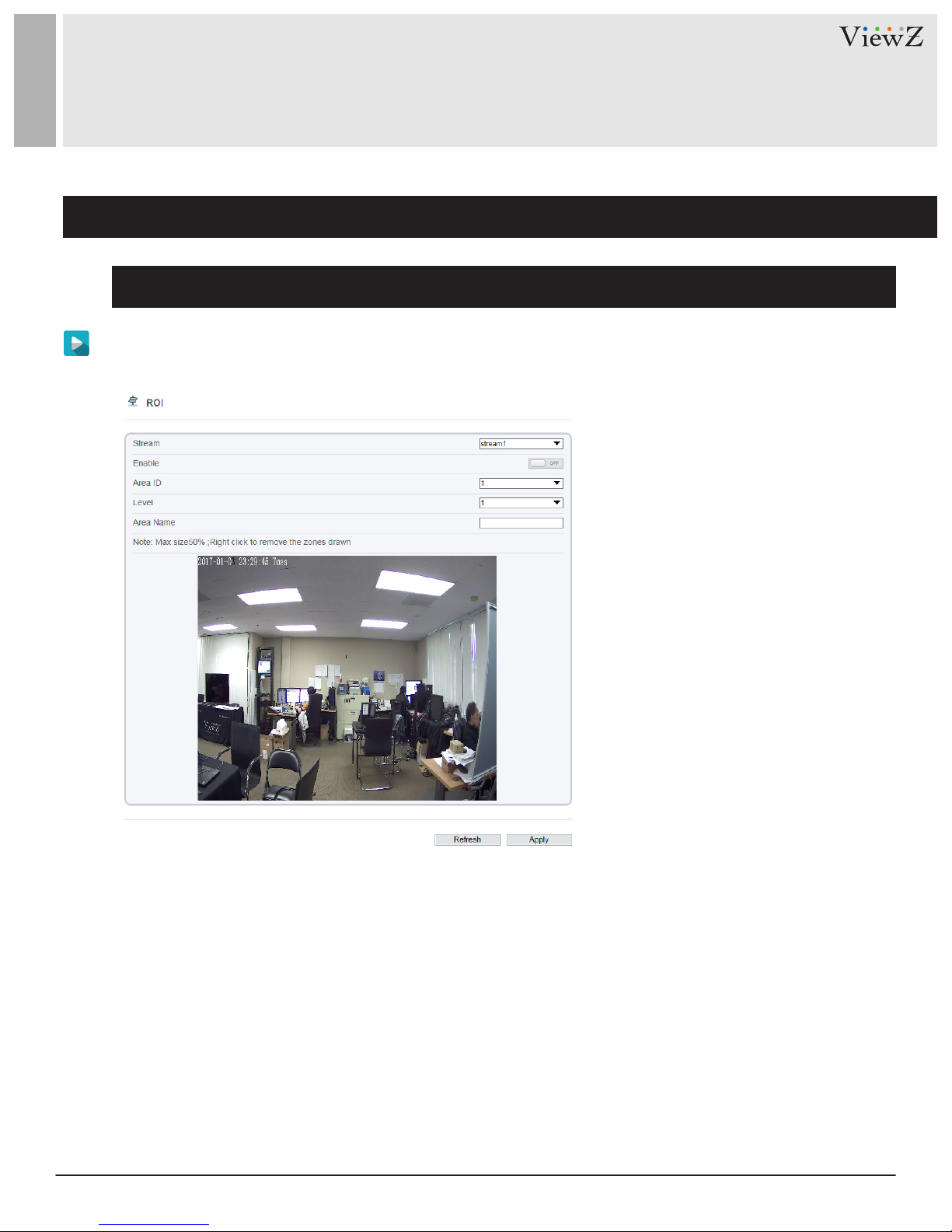
2. Setup ROI Parameters
* ROI - Region of Interest
Procedure
Step 1 Click Stream Conguraon > Stream > ROI.
The ROI Stream page is displayed, as shown in Figure 4-2.
Figure 4-2 ROI Stream Configuration page
19User Manual Visit the ViewZ USA website at https://www.viewzusa.com
Page 20
CONFIGURATION / STREAM
2. Setup ROI Parameters
Procedure
Step 2 Set ROI parameters as below in Table 4-2.
Table 4-2 ROI configuration parameters
SengParameter DESCRIPTION
Stream
Enable
Area ID
Level
Area Name
Stream name
Enable ROI function
ROI Area ID number
Refers to ROI Area image quality. Higher the level,
clearer the image within the ROI area and
blurrier the image outside the ROI area.
User can name the Area ID with special name
[Setting method] Pull-down and select
[Default value] Stream 1
[Setting method] Click to ON/OFF
[Default value] OFF
[Setting method] Pull-down and select
[Default value] 1
[Setting method] Pull-down and select
[Default value] 5
[Setting method] Name length
should be less than 32 Bytes
20 User ManualVisit the ViewZ USA website at https://www.viewzusa.com
Page 21
CONFIGURATION / DEVICE
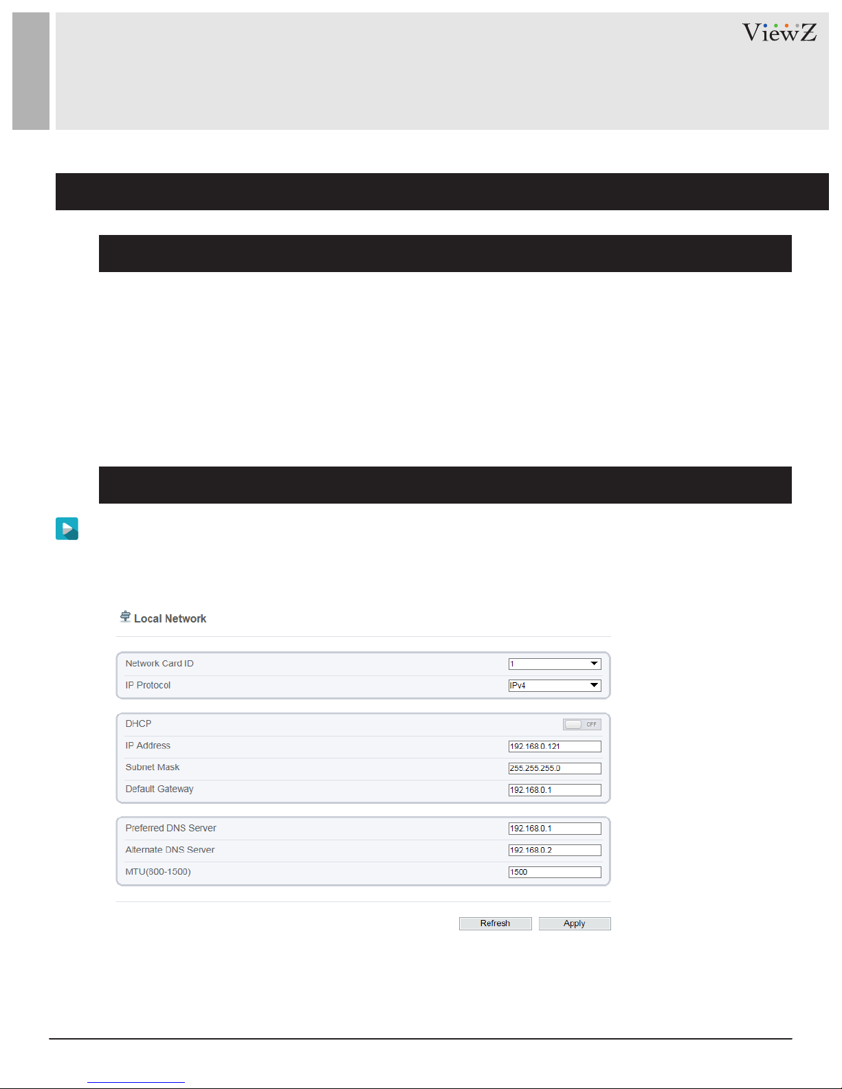
1. Setup Local Network Parameters
Description
Local network parameters include:
• IP protocol
• IP address
• Subnet mask
• Default gateway
• Dynamic Host Conguraon Protocol (DHCP)
• Preferred Domain Name System (DNS) server
• Alternate DNS server
• MTU
Procedure
Step 1 Choose Device Conguraon > Device > Local Network.
The Local Network page is displayed, as shown in Figure 5-1.
Figure 5-1 Local Network page
21User Manual Visit the ViewZ USA website at https://www.viewzusa.com
Page 22
CONFIGURATION / DEVICE
1. Setup Local Network Parameters
Procedure
Step 2 Set the parameters according to Table 5-1.
Table 5-1 Local network parameters
SengParameter DESCRIPTION
IP Protocol
Obtain IP address
automacally
DHCP IP
IP Address
Subnet Mask
Default Gateway
IPv4 is the IP protocol that uses an address length of
32 bits.
The device automatically obtains the IP address from
the DHCP server.
IP address that the DHCP server assigns to the device.
Device IP address that can be set as required.
Subnet mask of the network adapter.
This parameter must be set if the client accesses the
device through a gateway.
[Setting method] Select a value
from the drop-down list box.
[Default value] IPv4
[Setting method]
Click the button on to enable obtaining
IP address automatically
NOTE : To query the current
IP address of the device, you must
query it on the platform based on the
device name.
N/A
[Setting method]
[Default value] 192.168.0.120
[Setting method]
[Default value] 255.255.255.0
[Setting method]
[Default value] 192.168.0.1
Enter a value manually.
Enter a value manually.
Enter a value manually.
Preferred DNS Server
Alternate DNS Server
MTU
22 User ManualVisit the ViewZ USA website at https://www.viewzusa.com
IP address of a DNS server.
IP address of a domain server.
If the preferred DNS server is faulty, the device uses
the alternate DNS server to resolve domain names.
Set the maximum value of network transmission
data packets.
[Setting method]
[Default value] 192.168.0.1
[Setting method]
[Default value] 192.168.0.2
[Setting method]
NOTE
800 to 1500, with the default value at 1500.
Please do not change it arbitrarily.
Enter a value manually.
Enter a value manually.
Enter a value manually.
The MTU value ranges from
Page 23

CONFIGURATION / DEVICE
1. Setup Local Network Streaming
Procedure
Step 3 Click Apply.
• If the message "Apply success!" is displayed, click Conrm. The system saves the sengs. The message
"Set network parameter success, Please login system again" is displayed. Use the new IP address to log in
to the web management system.
• If the message "Invalid IP Address", "Invalid Subnet Mask", "Invalid Default Gateway", "Invalid Primary
DNS", or "Invalid Space DNS" is displayed, set the parameters correctly.
23User Manual Visit the ViewZ USA website at https://www.viewzusa.com
Page 24
CONFIGURATION / DEVICE
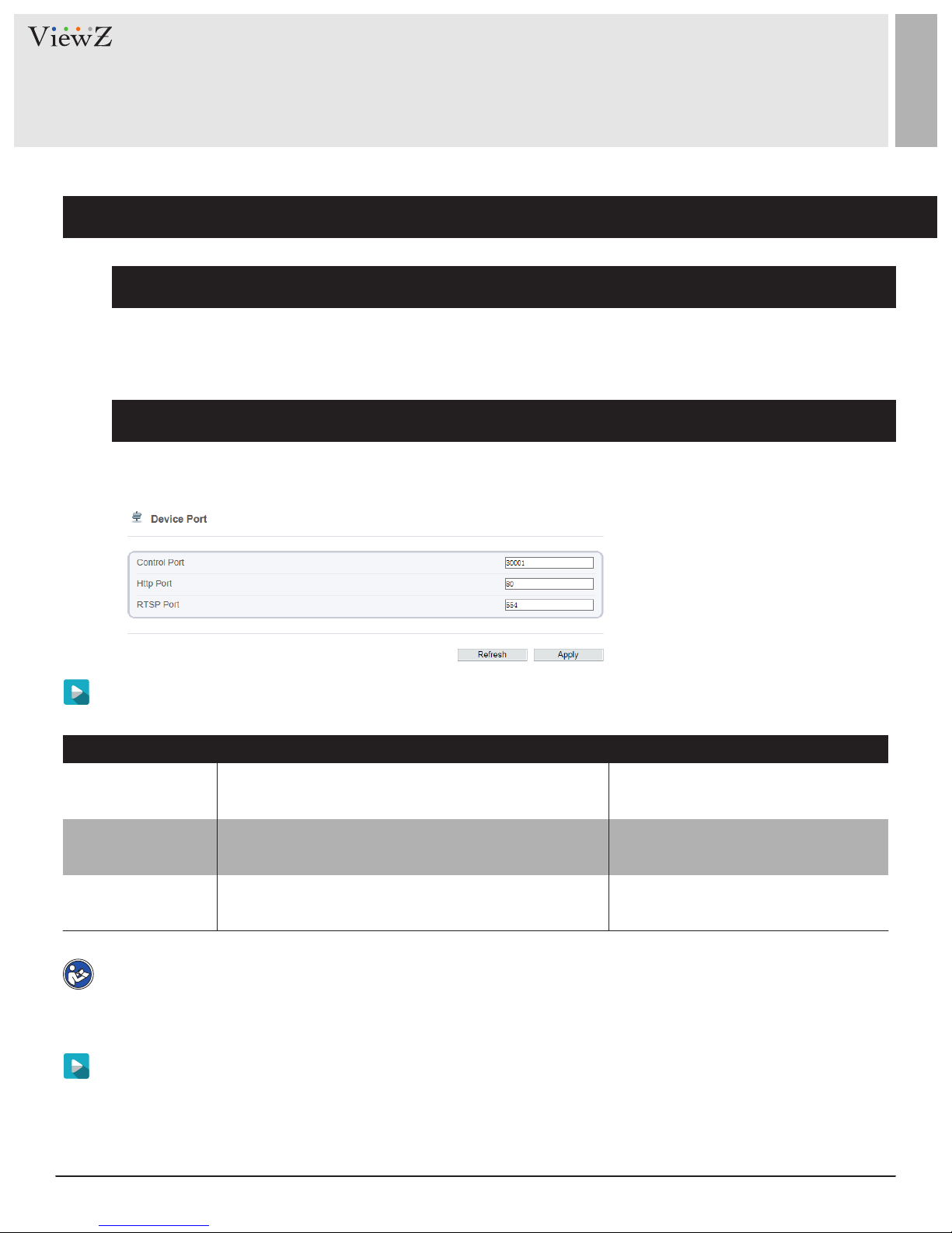
2. Configuration of Device Ports
Description
You must congure the HTTP port, control port, Real Time Streaming Protocol (RTSP) port and RTMP port for
device route mapping in a LAN.
Procedure
Step 1 Choose Device Conguraon > Device > Device Port.
The Device Port page is displayed, as shown in Figure 5-2.
Table 5-2 Device port parameters
Step 2 Set the parameters according to Table 5-2
Table 5-2 Device port parameters
Control Port
HTTP Port
RTSP Port
Note
It’s not recommended to modify the control port. For details about the value ranges of the control port,
HTTP port, RTSP port and RTMP port, see the communicaon matrix.
Step 3 Click Apply.
• If the “This operaon will lead to the device to restart, connue?” dialog box is displayed, click Conrm.
The system automacally restarts and saves the sengs.
• If the message "Invalid Control Port, Please input an integer between 1025 and 65535" is displayed, enter
correct port numbers.
Port used for audio and video transfer and
signaling interaction
Port used in web access
RTSP protocol port
SengParameter DESCRIPTION
[Setting method]
[Default value] 30001
[Setting method]
[Default value] 80
[Setting method]
[Default value] 554
Enter a value manually
Enter a value manually
Enter a value manually
24 User ManualVisit the ViewZ USA website at https://www.viewzusa.com
Page 25
CONFIGURATION / Device
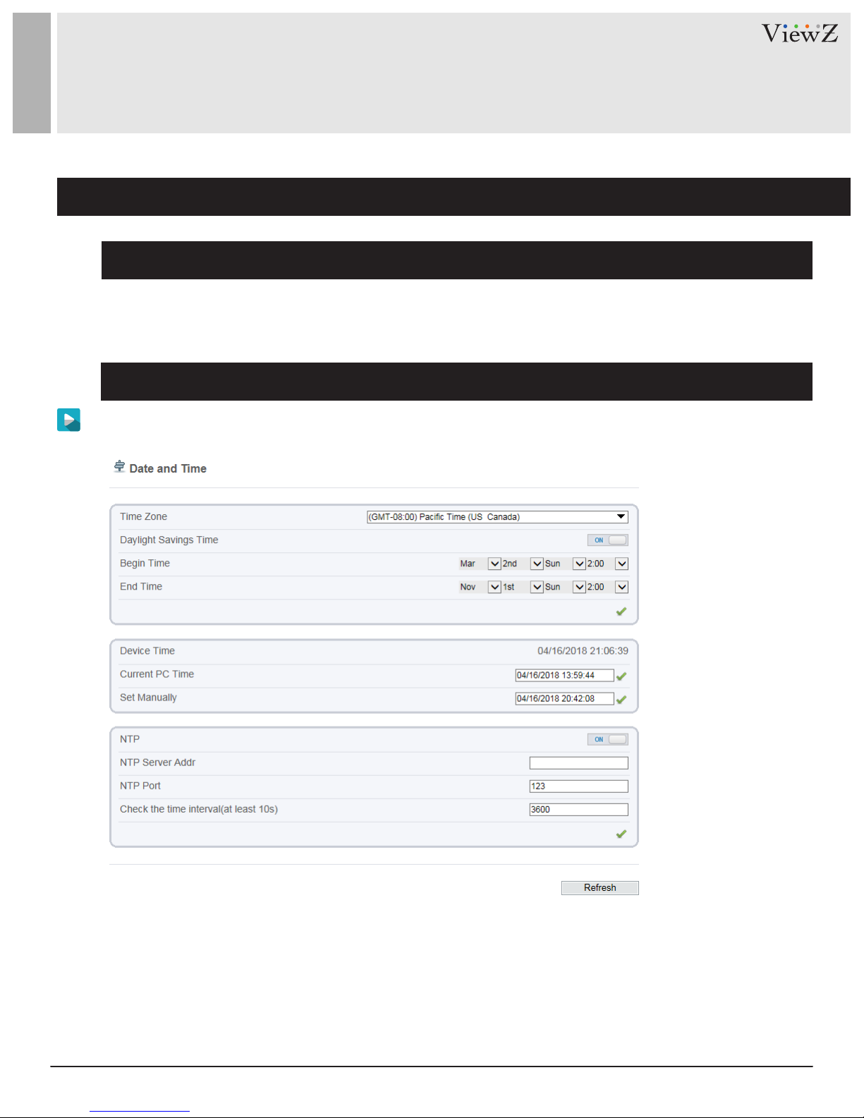
3. Configuration of the Date and Time
Description
On the Date & Time page, you can modify the date and me.
Procedure
Step 1 Choose Device Conguraon > Device > Date and Time.
The Date page is displayed, as shown in Figure 5-3. Table5-3 describes the parameters.
Figure 5-3 Time and Date page
25User Manual Visit the ViewZ USA website at https://www.viewzusa.com
Page 26
CONFIGURATION / Device
3. Configuration of the Date and Time
Procedure
Table 5-3 Time parameters
Parameter DESCRIPTION
Seng
Time Zone
Adjust clock for
daylight saving changes
Device Time
N / A
When the DST start time arrives, the device time
automatically goes forward one hour. When the DST
end time arrives, the device time automatically goes
backward one hour.
NOTE
DST is the practice of advancing clocks so that
evenings have more daylight and mornings have
less. Currently, about 110 countries in the world
use DST. Different countries have different DST
provisions. Since March 27, 2011, Russia has
started to use permanent DST.
Device display time.
[Setting method] Select a value
from the drop-down list box.
[Default value]
Greenwich mean time
[Setting method]
Click the button on to enable Adjust
clock for daylight saving changes.
[Setting method]
• Synchronize the time from the PC.
Current PC Time
Set Manually
NTP
NTP Port
Check the me
interval( at least 10s)
26 User ManualVisit the ViewZ USA website at https://www.viewzusa.com
Time on the current PC.
Enables you to manually set the device time.
IP address or domain name of the NTP server.
Port number of the NTP server.
Set time interval to check if the device time
synchronizes with the NTP server time.
• Enter a value manually.
N / A
[Setting method] Click Set Manually
and set the date and time in the
format YYYY-MM-DD HH:MM:SS.
[Setting method] Click the button
on to enable NTP and enter a value manually.
[Setting method]
[Default value] 123
[Setting method]
[Default value] 3600
Enter a value manually.
Enter a value manually.
Page 27
CONFIGURATION / DEVICE
3. Configuration of the Date and Time
Procedure
Step 2 Select a me zone from the Time Zone drop-down list box.
Step 3 (Oponal) Click the buon on to enable Adjust clock for daylight saving changes and specify the DST
start me and end me.
Step 4 Modify the device me.
• Synchronizing me from the PC
Click Current PC Time.
• Manually seng the device me
− Click Set Manually.
A me seng control is displayed.
− Set the date and me.
Step 5 Congure the NTP.
1. Click the buon on to enable NTP.
2. Enter the IP address or domain name of the NTP server and the port number.
Step 6 Click the icon
The message "Apply success!" is displayed.
Step 7 Click Conrm
The system saves the sengs.
27User Manual Visit the ViewZ USA website at https://www.viewzusa.com
Page 28

CONFIGURATION / DEVICE
4. Setup Channel Name, Video and Source Resolution
Procedure
Step 1 Choose Device Conguraon > Device > Camera.
The Camera page is displayed, as shown in Figure 5-4. Table 5-4 describes the parameters.
Figure 5-4 Camera page
Table 5-4 Camera parameters
Camera
Channel Name
Video System
Video Refresh
Frequency
ID of the video output channel.
Channel name within the length of 0 to 32 bytes.
The options are as follows:
• PAL: Used in Europe and China mainland.
• NTSC: Used in USA and Japan.
The options are as follows:
• 50 Hz: corresponds to the PAL system.
• 60 Hz: corresponds to NTSC system.
SengParameter DESCRIPTION
[Setting method] Select a value
from the drop-down list box.
[Default value] 1
[Setting method]
Enter a value manually.
[Setting method] Select a value
from the drop-down list box.
[Default value] PAL
NOTE
can be changed depends on the device model
[Setting method] Corresponds to
the video system.
Whether the video system
28 User ManualVisit the ViewZ USA website at https://www.viewzusa.com
Page 29
CONFIGURATION / DEVICE
4. Setup Channel Name, Video and Source Resolution
Procedure
Step 2 Enter a channel name
Note : The channel name must be within the length of 0 to 32 bytes, it is combined with digital and character
(except for some special character).
Step 3 Click the icon
The message "Apply success!" is displayed.
Step 4 Click Conrm. The system saves the sengs.
Note : If the video system and source resoluon are modied, the message "The device will restart, are you
sure to modify?" is displayed, and the system automacally saves the sengs. The sengs take eect aer the
device restarts.
29User Manual Visit the ViewZ USA website at https://www.viewzusa.com
Page 30
CONFIGURATION / DEVICE
5. Setup OSD Parameters
Description
The on-screen display (OSD) funcon allows you to display the device name, channel ID and name, me, and
other customized content on videos.
• When the resoluon is D1 and CIF, the maximum number of words that can be displayed is 22 words
• The OSD supports English, digital and some special characters only.
Procedure
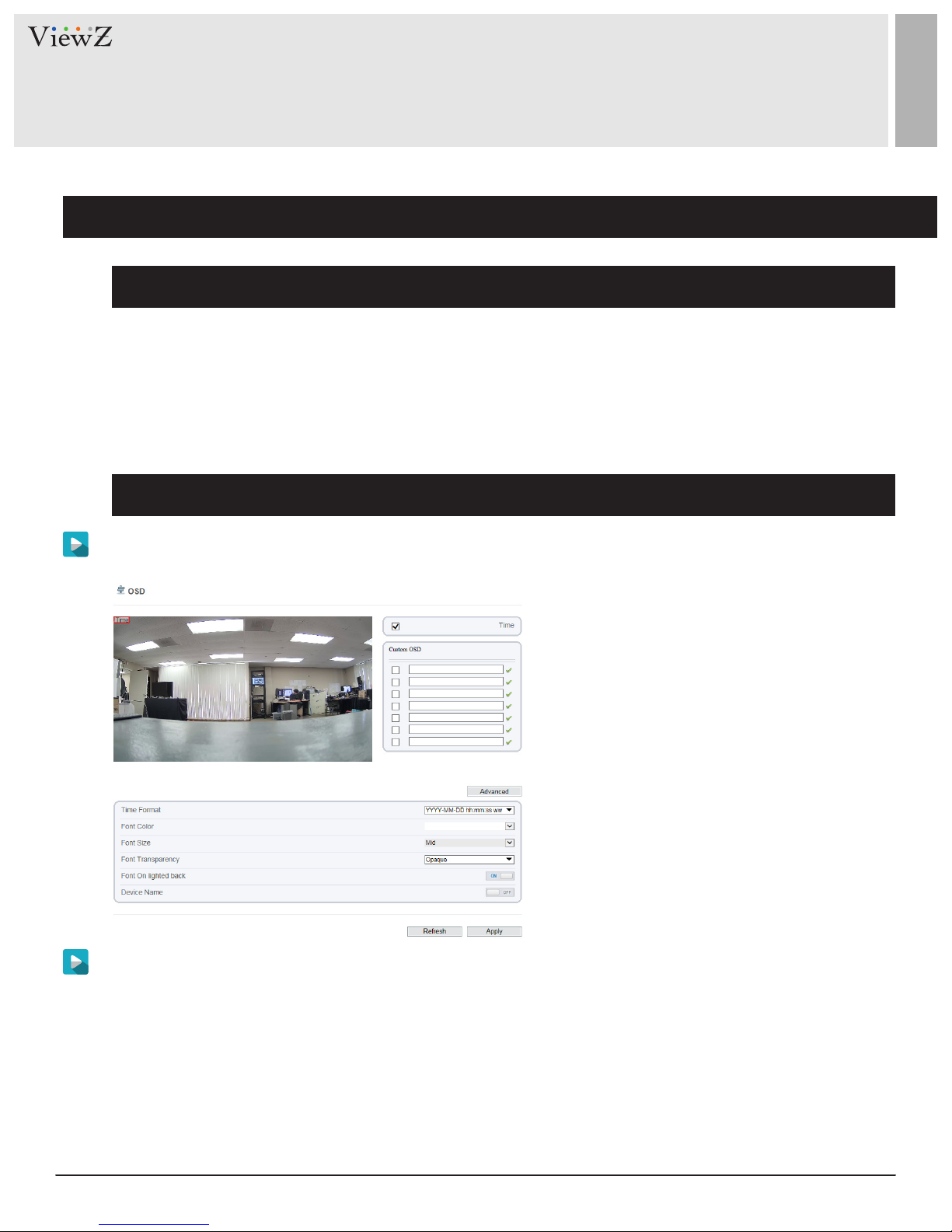
Step 1 Choose Device Conguraon > Device > OSD.
The OSD page is displayed, as shown in Figure 5-5.
Figure 5-5 OSD page
Step 2 Set the parameters according to Table 5-5.
The size of characters that can be displayed in a row or column varies according to the resoluon. When the
OSD font is auto:
• If the resoluon is 1920 x 1080 and the size of each character is 48 x 48, then the maximum row of OSD is
22 (1080/48), and the maximum column is 40 (1920/48);
• If the resoluon is 704 x 576 and the size of each character is 32 x 32, then the maximum row of OSD is 18
(576/32), and the maximum column is 22 (704/32);
• If the resoluon is 640 x 360 and the size of each character is 16 x 16, the maximum row of OSD is
22(360/16) characters, and a maximum column is 40(640/16).
30 User ManualVisit the ViewZ USA website at https://www.viewzusa.com
Page 31

CONFIGURATION / DEVICE
5. Setup OSD Parameters
Procedure
Table 5-5 OSD parameters
SengParameter DESCRIPTION
Time
Device Name
Custom OSD
Time Format
Font Color
Indicates whether to display the time
Indicates whether to display the device name
on videos.
Create the message box
Format in which the time is displayed.
Set the font color.
[Setting method] Check the blank box
to display the time.
[Setting method] Check the blank box
to display the device name.
[Default value] Off
[Setting method] Check one of the
blank boxes and write a value within
the lengh of 0 to 32 characters in
custom OSD. Click the icon to
apply custom OSD value.
[Default value] Blank
[Setting method] Select a value
from the drop-down list box.
[Default value]
YYYY-MM-DD hh:mm:ss ww
[Setting method] Select a value
from the drop-down list box.
Font Size
Font Transparency
Font on lighted back
Set the font size
Set the font transparency on lighted back.
Enable the font on lighted back.
[Default value] Blank
[Setting method] Select a value
from the drop-down list box.
[Default value] Mid
[Setting method] Select a value
from the drop-down list box.
[Default value] Opaque
[Setting method] Click the button on
to enable Font on lighted back.
[Default value] Off
31User Manual Visit the ViewZ USA website at https://www.viewzusa.com
Page 32

CONFIGURATION / DEVICE
5. Setup OSD Parameters
Procedure
Step 3 Click Apply
The message "Apply success!" is displayed.
Step 4 Click Conrm. The system saves the sengs.
32 User ManualVisit the ViewZ USA website at https://www.viewzusa.com
Page 33

CONFIGURATION / DEVICE
6. Configuration of Analog Output (CVBS)
Preparation
Connect a display device to the VIDEO OUT port.
Description
When the analog output funcon is enabled, the IP camera can send analog signals to a video server or display
device through the VIDEO OUT port.
Procedure
Step 1 Choose Device Conguraon > Device > CVBS
The BNC Video Output page is displayed, as shown in Figure 5-6.
Figure 5-6 BNC config page
Step 2 Click the buon on to enable BNC Video Output.
Step 3 Click Apply. The message "Apply success!" is displayed.
Step 4 Click Conrm. The system saves the sengs.
33User Manual Visit the ViewZ USA website at https://www.viewzusa.com
Page 34

CONFIGURATION / DEVICE
7. Configuration of System Language & Webmode
Description
On the System Conguraon page, you can congure the language used by the me displayed in the video
window and alarm emails and web mode.
Procedure
Step 1 Choose Device Conguraon > Device > System.
The System page is displayed, as shown in Figure 5-7
Figure 5-7 System configuration page
Step 2 Select a language from the language drop-down list box. The default language is English.
Step 3 Click the icon
The message "Apply success!" is displayed.
Step 4 Click Conrm. The system saves the sengs.
Step 5 Select a web mode from the web mode drop-down list box.
Step 6 Click the icon
The message "This operaon will lead to the device to restart, connue?".
Step 7 Click Conrm. The message "Apply success!" is displayed, the system restart.
34 User ManualVisit the ViewZ USA website at https://www.viewzusa.com
Page 35

CONFIG. /INTELLIGENT ANALYSIS
Overview
Terminology
• Field of View: the whole screen that a camera is capable of displaying.
• Deployment Area: the sll area with any shape in the eld of view set by a user.
• Target: the moving object of a certain type (human, vehicle, human or vehicle) appearing in the eld of
view.
• False Alarm: a false alarm generated because of interference sources (such as illuminaon change, leaf
waggle and shadow).
• Alarm missing: an alarm meeng user-dened target trigger sengs but not alarm.
Operating Environment
• Intelligent analysis available only on Hisilicon currently
• Operang system: Microso Windows 7/Windows XP (32/64-bit operang system supported)
• CPU: Intel core i3 and above / Memory: 1 GB and above / Display: resoluon 1024*768 or above
Note : The soware does not support pure 64-bit system. The 64-bit system menoned above supports 32-bit
soware.
Precautions
Precauons for Installaon
• The camera stays level with the horizon, without inclinaon.
• The installaon height is more than 2 m indoors and within 5-8 m outdoors. If climbing over the wall needs
to be monitored, the camera height can be 2 m higher than the wall.
• The angle of depression is larger than 150 & Do not install the device against the light.
• Try to install the device in a place where the light reecon from ground is weak in case of indoor
installaon.
• Try to keep the sky out of the eld of view, because false alarms may be generated due to illuminaon
changes or cloud movement.
Other Precauons
• Try to disable automac white balance, the switch of which tends to cause alarm missing.
• Set the camera to be xed focus.
• Do not switch from color mode to black&white mode frequently, otherwise, alarm missing occurs.
• Try not to use the Infrared all-in-one machine outdoors, which aracts insects and causes false alarms.
• The target cannot be oversized or undersized. The minimum target detectability is 8*8 pixels. The target
takes up 1/20-1/2 of the screen in height, excess of which leads to alarm missing.
• T
he background modeling aer parameter seng needs 4-8 seconds, during which a triggered alarm is not reported.
• A certain period of me is required from target appearance to recognion, so the duraon of a target
appearing in the eld of view normally needs to be more than 2 seconds.
• Avoid too many moving targets in the eld of view, which may lead to alarm missing.
• The ll-in light at night needs to be uniform.
• The wide-angle lens with short focal length (less than 4 mm) is recommended for small indoor space.
35User Manual Visit the ViewZ USA website at https://www.viewzusa.com
Page 36

CONFIG. /INTELLIGENT ANALYSIS
1. Perimeter
Description
The perimeter funcon refers the alarm that is generated when the targets of specied types (such as human,
vehicle and both) enter the deployment area.
Settings
Step 1 Select Conguraon > Intelligent Analysis > Perimeter to access the Perimeter interface, as shown in
Figure 6-1
Figure 6-1 Perimeter Setting Interface
Step 2 Set all parameters for perimeter. Table 6-1 describes the specic parameters
36 User ManualVisit the ViewZ USA website at https://www.viewzusa.com
Page 37

CONFIG. /INTELLIGENT ANALYSIS
1. Perimeter
Settings
Table 6-1 Perimeter Parameter Description
SengParameter DESCRIPTION
Alarm Interval
(1-1800s) Enter a value in the area box.
Limit Target Type
Limit Target Size
An alarm is generated when objects enter the
deployment area, it is generated again in next intervals
(alarm interval) until the end of event.
Setting range: 1-1,800 seconds.
Effective alarms are set based on target type, with
options of human, vehicle, or both. When the device is
used indoors, because of small space and large targets,
alarms are triggered by human sometimes even if
vehicle is selected, leading to false alarms. It is
recommended to set the target type to human for
indoor use.
The target size for triggering an effective alarm is set
based on the actual target size. The default value is
1000-100000 square centimeters and the setting range
is 0-1000000 square centimeters. When setting the
target size, you need to accurately set ”Real size in
scene” in advanced parameters, otherwise no alarms
[How to set]
[Default Value] 10
[How to set]
Click to enable Limit Target Type.
[Default Value] Off
[How to set]
Click to enable Limit Target Size.
[Default Value] Off
may be generated.
Upload Target Info
Enable the function of uploading target information by
clicking below the Live video in a flash browser
to turn into . When an alarm is triggered, the
target movement trace can be displayed (The trace
can be seen only within the deployment area and
disappears after the target leaves the deployment
area)
[How to set]
Click to enable Upload Target Info.
[Default Value] OFF
37User Manual Visit the ViewZ USA website at https://www.viewzusa.com
Page 38

CONFIG. /INTELLIGENT ANALYSIS
1. Perimeter
Settings
Table 6-1 Perimeter Parameter Description
SengParameter DESCRIPTION
Output Channel
SMTP
If you check to set the Output Channel and the device
is connected to an external alarm indicator, the alarm
indicator signals when an alarm is triggered.
If you turn on, system will send a notice email.
You can set the email on Network Service / SMTP.
[How to set]
Click the parameter and input an ID.
[Default Value] OFF
Deployment Time Settings
Seng deployment me: Click to select any me point within 0:00-24:00 from Monday to Sunday; or hold
down the le mouse buon, drag and release the mouse to select the deployment me within 0:00-24:00
from Monday to Sunday, and then click Apply to successfully set the me. Note: When you select me by
dragging the cursor, the cursor cannot be moved out of the me area. Otherwise, no me can be selected.
Deleng deployment me: Select the week on the le of set me which becomes red aer selecon,
as shown in Figure 6-2, and then click Delete to erase the deployment me. You can also delete selected
deployment me by means of inverse selecon.
Figure 6-2 Deployment Time Setting Interface
38 User ManualVisit the ViewZ USA website at https://www.viewzusa.com
Page 39

CONFIG. /INTELLIGENT ANALYSIS
1. Perimeter
Deployment Area Settings
Draw a deployment area: Move the cursor to the drawing interface, click the le mouse buon and drag
the mouse to generate a green rectangle, which forms a deployment area. You can also click the square grid in
the interface to set the deployment area. Click "clear" to delete the deployment area, as shown in Figure 6-3.
Figure 6-3 Deployment Area Setting Interface
Note
• A drawn line cannot cross another one, or the line drawing fails.
• Any shape with 32 sides at most can be drawn.
• The quanty of deployment areas is not limited yet and will be described in future when a limit is applied.
39User Manual Visit the ViewZ USA website at https://www.viewzusa.com
Page 40

CONFIG. /INTELLIGENT ANALYSIS
2. Single Virtual Fence
Function Definition
A single virtual fence is a line that is set at a concerned posion within the monitored eld of view and
species the forbidden travel direcon. An alarm is generated when the specied types of targets (such as
human or vehicle) cross this line.
Function Settings
Step 1 Select Conguraon > Intelligent Analysis > Single Virtual Fence to access the Single Virtual Fence
seng interface, as shown in Figure 6-4
Figure 6-4 Single Virtual Fence Setting Interface
Step 2 Set all parameters for the single virtual fence. Table 6-2 describes the specic parameters.
40 User ManualVisit the ViewZ USA website at https://www.viewzusa.com
Page 41

CONFIG. /INTELLIGENT ANALYSIS
2. Single Virtual Fence
Settings
Table 6-2 Single Virtual Fence Parameter Description
SengParameter DESCRIPTION
Alarm Interval
(1-1800s) Enter a value in the area box.
Limit Target Type
Limit Target Size
An alarm is generated when target cross the single
virtual fence, it is generated again in next intervals
(alarm interval) until the end of event.
Setting range: 1-1,800 seconds.
Effective alarms are set based on target type, with
options of human, vehicle, or both. When the device is
used indoors, because of small space and large targets,
alarms are triggered by human sometimes even if
vehicle is selected, leading to false alarms. It is
recommended to set the target type to human for
indoor use.
The target size for triggering an effective alarm is set
based on the actual target size. The default value is
1000-100000 square centimeters and the setting range
is 0-1000000 square centimeters. When setting the
target size, you need to well set ”Real size in scene”
in advanced parameters, otherwise no alarms may be
[How to set]
[Default Value] 10
[How to set]
Click to enable Limit Target Type.
[Default Value] Off
[How to set]
Click to enable Limit Target Size.
[Default Value] Off
generated.
Upload Target Info
Enable the function of uploading target information by
clicking below the Live video in a flash browser
to turn into . When an alarm is triggered, the
target movement trace can be displayed (The trace
can be seen only within the deployment area and
disappears after the target leaves the deployment
area)
[How to set]
Click to enable Upload Target Info.
[Default Value] OFF
41User Manual Visit the ViewZ USA website at https://www.viewzusa.com
Page 42

CONFIG. /INTELLIGENT ANALYSIS
2. Single Virtual Fence
Settings
Table 6-2 Single Virtual Fence Parameter Description
SengParameter DESCRIPTION
Output Channel
SMTP
If you check to set the Output Channel and the device
is connected to an external alarm indicator, the alarm
indicator signals when an alarm is triggered.
If you turn on, system will send a notice email.
You can set the email on Network Service / SMTP.
[How to set]
Click the parameter and input an ID.
[Default Value] OFF
Deployment Time Settings
Seng deployment me: Click to select any me point within 0:00-24:00 from Monday to Sunday; or hold
down the le mouse buon, drag and release the mouse to select the deployment me within 0:00-24:00
from Monday to Sunday, and then click Apply to successfully set the me. Note: When you select me by
dragging the cursor, the cursor cannot be moved out of the me area. Otherwise, no me can be selected.
Deleng deployment me: Select the week on the le of set me which becomes red aer selecon, as
shown in Figure 6-5, and then click Delete to delete the deployment me. You can also delete selected
deployment me by means of inverse selecon.
Figure 6-5 Deployment Time Setting Interface
42 User ManualVisit the ViewZ USA website at https://www.viewzusa.com
Page 43

CONFIG. /INTELLIGENT ANALYSIS
2. Single Virtual Fence
Deployment Area Settings
Drawing a line: Move the cursor to the drawing interface, hold down the le mouse buon, and move the
cursor to draw a line. When you release the le mouse buon, a single virtual fence is generated.
Seng a single virtual fence: Click a line (and the trip line turns red) to select the single virtual fence and set
its direcon as Posive, Reverse or Bidireconal, or delete the selected line. You can also press and hold le
mouse buon at the endpoint of a single virtual fence and move the mouse to modify the posion and length
of this single virtual fence. You can right-click to delete the single virtual fence, as shown in Figure 6-6
Figure 6-6 Deployment Area Setting Interface
Note
• A single virtual fence is not within any deployment area, therefore, when an alarm is generated, the trace
always exists. Only when the target object moves out of the eld of view, the trace disappears.
• Try to draw the single virtual fence in the middle, because the recognion of a target takes me aer
target appearance on the screen and an alarm is generated only when the object is recognized to have
crossed the single virtual fence.
• The single virtual fence which detects human foot as the recognion target cannot be too short, because a
short single virtual fence tends to miss targets.
43User Manual Visit the ViewZ USA website at https://www.viewzusa.com
Page 44

CONFIG. /INTELLIGENT ANALYSIS
3. Double Virtual Fence
Function Definition
Double virtual fence refers to two lines that are set at a concerned special posion within the eld of view and
specify the forbidden travel direon. When the targets of specied types (such as human or vehicle) move
along the set travel direcon and cross these lines in a certain order (line 1 folled by line 2) in pass max me,
an alarm is generated.
Function Settings
Step 1 Select Conguraon > Intelligent Analysis > Double Virtual Fence to access the Double Virtual Fence
seng interface, as shown in Figure 6-7.
Figure 6-7 Double Virtual Fence Setting Inter face
Step 2 Set all parameters for the double virtual fence. Table 6-3 describes the specic parameters.
44 User ManualVisit the ViewZ USA website at https://www.viewzusa.com
Page 45

CONFIG. /INTELLIGENT ANALYSIS
3. Double Virtual Fence
Settings
Table 6-3 Double Virtual Fence Parameter Description
SengParameter DESCRIPTION
Alarm Interval
(1-1800s) Enter a value in the area box.
Limit Target Type
Limit Target Size
An alarm is generated when targets cross the double
virtual fences in a certain order (line 1 followed by
line 2), it is generated again in next intervals (alarm
interval) until the end of event.
Setting range: 1-1,800 seconds.
Effective alarms are set based on target type, with
options of human, vehicle, or both. When the device is
used indoors, because of small space and large targets,
alarms are triggered by human sometimes even if
vehicle is selected, leading to false alarms. It is
recommended to set the target type to human for
indoor use.
The target size for triggering an effective alarm is set
based on the actual target size. The default value is
1000-100000 square centimeters and the setting range
is 0-1000000 square centimeters. When setting the
target size, you need to well set ”Real size in scene”
[How to set]
[Default Value] 10
[How to set]
Click to enable Limit Target Type.
[Default Value] Off
[How to set]
Click to enable Limit Target Size.
[Default Value] Off
in advanced parameters, otherwise no alarms may be
generated.
Pass Max Time (Sec)
An alarm is generated only when the time taken to
cross the double virtual fences is less than the value.
The default value is 10 seconds and the setting range
is 1-60 seconds.
[How to set]
Enter a value in the area box.
45User Manual Visit the ViewZ USA website at https://www.viewzusa.com
Page 46

CONFIG. /INTELLIGENT ANALYSIS
3. Double Virtual Fence
Settings
Table 6-3 Double Virtual Fence Parameter Description
SengParameter DESCRIPTION
Upload Target Info
Output Channel
SMTP
Deployment Time Settings
Seng deployment me: Click to select any me point within 0:00-24:00 from Monday to Sunday; or hold
down the le mouse buon, drag and release the mouse to select the deployment me within 0:00-24:00
from Monday to Sunday, and then click Apply to successfully set the me. Note: When you select me by
dragging the cursor, the cursor cannot be moved out of the me area. Otherwise, no me can be selected.
Enable the function of uploading target information by
clicking below the Live video in a flash browser
to turn into . When an alarm is triggered, the
target movement trace can be displayed (The trace
can be seen only within the deployment area and
disappears after the target leaves the deployment
area)
If you check to set the Output Channel and the device
is connected to an external alarm indicator, the alarm
indicator signals when an alarm is triggered.
If you turn on, system will send a notice email.
You can set the email on Network Service / SMTP.
[How to set]
Click to enable Upload Target Info.
[Default Value] OFF
[How to set]
Click the parameter and input an ID.
[Default Value] OFF
Deleng deployment me: Select the week on the le of set me which becomes red aer selecon, as
shown in Figure 6-8, and then click Delete to delete the deployment me. You can also delete selected
deployment me by means of inverse selecon.
Figure 6-8 Deployment Time Setting Interface
46 User ManualVisit the ViewZ USA website at https://www.viewzusa.com
Page 47

CONFIG. /INTELLIGENT ANALYSIS
3. Double Virtual Fence
Deployment Area Settings
Drawing a line: Move the cursor to the drawing interface, hold down the le mouse buon, and move the
cursor to draw a line. When you release the le mouse buon, two virtual fences are generated. Choose one
to set the direcon to Positve or Reverse.
Seng double virtual fence: Click one of the double virtual fences (and the virtual fence turns red) to select
this virtual fence and set the direcon to Posive or Reverse, or delte the selected line. You can also press
and hold le mouse buon at the endpoint of a virtual fence and move the mouse to modify the posion and
length of the virtual fence. You can do right-click to delete the double virtual fences as shown in Figure 6-9
Figure 6-9 Deployment Area Setting Interface
Note
• The two virtual fences are in sequenal order. An alarm is generated only when a target crosses virtual
fence 1 and then virtual fence 2 within the set maximum passing me.
• The double virtual fences are not within any deployment area, therefore, when an alarm is generated, the
trace always exists. Only when the target object moves out of the eld of view, the trace disappears.
• Try to draw double virtual fences in the middle, because the recognion of a target takes me aer target
appearance on the screen and an alarm is generated only when the object is recognized to have crossed
the double virtual fences.
• The double virtual fences which detect human shapes as the recognion target cannot be too short,
because short double virtual fences tend to miss targets.
47User Manual Visit the ViewZ USA website at https://www.viewzusa.com
Page 48

CONFIG. /INTELLIGENT ANALYSIS
4. Loiter
Function Definition
Loiter allows seng the shortest loitering me for a (single) target of specied type (such as
human or vehicle) within the deployment area in the eld of view. When the loitering me of
a (single) target within this area meets the set shortest loitering me, an alarm is generated.
Function Settings
Step 1 Select Conguraon > Intelligent Analysis > Loiter to access the Loiter seng interface, as shown in
Figure 6-10.
Figure 6-10 Loiter Interface
Step 2 Set all parameters for the Loiter. Table 6-4 describes the specic parameters.
48 User ManualVisit the ViewZ USA website at https://www.viewzusa.com
Page 49

CONFIG. /INTELLIGENT ANALYSIS
4. Loiter
Settings
Table 6-4 Loiter Parameter Description
SengParameter DESCRIPTION
Alarm Interval
(1-1800s) Enter a value in the area box.
Limit Target Type
Limit Target Size
An alarm is generated when the loitering time of a
(single) target meets the set shortest loitering time,
it is generated again in next intervals (alarm interval)
until the end of event.
Setting range: 1-1,800 seconds.
Effective alarms are set based on target type, with
options of human, vehicle, or both. When the device is
used indoors, because of small space and large targets,
alarms are triggered by human sometimes even if
vehicle is selected, leading to false alarms. It is
recommended to set the target type to human for
indoor use.
The target size for triggering an effective alarm is set
based on the actual target size. The default value is
1000-100000 square centimeters and the setting range
is 0-1000000 square centimeters. When setting the
target size, you need to accurately set ”Real size in
[How to set]
[Default Value] 10
[How to set]
Click to enable Limit Target Type.
[Default Value] Off
[How to set]
Click to enable Limit Target Size.
[Default Value] Off
scene” in advanced parameters, otherwise no alarms
may be generated.
The Shortest Time
(Sec)
Start the Path
Judgment
The time that a targeted object spends in loitering
cannot be less than the shortest loitering time.
Setting range: 5-60 seconds.
The enabling of path analysis makes loitering judgment
accurate by using the software algorithm, for example,
no alarm is generated when a person walks along a
straight line if the function is set to ON.
[How to set]
Enter a value in the area box.
[Default Value] 10
[How to set]
Click to enable Start the Path
Judgment and enable path analysis.
49User Manual Visit the ViewZ USA website at https://www.viewzusa.com
Page 50

CONFIG. /INTELLIGENT ANALYSIS
4. Loiter
Settings
Table 6-4 Loiter Parameter Description
SengParameter DESCRIPTION
Upload Target Info
Output Channel
SMTP
Deployment Time Settings
Seng deployment me: Click to select any me point within 0:00-24:00 from Monday to Sunday; or hold
down the le mouse buon, drag and release the mouse to select the deployment me within 0:00-24:00
from Monday to Sunday, and then click Apply to successfully set the me. Note: When you select me by
dragging the cursor, the cursor cannot be moved out of the me area. Otherwise, no me can be selected.
Enable the function of uploading target information by
clicking below the Live video in a flash browser
to turn into . When an alarm is triggered, the
target movement trace can be displayed (The trace
can be seen only within the deployment area and
disappears after the target leaves the deployment
area)
If you check to set the Output Channel and the device
is connected to an external alarm indicator, the alarm
indicator signals when an alarm is triggered.
If you turn on, system will send a notice email.
You can set the email on Network Service / SMTP.
[How to set]
Click to enable Upload Target Info.
[Default Value] OFF
[How to set]
Click the parameter and input an ID.
[Default Value] OFF
Deleng deployment me: Select the week on the le of set me which becomes red aer selecon, as
shown in Figure 6-11, and then click Delete to erase the deployment me. You can also delete selected
deployment me by means of inverse selecon.
Figure 6-11 Deployment Time Setting Interface
50 User ManualVisit the ViewZ USA website at https://www.viewzusa.com
Page 51

CONFIG. /INTELLIGENT ANALYSIS
4. Loiter
Deployment Area Settings
Move the cursor to the drawing interface and click to generate a point, move the cursor to draw a line, and
then click to generate another point. This is how a line is generated. In this way, connue to draw lines to form
any shape, and right-click to nish line drawing as shown in Figure 6-12
Figure 6-12 Deployment Area Setting Interface
Note
• A drawn line cannot cross another one, or the line drawing fails.
• Any shape with 32 sides at most can be drawn.
• The quanty of deployment areas is not limited yet and will be described in future when a limit is applied.
51User Manual Visit the ViewZ USA website at https://www.viewzusa.com
Page 52

CONFIG. /INTELLIGENT ANALYSIS
5. Multiple Loiter
Function Definition
Mulple loiter allows seng the shortest loitering me for mulple targets of specied type (such as human or
vehicle) within the deployment area in the eld of view. When the loitering me of the mulple targets within
this area meets the set shortest loitering me, an alarm is generated.
Function Settings
Step 1 Select Conguraon > Intelligent Analysis > Mulple Loiter to access the Mulple Loiter seng
interface, as shown in Figure 6-13.
Figure 6-13 Loiter Interface
Step 2 Set all parameters for the Mulple Loiter. Table 6-5 describes the specic parameters.
52 User ManualVisit the ViewZ USA website at https://www.viewzusa.com
Page 53

CONFIG. /INTELLIGENT ANALYSIS
5. Multiple Loiter
Settings
Table 6-5 Multiple Loiter Parameter Description
SengParameter DESCRIPTION
Alarm Interval
(1-1800s) Enter a value in the area box.
Limit Target Size
Limit Numbers
An alarm is generated when the loitering time of
multiple targets meet the set shortest loitering time,
it is generated again in next intervals (alarm interval)
until the end of event.
Setting range: 1-1,800 seconds.
The target size for triggering an effective alarm is set
based on the actual target size. The default value is
1000-100000 square centimeters and the setting range
is 0-1000000 square centimeters. When setting the
target size, you need to accurately set ”Real size in
scene” in advanced parameters, otherwise no alarms
may be generated.
When Limit Numbers is set to OFF, an alarm is
generated no matter how many people loiter. When
Limit Numbers is set to ON, if the minimum number is
set to 2 and the maximum number is set to 3, an alarm
is generated for 2-3 people loitering. Other settings
[How to set]
[Default Value] 10
[How to set]
Click to enable Limit Target Size.
[Default Value] Off
[How to set]
Click to enable Limit Numbers
are the same as loitering.
The Shortest Time
(Sec)
Output Channel
SMTP
The time that a target object spends in loitering
cannot be less than the shortest loitering time.
Setting range: 5-60 seconds.
If you check to set the Output Channel and the device
is connected to an external alarm indicator, the alarm
indicator signals when an alarm is triggered.
If you turn on, system will send a notice email.
You can set the email on Network Service / SMTP.
[How to set]
Enter a value in the area box.
[Default Value] 10
[How to set]
Click the parameter and input an ID.
[Default Value] OFF
53User Manual Visit the ViewZ USA website at https://www.viewzusa.com
Page 54

CONFIG. /INTELLIGENT ANALYSIS
5. Multiple Loiter
Deployment Time Settings
Seng deployment me: Click to select any me point within 0:00-24:00 from Monday to Sunday; or hold
down the le mouse buon, drag and release the mouse to select the deployment me within 0:00-24:00
from Monday to Sunday, and then click Apply to successfully set the me. Note: When you select me by
dragging the cursor, the cursor cannot be moved out of the me area. Otherwise, no me can be selected.
Deleng deployment me: Select the week on the le of set me which becomes red aer selecon, as
shown in Figure 6-14, and then click Delete to erase the deployment me. You can also delete selected
deployment me by means of inverse selecon.
Figure 6-14 Deployment Time Setting Interface
54 User ManualVisit the ViewZ USA website at https://www.viewzusa.com
Page 55

CONFIG. /INTELLIGENT ANALYSIS
5. Multiple Loiter
Deployment Area Settings
Move the cursor to the drawing interface and click to generate a point, move the cursor to draw a line, and
then click to generate another point. This is how a line is generated. In this way, connue to draw lines to form
any shape, and right-click to nish line drawing as shown in Figure 6-15
Figure 6-15 Deployment Area Setting Interface
Note
• A drawn line cannot cross another one, or the line drawing fails.
• Any shape with 32 sides at most can be drawn.
• The quanty of deployment areas is not limited yet and will be described in future when a limit is applied.
55User Manual Visit the ViewZ USA website at https://www.viewzusa.com
Page 56

CONFIG. /INTELLIGENT ANALYSIS
6. Object Left
Function Definition
The object le funcon refers to that an alarm is generated when the dwelling me of an
object within the deployment area meets the set shortest dwelling me.
Function Settings
Step 1 Select Conguraon > Intelligent Analysis > Object Le to access the Object Le seng interface, as
shown in Figure 6-16.
Figure 6-16 Object Left Interface
Step 2 Set all parameters for the Loiter. Table 6-6 describes the specic parameters.
56 User ManualVisit the ViewZ USA website at https://www.viewzusa.com
Page 57

CONFIG. /INTELLIGENT ANALYSIS
6. Object Left
Settings
Table 6-6 Object Left Parameter Description
SengParameter DESCRIPTION
Alarm Interval
(1-1800s) Enter a value in the area box.
Minimum
(Maximum) Size(cm²)
Shortest
Dwelling Time (Sec)
Upload Target Info
An alarm is generated when the dwelling time of an
object within the deployment area meets the set
shortest dwelling time, it is generated again in next
intervals (alarm interval) until the end of event.
Setting range: 1-1,800 seconds.
The target size for triggering an effective alarm is set
based on the actual target size. The default value is
1000-100000 square centimeters and the setting range
is 0-1000000 square centimeters. When setting the
target size, you need to accurately set ”Real size in
scene” in advanced parameters, otherwise no alarms
may be generated.
An alarm is generated when the object left time is
longer than the shortest dwelling time.
Setting range: 5-60 seconds.
Enable the function of uploading target information by
clicking below the Live video in a flash browser
[How to set]
[Default Value] 10
[How to set]
Enter a value in the area box.
[How to set]
Enter a value in the area box.
[Default Value] 5s
[How to set]
Click to enable Upload Target Info.
to turn into . When an alarm is triggered, the
target movement trace can be displayed (The trace
can be seen only within the deployment area and
disappears after the target leaves the deployment
area)
Output Channel
SMTP
If you check to set the Output Channel and the device
is connected to an external alarm indicator, the alarm
indicator signals when an alarm is triggered.
If you turn on, system will send a notice email.
You can set the email on Network Service / SMTP.
[Default Value] OFF
[How to set]
Click the parameter and input an ID.
[Default Value] OFF
57User Manual Visit the ViewZ USA website at https://www.viewzusa.com
Page 58

CONFIG. /INTELLIGENT ANALYSIS
6. Object Left
Deployment Time Settings
Seng deployment me: Click to select any me point within 0:00-24:00 from Monday to Sunday; or hold
down the le mouse buon, drag and release the mouse to select the deployment me within 0:00-24:00
from Monday to Sunday, and then click Apply to successfully set the me. Note: When you select me by
dragging the cursor, the cursor cannot be moved out of the me area. Otherwise, no me can be selected.
Deleng deployment me: Select the week on the le of set me which becomes red aer selecon, as
shown in Figure 6-17, and then click Delete to erase the deployment me. You can also delete selected
deployment me by means of inverse selecon.
Figure 6-17 Deployment Time Setting Interface
58 User ManualVisit the ViewZ USA website at https://www.viewzusa.com
Page 59

CONFIG. /INTELLIGENT ANALYSIS
6. Object Left
Deployment Area Settings
Move the cursor to the drawing interface and click to generate a point, move the cursor to draw a line, and
then click to generate another point. This is how a line is generated. In this way, connue to draw lines to form
any shape, and right-click to nish line drawing, as shown in Figure 6-18.
Figure 6-18 Deployment Area Setting Interface
Note
• A drawn line cannot cross another one, or the line drawing fails.
• Any shape with 32 sides at most can be drawn.
• The quanty of deployment areas is not limited yet and will be described in future when a limit is applied.
59User Manual Visit the ViewZ USA website at https://www.viewzusa.com
Page 60

CONFIG. /INTELLIGENT ANALYSIS
7. Object Removed
Function Definition
Move the cursor to the drawing interface and click to generate a point, move the cursor to draw a line, and
then click to generate another point. This is how a line is generated. In this way, connue to draw lines to form
any shape, and right-click to nish line drawing, as shown in Figure 6-19.
Function Settings
Step 1 Select Conguraon > Intelligent Analysis > Object Removed to access the Object Removed seng
interface, as shown in Figure 6-19.
Figure 6-19 Object Removed Interface
Step 2 Set all parameters for the Loiter. Table 6-7 describes the specic parameters.
60 User ManualVisit the ViewZ USA website at https://www.viewzusa.com
Page 61

CONFIG. /INTELLIGENT ANALYSIS
7. Object Removed
Settings
Table 6-7 Obejct Removed Parameter Description
SengParameter DESCRIPTION
Alarm Interval
(1-1800s) Enter a value in the area box.
Minimum
(Maximum) Size(cm²)
The Shortest Time
(Sec)
Upload Target Info
An alarm is generated when the removing time of an
object within the deployment area meets the set
shortest removing time, it is generated again in next
intervals (alarm interval) until the end of event.
Setting range: 1-1,800 seconds.
The target size for triggering an effective alarm is set
based on the actual target size. The default value is
1000-100000 square centimeters and the setting range
is 0-1000000 square centimeters. When setting the
target size, you need to accurately set ”Real size in
scene” in advanced parameters, otherwise no alarms
may be generated.
An alarm is generated when the object removed time
is longer than the shortest removing time.
Setting range: 5-60 seconds.
Enable the function of uploading target information by
clicking below the Live video in a flash browser
[How to set]
[Default Value] 10
[How to set]
Enter a value in the area box.
[How to set]
Enter a value in the area box.
[Default Value] 5s
[How to set]
Click to enable Upload Target Info.
to turn into . When an alarm is triggered, the
target movement trace can be displayed (The trace
can be seen only within the deployment area and
disappears after the target leaves the deployment
area)
Output Channel
SMTP
If you check to set the Output Channel and the device
is connected to an external alarm indicator, the alarm
indicator signals when an alarm is triggered.
If you turn on, system will send a notice email.
You can set the email on Network Service / SMTP.
[Default Value] OFF
[How to set]
Click the parameter and input an ID.
[Default Value] OFF
61User Manual Visit the ViewZ USA website at https://www.viewzusa.com
Page 62

CONFIG. /INTELLIGENT ANALYSIS
7. Object Removed
Deployment Time Settings
Seng deployment me: Click to select any me point within 0:00-24:00 from Monday to Sunday; or hold
down the le mouse buon, drag and release the mouse to select the deployment me within 0:00-24:00
from Monday to Sunday, and then click Apply to successfully set the me. Note: When you select me by
dragging the cursor, the cursor cannot be moved out of the me area. Otherwise, no me can be selected.
Deleng deployment me: Select the week on the le of set me which becomes red aer selecon, as
shown in Figure 6-20, and then click Delete to erase the deployment me. You can also delete selected
deployment me by means of inverse selecon.
Figure 6-20 Deployment Time Setting Interface
62 User ManualVisit the ViewZ USA website at https://www.viewzusa.com
Page 63

CONFIG. /INTELLIGENT ANALYSIS
7. Object Removed
Deployment Area Settings
Move the cursor to the drawing interface and click to generate a point, move the cursor to draw a line, and
then click to generate another point. This is how a line is generated. In this way, connue to draw lines to form
any shape, and right-click to nish line drawing as shown in Figure 6-21
Figure 6-21 Deployment Area Setting Interface
Note
• A drawn line cannot cross another one, or the line drawing fails.
• Any shape with 32 sides at most can be drawn.
• The quanty of deployment areas is not limited yet and will be described in future when a limit is applied.
63User Manual Visit the ViewZ USA website at https://www.viewzusa.com
Page 64

CONFIG. /INTELLIGENT ANALYSIS
8. Abnormal Speed
Function Definition
Abnormal speed allows seng the travel speed criteria for a target within the deployment area on the video
screen. When the travel speed of a target of specied type (such as human or vehicle) within this area meets
the alarm condion, an alarm is generated.
Function Settings
Step 1 Select Conguraon > Intelligent Analysis > Abnormal Speed to access the Abnormal Speed seng
interface, as shown in Figure 6-22.
Figure 6-22 Abnormal Speed Interface
Step 2 Set all parameters for the Loiter. Table 6-8 describes the specic parameters.
64 User ManualVisit the ViewZ USA website at https://www.viewzusa.com
Page 65

CONFIG. /INTELLIGENT ANALYSIS
8. Abnormal Speed
Settings
Table 6-8 Abnormal Speed Parameter Description
SengParameter DESCRIPTION
Alarm Interval
(1-1800s) Enter a value in the area box.
Limit Target Type
Limit Target Size
An alarm is generated when the travel speed of a
target of specified type meets the alarm condition, it
is generated again in next intervals (alarm interval)
until the end of event.
Setting range: 1-1,800 seconds.
Effective alarms are set based on target type, with
options of human, vehicle, or both. When the device is
used indoors, because of small space and large targets,
alarms are triggered by human sometimes even if
vehicle is selected, leading to false alarms. It is
recommended to set the target type to human for
indoor use.
The target size for triggering an effective alarm is set
based on the actual target size. The default value is
1000-100000 square centimeters and the setting range
is 0-1000000 square centimeters. When setting the
target size, you need to accurately set ”Real size in
[How to set]
[Default Value] 10
[How to set]
Click to enable Limit Target Type.
[Default Value] Off
[How to set]
Click to enable Limit Target Size.
[Default Value] Off
scene” in advanced parameters, otherwise no alarms
may be generated.
Minimum
(Maximum) Speed
(m/s)
Set prohibited speeds. When a target object crosses
an area at a speed between the minimum and
maximum speeds, an alarm is generated.
Setting range: 5-60 seconds.
[How to set]
Enter a value in the area box.
65User Manual Visit the ViewZ USA website at https://www.viewzusa.com
Page 66

CONFIG. /INTELLIGENT ANALYSIS
8. Abnormal Speed
Settings
Table 6-8 Abnormal Speed Parameter Description
SengParameter DESCRIPTION
Upload Target Info
Output Channel
SMTP
Deployment Time Settings
Seng deployment me: Click to select any me point within 0:00-24:00 from Monday to Sunday; or hold
down the le mouse buon, drag and release the mouse to select the deployment me within 0:00-24:00
from Monday to Sunday, and then click Apply to successfully set the me. Note: When you select me by
dragging the cursor, the cursor cannot be moved out of the me area. Otherwise, no me can be selected.
Enable the function of uploading target information by
clicking below the Live video in a flash browser
to turn into . When an alarm is triggered, the
target movement trace can be displayed (The trace
can be seen only within the deployment area and
disappears after the target leaves the deployment
area)
If you check to set the Output Channel and the device
is connected to an external alarm indicator, the alarm
indicator signals when an alarm is triggered.
If you turn on, system will send a notice email.
You can set the email on Network Service / SMTP.
[How to set]
Click to enable Upload Target Info.
[Default Value] OFF
[How to set]
Click the parameter and input an ID.
[Default Value] OFF
Deleng deployment me: Select the week on the le of set me which becomes red aer selecon, as
shown in Figure 6-23, and then click Delete to erase the deployment me. You can also delete selected
deployment me by means of inverse selecon.
Figure 6-23 Deployment Time Setting Interface
66 User ManualVisit the ViewZ USA website at https://www.viewzusa.com
Page 67

CONFIG. /INTELLIGENT ANALYSIS
8. Abnormal Speed
Deployment Area Settings
Move the cursor to the drawing interface and click to generate a point, move the cursor to draw a line, and
then click to generate another point. This is how a line is generated. In this way, connue to draw lines to form
any shape, and right-click to nish line drawing, as shown in Figure 6-24.
Figure 6-24 Deployment Area Setting Interface
Note
• A drawn line cannot cross another one, or the line drawing fails.
• Any shape with 32 sides at most can be drawn.
• The quanty of deployment areas is not limited yet and will be described in future when a limit is applied.
67User Manual Visit the ViewZ USA website at https://www.viewzusa.com
Page 68

CONFIG. /INTELLIGENT ANALYSIS
9. Converse
Function Definition
Converse allows seng the travel direcon criteria for a target within an area on the video screen. When a
target of specied type (such as human or vehicle) within this area moves in the set travel direcon, an alarm
is generated.
Function Settings
Step 1 Select Conguraon > Intelligent Analysis > Converse to access the Converse seng interface, as
shown in Figure 6-25.
Figure 6-25 Converse Interface
Step 2 Set all parameters for the Loiter. Table 6-9 describes the specic parameters.
68 User ManualVisit the ViewZ USA website at https://www.viewzusa.com
Page 69

CONFIG. /INTELLIGENT ANALYSIS
9. Converse
Settings
Table 6-9 Converse Parameter Description
SengParameter DESCRIPTION
Alarm Interval
(1-1800s) Enter a value in the area box.
Limit Target Type
Limit Target Size
An alarm is generated when a target within the
deployment area moves in the set travel direction, it
is generated again in next intervals (alarm interval)
until the end of event.
Setting range: 1-1,800 seconds.
Effective alarms are set based on target type, with
options of human, vehicle, or both. When the device is
used indoors, because of small space and large targets,
alarms are triggered by human sometimes even if
vehicle is selected, leading to false alarms. It is
recommended to set the target type to human for
indoor use.
The target size for triggering an effective alarm is set
based on the actual target size. The default value is
1000-100000 square centimeters and the setting range
is 0-1000000 square centimeters. When setting the
target size, you need to accurately set ”Real size in
[How to set]
[Default Value] 10
[How to set]
Click to enable Limit Target Type.
[Default Value] Off
[How to set]
Click to enable Limit Target Size.
[Default Value] Off
scene” in advanced parameters, otherwise no alarms
may be generated.
Upload Target Info
Enable the function of uploading target information by
clicking below the Live video in a flash browser
to turn into . When an alarm is triggered, the
target movement trace can be displayed (The trace
can be seen only within the deployment area and
disappears after the target leaves the deployment
area)
[How to set]
Click to enable Upload Target Info.
[Default Value] OFF
69User Manual Visit the ViewZ USA website at https://www.viewzusa.com
Page 70

CONFIG. /INTELLIGENT ANALYSIS
9. Converse
Settings
Table 6-9 Converse Parameter Description
SengParameter DESCRIPTION
Output Channel
SMTP
If you check to set the Output Channel and the device
is connected to an external alarm indicator, the alarm
indicator signals when an alarm is triggered.
If you turn on, system will send a notice email.
You can set the email on Network Service / SMTP.
[How to set]
Click the parameter and input an ID.
[Default Value] OFF
Deployment Time Settings
Seng deployment me: Click to select any me point within 0:00-24:00 from Monday to Sunday; or hold
down the le mouse buon, drag and release the mouse to select the deployment me within 0:00-24:00
from Monday to Sunday, and then click Apply to successfully set the me. Note: When you select me by
dragging the cursor, the cursor cannot be moved out of the me area. Otherwise, no me can be selected.
Deleng deployment me: Select the week on the le of set me which becomes red aer selecon, as
shown in Figure 6-26, and then click Delete to erase the deployment me. You can also delete selected
deployment me by means of inverse selecon.
Figure 6-26 Deployment Time Setting Interface
70 User ManualVisit the ViewZ USA website at https://www.viewzusa.com
Page 71

CONFIG. /INTELLIGENT ANALYSIS
9. Converse
Deployment Area Settings
Move the cursor to the drawing interface and click to generate a point, move the cursor to draw a line, and
then click to generate another point. This is how a line is generated. In this way, connue to draw lines to form
any shape, and right-click to nish line drawing, as shown in Figure 6-27.
Figure 6-27 Deployment Area Setting Interface
Note
• A drawn line cannot cross another one, or the line drawing fails.
• Any shape with 32 sides at most can be drawn.
• The quanty of deployment areas is not limited yet and will be described in future when a limit is applied.
71User Manual Visit the ViewZ USA website at https://www.viewzusa.com
Page 72

CONFIG. /INTELLIGENT ANALYSIS
10. Illegal Parking
Function Definition
Illegal parking allows seng the dwelling me criteria for a target within the deployment area on the video
screen. When the dwelling me of a target of specied type (vehicle) within this area meets the set allowed
parking me, an alarm is generated.
Function Settings
Step 1 Select Conguraon > Intelligent Analysis > Illegal Parking to access the Illegal Parking seng interface,
as shown in Figure 6-28.
Figure 6-28 Illegal Parking Interface
Step 2 Set all parameters for the Loiter. Table 6-10 describes the specic parameters.
72 User ManualVisit the ViewZ USA website at https://www.viewzusa.com
Page 73

CONFIG. /INTELLIGENT ANALYSIS
10. Illegal Parking
Settings
Table 6-10 Illegal Parking Parameter Description
SengParameter DESCRIPTION
Alarm Interval
(1-1800s) Enter a value in the area box.
Limit Target Type
Limit Target Size
An alarm is generated when the dwelling time of a
target (vehicle) within the deployment area meets the
set allowed parking time, it is generated again in next
intervals (alarm interval) until the end of event.
Setting range: 1-1,800 seconds.
Effective alarms are set based on target type, with
options of human, vehicle, or both. When the device is
used indoors, because of small space and large targets,
alarms are triggered by human sometimes even if
vehicle is selected, leading to false alarms. It is
recommended to set the target type to human for
indoor use.
The target size for triggering an effective alarm is set
based on the actual target size. The default value is
1000-100000 square centimeters and the setting range
is 0-1000000 square centimeters. When setting the
target size, you need to accurately set ”Real size in
[How to set]
[Default Value] 10
[How to set]
Click to enable Limit Target Type.
[Default Value] Off
[How to set]
Click to enable Limit Target Size.
[Default Value] Off
scene” in advanced parameters, otherwise no alarms
may be generated.
Allowed parking
me(Sec)
An alarm is generated when the object left time is
longer than the shortest dwelling time.
Setting range: 5-60 seconds.
[How to set]
Enter a value in the area box.
73User Manual Visit the ViewZ USA website at https://www.viewzusa.com
Page 74

CONFIG. /INTELLIGENT ANALYSIS
10. Illegal Parking
Settings
Table 6-10 Illegal Parking Parameter Description
SengParameter DESCRIPTION
Upload Target Info
Output Channel
SMTP
Deployment Time Settings
Seng deployment me: Click to select any me point within 0:00-24:00 from Monday to Sunday; or hold
down the le mouse buon, drag and release the mouse to select the deployment me within 0:00-24:00
from Monday to Sunday, and then click Apply to successfully set the me. Note: When you select me by
dragging the cursor, the cursor cannot be moved out of the me area. Otherwise, no me can be selected.
Enable the function of uploading target information by
clicking below the Live video in a flash browser
to turn into . When an alarm is triggered, the
target movement trace can be displayed (The trace
can be seen only within the deployment area and
disappears after the target leaves the deployment
area)
If you check to set the Output Channel and the device
is connected to an external alarm indicator, the alarm
indicator signals when an alarm is triggered.
If you turn on, system will send a notice email.
You can set the email on Network Service / SMTP.
[How to set]
Click to enable Upload Target Info.
[Default Value] OFF
[How to set]
Click the parameter and input an ID.
[Default Value] OFF
Deleng deployment me: Select the week on the le of set me which becomes red aer selecon, as
shown in Figure 6-29, and then click Delete to erase the deployment me. You can also delete selected
deployment me by means of inverse selecon.
Figure 6-29 Deployment Time Setting Interface
74 User ManualVisit the ViewZ USA website at https://www.viewzusa.com
Page 75

CONFIG. /INTELLIGENT ANALYSIS
10. Illegal Parking
Deployment Area Settings
Move the cursor to the drawing interface and click to generate a point, move the cursor to draw a line, and
then click to generate another point. This is how a line is generated. In this way, connue to draw lines to form
any shape, and right-click to nish line drawing, as shown in Figure 6-30.
Figure 6-30 Deployment Area Setting Interface
Note
• A drawn line cannot cross another one, or the line drawing fails.
• Any shape with 32 sides at most can be drawn.
• The quanty of deployment areas is not limited yet and will be described in future when a limit is applied.
75User Manual Visit the ViewZ USA website at https://www.viewzusa.com
Page 76

CONFIG. /INTELLIGENT ANALYSIS
11. Single Bad
Function Definition
Signal bad refers to that an alarm is generated if an event such as tampered or shied occurs .
Note
• Currently, An alarm is generated only when more than 75% area of a video is obscured.
• When the ambient is dark and the gray average is less than 40, an alarm of Signal Bad is generated.
Function Settings
Step 1 Select Conguraon > Intelligent Analysis > Single Bad to access the Single Bad seng interface, as
shown in Figure 6-31.
Figure 6-31 Single Bad Interface
Step 2 Set all parameters for the Loiter. Table 6-11 describes the specic parameters.
76 User ManualVisit the ViewZ USA website at https://www.viewzusa.com
Page 77

CONFIG. /INTELLIGENT ANALYSIS
11. Single Bad
Settings
Table 6-11 Single Bad Parameter Description
SengParameter DESCRIPTION
Alarm Interval
(1-1800s) Enter a value in the area box.
Output Channel
SMTP
An alarm is generated if an event such as tampered or
shifted occurs it is generated again in next intervals
(alarm interval) until the end of event.
Setting range: 1-1,800 seconds.
If you check to set the Output Channel and the device
is connected to an external alarm indicator, the alarm
indicator signals when an alarm is triggered.
If you turn on, system will send a notice email.
You can set the email on Network Service / SMTP.
[How to set]
[Default Value] 10
[How to set]
Click the parameter and input an ID.
[Default Value] OFF
Deployment Time Settings
Seng deployment me: Click to select any me point within 0:00-24:00 from Monday to Sunday; or hold
down the le mouse buon, drag and release the mouse to select the deployment me within 0:00-24:00
from Monday to Sunday, and then click Apply to successfully set the me. Note: When you select me by
dragging the cursor, the cursor cannot be moved out of the me area. Otherwise, no me can be selected.
Deleng deployment me: Select the week on the le of set me which becomes red aer selecon, as
shown in Figure 6-32, and then click Delete to erase the deployment me. You can also delete selected
deployment me by means of inverse selecon.
Figure 6-32 Deployment Time Setting Interface
77User Manual Visit the ViewZ USA website at https://www.viewzusa.com
Page 78

CONFIG. /INTELLIGENT ANALYSIS
12. Advanced
Function Settings
Cauon ! This funcon is only applicable to camera with intelligent analysis funcon.
Step 1 Select Conguraon > Intelligent Analysis > Advanced to access the Illegal Parking seng interface, as
shown in Figure 6-33.
Figure 5-33 Illegal Parking Interface
Step 2 You can enable/disable Camera Shake, High Noise, Low Contrast and Period Moon based
on Scene sengs. Table 6-12 describes the specic parameters.
78 User ManualVisit the ViewZ USA website at https://www.viewzusa.com
Page 79

CONFIG. /INTELLIGENT ANALYSIS
12. Advanced
Settings
Table 6-12 Advanced Parameter Description
SengParameter DESCRIPTION
Scene
ID
Real Size in
scene (cm)
The scene which camera installed Select indoor/
outdoor base on the Environment.
Mark the line base on the ID of line, select the
according line by the ID.
Length of line according to the real size in scene.
The default value is 0 and the setting value is
0-99999 centimeters.
[How to set] Select from the
drop-down list.
[Default Value] Outdoor
[How to set] Select from the
drop-down list.
[How to set]
Enter a value in the area box.
[Default Value] 0
Setting methods and rules
Set Advanced parameters before seng funcon parameters. Draw lines in advanced parameters interface so
that the true object has a mapping relaon with the image object. The method and rules for drawing line as
below:
• 2-4 vercal lines or 2 vercal lines and 2 ground lines need to be entered.
• In the case of low marking requirement, two vercal lines can meet most scene requirements. Normally,
the vercal line is marked based on human height.
• The lines are distributed near and far. Two vercal lines are in the scene, one near and the other far. On
the screen, draw a vercal line along the target object height, measure the actual length of this target, and
enter the actual length in Real size in Scene box for saving. Similarly, two horizontal lines on the ground are
in the scene, one near and the other far. Measure and enter the actual length.
• Click a marking line (turning red aer clicking) and click Delete to delete the markning line.
• Click a marking line (turning red aer clicking), to modify the markinng line data. You can also modify the
line parameters by selecng a number and enter the actual size in Real size in Scene box on the advanced
parameter interface
79User Manual Visit the ViewZ USA website at https://www.viewzusa.com
Page 80

CONFIGURATION / ALARM
1. Setup Alarm Output Parameters
Procedure
Step 1 Choose Alarm Conguraon > Alarm > Alarm Output.
The Alarm Output page is displayed, as shown in Figure 7-1.
Figure 6-1 Alarm Output page
Step 2 Set the parameters according to Table 7-1.
80 User ManualVisit the ViewZ USA website at https://www.viewzusa.com
Page 81

CONFIGURATION / ALARM
1. Setup Alarm Output Parameters
Procedure
Table 7-1 Alarm Output parameters
SengParameter DESCRIPTION
Alarm Output
Name
Valid Signal
Alarm Output Mode
ID of the alarm output channel.
NOTE
The number of alarm output channels depends
on the device model.
Alarm output channel name.
The options are as follows:
• Close: An alarm is generated when an external
alarm signal is received.
• Open: An alarm is generated when no external
alarm signal is received.
When the device receives I/O alarm signals, the device
sends the alarm information to an external alarm
device in the mode specified by this parameter.
The options include the switch mode and pulse mode.
NOTE
• If the switch mode is used, the alarm frequency
of the device must be the same as that of the
[How to set] Select a value from the
drop-down list box
[Default Value] 1
[Value range] 0 to 32 bytes
[How to set] Select a value from the
drop-down list box
[Default Value] Close
[How to set] Select a value from the
drop-down list box
[Default Value] Switch Mode
external alarm device.
• If the pulse mode is used, the alarm frequency
of the external alarm device can be configured.
Alarm Time (ms)
(0:Connuous)
Manual Control
Step 3 Click Apply. The message "Apply success!" is displayed.
Alarm output duration. The value 0 indicates that the
alarm remains valid.
Control the alarm output.
[How to set] Select a value from the
drop-down list box
[Default Value] 0
[Value range] 0 to 86400 seconds
81User Manual Visit the ViewZ USA website at https://www.viewzusa.com
Page 82

CONFIGURATION / ALARM
2. Setup Network Alarm Parameters
Procedure
Step 1 Choose Conguraon > Alarm > Network Alarm.
The Network Alarm page is displayed, as shown in Figure 7-2.
Figure 7-2 Network Alarm page
Step 2 Click the buon on to enable exceponal alarm
Step 3 Congure the alarm interval.
Step 4 Select Output Channel number.
Step 5 Click Apply. The message "Apply success!" is displayed.
Step 6 Click Conrm. The system saves the sengs.
82 User ManualVisit the ViewZ USA website at https://www.viewzusa.com
Page 83

CONFIGURATION / ALARM
3. Setup Motion Detection Alarm Parameters
Description
On the Moon Alarm page, you can perform the following operaons:
• Enable the moon detecon funcon.
• Set the moon detecon arming me.
• Set the moon detecon area.
• Congure the moon alarm output channel.
• When the alarm output funcon is enabled and the camera detects that an object moves into the moon
detecon area within the schedule me, the camera generates an alarm and triggers linkage alarm output.
Procedure
Step 1 Choose Conguraon > Alarm > Moon Alarm. The Moon Alarm page is displayed, as shown in
Figure 7-3.
Figure 7-3 Motion Alarm page
Step 2 Click the buon ON to enable moon alarm.
Step 3 Congure the moon interval (1-1800 seconds).
Step 4 Congure sensivity. The 1 is the minimum and & 10 is the maximum detecon sensivity.
Step 5 Congure output channel.
83User Manual Visit the ViewZ USA website at https://www.viewzusa.com
Page 84

CONFIGURATION / ALARM
3. Setup Motion Detection Alarm Parameters
Procedure
Step 7 Turn on the SMTP noce. If you turn on, system will send an email about moon detecon alarm.
Step 8 Congure the detecon area.
Press and hold the le mouse buon, and drag in the video area to draw a detecon area.
Click & Drag
Click
Figure 7-4 Motion Area Setting page - Setup motion detection area
Note
• Click Clear to delete a detecon area.
• Click Reverse to select the area out of specied frames as the detecon area.
Step 9 Click Apply.
The message "Apply success!" is displayed.
Step 10 Click Conrm.
The system saves the sengs.
84 User ManualVisit the ViewZ USA website at https://www.viewzusa.com
Page 85

CONFIGURATION / PRIVACY MASK
Configuration of the Privacy Mask Function
Procedure
Choose Conguraon > Privacy Masking.
The Privacy Masking page is displayed, as shown in Figure 8-1.
Click & Drag
q
Figure 8-1 Privacy Masking Page
Step 2 Click the buon on to enable Privacy Masking, and congure the privacy mask type,
color and alpha parameters.
Step 3 Press and hold the le mouse buon, and drag on the preview image to cover the part to be masked.
Note
• The maximum percentage of an image that can be masked depends on the device model. Read the p
displayed on the page. A maximum of ve areas can be masked.
• You can click Refresh to congure the masked areas again.
• Delete buon is to delete Masking area. Modify buon is to redraw the masking area of current masking.
Click 'Add'
w
85User Manual Visit the ViewZ USA website at https://www.viewzusa.com
Page 86

CONFIGURATION / PRIVACY MASK
Configuration of the Privacy Mask Function
Procedure
Table 8-1 Privacy Mask parameters
SengParameter DESCRIPTION
ID
Name
Type
Color
Enable
Delete
ID of Privacy Masking.
Name of privacy Masking.
Type of privacy masking
Color of privacy masking.
Indicates whether to enable the privacy masking.
Delete a privacy masking.
N/A
[Setting method] Click the name and
the drop-down list box.
[Default Value] Blank
[Setting method] Select a value from
the drop-down list box.
[Default Value] Color Block
[Setting method] Select a value from
the drop-down list box.
[Default Value] Black
[Setting method] Select a value from
the drop-down list box.
[Default Value] Yes
[Setting method]
1. Select a privacy masking from the
Privacy Masking List.
2. Click Delete, the privacy masking is
Modify
Step 4 Click Apply. The message "Apply success!" is displayed.
86 User ManualVisit the ViewZ USA website at https://www.viewzusa.com
Modify a privacy masking.
deleted successfully.
1. Select a privacy masking from the
Privacy Masking List.
2. Click a parameter and modify it.
3. Click Modify, the privacy masking is
modified successfully.
Page 87

CONFIG. / NETWORK SERVICE
1. Setup 802.1x Parameters
Preparation
802.1x authencaon must be congured on the access port, which controls to access network resources for
the connected user devices on the port.
Procedure
Step 1 Choose Network Service > 802.1x.
The 802.1 page is displayed, as shown in Figure 9-1.
Figure 9-1 802.1x page
Step 2 Click the buon on to enable 802.1x.
Step 3 Enter the account name.
Step 4 Enter the password and conrm password.
Step 2 Click Apply. The message "Apply success!" is displayed.
87User Manual Visit the ViewZ USA website at https://www.viewzusa.com
Page 88

CONFIG. / NETWORK SERVICE
2. Setup DDNS Parameters
Preparation
Connect the specied camera to the Internet, and obtain the user name and password for logging into the
Dynamic Domain Name System (DDNS) server.
Procedure
Step 1 Choose Network Service > DDNS.
The DDNS page is displayed, as shown in Figure 9-2.
Figure 9-2 DDNS page
Step 2 Set the parameters according to Table 9-1.
88 User ManualVisit the ViewZ USA website at https://www.viewzusa.com
Page 89

CONFIG. / NETWORK SERVICE
2. Setup DDNS Parameters
Procedure
Table 9-1 DDNS parameters
SengParameter DESCRIPTION
DDNS
Provider
Network Card Name
Host Name
Account
Password
Indicates whether to enable the DDNS service.
DDNS service provider. Currently, only 3322 and
DynDns are supported.
Installed network card name
Host name customized by a user
User name to login into the DDNS server
Password to login into the DDNS server
[Setting method]
Click the button ON.
[Default Value] OFF
[Setting method] Select a value from
the drop-down list box.
[Default Value] 3322
NOTE
the site requirements.
[Setting method]
Enter a value manually.
[Default Value] Blank
[Setting method]
Enter a value manually.
[Default Value] Blank
[Setting method]
Enter a value manually.
Set this parameter based on
Step 3 Click Apply.
• The message "Apply success!" is displayed. Click Conrm. The system saves the sengs.
• If other informaon is displayed, set the parameters correctly.
[Default Value] Blank
89User Manual Visit the ViewZ USA website at https://www.viewzusa.com
Page 90

CONFIG. / NETWORK SERVICE
3. Setup PPPoE Parameters
Preparation
Obtain the PPPoE user name and password from the network carrier.
Description
If a PPPoE connecon is used, you need to enter the user name and password on the PPPoE page. Aer you
restart the device, the PPPoE sengs take eect and the device obtains a public IP address.
Procedure
Step 1 Choose Network Service > PPPoE.
The PPPoE page is displayed, as shown in Figure 9-3.
Figure 9-3 PPPoE page
Step 2 Click the buon on to enable PPPoE.
Step 3 Set the parameters according to Table 9-2.
90 User ManualVisit the ViewZ USA website at https://www.viewzusa.com
Page 91

CONFIG. / NETWORK SERVICE
3. Setup PPPoE Parameters
Procedure
Table 9-2 PPPoE parameters
SengParameter DESCRIPTION
PPPoE
Account
Password
IP Address
Step 3 Click Apply.
• The message "Apply success!" is displayed. Click Conrm. The system saves the sengs.
• If other informaon is displayed, set the parameters correctly.
Indicates whether to enable the PPPoE service.
PPPoE user name provided by the network carrier.
Password provided by the network carrier.
The parameter is automatically filled by network.
[Setting method]
Click the button ON.
[Default Value] OFF
[Setting method]
Enter a value manually.
[Default Value] Blank
[Setting method]
Enter a value manually.
[Default Value] Blank
91User Manual Visit the ViewZ USA website at https://www.viewzusa.com
Page 92

CONFIG. / NETWORK SERVICE
4. Setup Port Mapping Parameters
Preparation
With port forwarding can setup the connecon between privacy network and public network. Enable the port
forwarding to access the privacy network devices from public network.
Procedure
Step 1 Choose Network Service > Port Mapping.
The Port Mapping page is displayed, as shown in Figure 9-4.
Figure 9-4 Port Mapping page
Step 2 Click the buon on to enable Port Mapping.
Step 3 Set the parameters according to Table 9-3.
92 User ManualVisit the ViewZ USA website at https://www.viewzusa.com
Page 93

CONFIG. / NETWORK SERVICE
4. Setup Port Mapping Parameters
Procedure
Table 9-3 Port Mapping parameters
SengParameter DESCRIPTION
Port Mapping
Map Mode
Port Type
Outside Port
Outside IP Address
State
Step 3 Click Apply.
• The message "Apply success!" is displayed. Click Conrm. The system saves the sengs.
• If other informaon is displayed, set the parameters correctly.
Indicates whether to enable the Port Mapping service.
Mode of port mapping, includes auto and manual.
Port Type includes: HTTP, RTSP and Control
Port of outside network.
IP address of outside network.
Mapping status
[Setting method]
Click the button ON.
[Default Value] OFF
[Setting method] Select a value from
the drop-down list box.
[Default Value] Auto
NOTE
to set custom port number
N / A
[Setting method]
Enter a value manually in map mode.
[Default Value] HTTP : 80, RTSP : 554,
CONTROL : 30001
N / A
N / A
Set this parameter as manual
93User Manual Visit the ViewZ USA website at https://www.viewzusa.com
Page 94

CONFIG. / NETWORK SERVICE
5. Setup SMTP Parameters
Description
If the Simple Mail Transfer Protocol (SMTP) funcon is enabled, the device automacally sends JPG images and
alarm informaon to specied email addresses when an alarm is generated.
Procedure
Step 1 Choose Network Service > SMTP.
The SMTP page is displayed, as shown in Figure 9-5.
Figure 9-5 SMTP page
Step 2 Set the parameters according to Table 9-4.
94 User ManualVisit the ViewZ USA website at https://www.viewzusa.com
Page 95

CONFIG. / NETWORK SERVICE
5. Setup SMTP Parameters
Procedure
Table 9-4 SMTP parameters
SengParameter DESCRIPTION
SMTP Server Address
SMTP Server Port
User Name
Password
Sender E-mail
Address
Recipient E-mail
Address1
Recipient E-mail
Email SMTP address
* Required to type
SMTP Server port number is provided by
hosting company.
* Required to type
Main recipient Email address or user-name
* Required to type
Main recipient Email address password
* Required to type
Sender email address
* Required to type
Main Recipient Email address
* Required to type
* This one can be same as 'User Name'
Extra Recipient Email addresses
[Setting method]
IP address or web address
[Default Value] Blank
[Setting method]
Enter a value manually.
[Default Value] 25
[Setting method]
Enter a value manually.
[Default Value] Blank
[Setting method]
[Default Value] Blank
[Setting method]
[Default Value] Blank
[Setting method]
Enter a value manually.
[Default Value] Blank
[Setting method]
Enter a value manually.
Enter a value manually.
Address 2-5
Aachment Image
Quality
Transport Mode
Step 3 Click Apply.
• The message "Apply success!" is displayed. Click Conrm. The system saves the sengs.
• If other informaon is displayed, set the parameters correctly.
Setup the quality of capture image quality
Setup Email transfer mode
Enter a value manually.
[Default Value] Blank
[Setting method] Select a value from
the drop-down list box.
[Default Value] Mid
[Setting method] Select a value from
the drop-down list box.
[Default Value] No Encrypt
95User Manual Visit the ViewZ USA website at https://www.viewzusa.com
Page 96

CONFIG. / NETWORK SERVICE
6. Setup FTP Parameters
Description
If the File Transfer Protocol (FTP) buon is enabled, the device automacally sends the snapped alarm JPG
images to specied FTP server.
Procedure
Step 1 Choose Network Service > FTP.
The FTP page is displayed, as shown in Figure 9-6.
Figure 7-6 FTP page
Step 2 Click the buon on to enable FTP.
Step 3 Set the parameters according to Table 9-5.
96 User ManualVisit the ViewZ USA website at https://www.viewzusa.com
Page 97

CONFIG. / NETWORK SERVICE
6. Setup FTP Parameters
Procedure
Table 9-5 FTP parameters
SengParameter DESCRIPTION
FTP Upload
FTP Address
FTP Port
Account
Password
FTP Path
Image Quality
Indicates whether to enable the FTP service.
IP address of FTP server.
Port of FTP server.
FTP server account.
FTP server password.
FTP Path to save the JPG image.
A higher-quality image means more storage space.
[Setting method]
Click the button ON.
[Default Value] OFF
[Setting method]
Enter a value manually.
[Default Value] Blank
[Setting method]
Enter a value manually.
[Default Value] 21
[Setting method]
[Default Value] Blank
[Setting method]
[Default Value] Blank
[Setting method]
Enter a value manually.
[Default Value] Blank
[Setting method] Select a value from
Enter a value manually.
Enter a value manually.
Set this parameter based on the site requirement.
Step 4 Click Apply.
• The message "Apply success!" is displayed. Click Conrm. The system saves the sengs.
• If other informaon is displayed, set the parameters correctly.
the drop-down list box.
[Default Value] Mid
97User Manual Visit the ViewZ USA website at https://www.viewzusa.com
Page 98

CONFIG. / NETWORK SERVICE
7. Setup IP Filter Parameters
Description
Set the IP address in specied network segment to allow access or prohibit access.
Procedure
Step 1 Choose Network Service > IP Filter.
The FTP page is displayed, as shown in Figure 9-7.
Figure 9-7 IP Filter page
Step 2 Click the buon on to enable IP Filter.
Step 3 Set the parameters according to Table 9-6.
Figure 9-8 IP Filter page - add white/black IP list
98 User ManualVisit the ViewZ USA website at https://www.viewzusa.com
Page 99

CONFIG. / NETWORK SERVICE
7. Setup IP Filter Parameters
Procedure
Table 9-6 IP Filter parameters
SengParameter DESCRIPTION
IP Filter
Rule Type
Black List
White List
Indicates whether to enable the IP Filter.
IP filter type, includes black list and white list.
Specified network segment to allow access
Specified network segment to prohibit access
[Setting method]
Click the button ON.
[Default Value] OFF
[Setting method] Select a value from
the drop-down list box.
[Default Value] Black List
[Setting method]
1. Click to enter the add black/
white list page, as shown in Fig. 7-8
2. Enter Begin IP Address
3. Enter End IP Address
4. Enter Descrtption
5. Click OK, the black list added
successfully.
[Setting method]
1. Click to enter the add black/
white list page, as shown in Fig. 7-8
Step 4 Click Apply.
• The message "Apply success!" is displayed. Click Conrm. The system saves the sengs.
• If other informaon is displayed, set the parameters correctly.
2. Enter Begin IP Address
3. Enter End IP Address
4. Enter Descrtption
5. Click OK, the black list added
successfully.
99User Manual Visit the ViewZ USA website at https://www.viewzusa.com
Page 100

CONFIG. / NETWORK SERVICE
8. Setup CGI Alarm Service Center Parameters
Description
Device will push the alarm message by CGI with Start URL and End URL, and send to data to CGI Server by HTTP
protocol. CGI alarm message is the head of User-Agent of HTTP. Use HTTP protocol get and send to CGI Server.
When need to integrate the CGI alarm message, need to resolve the HTTP Head "User-Agent" to get the data
of CGI alarm message.
Procedure
Step 1 Choose Network Service > CGI Alarm Service Center.
The FTP page is displayed, as shown in Figure 9-9.
Figure 9-9 CGI Alarm Service Center page
Step 2 Click the buon on to enable CGI Alarm Service Center.
Step 3 Set the parameters according to Table 9-7.
100 User ManualVisit the ViewZ USA website at https://www.viewzusa.com
 Loading...