

Page 1

Model No. VS10049
17” Color TFT LCD Display
Service Manual
ViewSonic VX710-1
ViewSonic
381 Brea Canyon Road, Walnut, California 91789 USA - (800) 888-8583
(VX710_SM_820 Rev. 1d Apr. 2005)
Page 2
Copyright
Copyright
¤
2005 by ViewSonic Corporation. All rights reserved. No part of this publication may be
reproduced, transmitted, transcribed, stored in a retrieval system, or translated into any language or
computer language, in any form or by any means, electronic, mechanical, magnetic, optical, chemical,
manual or otherwise, without the prior written permission of ViewSonic Corporation.
Disclaimer
ViewSonic makes no representations or warranties, either expressed or implied, with respect to the
contents hereof and specifically disclaims any warranty of merchantability or fitness for any particular
purpose. Further, ViewSonic reserves the right to revise this publication and to make changes from time
to time in the contents hereof without obligation of ViewSonic to notify any person of such revision or
changes.
Trademarks
ViewSonic is a registered trademark of ViewSonic Corporation.
All other trademarks used within this document are the property of their respective owners.
Optiquest is a registered trademark of ViewSonic Corporation.
Revision History
i
ViewSonic Corporation Confidential
-
Do Not Copy VX710
ECR Number
Description of Changes
EditorRevision SM Editing Date
1a
08/04/04
Initial Release
A. Lu
1b
11/09/04
Scalar change: From Mstar MST 8131A(P/N: AJ08131CC06
A. Lu
4745
To RealTek 2523 (P/N: AJ02523CF02)
1c
22
/12/04
Panel change:
A. Lu
4986
To AU M170EG01 V.1 (P/N: AAM170EG015) 25ms
From LG LM170E01-A5-KA (P/N: AA170E01010) 30ms
1d
05/03/05
Panel change:
A. Lu
5288
To QDI QD170EL0709 8ms
From AU M170EG01 V.1 (P/N: AAM170EG015) 25ms
Page 3

TABLE OF CONTENTS
2. Specification
3. Front Panel Function Control Description
4. Circuit Description
6. Troubleshooting Flow Chart
9. Block Diagram
10. Schematic Diagrams
7. Recommended Spare Parts List
1. Precautions and Safety Notices
5. Adjustment Procedure
8. Exploded Diagram and Exploded Parts List
11. PCB Layout Diagrams
1
5
9
14
25
47
53
56
66
67
74
ii
ViewSonic Corporation Confidential
-
Do Not Copy VX710
Page 4

1. Appropriate Operation
(1) Turn off the product before cleaning.
(2) Use only a dry soft cloth when cleaning the LCD panel surface.
(3) Use a soft cloth soaked with mild detergent to clean the display housing.
(4) Use only a high quality, safety approved AC/DC power cord.
(5) Disconnect the power plug from the AC outlet if the product will not be used for a long period of time.
(6) If smoke, abnormal noise, or strange odor is present, immediately switch the LCD display off.
(7) Do not touch the LCD panel surface with sharp or hard objects.
(8) Do not place heavy objects on the LCD display, video cable, or power cord.
(9) Do not use abrasive cleaners, waxes or solvents for your cleaning.
(10) Do not operate the product under the following conditions:
- Extremely hot, cold or humid environment.
- Areas containing excessive dust and dirt.
- Near any appliance generating a strong magnetic field.
- In direct sunlight.
2. Caution
No modification of any circuit should be attempted. Service work should only be performed after you are thoroughly familiar
with all of the following safety checks and servicing guidelines.
3. Safety Check
Care should be taken while servicing this LCD display. Because of the high voltage used in the inverter circuit, the voltage is
exposed in such areas as the associated transformer circuits.
4. LCD Module Handling Precautions
4.1 Handling Precautions
(1) Since front polarizer is easily damaged, pay attention not to scratch it.
(2) Be sure to turn off power supply when connecting or disconnecting input connector.
(3) Wipe off water drops immediately. Long contact with water may cause discoloration or spots.
(4) When the panel surface is soiled, wipe it with absorbent cotton or other soft cloth.
(5) Since the panel is made of glass, it may break or crack if dropped or bumped on hard surface.
(6) Since CMOS LSI is used in this module, take care of static electricity and ensure human earth when handling.
(7) Do not open or modify the Module Assembly.
(8) Do not press the reflector sheet at the back of the module in any direction.
(9) In the event that a Module must be put back into the packing container slot after it was taken out of the
container, do not press the center of the CCFL Reflector edge. Instead, press at the far ends of the
CFL Reflector edge softly. Otherwise the TFT Module may be damaged.
(10) At the insertion or removal of the Signal Interface Connector, be sure not to rotate or tilt the Interface
Connector of the TFT Module.
1. Precautions and Safety Notices
1
ViewSonic Corporation Confidential
-
Do Not Copy VX710
Page 5

(11) After installation of the TFT Module into an enclosure (LCD monitor housing, for example), do not twist or
bend the TFT Module even momentarily. When designing the enclosure, it should be taken into consideration
that no bending/twisting forces may be applied to the TFT Module from outside. Otherwise the TFT Module
may be damaged.
(12) The cold cathode fluorescent lamp in the LCD contains a small amount of mercury. Please follow local
ordinances or regulations for disposal.
(13) The LCD module contains a small amount of materials having no flammability grade. The LCD module
should be supplied with power that complies with the requirements of Limited Power Source
(IEC60950 or UL1950), or an exemption should be applied for.
(14) The LCD module is designed so that the CCFL in it is supplied by a Limited Current Circuit (IEC60950
or UL1950). Do not connect the CCFL to a Hazardous Voltage Circuit.
2
ViewSonic Corporation Confidential
-
Do Not Copy VX710
Page 6
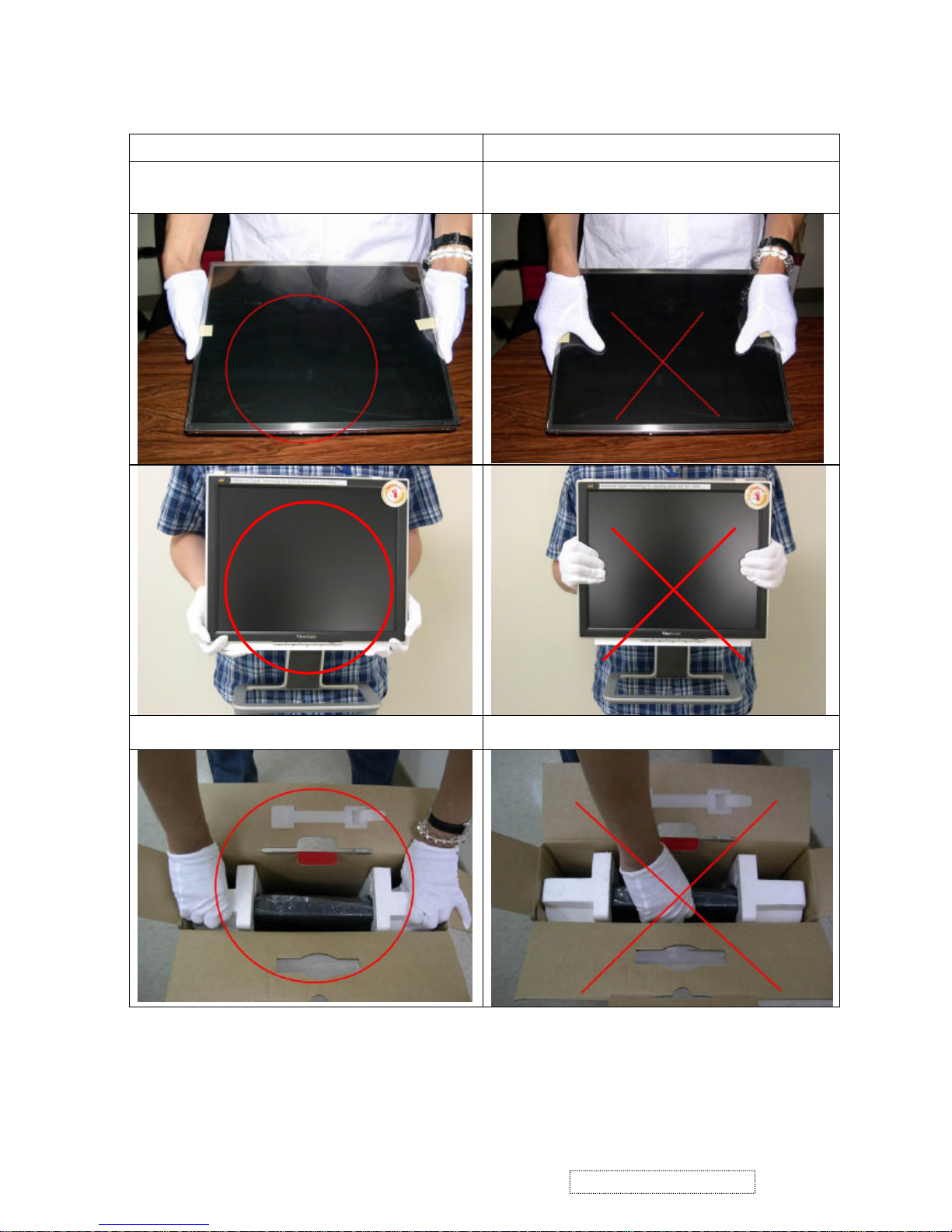
Correct methods : Incorrect Methods :
Only touch the metal frame of the panel or the front
cover of the monitor.
Do not touch the surface of the polarizer .
If the surface of the panel is pressed by fingers, this
may cause "MURA."
Take out the monitor by grasping the cushion. If the monitor is removed by grasping the LCD
panel, that may cause "MURA."
3
ViewSonic Corporation Confidential
-
Do Not Copy VX710
5. Handling Methods
Page 7
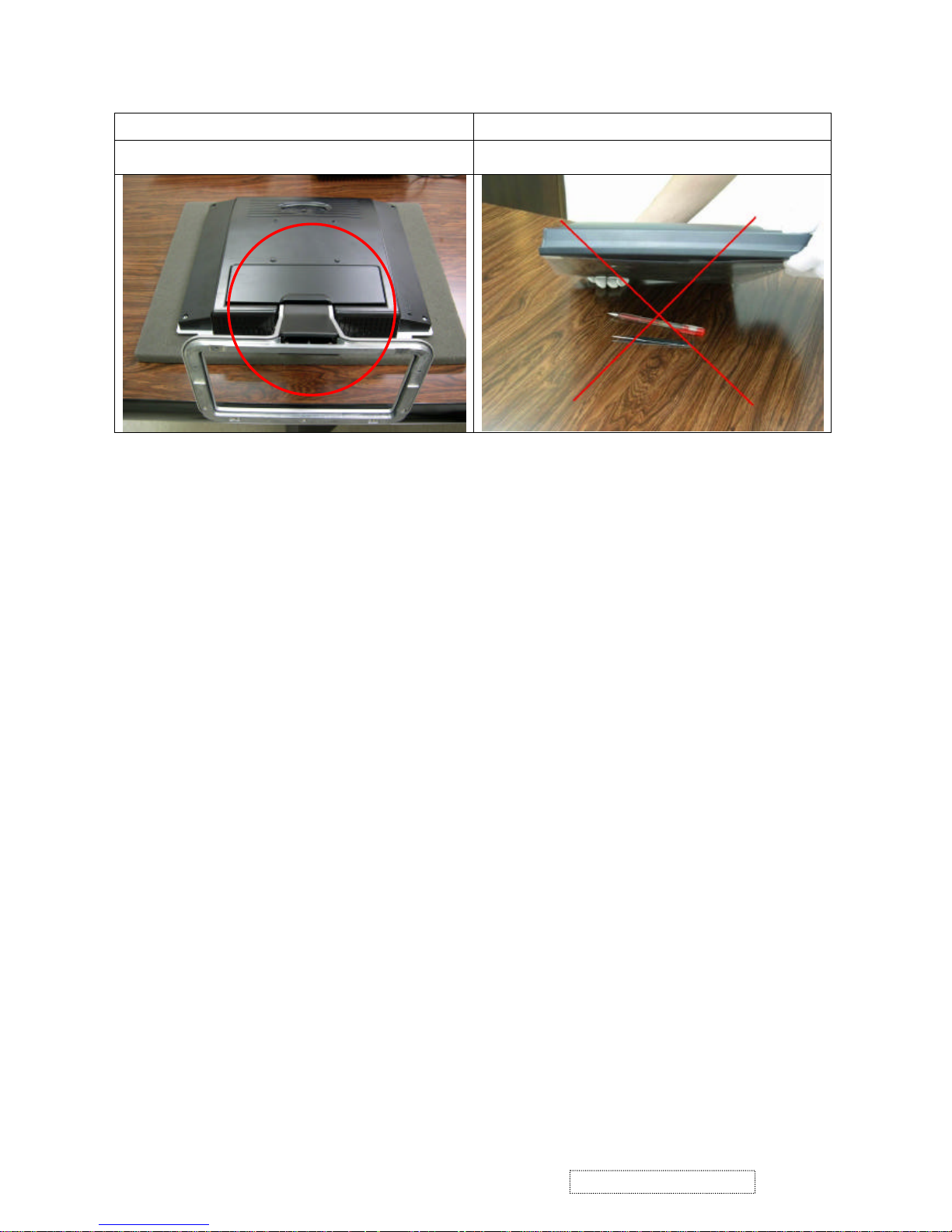
Correct Methods : Incorrect Methods :
Place the monitor on a clean & soft foam pad . If the monitor is placed on foreign objects,
that could scratch the surface of the panel.
4
ViewSonic Corporation Confidential
-
Do Not Copy VX710
Page 8
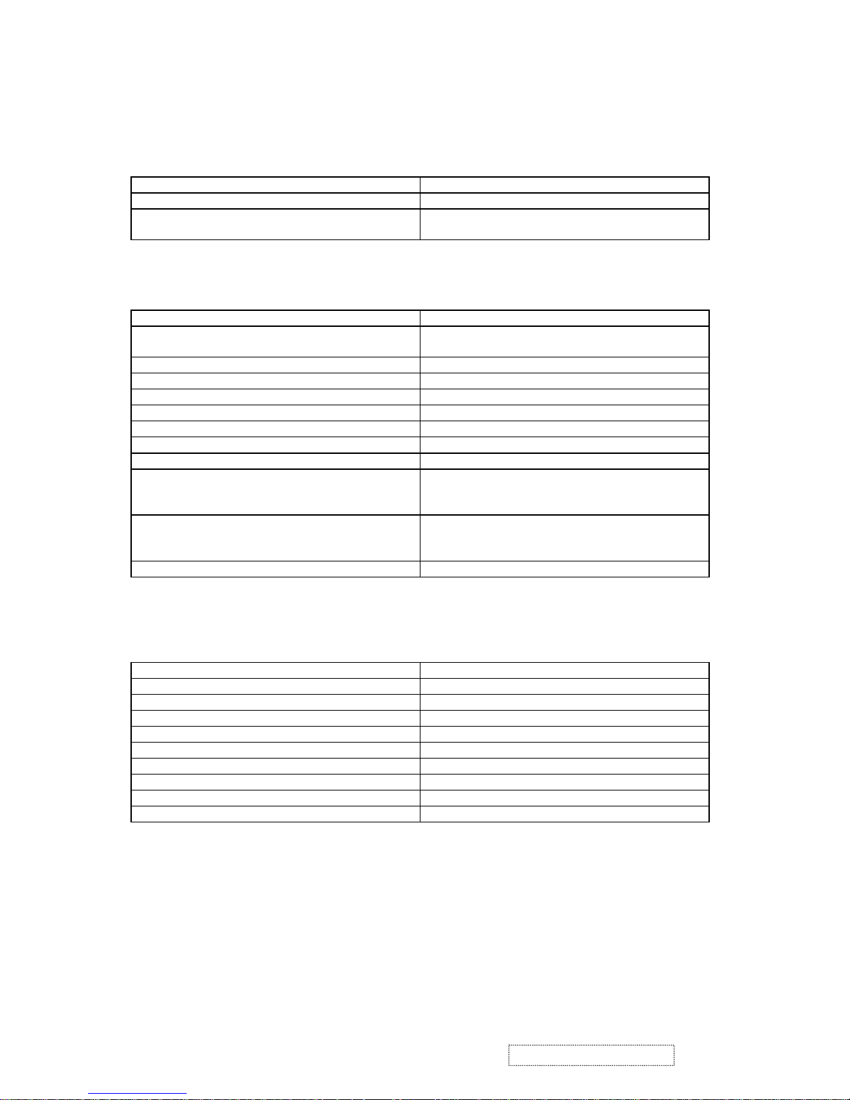
2.1. GENERAL REQUIREMENTS
General Specifications
Test Resolution & Frequency 1280 x 1024 @ 60Hz
Test Image Size Full Size
Contrast and Brightness Controls Factory Default: Contrast = 70%, Brightness =
100%
2.2 SIGNAL INTERFACE
Video Interface
Analog Input Connector DB-15 (Analog)
Video Cable Strain Relief Equal to twice the weight of the monitor for five
minutes.
Video Cable Connector DB-15 Pinout Compliant DDC 2B.
Video Signals Video RGB (Analog)
Video Impedance 75 Ohms (Analog)
Maximum PC Video Signal 950 mV with no damage to monitor
Maximum Mac Video Signal 1250 mV with no damage to monitor
Sync Signals TTL
DDC 1/2B Compliant with Revision 1.3
Video Compatibility Shall be compatible with all PC type computers,
Macintosh computers, and after market video
cards.
Resolution Compatibility 640 x 350, 640 x 480, 720 x 400 (640 x 400), 800 x
600, 832 x 624, 1024 x 768, 1280 x 720, 1280 x
1024
Exclusions Not compatible with interlaced video.
2.3. POWER
Power Supply
Internal Power Supply Part Number: / FSP035-1PI01
Input Voltage Range 90 TO 264 VAC
Input Frequency Range 47.5 TO 63 HERTZ
Short Circuit Protection Output can be shorted without damage.
Over Current Protection 4.5 A typical at 12 VDC
Leakage Current 3.5mA (Max) at 254VAC / 60Hz
EFFICIENCY 70 % typical at 115VAC Full Load
Fuse Internal and not user replaceable
Power Dissipation 35 Watts (typ)
Max Input AC Current 1.2 Arms @ 90VAC, 0.8 Arms @180VAC
2. Specification
5
ViewSonic Corporation Confidential
-
Do Not Copy VX710
Page 9
2.4. ELECTRICAL REQUIREMENTS
Horizontal / Vertical Frequency
Horizontal Frequency 30 – 82 KHZ
Vertical Refresh Rate 50 –85 HZ.
Maximum Pixel Clock 135 MHz
Sync Polarity Independent of sync polarity.
Primary Presets
Primary Preset 1280 x 1024 @ 60Hz
Look up table timing
<<Analog>>
1. 640 x 350 @ 70Hz, 31.5kHz
2. 640 x 480 @ 60Hz, 31.5kHz
3. 640 x 480 @ 67Hz, 35.0kHz
4. 640 x 480 @ 75Hz, 37.5kHz
5. 640 x 480 @ 72Hz, 37.9kHz
6. 640 x 480 @ 85Hz, 43.27kHz
7. 720 x 400 @ 70Hz, 31.5kHz
8. 800 x 600 @ 56Hz, 35.1kHz
9. 800 x 600 @ 60Hz, 37.9kHz
10. 800 x 600 @ 75Hz, 46.9kHz
11. 800 x 600 @ 72Hz, 48.1kHz
12. 800 x 600 @ 85Hz, 53.7kHz
13. 832 x 624 @ 75Hz, 49.7kHz
14. 1024 x 768 @ 60Hz, 48.4kHz
15. 1024 x 768 @ 70Hz, 56.5kHz
16. 1024 x 768 @ 72Hz, 58.1kHz
17. 1024 x 768 @ 75Hz, 60.0kHz
18. 1024 x 768 @ 85Hz, 68.67kHz
19. 1280 x 1024 @ 60Hz, 63.4kHz
20. 1280 x 1024 @ 75Hz, 79.97kHz
21. 1280x720 @ 60Hz, 45kHz (HDTV)
Changing Modes
Maximum Mode Change Blank Time, for
image stability. Note:
1) Excluding “Auto Adjust” time
2) Under DOS mode (640 x 350, 720 x 400 & 640 x
400), there is no “Auto Adjust” feature.
3) The monitor needs to do “Auto Adjust” the first
time a new mode is detected.
3 seconds (Max)
1 seconds (Typ) for recognized timings
1-2 seconds (Typ) for unrecognized timing
.
Mode Change Image The image shall blank while the monitor changes
modes.
6
ViewSonic Corporation Confidential
-
Do Not Copy VX710
Page 10
2.5. LCD PANEL
1
st
Source Panel
Model number QDI QD170EL0709
Type TN type with LVDS interface
Active Size 337.9 (H) x 270.3 (V)
Pixel Arrangement RGB Vertical Stripe
Pixel Pitch 0.264 mm
GLASS TREATMENT Anti Glare (Hard coating 3H)
# OF BACKLIGHTS 4 CCFL edge-light (2 top / 2 bottom)
BACKLIGHT LIFE 50,000 Hours (Typ) / 40,000 Hours (Min)
Luminance (Center) –
Condition:
CT = 6500K, Contrast = Max, Brightness = Max
260 cd/m2 (Typ after 30 minute warm up)
200 cd/m2 (Min after 30 minute warm up)
Brightness Uniformity Dw = 1.25 (typ), 1.33 (max)
dw = Max luminance (of 9 points)/ Min luminance (of 9
points)
Contrast Ratio 500:1 (typ), 300:1 (min)
Color Depth 16.2 million colors (6+2 bit panel)
Viewing Angle (Horizontal) @ CR>10
Typical: 140º (±70º)
Minimum: 120º (±60º)
@ CR>5
Typical: 160º (±80º)
Minimum: 140º (±70º)
VIEWING ANGLE (VERTICAL) @ CR>10
Typical: 125º
Minimum: 105º
@ CR>5
Typical: 145º
Minimum: 125º
Response Time
10%-90% @ Ta=25°C
8 ms (Tr= 2 ms, Tf = 6 ms) (typ)
16 ms (max)
Panel Defects Please see Panel Quality Specifications.
7
ViewSonic Corporation Confidential
-
Do Not Copy VX710
Page 11
2.6. MECHANICAL
Dimensions (Base attached unless otherwise specified)
Width 377.6 mm
Height 374.0 mm
Depth 195.6 mm
Depth (Head Only) 55.0 mm
Monitor Weight 4.1 kg / 9.0 lbs
Packaging Specification
Width 450 mm
Height 522 mm
Depth 135 mm
Gross Weight 5.2 kg (11.45 lb)
# units per Pallet 36/72 (air/sea)
20’/40’ Container Loading, Palletized 720/1728 pieces
Ergonomics
Tilt Up 20 degrees minimum
Tilt Down -5 degrees
Swivel Right 0 degrees
Swivel Left 0 degrees
Height Adjust 0 mm
Pivot 0 degrees (Clockwise)
2.7. ENVIRONMENTAL
Environmental Conditions
Operating Temperature 0°C to +40°C
Storage Temperature -20°C to +60°C
Operating Relative Humidity 20% to 90% RH Non-Condensing
Storage Relative Humidity 5% to 90% RH Non-Condensing
Operating Altitude 0 to +3,000 meters
Storage Altitude 0 to +12,000 meters
8
ViewSonic Corporation Confidential
-
Do Not Copy VX710
Page 12
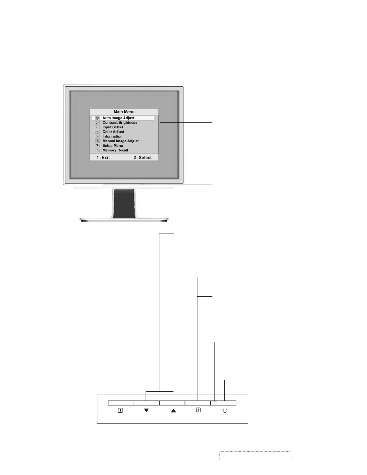
Adjusting the Screen Image
Use the buttons on the front control panel to display and adjust the OnView® controls which
display on the screen. The OnView controls are explained at the top of the next page.
Main Menu
with OnView controls
Front Control Panel
shown below in detail
Scrolls through menu options and adjusts the
displayed control.
Also a shortcut to display the Contrast adjustment
control screen.
Displays the control screen for the
highlighted control.
Also toggles between two controls on
some screens.
Also a shortcut to toggle analog and
digital connection.
Power light
Green = ON
Orange = Power Saving
Standby Power On/Off
Displays the Main
Menu or exits the
control screen
and saves
adjustments.
3. Front Panel Function Control Description
9
ViewSonic Corporation Confidential
-
Do Not Copy VX710
Page 13
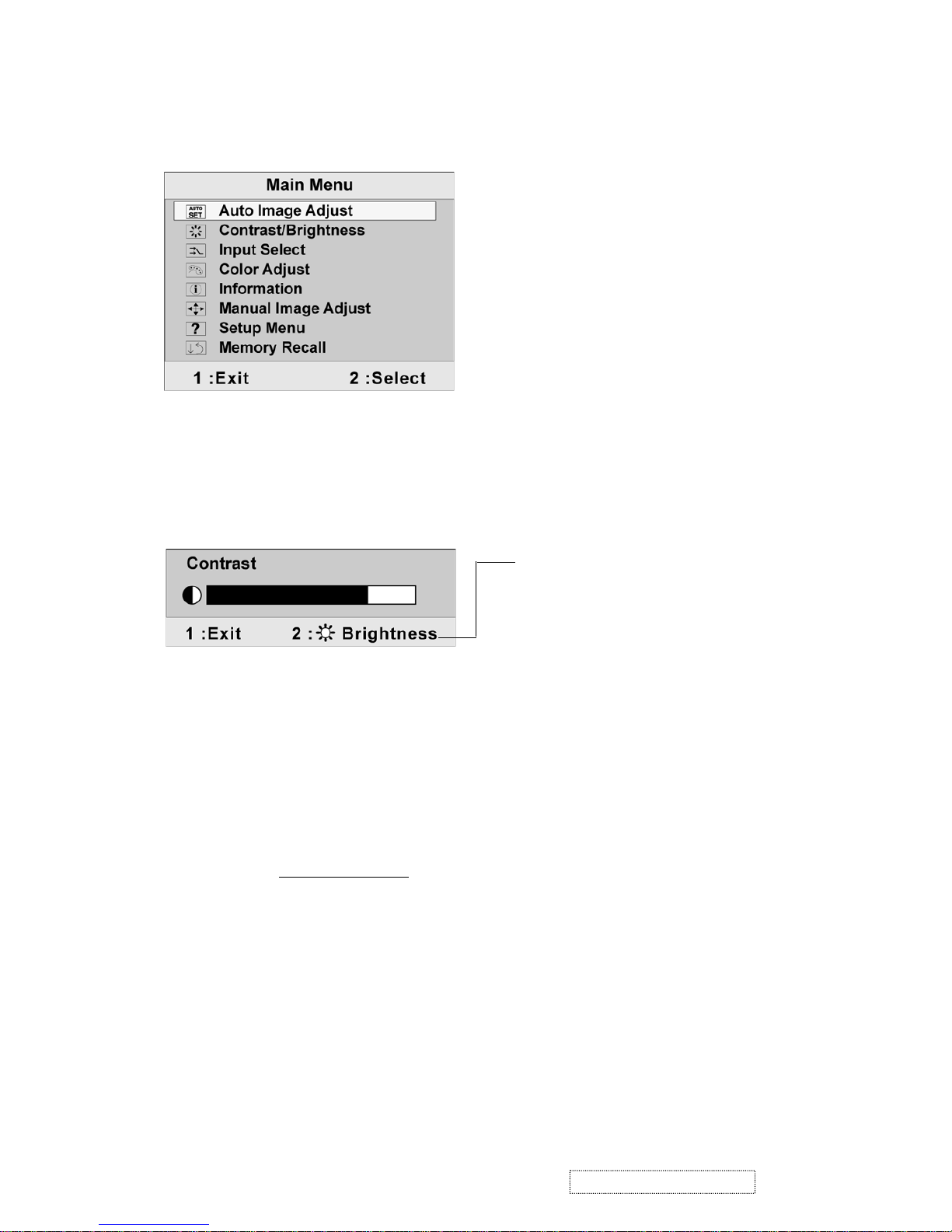
Do the following to adjust the screen image:
1. To display the Main Menu, press button [1].
NOTE: All OnView menus and adjustment screens disappear automatically after about 30
seconds. This is adjustable through the OSD timeout setting in the setup menu.
2. To select a control you want to adjust, pressSorTto scroll up or down the Main Menu.
3. After the control is selected, press button [2]. A control screen like the one shown below
appears.
4. To adjust the control, press the upSor downTbuttons.
5. To save the adjustments and exit the menu, press button [1] twice.
The following tips may help you optimize your display:
• Adjust your computer's graphic card so that it outputs a video signal 1280 x 1024 @ 60Hz
to the LCD display. (Look for instructions on “changing the refresh rate” in your graphic
card's user guide.)
• If necessary, make small adjustments using H. POSITION and V. POSITION until the
screen image is completely visible. (The black border around the edge of the screen should
barely touch the illuminated “active area” of the LCD display.)
The line at the bottom of the screen shows the
current functions of buttons 1 and 2: Exit or select
the Brightness control.
10
ViewSonic Corporation Confidential
-
Do Not Copy VX710
Page 14
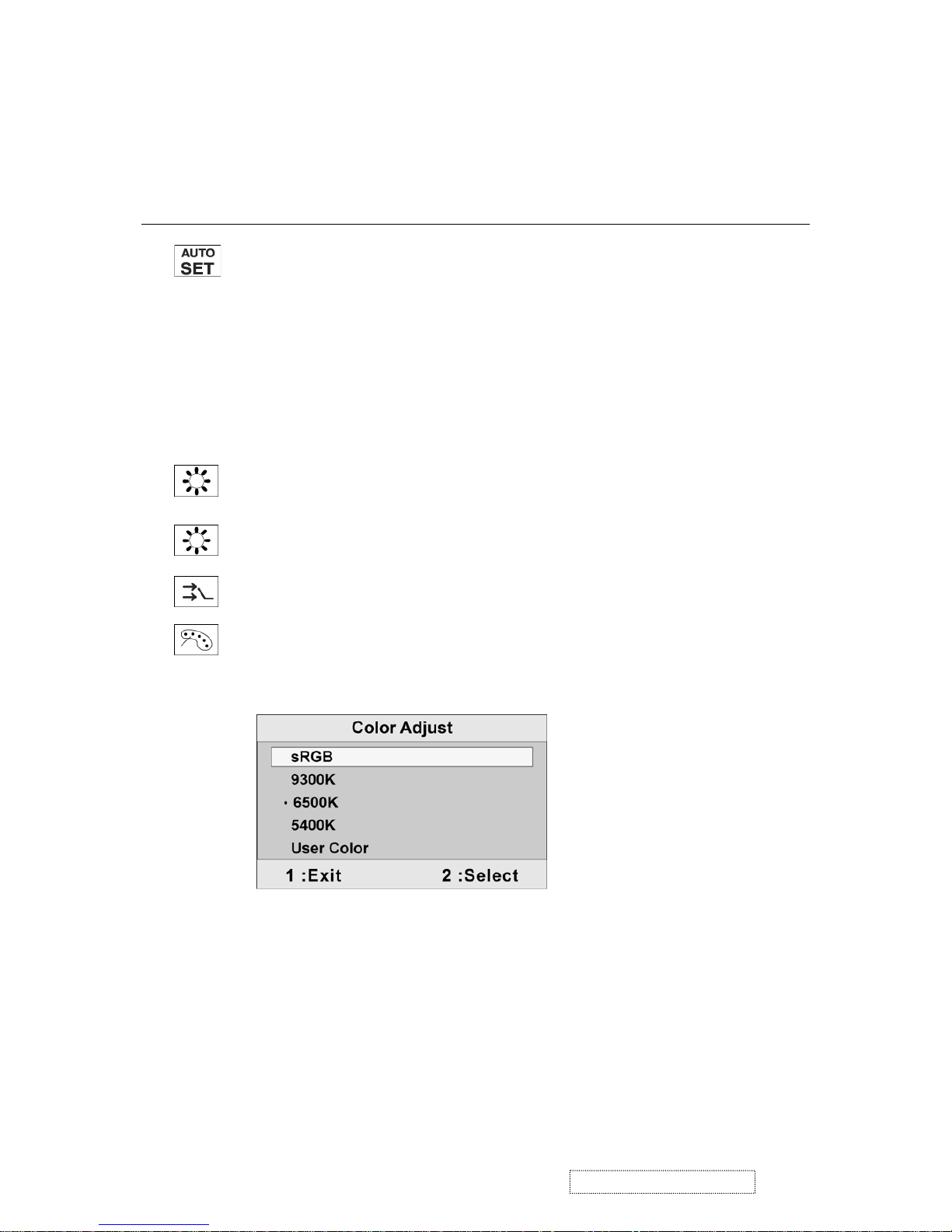
Main Menu Controls
Adjust the menu items shown below by using the upSand downTbuttons.
Control Explanation
Auto Image Adjust automatically sizes, centers, and fine tunes the video signal
to eliminate waviness and distortion. Press the [2] button to execute the Auto Image
Adjust function.
NOTE:
1. Auto Image Adjust works with most common video cards. If this function
does not work on your LCD display, then lower the video refresh rate to 60
Hz and set the resolution to its pre-set value.
2. The Auto Image Adjust and most Manual Image Adjust functions are not
available for DVI input.
Contrast adjusts the difference between the image background (black level)
and the foreground (white level).
Brightness adjusts background black level of the screen image.
Input Select toggles between analog and digital input signals.
sRGB-RGB is quickly becoming the industry standard for color management,
with support being included in many of the latest applications. Enabling this
setting allows the LCD display to more accurately display colors the way they
were originally intended. Enabling the sRGB setting will cause the Contrast and
Brightness adjustments to be disabled.
9300K-Adds blue to the screen image for cooler white (used in most office
settings with fluorescent lighting).
6500K-Adds red to the screen image for warmer white and richer red.
5400K-Adds green to the screen image for a darker color.
Color Adjust provides several color options, including preset color
temperatures and RGB mode which allows the red (R), green
(G), and blue (B) levels to be adjusted independently. The factory
setting for this
product is 6500K (6500 Kelvin).
11
ViewSonic Corporation Confidential
-
Do Not Copy VX710
Page 15
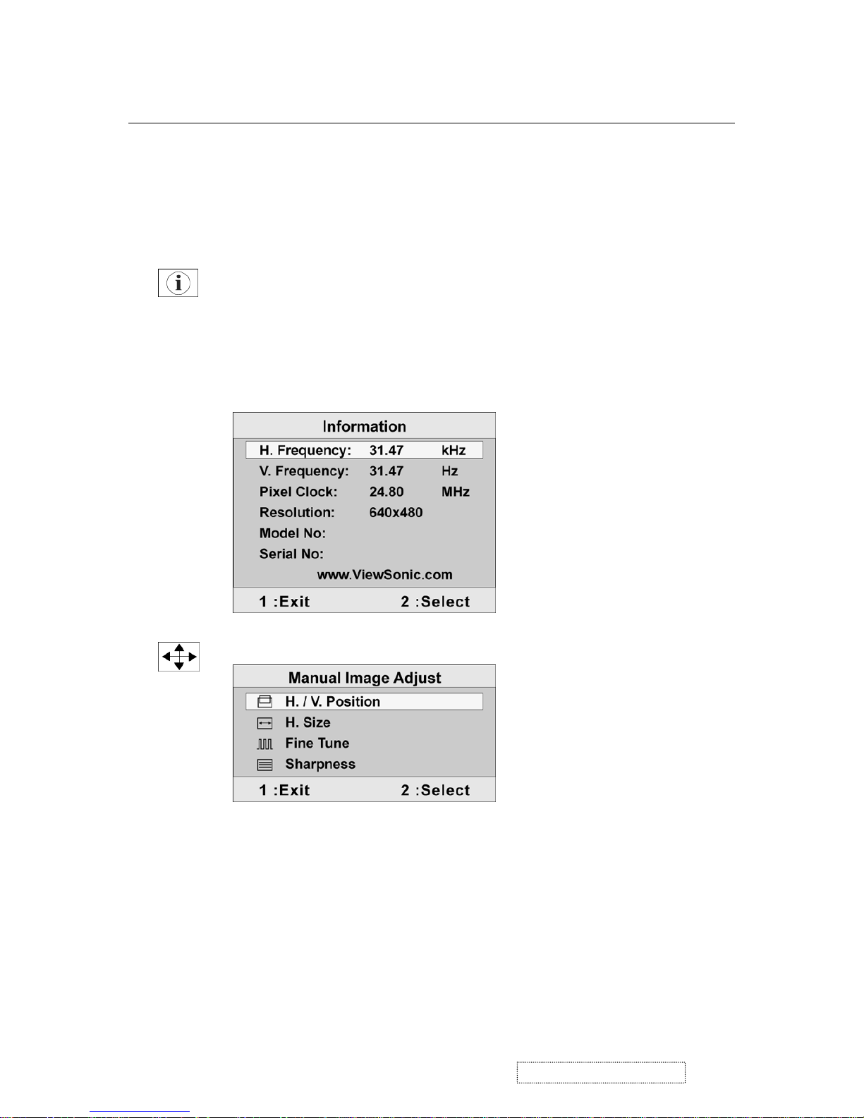
Control Explanation
User Color Individual adjustments for red (R), green (G), and blue (B).
1. To select color (R, G or B) press button [2].
2. To adjust selected color, pressSorT.
Important: If you select RECALL from the Main Menu when the product is set
to a Preset Timing Mode, colors return to the 6500K factory preset.
Manual Image Adjust displays the Manual Image Adjust menu.
Information
displays the timing mode (video signal input)
coming from the graphics card in your computer. See your
graphic card’s user guide for instructions on changing the
resolution and refresh rate (vertical frequency).
NOTE:
VESA 1280 x 1024 @ 60 Hz (recommended) means
that the resolution is 1280 x 1024 a
nd t
he refresh rate is 60
Hertz.
The
Manual Image Adjust
controls are explained below:
Horizontal Size
adjusts the width of the screen image.
Horizontal Position
moves the screen image left or right.
Vertical Position
moves the screen image up or down.
Fine Tune
sharpens the focus by aligning text and graphics with
display pixels.
Sharpness
adjusts the clarity and focus of the screen image.
12
ViewSonic Corporation Confidential
-
Do Not Copy VX710
Page 16
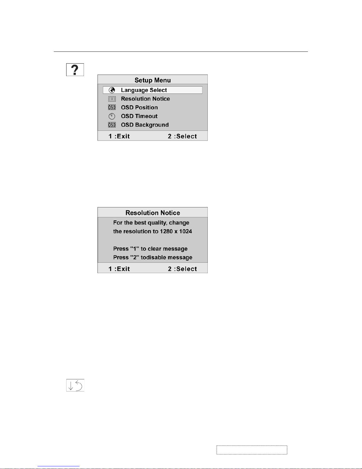
Control Explanation
Setup menu displays the menu shown below:
The Setup Menu controls are explained below:
Language allows the user to choose the language used in the
menus and control screens.
Resolution Notice displays the Resolution Notice menu shown below.
Resolution Notice advises the optimal resolution to use.
OSD Position allows the user to move the on-screen display
menus and control screens.
OSD Timeout
se
ts the length of time an on-screen display
screen is displayed. For example, with a “15 second” setting, if
a control is not pushed within 15 seconds, the display screen
disappears.
OSD Background
allows the user to turn the On-Screen-Display
background on or off.
Memory Recall
returns adjustments to the original factory
settings if the display is operating in a factory Preset Timing
Mode listed in this user guide.
Exception:
This control does not affect changes made with the
User Color control, Language and Power Lock setting.
13
ViewSonic Corporation Confidential
-
Do Not Copy VX710
Page 17
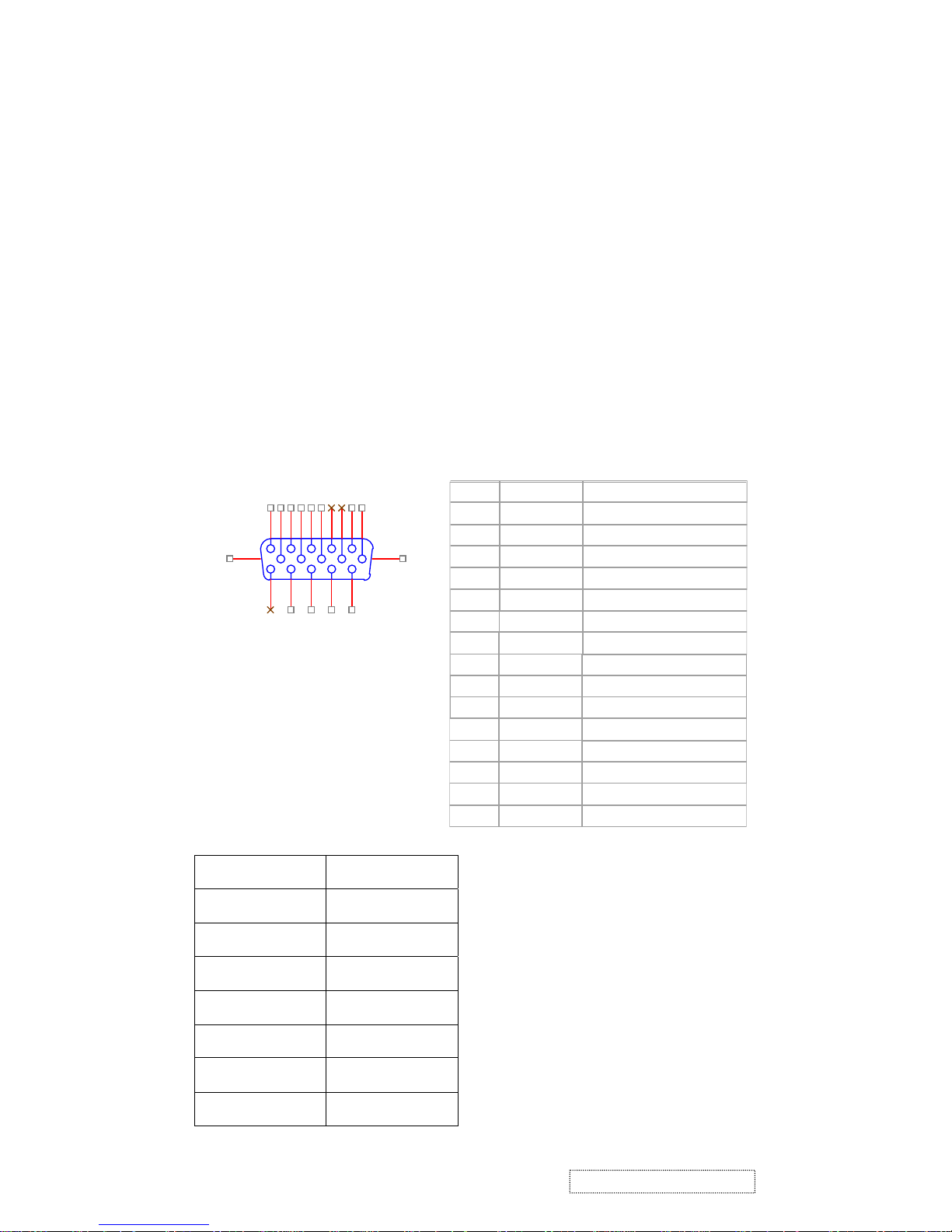
1. Outline
1.2 Video signal connector and AC-IN are located on the back side of the cabinet.
1.3 OSD menu includes the following function;
2. Connectors
CN6
DB15HD
1
6
2
7
3
8
4
9
5
11
12
13
14
15
10
16
17
PIN MNEMONIC SIGNA
L
1 RV
Red Video
2 GV
Gree n Video
3 BV
Blue Video
4
N
C
N
one
5 GND
Ground(DDC return
)
6 RG
Red GND
7 GG
Gree n GND
8 BG
Blue GND
9 +5V
+ 5V (for DDC
)
10 SG
Sync GND
11
N
C
N
one
12 SD
A
DDC Data
13 HS
Horizontal Sync
14 VS
Vertical Sync
15 SC
L
DDC Cloc
k
4. Circuit Description
3. Electrical Specifications
3.1 Standard conditions
Display Area
338 x 270 mm
Video Signal
0.7 Vpp
Contrast
70%
Brightness
Max.
Ambient
20 +/- 5 °C
Input
AC
Warming up
> 30 min
Display
1280 x 1024
2.1
AC Socket: CEE22 type connector
2.2 Video signal connector for analog input: 15P Mini D-Sub
Auto Image Adjust (only active under analog input)
Contrast/Brightness
Audio Adjust
Color Adjust
Information
Manual Image Adjust
Setup Menu
Memory Recall
1.4
Contrast and Brightness can be directly controlled with the UP / DOWN buttons.
1.1 Buttons on the front panel: Power On/Off button, button 2 (ENTER / INPUT SELECT), up arrow
button, down arrow button, button 1 (MENU).
14
ViewSonic Corporation Confidential
-
Do Not Copy VX710
Page 18
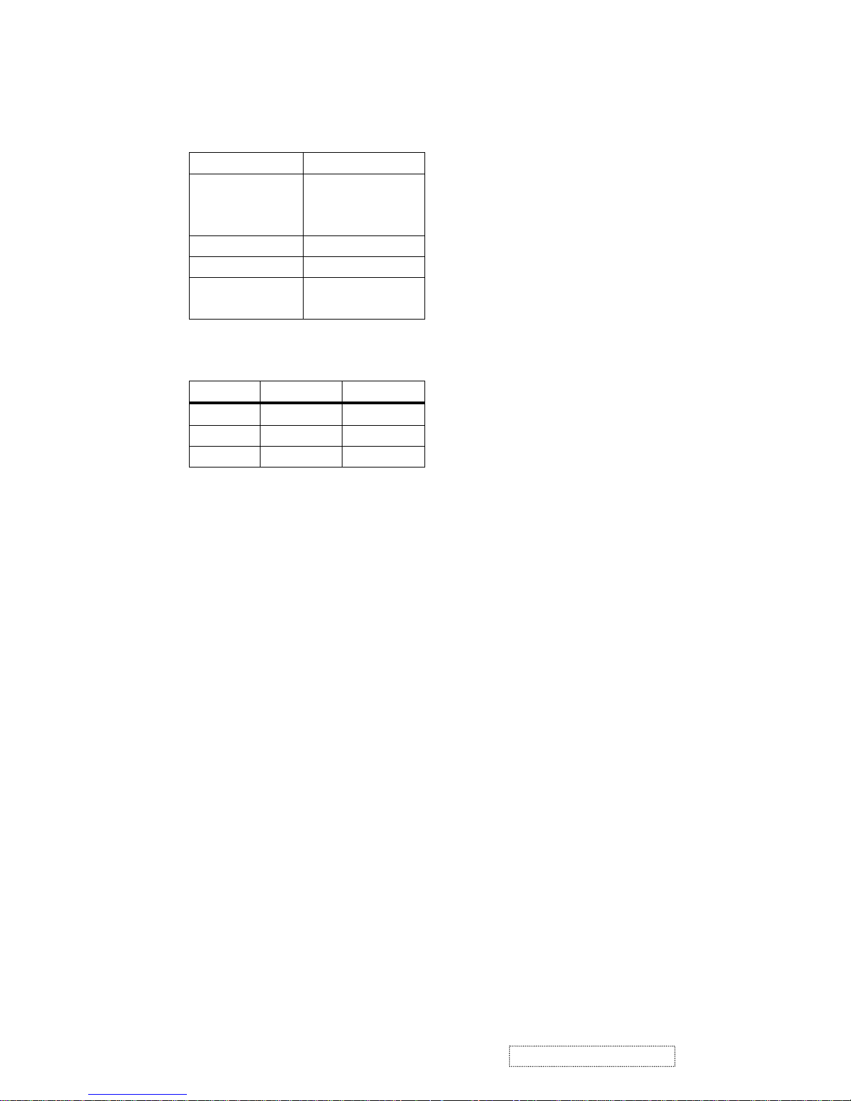
3.2 Power
3.2.1 Power supply
Input Voltage 90 -240 ~Volts
Power Frequency
Input current
50/ 60 Hz +/-3Hz
<1.5Arms @ 90Vac
<0.75Arms@240Vac
Inrush current 90A(max.) at 230Vac
Power consumption 50Watt
Output Voltage @0-3.0A load 12Vdc
+/-5%
3.2.2 Power Management
State Power Indicator
On 40Watt Green
Standby <1Watt Amber
Off <1Watt
3.3 Acceptable timing
Horizontal: Sync frequency : 30~81 kHz
Vertical: Sync frequency : 56~85Hz(1280x1024,75Hz)
3.4 Signal level and input impedance
3.4.1 Video Signal level This LCD display is adjusted at the factory using 0,7 Vp-p Video signal.
3.4.2 Sync Signal level
H/V Separate : TTL level
3.4.3 Input impedance
Video input : 75 ohms
Sync input : > 1 k ohms
4. SIGNAL CABLE :
Signal cable with Mini D-Sub 15P connectors at both ends. Length : 1.8 meter.
This LCD display can automatically detect and display input signals whose timing falls within the
following limits.
15
ViewSonic Corporation Confidential
-
Do Not Copy VX710
Page 19

5. EDID data
Analog EDID
QDI Panel
Time: 16:20:59
Date: Wed Feb 02, 2005
______________________________________________________________________
VIEWSONIC CORPORATION
EDID Version # 1, Revision # 3
DDCTest For: ViewSonic VX710
______________________________________________________________________
EDID Block 0, Bytes 0-127
128 BYTES OF EDID CODE:
0 1 2 3 4 5 6 7 8 9
________________________________________
0 | 00 FF FF FF FF FF FF 00 5A 63
10 | 19 3B 01 01 01 01 01 0F 01 03
20 | 0E 22 1B 78 2E 8A 15 A3 58 49
30 | 9D 24 16 50 54 BF EF 80 81 80
40 | 71 4F 61 59 45 59 31 59 01 01
50 | 01 01 01 01 30 2A 00 98 51 00
60 | 2A 40 30 70 13 00 52 0E 11 00
70 | 00 1E 00 00 00 FF 00 50 31 53
80 | 30 35 30 31 30 30 30 30 31 0A
90 | 00 00 00 FD 00 32 55 1E 52 0E
100 | 00 0A 20 20 20 20 20 20 00 00
110 | 00 FC 00 56 58 37 31 30 0A 20
120 | 20 20 20 20 20 20 00 3C
______________________________________________________________________
(08-09) ID Manufacturer Name = VSC
(11-10) Product ID Code = 3B19
(12-15) Last 5 Digits of Serial Number = Not Used
(16) Week of Manufacture = 01
(17) Year of Manufacture = 2005
(10-17) Complete Serial Number = See Descriptor Block
(18) EDID Version Number = 1
(19) EDID Revision Number = 3
(20) VIDEO INPUT DEFINITION:
Analog Signal
0.700, 0.300 (1.000 Vp-p)
Separate Syncs, Composite Sync, Sync on Green
(21) Maximum Horizontal Image Size = 340 mm
(22) Maximum Vertical Image Size = 270 mm
(23) Display Gamma = 2.20
(24) Power Management and Supported Feature(s):
Active Off/Very Low Power, Standard Default Color Space,
Preferred Timing Mode
Display Type = R/G/B Color
16
ViewSonic Corporation Confidential
-
Do Not Copy VX710
Page 20

(25-34) CHROMA INFO:
Red X - 0.639 Green X - 0.287 Blue X - 0.141 White X - 0.313
Red Y - 0.344 Green Y - 0.615 Blue Y - 0.087 White Y - 0.329
(35) ESTABLISHED TIMING I:
720 X 400 @ 70Hz (IBM,VGA)
640 X 480 @ 60Hz (IBM,VGA)
640 X 480 @ 67Hz (Apple,Mac II)
640 X 480 @ 72Hz (VESA)
640 X 480 @ 75Hz (VESA)
800 X 600 @ 56Hz (VESA)
800 X 600 @ 60Hz (VESA)
(36) ESTABLISHED TIMING II:
800 X 600 @ 72Hz (VESA)
800 X 600 @ 75Hz (VESA)
832 X 624 @ 75Hz (Apple,Mac II)
1024 X 768 @ 60Hz (VESA)
1024 X 768 @ 70Hz (VESA)
1024 X 768 @ 75Hz (VESA)
1280 X 1024 @ 75Hz (VESA)
(37) Manufacturer's Reserved Timing:
1152 X 870 @ 75Hz (Apple,Mac II)
(38-53) Standard Timing Identification:
1280 X 1024 @60Hz
1152 X 864 @75Hz
1024 X 768 @85Hz
800 X 600 @85Hz
640 X 480 @85Hz
Not Used
Not Used
Not Used
______________________________________________________________________
(54-71) Detailed Timing / Descriptor Block 1:
1280x1024 Pixel Clock: 108.00 MHz
______________________________________________________________________
Horizontal Image Size: 338 mm Vertical Image Size: 270 mm
Refreshed Mode: Non-Interlaced Normal Display - No Stereo
Horizontal:
Active Time: 1280 pixels Blanking Time: 408 pixels
Sync Offset: 48 pixels Sync Pulse Width: 112 pixels
Border: 0 pixels Frequency: 63.98 KHz
Vertical:
Active Time: 1024 lines Blanking Time: 42 lines
Sync Offset: 1 lines Sync Pulse Width: 3 lines
Border: 0 lines Frequency: 60.02 Hz
Digital Separate, Horizontal Polarity (+) Vertical Polarity (+)
______________________________________________________________________
17
ViewSonic Corporation Confidential
-
Do Not Copy VX710
Page 21

(72-89) Detailed Timing / Descriptor Block 2:
Monitor Serial Number:
P1S050100001
______________________________________________________________________
(90-107) Detailed Timing / Descriptor Block 3:
Monitor Range Limits:
Min Vertical Freq - 50 Hz
Max Vertical Freq - 85 Hz
Min Horiz. Freq - 30 KHz
Max Horiz. Freq - 82 KHz
Pixel Clock - 140 MHz
Secondary GTF - Not Supported
______________________________________________________________________
(108-125) Detailed Timing / Descriptor Block 4:
Monitor Name:
VX710
(126) No Extension EDID Block(s)
(127) CheckSum OK
18
ViewSonic Corporation Confidential
-
Do Not Copy VX710
Page 22

Digital EDID
TIME: 16:21:22
DATE: WED FEB 02, 2005
______________________________________________________________________
VIEWSONIC CORPORATION
EDID VERSION # 1, REVISION # 3
DDCTEST FOR: VIEWSONIC VX710
______________________________________________________________________
EDID BLOCK 0, BYTES 0-127
128 BYTES OF EDID CODE:
0 1 2 3 4 5 6 7 8 9
________________________________________
0 | 00 FF FF FF FF FF FF 00 5A 63
10 | 19 3B 01 01 01 01 01 0F 01 03
20 | 80 22 1B 78 2E 8A 15 A3 58 49
30 | 9D 24 16 50 54 BF EF 80 81 80
40 | 71 4F 61 59 45 59 31 59 31 0A
50 | 01 01 01 01 30 2A 00 98 51 00
60 | 2A 40 30 70 13 00 52 0E 11 00
70 | 00 1E 00 00 00 FF 00 50 31 53
80 | 30 35 30 31 30 30 30 30 31 0A
90 | 00 00 00 FD 00 32 55 1E 52 0E
100 | 00 0A 20 20 20 20 20 20 00 00
110 | 00 FC 00 56 58 37 31 30 0A 20
120 | 20 20 20 20 20 20 00 91
______________________________________________________________________
(08-09) ID MANUFACTURER NAME = VSC
(11-10) PRODUCT ID CODE = 3B19
(12-15) LAST 5 DIGITS OF SERIAL NUMBER = NOT USED
(16) WEEK OF MANUFACTURE = 01
(17) YEAR OF MANUFACTURE = 2005
(10-17) COMPLETE SERIAL NUMBER = SEE DESCRIPTOR BLOCK
(18) EDID VERSION NUMBER = 1
(19) EDID REVISION NUMBER = 3
(20) VIDEO INPUT DEFINITION:
DIGITAL SIGNAL
NON - VESA DFP 1.X COMPATIBLE
(21) MAXIMUM HORIZONTAL IMAGE SIZE = 340 MM
(22) MAXIMUM VERTICAL IMAGE SIZE = 270 MM
(23) DISPLAY GAMMA = 2.20
(24) POWER MANAGEMENT AND SUPPORTED FEATURE(S):
ACTIVE OFF/VERY LOW POWER, STANDARD DEFAULT COLOR SPACE,
PREFERRED TIMING MODE
DISPLAY TYPE = R/G/B COLOR
(25-34) CHROMA INFO:
RED X - 0.639 GREEN X - 0.287 BLUE X - 0.141 WHITE X - 0.313
RED Y - 0.344 GREEN Y - 0.615 BLUE Y - 0.087 WHITE Y - 0.329
19
ViewSonic Corporation Confidential
-
Do Not Copy VX710
Page 23

(35) ESTABLISHED TIMING I:
640 X 480 @ 60HZ (IBM,VGA)
640 X 480 @ 67HZ (APPLE,MAC II)
640 X 480 @ 72HZ (VESA)
640 X 480 @ 75HZ (VESA)
800 X 600 @ 56HZ (VESA)
800 X 600 @ 60HZ (VESA)
(36) ESTABLISHED TIMING II:
800 X 600 @ 72HZ (VESA)
800 X 600 @ 75HZ (VESA)
832 X 624 @ 75HZ (APPLE,MAC II)
1024 X 768 @ 60HZ (VESA)
1024 X 768 @ 70HZ (VESA)
1024 X 768 @ 75HZ (VESA)
1280 X 1024 @ 75HZ (VESA)
(37) MANUFACTURER'S RESERVED TIMING:
1152 X 870 @ 75HZ (APPLE,MAC II)
(38-53) STANDARD TIMING IDENTIFICATION:
1280 X 1024 @60HZ
1152 X 864 @75HZ
1024 X 768 @85HZ
800 X 600 @85HZ
640 X 480 @85HZ
640 X 400 @70HZ
NOT USED
NOT USED
______________________________________________________________________
(54-71) DETAILED TIMING / DESCRIPTOR BLOCK 1:
1280X1024 PIXEL CLOCK: 108.00 MHZ
______________________________________________________________________
HORIZONTAL IMAGE SIZE: 338 MM VERTICAL IMAGE SIZE: 270 MM
REFRESHED MODE: NON-INTERLACED NORMAL DISPLAY - NO STEREO
HORIZONTAL:
ACTIVE TIME: 1280 PIXELS BLANKING TIME: 408 PIXELS
SYNC OFFSET: 48 PIXELS SYNC PULSE WIDTH: 112 PIXELS
BORDER: 0 PIXELS FREQUENCY: 63.98 KHZ
VERTICAL:
ACTIVE TIME: 1024 LINES BLANKING TIME: 42 LINES
SYNC OFFSET: 1 LINES SYNC PULSE WIDTH: 3 LINES
BORDER: 0 LINES FREQUENCY: 60.02 HZ
DIGITAL SEPARATE, HORIZONTAL POLARITY (+) VERTICAL POLARITY (+)
______________________________________________________________________
20
ViewSonic Corporation Confidential
-
Do Not Copy VX710
Page 24

MONITOR SERIAL NUMBER:
P1S050100001
______________________________________________________________________
(90-107) DETAILED TIMING / DESCRIPTOR BLOCK 3:
MONITOR RANGE LIMITS:
MIN VERTICAL FREQ - 50 HZ
MAX VERTICAL FREQ - 85 HZ
MIN HORIZ. FREQ - 30 KHZ
MAX HORIZ. FREQ - 82 KHZ
PIXEL CLOCK - 140 MHZ
SECONDARY GTF - NOT SUPPORTED
______________________________________________________________________
(108-125) DETAILED TIMING / DESCRIPTOR BLOCK 4:
MONITOR NAME:
VX710
(126) NO EXTENSION EDID BLOCK(S)
(127) CHECKSUM OK
(72-89) DETAILED TIMING / DESCRIPTOR BLOCK 2:
21
ViewSonic Corporation Confidential
-
Do Not Copy VX710
Page 25
6. THEORY OF OPERATION
This section describes the function of the LCD monitor per functional block.
This monitor includes MB board, power board and button board.
6.1 MB BOARD
The MB board is a two-layer, single-grounded design with ground and internal planes provided. DC power from
the power board enters the board through a 6P connector. The other connector on the board is for the button board.
The VGA cable is a signal cable that carries the video, sync and DDC signals from the PC VGA adapter. This
system board consists of 4 functional areas: flat panel controller, MCU with flash ROM, and power regulators.
6.1.1 Flat panel controller: RTD2523(U7)
The heart of the system board is the Realtek RTD2523. The RTD2523 is a graphics processing IC
designed for LCD monitors. It provides all key IC functions required for LCD displays. On-chip
functions include a high-speed triple-ADC, PLL, high scaling engine and OSD controller.
a) Clock Generation:
Crystal Input Clock (TCLK and XTAL). This is the input pair to an internal crystal oscillator and
corresponding logic. A 24.576 MHz crystal is recommended.
b) Analog to Digital Converter:
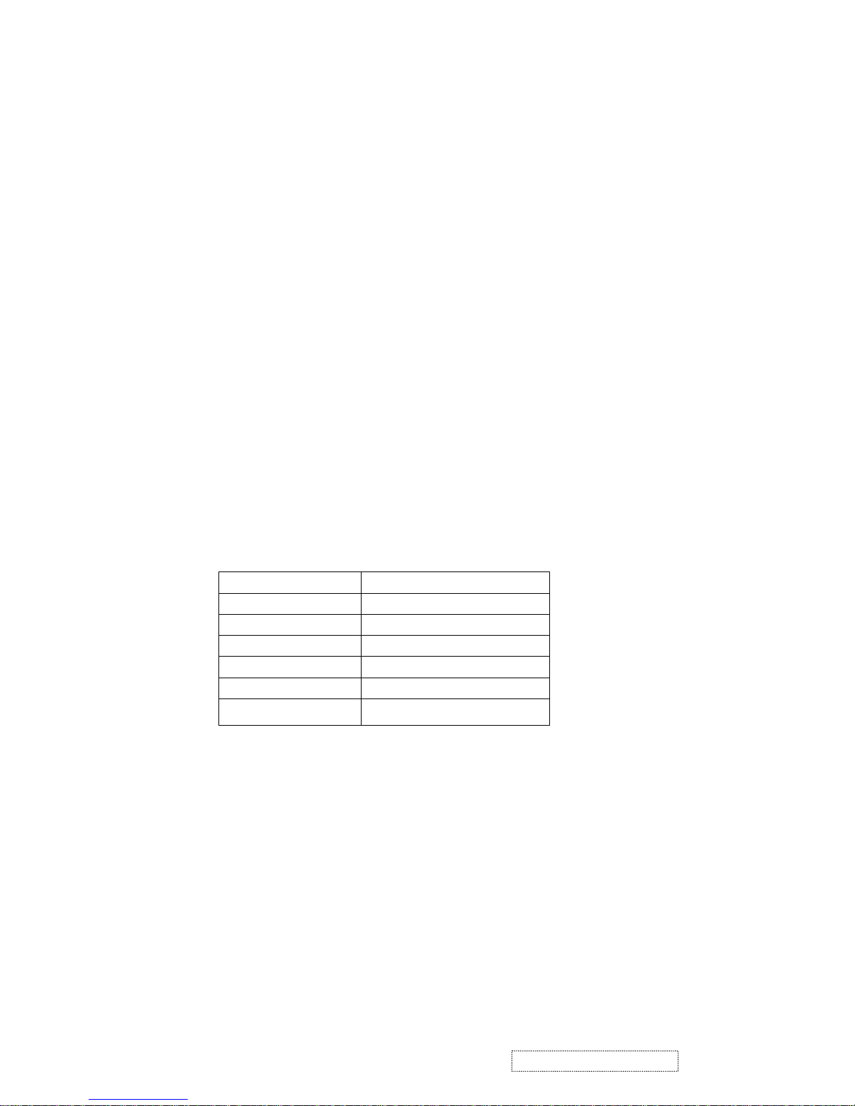
The RTD2523 chip has three ADCs (analog-to-digital converters), one for each color (red, green and blue).
The analog RGB signals are connected to RTD2523 as described below.
Pin Name Pin Number
Red + 37
Red - 38
Green + 34
Green - 35
Blue + 30
Blue - 31
c) OSD: The RTD2523 has a fully programmable, high-quality OSD controller. The on-chip static
RAM (4096 words by 24 bits) stores the cell map and the cell definitions.
22
ViewSonic Corporation Confidential
-
Do Not Copy VX710
Page 26
17 P1.0 Backlight on / off control
e) Panel Power Sequencing (PANEL_PW12,3) (Pin 16, 18): The MTV312 has two dedicated outputs
VDDCTRL1 and 2 ( Pin32 and Pin3) to control LCD power sequencing once data and control signals
are stable.
f) Panel interface (Pin73~94): The RTD2523 driver interface is highly programmable. It supports dual bus /
dual port for SXGA drive rs.
6.1.2 Power Regulator AIC1563 (U2), AIC1117CY (U1,U3): The AIC1563 is a monolithic control IC
containing the primary functions required for DC to DC converters. The device consists of an internal temperature
compensated reference, a comparator, and a controlled duty cycle oscillator with an active current
sense circuit. The desired output voltage is determined by the equation, Volt = 1.25 (1 + R11 / R12).
In this case, the output voltage is 5 Volts. The AIC1563 is a low dropout positive adjustable
regulator with minimum of 1A output current capability, so it is well suited to serve as a 3.3 V or
2.5 V regulator.
6.1.3 Power Regulator AIC1117CY (U1,U3): The AIC1117CY is a monolithic control IC containing the
primary functions required for DC to DC converters. The device consists of an internal temperature
compensated reference, a comparator, and a controlled duty cycle oscillator with an active current
sense circuit. The desired output voltage is determined by the equation, Volt = 1.25 (1 + R17 / R15).
In this case, the output voltage is 2.5 Volts for panel power.
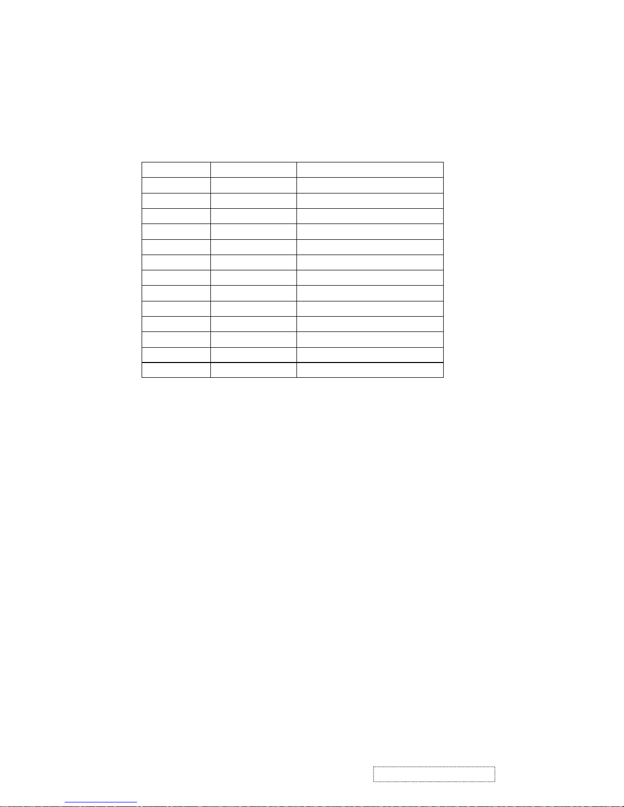
d) MTV312 Micro Controller: The MTV312 micro controller (MCU) serves as the system micro controller.
It programs the RTD2523 and manages other devices in the system such as the keypad, the backlight, the
LED, the audio system and the non-volatile RAM using general purpose input/output (GPIO) pins.
Pin number Pin Name Pin Usage
1 P5.2 Key / Power on, off
13 P3.4 NV_RAM (U4) SDA
14 P3.5 NV_RAM (U4) SCL
41 P5.4 Key_down
40 P5.5 Key_right
42 P5.3 Key_up
34 P5.6 Key_left
9 P6.3 Key_mute
2 P5.1 Key_select
27 P6.0 LED_red
26 P6.1 LED_green
16 P6.2 LCD panel power1 on / off control
23
ViewSonic Corporation Confidential
-
Do Not Copy VX710
Page 27
6.2.2 Power
This is a general purpose AC / DC adapter which converts 90~240 Vac to a stabilized DC voltage: 12
Volts, with a rated output current of 4.16A. The electrical specification is described below.
Rated Input Voltage 90~240 Vac, 50 / 60Hz
Operation Input Voltage 90~260 Vac, 47 ~ 63Hz
Input Current <1.5A
Inrush Current <100A@120Vac
Standby Input Voltage 12Vdc
Output Voltage Regulation +/-5%
Output Ripple & Noise 120mVp-p
Rate Output Current <3.5A
Turn-on delay <3secs
6.2 Power (Inverter) Board
This is a specific power (inverter) board for VX912 monitor with output of 40W / 12V / 3.5A. It provides
12 VDC to drive the four cold cathode fluorescence tubes in the backlight.
6.2.1 The inverter's electrical specification is described below.
Rated Input Voltage 12Vdc
Input Voltage Range 11.4 ~ 12.6 Vdc
Input Current <2A
Input
On / Off control Voltage 2~3.3 for on, 0~1 for off
Rated Output Strike-on Voltage 1500Vrms
Rated Output Voltage 710Vrms at 7mA
Rate Output Frequency 40~50KHz
Output
Rated Output Current 7~8 mA
24
ViewSonic Corporation Confidential
-
Do Not Copy VX710
Page 28

OSD Function Menu
A. When in Analog Input Mode
1. Main Menu
Press the [1] (Menu) button to enter the Main Menu:
Press the [▲] button to highlight the previous item or the [▼] button to highlight
the next item.
Press the [1] (Menu) button to exit the Main Menu.
(1) Auto Image Adjust Page:
Press the [2] button to execute the auto image adjust function.
Press the [1] button to exit the page.
(2) Contrast/Brightness Page:
Press the [2] button to enter the contrast adjustment page.
Press the [1] button to exit the page.
1) Contrast Item
Press the [▲] button to increase the contrast.
Press the [▼] button to decrease the contrast.
Press the [2] button to enter the brightness adjustment page.
Press the [1] button to exit the page.
2) Brightness Item
Press the [▲] button to increase the brightness.
Press the [▼] button to decrease the brightness.
Press the [2] button to enter the contrast adjustment page.
Press the [1] button to exit the page.
(3) Input Select Page:
Press the [2] button to switch to digital input mode.
(4) Color Adjust Page:
Press the [2] button to enter the color adjustment page.
Press the [1] button to exit the page.
Press the [▲] button to highlight the previous item or the [▼] button to
highlight the next item.
1) sRGB Item
2) 9300K Item
3) 6500K Item
4) 5400K Item
Press the [2] button to select the currently highlighted item.
Press the [1] button to exit the currently highlighted item.
5) User Color Item
Press the [2] button to enter the user color page.
Press the [1] button to exit the page.
Red, Green, Blue Options:
Press the [2] button to cycle among the colors.
Press the [1] button to exit the page.
Press the [▲] button to increase the selected color level.
Press the [▼] button to decrease the selected color level.
5. Adjustment Procedure
25
ViewSonic Corporation Confidential
-
Do Not Copy VX710
Page 29

(5) Information Page:
Press the [2] button to enter the information page.
Press the [1] button to exit the information page.
(6) Manual Image Adjust Page:
Press the [2] button to enter the manual image adjustment page.
Press the [1] button to exit the page.
Press the [▲] button to highlight the previous item or the [▼] button to
highlight the next item.
1) H./V. Position Item
Press the [2] button to enter the horizontal/vertical postion adjustment page.
Press the [1] button to exit the page.
a) Horizontal Position:
Press the [2] button to enter the vertical position adjustment page.
Press the [1] button to exit the page.
Press the [▲] button to shift the image to the right.
Press the [▼] button to shift the image to the left.
b) Vertical Position:
Press the [2] button to return to the horizontal position adjustment page.
Press the [1] button to exit the page.
Press the [▲] button to shift the image upward.
Press the [▼] button to shift the image downward.
2) Horizontal Size Item
Press the [2] button to enter the horizontal size adjustment page.
Press the [1] button to exit the page.
Press the [▲] button to make the image wider.
Press the [▼] button to make the image narrower.
3) Fine tune Item
Press the [2] button to enter the fine tuning page.
Press the [1] button to exit the page.
Press “[▲]” Button to adjust character position in one direction.
Press “[▼]“Button to adjust character position in the other direction.
4) Sharpness Item
Press the [2] button to enter the sharpness adjustment page.
Press the [1] button to exit the page.
Press “[▲]” Button to increase image sharpness.
Press “[▼]“ Button to decrease image sharpness.
(7) Setup Menu Page:
Press the [2] button to enter the setup menu page.
Press the [1] button to exit the page.
Press the [▲] button to highlight the previous item or the [▼] button to
highlight the next item.
1) Language Select Item
Press the [2] button to enter the language selection page.
26
ViewSonic Corporation Confidential
-
Do Not Copy VX710
Page 30

Press the [1] button to exit the page.
Press the [▲] button to highlight the previous item or the [▼] button to
highlight the next item.
English, French… Option
Press the [2] button to select the language.
Press the [1] button to exit the page.
2) Resolution Notice Item
Press the [2] button to enter the resolution notice page.
Press the [1] button to exit the page.
Enable, Disable Option
Press the [2] button to select the highlighted option.
Press the [1] button to exit the page.
Press the [▲] button to highlight the previous option or the [▼] button
to highlight the next option.
3) OSD Position Item
Press the [2] button to enter the OSD position adjustment page.
Press the [1] button to exit the page.
a) Horizontal Position Option
Press the [2] button to enter the vertical position adjustment page.
Press the [1] button to exit the page.
Press the [▲] button to shift the menu to the right.
Press the [▼] button to shift the menu to the left.
b) Vertical Position Option:
Press the [2] button to enter the horizontal position adjustment page.
Press the [1] button to exit the page.
Press the [▲] button to shift the menu upward.
Press the [▼] button to shift the menu downward.
4) OSD Time Out Item
Press the [2] button to enter the OSD time out adjustment page.
Press the [1] button to exit the page.
Press the [▲] button to increase the OSD time out.
Press the [▼] button to decrease the OSD time out.
5) OSD Background Item
Press the [2] button to enter the OSD background selection page.
Press the [1] button to exit the page.
Enable, Disable Option
Press the [▲] button to highlight the previous option or the [▼] button
to highlight the next option.
Press the [2] button to select the highlighted option.
Press the [1] button to exit the page.
(8) Memory Recall Page
Press the [2] button to execute the memory recall function.
Press the [1] button to exit the page.
27
ViewSonic Corporation Confidential
-
Do Not Copy VX710
Page 31

2. Other Menu:
This “shortcut” menu is directly accessible without bringing up the OSD.
(1) Contrast Dialog
Press the [▲] or [▼] button to enter the Contrast Dialog.
Press the [1] button to exit the Contrast Dialog.
Press the [2] button to enter the Brightness Dialog.
Press the [▲] button to increase the contrast.
Press the [▼] button to decrease the contrast.
(2) Brightness Dialog
Press the [▲] or [▼] button to enter the Brightness Dialog.
Press the [1] button to exit the Brightness Dialog.
Press the [2] button to enter the Contrast Dialog.
Press the [▲] button to increase the brightness.
Press the [▼] button to decrease the brightness.
(3) Analog/Digital Dialog
Press the [2] button to toggle between analog and digital modes.
B. When in Digital Input Mode
1. Main Menu
Press the [1] (Menu) button to enter the Main Menu:
Press the [▲] button to highlight the previous item or the [▼] button to highlight
the next item.
Press the [1] (Menu) button to exit the Main Menu.
(1) Auto Image Adjust Page:
Press the [2] button to execute the auto image adjust function.
Press the [1] button to exit the page.
(2) Contrast/Brightness Page:
Press the [2] button to enter the contrast adjustment page.
Press the [1] button to exit the page.
1) Contrast Item
Press the [▲] button to increase the contrast.
Press the [▼] button to decrease the contrast.
Press the [2] button to enter the brightness adjustment page.
Press the [1] button to exit the page.
2) Brightness Item
Press the [▲] button to increase the brightness.
Press the [▼] button to decrease the brightness.
Press the [2] button to enter the contrast adjustment page.
Press the [1] button to exit the page.
(3) Input Select Page:
Press the [2] button to switch to analog input mode.
(4) Color Adjust Page:
Press the [2] button to enter the color adjustment page.
28
ViewSonic Corporation Confidential
-
Do Not Copy VX710
Page 32

Press the [1] button to exit the page.
Press the [▲] button to highlight the previous item or the [▼] button to
highlight the next item.
1) sRGB Item
2) 9300K Item
3) 6500K Item
4) 5400K Item
Press the [2] button to select the currently highlighted item.
Press the [1] button to exit the currently highlighted item.
5) User Color Item
Press the [2] button to enter the user color page.
Press the [1] button to exit the page.
Red, Green, Blue Options:
Press the [2] button to cycle among the colors.
Press the [1] button to exit the page.
Press the [▲] button to increase the selected color level.
Press the [▼] button to decrease the selected color level.
(5) Information Page:
Press the [2] button to enter the information page.
Press the [1] button to exit the information page.
(6) Manual Image Adjust Page:
Press the [2] button to enter the manual image adjustment page.
Press the [1] button to exit the page.
Press the [▲] button to highlight the previous item or the [▼] button to
highlight the next item.
1) Sharpness Item
Press the [2] button to enter the sharpness adjustment page.
Press the [1] button to exit the page.
Press “[▲]” Button to increase image sharpness.
Press “[▼]“ Button to decrease image sharpness.
(7) Setup Menu Page:
Press the [2] button to enter the setup menu page.
Press the [1] button to exit the page.
Press the [▲] button to highlight the previous item or the [▼] button to
highlight the next item.
1) Language Select Item
Press the [2] button to enter the language selection page.
Press the [1] button to exit the page.
Press the [▲] button to highlight the previous item or the [▼] button to
highlight the next item.
English, French… Option
Press the [2] button to select the language.
Press the [1] button to exit the page.
2) Resolution Notice Item
Press the [2] button to enter the resolution notice page.
29
ViewSonic Corporation Confidential
-
Do Not Copy VX710
Page 33

Press the [1] button to exit the page.
Enable, Disable Option
Press the [2] button to select the highlighted option.
Press the [1] button to exit the page.
Press the [▲] button to highlight the previous option or the [▼] button
to highlight the next option.
3) OSD Position Item
Press the [2] button to enter the OSD position adjustment page.
Press the [1] button to exit the page.
a) Horizontal Position Option
Press the [2] button to enter the vertical position adjustment page.
Press the [1] button to exit the page.
Press the [▲] button to shift the menu to the right.
Press the [▼] button to shift the menu to the left.
b) Vertical Position Option:
Press the [2] button to enter the horizontal position adjustment page.
Press the [1] button to exit the page.
Press the [▲] button to shift the menu upward.
Press the [▼] button to shift the menu downward.
4) OSD Time Out Item
Press the [2] button to enter the OSD time out adjustment page.
Press the [1] button to exit the page.
Press the [▲] button to increase the OSD time out.
Press the [▼] button to decrease the OSD time out.
5) OSD Background Item
Press the [2] button to enter the OSD background selection page.
Press the [1] button to exit the page.
Enable, Disable Option
Press the [▲] button to highlight the previous option or the [▼] button
to highlight the next option.
Press the [2] button to select the highlighted option.
Press the [1] button to exit the page.
(8) Memory Recall Page
Press the [2] button to execute the memory recall function.
Press the [1] button to exit the page.
2. Other Menu:
This “shortcut” menu is directly accessible without bringing up the OSD.
(1) Contrast Dialog
Press the [▲] or [▼] button to enter the Contrast Dialog.
Press the [1] button to exit the Contrast Dialog.
Press the [2] button to enter the Brightness Dialog.
Press the [▲] button to increase the contrast.
Press the [▼] button to decrease the contrast.
30
ViewSonic Corporation Confidential
-
Do Not Copy VX710
Page 34

(2) Brightness Dialog
Press the [▲] or [▼] button to enter the Brightness Dialog.
Press the [1] button to exit the Brightness Dialog.
Press the [2] button to enter the Contrast Dialog.
Press the [▲] button to increase the brightness.
Press the [▼] button to decrease the brightness.
(3) Analog/Digital Dialog
Press the [2] button to toggle between analog and digital modes.
C. Other Information
When the “No Signal” or “Out of Range” messages appear:
If no input signal is detected, the “No Signal” message will appear in the center of
the screen.
If the V-Sync signal rate is greater than than 85Hz or its resolution is greater than
SXGA, the “Out of Range” message will appear in the center of the screen.
Activating Factory Mode and Burn Mode:
While the device is in standby, press the [2] button, then press the power button to
enter Factory Mode. While Factory Mode is active, an additional menu page titled
“Factory Menu” will be accessible. Press the [2] button to enter the Factory Menu
page, then press the [2] button to enter Burn Mode.
When Installing a New Main Board
1. Enter Factory Mode.
2. Use a PC or chrom to send a 32-tone gray scale signal to the monitor.
3. Select “Auto Color”
31
ViewSonic Corporation Confidential
-
Do Not Copy VX710
Page 35
Function test
(1) Test equipment
Color video Signal & pattern generator (or PC with SXGV resolution )
(2) Test condition
Warm-up at least 30mins is necessary under following condition before function test & alignment :
1. room temperature
2. With full-white screen , RGB , black pattern
3. with cycled display modes.
E. Test display modes
Item Timing Analog
1 640 x 350 @ 70Hz, 31.5kHz Yes
2 640 x 400 @ 60Hz, 31.5kHz Yes
3 640 x 400 @ 70Hz, 31.5kHz Yes
4 640 x 480 @ 50Hz, 24.7kHz Yes
5 640 x 480 @ 60Hz, 31.5kHz Yes
6 640 x 480 @ 67Hz, 35.0kHz Yes
7 640 x 480 @ 72Hz, 37.9kHz Yes
8 640 x 480 @ 75Hz, 37.5kHz Yes
9 640 x 480 @ 85Hz, 43.27kHz Yes
10 720 x 400 @ 70Hz, 31.5kHz Yes
11 800 x 600 @ 56Hz, 35.1kHz Yes
12 800 x 600 @ 60Hz, 37.9kHz Yes
13 800 x 600 @ 75Hz, 46.9kHz Yes
14 800 x 600 @ 72Hz, 48.1kHz Yes
15 800 x 600 @ 85Hz, 53.7kHz Yes
16 832 x 624 @ 75Hz, 49.7kHz Yes
17 1024 x 768 @ 60Hz, 48.4kHz Yes
18 1024 x 768 @ 70Hz, 56.5kHz Yes
19 1024 x 768 @ 72Hz, 58.1kHz Yes
20 1024 x 768 @ 75Hz, 60.0kHz Yes
21 1024 x 768 @ 85Hz, 68.67kHz Yes
22 1152 x 864 @ 75Hz, 67.5kHz Yes
23 1152 x 870 @ 75Hz, 68.7kHz Yes
24 1280 x 1024 @ 60Hz, 63.4kHz Yes
25 1280 x 1024 @ 75Hz, 79.97kHz Yes
26 1280x 720 @ 60Hz, 45kHz (HDTV) Yes
32
ViewSonic Corporation Confidential
-
Do Not Copy VX710
Page 36
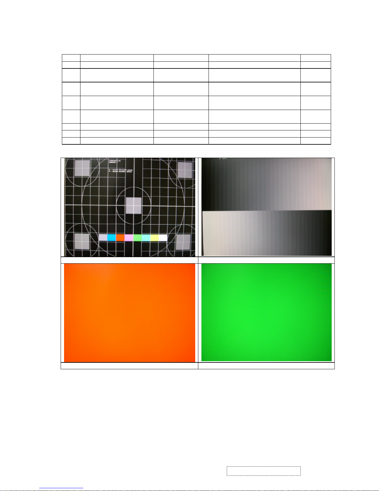
Test pattern
Item
Test condition Pattern Specification Remark
1 Frequency & performance Cross-hatch pattern No noise is allow & all color is clear Pattern 1
2 Monitor saturation 16-gray scale pattern 3~4 level need to saturated when
brightness & contrast is 100%
Pattern 2
3 RGB color performance RGB color Check the color temperature of
RGB signal color
Pattern 3,
4 Sub-pixel defect RGB color Check the sub-pixel defect Pattern 3,
4 , 5
5 Full white Full white Check the brightness ,CR & bright
pixel defect
Pattern 6
6 Full black Full black Pattern 7
7. 5-cycle pattern 5-cycle pattern Check the BU Pattern 8
8. 1-dot pattern 1-dot pattern Check the flicker Pattern 9
Pattern 1 Pattern 2
Pattern 3 Pattern 4
33
ViewSonic Corporation Confidential
-
Do Not Copy VX710
Page 37
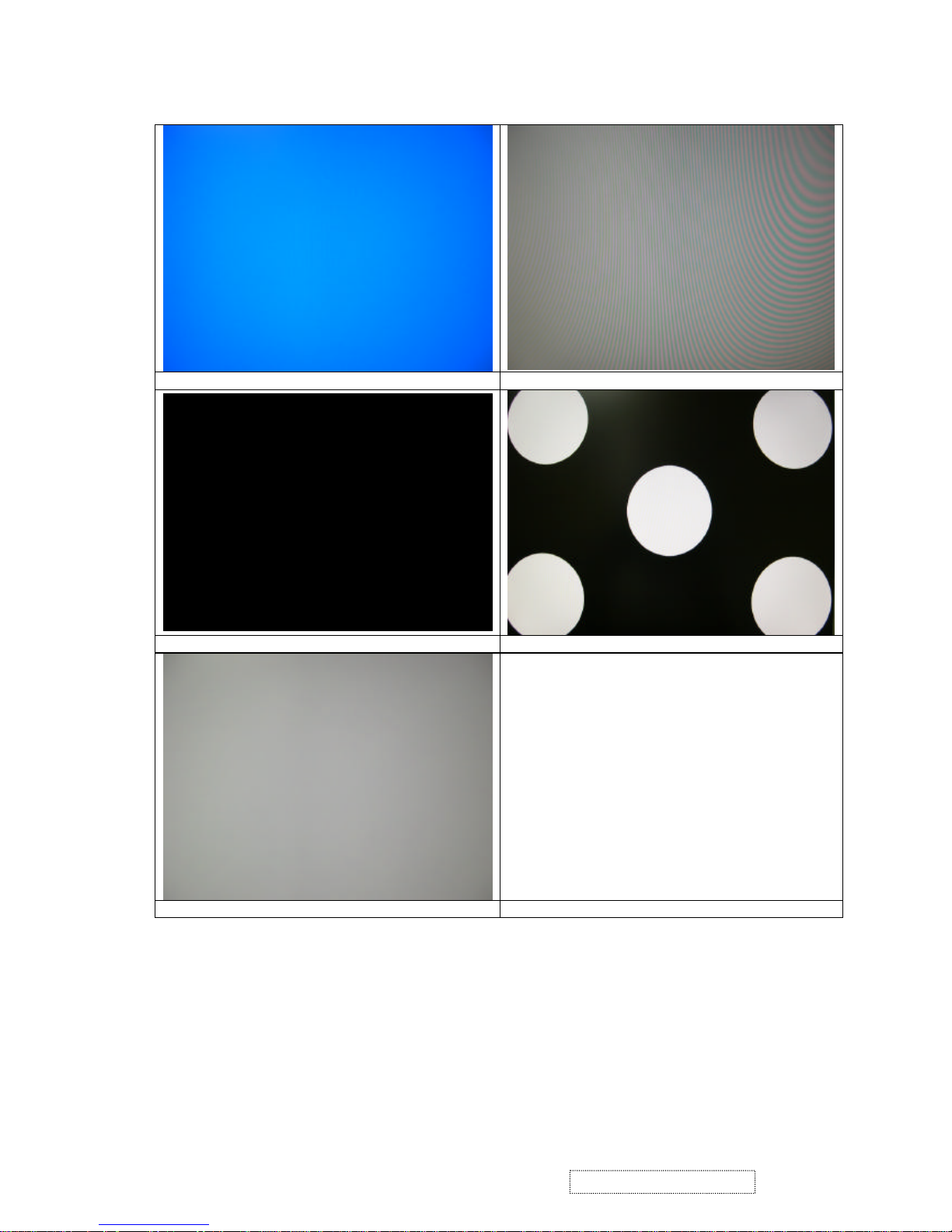
Pattern 5 Pattern 6
Pattern 7 Pattern 8
Pattern 9
34
ViewSonic Corporation Confidential
-
Do Not Copy VX710
Page 38
Firmware update procedure :
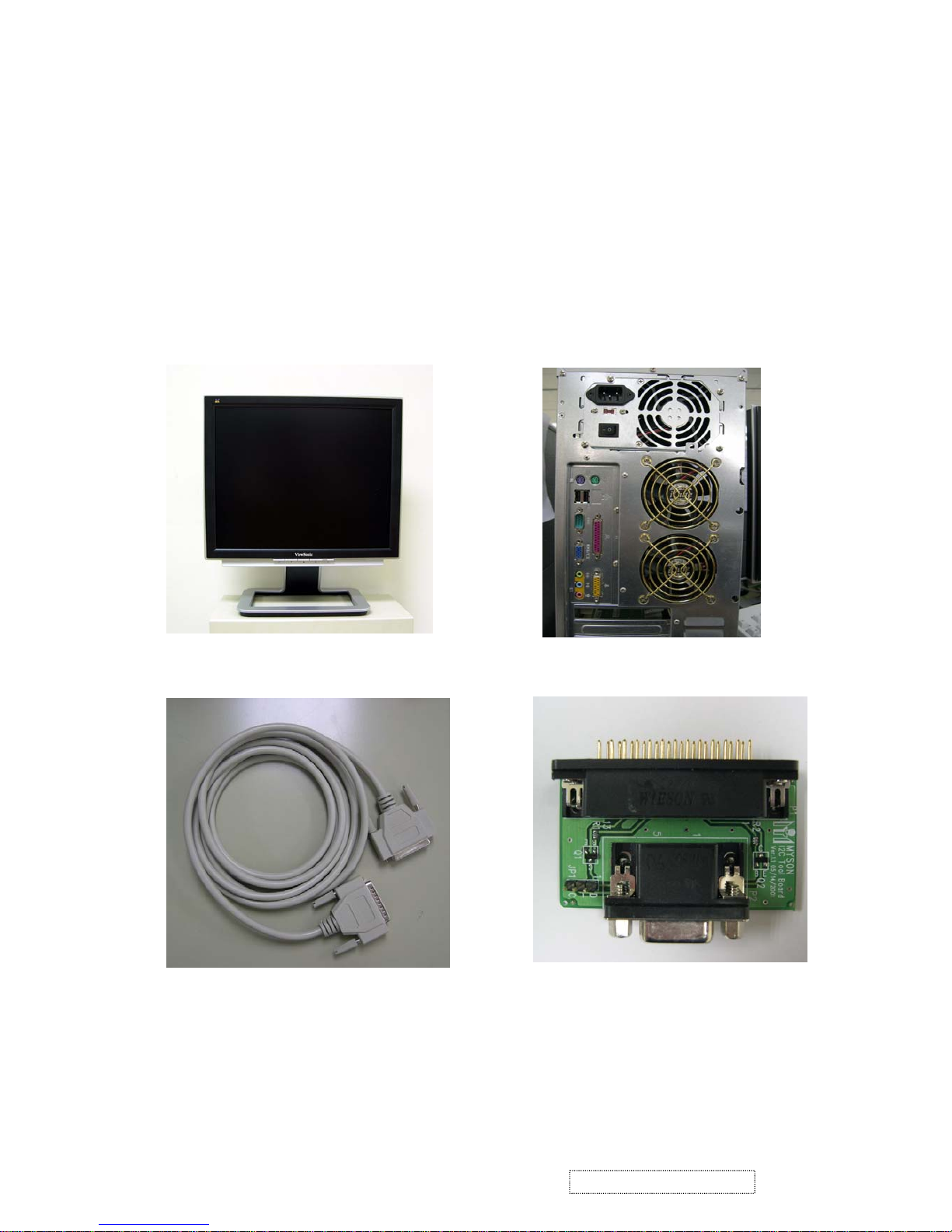
When you received a received monitor , please check whether the firmware version. If not , please
1. Equipment needed :
- VX710
- PC ( Personal computer )
- LPT cable
- Fixture (LM5ISP)
- Firmware upgrade program
following procedure to upgrade to the latest version .
35
ViewSonic Corporation Confidential
-
Do Not Copy VX710
Page 39
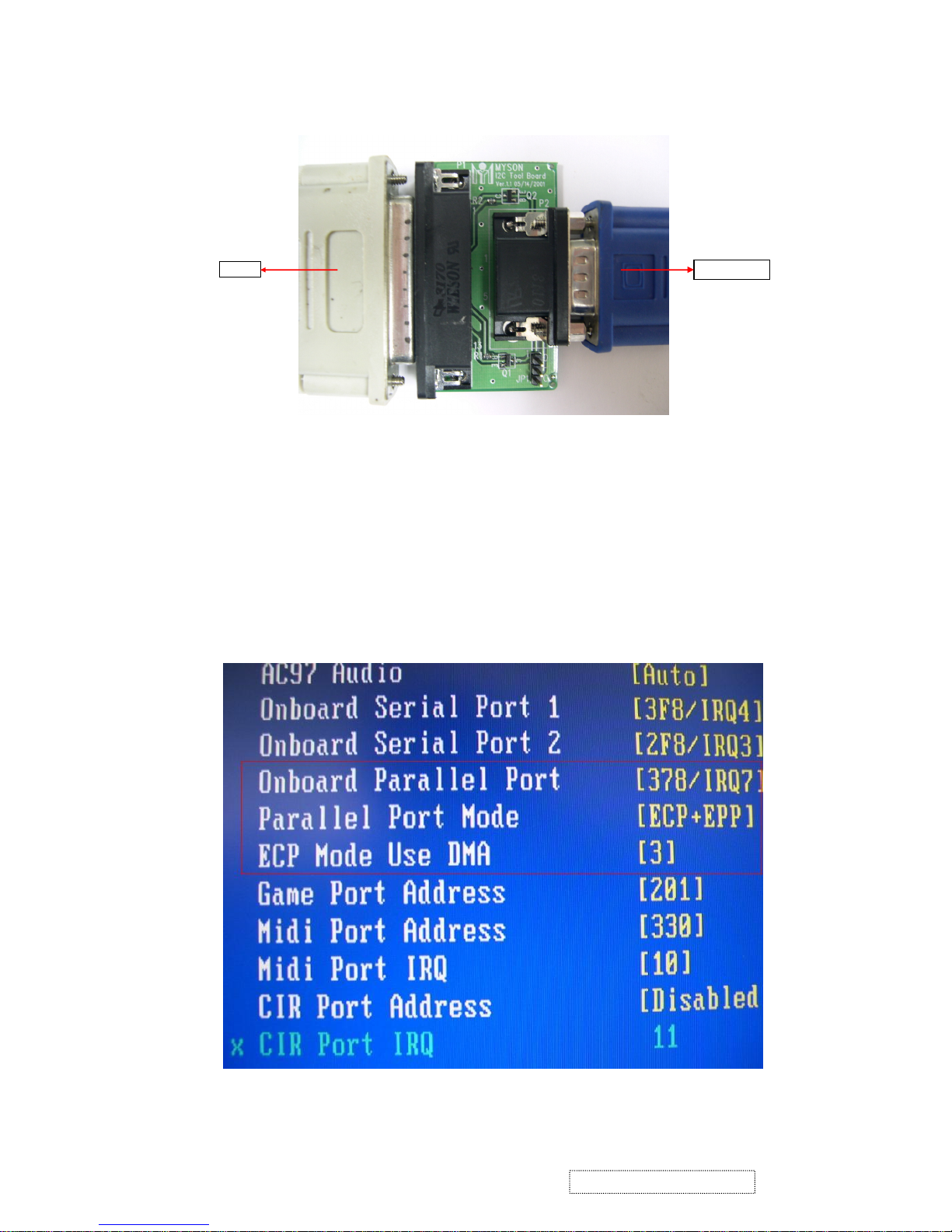
2. Connection :
To PC
To Monitor
Fig 0.0
Appendix A : How to install the software for ISP:
1. To set up ISP environment:
Hardware:
PC or notebook, parallel
(printer) cable, ISP tooling.
Software:
If OS is Win2000 or WinXP, please install "PORT95NT.exe".
In order to ensure that the system can execute the ISP program, please adjust the BIOS settings
in the PC or notebook as shown in Fig 0.0.
36
ViewSonic Corporation Confidential
-
Do Not Copy VX710
Page 40
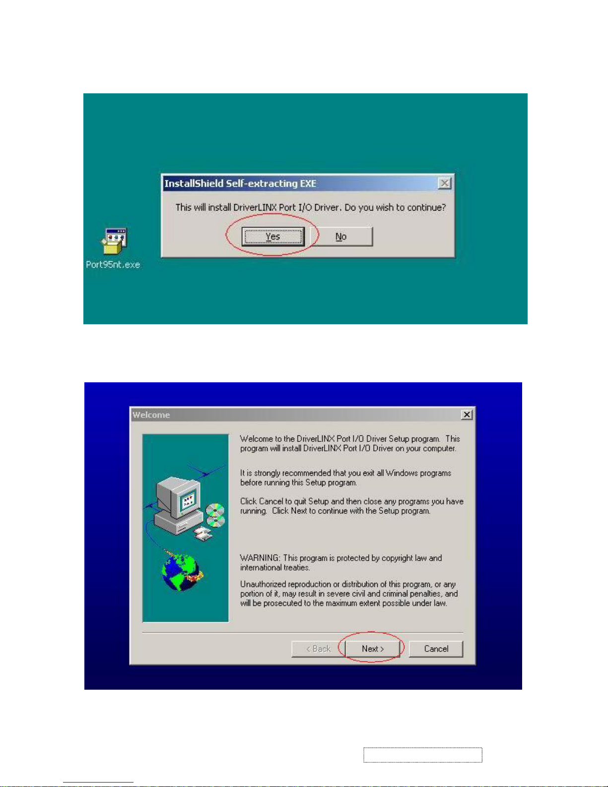
Fig 0.1
Fig. 0.2
2. Double-click the "PORT95NT.exe" icon in Windows and install the program; see Fig 0.1.
3. Continue through the installation process by pressing "Next" four times; see Fig. 0.2.
37
ViewSonic Corporation Confidential
-
Do Not Copy VX710
Page 41
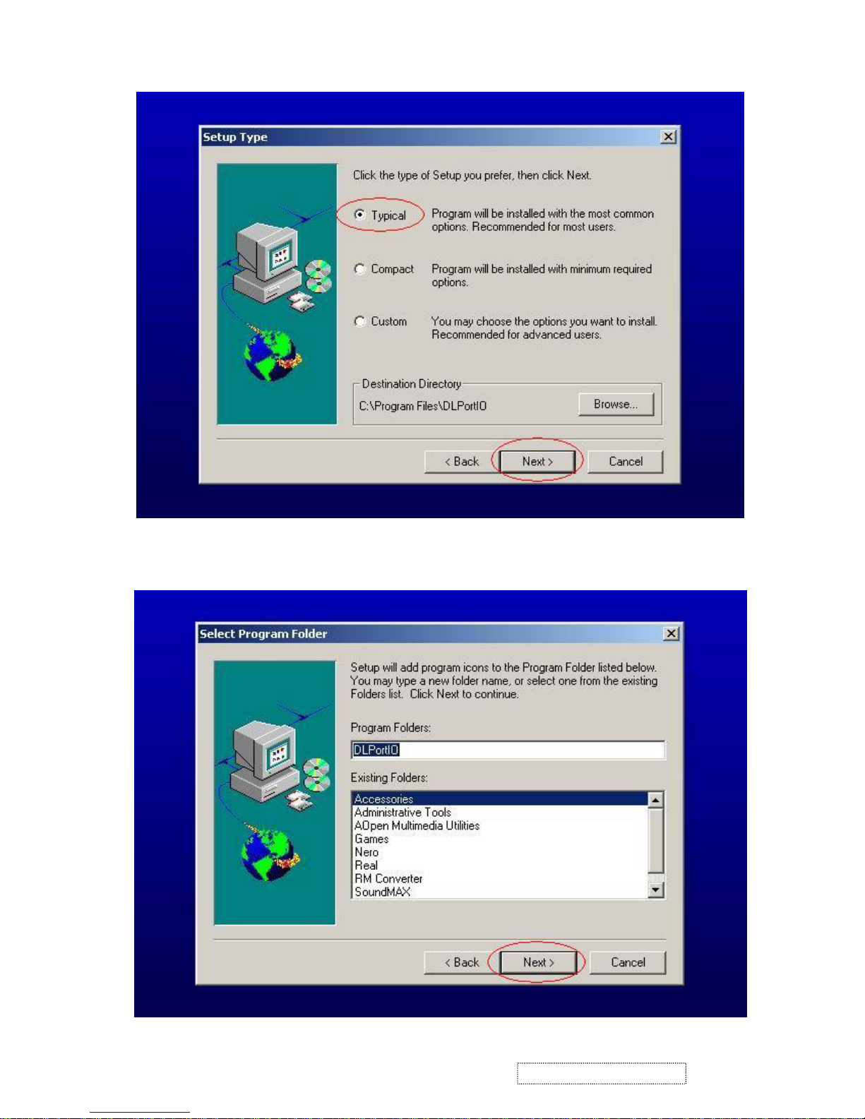
Fig. 0.3
Fig. 0.4
4. Choose "Typical" then press "Next;" see Fig. 0.3.
5. Continue through the installation process by pressing "Next" four times; see Fig. 0.4.
38
ViewSonic Corporation Confidential
-
Do Not Copy VX710
Page 42
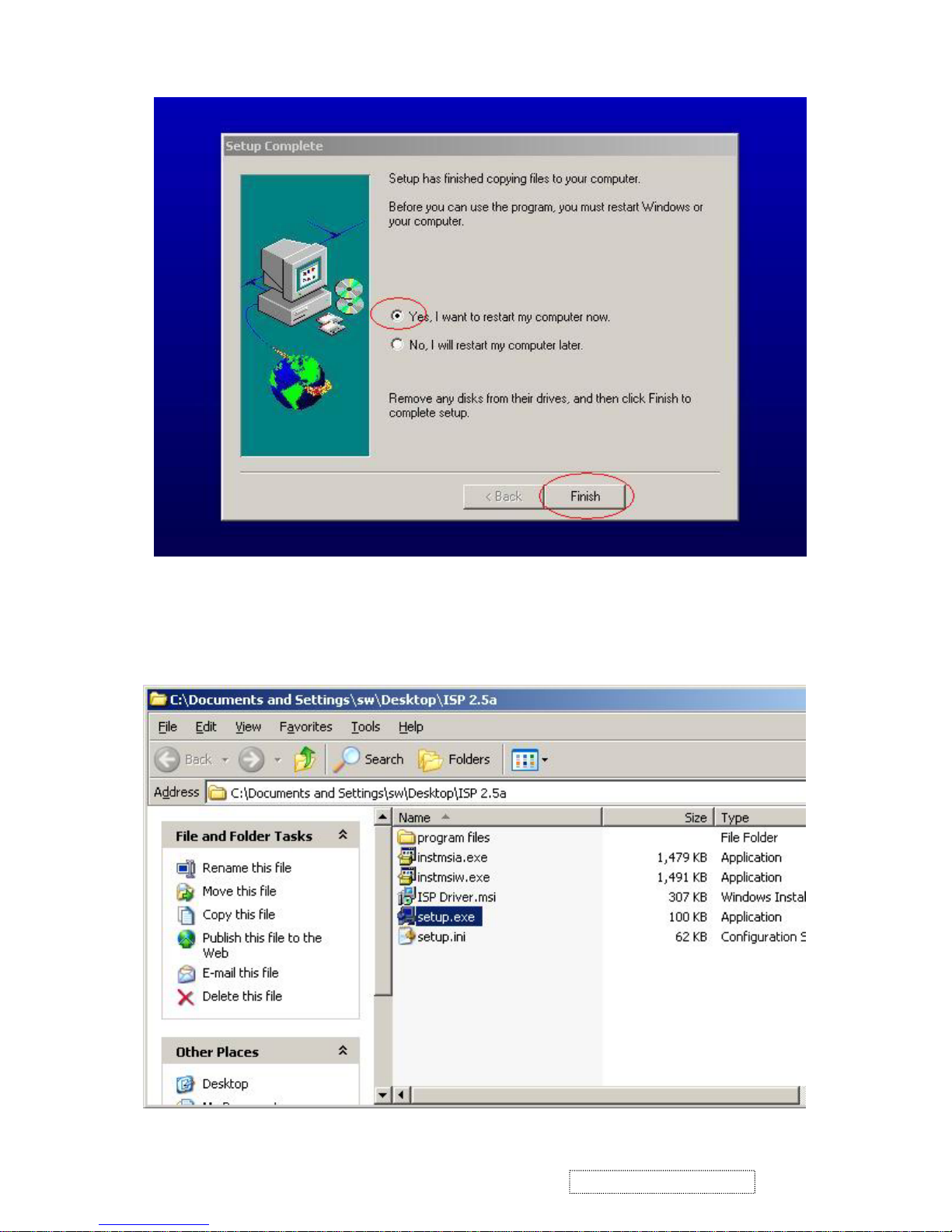
Fig. 0.5
Fig 1.0
6. When the installation is complete, restart the PC or notebook; see Fig 0.5.
Install ISP
1. The user may download the ISP driver and PORT95NT installation package from the Myson Century website
(www.myson.com.)
2. The files extracted from the ZIP file are listed in Fig 1.0. Double-click setup.exe to install.
39
ViewSonic Corporation Confidential
-
Do Not Copy VX710
Page 43
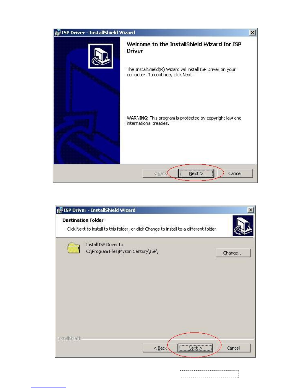
Fig 1.1
Fig 1.2
3. Press the "Next" button to continue; see Fig 1.1.
4. Press the "Change" button to change the install path if desired, and then press the "Next" button to
continue; see Fig 1.2.
40
ViewSonic Corporation Confidential
-
Do Not Copy VX710
Page 44
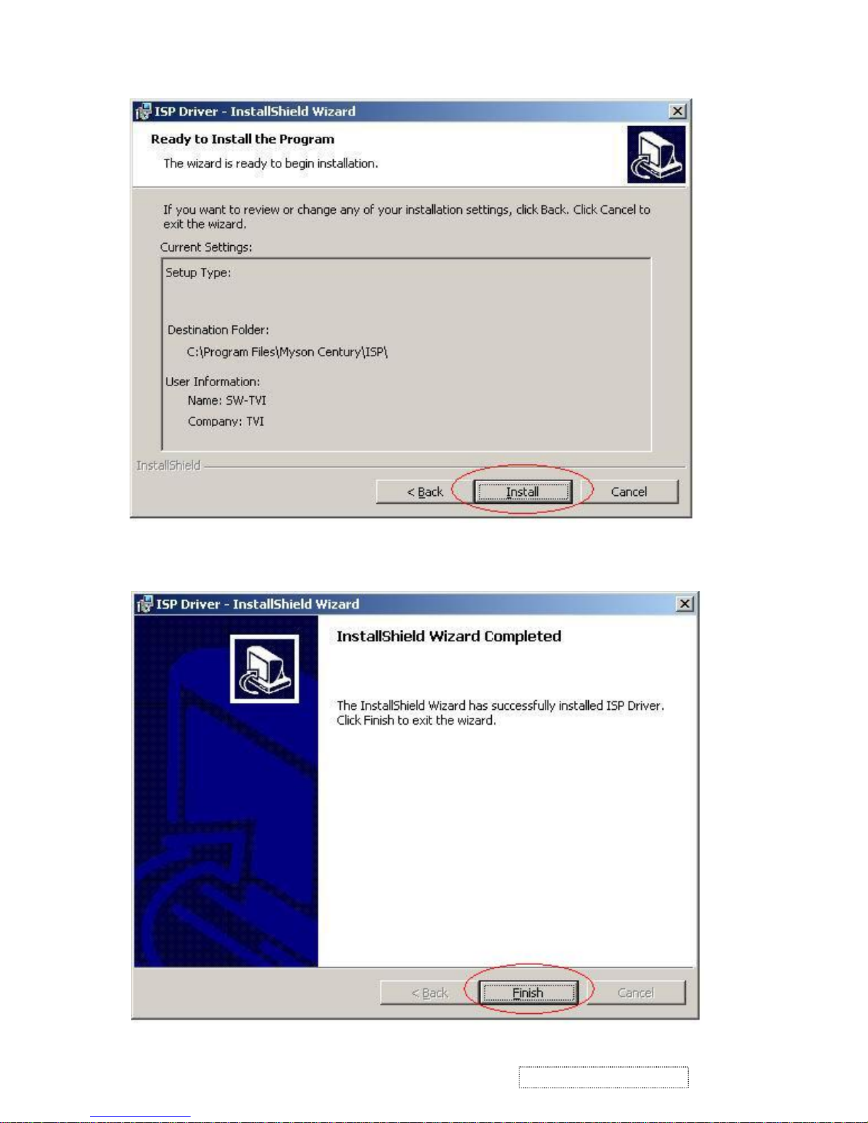
Fig. 1.3
Fig. 1.4
5. Press the "Install" button to continue; see Fig 1.3.
6. When installation has finished, press the "Finish" button; see Fig 1.4.
41
ViewSonic Corporation Confidential
-
Do Not Copy VX710
Page 45
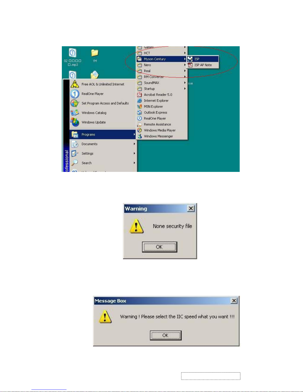
Fig. 2.1
Fig. 2.2
Fig. 2.3
Appendix B: How to use software to upgrade the BIOS:
1. After installation, shortcuts may be found in the settings path or the program menu (default setting); see Fig 2.1.
2. The security file is a key to use ISP functions; press the "OK" button. See Fig 2.2.
3. The warning shown in Fig. 2.3 is used to remind the user that a CPU rate that differs from IIC protocol
may cause the ISP functions to fail; press the "OK" button.
42
ViewSonic Corporation Confidential
-
Do Not Copy VX710
Page 46
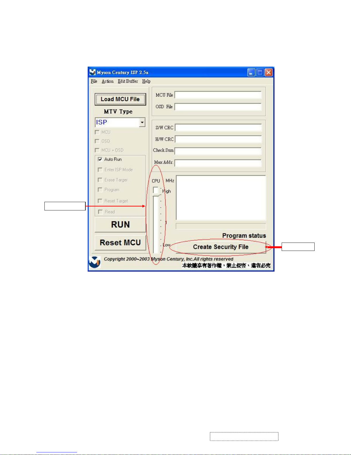
Fig. 2.4
Speed of IIC bus
Security code
4. As shown in Fig. 2.4, press the "Create Security File" button to key in a security code, and use the slider bar to
adjust the speed of the IIC bus.
43
ViewSonic Corporation Confidential
-
Do Not Copy VX710
Page 47
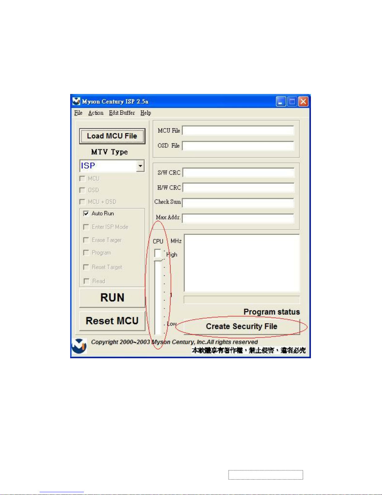
Fig. 2.5
5. Fig 2.5 shows the settings for the ISP software's security code. It requires two command numbers,
and the commands must be keyed in sequentially: 7C, 4C, 77. The command numbers and commands
must be set by the user while coding. For more details, please refer to section 6 boot code of ISP.
44
ViewSonic Corporation Confidential
-
Do Not Copy VX710
Page 48
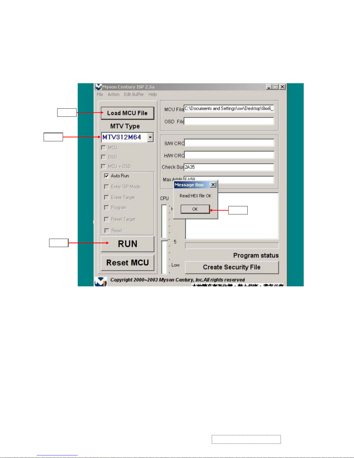
Fig. 3.1
Step 3
Step 1
Step 2
Step 4
Appendix C: Using ISP to program MCU
1. As shown in Fig. 3.1, select the MTV type first, load the binary or intel hex file to be programmed into the
MCU, click "OK," then press the "RUN" button.
45
ViewSonic Corporation Confidential
-
Do Not Copy VX710
Page 49
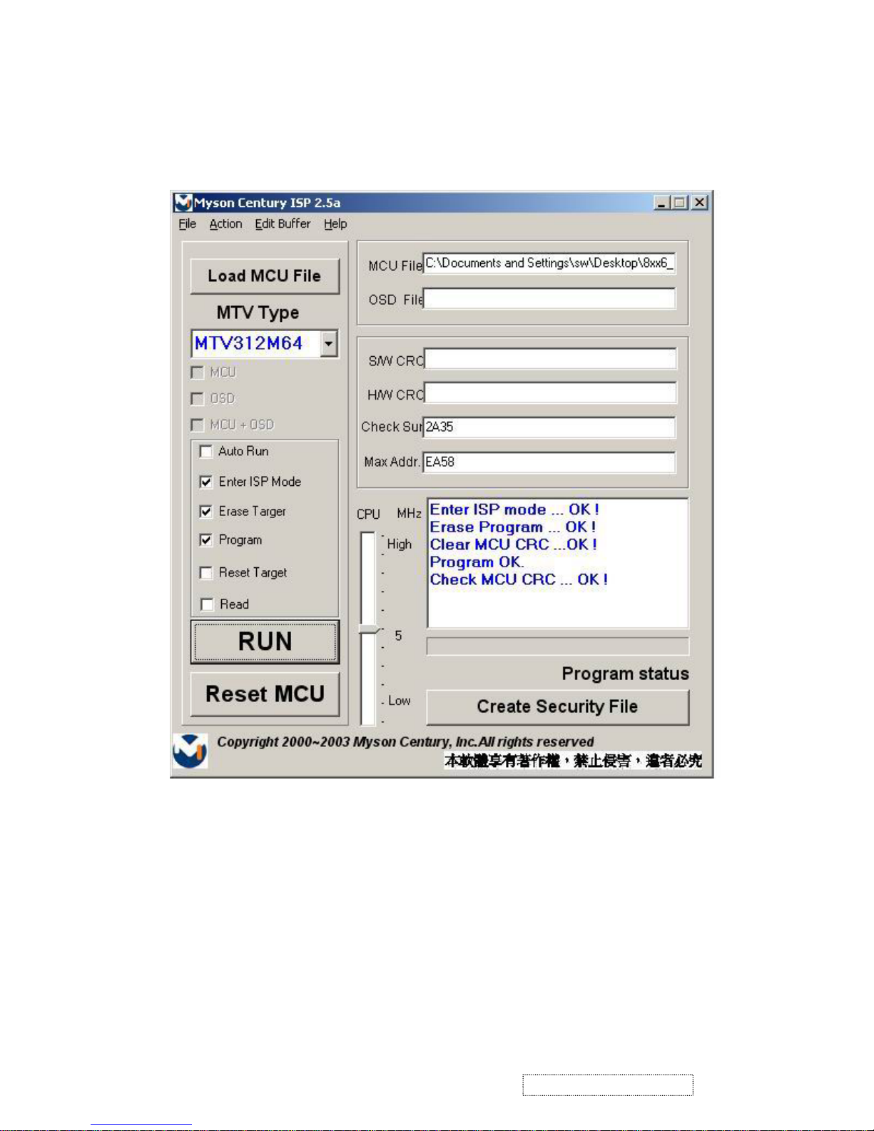
Fig. 3.2
2. If the user changes the MTV type, the file must be loaded again, as the previously loaded file will be cleared.
3. CRC (cyclic redundancy check): the host can check the result in the CRC register instead of reading every byte in flash.
The Check MCU CRC OK message indicates that the host has verified the program's CRC; see Fig.3.2.
46
ViewSonic Corporation Confidential
-
Do Not Copy VX710
Page 50
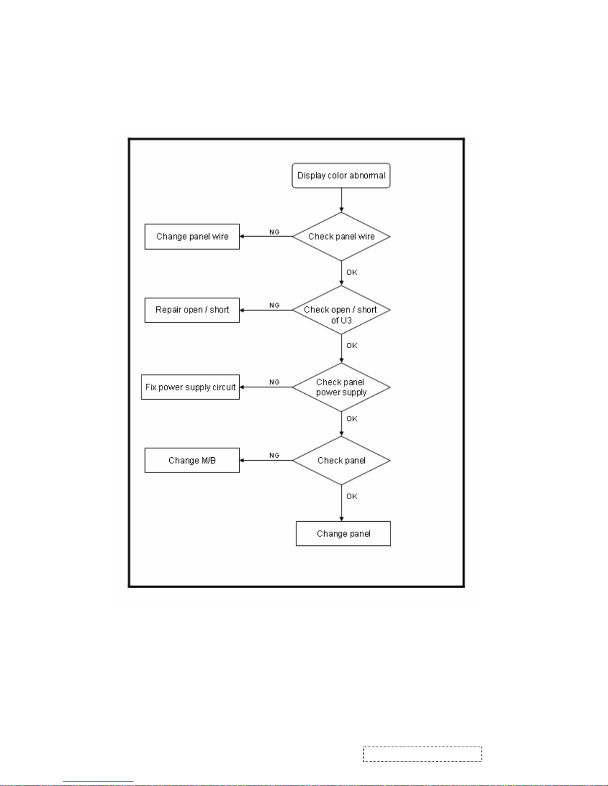
1. Display color abnormal:
6. Troubleshooting Flow Chart
47
ViewSonic Corporation Confidential
-
Do Not Copy VX710
Page 51
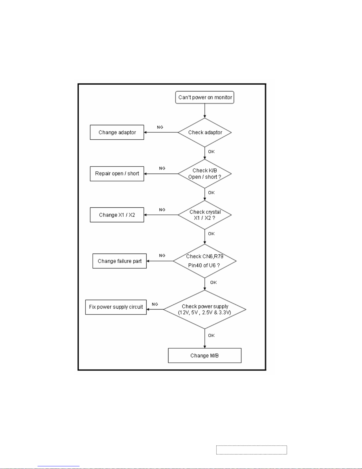
2.. Monitor can not power on
48
ViewSonic Corporation Confidential
-
Do Not Copy VX710
Page 52
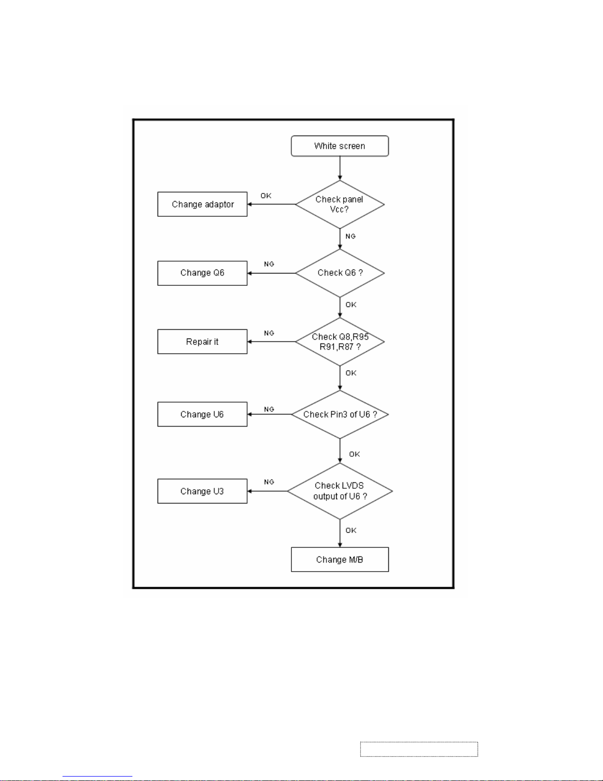
3. Monitor white screen
49
ViewSonic Corporation Confidential
-
Do Not Copy VX710
Page 53
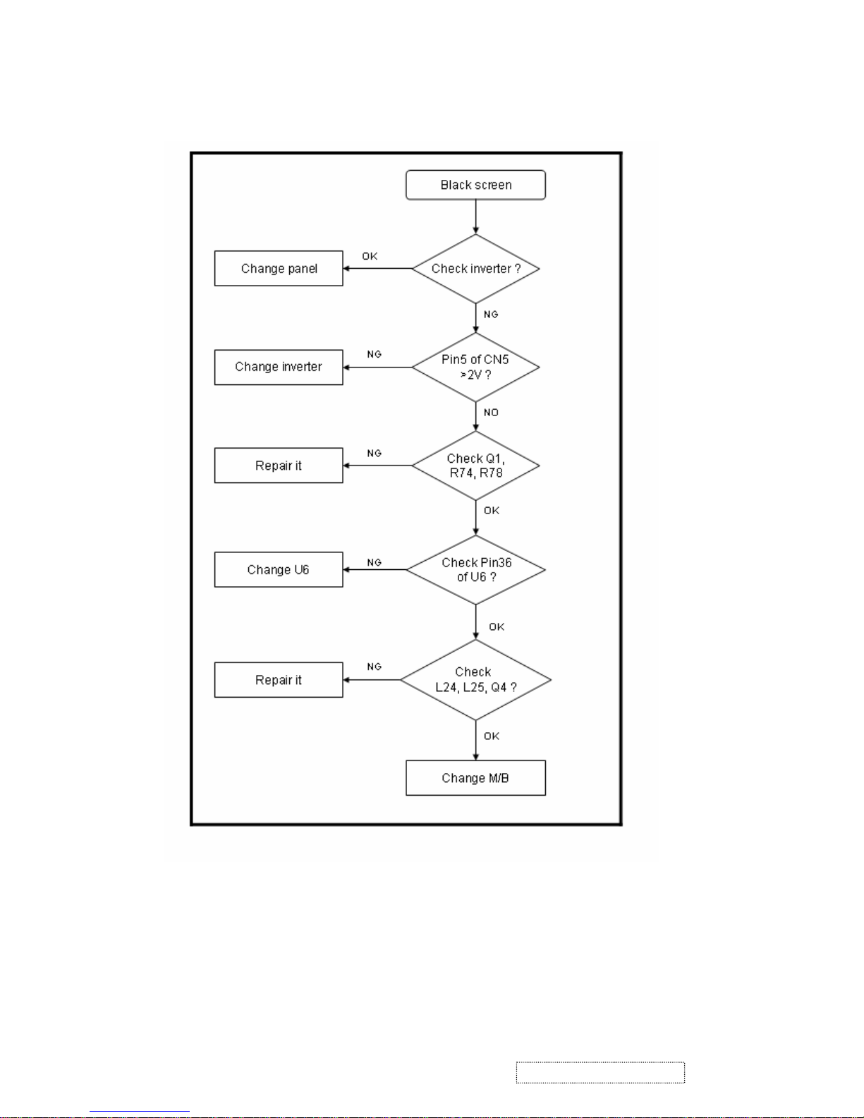
4. Monitor black screen
50
ViewSonic Corporation Confidential
-
Do Not Copy VX710
Page 54
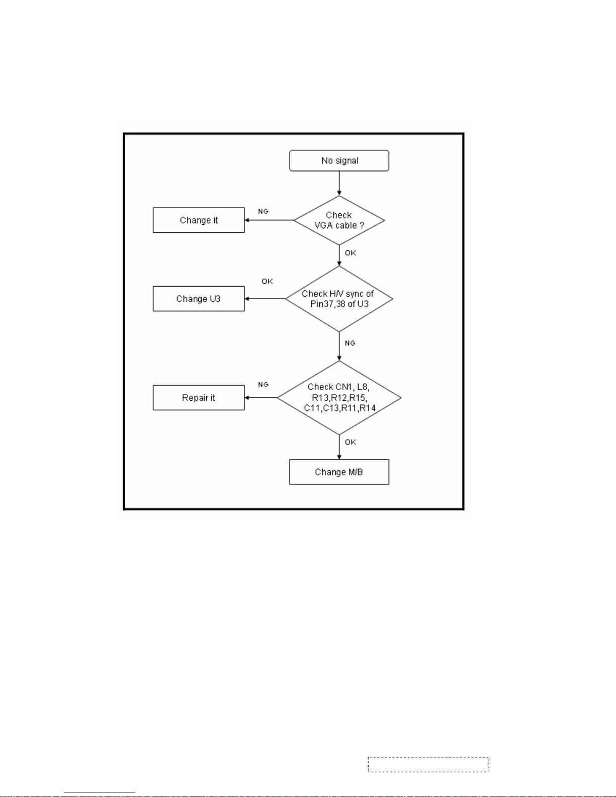
5. Analog input: always shows NO SIGNAL:
51
ViewSonic Corporation Confidential
-
Do Not Copy VX710
Page 55
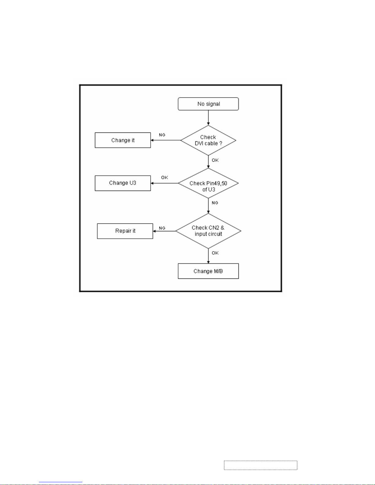
6. Digital input: always shows NO SIGNAL
52
ViewSonic Corporation Confidential
-
Do Not Copy VX710
Page 56
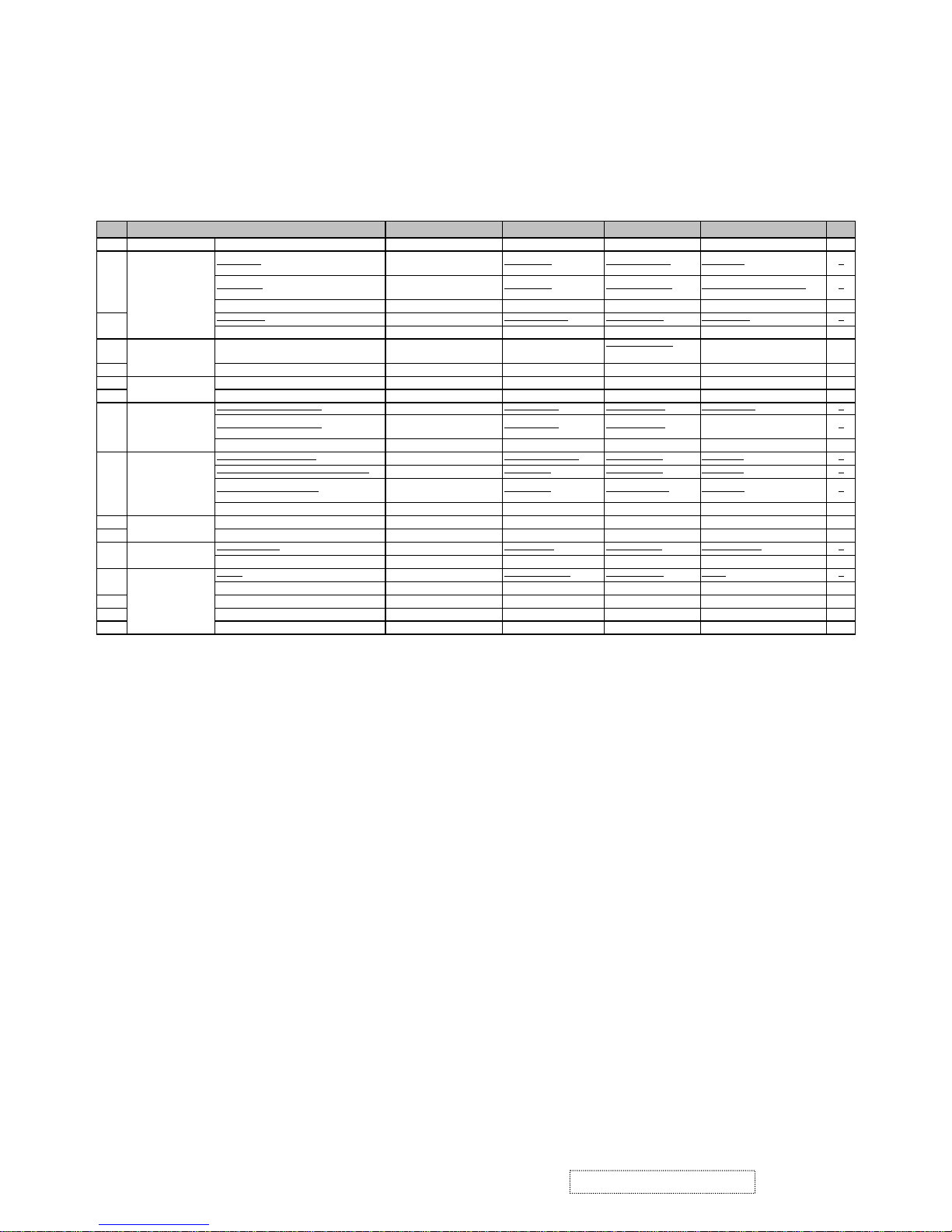
Rev: 1d
Item ECR/ECN ViewSonic P/N Ref. P/N Location Q'ty
1
Accessories:
VGA cable M-MS-0808-9399 DDL7VDPC005 VGA cable 1
Main board
V005(4745)
Removed 12/17/04
B-00000429
10MBZZZVSH0 main board 1
Main Board
Added 12/17/04
Removed 04/25/05
B-00000976
10MBZZZVSM9 M/B ASSY(RTD2523)AU 1
Main board Added 04/25/05 ECO 5288 B-00002461 29L9IMB00D7 M/B ASSY(RTD2523)QDI 1
Power board
Removed 12/17/04 B-PS-0204-0076 AS02B012D24 power board 1
Power board Added 04/25/05 B-00002481 AS02B012DA6 ADD/INV,FSP035-1PI01 1
4 Back cover assy
Correct vendor p/n
12/17/04
C-00000430
37L7VBBCVS54
37L7VBCVS54
back cover 1
5 Front bezel assy C-FP-0301-9935 33L7VFBVS53 front bezel ass'y 1
6 Cable for MB-BB (8P, Rev1A) M-MS-0808-9398 DDL7VDTH009 MB-BB cable 1
7 Cable for MB-LCD (30P. Rev.1A) M-FC-0809-0845 DDL70LLC308 MB-LCD cable 1
User's manual + CD wizard
Removed 12/17/04 A-CD-VX710 HGL7V008012 User's manual 1
User's manual + CD wizard
Added 12/17/04
Removed 04/25/05
DC-00000977
HGL7V009019 1
User's manual + CD wizard Added 04/25/05 ECO 5288 DC-00002462 HGL7V014012 User's manual 1
17" LGL TFT LCD panel
Removed 12/17/04 M-LCD-0824-0181 AA170E01001 LCD panel 1
17" LGL TFT LCD panel (2nd source) Removed 12/17/04 E-00000431 AA170E01010 LCD panel 1
17" AUO TFT LCD panel
Added 12/17/04
Removed 04/25/05
E-00000978
AAM170EG015 LCD Panel 1
17" QDI TFT LCD panel Added 04/25/05 ECO 5218 E-00002216 AA17EL07055 LCD panel 1
10 Screw M3.0*5.0-I(NI) M-SCW-0824-0728 MM30050IBJ3 screw 23
11 Screw HW-00000432 MM30070BBJ1 screw 9
LCD film L7VD
Removed 12/17/04 M-00000433 JXL7V004013 LCD panel film 1
LCD film L7VD Added 12/17/04 M-MS-0808-7399 JXL7V003017 LCD panel film 1
Carton
Removed 12/17/04 P-BX-0601-0971 HFL7V010016 carton 1
Carton Added 12/17/04 P-00000979 HFL7V012019 carton 1
15 End cap (L) P-FM-0602-0875 HBL7V007011 cushion 1
16 End cap (R) P-FM-0602-0876 HBL7V008018 cushion 1
17 EPE bags P-00000434 HAL7V005018 EPE bags 1
Board Assembly:
3
2
8
Documentation:
13
14
Miscellaneous:
9
Electronic
Components:
Description
ViewSonic Model Number: VS10049
RECOMMENDED SPARE PARTS LIST (VX710-1)
Cabinets:
Packing Material:
Cables:
Hardware:
7. Recommended Spare Parts List
53
ViewSonic Corporation Confidential
-
Do Not Copy VX710
Page 57
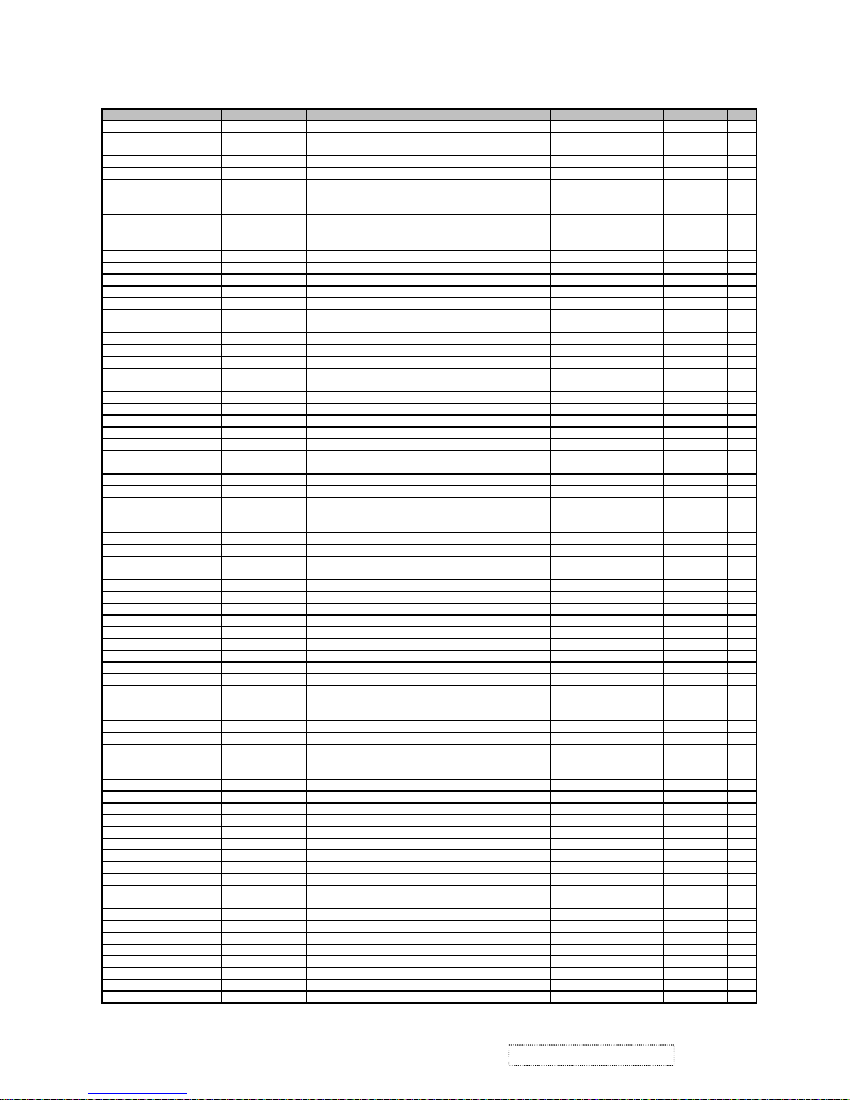
ViewSonic Model Number: VS10049
Rev: 1d
Item
ViewSonic P/N
Ref. P/N
Description
Location
Universal No.
Qty
1
#N/A
1L7VDZQVS02
L7VD-Q LCD MONITOR(QDI)US
2
B-00002461
29L9IMB00D7
L9I M/B ASSY(FOR L7VD-Q,REALTEK 2523)QDI
13#N/A
L9I204-01
39L9IDP0005 MB Schematic(B3A)TSU16AK
04#N/A
39L9IDP0005
L9I M/B DIP ASSY(FOR L7VD REALTEK)
15#N/A
41L9ISS0002
L9I M/B S/S ASSY(FOR L7VD REALTEK)
1
6 #N/A CC62204MD23 CAP ELEC 22U 25V(+-20%,105C,5*11,2000HR)
C34,C46,C50,C53,C59,C84,
EC1,EC2,EC3,EC5,EC6
11
7 #N/A CC622L4MD06 CAP ELEC DIP 22U 25V(+-20%,105C,5*11)LXN
C34,C46,C50,C53,C59,C84,
EC1,EC2,EC3,EC5,EC6
11
8
#N/A
CC71004MD68
CAP ELEC 100U 25V +-20%,105C,6*11,LESR
C7019
#N/A
CC710L4MD08
CAP ELEC 100U 25V(+-20%,105C,6*11)LXN
C70110
#N/A
CC73303MD51
CAP ELEC 330U 16V(+-20%,105C,8*11,2000HR
C6,EC4
211E-L-0407-1563
DC04725K002
CHOKE COIL 47UH(2.5A,+-10%,T07473)
L2112
#N/A
BG624576031
CRYSTAL DIP 24.576MHZ(30PPM,20PF,49/US)
Y1113
#N/A
BG611059319
CRYSTAL DIP 11.0592MHZ(+-30PPM,49/US)
Y2114
#N/A
DFHD06MR247
CONN DIP HEADER 6P 2R MR(P2.5,H6.0)
CN1115
#N/A
DFDS15FR050
CONN D-SUB 15P 3R FR,P1.15,H12.55,NO SRW
CN2116
#N/A
DFDI30FR049
CONN DVI-I DIP30P 3R FR(P1.905,H10.04)
CN4117
M-MS-0808-9809
DFHD30MR259
CONN DIP HEADER 30P 2R MR(P2.0,H4.0)
CN5118
M-MS-0808-9810
DFHD10MR316
CONN DIP HEADER 10P 1R MR(P2.0,H4.1)
CN6119
#N/A
AZL7VD0Q008
L7VD SW BIOS IMAGE REALTEK CHIP(QDI)
120B-00002481
AS02B012DA6
ADD/INV,FSP035-1PI01H ,90~264V REV1A
121B-CB-0206-0188
23L7VBB0034
L7VD BUTTON/B ASSY
122#N/A
DFHD08MR301
CONN DIP HEADER 8P 1R MR(P2.0,H4.1)
CN1123
#N/A
BEYG0013DA3
LED(DIP) YELLOW/GREEN(L-3WYGW)
LED1124
#N/A
DAL7VDTB1A3
PCB(BUTTON) L7VD TL(1L,180*15,REVA)
1
25 #N/A DHP0002B205 SWITCH PUCH BUTTON(PT-002-B2,50MA,12V) SW1,SW2,SW3,SW4,SW5 5
26
#N/A
22L7VLAVSF7
L7VD-Q LCD MODULE ASSY(QDI)
127C-FP-0301-9935
33L7VFBVS53
L7VD FRONT BEZEL ASSY
128#N/A
33L7VFB5
L7VD FRONT BEZEL ASSY
029C-FP-0301-0992
EAL7V019019
BEZEL L7VD(EAL7V019,REV3A)
130C-FP-0301-0994
EAL7V020017
MIDDLE BEZEL L7VD(EAL7V020,REV3A)
131M-MS-0808-9401
EBL7V028019
LENS L7VD(EBL7V028,REV3A)
132PL-BT-0706-0165
EBL7V027012
CONTROL BUTTON L7VD(EBL7V027,REV3A)
133M-MS-0808-9243
FEL7V003019
LOGO FRONT-VSC-38MM L7VC(FEL7V003,REV3A)
134M-MS-0808-9402
FEL7V007014
BIRD LOGO L7VD(FEL7V007,REV3A)
135C-BC-0302-0598
37L7VBCVS54
L7VD BACK COVER ASSY
136#N/A
37L7VBC5
L7VD BACK COVER ASSY
037M-CV-0830-2543
EAL7V021013
LCD COVER L7VD(EAL7V021,REV3A)
138M-MS-0808-9253
FEL7V005011
LOGO PLATE ELLIPSE L7VC(FEL7V005,REV3A)
139M-MS-0808-9411
FBL70008014
LOCK METAL L70B(FBL70008,REV3A)
140M-CV-0830-2542
FBL7V042011
HINGE -L L7VD(FBL7V042,REV3B)
141M-CV-0830-2544
FBL7V043018
HNGE-BKT L7VD(FBL7V043,REV3A)
142M-CV-0830-2545
FBL7V044014
HINGE-R L7VD(FBL7V044,REV3B)
143M-SCW-0824-6822
MF30070BBJ1
SCREW F3.0*7.0-B (NI)
444M-SCW-0824-6760
MS30060IM18
SCREW F3*6-I(NI)
445M-MS-0808-9406
MM40080FL69
SCREW M4.0*8.0-F (BNI,NYLOK)
446E-00002216
AA17EL07055
LCD(TFT) 17" QD17EL07 REV:09
147M-BK-0805-0079
FAL7V014017
PCB BKT L7VD(FAL7V014,REV3A)
148M-MS-0808-9405
FAL7V015013
PCB SHIELDING L7VD(FAL7V015,REV3A)
149M-BK-0805-0077
FBL7V038014
LCD BKT-L L7VD(FBL7V038,REV3A)
150M-BK-0805-0078
FBL7V039011
LCD BKT-R L7VD(FBL7V039,REV3A)
151M-SCW-0824-0728
MM30050IBJ3
SCREW M3.0*5.0-I(NI)
2352M-SCW-0824-0870
MS40070B808
SCREW M4*7B (BMC)NYLOK
453M-SCW-0824-6825
MM30040IJ21
SCREW M3.0*4.0-I(BNI)
454M-SCW-0824-6761
MM30030IBJ4
SCREW M3*3-I-NI
455M-MS-0808-9247
EBL70023013
WIRE MOUNTS L70L-E(EBL70023,REV3A)
156#N/A
GAL7V013011
RUBBER PLUG VESA L7VD (GAL7V013,REV3A)
457M-MS-0808-8986
MBLI1004018
IO NUT LI1(MBLI1004,REV3A)
458M-SCW-0824-6799
MM35080BBW2
SCREW M3.5*8-B (NI,WASHER)
159C-BS-0303-0536
26L7VSAVS33
L7VD STAND ASSY
160#N/A
26L7VSA3
L7VD STAND ASSY
061#N/A
34L7VSSVS13
L7VD STAND SUB ASSY
162M-BK-0805-0081
FBL7V040019
STAND BKT L7VD(FBL7V040,REV3B)
163M-MS-0808-9403
FBL7V041015
STAND PLATE L7VD(FBL7V041,REV3A)
164#N/A
GAL7V011018
RUBBER FOOT L7VD(GAL7V011,REV3A)
565M-SCW-0824-6824
MM40060FL60
SCREW M4.0*6.0-F (BNI,NYLOK)
466M-CV-0830-2547
EAL7V023016
STAND BASE L7VD(EAL7V023,REV3A)
167M-SCW-0824-0728
MM30050IBJ3
SCREW M3.0*5.0-I(NI)
268M-CV-0830-2546
EBL7V024013
STAND COVER F L7VD(EBL7V024,REV3A)
169M-SCW-0824-6760
MS30060IM18
SCREW F3*6-I(NI)
270M-SCW-0824-6822
MF30070BBJ1
SCREW F3.0*7.0-B (NI)
9
BOM LIST (VX710-1)
54
ViewSonic Corporation Confidential
-
Do Not Copy VX710
Page 58
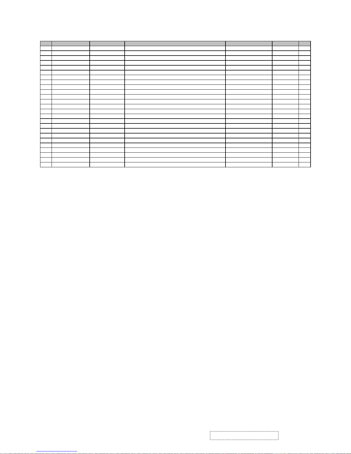
Item
ViewSonic P/N
Ref. P/N
Description
Location
Universal No.
Qty
71
M-MS-0808-9404
EBL7V029015
WIRE CLAMP L7VD(EBL7V029,REV3A)
272#N/A
23L7VCSVS79
L7VD CHASSIS ASSY(LG)
173M-MS-0808-9398
DDL7VDTH009
CABLE ASSY L7VD BUTTON-MB(8P/10P,REV1A)
174M-FC-0809-0845
DDL70LLC308
CABLE ASSY L70L_EB MB-LCD(30P80MM,REV2A)
175M-SCW-0824-0813
MF30060BBJ6
SCREW F3.0*6-B(NI)
276#N/A
EBL7V030013
PCB SPACER L7VD(EBL7V030,REV3A)
177#N/A
24L7VPKVSV1
L7VD-Q PACKING ASSY(US)
178M-MS-0808-9399
DDL7VDPC005
CABLE ASSY L7VD MB-VGA (15/15P,REV1A)
179A-PC-0106-0224
DM333181G97
POWER CORD 3P 1.8M(USA)V04VS35001218000
180M-CV-0830-2540
EBL7V026016
I/O COVER L7VD(EBL7V026,REV3A)
181M-CV-0830-2541
EBL7V025010
STAND COVER R L7VD(EBL7V025,REV3A)
182P-00000434
HAL7V005018
EPE BAG L7VD(HAL7V005,REV3A)
183P-FM-0602-0875
HBL7V007011
END CAP(L) L7VD(HBL7V007,REV3A)
184P-FM-0602-0876
HBL7V008018
END CAP(R) L7VD(HBL7V008,REV3A)
185M-LB-0813-0747
HCL7V004013
CORE LABEL(HCL7V004,REV3A)
186#N/A
HCL7V021015
ID LABEL L7VD(HCL7V021,REV3B)
187M-LB-0813-0745
HCL7V002011
SERIAL LEBAL L7V(HCL7V002,REV3A)
188M-LB-0813-1042
HCL7V019011
CARTON LABEL L7VC(HCL7V019,REV3B)
189P-00000979
HFL7V012019
CARTON VX710 L7VD(HFL7V012,REV3A)
190DC-00002462
HGL7V014012
CD+QSG L7VD-Q USA(HGL7V014,REV3A)
191#N/A
JXLM5003011
HANDLE LM5S(JXLM5003,REV 3B)
192M-MS-0808-7399
JXL7V003017
LCD FILM L7VC(JXL7V003,REV3B)
193M-LB-0813-1043
HCL70021011
HI-POT LABEL L70L(HCL70021,REV3A)
194#N/A
HFL7V011012
SPACE PLATE L7VD(HFL7V011,REV3A)
0.0595M-00002264
HCL7V028010
8MS STICKER L7VC(HCL7V028,REV3A)
1
55
ViewSonic Corporation Confidential
-
Do Not Copy VX710
Page 59
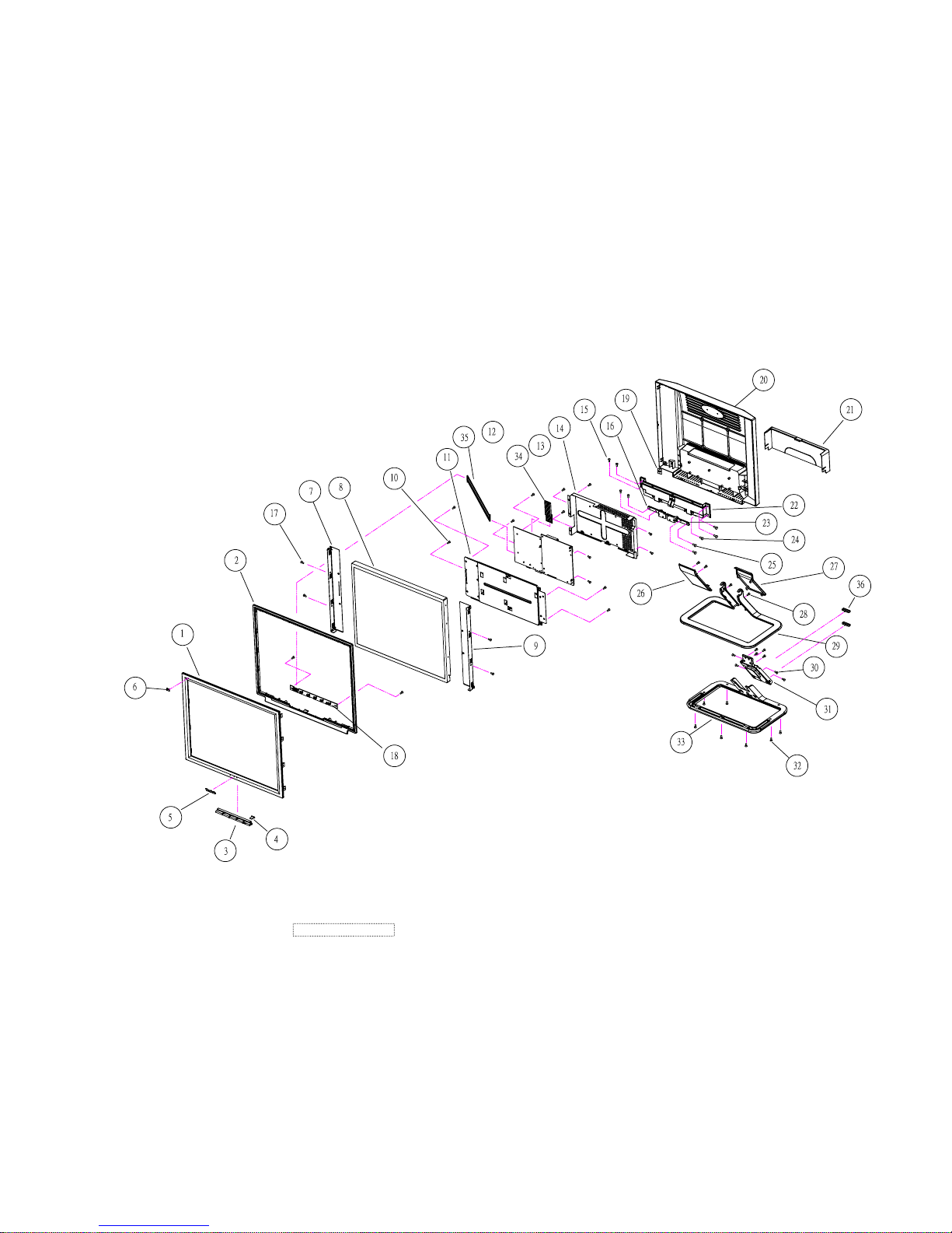
8. Exploded Diagram And Spare Parts List
56
ViewSonic Corporation Confidential - Do Not Copy VX710
Page 60
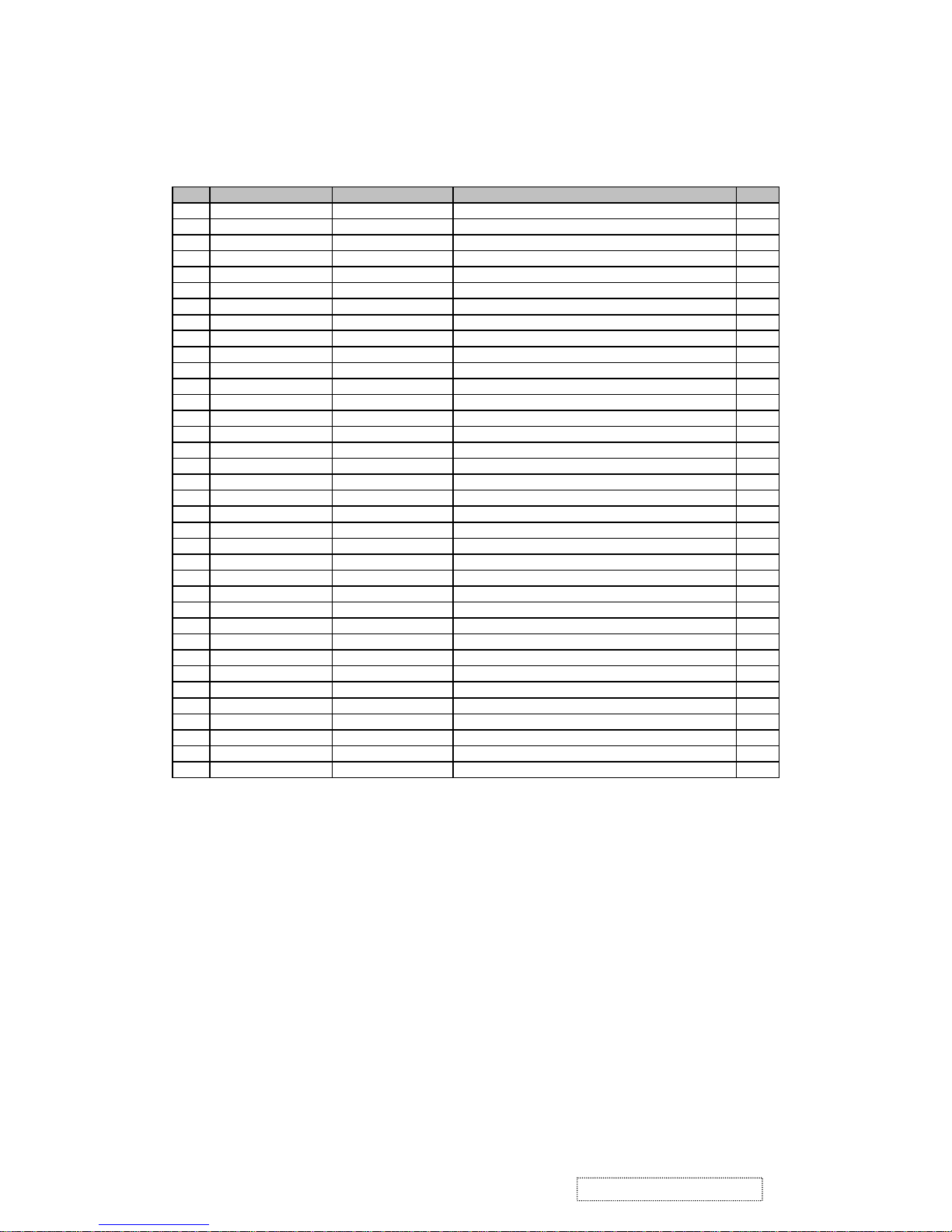
Rev: 1d
Item ViewSonic P/N Ref. P/N Description Qty
1 C-FP-0301-0992 EAL7V019019 Bezel 1
2 C-FP-0301-0994 EAL7V020017 Middle bezel 1
3 PL-BT-0706-0165 EBL7V027012 CONTROL BUTTON L7VD(EBL7V027,REV3A) 1
4 M-MS-0808-9401 EBL7V028019 LENS 1
5 M-MS-0808-9243 FEL7V003019 Logo front -VSC 1
6 M-MS-0808-9402 FEL7V007014 BIRD LOGO L7VD(FEL7V007,REV3A) 1
7 M-BK-0805-0077 FBL7V038014 LCD-BKT-L 1
8 E-00002216 AA17EL07055 LCD(TFT)17" QD17EL07 V.9 SVGA 1
9 M-BK-0805-0078 FBL7V039011 LCD-BKT-R 1
10 M-SCW-0824-0728 MM30050IBJ3 SCREW M3.0*5.0-I(NI) 10
11 M-BK-0805-0079 FAL7V014017 PCB-BKT 1
12 B-00002481 AS02B012DA6 ADD/INV,FSP035-1PI01,90~264V REV1A 1
13 B-00002461 29L9IMB00D7 M/B ASSY(FOR L7VD REALTEK,RTD2523)QDI 1
14 M-MS-0808-9405 FAL7V015013 PCB SHIELDING L7VD(FAL7V015,REV3A) 1
15 M-SCW-0824-6822 MF30070BBJ1 SCREW F3.0*7.0-B (NI) 4
16 M-CV-0830-2542 FBL7V042011 Hinge-L 1
17 M-SCW-0824-6825 MM30040IJ21 Screw M3*4-I 4
18 B-CB-0206-0188 23L7VBB0034 PCB-Button 1
19 M-MS-0808-9411 FBL70008014 Lock Metal 1
20 M-CV-0830-2543 EAL7V021013 LCD cover 1
21 M-CV-0830-2540 EBL7V026016 I/O cover 1
22 M-CV-0830-2544 FBL7V043018 Hinge BKT 1
23 M-CV-0830-2545 FBL7V044014 Hinge-R 1
24 M-SCW-0824-6760 MS30060IM18 SCREW F3.0*6-B(BNI) 4
25 M-MS-0808-9406 MM40080FL69 Screw M4*8-I 4
26 M-CV-0830-2546 EBL7V024013 Stand cover front 1
27 M-CV-0830-2541 EBL7V025010 Stand cover rear 1
28 M-SCW-0824-6760 MS30060IM18 SCREW F3.0*6-B(BNI) 2
29 M-CV-0830-2547 EAL7V023016 Stand base 1
30 M-SCW-0824-6824 MM40060FL60 Screw M4*6-F 4
31 M-MS-0808-9403 FBL7V041015 Stand plate 1
32 M-SCW-0824-6822 MF30070BBJ1 Screw F 3*7-B 9
33 M-BK-0805-0081 FBL7V040019 Satnd BKT 1
34 M-FC-0809-0845 DDL70LLC308 Cable ass'y L70L MB/LCD 1
35 M-MS-0808-9398 DDL7VDTH009 Cable Ass'y button / MB 1
36 M-MS-0808-9404 EBL7V029015 WIRE CLAMP 2
EXPLODED PARTS LIST (VX710-1)
ViewSonic Model Number: VS10049
57
ViewSonic Corporation Confidential
-
Do Not Copy VX710
Page 61
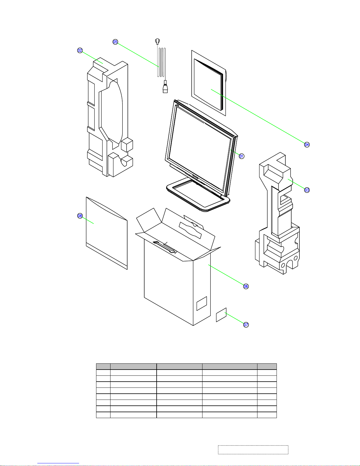
Packing for shipment
Rev: 1c
Item ViewSonic P/N Ref. P/N Description Qty
1 VX710 1L7VDZQVS02 VX710 unit 1
2 P-FM-0602-0875 HBL7V007011 END CAP(L) 1
3 P-FM-0602-0876 HBL7V008018 END CAP(R) 1
4 DC-00002462 HGL7V014012 User manual & CD 1
5 A-PC-0106-0224 DM333181G97 Power cord 3P 1.8M 1
6 P-00000979 HFL7V012019 Carton 1
7 M-LB-0813-1042 HCL7V019011 Carton label 1
8 P-00000434 HAL7V005018 EPE bag 1
PACKING PARTS LIST (VX710-1)
ViewSonic Model Number: VS10049
58
ViewSonic Corporation Confidential
-
Do Not Copy VX710
Page 62
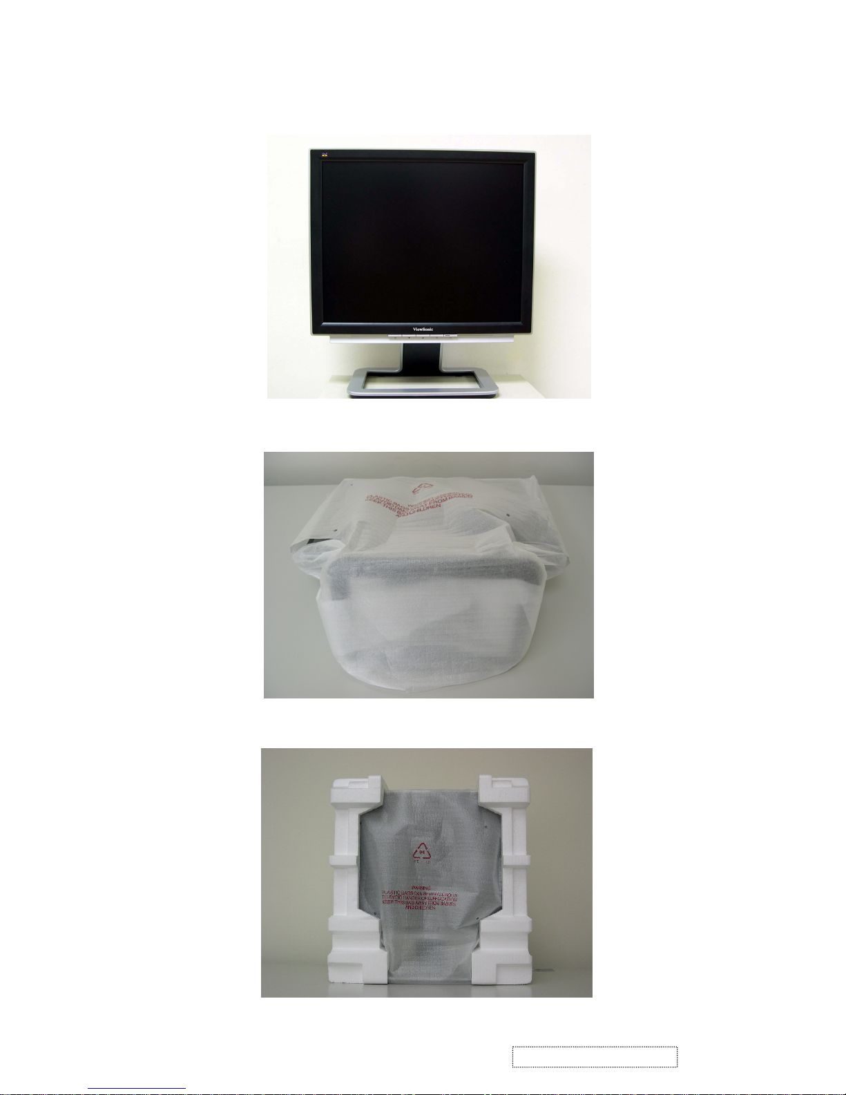
Packing procedure
1. Apply protective film to the display surface.
2. Put the monitor in EPE bag and seal the bag with tape.
3. Fit the cushions onto the monitor.
59
ViewSonic Corporation Confidential
-
Do Not Copy VX710
Page 63
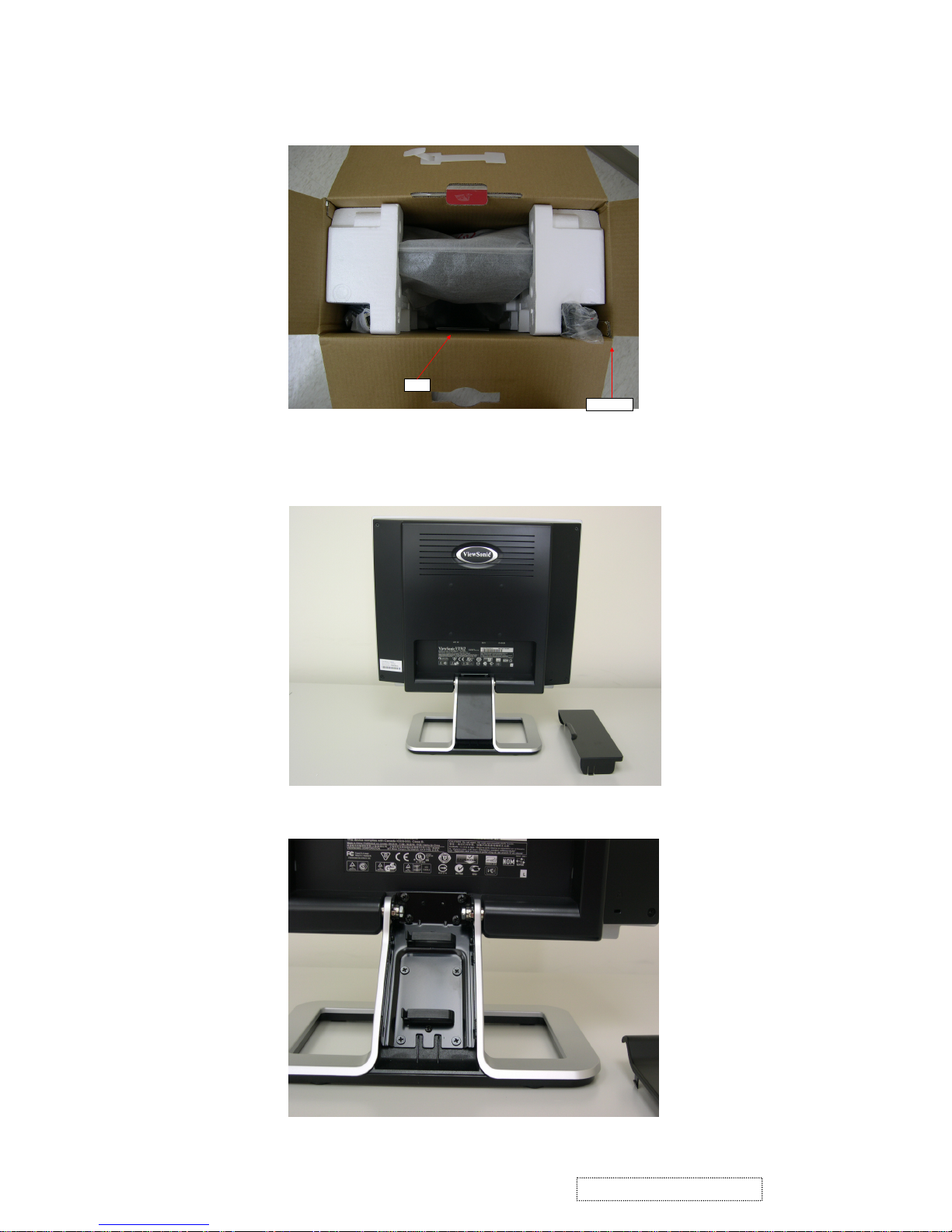
4. Put the monitor into the carton and put all the accessories into the carton.
Q
SG
Power cord
Then close the carton.
Disassembling the monitor
1. Turn the monitor to face the back and remove the I/O cover.
2. Remove the stand back cover.
60
ViewSonic Corporation Confidential
-
Do Not Copy VX710
Page 64
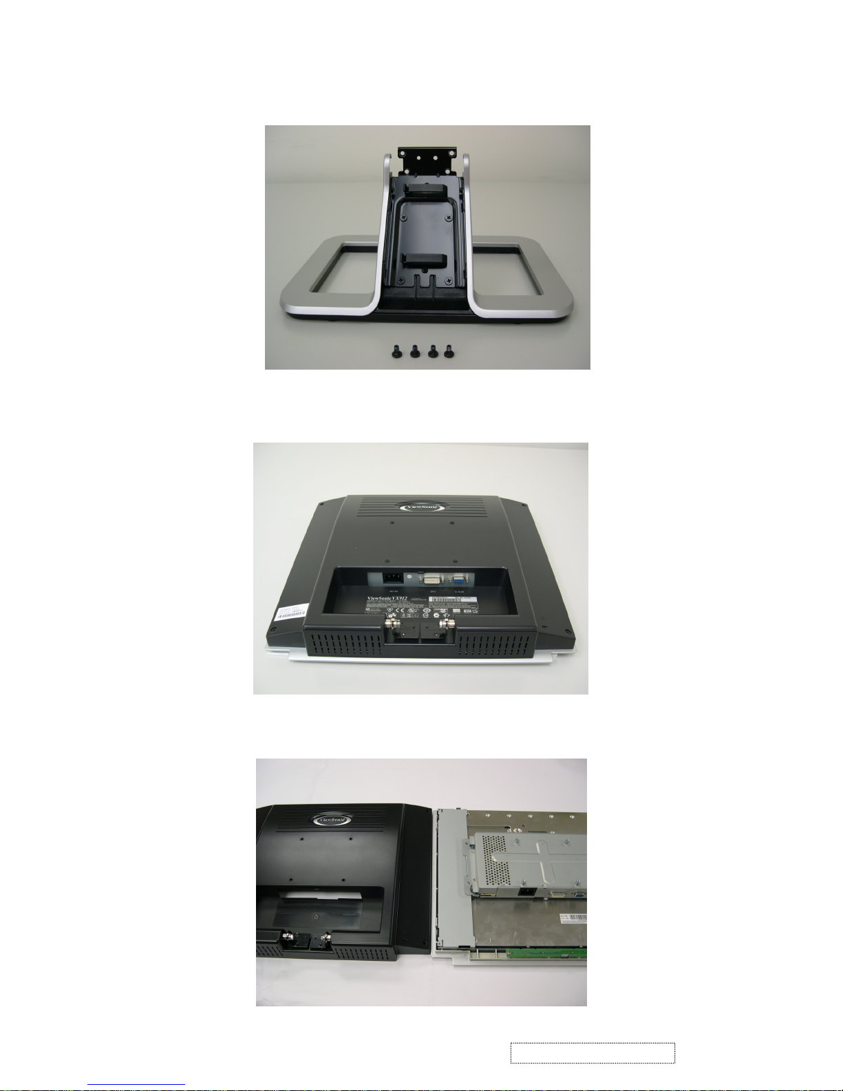
3. Remove the four black hinge screws and separate the stand and head pieces.
4. Place the monitor face-down on a soft, flat, stable surface.
5. Separate the back cover and the front bezel.
61
ViewSonic Corporation Confidential
-
Do Not Copy VX710
Page 65
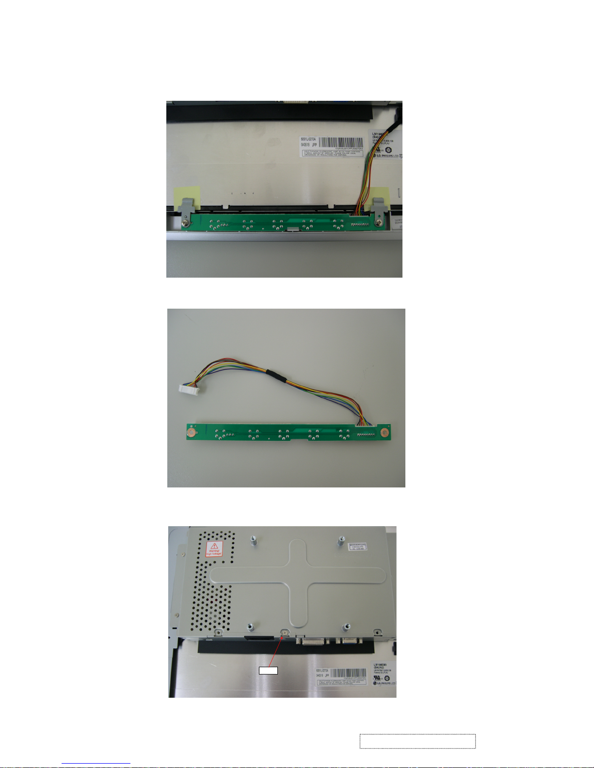
6. Remove the screws that fix the button board (B/B) and pull the cable out from the
7. Remove the B/B.
8. Remove the screws on the PCB shield; remove the PCB shield.
Screws
connector on the main board (M/B).
62
ViewSonic Corporation Confidential
-
Do Not Copy VX710
Page 66
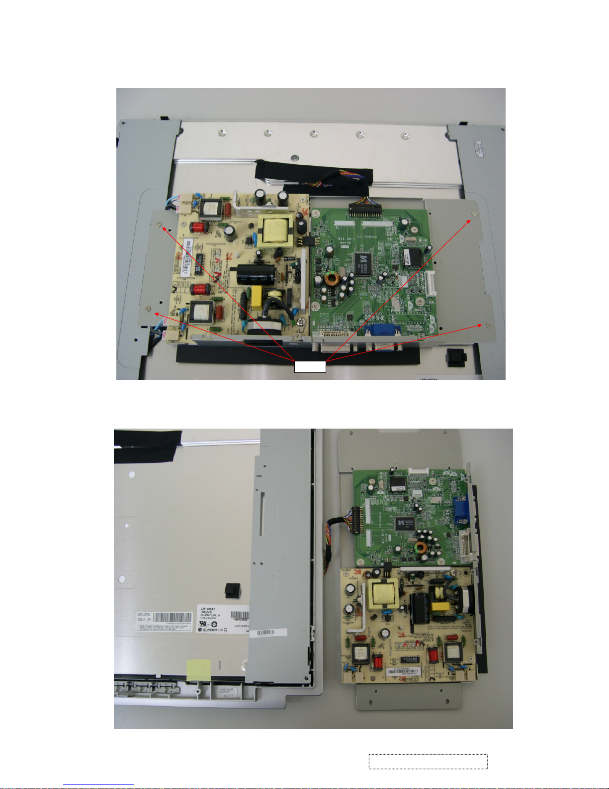
9. Remove the MB-LCD connector and loosen the four screws on the PCB holder.
Screws
10. Separate the PCB holder from the panel.
63
ViewSonic Corporation Confidential
-
Do Not Copy VX710
Page 67
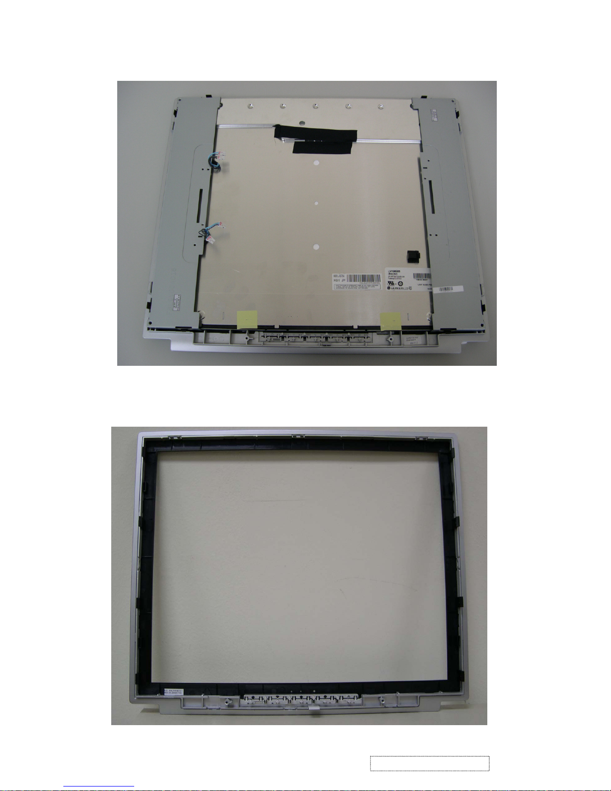
11. Loosen the four screws on the sides of the panel.
12. Remove the front bezel and panel.
64
ViewSonic Corporation Confidential
-
Do Not Copy VX710
Page 68
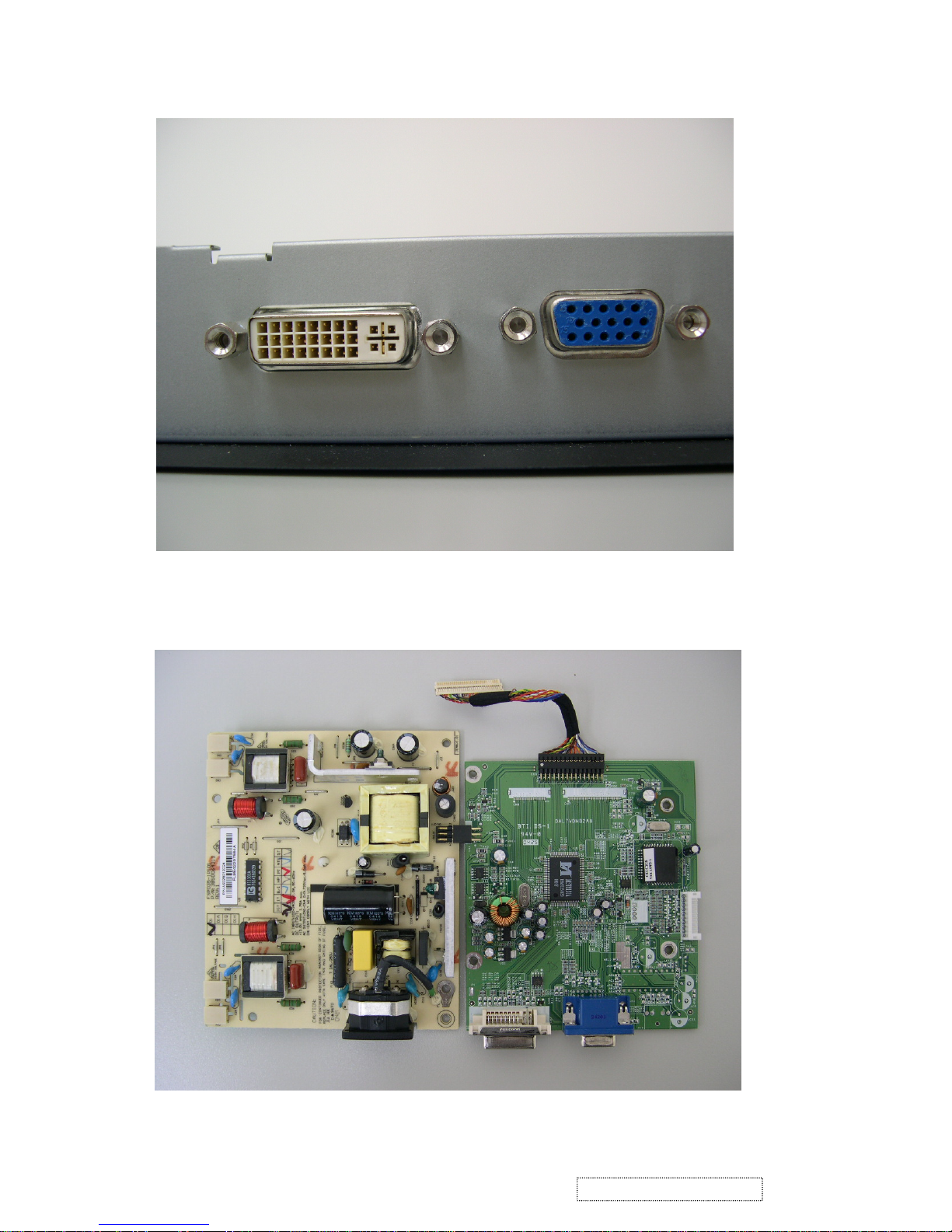
13. Remove the four hexagon screws beside the DVI & D-SUB connectors.
14. Remove the screws that fix the power board and main board.
65
ViewSonic Corporation Confidential
-
Do Not Copy VX710
Page 69
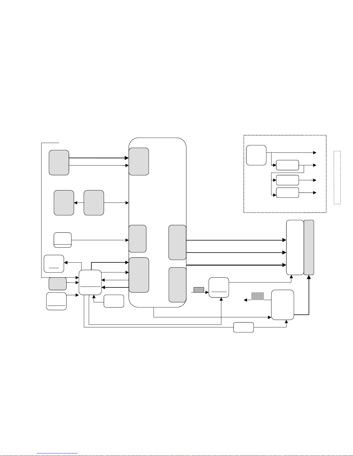
REALTEK RTD2523BLOCK DIAGRAM
DDC-SCL;DDC-SDA
AIC1563
AIC117ADJ
AIC1117ADJ
12V
5V
3.3V
2.5V
POWER
12V
ANALOG
RGB
17” Panel
Backlight
ADAPTOR
Backight
Control
Inverter
CPU
MTV312V64
RST
Keypad
SCL
SCL
SDA
SDA
BRIGHTNESS
5V
Switch
Si2301DS
RTD2523
Triple
ADC
Interface
Clock
GEN.
Host
Interface
Panel
Interface
EEPROM
24C16
Crystal
24.576MHz
IRQ
AR AG AB
HSYNC ,VSYNC
ON/OFF
CSZ
DDC
24C02
DVI
LVDS+
LVDS-
CLK+
CLK-
Panel
Inverter
control
ISP
12V
Crystal
11.059MHz
9. Block Diagram
66
ViewSonic Corporation Confidential
-
Do Not Copy VX710
Page 70
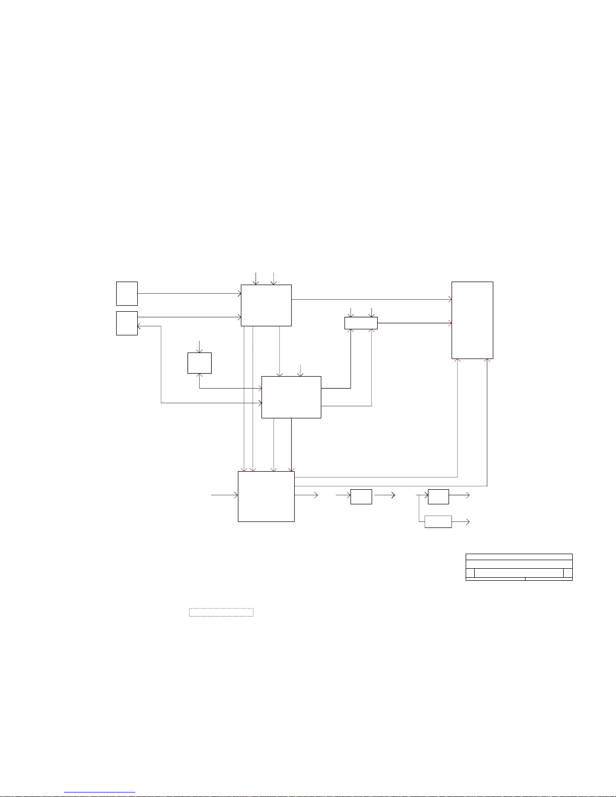
+3.3V
AUDIO_MUTE
+12V
AIC1739
RSDS AND LVDS
+2.5V
POWER
PC
VGA
LCDVCC
+3.3V
+3.3V
+2.5V
LCDPWR_ON12V
INVCTRL
+12V
EEPROM
24LC16
SCALAR RTD2523
LCD
PANEL(17
19 RSDS
AND
LVDS)
AC 90-264V
BRIGHTNESS
ANALOG RGB
LCDPWR_ON3.3V
DDC
MICRO-CONTROLLER
MTV312
+5.0V
DVI
AIC
1563
POWER INVERTER
AND AUDIO BOARD
+3.3V
AUDIO_VOLUME
+3.3V
AIC1739
+3.3V
BLOCK DIAGRAM
<Doc>
<Title>
C
Friday, October 15, 2004
Title
Size Document Number
Rev
Date:
67
ViewSonic Corporation
Confidential - Do Not Copy VX710
10. Schematic Diagrams
Page 71
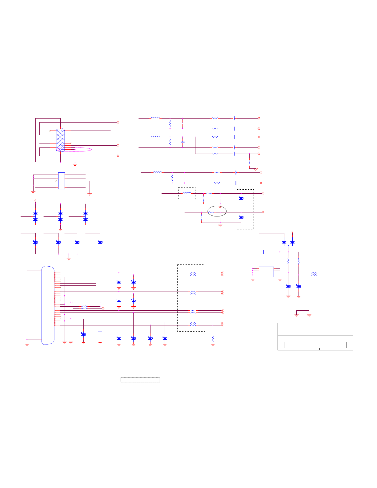
PAGE1 VGA
INPUT
Add R156~R162 damping RES 2004/4/16
PIN 10 VGA_CON
DEL L11,C32,U6,R51,R52 2004/6/17
Add D34,D35,L31
2004/6/17
DEL D29 2004/6/17
DISPLAY
VGA AND DVI INPUT
Friday, October 15, 2004
B
Title
Size Document Number
Rev
Date:
BLUE+IN
BLUE+IN
GREEN+IN
IN-V
IN-H
DDC2_SCL
BLUE+IN
BLUE+IN
IN-V
DSUB_5V
RED+IN
IN-H
RED+IN
DDC2_SDA
RED+IN
VGAVS
DDC_SCL
IN-V
GREEN+IN
RED+IN
Bus_Power
Bus_Power
IN-V
GREEN+IN
GREEN+IN
VGAHS
IN-H
DDC_SDA
DDC_SCL
DSUB_5V
DDC_SCL
DDC_SDA
DDC_SDA
IN-H
DDC2_SCL
DDC2_SDA
GND
RED-IN
BLUE-IN
GND
GREEN-IN
RED-IN
GREEN-IN
BLUE-IN
RED-IN
GREEN-IN
BLUE-IN
BLUE-
SOGIN
BLUE+
GREEN-
Hot_plug
DDC_SCL
GREEN+
DDC_SDA
RED-
RED+
TXC+
TX2-
TX0+
TX1+
TX1-
TX2+
TX0-
TXC-
DSUB_5V
AVS
AHS
3DVCC
ADC_VCC
C17
NC
R47 100/6/NC
R32
75/6/F
C21 0.047u/6
R35
2K/6
D34
Z3.3V
1 3
R29 100/6
D35
Z3.3V
1 3
C29 0.1U/6/NC
C23 0.047u/6
C22 0.047u/6
D20
Z5.6/NC
1 3
L10 0/6
R49 100/6NC
D27
Z5.6/NC
1 3
C26
22P/6
R34 100/6
C18 0.047u/6
C30
0.1U/6/NC
D9
DAN217K/NC
21
3
R31 100/6
D24
Z5.6/NC
1 3
R33 100/6
L9 0/6
D28
Z5.6/NC
1 3
R45
2K/6/NC
R46 100/6/NC
C19 0.047u/6
R50
10K/6NC
R26 100/6
L8 0/6
C31
1U/6NC
CN4
DVI-D/NC
1
2
3
4
5
6
7
8
9
10
11
12
13
14
15
16
17
18
19
20
21
22
23
24
RX2-
RX2+
GND
RX4-
RX4+
SCL
SDA
VS
RX1-
RX1+
GND
RX3-
RX3+
5V
GND
HP
RX0-
RX0+
GND
RX5-
RX5+
GND
RXC+
RXC-
26
25
D25
Z5.6/NC
1 3
C16 0.047u/6
C24
NC
C28
22P/6
D18
Z5.6/NC
1 3
R155 0
R28 100/6
D22
Z5.6/NC
1 3
R156 0
R27
75/6/F
CN2
VGA/NC
1
6
2
7
3
8
4
9
5
11
12
13
14
15
10
1617
R157 0
D10
Z5.6/NC
1 3
R158 0
C20
NC
CN3
VGA INPUT
1
3
5
7
9
11
13
2
4
6
8
10
12
14
+
+
+
+
+
+
+
+
+
+
+
+
+
+
R159 0
R160 0
D11
Z5.6/NC
1 3
R48 10K/6NC
R161 0
D8
DAN217K/NC
21
3
R162 0
R36 100/6
D23
Z5.6/NC
1 3
D12
Z5.6/NC
1 3
L31 0/6
R30
1M/6
R37
2K/6
D13
Z5.6/NC
1 3
D17
BAT54C-GS08/NC
D19
Z5.6/NC
1 3
R23 100/6
R24
75/6/F
R25 100/6
D7
DAN217K/NC
21
3
R44
2K/6/NC
D21
Z5.6/NC
1 3
U5
M24C02/NC
1
2
3
4 5
6
7
8
NC
NC
NC
VSS SDA
SCK
VCLK
VCC
C25 0.047u/6
D26
Z5.6/NC
1 3
68
ViewSonic Corporation
Confidential - Do Not Copy VX710
Page 72
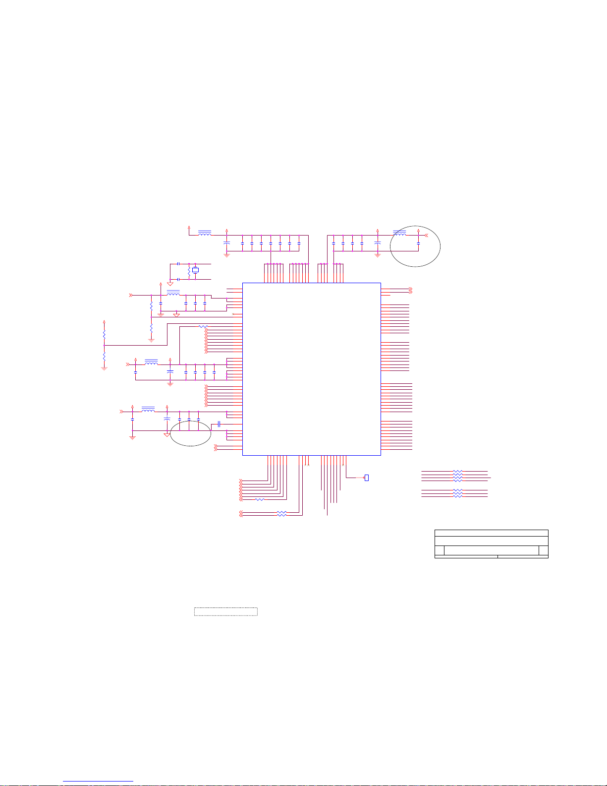
U7
C43.C44.C45 IC
盡量靠近
Near to Chip
A
RTD_2523
Friday, October 15, 2004
Title
Size Document Number
Rev
Date:
AHS
AVS
XO
RX2P
RX1P
RX1N
RX0P
RXCP
RXOIN1-
RXECKIN-
RXEIN3+
RXEIN0+
RXOIN0+
RXECKIN+
RXEIN2+
RXOIN0-
RXOIN1+
RXEIN1-
RXEIN3-
RXEIN2-
RXEIN0-
RXEIN1+
RXOIN2+
RXOIN3-
RXOCKIN-
RXOIN3+
RXOIN2-
RXOCKIN+
AG2P
AR3N
AR1P
AR2P
AR3P
AG1N
AR1N
AR2N
BG3N
BCLKP
BB1N
BB1P
BB2N
BB3N
BB3P
BG3P
BCLKN
BB2P
AG1P
AG2N
TCON5
TCON8
TCON10
XO
XI
XI
TCON5
FXDIO
TCON6
XSTB
TCON7
POL
TCON8
BXDIO
TCON9
YCLK
TCON10
YDIO
TCON11
YOE
TCON7
TCON9
TCON11
TCON6
R-
SOG
B-
B+
GR+
RX2N
RX0N
RXCN
PLL_GND
ADC_GND
AHS
AVS
3AVCC1
RTD_SCSB
2.5DVCC
3AVCC2
3PVCC
RESET
VBRI
RTD_SCLK
RTD_SDO/SDI
SDIO1
SDIO2
SDIO3
VOLUME
DDC_SCL
DDC_SDA
BLUE+
BLUE-
GREEN-
GREEN+
SOGIN
RED-
RED+
TXC+
TXC-
TX2+
TX2TX1+
TX1TX0+
TX0-
2.5DVCC
3PVCC
R2.5DVCCR3DVCC
TMDS_AVCC
ADC_VCC3AVCC1
3AVCC2 TMDS_AVCC
3DVCC
+
C59
22uF/16V
C37
0.1u/6
C63
0.1u/6
C39
0.1u/6
R56 1K/6
22/6R60
L12
FEB_0805
+
C53
22uF/16V
C49
0.1u/6
L19 FEB_0805
C45
0.1u/6
22/6R61
C57
0.1u/6
C61
0.1u/6
L14 FEB_0805
NCR72
C46
10uF/16V
L15 FEB_0805
22/6R62
C50
10uF/16V
C42
0.1u/6
C62
0.1u/6
C33 22pF/6
22/6R63
C56
0.1u/6
L13 FEB_0805
C54
0.1u/6
C48 22pF/6
22/6R64
C34
10uF/16V
C60
0.1u/6
C52
0.1u/6
R66 100/6
RTD2523
108
128
5450111
56
42
43
124
9
10
11
12
13
14
15
123
118
40
29
30
31
33
35
37
27
38
41
39
28
32
6
7
1
2
4
3
5
8
114
115
116
117
119
122
47
126
125
109
120
69
71
1214972
57
58
26
97
83
95
96
84
98
113
110
127
25
24
21
22
23
20
19
18
17
16
78
79
80
81
82
85
86
87
88
89
90
106
107
91
515253
55
59
60
61
62
63
64
65
66
67
68
73
74
75
76
77
104
93
102
103
101
100
94
99
92
36
34
105
46
444570
48
AR1N
2.5V Ground
SDIO[0]
SCLK
SCSB
RESET#
AHS
AVS
TCON[0]/VCLK
TMDS_TST/PWM1
TMDS_GND
TMDS_VDD
EXT_RES
TMDS_VDD
RX2P
RX2N
TCON[1]/V[7]
TCON[7]/V[4]
ADC_GND
ADC_VDD
B+
BSOG/ADC_TEST
GR+
ADC_GND
R-
ADC_VDD
ADC_GND
ADC_REFIO
ADC_GND
PLL_TEST1
PLL_TEST2
XO
XI
DPLL_VDD
DPLL_GND
APLL_VDD
APLL_GND
TCON[11]/V[0]
TCON[10]/V[1]
TCON[9]/V[2]
TCON[8]/V[3]
TCON[6]/V[5]
TCON[5]/V[6]
DDCSDA
DDCSCL2
DDCSDA2
3.3V Ground
3.3V Ground
2.5V Power
3.3V Power
3.3V Power
3.3V Power
3.3V Ground
3.3V Ground
3.3V Power
TMDS_VDD
2.5V Ground
3.3V Power
3.3V Power
3.3V Ground
3.3V Ground
2.5V Power
TCON[12]/COUT/PWM2
3.3V Power
PWM0/REFCLK
2.5V Power
TMDS_GND
RXCN
RX0N
TMDS_GND
RXCP
RX0P
TMDS_VDD
RX1N
RX1P
TMDS_GND
BR3N/TOCN
BR2P/TOBP
BR2N/TOBN
BR1P/TOAP
BR1N/TOAN
AB3P/TEDP
AB3N/TEDN
AB2P/TECLKP
AB2N/TECLKN
AB1P/TECP
AB1N/TECN
AR2N/TCON[1]
AR1P/TCON[0]
ACLKP/TEBP
TCON[2]/SDIO[3]/PWM2
TCON[3]/SDIO2]
TCON[4]/SDIO[1]
TCON[13]/COUT/PWM2
BB3P
BB3N
BB2P
BB2N
BB1P
BB1N
BCLKP
BCLKN
BG3P
BG3N
BG2P/TODP
BG2N/TODN
BG1P/TOCLKP
BG1N/TOCLKN
BR3P/TOCP
AR3N/TCON[6]
AG3P/TEAP
AG1N/TCON[8]
AR3P/TCON[7]
AG1P/TCON[9]
AG2N/TCON[10]
AG3N/TEAN
AG2P/TCON[11]
ACLKN/TEBN
ADC_VDD
G+
AR2P/TCON[5]
DDCSCL
2.5V Ground
2.5V Power
2.5V Ground
3.3V Ground
C55
0.1u/6
22/6R65
R53
NC
Y1
24.576MHz
C58
0.1u/6
C51
0.1u/6
C44
0.1u/6
R54
4.7K/6
R57
NC
R55
4.7K/6/NC
TP2
TEST POINT
1
C40
0.1u/6
C47
0.1u/6
C43
0.1u/6
C41
0.1u/6
NCR71
C38
0.1u/6
C64 0.1u/6
R58
4.7K/6
C35
0.1u/6
C36
0.1u/6
22/6R59
69
ViewSonic Corporation
Confidential - Do Not Copy VX710
Page 73
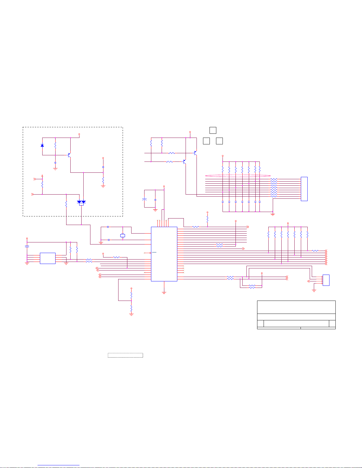
PARAMETER
EEPROM
B
C
TO BUTTON BOARD
Junction from
A change to B
R101,R103 net swap
less R94 to CN6 pin 11
E
2.0mm pitch
90° E&T
4607-11Pin
Reset circuit
Add Q20,R165,R166,C103,D32,D33
2004/6/16
DISPLAY
MCU & BUTTON
Friday, October 15, 2004
A
Title
Size Document Number
Rev
Date:
LED_R
LED_R
LED_G
IICSCL
IICSDA
TxD
RxD
LEFT
MENU
UP
RIGHT
SEL
PWR
PWR
LEFT
UP
RIGHT
MENU
DOWN
SEL
DOWN
PWR_SEL
LED_G
RESET
DDC_SDA
DDC_SCL
AVS
PANEL_PW12
Hot_Plug
STBY
MUTE
SDIO1
SDIO2
RTD_SCSB
RTD_SDO/SDI
SDIO3
RTD_SCLK
VRMT
PANEL_PW3
5DVCC
3AVCC1
VCPU
VCPU
VCPU
VCPU
VCC12
VCPU
VCPU
3DVCC
VCPU
3DVCC
VCPU
VCPU
3AVCC1
R78
10K/6
R120 NC
R125 100/6
R108 4.7K/6
R109 4.7K/6
R98 1K/6
R38
2K/6
R92 100/6
R99 1K/6
C77
0.1U/6
R88
33K/6
R85
33K/6
Q13
2N3906
2
13
R113
NC
R83 100/6
R82 4.7K/6
CN6
4501-10-10P-R
1
2
3
4
5
6
7
8
9
10
+
C84
22uF/16V
R39 4.7K/6
R87
33K/6
R80
2K/6
R40 4.7K/6
R115
4.7K/6
R81
2K/6
R100 1K/6
R89
33K/6
R165
NC/100K/6
U8
24LC16
1
2
3
4 5
6
7
8
A0
A1
A2
VSS SI
SCK
WP
VCC
Q12
2N3906
2
13
R101 1K/6
R90
33K/6
C103
NC/1U/16V
R102 220/6
R91
33K/6
D32
NC/ 1N4148
R114
4.7K/6
R103 220/6
R110
4.7K/6
R106
NC/82K/6
C76
0.1U/6
R112
NC
C85
0.1u/6
C75
0.1U/6
12
C81
0.1U/6
Y2
11.0592MHz
C82
0.1U/6
R96 1K/6
R111
4.7K/6
D33
NC/DAN202U
3
2
1
R95 1K/6
R116
4.7K/6
R142 NC
R41
6.8K/6
C88 10pF/6
R147
4.7K/6
C86
NC/1U/16V
C87 10pF/6 R164 22
R163
4.7K/6
JP1
HEADER 4
1
2
3
4
I1
MTV312M64
12
11
7
19
17
18
20
21
22
23
24
25
3
2
1
42
41
40
33
32
31
30
9
26
27
28
29
810
14
13
4
38
39
5
6
16
15
34
35
36
37
43
44
X1
X2
RESET
INT0/P3.2
P1.0
P1.1
P1.2
P1.3
P1.4
P1.5
P1.6
P1.7
P5.0
P5.1
P5.2
P5.3
P5.4
P5.5
P6.7
P6.6
P6.5
P6.4
P6.3
P6.1/AD1
P6.0/AD0
P3.1/TXD
P3.0/RXD
VCC
VSS
ISCL/P3.5/T1
ISDA/P3.4/T0
VDD3
DA9/HALFV
DA8/HLFHO
NC
NC
P6.2
P4.2
P5.6
DA7
P4.0
P4.1
HSYNC
VSYNC
R84
33K/6
C78
0.1U/6
R166
0/6
C79
0.1U/6
C80
0.1U/6
Q20
NC/2N3906
2
13
R93 4.7K/6
R97 1K/6
R79
10K/6
R124 100/6
70
ViewSonic Corporation Confidential - Do Not Copy VX710
Page 74
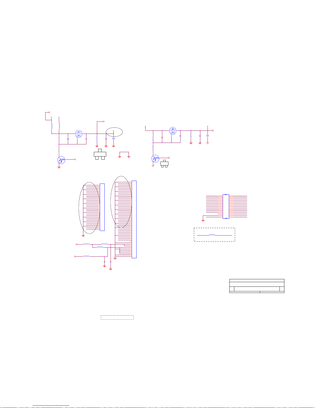
DG3
1S2
C
3
1
E
2
B
If panel is 3.3V LVDS IF, L30 must add the part 2004
/4/14
PANEL INTERFACE
<Doc>
<Title>
C
Friday, October 15, 2004
Title
Size Document Number
Rev
Date:
FXDIO
BB2P
RXEIN2-
RXOCKIN+
AG1N
BXDIO
AG2P
BCLKP
AR2N
BG3P
RXOIN2-
RXOIN1-
RXEIN0-
RXOCKIN-
YCLK
RXECKIN+
YDIO
YOE
RXECKIN-
RXOIN1+
AR3N
BCLKN
RXOIN0+
BB1P
AR1P
RXOIN3+
AG1P
RXEIN0+
BB2N
AR3P
RXEIN2+
XSTB
RXOIN0-
RXEIN3+
RXEIN1+
BB1N
RXEIN3-
BB3N
BG3N
RXOIN2+
AG2N
POL
AR2P
RXEIN1-
BB3P
RXOIN3-
AR1N
RXEIN3+
DGND
PANEL_5_12VCC
DGND
RXEIN1+
RXOIN0-
RXEIN0-
RXOIN2-
DGND
RXOIN2+
RXOIN3+
RXOCKIN-
RXECKIN+
RXEIN1-
RXOIN1-
DGND
RXOCKIN+
PANEL_5_12VCC
RXEIN0+
DGND
DGND
PANEL_5_12VCC
RXECKIN-
RXOIN1+
RXEIN2+
PANEL_3VCC
RXOIN3-
RXEIN3-
PANEL_5_12VCC
RXEIN2-
RXOIN0+
PANEL_5_12VCC
PANEL_PW12
5DVCC
PANEL_PW3
PANEL_3VCC
PANEL_3VCC
PANEL_5_12VCC
VCC12
GND
PANEL_5_12VCC
5DVCC
PANEL_3VCC
3DVCC
C68
2200P/6
L22
FEB_1206
C70
100U/16V
Q8 SI2301DS
3
1
2
C69
0.1U/6
R70
82K/6
C67
2200P/6
L21
NC
R68
10K/6
Q9
DTC144EUA
2
31
R67
82K/6
C74
NC/100U/16V
Q11 NC/DTC144EUA
2
31
R75
NC/82K/6
C73
NC/0.1U/6
R77
NC/10K/6
C72
NC/2200P/6
C71
NC/2200P/6
R76
NC/10K/6
Q10 NC/SI2301DS
3
1
2
L17
FEB_0805/NC
L18
FEB_0805/NC
J1
RSDS_CON30
1
2
3
4
5
6
7
8
9
10
11
12
13
14
15
16
17
18
19
20
21
22
23
24
25
26
27
28
29
30
1
2
3
4
5
6
7
8
9
10
11
12
13
14
15
16
17
18
19
20
21
22
23
24
25
26
27
28
29
30
C66
0.1U/6/NC
C65
0.1U/6/NC
J2
RSDS_CON50/NC
1
2
3
4
5
6
7
8
9
10
11
12
13
14
15
16
17
18
19
20
21
22
23
24
25
26
27
28
29
30
31
32
33
34
35
36
37
38
39
40
41
42
43
44
45
46
47
48
49
50
1
2
3
4
5
6
7
8
9
10
11
12
13
14
15
16
17
18
19
20
21
22
23
24
25
26
27
28
29
30
31
32
33
34
35
36
37
38
39
40
41
42
43
44
45
46
47
48
49
50
L20
FEB_0805/NC
L16
FEB_0805/NV
CN5
1841 30P
1
3
5
7
9
11
13
15
17
19
21
23
25
27
29
2
4
6
8
10
12
14
16
18
20
22
24
26
28
30
1
3
5
7
9
11
13
15
17
19
21
23
25
27
29
2
4
6
8
10
12
14
16
18
20
22
24
26
28
30
L30
NC/FEB_1206
71
ViewSonic Corporation
Confidential - Do Not Copy VX710
Page 75
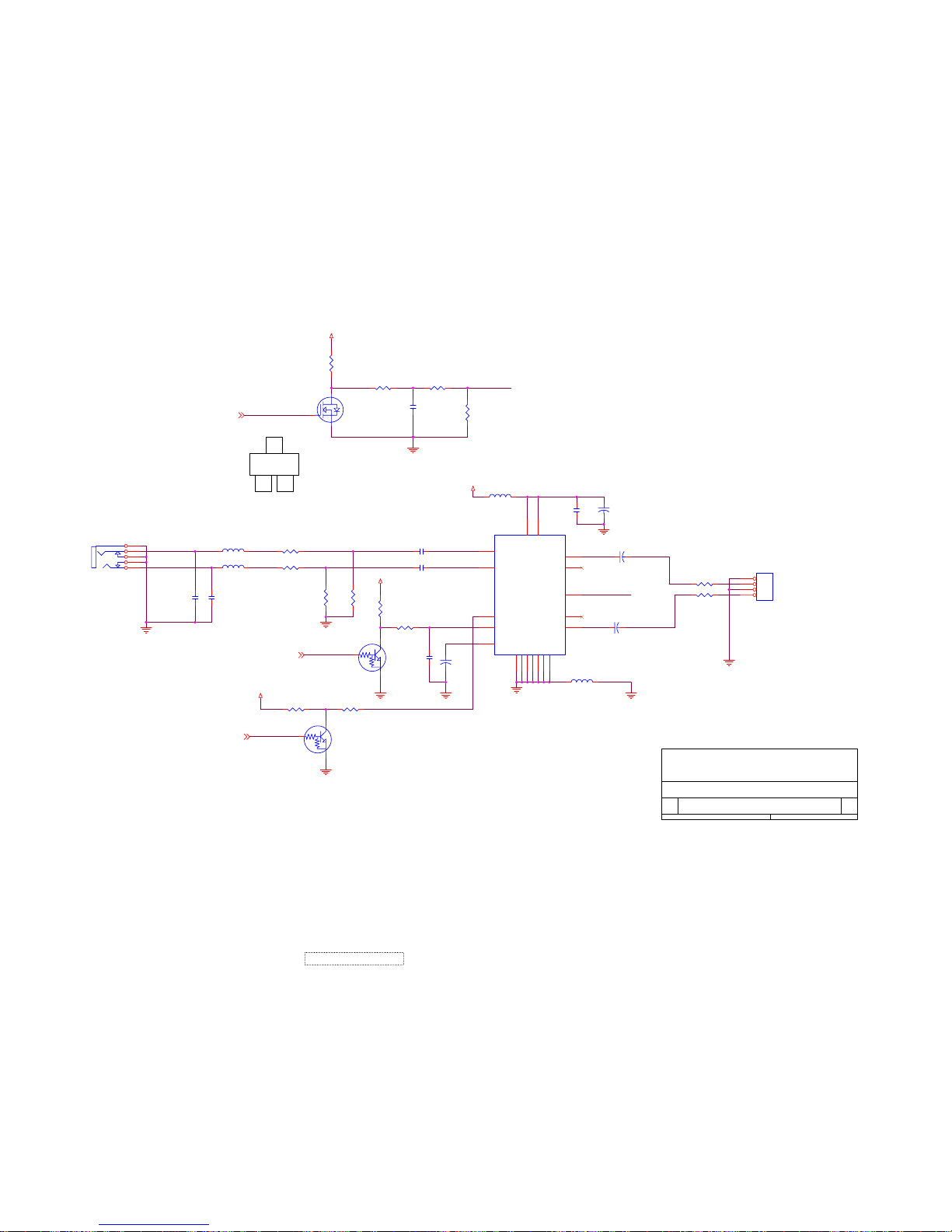
SPEAKER OUT
PC AUDIO-IN
123B
C
E
DISPLAY
AUDIO
Friday, October 15, 2004
A
Title
Size Document Number
Rev
Date:
L_LINE
Z0412
SPKOUTL
SPKOUTR
VOL
STBY
Z0416
MUTE
LIN_PC
Z0415
R_LINE
VOL
RIN_PC
STBY
MUTE
VOLUME
AGND
VCC12
AGND AGND
AGND
VCC12
VCC12
VCC12
AGND
AGND
AGND
AGND
AGND
L26 600/CX601T02001/NC
1 2
R128
1K/6/NC
C90
0.1U/6/NC
R138
10K/6/NC
Q15
SN7002E/NC
3
2
1
R133 100/6/NC
U9
TDA7496L/NC
4
9 5
6
7
17
1412
11
10
13
15
16
1231920
18
INL
INR VAROUT_L
VOLUME
VAROUR_R
OUTL
OUTRMUTE
STBY
SVR
GND
VS
VS
GND
GND
GND
GND
GND
GND
C92 0.47U/8/NC
C95
220P/6/NC
R139 10K/6/NC
R141 10K/6/NC
L25 600/CX601T02001/NC
1 2
C97
330U/16V/NC
C89
1U/8/NC
R140 10K/6/NC
C91
330U/16V
C96
220P/6/NC
C98
0.1U/8/NC
R130 10K/6/NC
JP2
4606-04-04P-R/NC
1
2
3
4
R134 CX201209805/8/NC
C99
330U/16V
R132 100/6/NC
Q16
DTC144EUA/NC
2
31
L24
BEAD/1206/NC
C93
330U/16V/NC
Q17
DTC143EUA/NC
2
31
L23 BEAD/1206/NC
R136
20K/6/NC
R137 CX201209805/8/NC
R129 10K/6/NC
R1313.9K/6/NC
R135
20K/6/NC
C94 0.47U/8/NC
J3
ZD005D100/NC
2
3
4
5
1
72
ViewSonic Corporation
Confidential - Do Not Copy VX710
Page 76
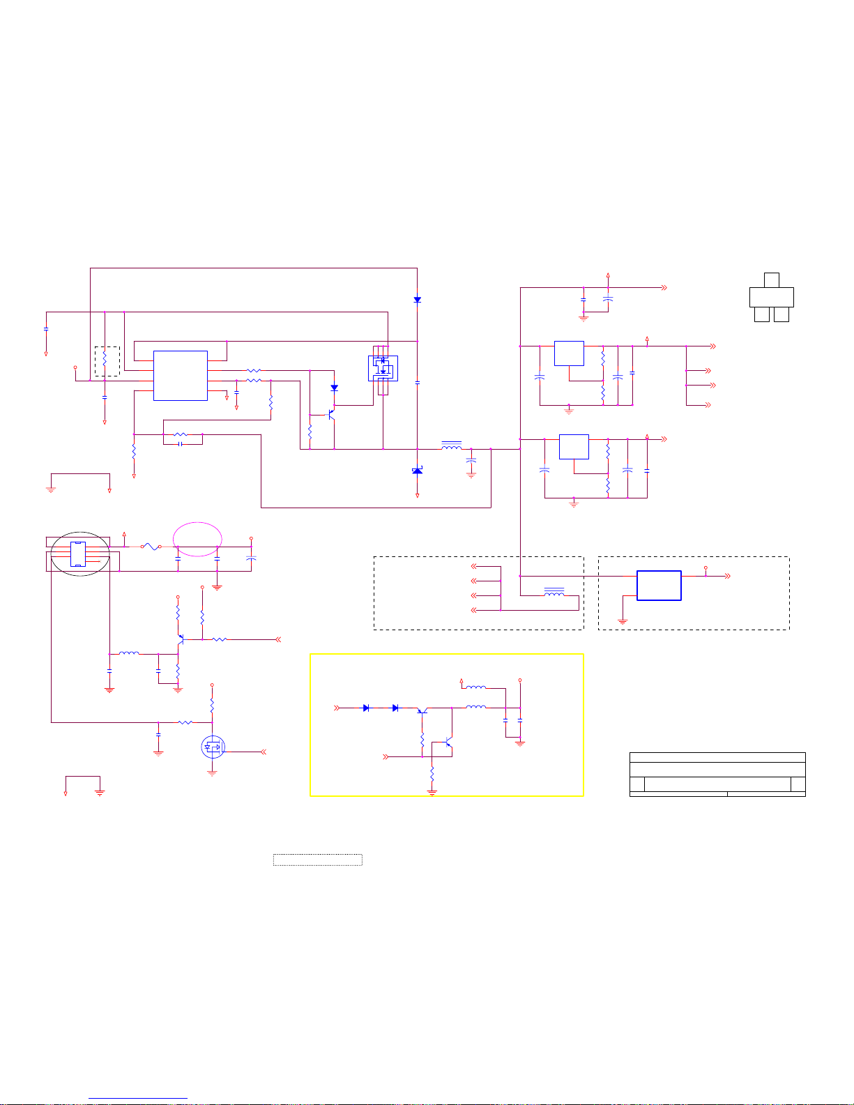
3
E12
Modify
ADC_ 3AVCC
LVDS_3AVCC
RTD 2.5DVCC
RTD 3DVCC
RTD 3PVCC
RTD 2.5DVCC
ADC_ 3AVCC
LVDS_3AVCC
RTD 3DVCC
RTD 3PVCC
3.3V-->2.5V regulator for 3.3V system power, no 5V 2004/4/14
R11:3K 1% ohm, R12:1K 1%
ohm -->output:5V;
R11:3.6K 1% ohm, R12:2.2K
1% ohm-->output 3.3V
R1,L1
POWER
<Title>
Friday, October 15, 2004
Title
Size Document Number
Rev
Date:
3DVCC
3AVCC2
5DVCC
3DVCC
3AVCC1
3PVCC
2.5DVCC
VBRI
VRMT
3AVCC1
3PVCC
3AVCC2
3DVCC
2.5DVCC
DSUB_5V
VCPU
3DVCC
GND
GND
2.5DVCC
GND
GND
GND
GND
3DVCC
GND
5DVCC
DGND
3DVCC
12V
VCC12
3DVCC
GND
3DVCC
2.5DVCC
VCC12
L3
10K/6
12
C8
0.1u/6
R11 3K/6 1%
Q2
MMST3906
3 2
1
C2
1u/6
R14
10K/6/NC
+
EC1
10uF/16V
R2
0/1206
U2
AIC1563
1
2
3
45
6
7
8
DC
DE
CF
GNDFB
VCC
IS
BOOST
C11
0.1U/6
R144
4.7K/6
Q3
MMST3906
Q4
SN7002E
3
2
1
C7
0.1u/6
C9
120p/6
EC4
330u/16V
D3
RB081L-20
1 3
R6
330/6 1%
D1
1SS355
R16
1K/6
C3
0.1u/6
C100
0.1u/6
R8
0/6
R9
1K/6
R4 47/6
U1 AIC1117CY
3
1
2
VIN
GND
VOUT
L28
CX201209805/8
C5
0.1u/6
C102
1U/6
R18 4.7K/6
L29
FEB/1206/NC
+
EC3
10uF/16V
R13 1K/6
+
EC2
10uF/16V
FUSE1
0
1 2
U3 AIC1117CY
3
1
2
VIN
GND
VOUT
C4
0.1u/6
U10
AIC1739/NC
3 1
2
VIN VOUT
GND
C12
0.1u/6
L2
47UH
12
+
EC6
10uF/16V
R15
200/6 1%
+
EC5
10uF/16V
R17
200/6 1%
C6
330u/16V
R3
200/6 1%
Q19
MMBT3906
C101
NC/6
R143
4.7K/6
D2
1SS355
C10 2200p/6
Q1
NDS9410A/SO
234 5
7681
D31
1N4148
R5 330K/6
L27
NC/CX201209805/8
D30
1N4148
CN1 CONN 4x2-R
4
5 6
1 2
3
8
Q18
MMBT3906
R12
1K/6 1%
R7
240K/6 1%
C1
0.1u/6
R10
10K/6
C13
1U/8
73
ViewSonic Corporation
Confidential - Do Not Copy VX710
Page 77
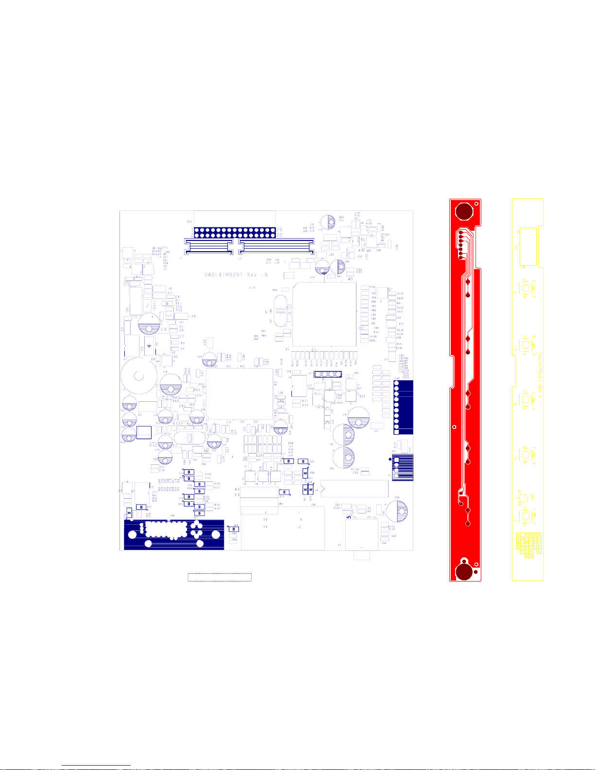
11. PCB Layout Diagrams
74
ViewSonic Corporation Confidential - Do Not Copy VX710
Main Board
Control Board
Page 78
*Readers Response*
Dear Readers:
Thank you in advance for your feedback on our Service Manual, which allows continuous improvement
of our products. We would appreciate your completion of the Assessment Matrix below, for return to
ViewSonic Corporation.
Assessment
Readers basic data:
After completing this form, please return it to ViewSonic Quality Assurance
metI tnellecxE dooG riaF daB
.1
.2
.3
tinU riaF daB
in the USA at facsimile
1-909-839-7943.
You may also e-mail any suggestions to the Director, Quality Systems & Processes
(marc.mau[email protected])
dooGtnellecxE
Precautions and Safety Notices
1.
8. Exploded Diagram and Exploded Parts List
7. Recommended Spare Parts List
Adjustment Procedure
2. Specification
5.
4. Circuit Description
3.
6. Troubleshooting Flow Chart
Front Panel Function Control Description
9. Block Diagram
10. Schematic Diagrams
11. PCB Layout Diagrams
Service Manual Content
Service Manual Layout
The form and listing
Name: Title:
Company:
Add.:
Tel:
E-mail:
Fax:
A. What do you think about the content of this Service Manual?
B. Are you satisfied with this Service Manual?
C. Do you have any other opinions or suggestions regarding this service manual?
7575
ViewSonic Corporation Confidential
-
Do Not Copy VX710
 Loading...