

Page 1

Service Manual
ViewSonic VX2739wm-1
VX2739wm-CN
Model No. VS12843
27” Color TFT LCD Display
(VX2739wm-1_VX2739wm-CN_SM Rev. 1a May. 2010)
ViewSonic 381 Brea Canyon Road, Walnut, California 91789 USA - (800) 888-8583
Page 2

Copyright
ViewSonic Corporation
VX2739wm-1
VX2739wm-CN
CONFIDENTIAL – DO NOT COPY
i
Copyright © 2010 by ViewSonic Corporation. All rights reserved. No part of this
publication may be reproduced, transmitted, transcribed, stored in a retrieval system, or
translated into any language or computer language, in any form or by any means,
electronic, mechanical, magnetic, optical, chemical, manual or otherwise, without the prior
written permission of ViewSonic Corporation.
Disclaimer
ViewSonic makes no representations or warranties, either expressed or implied, with
respect to the contents hereof and specifically disclaims any warranty of merchantability or
fitness for any particular purpose. Further, ViewSonic reserves the right to revise this
publication and to make changes from time to time in the contents hereof without obligation
of ViewSonic to notify any person of such revision or changes.
Trademarks
Optiquest is a registered trademark of ViewSonic Corporation.
ViewSonic is a registered trademark of ViewSonic Corporation.
All other trademarks used within this document are the property of their respective owners.
Product disposal at end of product life
The lamp in this product contains mercury. Please dispose of in accordance with local, state
or federal laws.
Revision History
Revision SM Editing Date ECR Number Description of Changes Editor
1a 5/7/2010 Initial Release Eden Chang
Page 3

TABLE OF CONTENTS
ViewSonic Corporation
VX2739wm-1
VX2739wm-CN
CONFIDENTIAL – DO NOT COPY
ii
1. Precautions and Safety Notices.......................................................................................4
2. Specification .....................................................................................................................8
3. Front Panel Function Control Description ...................................................................17
4. Circuit Description...........................................................................................................20
5. Adjusting Procedure .......................................................................................................22
6. Trouble Shooting Flow Chart..........................................................................................68
7. Block Diagrams ..............................................................................................................74
8. Schematic Diagrams ......................................................................................................75
9. PCB Layout Diagrams ...................................................................................................78
10. Exploded Diagram And Spare Parts List .....................................................................79
11. Recommended Spare Parts List .................................................................................80
Page 4
1. Precautions and Safety Notices
ViewSonic Corporation
VX2739wm-1
VX2739wm-CN
CONFIDENTIAL – DO NOT COPY
4
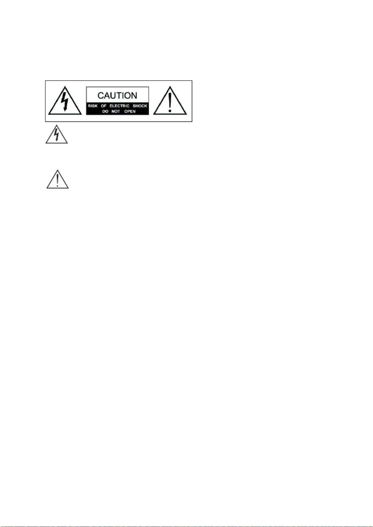
Safety Instructions
The symbol is intended to alert the user to presence of un-insulated
“Hazardous Voltage” within the product’s enclosure that may be of sufficient
magnitude to constitute a risk of electric shock to persons.
This symbol is intended to alert the user that improper use of the product
may result in product malfunction. The user should pay attention to avoid
accidents or unnecessary problems.
Wet Location
Apparatus shall not be exposed to dripping or splashing and that no objects filled
with liquids, such as vases, shall be placed on the apparatus.
Outdoor Use
WARNING: To reduce the risk of fire or electric shock, do not expose this
apparatus to rain or moisture.
Disconnect Device - The Mains Plug or An Appliance Coupler
The mains plug or an appliance coupler is used as the disconnect device for
disconnection from the mains, the disconnect device shall remain readily
operable.
Safety
Operate the Monitor on 100V and 120 V AC only.
Use the AC power cord specified by ViewSonic and suitable for the voltage where
you use it.
The plug is designed, for safety purposes, to fit into the wall outlet only one way.
If you are unable to insert the plug fully into the outlet, contact your dealer.
If any liquid or solid object should fall inside the cabinet, stop operating, unplug the
Monitor immediately and have it checked by qualified service technician.
If you will not be using the Monitor for a long time, disconnect the power by pulling
Page 5
the plug itself. Do not pull on the cord.
ViewSonic Corporation
VX2739wm-1
VX2739wm-CN
CONFIDENTIAL – DO NOT COPY
5
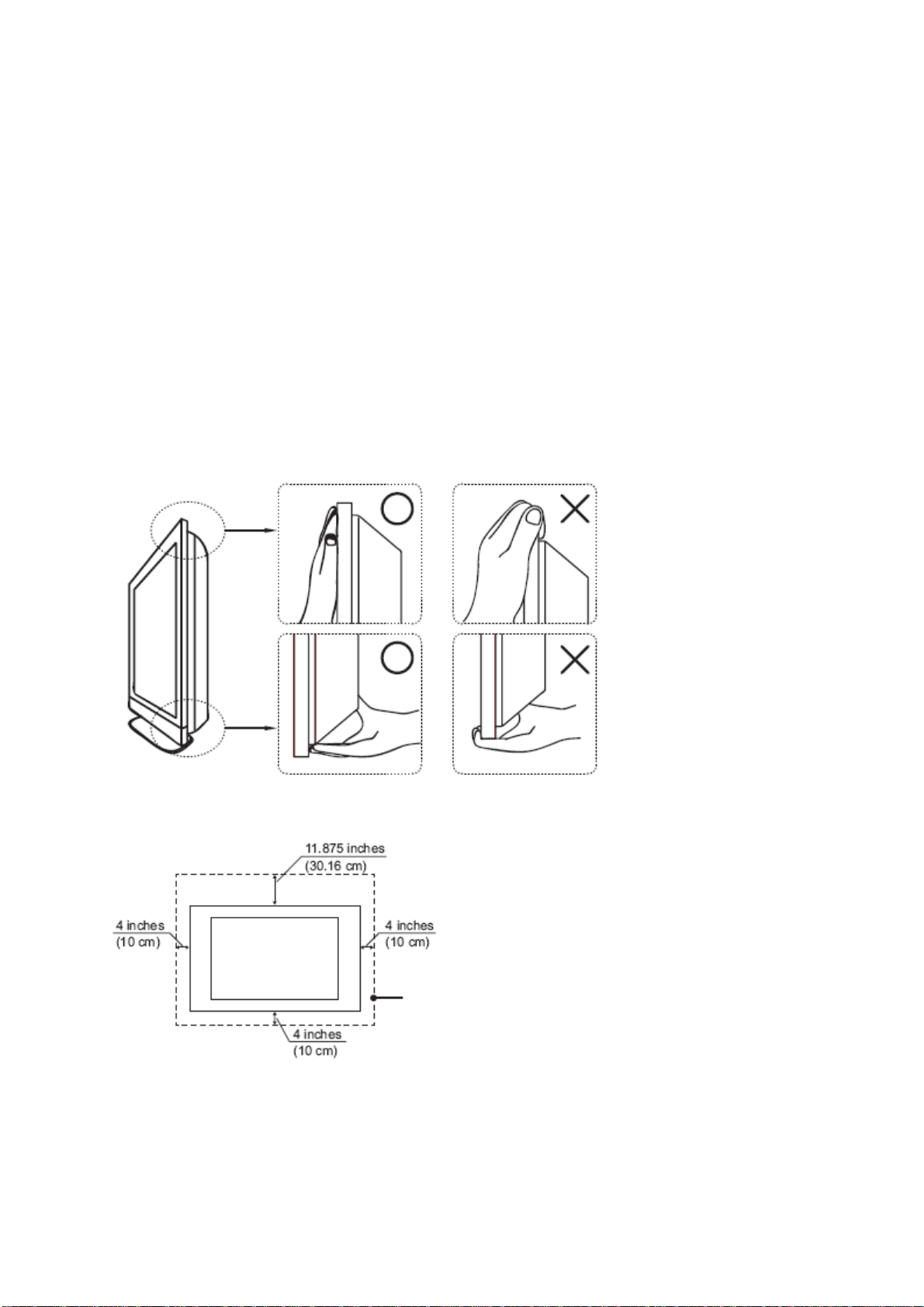
Carrying The LCD Monitor
To prevent dropping the Monitor and causing serious injury, you must follow these
guidelines:
Disconnect all cables before carrying the Monitor.
Carrying the large size Monitor requires at least two or three people.
When you carry the Monitor, place your hands as illustrated and hold it securely.
Do not put stress on the LCD panel and the frame around the screen.
When carrying the Monitor, do not subject it to shocks, vibration, or excessive
force.
When lifting or moving the Monitor, hold it securely from the bottom. Place your
palm directly under the panel.
Installed on the wall
Installed with stand
Page 6
ViewSonic Corporation
VX2739wm-1
VX2739wm-CN
CONFIDENTIAL – DO NOT COPY
6
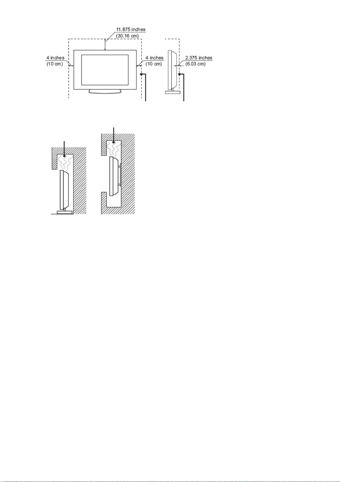
Leave at least this space around the set. Do not install the Monitor set as follows:
Air circulation is blocked.
Broken pieces
Do not throw anything at the LCD.
Doing so may break the screen glass and cause serious injury.
If the surface of the LCD cracks, unplug the AC power cord before touching the
LCD. Otherwise electric shock may result.
Handling of broken glass and liquid crystal leakage
If the LCD panel gets damaged, crystalline liquid leakage may occur, or scattered
broken glass may result.
Do not touch broken glass or crystalline liquid which is toxic, with bare hands as
cuts, poisoning or skin irritation may occur.
Also do not glass fragments or leaked crystalline liquid get into your eyes or mouth.
Should either contacted your eyes or mouth, rinse the contacted area thoroughly
with water and consult your doctor.
Note
This television includes a QAM demodulator, which should allow you to receive
unscrambled digital cable television programming via subscription service to a
cable service provider.
The type of programming and signal provided by your cable service provider will
affect the availability of digital cable television programming in your area.
Page 7
ViewSonic Corporation
VX2739wm-1
VX2739wm-CN
CONFIDENTIAL – DO NOT COPY
7
2. Product Specification
2.1 Product definition
Product Name ViewSonic VX2739WM
Model Number VS12843
English
French
German
Spanish
Italian
OSD Languages
Finnish
Russian
Japanese
Korean
Traditional Chinese
Simplified Chinese
TFT LCD Panel and Model # 1st source : CMO M270H1-L01
Scalar TSUMO88GDI-LF-1
Input Signal D-Sub /DVI/HDMI
Sync Compatibility Separate Sync / Composite Sync / SOG
Adapter Internal Power Board
Power Cable (Refer to APPENDIX B) Yes
15 pin mini D-SUB Analog Cable (1.8 m,
black), with PC 2001.
Yes
(Detached cable; refer the Appendix A)
DVI-D Cable(1.8m, black) with PC 2001
(refer to Appendix A)
Audio Cable(1.8m, black) with PC 2001 Yes
MIC Cable(1.8m, black) with PC 2001 No
USB Cable (V2.0)
(1.8m, black) with PC 2001
Yes
Yes
Page 8

2.2 Specification
ViewSonic Corporation
VX2739wm-1
VX2739wm-CN
CONFIDENTIAL – DO NOT COPY
8
Dimensions (with
647 mm (W) x 490 mm (H) x 250 mm (D)
stand)
Physical(W)x(H)x(D)
Weight 6.8 kg
LCD 27" Color active matrix TFT LCD
Pane CMO M270H1-L01
Contrast Ratio 1200 :1 (Typ.)
Display area 597.89 mm (H) x 336.31 mm (V)
Pixel Pitch 0.3114 mm (H) x 0.3114 mm (V) pixel
Native Resolution 1920 x 1080
Speaker Output 2W x 2
2.3 Front View and Rear View
N
Name Photo Materials Piece Texture Color Scheme
o.
POLISH #
1 Front
ABS 1
Viewsonic black
8000
Mold-Tech
MT-11020
2 Back
ABS 1
Viewsonic black
(Logo is
POLISH #
8000)
Page 9
Power
ViewSonic Corporation
VX2739wm-1
VX2739wm-CN
CONFIDENTIAL – DO NOT COPY
9
3
button ring
ABS 1 electroplate silver
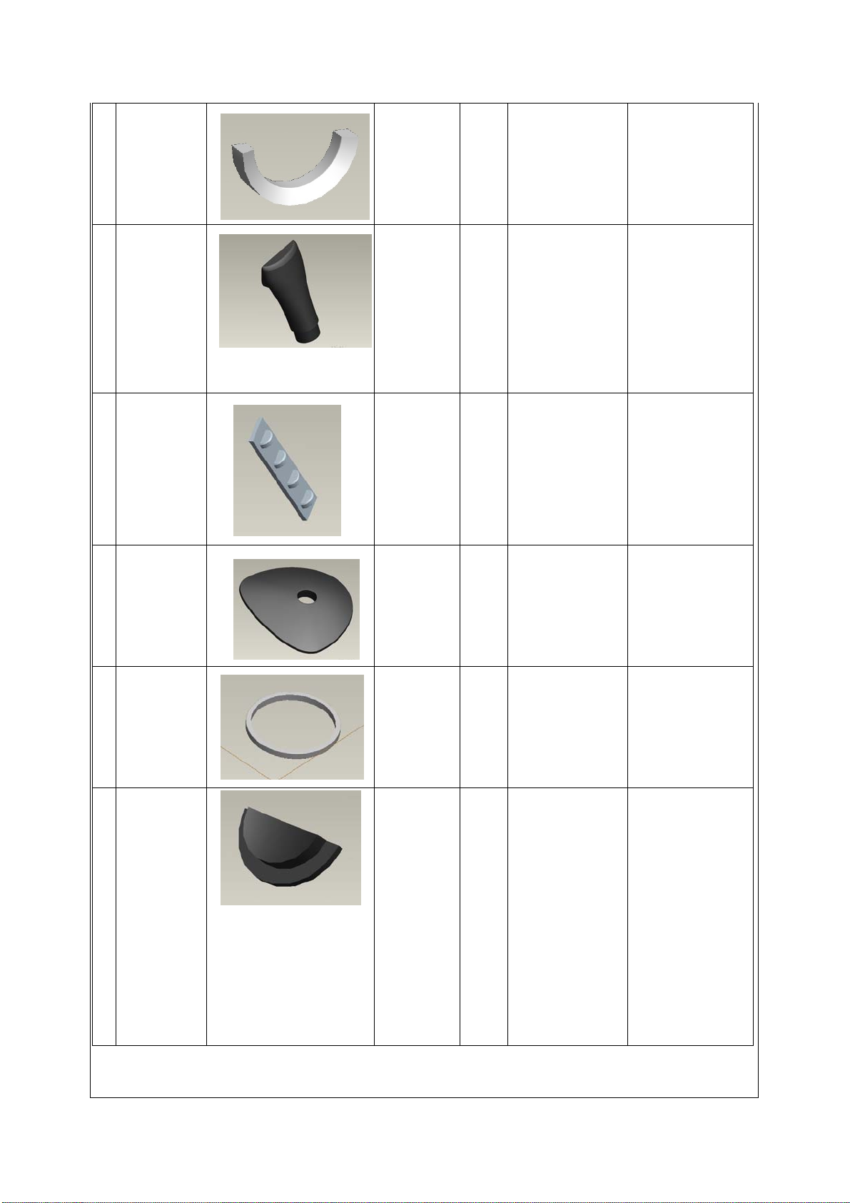
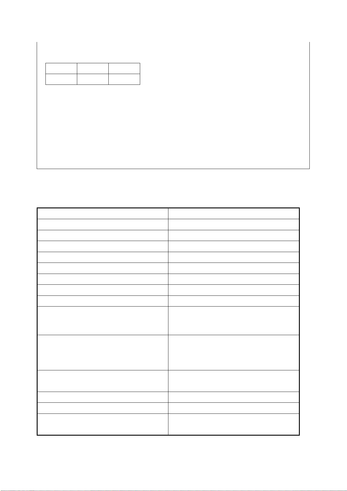
4 Neck
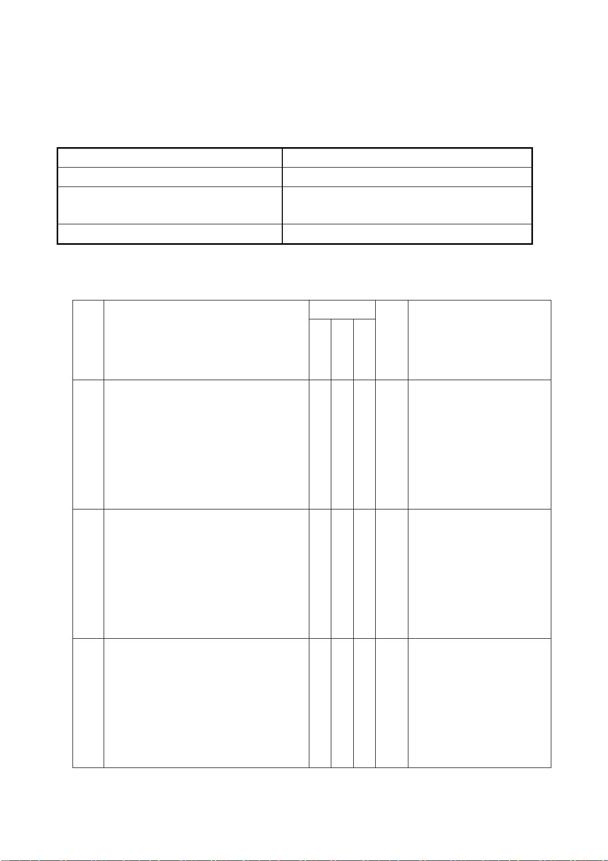
5 Key button
6 base
ABS 1
Viewsonic black
8000
Mold-Tech
POLISH #
ABS 1
Viewsonic black
MT-11010
POLISH #
ABS 1
Viewsonic black
8000
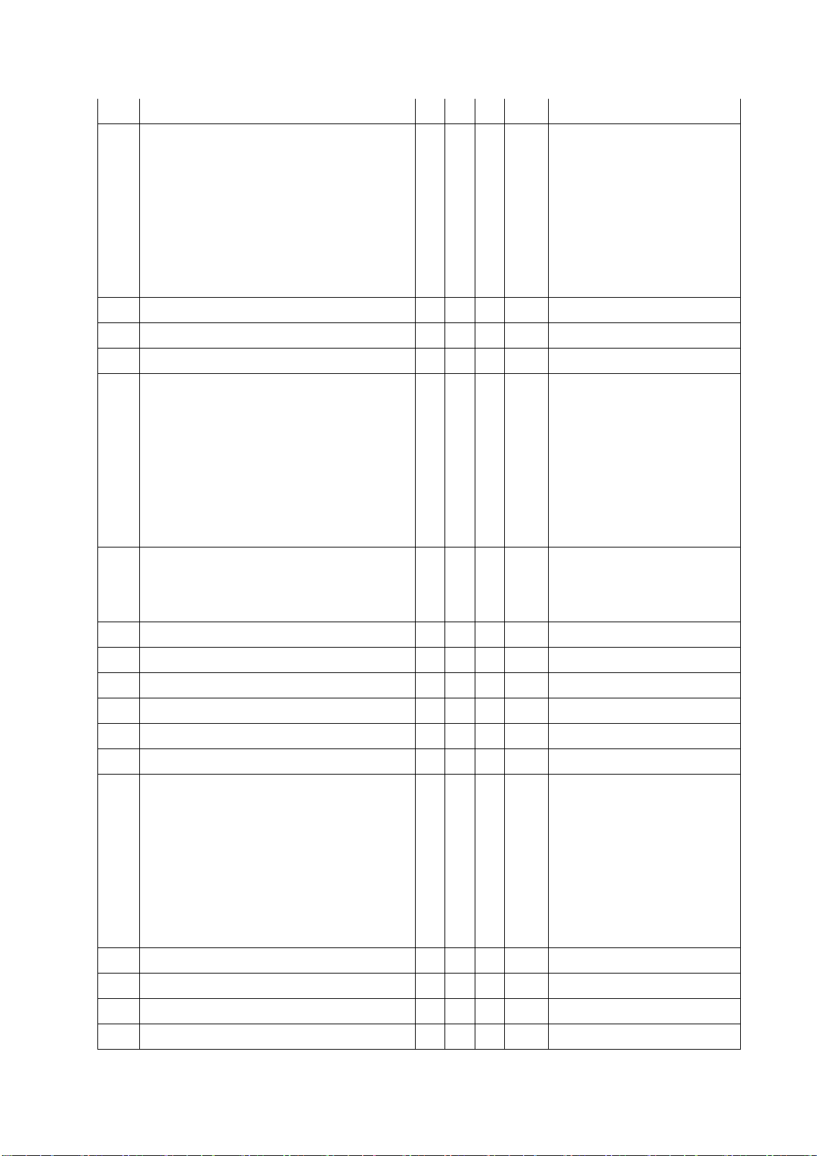
7 base_ring
Power
8
button
ABS 1 electroplate silver
1. Black by
painting at
core-side
surface.
Transluce
nt
1
POLISH #
8000
2.Power icon by
Lacer-engravin
PC
g and then
painting
pantone # 427C
3. Blue LED.
Page 10
ViewSonic Corporation
VX2739wm-1
VX2739wm-CN
CONFIDENTIAL – DO NOT COPY
10
** ViewSonic Black_matt
L* a* b*
27.47 -0.06 -0.8
*CIE1976; Polish level = 1200; Follow the Equipment in ViewSonic Lab
*1. The reference for the cabinet components is the color chip provided by ViewSonic.
*2. The color difference between any two panel head cabinet components shall be ∆E <0.8, in the 1976
CIE L*a*b Colorspace.
*3. The color difference between any two base cabinet components shall be ∆E <0.8, in the 1976 CIE
L*a*b Colorspace.
2.4 Audio Interface (Speaker Specification)
Line input signal 1.0 Vrms @1kHz
Line input impedance 10 Kohm
Maximum Amp power output (Watt) 2.4 W @ SPKVDD=5V 4OHM
Amp -THD < 10 % THD @1kHz
Speaker Power rating(Ω/Watt) 4Ω/ 2 W
Signal to Noise Ratio 50 db
Frequency response Fo – 20kHz
SPL. 91 dB (at 0.1w/0.1m)
FO 820 Hz
1. 3.5 mm stereo jack
Line input connection
2. HDMI
There should be no audible vibration
Vibration
resonance at volume=100% & any
Freq.
There should be no affect on the screen
Screen image
image stability under any conditions
Connector PC99 requirement Audio in Lime Green pantone # 577C
Cable type / length 3.5mm stereo cable / 1.8m length
Audio DPMS
Speakers stay off when the rest of the
monitor is in power saving
Page 11
ViewSonic Corporation
VX2739wm-1
VX2739wm-CN
CONFIDENTIAL – DO NOT COPY
11
2.5 Electrical Requirement
Horizontal / Vertical Frequency
Horizontal Frequency 24 – 83 KHZ
Vertical Refresh Rate 50 – 76 HZ
Maximum Pixel Clock Analog : 210 MHz
Digital : 180 MHz
Sync Polarity Independent of sync polarity.
Support Timing Table
Item Timing
640 x 350 @ 70 Hz, 31.5 KHz v v v v DMT.
1.
640 x 400 @ 60 Hz, 31.5 KHz v v v v DMT
2.
Analog
Composite
Separated
SOG
Digital - TMDS
Remark
For Separated、 SOG and
Composite sync, switch
640x350@70,640x400@70,
and720x400@70 by [1]+[2]
short cut key ( primary =
720x400@70)
For Separate, Composite
and SOG sync, switch
640x400@60Hz and
640 x 400 @ 70 Hz, 31.5 KHz v v v v DMT
3.
640x480@60Hz by [1]+[2]
short cut key (primary =
640x480@60Hz)
For Separated、 SOG and
Composite sync, switch
640x350@70,640x400@70,
and720x400@70 by [1]+[2]
short cut key ( primary =
720x400@70)
Page 12
4. 640 x 480 @ 50 Hz, 24.7 KHz v v v CVT
ViewSonic Corporation
VX2739wm-1
VX2739wm-CN
CONFIDENTIAL – DO NOT COPY
12
640 x 480 @ 60 Hz, 31.5 KHz v v v v DMT
For Separate, Composite
and SOG sync, switch
5.
640x400@60Hz and
640x480@60Hz by [1]+[2]
short cut key (primary =
640x480@60Hz)
6. 640 x 480 @ 67 Hz, 35 KHz v v v v For MAC
7. 640 x 480 @ 72 Hz, 37.9 KHz v v v v DMT
8. 640 x 480 @ 75 Hz, 37.5 KHz v v v v DMT
720 x 400 @ 70 Hz, 31.5 KHz v v v v DMT
For Separated、 SOG and
Composite sync, switch
9.
640x350@70,640x400@70,
and720x400@70 by [1]+[2]
short cut key ( primary =
720x400@70).
720 x 480 @ 60 Hz, 31.5 KHz v v v v DTV, For Analog sync, the
10.
information OSD shows
640x480
11. 720 x 576 @ 50 Hz, 31.3 KHz v v v v DTV
12. 800 x 600 @ 56 Hz, 35.2 KHz v v v v DMT
13. 800 x 600 @ 60 Hz, 37.9 KHz v v v v DMT
14. 800 x 600 @ 72 Hz, 48.1 KHz v v v v DMT
15. 800 x 600 @ 75 Hz, 46.9 KHz v v v v DMT
16. 832 x 624 @ 75 Hz, 49.7 KHz v v v v MAC
1024 x 768 @ 50 Hz, 39.6 KHz v v v v CVT
For Separated and
Composite sync, Switch
17.
1024x768@50Hz and
1280x768@50Hz by [1]+[2]
short cut key (primary =
1024x768@50Hz)
18. 1024 x 768 @ 60 Hz, 48.4 KHz v v v v DMT
19. 1024 x 768 @ 70 Hz, 56.5 KHz v v v v DMT
20. 1024 x 768 @ 72 Hz, 58.1 KHz v v v v DMT
21. 1024 x 768 @ 75 Hz, 60 KHz v v v v DMT;
Page 13
For Separated , Composite
ViewSonic Corporation
VX2739wm-1
VX2739wm-CN
CONFIDENTIAL – DO NOT COPY
13
and SOG,
Switch 1280x768@75Hz
and 1024x768@75Hz by
[1]+[2] short cut key
(primary =
1280x768@75Hz)
22. 1024 x 768 @ 75 Hz, 60.2 KHz v v v v For MAC
23. 1152 x 864 @ 75 Hz, 67.5 KHz v v v v DMT
24. 1152 x 870 @ 75 Hz, 68.7 KHz v v v v For MAC
25. 1152 x 900 @ 67 Hz, 62.5 KHz v v v v For SUN
26. 1280 x 720 @ 50 Hz, 37.5 KHz v v v v DTV
27. 1280 x 720 @ 60 Hz, 45 KHz v v v v DTV
1280 x 768 @ 50 Hz, 39.6 KHz v v v v DMT
For Separated and
Composite sync, Switch
28.
29.
30.
1024x768@50Hz and
1280x768@50Hz by [1]+[2]
short cut key (primary =
1024x768@50Hz)
1280 x 768 @ 60 Hz, 47.8 KHz v v v v DMT;
For Composite and SOG,
Switch 1280x768@60Hz
and 1360x768@60Hz by
[1]+[2] short cut key
(primary =
1280x768@60Hz)
1280 x 768 @ 75 Hz, 60.3 KHz v v v v DMT;
For Separated , Composite
and SOG,
Switch 1280x768@75Hz
and 1024x768@75Hz by
[1]+[2] short cut key
31. 1280 x 800 @ 60 Hz, 49.7 KHz v v v v DMT
32. 1280 x 800 @ 75 Hz, 62.8 KHz v v v v DMT
33. 1280 x 960 @ 50 Hz, 49.4 KHz v v v v DMT
(primary =
1280x768@75Hz)
Page 14
34. 1280 x 960 @ 60 Hz, 60.0 KHz v v v v DMT
ViewSonic Corporation
VX2739wm-1
VX2739wm-CN
CONFIDENTIAL – DO NOT COPY
14
35. 1280 x 960 @ 75 Hz, 75.2 KHz v v v v DMT
36. 1280 x 1024 @ 50 Hz, 52.7 KHz v v v v DMT
37. 1280 x 1024 @ 60 Hz, 64 KHz v v v v DMT
38. 1280 x 1024 @ 75 Hz, 80 KHz v v v v DMT
1366 x 768 @ 60 Hz, 47.7 KHz v v v v DMT
For Composite and SOG,
Switch 1280x768@60Hz
39.
and 1360x768@60Hz by
[1]+[2] short cut key
(primary =
1280x768@60Hz)
40. 1440 x 900 @ 60 Hz 55.9 KHz v v v v DMT
41. 1440 x 900 @ 75 Hz 70.6 KHz v v v v DMT
1400 x 1050 @ 60 Hz 65.3 KHz v v v v DMT;
For Separated , Composite
and SOG,
Switch 1400x1050@60Hz
42.
and 1680x1050@60Hz by
[1]+[2] short cut key
(primary =
1680x1050@60Hz)
43. 1400 x 1050 @ 75 Hz 82.3 KHz v v v v DMT
44. 1600 x 1200 @ 60 Hz 75.0 KHz v v v v DMT
45. 1680 x 1050 @ 60 Hz 64.7 KHz v v v v DMT
1680 x 1050 @ 60 Hz 65.3 KHz v v v v DMT;
For Separated , Composite
and SOG,
Switch 1400x1050@60Hz
46.
and 1680x1050@60Hz by
[1]+[2] short cut key
(primary =
1680x1050@60Hz)
47. 1920x1080 @ 60 Hz 67.5 KHz v v v v DMT
48. 480i @ 60 Hz
9
49. 480p @ 60 Hz 9 9 9 9
50. 576i @ 50 Hz
9
51. 576p @ 50 Hz 9 9 9 9
Page 15

52. 720p @ 50 Hz 9 9 9 9
ViewSonic Corporation
VX2739wm-1
VX2739wm-CN
CONFIDENTIAL – DO NOT COPY
15
53. 720p @ 60 Hz 9 9 9 9
54. 1080i @ 50 Hz
55. 1080i @ 60 Hz
56. 1080p @ 50 Hz 9 9 9 9
57. 1080p @ 60 Hz 9 9 9 9
*1. Tolerance ±2KHz. (if no over lapping issue)≧
*2. Any timing not in the list, it should display as normal or show on “OUT OF RANGE” OSD
message without blanking
9
9
Page 16
3. Front Panel Function Control Description
ViewSonic Corporation
VX2739wm-1
VX2739wm-CN
CONFIDENTIAL – DO NOT COPY
16
3.1 Front Panel Hardware Controls
Power Switch AC Power Switch on the back cover
Soft Power Switch on the front bezel
Power LED (Front Head) Blue – ON
Amber – Active Off
Dark = Soft Power Switch OFF
Front Panel Controls (Head)
[ 1 ] [ 2 ] [ ] [▲] [▼]
[ ] Power
[ 1 ] Button 1
[ 2 ] Button 2
[▲] Up arrow button
[▼] Down arrow button
Note: Power Button, Button 1 and Button 2
must be one-shot logic operation. (i.e. there
should be no cycling)
Reaction Time OSD must fully appear within 0.5s after
pushing Button 1
3.2 Short Cuts Function from the button
[1] Main Menu
(refer to segment 4-6-3)
[2] Input toggle (Analog or DVI or HDMI; refer to refer to
EDID Text)
[▼] To immediately activate Audio Adjust menu.
[▲] To immediately activate Contrast / Brightness OSD
Menu.
[▼]+ [▲] 1. In the Audio mode, recall both of Volume and Mute
to default without OSD message.( Under Volume
adjust sub-menu, recall Volume to default without
OSD message.)
2. In the BT / CR mode, recall both Contrast and
Brightness to default in its menu without OSD
message. (Under Contrast or Brightness adjust
sub-menu, recall Contrast or Brightness to its default
without OSD message.)
* While OSD menu off, recall CR/ BT/ Audio volume
Page 17
and mute to default without OSD message
ViewSonic Corporation
VX2739wm-1
VX2739wm-CN
CONFIDENTIAL – DO NOT COPY
17
[1] + [2] Toggle 720x400 and 640x400 mode when input
720x400 or 640x400 mode
* Default = 720 x 400
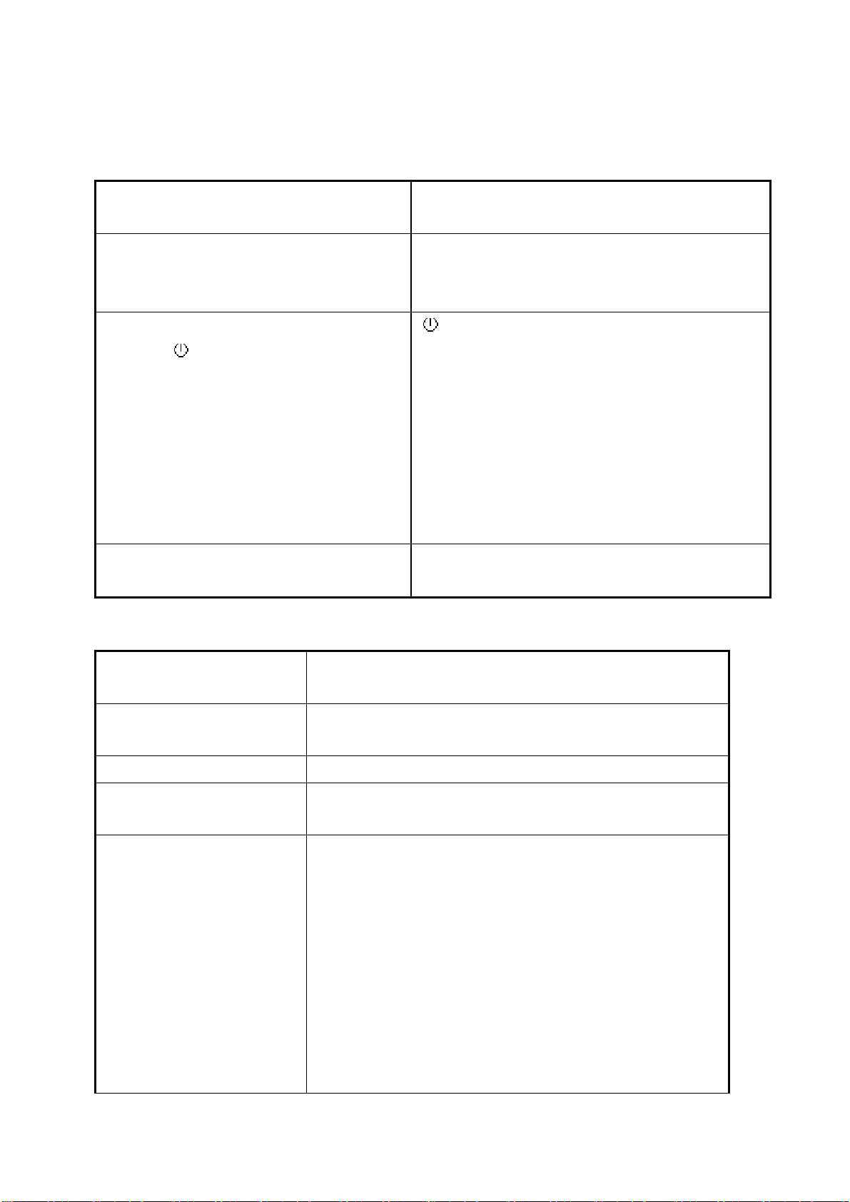
[1] + [▼] + [▲]
(Keep pushing 5 sec)
White Balance
1. It will not shown on user’s guide
2. OSD message as below,
(Image = no blanking)
3. Recommend environment
3.1. Optical (Best) input timing = 640 x 480 @
60Hz;
Following timing modes also
recommended,
800 x 600 @ 60 Hz
1024 X 768 @ 60 Hz
3.2. Pattern as below,
[1] + [▲] OSD Lock / Unlock (refer to segment 4-6-4)
[1] + [▼] Power Lock / Unlock (refer to segment 4-6-5)
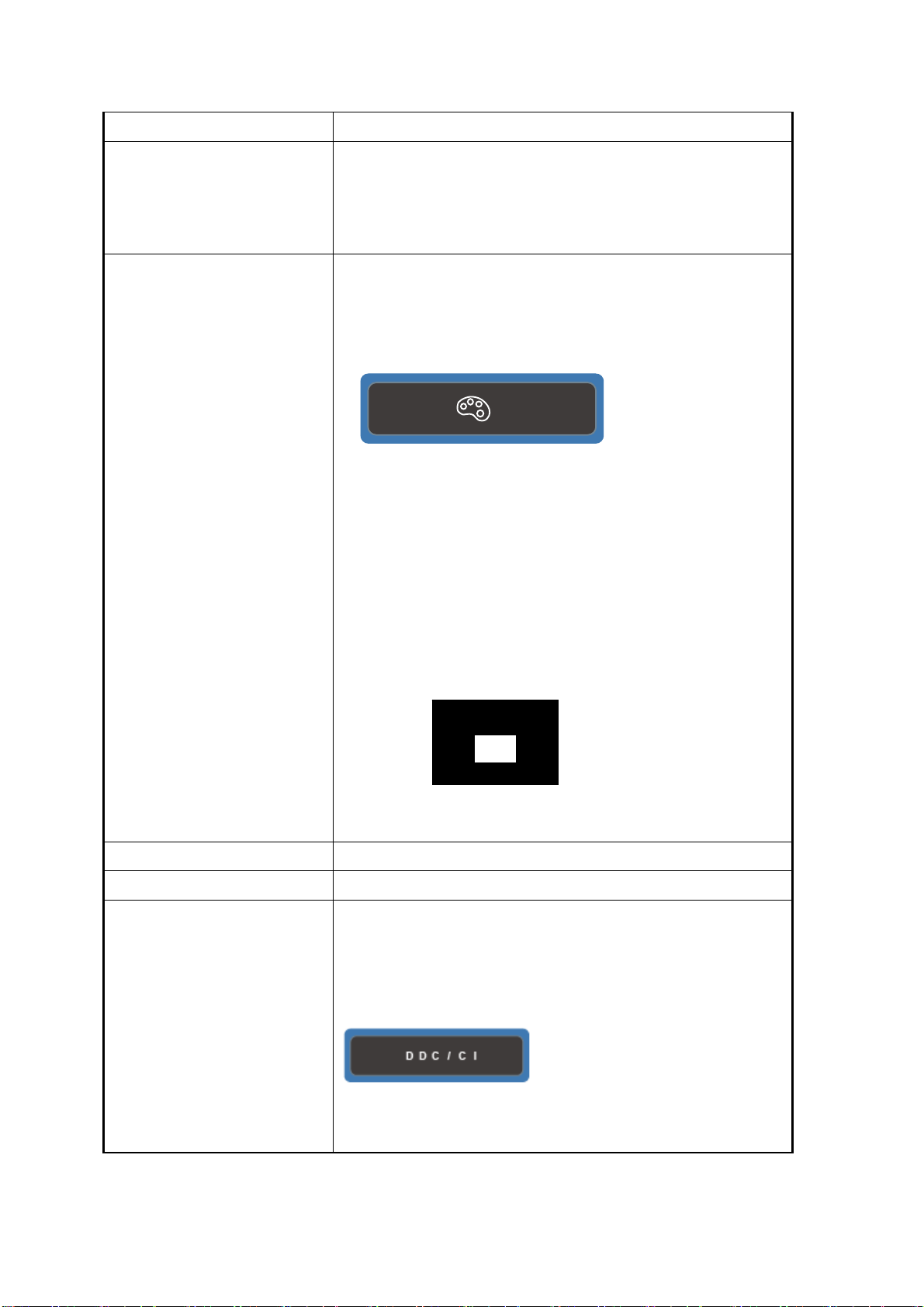
[2] + [▼] Toggle DDC/CI and DDC/2B (DDC/CI enable/disable)
and show following message for 3 seconds,
When switch to DDC/CI
When switch to DDC/2B
Page 18

ViewSonic Corporation
VX2739wm-1
VX2739wm-CN
CONFIDENTIAL – DO NOT COPY
18
Default = DDC/CI
Signal + [2] + [ ] Factory Mode
Remark : All the short cuts function are only available while OSD off
Page 19
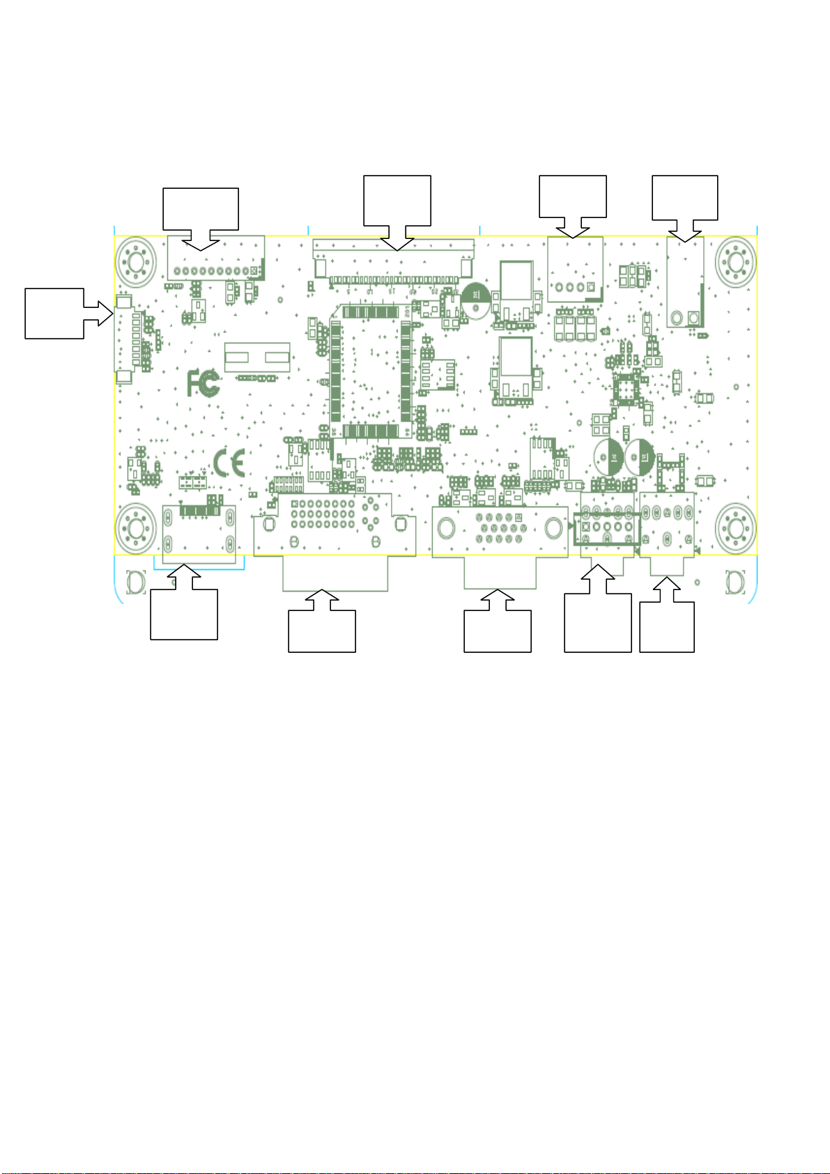
4. Circuit Description
ViewSonic Corporation
VX2739wm-1
VX2739wm-CN
CONFIDENTIAL – DO NOT COPY
19
CON3
CON1
CON5 CON6
J6
CON7
CON8 CON2
J4 or
J7
J3
Power Circuit:
Power board provided +5VD(CON1.1~CON1.2) and +5V (CON3~CON4),Which
+5V is for system and LCD Panel,+5VD provided for Audio AMP.
At AC power on status,Power off mode and standby mode,Power source only
provided +5V to TSUMO88GDI,Monitor total power consumption will be less the
1W.
The status for +5VD and +5V as below:
+5V will provide:
1. via Q4、Q3:VLCD(for LCD panel)
2. via U9 transferred to +3.3V(for TSUMO88GDI、audio AMP and system related
parts)
3. via U9 transferred to +1.8V(for TSUMO88GDI)
Page 20

+5VD will provide:
ViewSonic Corporation
VX2739wm-1
VX2739wm-CN
CONFIDENTIAL – DO NOT COPY
20
1. via Q3:+5VA(for audio AMP)
2. via J6 to USB HUB(for GL805G)
Backlight Control:
CON1.9 is inverter on/off control pin,which 5V is ON,0V is OFF;CON1.10 is
Brighthess control pin,control way is PWM,0% is darkest,100% is brilliant.
LCD panel power and signal:
CON5 is FFC connector which provided for LCD panel LVDS,the LVDS singnal
sent from TSUMO88GDI.
AUDIO:
The outputs for Audio are CON7、CON6、J4、J3, CON7 is I2S digital signal,
which proceed to TSUMO88GDI, transferred to internal signals, to U12(Audio
AMP),to speaker via CON6, or earphone via J4.
VIDEO:
The outputs for video are CON7、CON8、CON2 as below:
CON7:HDMI
CON8:DVI
CON2:D-SUB
These signals will transmit to TSUMO88GDI,transferred to LVDS, to LCD Panel
via CON5 for programming.
KEYPAD & LED DISPLAY:
CON3 is KEY and LED board connector, controlled way for key board is from
ADC, build in TSUMO88GDI. When user press the buttons, identified by
TSUMO88GDI fordifferent voltage to control the right action by TSUMO88GDI.
Controlled way for LED board is from GPIO, Power off:LED is dark, Power on:
LED is blue light, standby mode:LED is orange light, which controlled by
TSUMO88GDI.
Page 21
ViewSonic Corporation
VX2739wm-1
VX2739wm-CN
CONFIDENTIAL – DO NOT COPY
21
5. Adjusting Procedure
5.1 Function Control Description
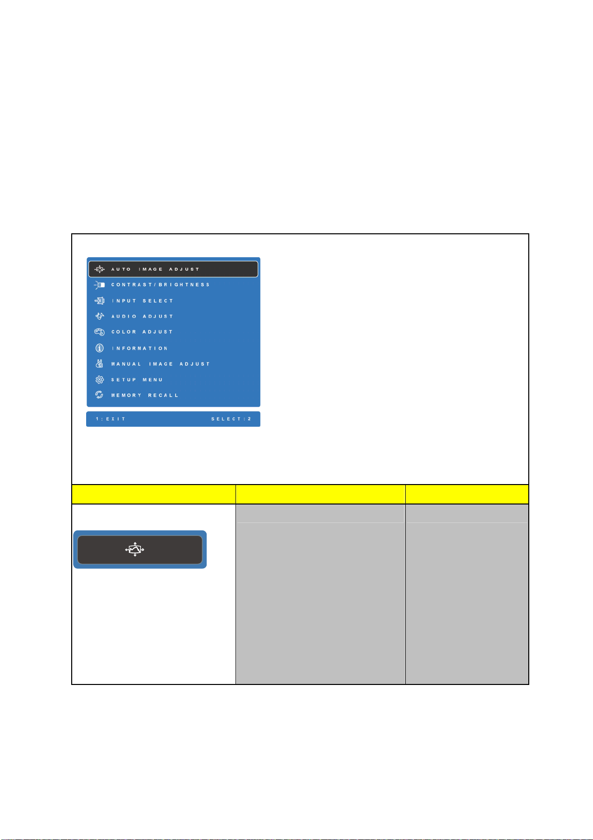
5.1.1 Main Menu OSD Table
Main Menu
Level 1 Level 2 Level 3
Auto Image Adjust
1. Key button definition:
[1]: OSD off
[2]: Execute the selected function
[Up]: Rolling up the slider
(When push the button on the top position,
the slider shall go down to the bottom item)
[Dn]: Rolling down the slider
(When push the button on the bottom
position, the slider shall go down to the top
item)
2. Under sRGB or DCR mode, the
Contrast/Brightness shall be disabled with
fate-out color. And it should not be selected.
1. Background = blanking
2. The message OSD position
is at the center.
3. After auto tune, OSD shall
be off
4. Only for analog mode
Page 22
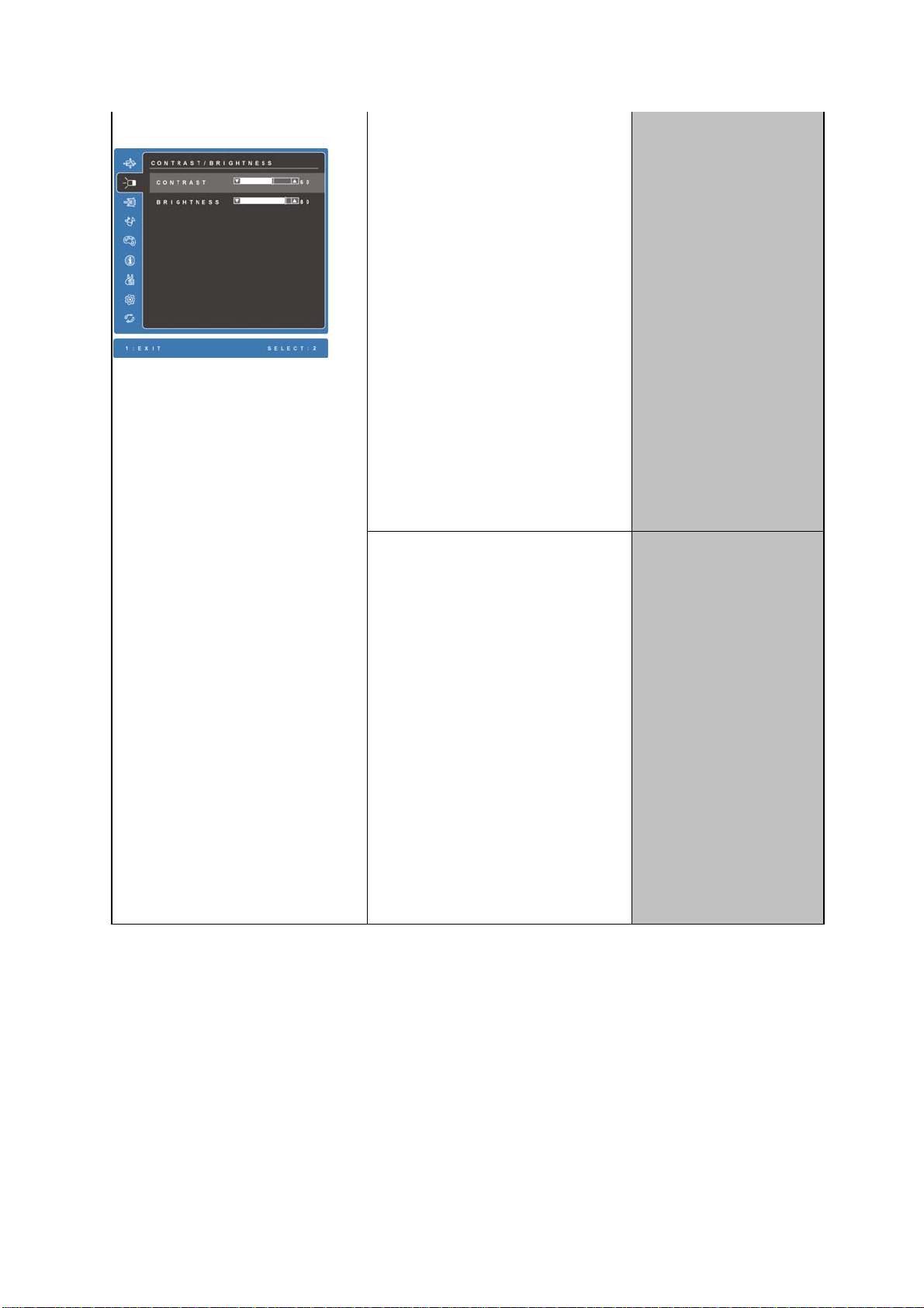
Contrast/Brightness
ViewSonic Corporation
VX2739wm-1
VX2739wm-CN
CONFIDENTIAL – DO NOT COPY
22
Contrast
1. Adjust range = 0 to 100
2. Default = 70
3. Key button definition:
[1] = Back to Main Menu or
OSD off
Key button definition:
[1]: Back to previous OSD
status
[2]: select to adjust value
setting.
[Up]: Move up the slider
[Dn]: Move down the slider
(depend on previous
status)
[Up] = Increase the OSD
value setting
[Dn] = Decrease the OSD
value
[Up]+[Dn]: Recall to default
Brightness
1. Adjust range = 0 to 100
2. Default = 100
3. Key button definition:
[1] = Back to Main Menu or
OSD off
(depend on previous
status)
[Up]: Increase the OSD value
setting
[Dn]: Decrease the OSD value
[Up]+[Dn]: Recall to default
Page 23
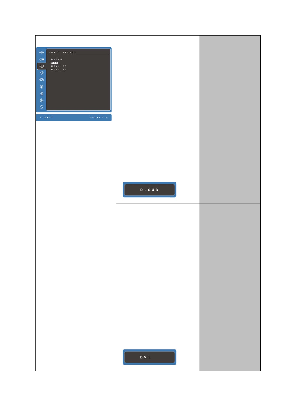
Input Select
ViewSonic Corporation
VX2739wm-1
VX2739wm-CN
CONFIDENTIAL – DO NOT COPY
23
D-SUB
Step 1: Turn off OSD.
Step 2:
1. Target video input port =
Analog
2. If signal detected from
target port, change to
target port.
3. If no signal detected from
1. Show on existing input port
by white-background color
2. Key button definition:
[1]: Back to previous OSD
status
[2]: Change to the selected
input port
[Up]: Move up the slider
[Dn]: Move down the slider
target port, keep existing
input port.
Step 3: Show on Input
Message OSD at the
right-top corner of screen for
1 second.
DVI
Step 1: Turn off OSD.
Step 2:
1. Target video input port =
Digital
2. If signal detected from
target port, change to
target port.
3. If no signal detected from
target port, keep existing
input port.
Step 3: Show on Input
Message OSD at the
right-top corner of screen for
1 second.
Page 24
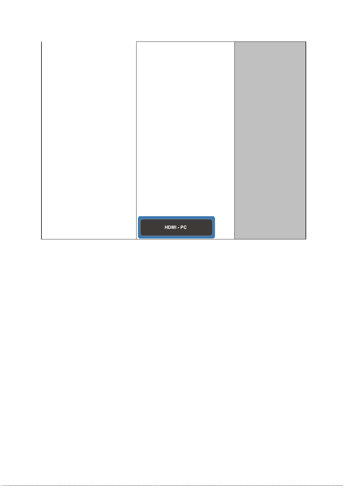
HDMI PC
ViewSonic Corporation
VX2739wm-1
VX2739wm-CN
CONFIDENTIAL – DO NOT COPY
24
Step 1: Turn off OSD.
Step 2:
1. Target video input port =
HDMI PC
2. If signal detected from
target port, change to
target port.
3. If no signal detected from
target port, keep existing
input port.
Step 3: Show on Input
Message OSD at the
right-top corner of screen for
1 second.
Page 25
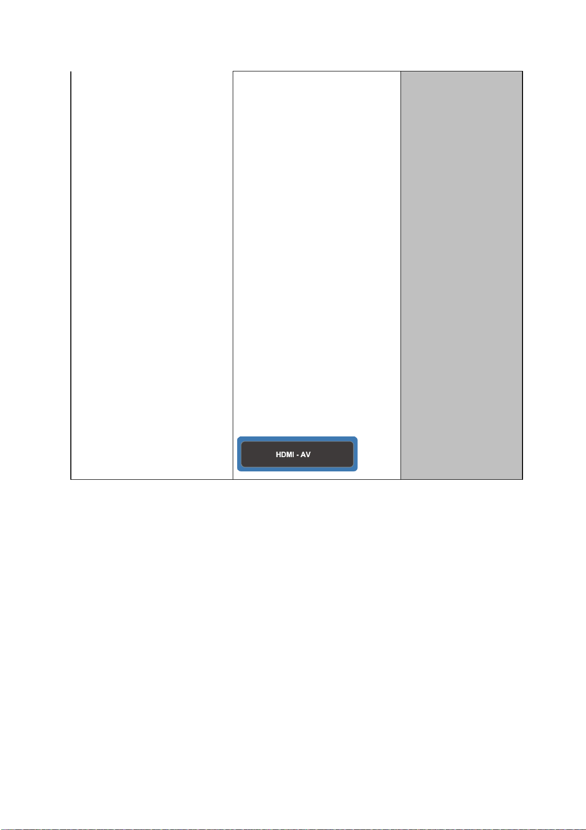
HDMI A V
ViewSonic Corporation
VX2739wm-1
VX2739wm-CN
CONFIDENTIAL – DO NOT COPY
25
Step 1: Turn off OSD.
Step 2:
1. Target video input port =
HDMI AV
2. If signal detected from
target port, change to
target port.
3. If no signal detected from
target port, keep existing
input port.
Step 3: Show on Input
Message OSD at the
right-top corner of screen for
1 second.
Note: HDMI input default
setting is HDMI AV, and
user can change to HDMI
PC and saved.
Page 26

Audio Adjust
ViewSonic Corporation
VX2739wm-1
VX2739wm-CN
CONFIDENTIAL – DO NOT COPY
26
1. The selected icon in Mute
Volume
will be highlighted
2. Key button definition:
[1]: Back to previous OSD
status
[2]: selected audio setting
[Up]: Move up the slider
[Dn]: Move down the slider
3. No signal, no output
1. Adjust range = 0 to 100
2. Default = 50
3. Key button definition:
[1]: Back to Audio Adjust OSD
[Up]: Increase the volume
setting
[Dn]: Decrease the volume
setting
Page 27

memorize its status after
ViewSonic Corporation
VX2739wm-1
VX2739wm-CN
CONFIDENTIAL – DO NOT COPY
27
DC/AC Off to On
Mute
1. Default = Off
; = On
= Off
2. Key button definition:
[1]: Back to Audio Adjust OSD
4. This function must
[2]: :Selected setting
3. When Mute function is
selected, any change in
Volume will disable to Mute.
Audio Input HDMI
Change audio source
to HDMI
Page 28

1. For HDMI mode only
ViewSonic Corporation
VX2739wm-1
VX2739wm-CN
CONFIDENTIAL – DO NOT COPY
28
(Under VGA/DVI mode, this is
disable).
2. Default = HDMI
3. Show on existing input port
by white-background color
4. Key button definition:
AUDIO IN
Change audio source
to jack plug (AUDIO
IN)
Color Adjust
[1] = Back to Main Menu
[2]: selected setting
sRGB
Change Color setting to sRGB
9300K
Change Color setting to 9300K
7500K
Change Color setting to 7500K
6500K
Change Color setting to 6500K
5000K
Change Color setting to 5000K
Page 29

ViewSonic Corporation
VX2739wm-1
VX2739wm-CN
CONFIDENTIAL – DO NOT COPY
29
User Color
Red
1. Show on existing input port
by white-background color
2. Default = 6500K
3. Key button definition:
[1]: Back to previous OSD
status
[2]: Change to the selected
color setting
[Up]: Move up the slider
[Dn]: Move down the slider
4. Under DCR mode (Dynamic
Contrast = On), sRGB shall
be disabled with fate-out
color. And it should not be
selected.
Change Color setting to user
color
1. Adjust range = 0 to
100
2. Default = 100
3. Key button
definition:
[1]: Back to Color
Adjust OSD
[2]: selected setting.
[Up]: Increase the
OSD value
setting
[Dn]: decrease the
OSD value
setting
Green
1. Adjust range = 0 to
100
2. Default = 100
3. Key button
definition:
[1]: Back to Color
Adjust OSD
[2]: selected setting.
[Up]: Increase the
OSD value
setting
[Dn]: decrease the
OSD value
setting
Page 30

Blue
ViewSonic Corporation
VX2739wm-1
VX2739wm-CN
CONFIDENTIAL – DO NOT COPY
30
1. Adjust range = 0 to
100
2. Default = 100
3. Key button
definition:
[1]: Back to Color
Adjust OSD
[2]: selected setting.
[Up]: Increase the
OSD value
setting
[Dn]: decrease the
OSD value
setting
Information
PC timing – Display
Resolution
Video timing – Display Video
Format
Page 31

ViewSonic Corporation
VX2739wm-1
VX2739wm-CN
CONFIDENTIAL – DO NOT COPY
31
Key button definition:
[1]: Back to Main Menu OSD
Manual Image
Adjust
1. Key button definition:
[1]: Back to previous OSD
status
[2]: Execute the selected
H./V. Position
Horizontal Position
1. Adjust range = 0 to
100
2. Key button
definition:
[1]: Back to Manual
Image Adjust
OSD
[2]: selected setting.
[Up]: Increase the
OSD value
setting
[Dn]: Decrease the
OSD value
Page 32

function
ViewSonic Corporation
VX2739wm-1
VX2739wm-CN
CONFIDENTIAL – DO NOT COPY
32
Vertical Position
[Up]: scroll up the slider
(When push the button on
the top position, the slider
shall go down to the
bottom item
[Dn]: Scroll down the slider
(When push the button on
the bottom position, the
slider shall go down to the
top item
2. Under Digital mode, all the
H./V. Position, Horizontal
Size and Fine Tune shall
be disabled with fate-out
color. And it should not be
selected.
3. Under native mode,
Horizontal Size
1. Adjust range = 0 to
100
2. Key button
definition:
[1]: Back to Manual
Image Adjust
OSD
[2]: selected setting.
[Up]: Increase the
OSD value
setting
[Dn]: Decrease the
OSD value
Sharpness shall be
disabled with fate-out
color. And it should not be
selected.
4. Under SRGB mode,
Dynamic Contrast shall be
disabled with fate-out
color. And it should not be
selected.
1. Adjust range = 0 to 100
2. Key button definition:
[1]: Back to Manual Image
Adjust OSD
[Up]: Increase the OSD
value setting
[Dn]: Decrease the OSD
value
Page 33

Fine Tune
ViewSonic Corporation
VX2739wm-1
VX2739wm-CN
CONFIDENTIAL – DO NOT COPY
33
1. Adjust range = 0 to 100
2. Key button definition:
[1]: Back to Manual Image
Adjust OSD
[Up]: Increase the OSD
value setting
[Dn]: Decrease the OSD
value
Page 34

Sharpness
ViewSonic Corporation
VX2739wm-1
VX2739wm-CN
CONFIDENTIAL – DO NOT COPY
34
1. Adjust range = {0 / 25 / 50 /
75 / 100}
2. Default = 50
3. Key button definition:
[1]: Back to Manual Image
Adjust OSD
[Up]: Increase the OSD
value setting
[Dn]: Decrease the OSD
value
Page 35

Dynamic Contrast
ViewSonic Corporation
VX2739wm-1
VX2739wm-CN
CONFIDENTIAL – DO NOT COPY
35
Swap on and off the Dynamic
Contrast function
Default = Off
; = On
= Off
When Dynamic Contrast is on,
below functions will be
disabled:
* Brightness/Contrast menu
* SRGB selection in Color
Adjust
* White balance hot key
* DDC/CI BR/CT adjustment
Response Time
Standard
Over Drive = off
Advanced
Over Drive = Level 1
( best quality with over
drive )
Page 36

1. Show on existing Response
ViewSonic Corporation
VX2739wm-1
VX2739wm-CN
CONFIDENTIAL – DO NOT COPY
36
Time setting by
white-background color
2. Key button definition:
[1]: Back to previous OSD
status
[2]: Change to the selected
Ultra Fast
Over Drive = Level 2
( faster than level 1 for
spec claim)
Response Time setting.
[Up]: Scroll up the slider
(When push the button on
the top position, the slider
shall go down to the
bottom item)
[Dn]: Scroll down the slider
(When push the button
on the bottom position, the
slider shall go up to the top
item)
3. Default = Standard
Aspect Ratio 4:3
Change aspect ratio to
4:3
Page 37

1. Show on existing Aspect
ViewSonic Corporation
VX2739wm-1
VX2739wm-CN
CONFIDENTIAL – DO NOT COPY
37
Ratio setting by
white-background color
2. Key button definition:
[1]: Back to previous OSD
status
[2]: Change to the selected
Full Screen
Fill screen with panel
native aspect ratio.
Display Mode setting.
[Up]: Scroll up the slider
(When push the button
on the top position, the
slider shall go down to the
bottom item)
[Dn]: Scroll down the slider
(When push the button
on the bottom position, the
slider shall go up to the top
item)
3. Default = full screen
Note : 1.When input signals
are wide format, this
function is disable.
2.When input signals are
non-wide format. this
function is enable.
Page 38

Display Mode
ViewSonic Corporation
VX2739wm-1
VX2739wm-CN
CONFIDENTIAL – DO NOT COPY
38
1. This function toggles RGB
and YUV display mode.
2. Show on existing Display
Mode setting by
white-background color
3. Key button definition:
RGB Mode
Set color space to
RGB mode for PC
timing mode
[1]: Back to previous OSD
status
[2]: Change to the selected
Display Mode setting.
[Up]: Scroll up the slider
(When push the button
on the top position, the
slider shall go down to the
bottom item)
[Dn]: Scroll down the slider
(When push the button
on the bottom position, the
slider shall go up to the top
item)
4. Save PC timing and DTV
timing setting separately.
5. Default = RGB Mode ( DVI
&VGA) ,
6. HDMI is auto detected by
Info Frame : ,
YPbPr -> YUV
Page 39

mode,
ViewSonic Corporation
VX2739wm-1
VX2739wm-CN
CONFIDENTIAL – DO NOT COPY
39
YUV Mode
Non-YPbPr -> RGB
mode.
7. It will recall to default after
Set color space to
YUV mode for HD
timing mode
AC/DC on/off or mode change.
ECO Mode
Standard
OSD adjust range = 0
to 100
1. This function toggles ECO
mode.
2. Show on existing ECO Mode
setting by white-background
color
3. Key button definition:
[1]: Back to previous OSD
status
[2]: Change to the selected
Display Mode setting.
[Up]: Scroll up the slider
(When push the button
on the top position, the
slider shall go down to the
bottom item)
[Dn]: Scroll down the slider
(When push the button
on the bottom position, the
slider shall go up to the top
Optimize
OSD adjust range = 0
to 100
Page 40

item)
ViewSonic Corporation
VX2739wm-1
VX2739wm-CN
CONFIDENTIAL – DO NOT COPY
40
4. Default = Standard
5. Under sRGB mode, ECO
Conserve
OSD adjust range = 0
to 100
Mode shall be disabled with
fate-out color. And it should
not be selected.
6. No matter DCR on or off,
lamp current will be changed
by ECO mode change.
7. While ECO or DCR setting
changed, the lamp current
shall be updated to new
setting immediately.
8. Do not lock Contrast or
Brightness OSD for ECO
function
9. Following is the lamp current
chart,
41
Page 41

Setup Menu
ViewSonic Corporation
VX2739wm-1
VX2739wm-CN
CONFIDENTIAL – DO NOT COPY
41
1. Key button definition:
[1]: Back to Main Menu
OSD
[2]: Execute the selected
function
[Up]: Scroll up the slider
(When push the button
on the top position, the
slider shall go down to
the bottom item)
[Dn]: Scroll down the slider
(When push the button
on the bottom position,
the slider shall go down
to the top item)
Language Select
1. Show on existing input port
by red color
2. Key button definition:
[1]: Back to previous OSD
status
[2]: Change to the selected
language setting
[Up]: Scroll up the slider
(When push the button on
the top position, the slider
shall go down to the
bottom item
[Dn]: Scroll down the slider
(When push the button on
the bottom position, the
slider shall go down to the
top item
English
Set OSD language to
English and keep in
Language Select OSD
French
Set OSD language to
French and keep in
Language Select OSD
German
Set OSD language to
German and keep in
Language Select OSD
Spanish
Set OSD language to
Spanish and keep in
Language Select OSD
Italian
Set OSD language to
Italian and keep in
Language Select OSD
Finnish
Set OSD language to
Finnish and keep in
Language Select OSD
Russian
Set OSD language to
Russian and keep in
Language Select OSD
Japanese
Set OSD language to
Japanese and keep in
Language Select OSD
Korean
Set OSD language to
Korean and keep in
Language Select OSD
Page 42

Traditional Chinese
ViewSonic Corporation
VX2739wm-1
VX2739wm-CN
CONFIDENTIAL – DO NOT COPY
42
Set OSD language to
Simplified Chinese
and keep in Language
Select OSD
Simplified Chinese
Set OSD language to
Traditional Chinese
and keep in Language
Select OSD
Resolution Notice
Swap on and off the Resolution
Notice function
Page 43

OSD Position
ViewSonic Corporation
VX2739wm-1
VX2739wm-CN
CONFIDENTIAL – DO NOT COPY
43
OSD H. Position
1. Adjust range = 0 to
100
2. Default = 50
3. Key button
definition:
[1]: Back to Setup
Menu OSD
[2]: selected
setting[Up]:
Increase the
OSD value
setting (move
OSD right)
[Dn]: Decrease the
OSD value
setting (move
OSD left)
[Up]+[Dn]: Recall to
default value
Page 44

OSD V. Position
ViewSonic Corporation
VX2739wm-1
VX2739wm-CN
CONFIDENTIAL – DO NOT COPY
44
1. Adjust range = 0 to
100
2. Default = 50
3. Key button
definition:
[1]: Back to Setup
Menu OSD
[2]: selected setting
[Up]: Increase the
OSD value
setting (move
OSD up)
[Dn]: Decrease the
OSD value
OSD Time Out
setting (move
OSD down)
[Up]+[Dn]: Recall to
default value
5
Set OSD Time Out to
5 Seconds
15
Set OSD Time Out to
15 Seconds
30
Set OSD Time Out to
30 Seconds
Page 45

ViewSonic Corporation
VX2739wm-1
VX2739wm-CN
CONFIDENTIAL – DO NOT COPY
45
1. Adjust range = 5, 15, 30, 60
2. Default = 15
3. Key button definition:
[1]: Back to Setup Menu
OSD
[Up]: Increase the OSD
60
Set OSD Time Out to
60 Seconds
value setting
[Dn]: Decrease the OSD
value setting
[Up]+[Dn]: Recall to default
value
OSD Background
Swap on and off the OSD
Background
; = Non-transparent
= Transparent
Page 46

Auto Power Off
ViewSonic Corporation
VX2739wm-1
VX2739wm-CN
CONFIDENTIAL – DO NOT COPY
46
Swap on and off the Auto
Power Off function
Power off the display
automatically when no signal is
detected for 3 minutes.
; = On
= Off
Note :
1. When no signal input with
Auto Power Off = ON, the
display will go into power
saving first. After 3 minutes, the
display will turn off
automatically.
2. When no signal input with
Auto Power Off = OFF, the
display will go into power
saving as normal display.
3. Default = Off
4. Memory Recall will call
back the setting to default.
5. When push Power Lock
hot key under Auto Power
Off = On, the message OSD
will show on for 3 seconds
(Power Lock function is
disabled),
6. The function will be
disabled when power button
locked.
Page 47

Sleep
ViewSonic Corporation
VX2739wm-1
VX2739wm-CN
CONFIDENTIAL – DO NOT COPY
47
30 Minutes
Set time before going
to Sleep mode = 30
Minutes
45 Minutes
Set time before going
to Sleep mode = 45
Minutes
60 Minutes
Set time before going
to Sleep mode = 60
1. Adjust time range before
going to sleep mode. Time
range = 30, 45, 60, 120
(Minutes) and Off.
2. Default = Off
3. When Sleep mode is
triggered, the power of
monitor will be turned off.
4. Only active in HDMI Mode
(both in AV&PC)
5. Key button definition:
[1]: Back to previous OSD
status
[2]: Change to the selected
sleep time setting
[Up]: Rolling up the slider
(When push the button
Minutes
120 Minutes
Set time before going
to Sleep mode = 120
Minutes
Off
Disable Sleep mode.
Memory Recall
on the top position, the
slider shall go down to
the bottom item
[Dn]: Rolling down the slider
(When push the button
on the bottom position,
the slider shall go down
to the top item
Page 48

ViewSonic Corporation
VX2739wm-1
VX2739wm-CN
CONFIDENTIAL – DO NOT COPY
48
1. Background = blanking
2. Recall white balance to
factory setting
3. Recall all the OSD setting to
the default. (include the
R/G/B in User Color)
4. Show the message OSD
position is at the center for
3 seconds.
5. Clean FIFO timing mode
buffer
6. Execute Auto Image Adjust
Note: Memory Recall should
not effect on Language, Power
Lock Settings or Input
Priority
Page 49

ViewSonic Corporation
VX2739wm-1
VX2739wm-CN
CONFIDENTIAL – DO NOT COPY
49
5.1.2 OSD Lock short cuts function for the buttons
The OSD lock will be activated by pressing the front panel control buttons [1] +
[▲] for 10 seconds *1. If the user then tries to access the OSD by pressing any
of the buttons, a message will appear on the screen for 3 seconds showing
"OSD Locked" *2. The OSD lock will be deactivated by pressing the front panel
control buttons [1] + [▲] again for 10 seconds*3.
*1 The OSD Lock message as below,
Range = 0 to 10
*2 The OSD Locked message as below,
*3 The OSD Unlock message as below,
Range = 0 to 10
*4 When the OSD is locked will lock all functions, including “Volume”, “Mute”
and others.
*5 Status bar indicating OSD Lock or Unlock is in progress and when complete
will indicate “OSD Locked” or “OSD Unlocked” for 3 seconds as below,
OSD Locked
OSD Unlocked
Page 50

ViewSonic Corporation
VX2739wm-1
VX2739wm-CN
CONFIDENTIAL – DO NOT COPY
50
*6 When OSD appears on screen, the OSD Lock/Unlock short cut key will be
disabled.
5.1.3 Power Lock short cuts function for the buttons
The Power lock will be activated by pressing the front panel control buttons [1] +
[▼] for 10 seconds *1. Locking the power button means that the user won't be able
to turn off the LCD while the power button is locked. If the user presses the power
button while it is locked, a message will appear on the screen for 3 seconds
*2
showing "Power Button Locked"
. It also means that with the power button
locked, the LCD would automatically turn back "On" when power is restored after
a power failure. If the power button is not in the locked mode, then power should
return to it's previous state when power is restored after a power failure. The
Power lock will be deactivated by pressing the front panel control buttons [1] + [▼]
again for 10 seconds
*3
.
*1 The Locking Power Button message as below,
Range = 0 to 10
*2 The Power Button Locked message as below,
*3 The Unlocking Power Button message as below,
Range = 0 to 10
*4 Status bar indicating Power Button Lock or Unlock is in progress and when
complete it will indicate “Power Button Locked” or “Button Unlocked” for 3
seconds as below,
Power Button Locked
Page 51

ViewSonic Corporation
VX2739wm-1
VX2739wm-CN
CONFIDENTIAL – DO NOT COPY
51
Button Unlocked
*5 When OSD appears on screen, the OSD Lock/Unlock short cut key will be
disabled.
5.1.4 Input Signal Notice Actions
1. The Input Signal Notice OSD appears 1 second when power turns on or
change input signal.
2. The Input Signal Notice OSD position is on the right-top side of image.
3. The OSD message as below,
5.1.5 Resolution Notice Actions
1. Resolution Notice OSD should show on screen after changing to non-native
mode for 30 sec.
Page 52

ViewSonic Corporation
VX2739wm-1
VX2739wm-CN
CONFIDENTIAL – DO NOT COPY
52
2. Key button definition:
[1]: Turn off the OSD message.
[2]: Turn off the OSD message and disable Resolution Notice function
3. The OSD should disappear after 10 sec or by pushing button [1] or [2]
4. After the OSD turns off, it will not show on again before next timing change,
input change or power off.
5. Resolution Notice function should be disabled when push button [2] under
Resolution Notice OSD
6. The “1920x1080” will be replaced by actual panel resolution.
5.1.6 0-Touch™ Function Actions
1. Execute Auto Image Adjust when new mode detected, and save the settings to
buffer for further use
2. It should be reset by Memory Recall function
(Should not reset by power off, power unplug and others)
5.1.7 OSD Auto Save
The OSD shall save new settings when it is turned off by the user or when it times
out. There shall not be a separate save
5.1.8 Out of range
While non-defined timing is detected, following OSD message will keeps showing
on,
Page 53

ViewSonic Corporation
VX2739wm-1
VX2739wm-CN
CONFIDENTIAL – DO NOT COPY
53
1. If the timing is over spec (Fh, Fv or dot clock), the image shall be blanking, and
OSD background shall be non-transparent.
2. If the timing is inspect but not defined, the image shall be non-blanking.
5.1.9 No signal
While no signal is detected, the following OSD message shall shows on 3
seconds then go in to power saving.
OSD Background = Non-transparent
Image = Blanking
Page 54

5.2 BIOS /Firmware Update SOP
ViewSonic Corporation
VX2739wm-1
VX2739wm-CN
CONFIDENTIAL – DO NOT COPY
54
Step1: Prepare a PC and the target HDTV.
Step 2: Connect isp board by usb cable (from PC to isp board) and D-sub cable
(from isp board to monitor).
Step 3: Copy the .bin format file (for example, VX2739WM_252.bin) to a folder of
the computer from the CD.
Step 4: Double click the ISP Tool with the CD as the following icon to open the ISP
tool.
Step 5: The outline of isp tool.
Step 6: Click on the “Connect” icon. A pop menu will show up. Press the “OK”
button.
Page 55

ViewSonic Corporation
VX2739wm-1
VX2739wm-CN
CONFIDENTIAL – DO NOT COPY
55
Step 7: Click on the “Read” icon. Press the “Read” button and select the .bin file
which is copied to the folder of the computer. Press the “open” button.
Page 56

ViewSonic Corporation
VX2739wm-1
VX2739wm-CN
CONFIDENTIAL – DO NOT COPY
56
Step 8: Click on the “Auto” icon and press the “Run” button.
Step 9: Flash is running.
Page 57

ViewSonic Corporation
VX2739wm-1
VX2739wm-CN
CONFIDENTIAL – DO NOT COPY
57
Step 10: Flash is finished.
5.3 Disassembly Procedure
Please follow the information provided in this section to perform the complete
disassembly procedure of the LCD panel. Be sure to use proper tools described
below.
LCD consists of various Parts. This chapter describes the procedures for the
complete parts disassembly. In addition, in between procedures, the detailed
disassembly procedure of individual parts will be provided for your service needs.
The disassembly procedure consists of the following steps:
1. Base Cover
2. LED Board
3. Front Cover
4. Keypad
5. PSU Board
6. Main Board
Page 58

7. Speakers
ViewSonic Corporation
VX2739wm-1
VX2739wm-CN
CONFIDENTIAL – DO NOT COPY
58
Base & Cover
1. Remove 4 screws (M4*13L (X)) that fixing on the neck.
2. Push down the Base and remove it.
Page 59

ViewSonic Corporation
VX2739wm-1
VX2739wm-CN
CONFIDENTIAL – DO NOT COPY
59
3. Remove the 1 screw to unplug the stand neck.
4. Remove the 4 screws to take off the Hinge.
Page 60

5. Then remove the screws.
ViewSonic Corporation
VX2739wm-1
VX2739wm-CN
CONFIDENTIAL – DO NOT COPY
60
6. Take off the Rear Cover carefully.
Page 61

LED Board
ViewSonic Corporation
VX2739wm-1
VX2739wm-CN
CONFIDENTIAL – DO NOT COPY
61
1. Take off the 4 tapes on the LVDS wire and Keypad wire.
2. Unplug the power wire and keypad wire.
3. Remove the 2 screws on the LED board.
Page 62

4. Unplug the LED board wire and take off the LED board.
ViewSonic Corporation
VX2739wm-1
VX2739wm-CN
CONFIDENTIAL – DO NOT COPY
62
Front Cover
1. Take off the Shielding from the Panel.
2. Take off the Front Cover from the Panel.
Page 63

Keypad
ViewSonic Corporation
VX2739wm-1
VX2739wm-CN
CONFIDENTIAL – DO NOT COPY
63
Take off the Keypad from the Front Cover.
PSU Board
1. Remove 4 screws on the Shielding.
Page 64

ViewSonic Corporation
VX2739wm-1
VX2739wm-CN
CONFIDENTIAL – DO NOT COPY
64
2. Unplug the power cable from the PSU board.
3. Remove the 4 screws and take off the PSU board.
Page 65

MainBoard
ViewSonic Corporation
VX2739wm-1
VX2739wm-CN
CONFIDENTIAL – DO NOT COPY
65
1. Remove 4 screws that fixing on the MainBoard.
3. Disconnect the LVDS and Keypad Cable from MainBoard and remove the
MainBoard.
Page 66

Speaker
ViewSonic Corporation
VX2739wm-1
VX2739wm-CN
CONFIDENTIAL – DO NOT COPY
66
1. Remove the 4 screws of the Speaker.
2. Disconnect the Speaker cable on the shielding and remove the Speakers.
Page 67

ViewSonic Corporation
VX2739wm-1
VX2739wm-CN
CONFIDENTIAL – DO NOT COPY
67
6. Troubleshooting Flow Chart
Can not boot
Can not boot
Check AC-power
whether is OK
OK
Disassembles the system
NG
Replacement the
AC Power
Supply
Equipment
to remove the PSU, and
supplies the power directly
OK
The nondefective
Replace the PSU
and Test
NG
Replacement MB and
Abnormal screen
1.Test after boot,the screen left bottom has the streaks
2. Purple screen after booting
3. White screen appears after booting
Page 68

4. White-black screen after booting
ViewSonic Corporation
VX2739wm-1
VX2739wm-CN
CONFIDENTIAL – DO NOT COPY
68
5. Black screen after booting
Abnormal screen
Double check
abnormal system
Disassembles LCD
cover &check LVDS
cable at its place
Assembly
machine to test
FAIL
Test LVDS cable
PASS
NG
Rearrange LVDS
cable & assembly
machine to test
PASS
PASS
FAIL
Replace PSU
&test
PASS
FAIL
Replace MB
The nondefective
&test
PASS
FAIL
Replace
PANE L &test
PASS
Page 69

ViewSonic Corporation
VX2739wm-1
VX2739wm-CN
CONFIDENTIAL – DO NOT COPY
69
Abnormal sound
1. No sound
2. Abnormal sound;
3. TV mode with noise.
4. Intermittent sound
Page 70

Abnormal sound
p
ViewSonic Corporation
VX2739wm-1
VX2739wm-CN
CONFIDENTIAL – DO NOT COPY
70
Reset abnormal
machine
Disassembles LCD
cover &check speaker
cable
Reassembly
machine to test
FAIL
Replace Speaker
PASS
NG
PASS
PASS
cable and test
FAIL
PASS
The nondefective
PASS
FAIL
Replace
S
eaker&test
Replace MB
&test
Page 71

ViewSonic Corporation
VX2739wm-1
VX2739wm-CN
CONFIDENTIAL – DO NOT COPY
71
Keypad Board does not work
OSD is unstable or not working
Y
Is Key Pad Board
connecting normally?
Y
Is Button Switch
normally?
Y
N
Connect Key Pad Board
N
Replace Button Switch
Is Key Pad Board
Normally?
Y
Check Main Board
N
Replace Key Pad Board
Page 72

After boot power light does not bright
ViewSonic Corporation
VX2739wm-1
VX2739wm-CN
CONFIDENTIAL – DO NOT COPY
72
After boot power
light does not bright
Reset the abnormal
machine
FAIL
Disassemble the
LCD cover and
check the IR cable
NG
PASS
Replace new IR
PASS
The nondefective
cable and test
FAIL
PASS
Replace IR
board and test
FAIL
PASS
Replace MB
and test
Page 73

7. Block Diagrams
ViewSonic Corporation
VX2739wm-1
VX2739wm-CN
CONFIDENTIAL – DO NOT COPY
73
Page 74

8. Schematic Diagrams
ViewSonic Corporation
VX2739wm-1
VX2739wm-CN
CONFIDENTIAL – DO NOT COPY
74
Page 75

ViewSonic Corporation
VX2739wm-1
VX2739wm-CN
CONFIDENTIAL – DO NOT COPY
75
Page 76

ViewSonic Corporation
VX2739wm-1
VX2739wm-CN
CONFIDENTIAL – DO NOT COPY
76
Page 77

9. PCB Layout Diagrams
ViewSonic Corporation
VX2739wm-1
VX2739wm-CN
CONFIDENTIAL – DO NOT COPY
77
Page 78

10. Exploded Diagram and Exploded Parts List
ViewSonic Corporation
VX2739wm-1
VX2739wm-CN
CONFIDENTIAL – DO NOT COPY
78
Page 79

N
N
N
N
N
(B)
N
(F)
(X)
(X)
(W)
(X)
N
N
N
N
N
A
N
N
N
N
EXPLODED PARTS LIST (VX2739wm-1/VX2739wm-CN)
ViewSonic Corporation
VX2739wm-1
VX2739wm-CN
CONFIDENTIAL – DO NOT COPY
79
ViewSonic Model Number: VS12843
Rev: 1a
Item ViewSonic P/N Ref. P/N Description Q'ty
A
1
A
2
A
3
HW-00009268
4
HW-00009267
5
PL-00008859
6
A
7
C-00010201
8
A
9
M-00008598
10
HW-00009272
11
A
12
HW-00009269
13
HW-00009270
14
HW-00009271
15
HW-00009275
16
HW-00009273
17
A
18
A
19
A
20
PL-00008860
21
C-00010202
22
CB-00009417
23
A
24
A
25
A
26
A
27
A
28
A
29
13EB-1CQ0201 EB1C VX2739 FRONT COVER 1
13EB-1CQ0501 EB1C VX2739 POWER KEY DECOR 1
13EB-1CQ0301 EB1C VX2739 POWER KEY 1
13EB-1CB0301 EB1C VX2739 SHIELDING ASSY 1
13EB-1CN0101 EB1C VX2739 HINGE 1
13EB-1CQ0101 EB1C VX2739 FUNCTION KEY 1
13EB-1CQ0601 EB1C VX2739 STAND NECK 7
13EB-1CB0201 EB1C VX2739 REAR COVER ASSY 4
13EB-1CQ0401 EB1C VX2739 STAND BASE 4
13EB-03U0301 B05 RUBBER FOOT D=20.6 10
131C-000R000 SCREW M4*10
131A-004U000 SCREW M4*8L
131A-007U000 SCREW M3*6.0
131A-00JG000 SCREW M3*4+6L
131A-007G000 SCREW M4*6L
1302-00EW000 STAND OFF #4-40*7+5 W-NI 1
131C-006C000 SCREW M3*8L
13EB-1BU0101 EB1B VX2439 HAND SCREW M4-13L 1
13EB-1BQ0801 EB1B VX2739 STAND RING 1
13EB-1CN0301 EB1C/VX2739/LOGO PLATE 1
13EB-1CB0401 EB1C/VX2739/STAND NECK ASSY 1
13EB-1CB0501 EB1C/VX2739/STAND BASE ASSY 1
1414-03LN000 W.H CABLE 10P TO 10P,L:200mm 1
1414-03KT000 W.H CABLE 8P TO 4P TO 4P A 1
1412-00VH000 FFC CABLE 30P,P:1.0mm,L:220mm
04A4-00JE000 SPEAKER 2W 300/600MM VX2739 A 1
1414-03KR000 W.H CABLE 5P TO 5P,L:800mm A 1
1414-03KS000 W.H CABLE 4P TO 4P,L:850mm A 2
1414-03L8000 W.H CABLE 2P TO 2P,L:120mm A 1
B-ZN #2 4
B-ZN #2 1
W-NI #2 4
W-NI #2 4
W-NI 1
W-NI 1
1
Page 80

16
Item ViewSonic P/N Ref. P/N Description Q'ty
1 P-00010256
1505-016Q000 EPS CUSHION VX2739WM (TL) 1
2 P-00010257
1505-016P000 EPS CUSHION VX2739WM (TR) 1
3 P-00010258
1505-016S000 EPS CUSHION VX2739WM (BL) 1
4 P-00010259
1505-016R000 EPS CUSHION VX2739WM (BR) 1
5 NA
1516-00VM000 PE BAG STAND VX2739WM
10 NA
1522-01M0000 FLYER SERVICE ML VX2439WM R1.0 1
11 NA
1522-01M4000 BASE INSTALLATION ENG VX2439WM 1
13 NA
1516-00VN000 PET COVER VX2739WM 1
16 NA
1517-000Q000 ZIP BAG FOR VIEWSONIC 1
17 NA
1506-0C1Q000 INSTALATION QUIDE ENG VX2439WM 1
18 DC-00010334
1509-02GW000 CD ML VX2739WM 1
21 CB-00009408
1417-003E000 AUDIO CBL 3.5 STEREO PLUG BOTH 1
22 A-00008737
1411-00EX000 AC POWER CORD UL/CSA/3P/3C 1
23 CB-00009409
1401-00DB000 VGA CABLE HDB(M) TO HDB(M) 15P 1
24 CB-00009410
1401-00DE000 DVI(M) TO DVI(M) 18+1P L:1.8M 1
25 CB-00009411
1401-00DC000 USB CABLE A/M TO B/M L:1.8M 1
26 P-00010261
1524-02KH000 PAPER CUSHION VX2739 1
27 DC-00010333
1506-0CYT000 QSG ML VX2739WM VSI/VSE/VSA 1
29 P-00010255
1503-02G8000 CARTON VX2739WM 1
30 NA
1516-011B000 EPE BAG VX2739WM 1
31 P-00010260
1524-02FT000 CABLE CUSHION VX2439WM 1
PACKING PART LIST (VX2439wm-1/VX2439wm-CN)
ViewSonic Model Number: VS12841
Rev: 1a
ViewSonic Corporation
VX2739wm-1
VX2739wm-CN
CONFIDENTIAL – DO NOT COPY
80
2
8
12
10
7
1
6
11
13
18
9
5
17
4
14
15
21
3
19
OR PLAYPENS. THIS BAG IS NOT A TOY.
DO NOT USE IN CRIBS, BEDS, CARRIAGES,
KEEP AWAY FROM BABIES AND CHILDREN.
TO AVOID DANGER OF SUFFOCATION.
H
2
20
Page 81

11. Recommended Spare Parts List
Rev: 1a
Serial No. Prefix: RKD (VX2739wm-1) / RRG (VX2739wm-CN)
Item Category Part Name Description ECR/ECN ViewSonic P/N Ref. P/N Ref. NO Compatibility Location Universal number# Remark
1 Power Cord AC POWER CORD UL/CSA/3P/3C
A-00008737
1411-00EX000 Main Source
2 Audio Cable AUDIO CBL 3.5 STEREO PLUG BOTH
CB-00009408
1417-003E000 Main Source
3 Signal Cable VGA CABLE HDB(M) TO HDB(M) 15P
CB-00009409
1401-00DB000 Main Source
4 Signal Cable DVI(M) TO DVI(M) 18+1P L:1.8M
CB-00009410
1401-00DE000 Main Source
5 USB Cable USB CABLE A/M TO B/M L:1.8M
CB-00009411
1401-00DC000 Main Source
6 Main Board VX2739WM/MAIN BD./VIEWSONIC
B-00010281
69EB3HM10A01P Main Source
7 Power Board POWER SUPPLY 68W(LIPS)
B-00010282
04A5-009F000 Main Source
8 Key Pad
VX2439WM/KEYPAD BD./VIEWSONIC
B-00010283
69EB3GK10A01P Main Source
9 USB Board VX2739WM/USB BD/VIEWSONIC
B-00010284
69EB3HJ10A01P Main Source
10 LED Board VX2439WM/LED BD./VIEWSONIC
B-00010285
69EB3GE10A01P Main Source
11 IO Board VX2739WM/EU/IO BD./VIEWSONIC
B-00010286
69EB3HB10A01P Main Source
12 Front Bezel EB1C/VX2739/FRONT COVER ASSY
C-00010200
13EB-1CB0101 Main Source
13 Back Cover EB1C/VX2739/REAR COVER ASSY
C-00010201
13EB-1CB0201 Main Source
14 Base Assembly EB1C/VX2739/STAND BASE ASSY
C-00010202
13EB-1CB0501 Main Source
15 Flat Cable FFC CABLE 30P,P:1.0mm,L:195mm
CB-00009412
1412-00VH000 Main Source
16 Cable W.H CABLE 8P TO 4P TO 4P
CB-00009413
1414-03KT000 Main Source
17 Cable W.H CABLE 5P TO 5P,L:800mm
CB-00009414
1414-03KR000 Main Source
18 Cable W.H CABLE 4P TO 4P,L:770mm
CB-00009415
1414-03KS000 Main Source
19 Cable W.H CABLE 2P TO 2P,L:100mm
CB-00009416
1414-03L8000 Main Source
20 Cable W.H CABLE 10P TO 10P,L:180mm
CB-00009417
1414-03LN000 Main Source
21 Qucik Start Guide (QSG) QSG ML VX2739WM VSI/VSE/VSA
DC-00010333
1506-0CYT000 Main Source
22 User's Guide (CD ROM) CD ML VX2739WM
DC-00010334
1509-02GW000 Main Source
23 Label / Sticker UPC LABEL VX2739WM R1.0
DC-00010335
1510-0E9P000 Main Source
24 Label / Sticker SERIAL LABEL VIEWSONIC
DC-00010336
1510-0E9N000 Main Source
25 Label / Sticker RATING LABEL VX2739WM
DC-00010337
1510-0GYM000 Main Source
26 Label / Sticker POP STICKER VX2739WM
DC-00010338
1510-0EPM000 Main Source
27 Panel LCD TFT 27.0' FULL HD
E-00010096
1823-00SL000 Main Source
28 Speaker SPEAKER 2W 300/600MM VX2739
E-00010097
04A4-00JE000 Main Source
29 Hinge EB1C VX2739 HINGE
HW-00009267
13EB-1CN0101 Main Source
30 Shielding Cover EB1C/VX2739/SHIELDING ASSY
HW-00009268
13EB-1CB0301 Main Source
31 Screw SCREW M3*6.0 (X) W-NI #2
HW-00009269
131A-007U000 Main Source
32 Screw SCREW M3*4+6L (X) W-NI #2
HW-00009270
131A-00JG000 Main Source
33 Screw SCREW M4*6L (W) W-NI
HW-00009271
131A-007G000 Main Source
34 Screw SCREW M4*10(B) B-ZN #2
HW-00009272
131C-000R000 Main Source
35 Screw SCREW M3*8L (X) W-NI
HW-00009273
131C-006C000 Main Source
36 Screw EB1C SCREW M4*10L (F) B-ZN #2
HW-00009274
13EB-1CU0101 Main Source
37 Screw STAND OFF #4-40*7+5 W-NI
HW-00009275
1302-00EW000 Main Source
38
Miscellaneous: [Switch,
Rubber Foot B05 RUBBER FOOT D=20.6 M-00008598 13EB-03U0301 Main Source
39 Carton CARTON VX2739WM P-00010255 1503-02G8000 Main Source
40 Cushion EPS CUSHION VX2739WM (TL) P-00010256 1505-016Q000 Main Source
41 Cushion EPS CUSHION VX2739WM (TR) P-00010257 1505-016P000 Main Source
42 Cushion EPS CUSHION VX2739WM (BL) P-00010258 1505-016S000 Main Source
43 Cushion EPS CUSHION VX2739WM (BR) P-00010259 1505-016R000 Main Source
44 Cushion CABLE CUSHION VX2439WM P-00010260 1524-02FT000 Main Source
45 Cushion PAPER CUSHION VX2739 P-00010261 1524-02KH000 Main Source
46 Cushion PAPER CUSHION VG2739WM P-00010262 1524-02DS000 Main Source
47 Button EB1C VX2739 FUNCTION KEY
PL-00008859
13EB-1CQ0101 Main Source
48 Pedestal EB1C/VX2739/STAND NECK ASSY
PL-00008860
13EB-1CB0401 Main Source
Remark 1:
Remark 2:
Notice:
5. Parts relationship (Main/Second source or 1/2/3/4) should be added in the "Compatibility" column
Plastics: [Pedestal,
stand/neck, Plate,
[LCD Panel, Speaker,
6. If any part for certain product isn't listed in the form, supplier/PE can add it themselves and keep the part name unified.
All revised RSPLs with newly added items or any change made should be highlighted and correlated with the ECN/ECR approved by ViewSonic Corporation. This is to eliminate repeated
1. For some special parts, some photos for identification purpose may be asked by request
3. All internal cables/wires should be put in the "Cables" category
4. All external cables should be put in the "Accessories" category
Assembly]
RECOMMENDED SPARE PARTS LIST (VX2739wm-1/VX2739wm-CN)
PC Board Assembly:
ViewSonic Corporation
VX2739wm-1
VX2739wm-CN
CONFIDENTIAL – DO NOT COPY
81
ViewSonic Model Number: VS12843
Accessories: [Adapter,
Battery, Remote
Controller, Power Cord,
External Cables, Mouse,
[All boards or PCBA]
Cabinets: [Front Bezel,
All Covers, Base/Stand
Cables: [All internal
Cables/wires]
Documentation: [Quick
Start Guide, CD Rom,
Label/Sticker]
Electronic Components:
Hardware: [Screw,
Bracket, Hinge]
Packing Material:
[Carton, Box, Foam,
Bags]
Above listed items are examples, supplier can expand the rows to add more necessary items.
2. For all internal cables, there must be some wordings on the "Description" column about where the cable is used (connecting to which two parts)
Page 82

N
N
N
N
N
N
N
N
N
N
(
)
N
N
N
N
N
N
N
N
N
N
N
N
N
N
(X)
(X)
(W)
(B)
I
N
(X)
N
N
(F)
N
N
N
N
N
N
(TL)
(TR)
(BL)
N
BOM LIST (VX2739wm-1/VX2739wm-CN)
ViewSonic Corporation
VX2739wm-1
VX2739wm-CN
CONFIDENTIAL – DO NOT COPY
82
ViewSonic Model Number: VS12843
Rev: 1a
Item ViewSonic P/N Ref. P/N Description Location Universal number# Q'ty Unit
1
2
3
4
5
6
7
8
9
10
11
12
13
14
15 C-00010200
16
17
18
19
20 C-00010201
21
22
23 PL-00008859
24 HW-00009268
25
26
27 HW-00009267
28 PL-00008860
29
30
31 HW-00009269
32 HW-00009270
33 HW-00009271
34 HW-00009272
35 HW-00009275
36
37 HW-00009273
38 C-00010202
39
40 M-00008598
41
42 HW-00009274
43
44
45
46
47
48
49 P-00010256
50 P-00010257
51 P-00010258
52
53 DC-00010335
A
A
A
A
A
A
A
A
A
A
A
A
A
A
A
A
A
A
A
A
A
A
A
A
A
A
A
A
A
A
A
A
A
A
69EB3GE10A01P VX2439WM/LED BD./VIEWSONIC 1
69EB3HB10A01P VX2739WM/EU/IO BD./VIEWSONIC 1
69EB3HM10A01P VX2739WM/MAIN BD./VIEWSONIC 1
69EB3HJ10A01P VX2739WM/USB BD/VIEWSONIC 1
69EB3GK10A01P VX2439WM/KEYPAD BD./VIEWSONIC 1
1414-03KT000 W.H CABLE 8P TO 4P TO 4P 1
1414-03KR000 W.H CABLE 5P TO 5P,L:800mm 1
1414-03KS000 W.H CABLE 4P TO 4P,L:770mm 2
1414-03L8000 W.H CABLE 2P TO 2P,L:100mm 1
04A5-009F000 POWER SUPPLY 68W
1414-03LN000 W.H CABLE 10P TO 10P,L:180mm 1
1412-00VH000 FFC CABLE 30P,P:1.0mm,L:195mm 1
04A4-00JE000 SPEAKER 2W 300/600MM VX2739 1
1823-00SL000 LCD TFT 27.0' FULL HD 1
13EB-1CB0101 EB1C/VX2739/FRONT COVER ASSY 1
13EB-1CQ0201 EB1C VX2739 FRONT COVER 1
13EB-1CN0301 EB1C/VX2739/LOGO PLATE 1
13EB-1CQ0501 EB1C VX2739 POWER KEY DECOR 1
13EB-1CQ0301 EB1C VX2739 POWER KEY 1
13EB-1CB0201 EB1C/VX2739/REAR COVER ASSY 1
13EB-1CQ0701 EB1C VX2739 REAR COVER 1
13EB-1BN0201 EB1B VX2439 KENSINGTON LOCK 1
13EB-1CQ0101 EB1C VX2739 FUNCTION KEY 1
13EB-1CB0301 EB1C/VX2739/SHIELDING ASSY 1
13EB-1CN0401 EB1C VX2739 SHIELDING 1
13EB-1CN0201 EB1C/VX2739/HINGE BKT 1
13EB-1CN0101 EB1C VX2739 HINGE 1
13EB-1CB0401 EB1C/VX2739/STAND NECK ASSY 1
13EB-1CQ0601 EB1C VX2739 STAND NECK 1
13EB-1CQ0801 EB1C VX2739 NECK RING 1
131A-007U000 SCREW M3*6.0
131A-00JG000 SCREW M3*4+6L
131A-007G000 SCREW M4*6L
131C-000R000 SCREW M4*10
1302-00EW000 STAND OFF #4-40*7+5 W-N
13EB-0DU0A01 TAPE 8
131C-006C000 SCREW M3*8L
13EB-1CB0501 EB1C/VX2739/STAND BASE ASSY 1
13EB-1CQ0401 EB1C VX2739 STAND BASE 1
13EB-03U0301 B05 RUBBER FOOT D=20.6 7
13EB-1BU0101 EB1B VX2439 HAND SCREW M4-13L 1
13EB-1CU0101 EB1C SCREW M4*10L
13EB-0LU0301 EB0L GASKET W10*H2*L44 1
13EB-09U0E01 EB09 EU AL TPAE 30x60MM 2
13EB-09U0101 EB09 TAPE30*30MM/HANNSATR 25 5
13EB-13N0401 EB13 32 GROUNDING SPRING 28MM 1
13N0-00U0I01 A2K-7J GASKET TAPE FOR VGA BRK 2
13EB-1CU0201 EB1C VX2739GASKT L175*W12*H1.0 4
1505-016Q000 EPS CUSHION VX2739WM
1505-016P000 EPS CUSHION VX2739WM
1505-016S000 EPS CUSHION VX2739WM
1516-00VM000 PE BAG STAND VX2739WM 1
1510-0E9P000 UPC LABEL VX2739WM R1.0 1
LIPS
W-NI #2 10
W-NI #2 4
W-NI 1
B-ZN #2 4
W-NI 4
B-ZN #2 4
1
4
1
1
1
Page 83

Item ViewSonic P/N Ref. P/N Description Location Universal number# Q'ty Unit
N
N
N
N
N
N
(BR)
N
N
G
N
N
(M)
(M)
N
ViewSonic Corporation
VX2739wm-1
VX2739wm-CN
CONFIDENTIAL – DO NOT COPY
83
54 DC-00010336
55
56 DC-00010338
57
58
59
60
61
62 P-00010262
63 P-00010259
64
65
66 DC-00010334
67
68
69 CB-00009408
70 A-00008737
71 CB-00009409
72 CB-00009410
73 CB-00009411
74 P-00010261
75 DC-00010333
76 DC-00010337
77 P-00010255
78
79 P-00010260
A
A
A
A
A
A
A
A
A
A
A
1510-0E9N000 SERIAL LABEL VIEWSONIC 1
1510-0E9K000 HI-POT PASS LABEL VX2439WM 1
1510-0EPM000 POP STICKER VX2739WM 1
1537-0016000 PALLET /US 1
1522-01M0000 FLYER SERVICE ML VX2439WM R1.0 1
1522-01M4000 BASE INSTALLATION ENG 1
1524-00L9000 LAYER PAD FOR TM722G 1
1516-00VN000 PET COVER VX2739WM 1
1524-02DS000 PAPER CUSHION VG2739WM 1
1505-016R000 EPS CUSHION VX2739WM
1517-000Q000 ZIP BAG FOR VIEWSONIC 1
1506-0C1Q000 INSTALATION QUIDE EN
1509-02GW000 CD ML VX2739WM 1
1534-005C000 CORNER PAD FOR P5M2-M-C XBN S 1
1524-00V5000 CORNER PAD FOR INFINITY 1
1417-003E000 AUDIO CBL 3.5 STEREO PLUG BOTH 1
1411-00EX000 AC POWER CORD UL/CSA/3P/3C 1
1401-00DB000 VGA CABLE HDB
1401-00DE000 DVI
1401-00DC000 USB CABLE A/M TO B/M L:1.8M 1
1524-02KH000 PAPER CUSHION VX2739 1
1506-0CYT000 QSG ML VX2739WM VSI/VSE/VSA 1
1510-0GYM000 RATING LABEL VX2739WM 1
1503-02G8000 CARTON VX2739WM 1
1516-011B000 EPE BAG VX2739WM 1
1524-02FT000 CABLE CUSHION VX2439WM 1
TO DVI(M) 18+1P L:1.8M 1
TO HDB(M) 15P 1
1
1
Page 84

* Reader’s Response*
ViewSonic Corporation
VX2739wm-1
VX2739wm-CN
CONFIDENTIAL – DO NOT COPY
84
Dear Readers:
Thank you in advance for your feedback on our Service Manual, which allows continuous improvement
of our products. We would appreciate your completion of the Assessment Matrix below, for return to
ViewSonic Corporation.
Assessment
A. What do you think about the content of this Service Manual?
Unit Excellent Good Fair Bad
1. Precautions and Safety Notices
2. Specification
3. Front Panel Function Control Description
4. Circuit Description
5. Adjustment Procedure
6. Troubleshooting Flow Chart
7. Block Diagrams
8. Schematic Diagrams
9.PCB Layout Diagrams
10. Exploded Diagram and Exploded Parts List
11. Recommended Spare Parts List
B. Are you satisfied with this Service Manual?
Item Excellent Good Fair Bad
1. Service Manual Content
2. Service Manual Layout
3. The form and listing
C. Do you have any other opinions or suggestions regarding this service manual?
Name:
Reader’s basic dada:
Title:
Company:
Add:
Tel:
Fax:
E-mail:
After completing this form, please return it to ViewSonic Quality Assurance in the USA at facsimile
1-909-839-7943. You may also e-mail any suggestions to the Director, Quality Systems & Processes
(marc.maupin@viewsonic.com)
 Loading...