

Page 1

9LHZ6RQLF
LCD Monitor
8VHU*XLGH
VTA700 / VTA900
Page 2

Copyright © 2005 by ViewSonic Corporation. All rights reserved.
ViewSonic and the three birds logo are registered trademarks of ViewSonic Corporation.
Microsoft, Windows, the Microsoft Internet Explorer logo graphic, ActiveSync, PowerPoint,
Corporate names and trademarks are the property of their respective companies.
Disclaimer: ViewSonic
Corporation shall not be liable for technical or editorial errors or omissions
contained herein; nor for incidental or consequential damages resulting from furnishing this
material, or the performance or use of this product.
In the interest of continuing product improvement, ViewSonic Corporation reserves the right to
change product specifications without notice. Information in this document may change without
notice.
No part of this document may be copied, reproduced, or transmitted by any means, for any purpose
without prior written permission from ViewSonic Corporation.
Product disposal at end of product life
ViewSonic is concerned about the preservation of our environment. Please dispose of this product
properly at the end of its useful life. Your local waste disposal company may provide information
about proper disposal.
For Your Records
Serial Number:
Purchase Date:
__________________
__________________
Microsoft Corporation
in the United States and/or other countries.
and the Windows logo are either registered trademarks or trademarks of
Model Name/Model Number:
Document Number:
Model Name/Model Number:
ViewSonic VTA700/VS10764
ViewSonic VTA900/VS10765
VTA700/VTA900_UG_ENG_Rev. 1A 1-April-05
Page 3

Contents
Introduction............................................................................................... 2
Features ................................................................................................................................................2
For Your Safety ....................................................................................................................................2
Installation................................................................................................. 4
Unpacking the Display......................................................................................................................... 4
Locations and Functions of Controls ................................................................................................... 4
Making the Connections ......................................................................................................................5
Using Your Display ................................................................................... 7
Turning the Display On and Off .......................................................................................................... 7
Tilting the Display................................................................................................................................8
Setting the Video Mode........................................................................................................................ 8
Setting the Refresh Rate....................................................................................................................... 8
Minimizing Power Consumption.........................................................................................................9
Caring for and Cleaning the Display....................................................................................................9
Adjusting Your Display ...........................................................................11
Summary of Control Buttons ............................................................................................................. 11
Displaying the OSD “Main Menu”.................................................................................................... 11
Selecting Items in the OSD Menu......................................................................................................12
Adjusting the OSD Menu................................................................................................................... 12
Using the Direct Keys........................................................................................................................ 22
Troubleshooting....................................................................................... 24
Technical Information ............................................................................ 26
Display Information ...........................................................................................................................26
Video Modes ......................................................................................................................................27
Unknown Video Modes ..................................................................................................................... 27
Regulatory Information.......................................................................... 28
Agency Approvals..............................................................................................................................28
FCC Statement: FCC Notice – Part 15 .............................................................................................. 28
Limited Warranty ................................................................................... 29
1
LCD DISPLAY ............ ......................................................................................................29
...............
Customer Support
...........................................................................................................................
24
Page 4

Introduction
module. It is designed for use with any Windows
®
provides great space savings on your computer desk.
Features
Important features include:
Ö Automatic configuration to the PC video settings with maximum SXGA resolution.
Ö Three control buttons plus OSD (on-screen display) for monitor settings adjustment and
configuration with ease and instant feedback.
Ö Support analog video input for direct and immediate replacement of CRT displays.
Ö A tilt feature to optimize viewing position.
Ö An anti-glare coating on the panel to reduce the reflection of ambient light.
Ö Flicker-free performance across all recommended video modes.
Ö Support for high refresh rates up to 75 Hz.
Ö VESA DDC2B Plug-and-Display compliant.
Ö A Power-saving feature that is compatible with Microsoft
®
Windows
Ö Compliance with Swedish MPR II guidelines for reduced electromagnetic emissions.
For Your Safety
Warning
To completely disconnect power from your display, you must
remove the power cord from the wall outlet and then remove
the power cable from the display.
For your safety and the protection of your monitor, follow these precautions:
Ö Use only the factory-supplied power cord that shipped with your monitor.
Ö To prevent electrical shock, do not disassemble the display. The cover should be removed only by
qualified service personnel.
2
This latest LCD monitor has a n active matrix TFT (thin film transistor) liquid crystal display
-based PC
The monitor’s
compact-sized design
or Power Mac.
Page 5

Ö Do not cover the air vents.
Ö To avoid the risk of damage to the display and electrical shock to yourself, do not expose the
display to rain or moisture.
If any of the following conditions occur, unplug the display and contact qualified service personnel:
Ö The power cord or plug is frayed or damaged.
Ö You have spilled liquid into the display.
Ö The display has been exposed to rain or water.
Ö The display does not operate correctly when the operating instructions are followed.
Ö The display has been dropped or the cabinet has been damaged.
3
ViewSonic
for a replacement.
*Only for use with supplied adapter, in case of loss or damage contact
Page 6

Installation
Please follow the instructions in this chapter to install your LCD Monitor.
Note:
Before connecting your display, first read through the instructions in this chapter and the
safety precautions in the previous chapter.
Unpacking the Display
When you are unpacking the display, make sure that you have the following items:
Ö The LCD monitor
Ö A power cord
Ö Analog video signal cable
moisture, and sunlight.
There are three control buttons and one power button on the front panel of the display, as well as a
LED for power status indication.
You will use the power button located at the lower right side of the front panel of your display to turn on
and off the display.
4
Note:
Place the display on a flat, sturdy surface. Choose an area free from excessive heat,
Locations and Functions of Controls
Ö
Quick Start Guide
CD Wizard
Ö
Ö AC power adapter with power cable
Page 7
The functions of the three control buttons which are located at the lower left side of the front panel of
your display. Their functions are described as below:
Button
Function Description
Select
(1) Turn on OSD menu while it is off.
(2) Execute the function selected in the OSD menu.
(3) Hold down for 2 sec will clear OSD menu
Up (Ϧ)
(1) Item selection move upward or user-adjustable value
increasing.
(2) Bring-up Brightness Menu (Direct-key function).
Down (ϯ)
(1) Item selection move downward, user-adjustable
value decreasing (in Main Menu)
(2) Auto Setup (Direct-key function).
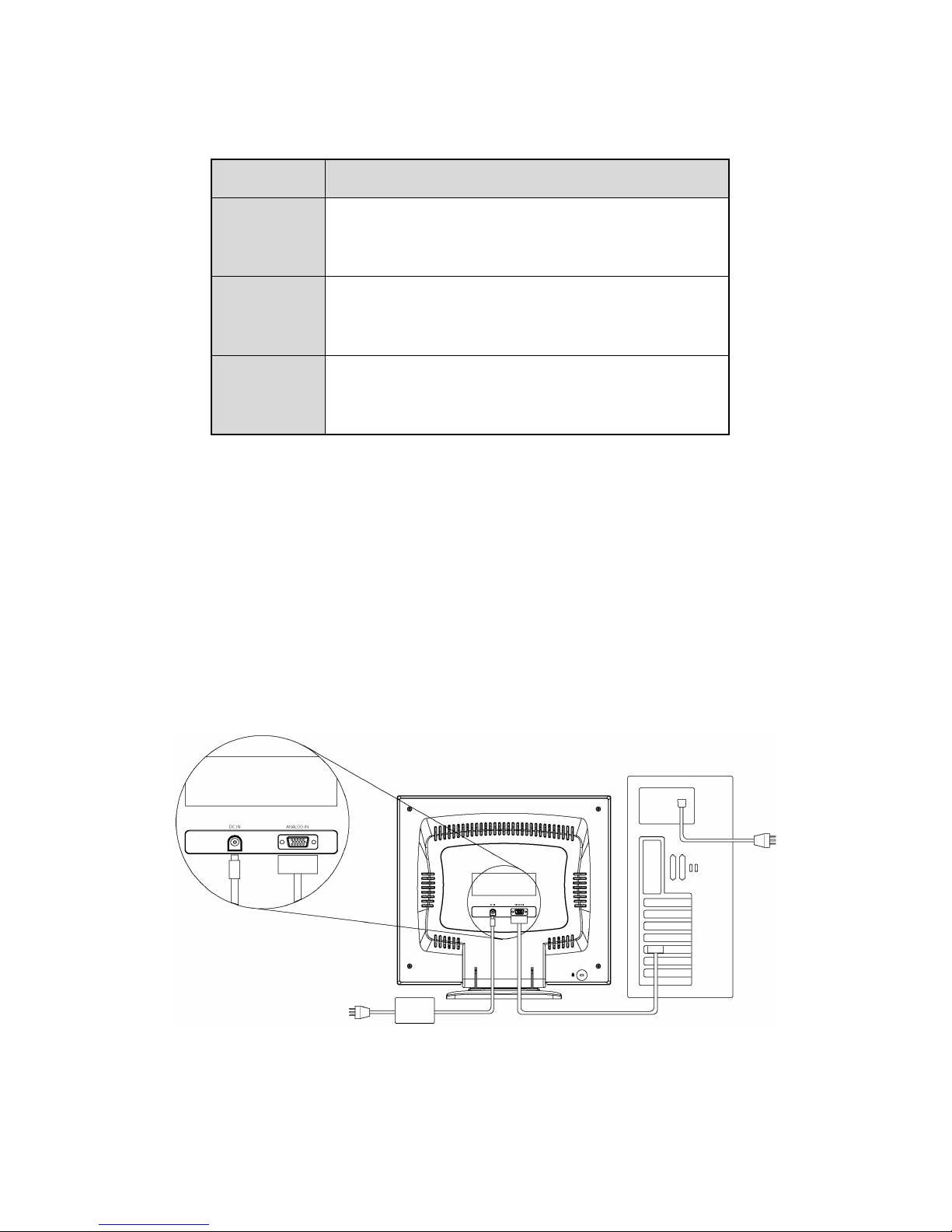
Making the Connections
Before connecting any cables, make sure that the computer and display are turn off.
To connect the power and video signal cables:
1. Locate the AC power adapter with attached power cable.
2. Connect the power cable to the power jack on the back of the display (as shown below).
3. Plug the two-prong power cord into a power outlet, and plug the other end into the AC power
adapter.
5
Page 8

4. Plug the analog video signal cable into the Analog Video Input port on the back of the display (as
shown above).
5. Connect the other end of the video cable into your computer’s video port. (Please check your
computer’s documentation if you’re not sure where the port is located.)
Note:
For best display performance, it is strongly recommended that you use Auto Setup to
automatically configure your display’s settings.
6
Page 9
Using Your Display
This chapter contains information about using your LCD Monitor.
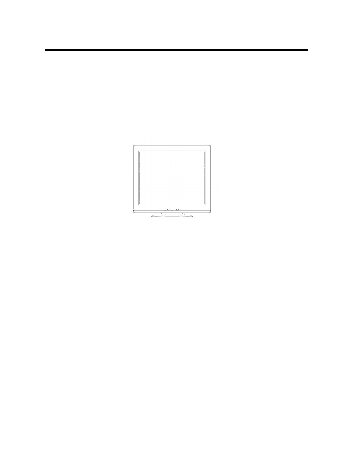
Turning the Display On and Off
Use the power button located at the lower right side of the front panel of the display to turn the display
on and off. When the display is on, the light (LED) near the Power button is illuminated. The light is
green when both the display and PC are active and amber when the display is in a reduced power
mode.
If your PC supplies power saving signals to the display, the display’s power management features
reduce power consumption to low levels when your PC goes into its power-saving mode. See
“Minimizing Power Consumption” on page 11 for more information.
If your PC doesn’t use industry standard power-save signaling techniques, you can reduce power
consumption by turning off the display when it won’t be used for an extended period. You can turn the
display off even if you leave your PC in running.
Note:
Because of the technology used in LCD panels, screen savers will not prolong the life of
your display. So if the display will not be used for an extended period, be sure to turn it off.
Warning
To completely disconnect power from your display, you must
remove the power cord from the wall outlet and then remove
the power cable from the display.
7
Page 10
Tilting the Display
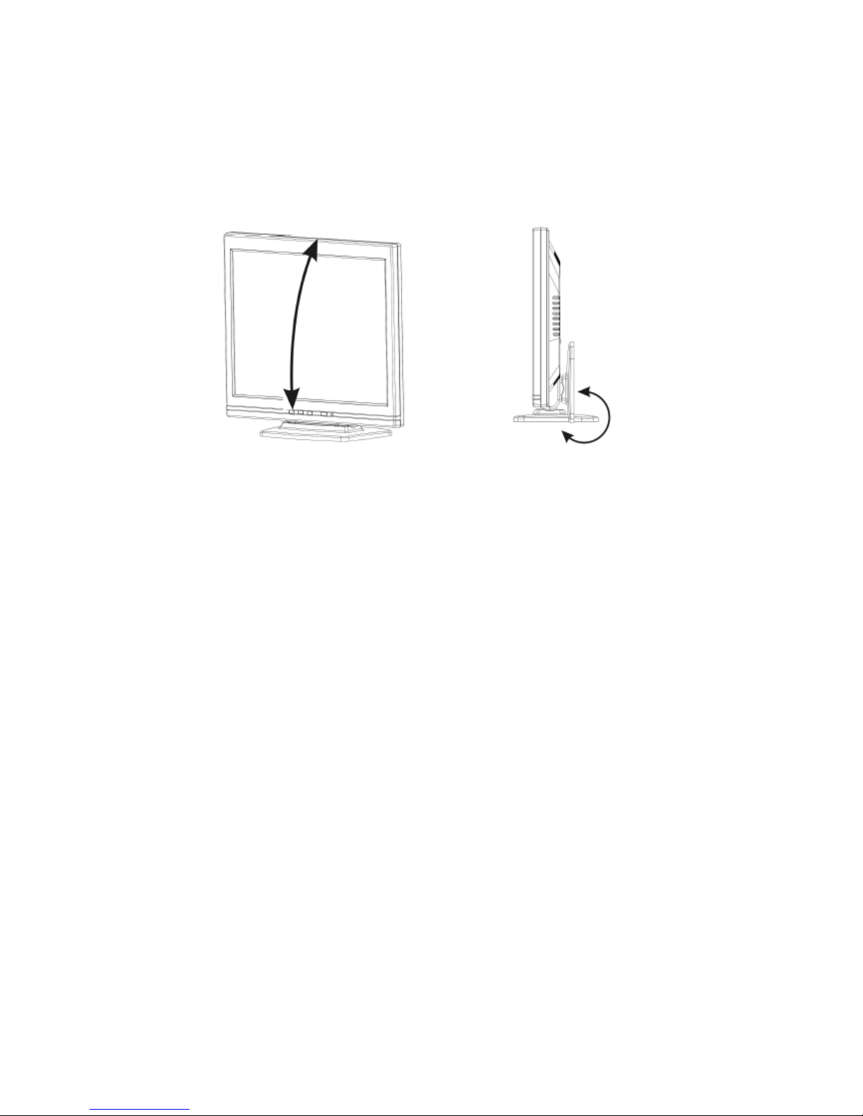
The monitors have a tilt feature that allows you to tilt the display back and forth as well as left and
right to find the most comfortable viewing position. To tilt the display, grasp the sides and push the
display back or pull it toward you, or turn it left or right until it is in the desired position. The display
can be tilted 20º backward and 5º forward.
Note:
Do not tilt the display by grasping the top edge.
Setting the Video Mode
Since the inherent format of this display is 1280 pixels by 1024 lines, the display will perform best
when your PC is set to a screen resolution of 1280 x 1024. If you use a lower resolution (such as 640
x 480), the image is expanded to fill the screen.
Your display supports many common video modes, as shown in “Video Modes” on page 29. Check
the documentation supplied with your PC and video adapter card to find out which modes they
support.
To see what the video mode in your Microsoft Windows, please check Windows’ settings in your PC.
Setting the Refresh Rate
The image refresh rate is the number of times per second that the image is refreshed; it is also known
as the vertical frequency.
On standard CRT displays, we recommend that you should use the highest possible refresh rate
supported by your PC at the current screen resolution. This is necessary to avoid screen flickering and
to minimize eyestrain. However, with your LCD Monitor, flicker is not an issue. It is flick-free at all
supported refresh rates.
8
Page 11
The table in “Video Mode” on page 29 shows the image refresh rates supported by the display at
different screen resolution. Although your LCD monitor supports up to 75 Hz for analog video input,
we recommend that you use 60 Hz refresh rate for best performance.
To set the refresh rate with a standard Windows installation, follow the steps mentioned in your
Windows’s or graphic card’s user’s manual.
Minimizing Power Consumption
Many PCs support industry standard power-save signaling techniques. Power management features
reduce the display’s power consumption after a period of keyboard inactivity.
When the display is in a power-saving mode, the screen is blank and the power indicator is amber.
Pressing a key on the keyboard or moving the mouse restores the image in several seconds. Consult
your PC documentation for information about setting the power-saving modes.
The display accepts the signals for standard power-saving mode, when PC go into power saving
mode . The display will go into power saving.
Caring for and Cleaning the Display
To maximize screen life and prevent damage to the LCD panel, we recommend that you:
Ö Use the display power management system (if available on your PC).
Ö If you don’t use a power management system, turn off the display when you won’t be using it for
an extended period.
Ö Don’t press, rub, or poke the display with your finger or other object.
Ö Handle your display with care.
Your LCD module is a high-quality optical device that requires special care when cleaning.
Warning
Don’t use liquid, aerosol, or abrasive cleaning solutions to
clean the screen.
To clean the screen:
1. Shut down the PC.
2. Turn off and unplug the display.
3. Gently dust the screen with a dry, soft, line-free cloth.
9
Page 12

Note:
If the screen is still dirty, you can dampen the cloth with several drops of distilled water.
Make sure the LCD panel is completely dry before you turn the display back on.
4. Plug in the display.
5. Turn on your PC and display.
10
Page 13

Adjusting Your Display
This chapter contains information about how to changing display settings for your LCD Monitor. It is
designed with an OSD menu to help you easily adjust to its optimum performance.
Note:
You must perform auto setup before making any adjustment.
Summary of Control Buttons
There are four control buttons located at the lower part of the front panel of your display:
Ö POWER: Push to turn on or turn off the display. The power indicator (Green) will light while the
display is on.
Ö Select: Display the On-Screen Display (OSD) “Main Menu” , selects items for user adjustment,
and execute the function selected.
Note:
Hold down this key for 2 seconds will clear OSD menu.
Ö Up(Ϧ): Move upward through the choice in the OSD submenu. If an adjustment bar is displayed,
this button increases the setting value.
Note:
This key is also used as ‘direct key’ to bring-up OSD “Brightness Adjust”.
Ö Down(ϯ): Move downward through the choice in the OSD submenu. If an adjustment bar is
displayed, this button decreases the setting value.
Note:
This key is also used as ‘direct key’. When the OSD “Main Menu” is inactive, press this key
will execute ‘Auto Setup’ function.
Displaying the OSD “Main Menu”
You can use the OSD features to change the screen settings of your display. To display the OSD
“Main Menu”, please press the ‘Select’ button.
The following table briefly describes each of the items in the OSD “Main Menu”.
11
Page 14
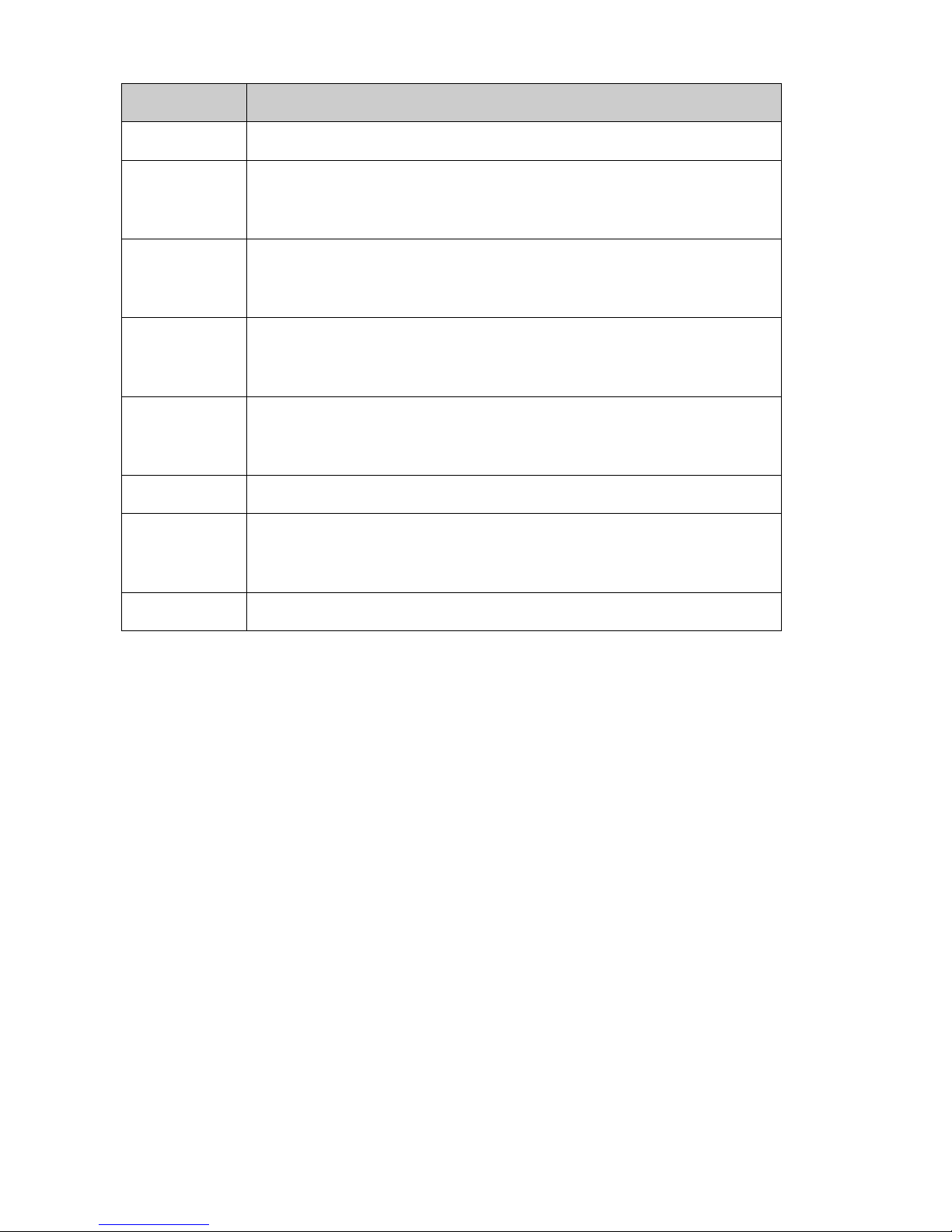
Item Description
Auto
Adjusting the “Auto Setup”. See “Adjusting Auto Setup” on page 14.
Management
Open the “Management” submenu where you can select Brightness,
Contrast or the image position for further adjustment. See Adjustment in the
“Management” Submenu” on page 15.
Clock/Phase
Open the “Clock/Phase” submenu where you can select Clock or Phase for
further adjustment. See Adjustment in the “Clock/Phase” Submenu” on
page 18.
Color
Open the “Color” submenu where you can select Color Temperature, RGB
and Black Level for further adjustment. See Adjustment in the “Color”
Submenu” on page 19.
OSD Display
Open the “OSD Display” submenu where you can select H. position or V.
position of the OSD display for further adjustment. See Adjustment in the
“OSD Display” Submenu” on page 21.
Factory Recall
Recall factory-setting values back. See Factory Recall” on page 22.
Languages
Open the “Languages” submenu where you can select one of the five
languages for your preference in display OSD messages. See “Selecting
Language for Your Preference” on page 23.
Exit
Clear and exit the OSD main menu.
Selecting Items in the OSD Menu
To select items in the OSD “Main Menu”, you will use the ‘Up (Ϧ)’ or ‘Down (ϯ)’ buttons on the
front panel of the display.
To select items in the OSD submenus, you will use all three, control buttons. To select a specific
submenu, you shall use ‘Up (Ϧ)’ or ‘Down (ϯ)’ buttons to move forward or backward to the item to
be adjusted, and then select it by press ‘Select’ button.
Adjusting the OSD Menu
Auto Setup
To perform the Auto Setup function you should follow the steps below:
1. Bring-up the OSD “Main Menu”.
12
Page 15
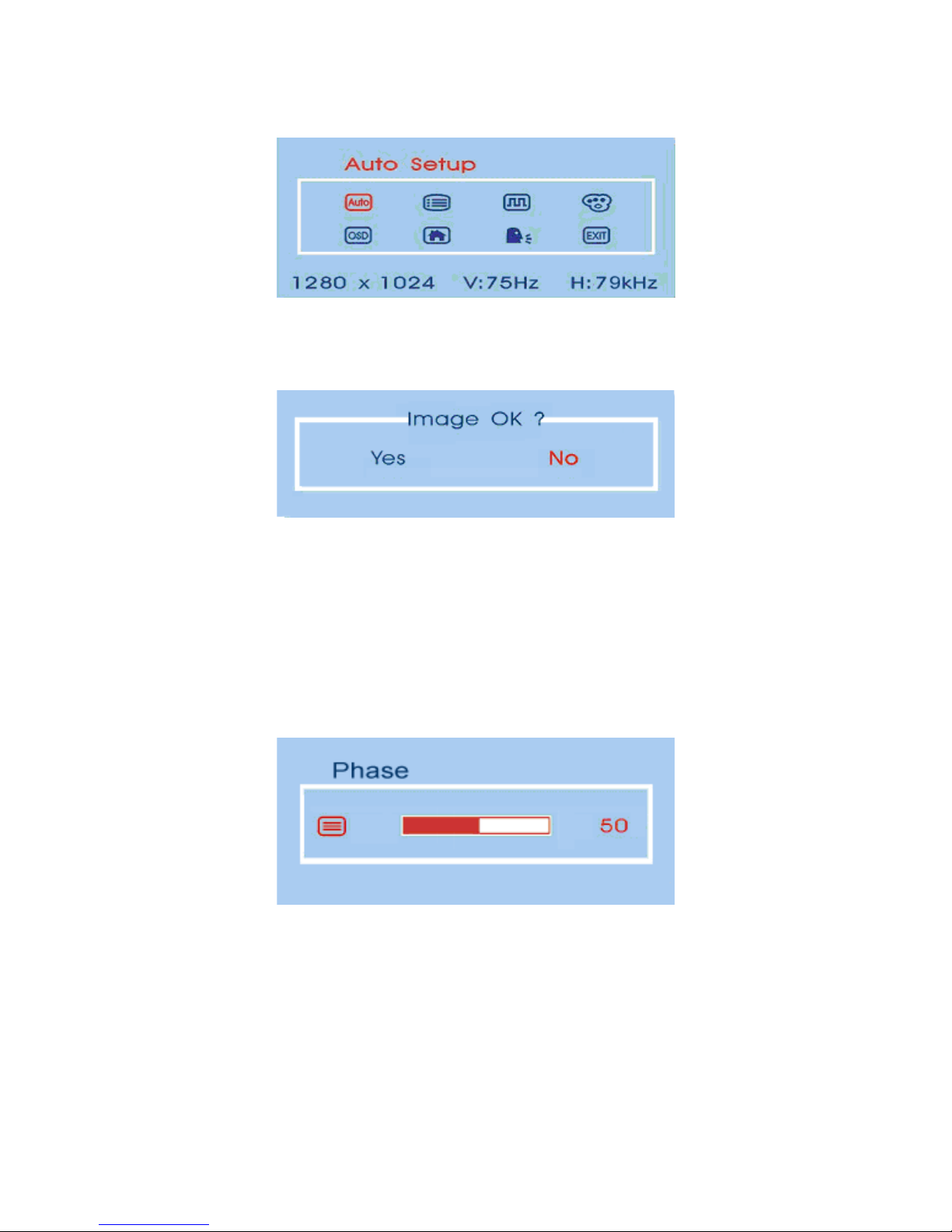
2. The ‘Auto’ icon should be highlighted already.
3. Use ‘Select’ button to select and execute the Auto Setup function. After the execution of the Auto
Setup function, it will show-up the follow message:
If the image looks correct, choose Ye s .
OR
If the image requires further adjustment, choose No, it will shown up ‘Phase’ bar for your further
adjustment by manual. Then you can adjust phase by ‘Up (Ϧ)’ or ‘Down (ϯ)’ buttons. When all
text appears well focused and there is no instability in the image, press the ‘Select’ key to end up
the adjustment.
Adjusting the “Management” Submenu
To perform the adjustment in the “Management” submenu you should follow the steps below:
1. Bring-up the OSD “Main Menu”.
2. Use ‘Up (Ϧ)’ (or ‘Down (ϯ)’) to move forward (or backward) to the management icon and
highlight it.
13
Page 16
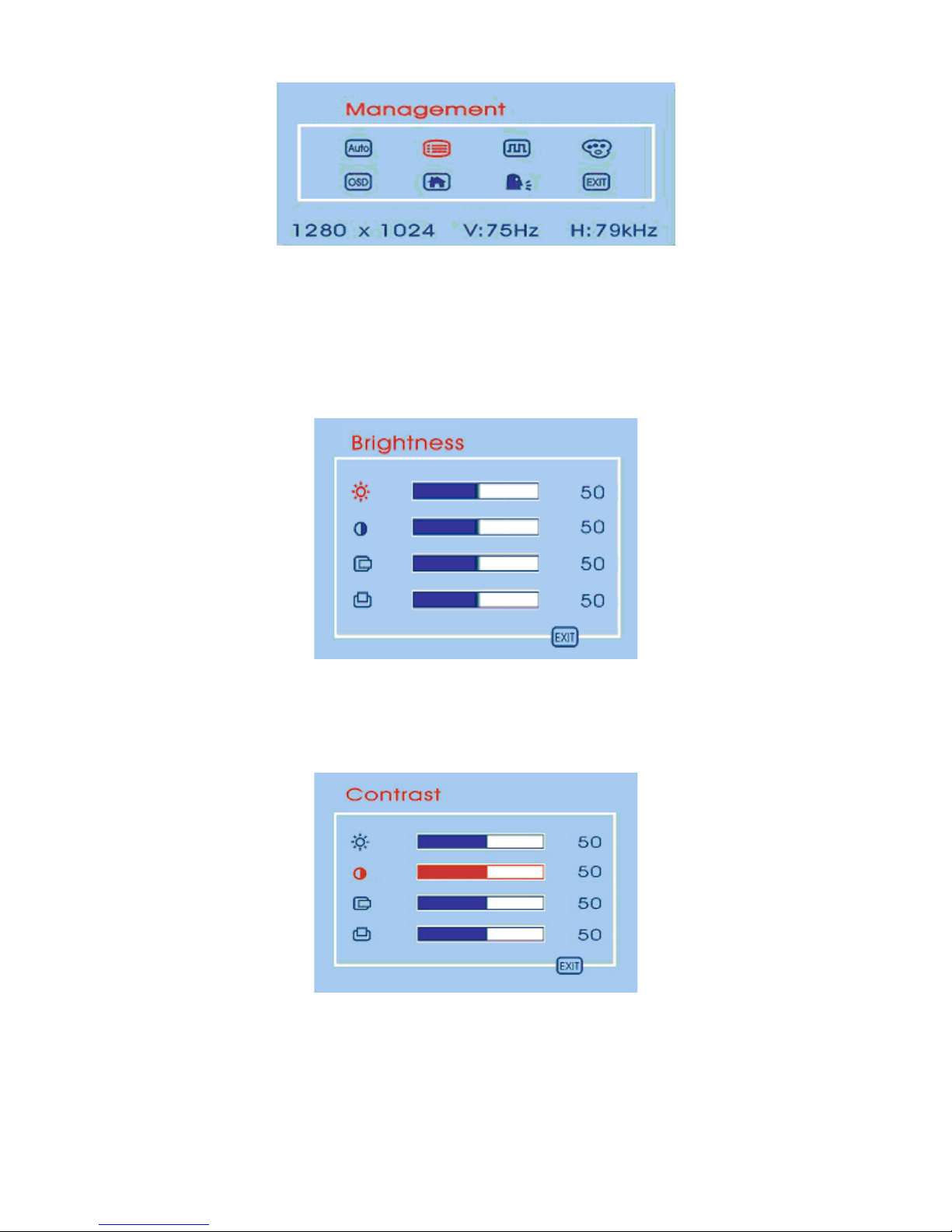
3. Use ‘Select’ key to enter the “Management” Submenu. It will show up four items for your further
adjustment.
If ‘Brightness’ is selected, you may use ‘Up (Ϧ)’ or ‘Down (ϯ)’ buttons to adjust the setting of
brightness. The fullness of the graphic bar as well as the numerical value at the right corner is also
changed accordingly.
If ‘Contrast’ is selected, you may use ‘Up (Ϧ)’ or ‘Down (ϯ)’ buttons to adjust the setting of
contrast. The fullness of the graphic bar as well as the numerical value at the right corner is also
changed accordingly.
Note:
We recommend you do Auto Setup before adjusting the contrast setting.
14
Page 17
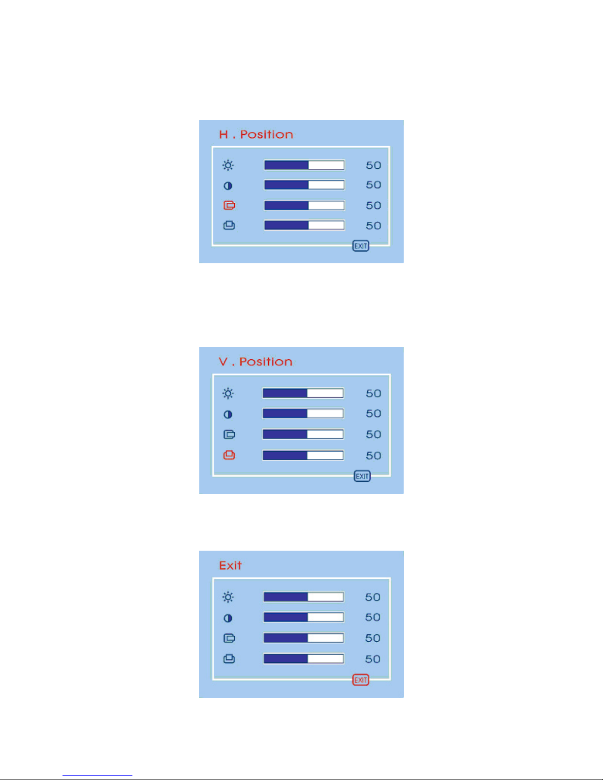
If ‘H. position’ is selected, you may use ‘Up (Ϧ)’ or ‘Down (ϯ)’ buttons to adjust the setting of
the horizontal position of the image. The fullness of the graphic bar as well as the numerical
value at the right corner is also changed accordingly.
If ‘V. position’ is selected, you may use ‘Up (Ϧ)’ or ‘Down (ϯ)’ buttons to adjust the setting of
the vertical position of the image. The fullness of the graphic bar as well as the numerical value at
the right corner is also changed accordingly.
If ‘Exit’ is selected, it will exit the “Management” submenu and go back to the “Main Menu”.
15
Page 18
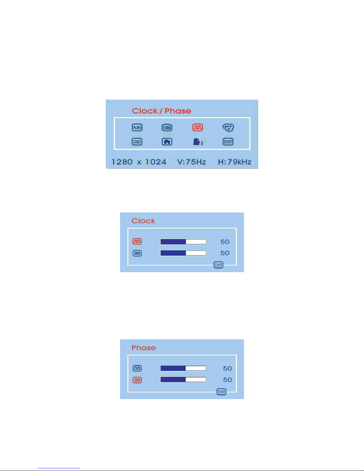
Adjusting the “Clock/Phase” Submenu
To adjust the “Clock/Phase” submenu you should follow the steps below:
1. Bring-up the OSD “Main Menu”.
2. Use ‘Up (Ϧ)’ (or ‘Down (ϯ)’) to move forward (or backward) to the clock/phase icon and
highlight it.
3. If ‘Clock’ is selected, you may use ‘Up (Ϧ)’ or ‘Down (ϯ)’ buttons to adjust the setting of clock.
The fullness of the graphic bar as well as the numerical value at the right corner is also changed
accordingly.
Note:
We recommend you perform the Auto Setup first. And adjust the clock setting only if the
image looks incorrect.
If ‘Phase’ is selected, you may use ‘Up (Ϧ)’ or ‘Down (ϯ)’ buttons to adjust the setting of phase.
The fullness of the graphic bar as well as the numerical value at the right corner is also changed
accordingly.
Note:
We recommend you perform the Auto Adjust before adjusting the phase.
16
Page 19
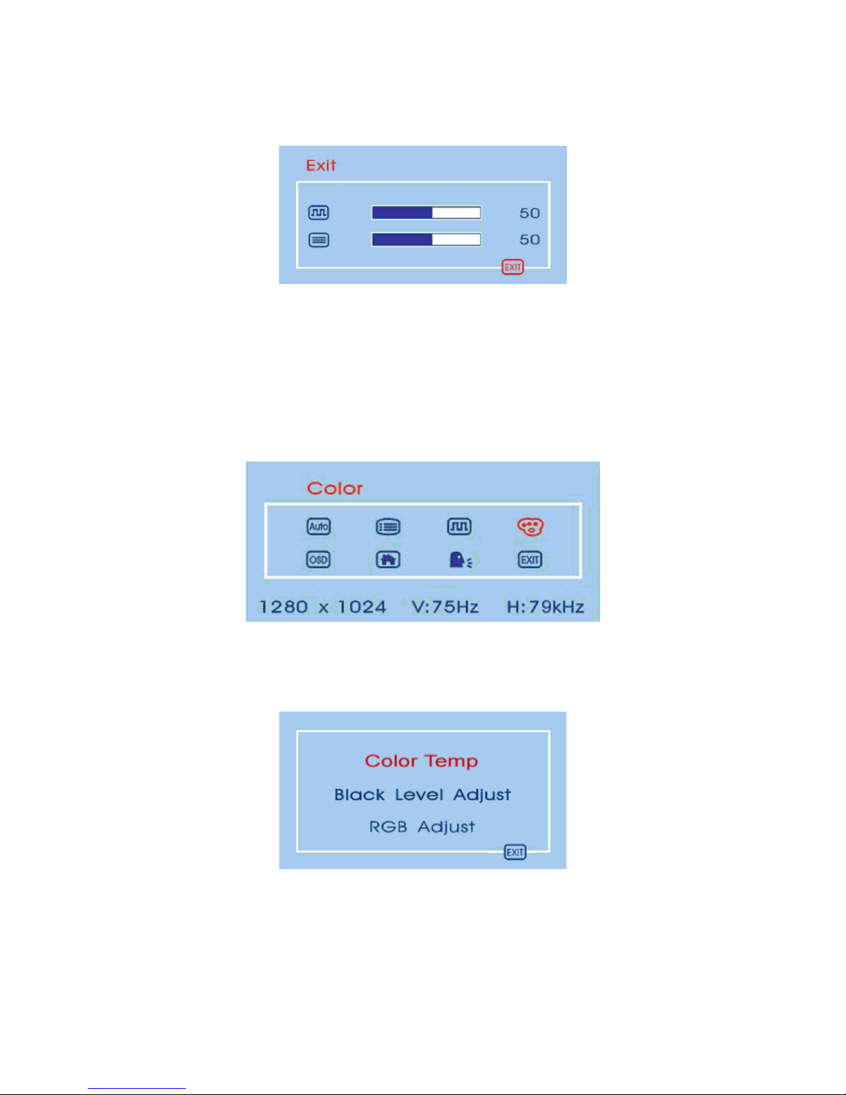
If ‘Exit’ is selected, it will exit the “Clock/Phase” submenu and go back to the “Main Menu”.
Adjusting the “Color” Submenu
To do adjustment in the “Color” submenu you should follow the steps below:
1. Bring-up the OSD “Main Menu”.
2. Use ‘Up (Ϧ)’ (or ‘Down (ϯ)’) to move forward (or backward) to the color icon and highlight it.
3. Use ‘Select’ button to enter the “Color” submenu. It will show up three items for your further
adjustment.
If ‘Color Temp’ is selected, you may use ‘Up (Ϧ)’ or ‘Down (ϯ)’ buttons to select one of the
three settings. Press ‘Select’ button will return you back to the “Color” submenu.
17
Page 20
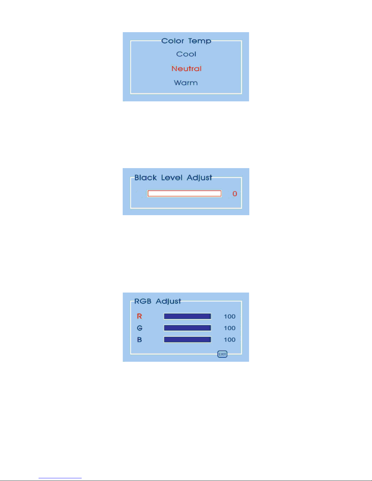
Note:
As you choose an item, your screen immediately updates to reflect this setting.
If ‘Black Level Adjust’ is selected, it will bring-up “Back Level Adjust” submenu. You can
adjust its setting by ‘Up (Ϧ)’ and ‘Down (ϯ)’ buttons.
If ‘RGB Adjust’ is selected, it will bring-up “RGB Adjust” submenu. Use ‘Up (Ϧ)’ or ‘Down
(ϯ)’ buttons to choose and highlight one of the three options (Red, Green and Blue) and then use
‘Select’ button to select it. This will show-up the corresponding bar on menu, and you can adjust
its setting by ‘Up (Ϧ)’ and ‘Down (ϯ)’ buttons. This control may be helpful in achieving a
more natural appearance in graphic images and closer color matching between the printer and the
display.
If ‘Exit’ is selected, it will exit the “Color” submenu and go back to the “Main Menu”.
18
Page 21
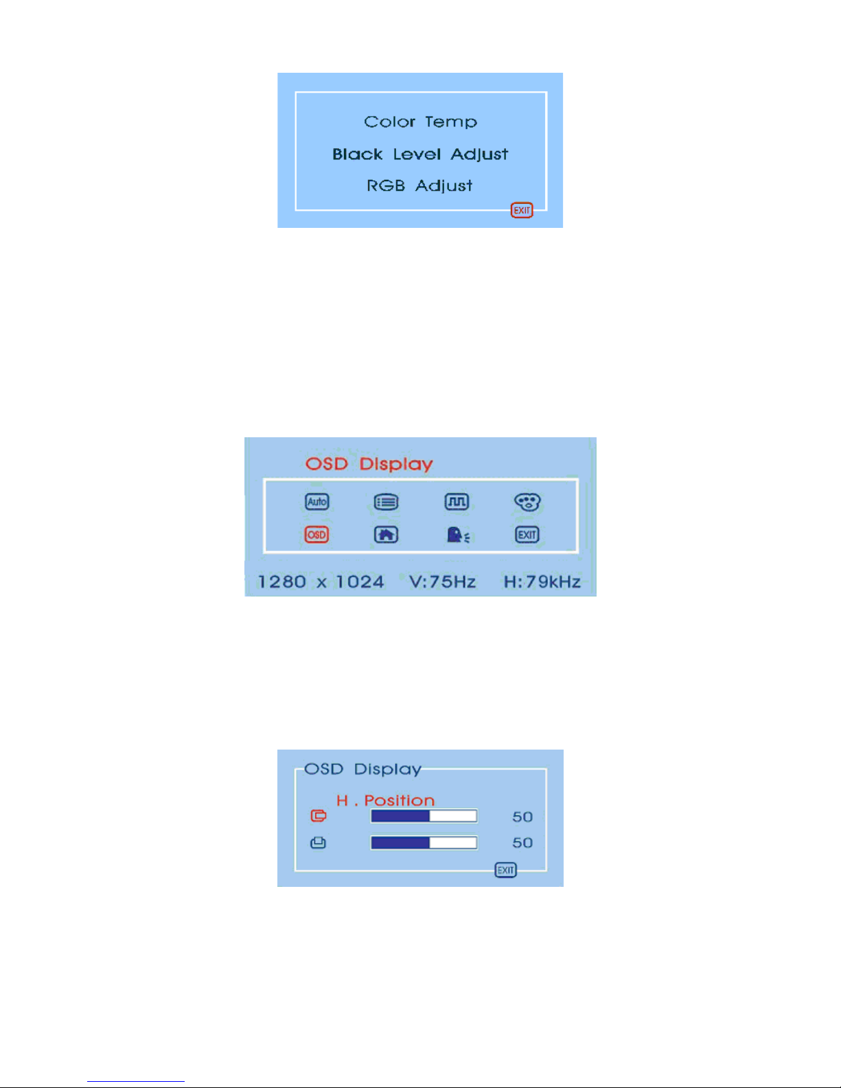
Adjusting the “OSD Display” submenu
To adjust the OSD H and V, positions you should follow the steps below:
1. Bring-up the OSD “Main Menu”.
2. Use ‘Up (Ϧ)’ (or ‘Down (ϯ)’) to move forward (or backward) to the OSD display icon and
highlight it.
3. Use ‘Select’ button to enter the “OSD Display” submenu. It will show up two items for your
further adjustment.
If ‘H. Position’ is selected, you may use ‘Up (Ϧ)’ or ‘Down (ϯ)’ buttons to adjust the setting of
H. position of the OSD display. The fullness of the graphic bar as well as the numerical value at
the right corner is also changed accordingly.
If ‘V. Position’ is selected, you may use ‘Up (Ϧ)’ or ‘Down (ϯ)’ buttons to adjust the setting of
V. position of the OSD display. The fullness of the graphic bar as well as the numerical value at
the right corner is also changed accordingly.
19
Page 22
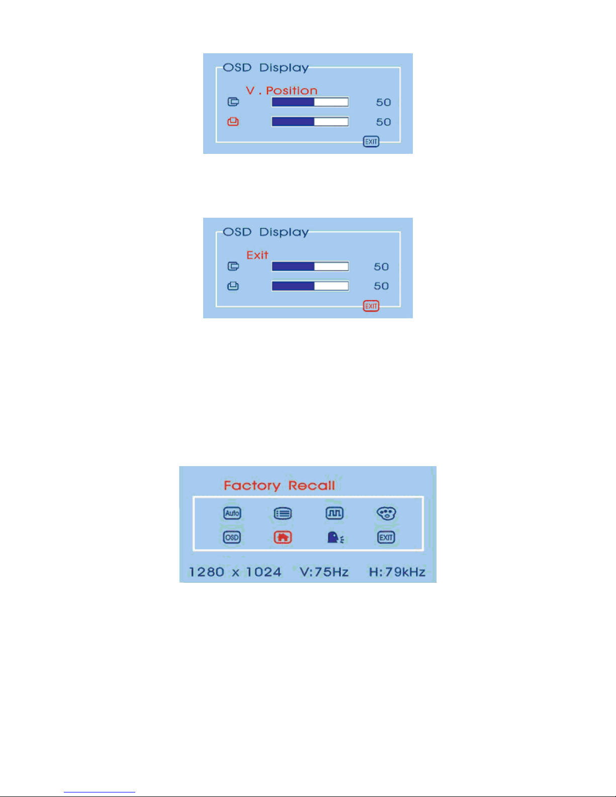
If ‘Exit’ is selected, it will exit the “OSD Display” submenu and go back to the “Main Menu”.
Adjusting the Factory Recall
To recall factory settings back you should follow the steps below:
1. Bring-up the OSD “Main Menu”.
2. Use ‘Up (Ϧ)’ (or ‘Down (ϯ)’) to move forward (or backward) to the factory recall icon and
highlight it.
3. Use ‘Select’ button to activate the factory recall action.
20
Page 23
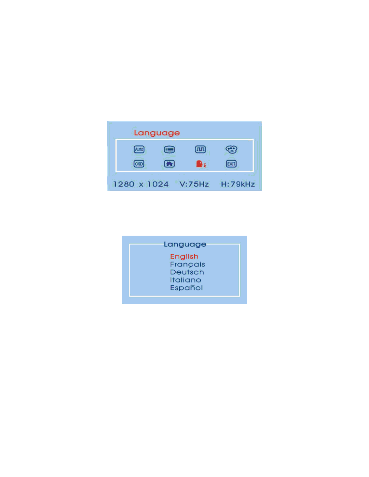
Selecting Language for Your Preference
To select one of the five languages for your preference you should follow the steps below:
1. Bring-up the OSD “Main Menu”.
2. Use ‘Up (Ϧ)’ (or ‘Down (ϯ)’) to move forward (or backward) to the languages icon and
highlight it.
3. Use ‘Select’ button to enter the “Language” submenu. It will show up five items for your
selection. Use ‘Up (Ϧ)’ (or ‘Down (ϯ)’) to move forward (or backward) to the languages you
prefer and Press ‘Select’ button to select it.
Note:
As you choose an item, your OSD information displayed immediately updates to reflect
this setting.
Exit and Clear the OSD Menu
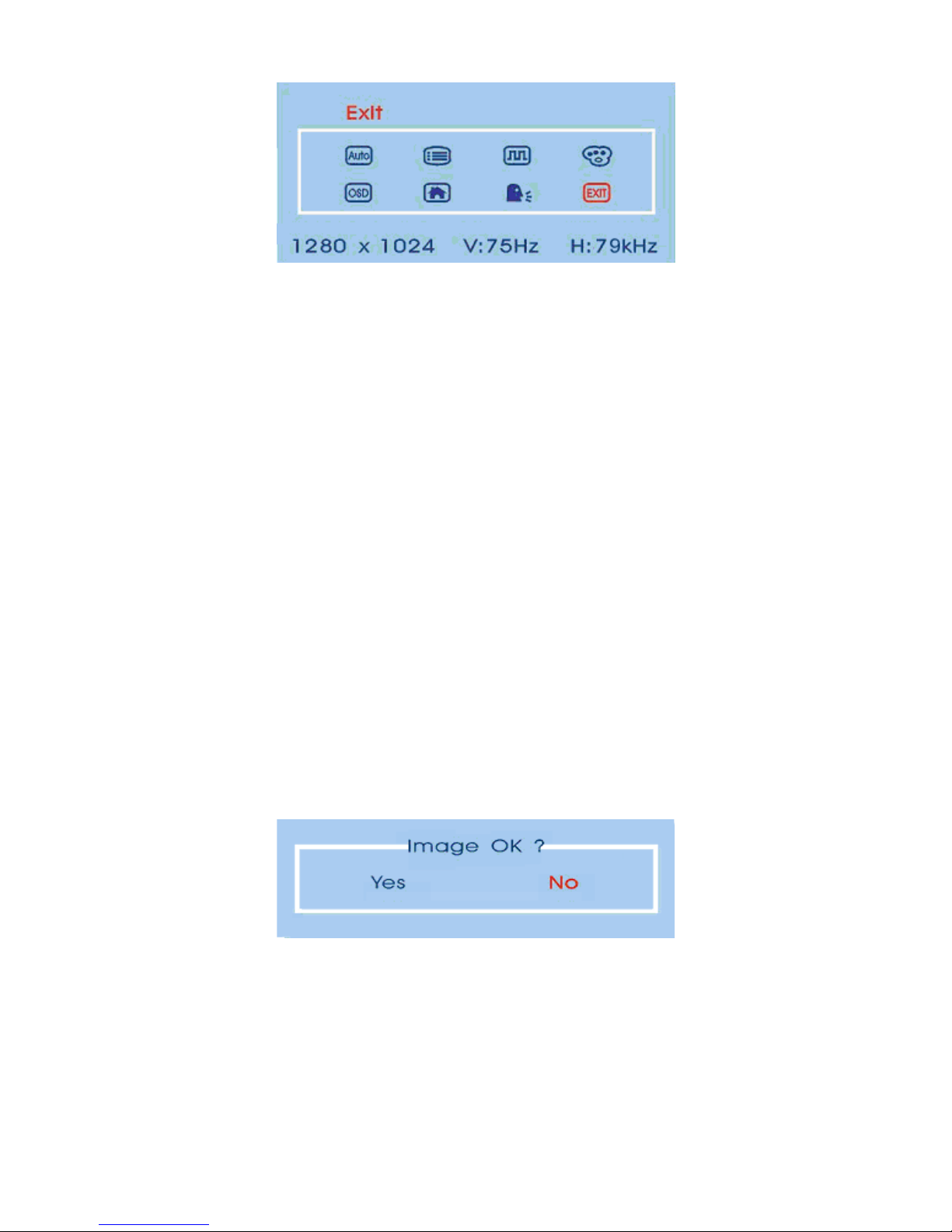
To exit and clear the OSD menu you should use ‘Up (Ϧ)’ (or ‘Down (ϯ)’) to move forward (or
backward) to the exit icon and select it by ‘Select’ button.
21
Page 24
Using the Direct Keys
There are two direct keys that function while OSD “Main Menu” is inactivated. One of the two direct
keys is for Auto Setup and the other is for bringing-up OSDϘBrightnessϙmenu.
Auto Setup by Direct Key
Use Auto Setup whenever you apply a new video mode or change the refresh rate. While the Auto
Setup routine is running, you should have a stable image displayed on the screen. Do not move items
around the screen, play games, or view video during Auto Setup.
Once you have executed Auto Setup for a particular mode, the display will store the new values in its
permanent memory.
To execute Auto Setup by direct key
1. Press ‘Down (ϯ)’ button with no OSD “Main Menu” displayed on screen, this will start the
execution of Auto Setup.
The image will change color and appear to jitter during the Auto Setup function. After the function
is complete, you are asked whether the image appears correct or not.
2. If the image looks correct, choose Ye s, and then the OSD will close automatically.
22
Page 25

If the image requires further adjustment, choose No, it will shown up ‘Phase’ bar for your further
adjustment by manual. Then you can adjust the phase by ‘Up (Ϧ)’ or ‘Down (ϯ)’ buttons. When
all text appears well focused and there is no instability in the image, press the ‘Select’ key to end
the adjustment and close the OSD menu.
23
Page 26

Troubleshooting
This chapter contains information about how to troubleshoot your LCD Monitor. If you have tried all
of the items listed below, please contact a qualified service personnel.
A. My display doesn’t work, even though the computer appears to work.
1. Make sure the power cable is securely plugged into the display.
2. Make sure the display is turned on.
3.
Try turning the display off and then turning it on again.
4.
Make sure the display’s power cord is plugged into a power outlet and into the AC power adapter.
Check to see whether the outlet works by plugging another device (such as a lamp) into the
outlet. (If the light on the front of the display is lighted, it is getting power. Try the next item on
this procedure.)
5.
Check the cable connection between the display and the computer. The cable connectors must be
pushed in all the way.
B. The message “Check Cable” appears on my display.
This message appears when the video cable is not properly connected to the computer.
1. Make sure the analog video cable is plugged into the Analog Video Input port on the back of the
display.
2.
Make sure the other end of analog video cable is plugged into the PC’s video port.
C. The message “No Sync.” appears on my display.
This message appears when there is no video signal from the computer with cable already connected.
1. Make sure that the computer's power is turn on.
2.
Make sure that your graphic card has its output already.
D. The message “Signal Out of Range” appears on my display.
This message appears when the input signal is beyond the display's capability.
Set your PC to a supported video mode, preferably 1280 x 1024 at 60 Hz. See “Setting the Video
Mode” on page 10.
24
Page 27
E. The image is very unstable.
1. Set your PC to a supported video mode, preferably 1280 x 1024 at 60 Hz. See “Setting the Video
Mode” on page 10.
2.Restore the original factory settings by choosing Factory Recall in the OSD “Factory Recall”
submenu.
3.
Perform the Auto Setup function. See “Auto Setup by Direct Key” on page 24.
Note:
Even if your PC’s setting is out of the range of video modes that are supported by your
LCD monitor, it may still be displayed with reduced quality. This provides you with an
opportunity to change your PC’s setting to a correct one.
25
Customer Support
Before contacting ViewSonic Customer Support, check the Troubleshooting section for possible
solutions to any setup problems. For Customer Support or product service, you will need to provide
the product serial number
Country/Region Website
T = Telephone
F = FAX
United States www.viewsonic.com/support T: (800) 688-6688
F: (909) 468-1202
Canada www.viewsonic.com/support T: (866) 463-4775
F: (909) 468-1202
Page 28
Technical Information
26
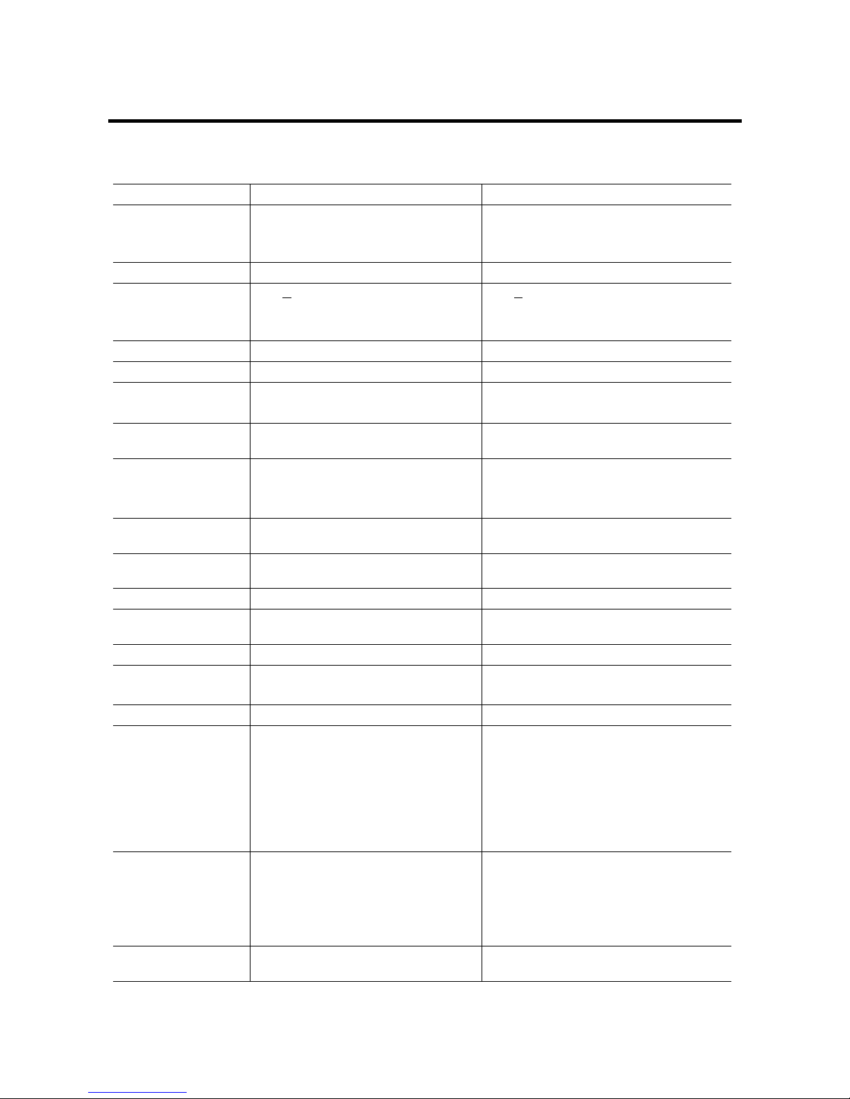
Specifications
VTA700 VTA900
LCD Module 17-inch, active matrix TFT,
Anti-glare coating,
0.264 mm pixel pitch
19-inch, active matrix TFT,
Anti-glare coating,
0.264 mm pixel pitch
Display Size 337.9 mm x 270.3 mm 376.32 mm x 301.056 mm
Viewing Angle:
Left/Right
Up/Down
CR >
5
-85º / 85º (Typical)
-85º / 85º (Typical)
CR > 5
-85º / 85º (Typical)
-85º / 85º (Typical)
Contrast Ratio 500:1 (Typ), 450:1 (Min) 500:1 (Typ), 450:1 (Min)
Display Colors 16.2 Million 16.7 Million
Power Input 100 ~ 240 V
AC
Full Range,
50/60 Hz (External AC adapter)
100 ~ 240 V
AC
Full Range,
50/60 Hz (External AC adapter)
Maximum power
consumption
40 W 45 W
Signal Input:
Video Signal
Sync signals
RGB positive 0.7V
PP
, 75ohm
Separate, TTL Level
RGB positive 0.7VPP, 75ohm
Separate, TTL Level
Line (horizontal)
frequency
30 kHz ~ 82 kHz 30 kHz ~ 82 kHz
Raster (vertical)
frequency
50 Hz ~ 76 Hz 50 Hz ~ 76 Hz
Pixel dot clock 135 MHz (maximum) 135 MHz (maximum)
Recommended
mode
1280 x 1024 @ 60 Hz 1280 x 1024 @ 60 Hz
Pedestal tilt -5º forward, 20º backward -5º forward, 20º backward
Dimensions 403 (W) x 382 (H) x 192 mm (D)
(without base)
442.5 (W) x 418.35 (H) x 192 mm (D)
(without base)
Weight 4.75 kg 6.4 kg
Operating
Conditions:
Temperature
Humidity
Altitude
5º ~ 40ºC at altitude 0 ~ 2000m
5º ~ 30ºC at altitude
2000 ~ 3000m
20% ~ 85% RH, non-condensing
3000m Max.
5º ~ 40ºC at altitude 0 ~ 2000m
5º ~ 30ºC at altitude 2000 ~ 3000m
20% ~ 85% RH, non-condensing
3000m Max.
Storage
Conditions:
Temperature
Humidity
Altitude
-20º ~ 60ºC
5% ~ 95% RH
10,000m Max.
-20º ~ 60ºC
5% ~ 95% RH
10,000m Max.
Maximum
Resolution
1280 x 1024 @ 75 Hz 1280 x 1024 @ 75 Hz
Page 29
Video Modes
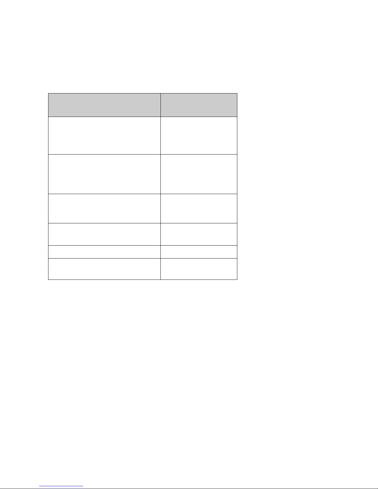
Your LCD monitor supports the following industry-standard combinations of screen resolution and
refresh rates. Other combinations are possible, but may require adjustments to the image.
For optimum performance, set your PC to a screen resolution of 1280 x 1024 at a 60 Hz refresh rate.
Supported Resolution
(dots x lines)
Vertical Frequency
(Refresh Rate)
VGA
640 x 480
640 x 480
640 x 480
640 x 350
60 Hz
72 Hz
75 Hz
70 Hz
SVGA 800 x 600
800 x 600
800 x 600
800 x 600
56 Hz
60 Hz
72 Hz
75 Hz
XGA 1024 x 768
1024 x 768
1024 x 768
60 Hz
70 Hz
75 Hz
SXGA 1280 x 1024
1280 x 1024
60 Hz
75 Hz
US TEXT 720 x 400 70 Hz
Power MAC 640 x 480
832 x 624
67 Hz
75 Hz
Note:
The display is capable of going beyond these recommended modes.
Unknown Video Modes
Like all other monitors, the your LCD monitor is designed to work with standard video modes.
However, not all video/graphic cards use only standard display modes.
Your LCD monitor uses state-of-the-art technology, which is designed to synchronize to any display
mode. We recommend choosing one of the supported modes listed above. If you choose an unknown
mode, you will need to manually adjust the clock, phase, and image position.
If you must use an unknown mode, you can run Auto Setup at first. If Auto Setup doesn’t provide
adequate image adjustment, then you must manually adjust the clock, phase, horizontal position, and
vertical position.
27
Page 30

Regulatory Information
Agency Approvals
USA
UL1950
FCC Class B
FCC Statement: FCC Notice – Part 15
This device complies with Part 15 of FCC rules. Operation is subject to the following two conditions:
(1) This device may not cause harmful interference.
(2) This device must accept any interference received. Including interference that may cause
undesired operation.
28
MPRII
Energy Star
Page 31

Limited Warranty
29
VIEWSONIC LCD DISPLAY
What the warranty covers:
ViewSonic warrants its products to be free from defects in material and workmanship during the
warranty period. If a product proves to be defective in material or workmanship during the warranty
period, ViewSonic will, at its sole option, repair or replace the product with a like product. Replacement
product or parts may include remanufactured or refurbished parts or components.
How long the warranty is effective:
ViewSonic
®
LCD displays are warranted for three (3) years for all parts including the light source and
three (3) years for all labor from the date of the first consumer purchase.
Who the warranty protects:
This warranty is valid only for the first consumer purchaser.
What the warranty does not cover:
1. Any product on which the serial number has been defaced, modified or removed.
2. Damage, deterioration or malfunction resulting from:
a. Accident, misuse, neglect, fire, water, lightning, or other acts of nature, unauthorized product
modification, or failure to follow instructions supplied with the product.
b. Repair or attempted repair by anyone not authorized by ViewSonic.
c. Any damage of the product due to shipment.
d. Removal or installation of the product.
e. Causes external to the product, such as electrical power fluctuations or fail
ure.
f. Use of supplies or parts not meeting ViewSonic’s specifications.
g. Normal wear and tear.
h. Any other cause which does not relate to a product defect.
3. Removal, installation, and set-up service charges.
How to get service:
1. For information about receiving service under warranty, contact ViewSonic Customer Support.
Yo u will need to provide your product's serial number.
2. To obtain service under warranty, you will be required to provide (a) the original dated sales slip, (b) your
name, (c) your address, (d) a description of the problem, and (e) the serial number of the product.
3. Take or ship the product freight prepaid in the original container to an authorized ViewSonic ser-
vice center or ViewSonic.
4. For additional information or the name of the nearest ViewSonic service center, contact
ViewSonic.
Limitation of implied warranties:
THERE ARE NO WARRANTIES, EXPRESS OR IMPLIED, WHICH EXTEND BEYOND THE
DESCRIPTION CONTAINED HEREIN INCLUDING THE IMPLIED WARRANTY OF
MERCHANTABILITY AND FITNESS FOR A PARTICULAR PURPOSE.
Exclusion of damages:
VIEWSONIC'S LIABILITY IS LIMITED TO THE COST OF REPAIR OR REPLACEMENT OF THE
PRODUCT. VIEWSONIC SHALL NOT BE LIABLE FOR:
1. DAMAGE TO OTHER PROPERTY CAUSED BY ANY DEFECTS IN THE PRODUCT, DAMAGES
BASED UPON INCONVENIENCE, LOSS OF USE OF THE PRODUCT, LOSS OF TIME, LOSS OF
PROFITS, LOSS OF BUSINESS OPPORTUNITY, LOSS OF GOODWILL, INTERFERENCE WITH
BUSINESS RELATIONSHIPS, OR OTHER COMMERCIAL LOSS, EVEN IF ADVISED OF THE
POSSIBILITY OF SUCH DAMAGES.
2. ANY OTHER DAMAGES, WHETHER INCIDENTAL, CONSEQUENTIAL OR OTHERWISE.
3. ANY CLAIM AGAINST THE CUSTOMER BY ANY OTHER PARTY.
Effect of state law:
This warranty gives you specific legal rights, and you may also have other rights which vary from state
to state. Some states do not allow limitations on implied warranties and/or do not allow the exclusion of
incidental or consequential damages, so the above limitations and exclusions may not apply to you.
Sales outside the U.S.A. and Canada:
For warranty information and service on ViewSonic products sold outside of the U.S.A. and Canada,
contact ViewSonic
or your local ViewSonic dealer.
ViewSonic LCD Warranty (V3.0) Release Date: 01-29-2002
Page 32

9LHZ6RQLF
 Loading...