

Page 1
Service Manual
ViewSonic VT2645-M
Model No. VS12675
26” LCD TV
(VT2645-M_SM Rev. 1b Apr. 2010)
ViewSonic® 381 Brea Canyon Road, Walnut, California 91789 USA - (800) 888-8583
Page 2
Copyright
1
Copyright© 2010 by ViewSonic Corporation. All rights reserved. No part of this publication may be
reproduced, transmitted, transcribed, stored in a retrieval system, or translated into any language or
computer language, in any form or by any means, electronic, mechanical, magnetic, optical, chemical,
manual or otherwise, without the prior written permission of ViewSonic Corporation.
Disclaimer
ViewSonic makes no representations or warranties, either expressed or implied, with respect to the contents
hereof and specifically disclaims any warranty of merchantability or fitness for any particular purpose. Further,
ViewSonic reserves the right to revise this publication and to make changes from time to time in the contents
hereof without obligation of ViewSonic to notify any person of such revision or changes.
Trademarks
Optiquest is a registered trademark of ViewSonic Corporation.
ViewSonic is a registered trademark of ViewSonic Corporation.
All other trademarks used within this document are the property of their respective owners.
Revision History
Revision SM Editing Date ECR Number Description of Changes Editor
1a 12/22/09 Initial Release Sophia Kao
1b 04/06/10 Add Factory & Hospitality mode Sophia Kao
ViewSonic Corporation Confidential - Do Not Copy VT2645-M
Page 3
UTABLE OF CONTENTS
2
Item Page
1. Precautions and Safety Notices 3
2. Product Specification 6
3. Function Description 10
4. Block Diagram 16
5. Exploded Diagram and Exploded Parts List 17
6. Disassembly Procedure 20
7. Recommended Spare Parts List 33
8. BIOS /Firmware Update SOP 34
9. Trouble Shooting Flow Chart 57
10. FAQ 61
ViewSonic Corporation Confidential - Do Not Copy VT2645-M
Page 4
1. Precautions and Safety Notices
3
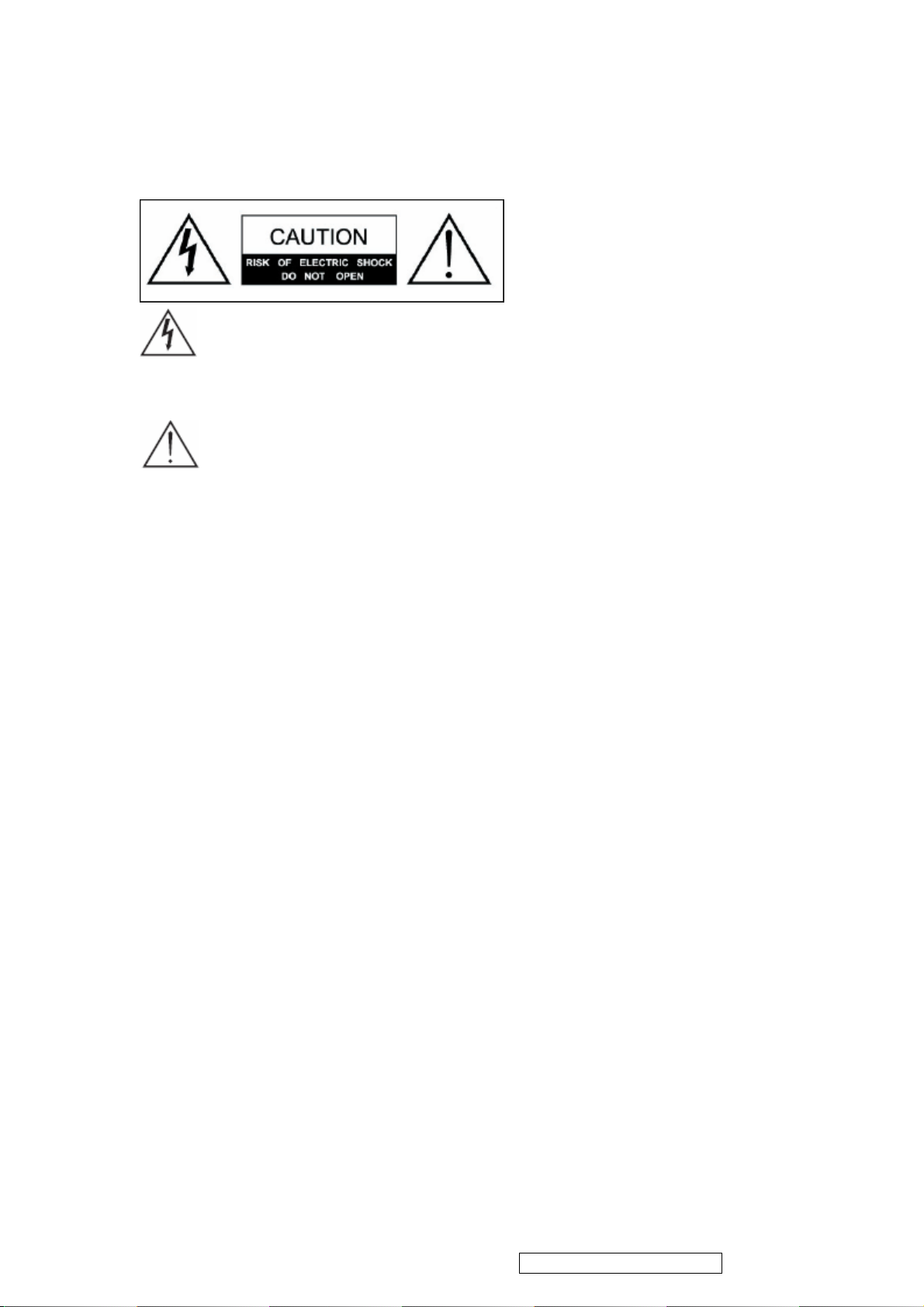
Safety Instructions
The symbol is intended to alert the user to presence of un-insulated
“Hazardous Voltage” within the product’s enclosure that may be of sufficient
magnitude to constitute a risk of electric shock to persons.
This symbol is intended to alert the user that improper use of the product
may result in product malfunction. The user should pay attention to avoid accidents or
unnecessary problems.
Wet Location
Apparatus shall not be exposed to dripping or splashing and that no objects filled with
liquids, such as vases, shall be placed on the apparatus.
Outdoor Use
WARNING: To reduce the risk of fire or electric shock, do not expose this apparatus
to rain or moisture.
Disconnect Device - The Mains Plug or An Appliance Coupler
The mains plug or an appliance coupler is used as the disconnect device for
disconnection from the mains, the disconnect device shall remain readily operable.
Safety
Operate the TV on 100V and 120V AC only.
Use the AC power cord specified by ViewSonic and suitable for the voltage where you
use it.
The plug is designed, for safety purposes, to fit into the wall outlet only one way.
If you are unable to insert the plug fully into the outlet, contact your dealer.
If any liquid or solid object should fall inside the cabinet, stop operating, unplug the TV
immediately and have it checked by qualified service technician.
If you will not be using the TV for a long time, disconnect the power by pulling the plug
itself. Do not pull on the cord.
ViewSonic Corporation Confidential - Do Not Copy VT2645-M
Page 5
4
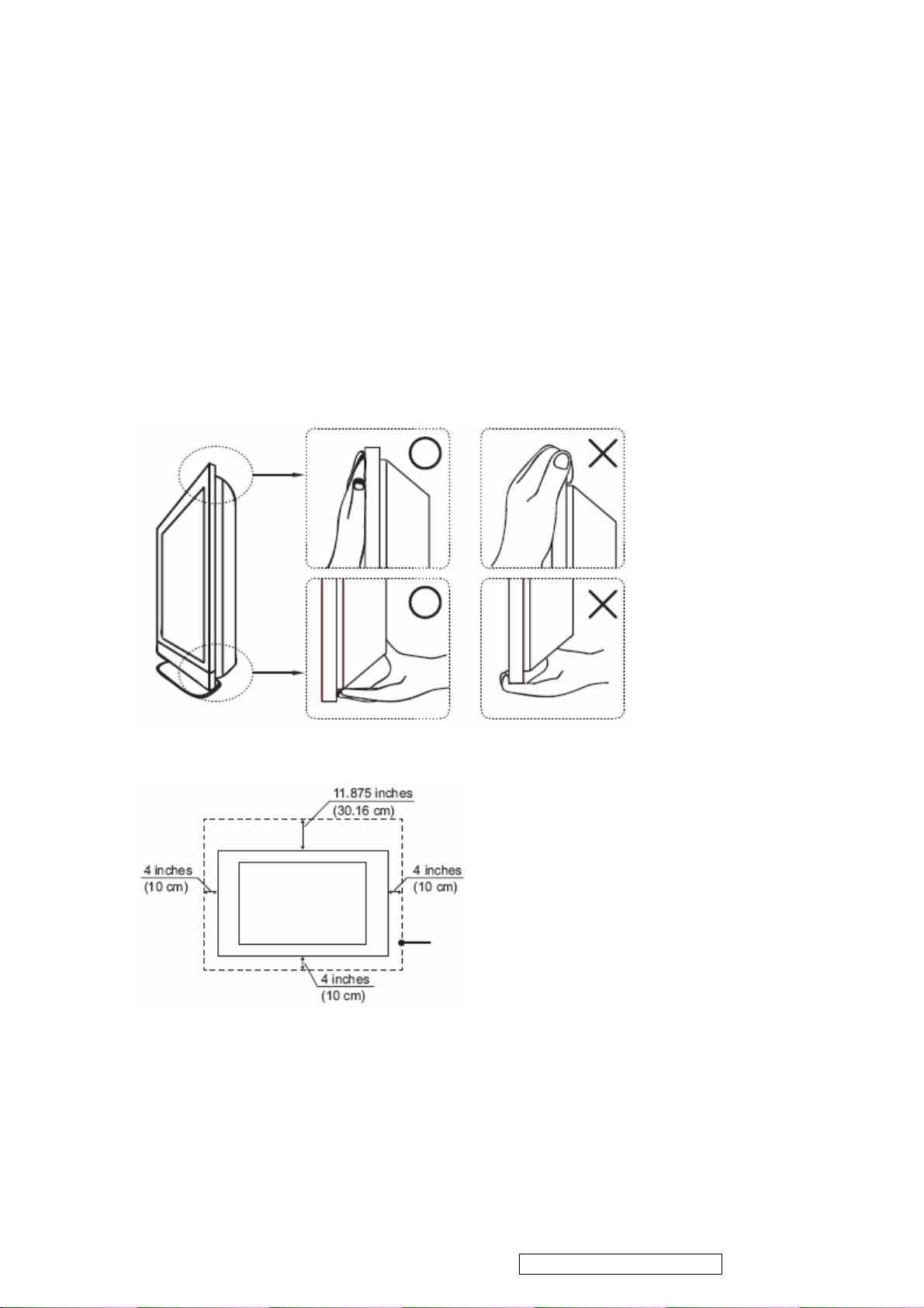
Carrying The TV
To prevent dropping the TV and causing serious injury, you must follow these
guidelines:
Disconnect all cables before carrying the TV.
Carrying the large size TV requires at least two or three people.
When you carry the TV, place your hands as illustrated and hold it securely.
Do not put stress on the LCD panel and the frame around the screen.
When carrying the TV, do not subject it to shocks, vibration, or excessive force.
When lifting or moving the TV, hold it securely from the bottom. Place your palm
directly under the panel.
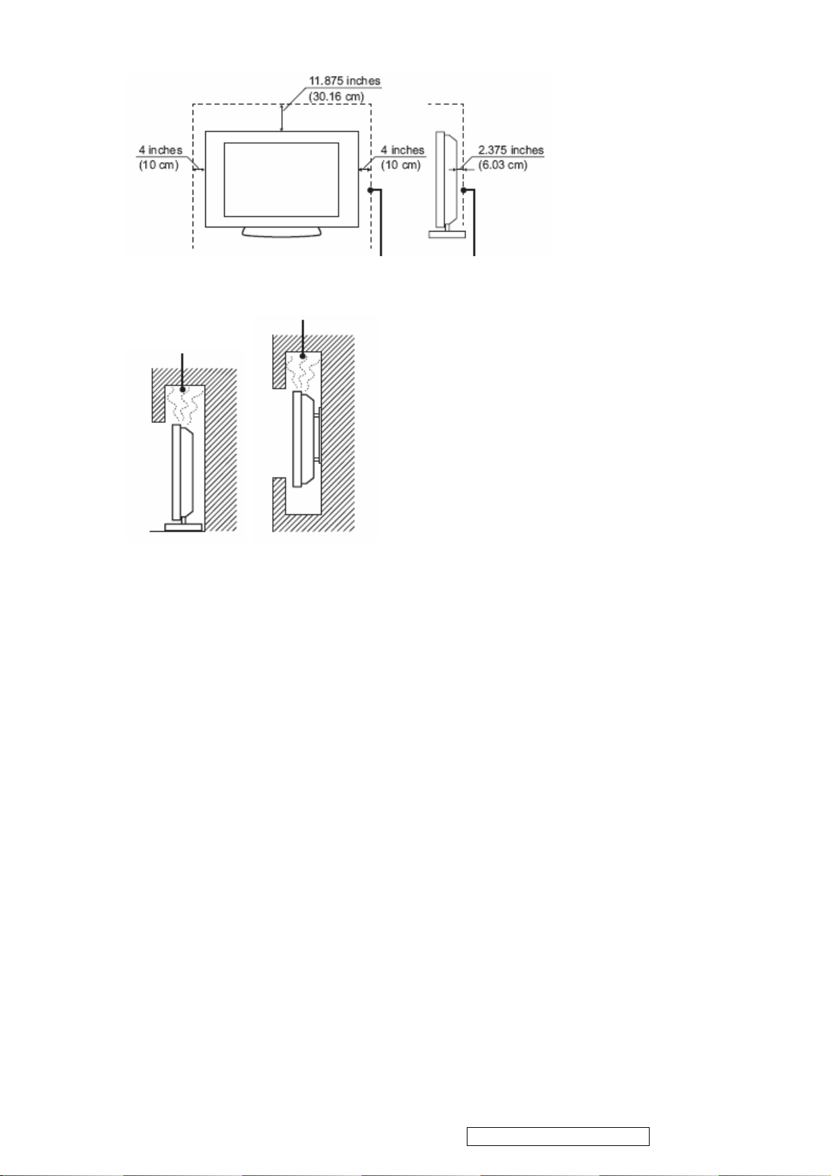
Installed on the wall
Installed with stand
ViewSonic Corporation Confidential - Do Not Copy VT2645-M
Page 6
5
Leave at least this space around the set. Do not install the TV set as follows:
Air circulation is blocked.
Broken pieces
Do not throw anything at the TV.
Doing so may break the screen glass and cause serious injury.
If the surface of the TV cracks, unplug the AC power cord before touching the TV.
Otherwise electric shock may result.
Handling of broken glass and liquid crystal leakage
If the LCD panel gets damaged, crystalline liquid leakage may occur, or scattered
broken glass may result.
Do not touch broken glass or crystalline liquid which is toxic, with bare hands as cuts,
poisoning or skin irritation may occur.
Also do not glass fragments or leaked crystalline liquid get into your eyes or mouth.
Should either contacted your eyes or mouth, rinse the contacted area thoroughly with
water and consult your doctor.
Note
This television includes a QAM demodulator, which should allow you to receive
unscrambled digital cable television programming via subscription service to a cable
service provider.
The type of programming and signal provided by your cable service provider will affect
the availability of digital cable television programming in your area.
ViewSonic Corporation Confidential - Do Not Copy VT2645-M
Page 7
6
2. Product Specification
2.1 Specification
Dimensions (with stand)
Physical(W)x(H)x(D)
Weight 7.3 kg
LCD 26” TFT Active Matrix RGB
Pixel Pitch 0.1405 (H) x 0.4215 (V) mm
Native Resolution 1366 x 768
Display area 575.769mm (H) x 323.712mm (V)
Speaker Output 5W x 2
Warning: Do not set the graphics card in your computer to exceed these refresh rates; doing
so may result in permanent damage to the LCD TV.
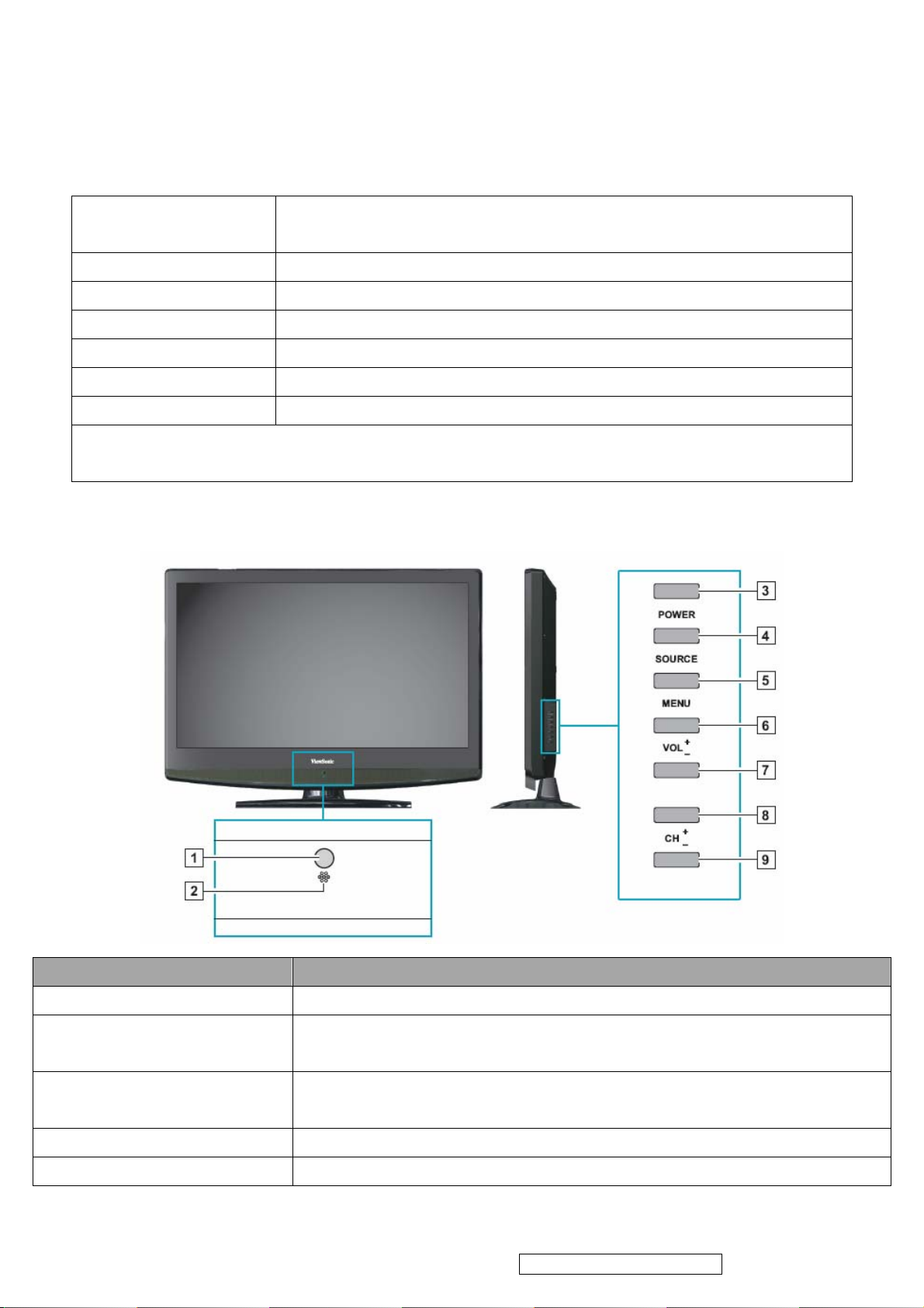
2.2 Front View
657.7mm x 506.5mm x 220mm
Item Description
1 Remote Control Receiver Receives IR signals from the remote control.
2 Power LED Indicator Lights up in blue when the TV is turned on. Lights up in orange when the TV
is in standby mode.
3 Power ON/OFF button Turn the power on from standby mode or turn the power off to return to the
standby mode.
4 SOURCE Select input source.
5 MENU Turn OSD menu ON/OFF.
ViewSonic Corporation Confidential - Do Not Copy VT2645-M
Page 8
6 Volume Up Increase sound volume or select a control while in OSD menu.
7
7 Volume Down Decrease sound volume or or select a control while in OSD menu.
8 CH Up Channel up when source is TV, or adjust a highlighted control while in OSD
menu.
9 CH Down Channel down when source is TV, or adjust a highlighted control while in
OSD menu.
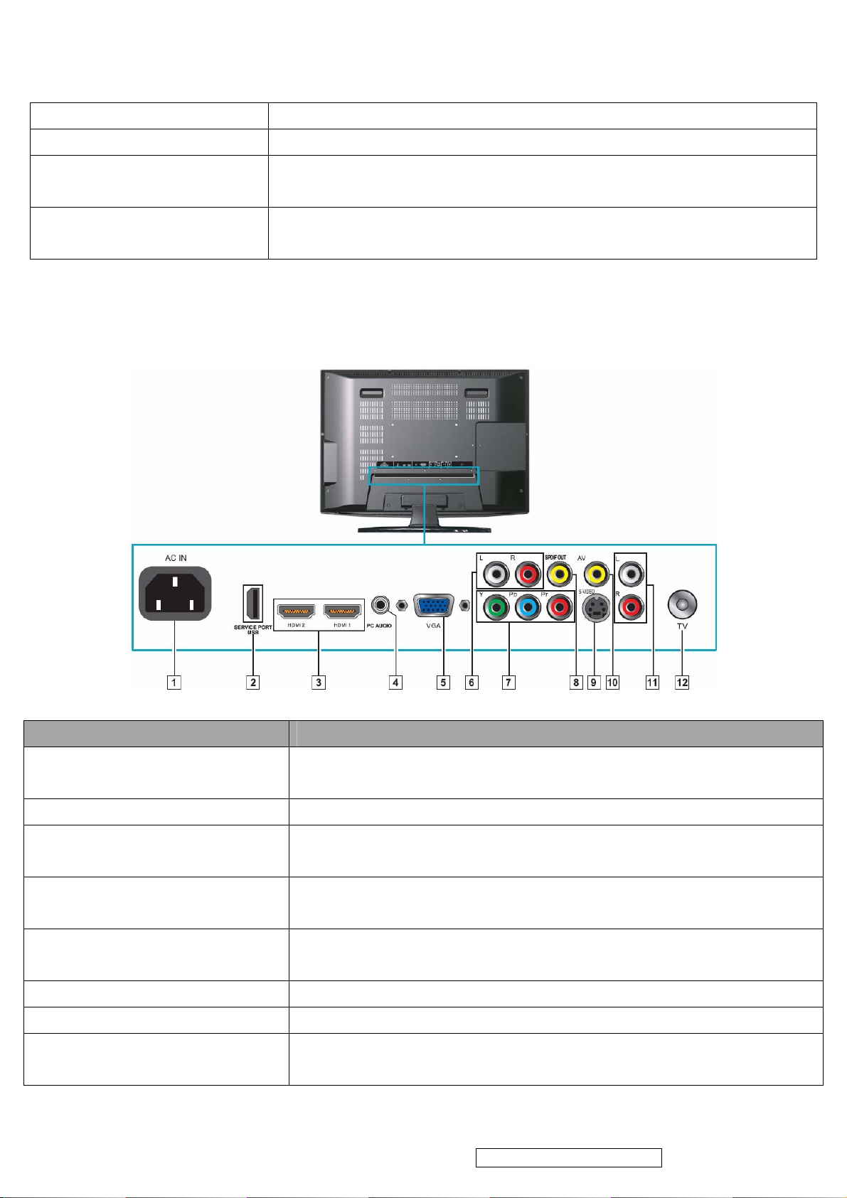
2.3 Rear View
Item Description
1 Power (AC input) Plug-in the supplied AC Power cord and connect to the AC input power
source (110~120V).
2 USB Service Port Service only. Not available for users.
3 HDMI 1 / 2 Connect this port to the HDMI/HDMI-DVI jack of the compatible equipment.
*If you use HDMI-DVI connections, please use PC Audio In for audio input.
4 PC Audio In Connect the PC Audio Out on your computer to the PC Audio In on the rear
of the LCD TV.
5 VGA Signal Input Connect a 15-pin D-sub RGB cable to the RGB output of your computer
and the other end to the RGB input on the rear of the LCD TV.
6 R/L Audio Inputs (YPbPr) Connect to an external device, such as a VCR, STB, or a DVD player.
7 YPbPr Connect to an external device, such as a VCR, STB, or a DVD player.
8 Coaxial Connect to a digital audio receiver supporting the S/PDIF standard, such as
a home theater receiver.
ViewSonic Corporation Confidential - Do Not Copy VT2645-M
Page 9
9 S-Video Input Connect to an external device, such as a VCR, STB, or a DVD player.
8
10 AV Connect to an external device, such as a VCR, STB, or a DVD player.
11 R/L Audio Input (AV/S-Video) Connect to an external device, such as a VCR, STB, or a DVD player.
12 TV Cable/Antenna Connect to a cable or antenna TV.
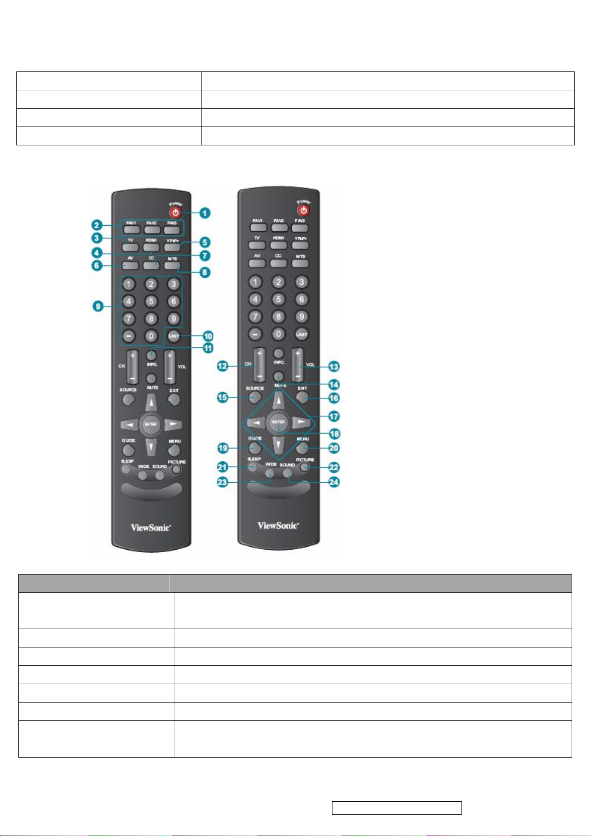
2.4 Remote Control
Button Description
1 POWER Press this button to turn the power on from standby mode. Press it again to
return to the standby mode.
2 FAV 1-3 Press to select favorite channels
3 TV Press to direct to TV source when in any other source.
4 HDMI Press to select source to HDMI or VGA mode.
5 YPbPr Press to select source to YPbPr mode.
6 AV Press to select source to AV or S-Video mode.
7 CC Press to turn Closed Caption On/Off
8 MTS Press to activate Multichannel Television Sound, Stereo or Mono.
ViewSonic Corporation Confidential - Do Not Copy VT2645-M
Page 10
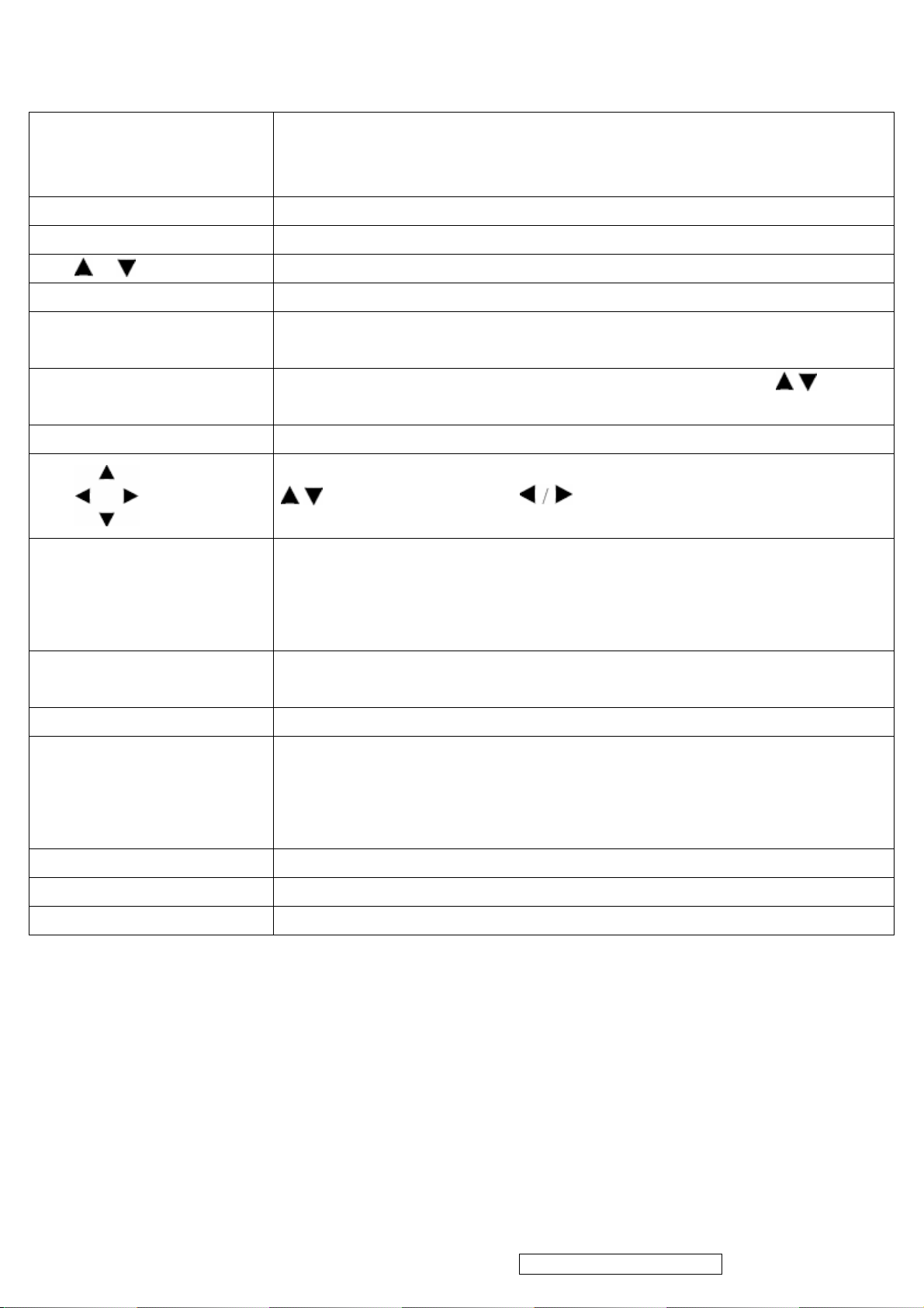
9 0~9, - number buttons Press 0~9 and “-” to select a channel.
9
After you input the channel numbers, press ENTER button to direct to the
channel immediately, or wait for 3 seconds to change automatically.
10 LAST Press to return to previous channel.
11 INFO Press this button to display the current state of the LCD TV.
12 CH
13 +VOL- Press to adjust the volume.
14 MUTE Press to turn off the sound. To restore the sound, press this button again, or
15 SOURCE
16 EXIT Press the button to exit the present menu.
17
18 ENTER Press to confirm the selection in the OSD menu, or to enter the OSD menu you
19 GUIDE Press to display the Electronic Program Guide (EPG).
Press to change the channels up or down.
press the VOL+ / VOL- button.
Press to display the INPUT source list and select the source with
To confirm the selection, press ENTER.
Press these buttons to navigate the OSD menus.
/ is for function select, and is for function adjustment.
select.
Pressing ENTER after you input channel numbers will change channels
immediately.
It contains the program information for the channel you’re watching.
/ buttons.
20 MENU Press to turn the OSD (On-Screen Display) menu on.
21 SLEEP Press repeatedly to set the off timer.
The function is used to automatically shut off the LCD TV after a preset period of
time passed. There are several times for choice – Off, 15 Min, 30 Min, 45 Min, 60
Min, 75 Min, 90 Min, 105 Min, and 120 Min.
22 PICTURE Press to adjust Picture mode.
23 WIDE Press to select Video Display format.
24 SOUND Press to adjust Sound mode.
ViewSonic Corporation Confidential - Do Not Copy VT2645-M
Page 11
10
3. Function Description
3.1 Using the OSD Menu
3.1.1 Press POWER to to turn the LCD TV on.
3.1.2 Press MENU on the remote control to display the Main menu.
3.1.3 Use
3.1.4 Use
setting.
3.1.5 Press ENTER to enter next OSD layer, use to change the setting, then
press ENTER to confirm.
to highlight an OSD Menu and press ENTER to enter the OSD Menu.
to highlight an individual OSD option, then use to change the
3.1.6 Press MENU to exit the menu.
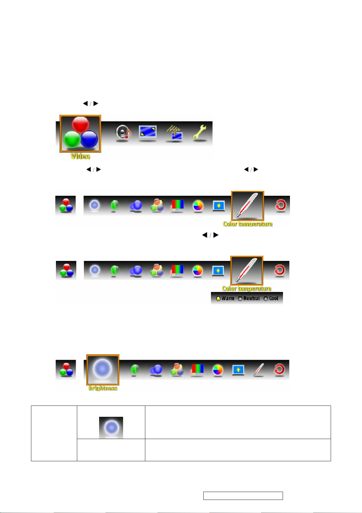
3.2 OSD Settings
3.2.1Video Settings
Brightness
Contrast Controls the difference between the brightest and darkest
Controls the overall brightness of the picture.
regions of the picture.
ViewSonic Corporation Confidential - Do Not Copy VT2645-M
Page 12
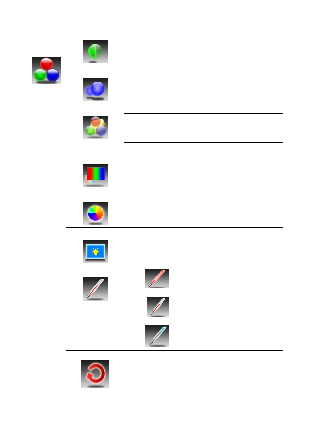
11
Video
Sharpness
Picture Mode
Color
Tint
Increase this setting to see crisp edges in the picture;
decrease it for soft edges.
Show room
Movie
Game
Sports
Custom
Controls the overall color of the picture.
Controls the difference between the green and red regions of
the picture.
Backlight
Color Temperature
Memory Recall
Dark Room
Medium Room
Bright Room.
Warm
Cool
Neutral
Resets all settings of Video.
ViewSonic Corporation Confidential - Do Not Copy VT2645-M
Page 13
12
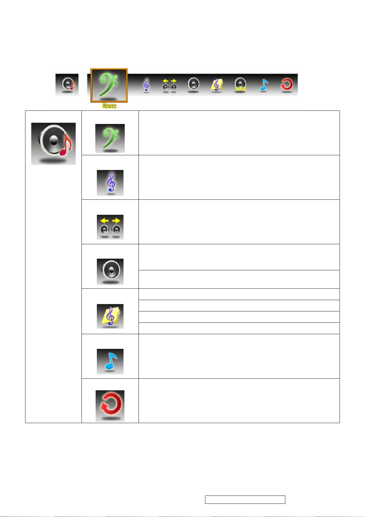
3.2.2 Audio Settings
Audio
Bass
Controls the relative intensity of lower-pitched sounds.
Treble
Balance
Audio mode
Controls the relative intensity of higher pitched sounds.
Adjusts the relative volume of the speakers in a multiple speaker
system.
OFF TV Speaker
ON
Rock
POP
Classical
Flat
Audio Only
Memory Recall
Turns off video and gives out audio only. Press any key to show
video.
Resets all settings of Audio.
ViewSonic Corporation Confidential - Do Not Copy VT2645-M
Page 14
13
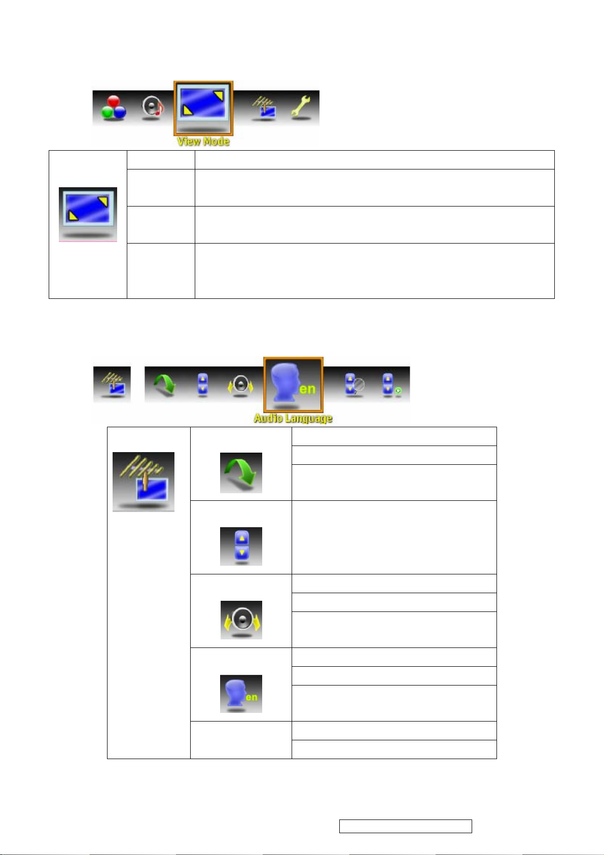
3.2.3 Screen Settings
No Scale Displays the 1:1 size of the original content.
View Mode
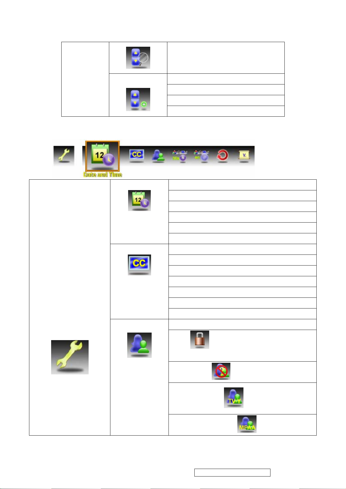
3.2.4 TV Program Settings
Normal Keeps the source display ratio. If the original input content is 4:3, then
shows 4:3. If the original input content is 16:9, then shows 16:9.
Full Enlarges the standard 4:3 source video to the 16:9 full screen video.
Overscan Enlarges the original picture horizontally and vertically to an equal
TV Program
When the source video is 16:9 in ratio, no change will occur.
aspect ratio that fills the screen. The redundant part of the upper,
bottom, left and right of the image will be removed.
Channel skip
Channel Skip List
Clear List
Channel Edit
Audio Language
Auto Scan
MTS
Channel Name Edit
Channel Name Edit
Allows you to assign a name to a
channel.
Mono
Mono
SAP
English
French
Spanish
Cable
Air
ViewSonic Corporation Confidential - Do Not Copy VT2645-M
Page 15
14
3.2.5 Setup Settings
Setup Settings
Manual Add
Date and Time
Closed Captions
Parental Control
Channel Add
Enter
Add
Cancel
Date. Allows the user to set the current time
Day of Week
Time Zone
Current Time
Adjust for Daylight Saving Time
Auto Calibration
Closed Captions
Analog Type
Digital Type
Font
Size
Font Color
Background Color
Enter Password
Rating Select ON/OFF to
activate/deactivate the Rating programs.
Block Unrated
TV-Y (TV Rating)
MPAA (MPAA Rating)
ViewSonic Corporation Confidential - Do Not Copy VT2645-M
Page 16
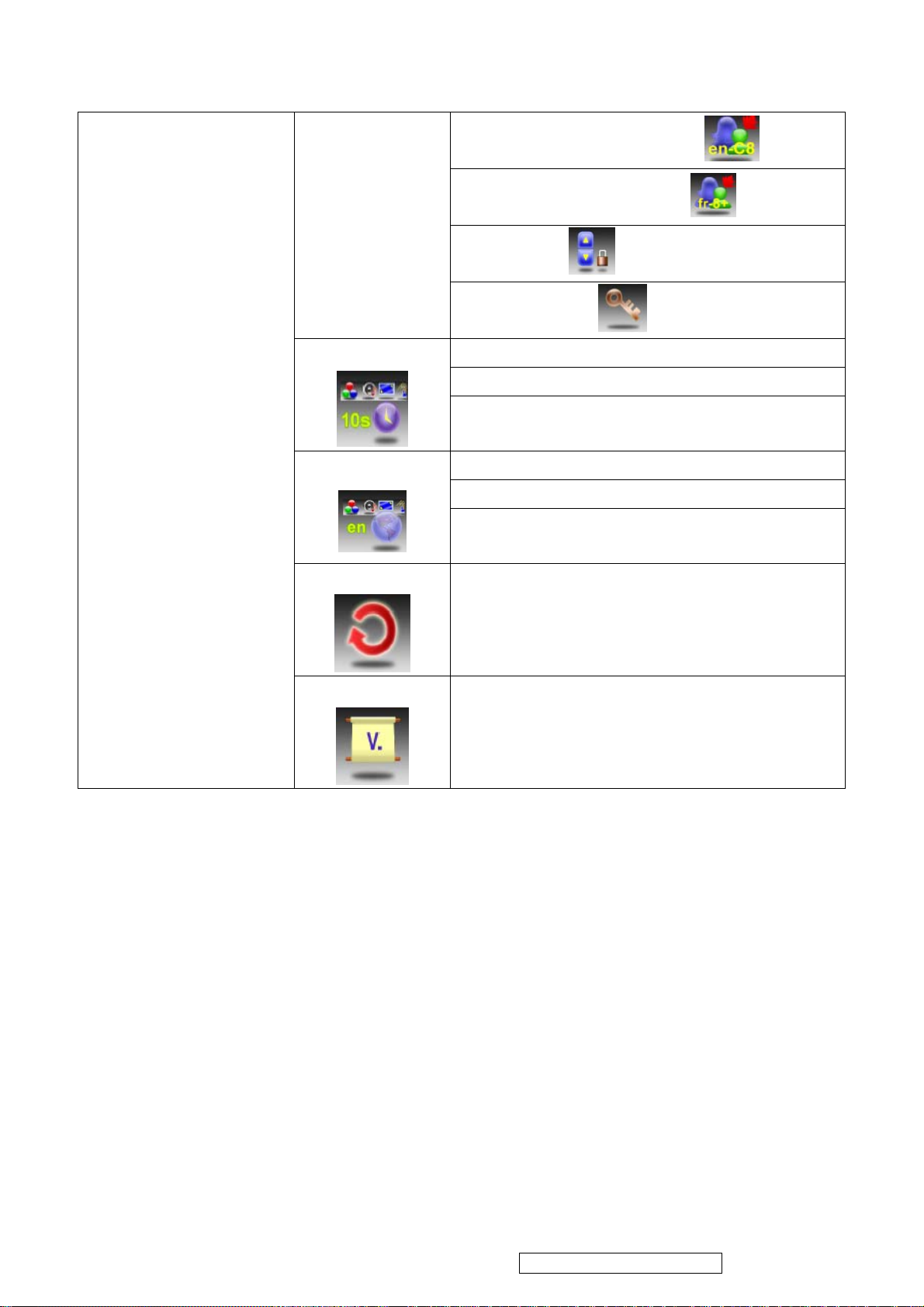
OSD Timeout
15
OSD Language
en-C8 (Canada English Rating)
fr-8+ (Canada French Rating)
Channel Block
Change Password
10 sec
20 sec
30 sec
English
French
Spanish
Reset All
Version
3.2.6 How to get into the factory mode and Hospitality mode
Press ENTER to reset all settings and restore
defaults.
Press ENTER to view the current TV version.
Factory model: Enter OSD "Setting" -> "Version" -> press arrow UP + "-" + ENTER+ENTER
Carnival (Hospitality) model: Pressing "Menu" and then "9876" key.
ViewSonic Corporation Confidential - Do Not Copy VT2645-M
Page 17
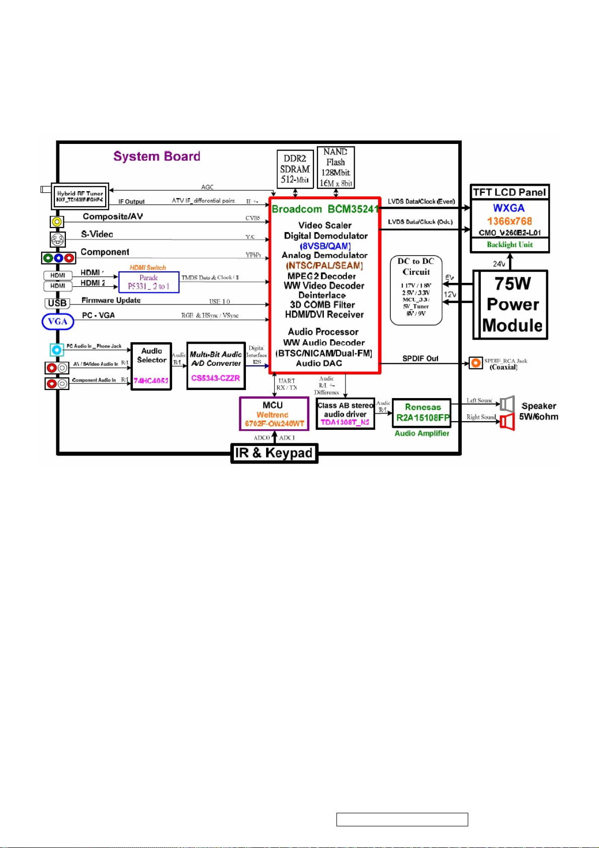
16
4. Block Diagram
ViewSonic Corporation Confidential - Do Not Copy VT2645-M
Page 18
17
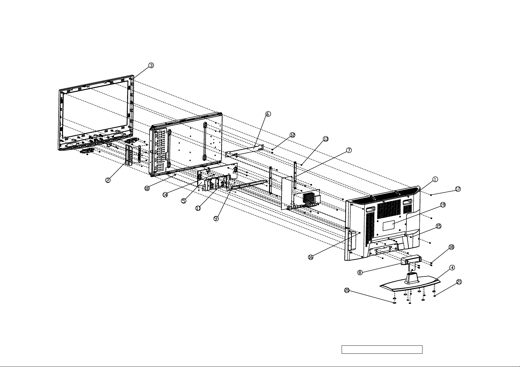
5. Exploded Diagram and Exploded Parts List
ViewSonic Corporation Confidential - Do Not Copy VT2645-M
Page 19
EXPLODED PARTS LIST ( VT2645-M )
18
ViewSonic Model Number: VS12675
Rev: 1A
Item ViewSonic P/N Ref. P/N Description Q'ty
1
2 NA 13EB-11B0211 EB11 26 BUTTON BEZEL MO 1
3
4 C-00009761 13EB-11Q0301 EB11 26 STAND BASE 1
5
6 HW-00008939 13EB-0EN0201 B17 26 BRACKET1 R1.0 1
7 HW-00008940 13EB-0EN0411 EB0E 26 BRACKET2 R1.1 2
8 C-00009760 13EB-0EQ0711 EB0E 26 BASE SUPPORT R1.1 1
9
10 HW-00008943 131C-006B000 SCREW M3*8L*9D (X) W-NI #2 6
11
12
13
14
15
16
17
18
19 NA 13EB-0EL0223 EB0E 26 REAR LABEL 1
20
21
C-00009759
C-00009758
HW-00008942
HW-00008941
HW-00008944
HW-00008946
HW-00008947
HW-00008948
HW-00008949
HW-00008950
HW-00008951
HW-00008952
M-00008405
M-00008406
13EB-07B0201 B09 26 REAR COVER MO 1
13EB-11B0101 EB11 26 FRONT COVER MO 1
13EB-0EN0111 EB0E 26 CHASSIS R1.1 1
13EB-0EN0501 B17 26 TERMINAL BRACKET R1.0 1
131C-0040000 SCREW M3*8L (B) B-NI 15
131A-006C000 SCREW M4*6(K) W-NI #2 9
131A-007C000 SCREW M3*6L (WS) W-ZN 14
131A-007G000 SCREW M4*6L (W) W-NI 1
131A-0082000 SCREW M3*8L (X) B-NI 7
131C-001G000 SCREW M3*10L (B) B-NI #2 8
131C-003U000 SCREW M3*14L (B) B-NI #2 4
131A-000P000 SCREW M4*15L (W) B-NI #2 4
13EB-03U0201 B05 RUBBER FOOT D=12.1 4
13EB-03U0301 B05 RUBBER FOOT D=20.6 6
ViewSonic Corporation Confidential - Do Not Copy VT2645-M
Page 20
3
19
Power Cable
8
Remote control with batteries
5
User Guide
6
7
4
9
1
2
10
11
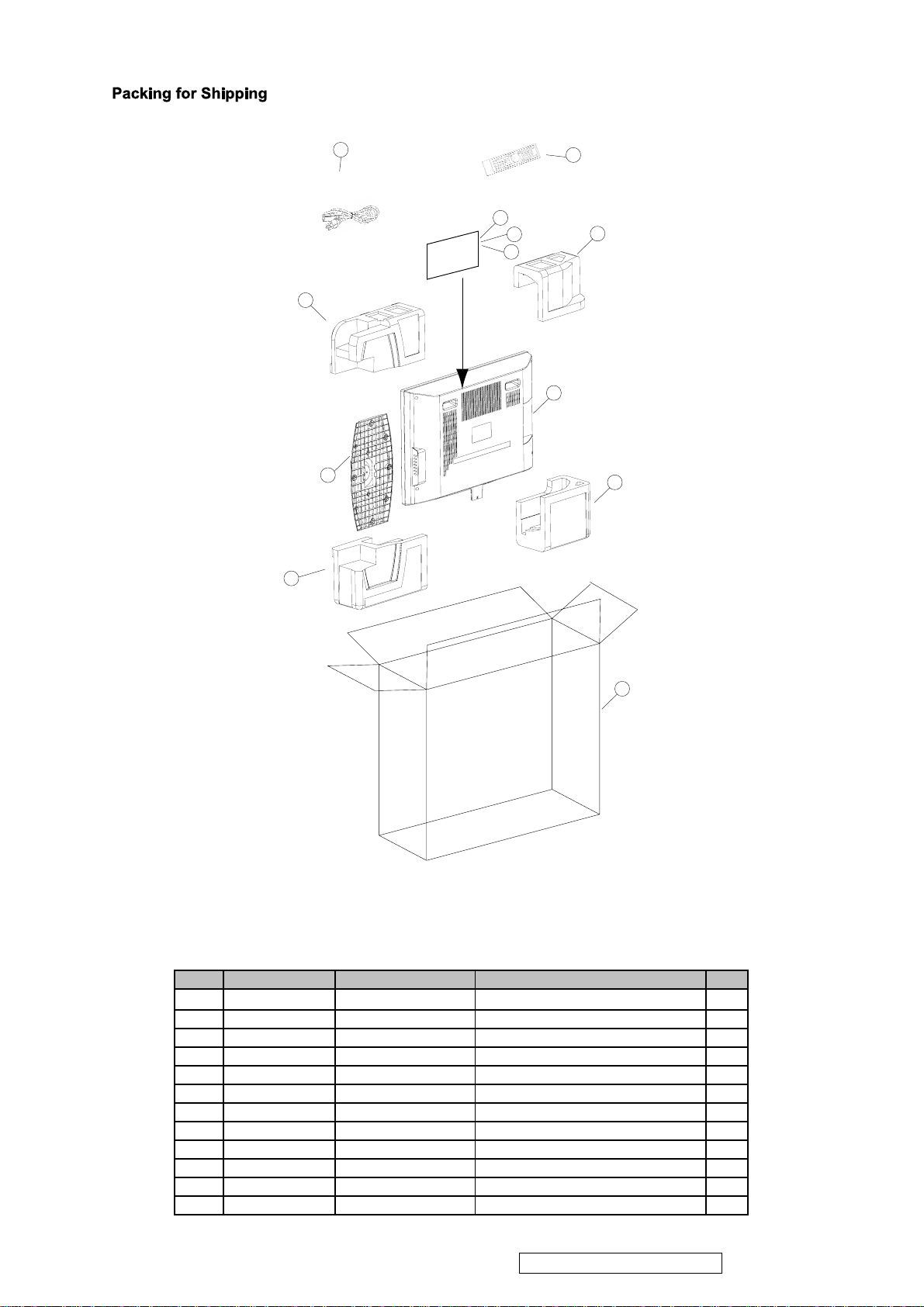
12
PACKING PART LIST ( VT2645-M )
ViewSonic Model Number: VS12675
Rev:
Item ViewSonic P/N Ref. P/N Description Q'ty
1TV1
2 STAND 1
3 Power Cable 1
4 Remote control 1
5
DC-00009821
6
DC-00009822
7 NA 1506-0B5D000 User Guide 1
P-00009734
8
P-00009735
9
10 P-00009736 1505-00YD000 EPS CUSHION VT3745-M(BR) 1
11
P-00009737
12 NA 1503-024V000 CARTON 1
1506-09L9000 Quick Start Guide BAG 1
1506-09UF000 Quick Start Guide 1
1505-00YB000 EPS CUSHION VT3745-M(TR) 1
1505-00YC000 EPS CUSHION VT3745-M(TL) 1
1505-00YE000 EPS CUSHION VT3745-M(BL) 1
ViewSonic Corporation Confidential - Do Not Copy VT2645-M
Page 21

20
6. Disassembly Procedure
Please follow the information provided in this section to perform the complete
disassembly procedure of the LCD panel. Be sure to use proper tools described
below.
LCD consists of various Parts. This chapter describes the procedures for the
complete parts disassembly. In addition, in between procedures, the detailed
disassembly procedure of individual parts will be provided for your service needs.
The disassembly procedure consists of the following steps:
Base
Rear Cover
Bracket
Keypad
Cable
Mainboard
PSU
IR Board
Speaker
Panel
Base
1. Remove 4 screws (M4*15L W) that fixing the base with the rear cover.
ViewSonic Corporation Confidential - Do Not Copy VT2645-M
Page 22

2. Remove screw (M4*10L S) to take the base module apart.
21
BASE SUPPORT
BASE
Rear Cover
1. Remove 2 screws (M3*10L B) and 5 screws (M3*8L X) that fixing on the rear cover.
ViewSonic Corporation Confidential - Do Not Copy VT2645-M
Page 23

2. Remove 4 screws (M3*10L B) that fixing on the rear cover.
22
3. Remove 4 screws (M3*14L B) that fixing on the rear cover.
ViewSonic Corporation Confidential - Do Not Copy VT2645-M
Page 24

23
4. Remove the rear cover.
Bracket
1. Remove 2 screws (M3*10L B), 2 screws (M3*8L X) and 4 screws (M3*8L B) that
fixing on the I/O bracket.
ViewSonic Corporation Confidential - Do Not Copy VT2645-M
Page 25

2. Remove 2 screws (M3*6L WS) that fixing the I/O bracket with the panel.
24
3. Remove 4 screws (M3*6L WS) that fixing the left and right bracket cable clamps.
4. Remove 7 screws (M4*6 K) that fixing the bracket and chassis.
ViewSonic Corporation Confidential - Do Not Copy VT2645-M
Page 26

5. Remove 4 screws (M3*8L) that fixing on the chassis.
25
6. Remove 2 screws (M4*8LX) that fixing the chassis with the panel.
7. Remove the chassis.
Keypad
1. Remove 2 screws (M3*8L B) that fixing the keypad module with front cover module.
ViewSonic Corporation Confidential - Do Not Copy VT2645-M
Page 27

26
2. Disconnect IR-Keypad wire from keypad.
3. Remove 3 screws (M3*8L B) to take the keypad module apart.
ViewSonic Corporation Confidential - Do Not Copy VT2645-M
Page 28

27
4. Disconnect Keypad-MB wire from Keypad.
Cable
1. Disconnect Keypad-MB wire from mainboard.
2. Disconnect the PSU-MB cable.
ViewSonic Corporation Confidential - Do Not Copy VT2645-M
Page 29

28
3. Disconnect speaker cable
4. Disconnect the LVDS cable from panel.
5. Open the cover of the LVDS connector on the Mainboard.
6. Insert the LVDS cable.
ViewSonic Corporation Confidential - Do Not Copy VT2645-M
Page 30

29
7. Close the cover of the LVDS connector.
Mainboard
Remove 4 screws (M3*6L WS) that fixing on the Mainboard.
PSU
1. Remove screw (M4*6L W) that fixing the grounding wire with panel.
ViewSonic Corporation Confidential - Do Not Copy VT2645-M
Page 31

30
2. Disconnect cables from PSU
3. Remove 4 screws (M3*6L WS) that fixing the PSU.
ViewSonic Corporation Confidential - Do Not Copy VT2645-M
Page 32

31
IR Board
1. Disconnect the IR wire from IR board.
2. Remove 2 screws (M3*8L B) that fixing the IR board.
Speaker
Remove 4 screws (M3*8L*9D) that fixing the speakers on front cover.
ViewSonic Corporation Confidential - Do Not Copy VT2645-M
Page 33

32
Panel
1. Remove 2screws (M3*8L*9D X) that fixing the panel
2. Remove the panel from front cover.
ViewSonic Corporation Confidential - Do Not Copy VT2645-M
Page 34

33
Recommended Spare Parts List
7.
ViewSonic Model Number: VS12675
RECOMMENDED SPARE PARTS LIST (VT2645-M)
Rev:1a
Serial No. Prefix: REG
Item Category Part Name Description ECR/ECN ViewSonic P/N Ref. P/N Ref. NO Compatibility Location Universal number#
1 Remote Controlle
Accessories: [Adapter,
2 Power Cor
Remote Controller, Power
3 Batter
, External Cables]
Cord
4 Main Board VT2645-M MAIN BD./VS
PC Board Assembly: [All
5
PCBA]
6
7 Button Bezel EB11 26 BUTTON BEZEL MO
Cabinets:
8 Front Cove
[Front Bezel, All Covers,
9 Back Cove
Base Assembly]
10
11
12 Flat Cable FFC CABLE 30P P:1.0mm L:230mm
Cables: [All internal
13 wire POWER CABLE 13P TO 15P L:180m
Cables/wires]
14 wire POWER CABLE 7P TO 14P L:100mm
15 wire W.H CABLE 8P TO 8P,L:530mm
16 wire W.H CABLE 8P TO 8P,L:530mm
17 wire W.H CABLE 5P TO 5P,L:430mm
18 wire W.H CABLE 5P TO 5P,L:430mm
19
Documentation: [Quick
20
Start Guide, CD Rom;
21 User's Guide (CD ROM) UM ML VIEW SONIC
Label]
22
23
24
25
26
27
Electronic
28
Components:[LCD TV
29
Panel, Speaker]
30
31
32 Bracke
Hardware: [Screw,
33 Bracke
Bracket, Hinge]
34 Bracke
35 CHASSIS EB0E 26 CHASSIS R1.1
36 Screw SCREW M3*8L*9D (X) W-NI #2
37 Screw SCREW M3*8L (B) B-NI
38 Screw SCREW M4*8L(X) B-NI
39 Screw SCREW M4*6(K) W-NI #2
40 Screw SCREW M3*6L (WS) W-ZN
41 Screw SCREW M4*6L (W) W-NI
42 Screw SCREW M3*8L (X) B-NI
43 Screw SCREW M3*10L (B) B-NI #2
44 Screw SCREW M3*14L (B) B-NI #2
45 Screw SCREW M4*15L (W) B-NI #2
46 clip B17 BRACKET1 CABLE CLAMP
Miscellaneous: [Switch,
47 clip B17 BRACKET2 CABLE CLAMP
Fan, Rubber Foot, Logo]
48
49
50
51
52 Carton CARTON VT2645-M
Packing Material: [Box,
53 Cushion EPS CUSHION VT2645-M (TR)
Foam, Bags]
54 Cushion EPS CUSHION VT2645-M (TL)
55 Cushion EPS CUSHION VT2645-M (BR)
56 Cushion EPS CUSHION VT2645-M (BL)
57 Plastic Bag PET COVER EQ2688
58 Plastic Bag PE BAG STAND WDE-US-26F
59 Plastic Bag EPE BAG WDE-US-26
60 Plastic Bag ZIP BAG FOR VIEWSONIC
Ke
y Pad
IR Boar
Base Assembl
Stand Assembl
Qucik Start Guide
Qucik Start Guide
Label / Sticke
Label / Sticke
Label / Sticke
Label / Sticke
Label / Sticke
Panel
Panel
S
peaker
Power Su
Power Su
Foo
t
Foo
t
Foo
t
Ta
pe
Above listed items are examples, supplier can expand the rows to add more necessary items.
Remark 1:
Remark 2:
All revised RSPLs with newly added items or any change made should be highlighted and correlated with the ECN/ECR approved by ViewSonic Corporation. This is to eliminate repeated cross checks of
Notice: 1. For some special parts, some photos for identification purpose may be asked by reques
2. For all internal cables, there must be some wordings on the "Description" column about where the cable is used (connecting to which two parts)
3. All internal cables/wires should be put in the "Cables" categor
4. All external cables should be put in the "Accessories" category
5. Parts relationship (Main/Second source or 1/2/3/4) should be added in the "Compatibility" column
6. If any part for certain product isn't listed in the form, supplier/PE can add it themselves and keep the part name unified.
r REMOTE CONTROL VIEWSONIC
d AC POW.CORD UL/CSA/3P/3C,BLK
y R03P UM-4 AAA BATTERY
VT2645-M KEYPAD BD./VS
d
r EB11 26 FRONT COVER MO
r B09 26 REAR COVER MO
y
y
r
r
r
r
r
pply
pply
t B17 26 BRACKET1 R1.0
t EB0E 26 BRACKET2 R1.1
t B17 26 TERMINAL BRACKET R1.0
VT3745-M IR BD./VS
EB0E 26 BASE SUPPORT R1.1
EB11 26 STAND BASE
QUICK START GUIDE ENG VT2645-M
(QSG)
QUICK START GUIDE FRA VT2645-M
(QSG)
EB0E 26 REAR LABLE
SERIAL LABEL VIEWSONIC
ENERGY STAR LABEL 11*11mm R1.0
RATING LABEL VT2645-M
UPC LABEL VT2645-M
LCD TFT 26.0' WXGA HD 4U-CCFL
LCD TFT 26.0' WXGA HD 4U-CCFL
SPEAKER WDE26F 5W 120X25X30mm
POWER OPENFRAME 75W/+5,12,24V
POWER OPENFRAME 75W/+5,12,24V
B05 RUBBER FOOT D=12.1
B05 RUBBER FOOT D=20.6
LAYER PAD EQ2688
TAPE
y
A-00008537
A-00008538
A-00008539
B-00009808
B-00009809
B-00009810
C-00009757
C-00009758
C-00009759
C-00009760
C-00009761
t
CB-00009126
CB-00009127
CB-00009128
CB-00009129
CB-00009130
CB-00009131
CB-00009132
DC-00009821
DC-00009822
DC-00009823
DC-00009824
DC-00009825
DC-00009826
DC-00009827
DC-00009828
E-00009606
E-00009607
E-00009608
E-00009609
E-00009610
HW-00008939
HW-00008940
HW-00008941
HW-00008942
HW-00008943
HW-00008944
HW-00008945
HW-00008946
HW-00008947
HW-00008948
HW-00008949
HW-00008950
HW-00008951
HW-00008952
M-00008403
M-00008404
M-00008405
M-00008406
M-00008407
M-00008408
P-00009733
P-00009734
P-00009735
P-00009736
P-00009737
P-00009738
P-00009739
P-00009740
P-00009365
m
04AD-007W0VO
1411-0018000
0B09-0007000
69EB2UM10A01P
69EB2UK10A01P
69EB2VR10A01P
13EB-11B0201
13EB-11B0101
13EB-07B0201
13EB-0EQ0711
13EB-11Q0301
1412-00E7000 M
1414-016D000 M
1414-01SB000 M
1414-01GJ000 M
1414-016Q000 S
1414-01GK000 M
1414-016P000 S
1506-09L9000 M
1506-09UF000 M
1506-09L6000 M
13EB-0EL0203 M
1510-0AFG000 M
1510-01PK000 M
1510-0A4W000 M
1510-0AHK000 M
1823-00K70VO M
1823-00K7000 S
04A4-00DY000 M
0433-000H000 M
0433-000E000 S
13EB-0EN0201 M
13EB-0EN0411 M
13EB-0EN0501 M
13EB-0EN0111
131C-006B000 M
131C-0040000 M
131A-0088000 M
131A-006C000 M
131A-007C000 M
131A-007G000 M
131A-0082000 M
131C-001G000 M
131C-003U000 M
131A-000P000 M
13EB-0EQ0501 M
13EB-0EQ0601 M
13EB-03U0201 M
13EB-03U0301 M
1524-00K9000 M
13EB-0DU0A01 M
1503-01DE000 M
1505-00YB000 M
1505-00YC000 M
1505-00YD000 M
1505-00YE000 M
1516-00HU000 M
1516-00D5000 M
1516-007A000 M
1517-000Q000 M
M
M
M
M
M
M
M
M
M
M
M
M
ViewSonic Corporation Confidential - Do Not Copy VT2645-M
Page 35

34
8. BIOS /Firmware Update SOP
8.1 How to upgrade HDTV firmware
Step1: Prepare a USB flash disk, a PC and the target HDTV
`
Step2: Use PC to obtain FIRMWARE.PKG from WebService.
Put “FIRMWARE.PKG” file onto “C:\Temp”.
Step3: Plug USB flash disk to PC.
Select USB disk in “My Computer”.
Select “Properties” item below to see USB file system format.
ViewSonic Corporation Confidential - Do Not Copy VT2645-M
Page 36

Make sure FAT32 format in USB
35
Copy “C:\Temp\FIRMWARE.PKG” to the ROOT directory of USB disk.
ViewSonic Corporation Confidential - Do Not Copy VT2645-M
Page 37

36
Step4: Plug USB disk to HDTV
Un-plug USB disk from PC
Plug the USB disk to the HDTV (power off)
Step5: Power on HDTV
Power on HDTV.
It will show upgrading progresses automatically within 3 seconds.
The HDTV screen will show red and blue progress bar several times.
ViewSonic Corporation Confidential - Do Not Copy VT2645-M
Page 38

37
Step6: Power off automatically when finished
Remove the USB flash disk from HDTV.
8.2 How to format to FAT32
Plug USB flash disk to PC.
In “My Computer” folder, Select “Format…” function in the pop-up menu.
Select FAT32, then press “Start”.
ViewSonic Corporation Confidential - Do Not Copy VT2645-M
Page 39

38
8.3 Supported USB flash disks
SanDisk
Kingston
KingMax
8.4 RMA test procedure
Install factory tool
8.4.1 Install visa450runtime
8.4.2 Finish Install.
8.4.3 Connect the USB cable between PC and PWR meter
ViewSonic Corporation Confidential - Do Not Copy VT2645-M
Page 40

39
8.4.4 Restart the PC, the device can be found on the control panel.
8.4.5 Install the factory tool for repair.
ViewSonic Corporation Confidential - Do Not Copy VT2645-M
Page 41

Finish installing under installation guide.
40
8.4.6 Run the factory tool.
8.4.7 When Login every initial screen, it should key in the user name and ISN number.
Key in the job number、password, and log in.
ViewSonic Corporation Confidential - Do Not Copy VT2645-M
Page 42

Input serial number of TV.
41
8.4.8 Test1 station, Initialize
ViewSonic Corporation Confidential - Do Not Copy VT2645-M
Page 43

42
connect the USB to RS232 cable+RS232 cable on TV.
Connect the other end of the RS232 cable with PC.
ViewSonic Corporation Confidential - Do Not Copy VT2645-M
Page 44

43
Choose T1.
Press auto run.
Press “No” to go the Test 2 station.
ViewSonic Corporation Confidential - Do Not Copy VT2645-M
Page 45

8.4.9 Test 2 Station, Backlight and Gamma alignment.
44
Rear view of Color analyzer.
ViewSonic Corporation Confidential - Do Not Copy VT2645-M
Page 46

Choose T2.
45
Choose the type of color analyzer, then press”AUTO RUN”
If you do not need to test next one, press “No” to go to T3 station.
ViewSonic Corporation Confidential - Do Not Copy VT2645-M
Page 47

46
8.4.10 T3 station, Color temperature check.
ViewSonic Corporation Confidential - Do Not Copy VT2645-M
Page 48

47
Choose type of Color analyzer&Patterngenerator
Press ”AUTO RUN”
ViewSonic Corporation Confidential - Do Not Copy VT2645-M
Page 49

48
Check Gamma_6500
Check Gamma_9300
ViewSonic Corporation Confidential - Do Not Copy VT2645-M
Page 50

Check Gamma_11000
49
Turn off the power.
Check the power consumption should<1w
ViewSonic Corporation Confidential - Do Not Copy VT2645-M
Page 51

If not test the next one, press “No” to go to T4 station.
50
8.4.11 T4 Station, EDID writing
ViewSonic Corporation Confidential - Do Not Copy VT2645-M
Page 52

Go to the T4 station, press “Start”.
51
ViewSonic Corporation Confidential - Do Not Copy VT2645-M
Page 53

It will show “All pass” when the work finished.
52
8.4.12 T5, SN writing
ViewSonic Corporation Confidential - Do Not Copy VT2645-M
Page 54

53
ViewSonic Corporation Confidential - Do Not Copy VT2645-M
Page 55

Go to the T4 station, press ”Start”.
54
If the connection is all right, it will show green check mark.
Input the SN number of TV.
ViewSonic Corporation Confidential - Do Not Copy VT2645-M
Page 56

55
Press Enter, if it works normally will show ”All Pass”.
8.4.13 Check SN number
ViewSonic Corporation Confidential - Do Not Copy VT2645-M
Page 57

8.4.13.1 Check in OSD
56
Menu->Settings->Version
8.4.13.2 Check by Patten generator
Make sure to follow below process:
Turn on the TV.
Connect TV with Chromma22293 VGA and HDMI.
Switch TV source to VGA or HDMI
Set Chroma 22293
Timing:14 Pattern:701(VGA)
Timing:70 Pattern:701(HDMI)
ViewSonic Corporation Confidential - Do Not Copy VT2645-M
Page 58

57
9. Trouble Shooting Flow Chart
9.1 No Power
9.2 Can not start
ViewSonic Corporation Confidential - Do Not Copy VT2645-M
Page 59

9.3 No display
58
9.4 Abnormal display
ViewSonic Corporation Confidential - Do Not Copy VT2645-M
Page 60

9.5 No sound
59
ViewSonic Corporation Confidential - Do Not Copy VT2645-M
Page 61

60
9.6 Key Board
ViewSonic Corporation Confidential - Do Not Copy VT2645-M
Page 62

10. FAQ
61
Problem Solution
No power • Make sure the power cord is properly connected to the
LCD TV AC power socket.
• Make sure the AC power cord is properly connected to
the wall outlet.
• Make sure the DC power button is ON (Blue LED).
• Plug another electrical device (like a radio) to the power
outlet to verify that the outlet is supplying the proper
voltage.
No picture • The TV station may be experiencing problems. Try
another channel.
• The Cable TV signal may be scrambled or encoded.
Please contact your local cable operator.
• Make sure that connection to other components are
correct referring to the user guide.
• Make sure that setup has been done correctly after
connections.
• Make sure the correct input is selected and the input
signal is compatible.
Strange color, light color, or color
misalignment
Unit cannot be operated • External influences such as lightning or static electricity
No sound • Check your audio connections are properly connected
• Ensure that the video cable is securely connected.
• The picture may appear dim in a brightly lit room.
• Adjust brightness, contrast, saturation (color), and tint
referring to the user guide.
• Check the input signal setting.
may cause improper operation. In this case, operate the
unit after first turning on the power of the LCD TV and the
AVC System, or unplug the AC cord for 1 to 2 minutes,
then plug in again.
referring to the user guide.
• The MUTE button may have been pressed, try pressing
this button again.
• Check your audio settings, your TV audio may be set to
minimum.
• Press the Volume + (Up) button on the remote control.
Remote control unit does not operate • Make sure the directions of batteries are inserted
ViewSonic Corporation Confidential - Do Not Copy VT2645-M
Page 63

correctly referring to the user guide.
62
• Batteries could be weak or dead. Replace with new
batteries.
• Is a fluorescent light illuminated near the remote control
sensor?
• The path of the remote control beam may be blocked.
Make sure the path is clear and that the remote control is
aimed at the remote control sensor on the TV.
• Press the POWER button on the remote control to see if
you can turn on the TV.
• Press MENU button on the remote control to see if
there is a MENU shown on the screen.
• Press only one button at a time and it is the correct one
for the operation you want to perform.
Picture is cut off/with sidebar screen • Is the image positioned correctly?
• Are screen mode adjustments such as picture size set
correctly?
• Press WIDE button repeatedly on the remote control to
see if you can get the picture you prefer.
Power is cut off suddenly • Is the sleep timer set in advance?
• Is there no signal in PC mode or HDMI mode?
• The internal temperature of the unit has increased.
Remove any objects blocking the vent or clean as
necessary.
No CATV reception (or no reception
above CH13)
• Is the AIR/CABLE option set correctly?
Please set the AIR/CABLE option to CABLE referring to
the user guide.
• CATV is connected improperly or not connected; please
check all the CATV connections.
• The cable TV service is interrupted; please contact your
cable operator.
ViewSonic Corporation Confidential - Do Not Copy VT2645-M
Page 64

* Reader’s Response*
63
Dear Readers:
Thank you in advance for your feedback on our Service Manual, which allows continuous improvement
of our products. We would appreciate your completion of the Assessment Matrix below, for return to
ViewSonic Corporation.
Assessment
A. What do you think about the content of this Service Manual?
Unit Excellent Good Fair Bad
1. Precautions and Safety Notices
2. Product Specification
3. Function Description
4. Block Diagram
5. Exploded Diagram and Exploded Parts List
6. Disassembly Procedure
7. Recommended Spare Parts List
8. BIOS /Firmware Update SOP
9. Trouble Shooting Flow Chart
10. FAQ
B. Are you satisfied with this Service Manual?
Item Excellent Good Fair Bad
1. Service Manual Content
2. Service Manual Layout
3. The form and listing
C. Do you have any other opinions or suggestions regarding this service manual?
Reader’s basic dada:
Name: Title:
Company:
Add:
Tel: Fax:
E-mail:
After completing this form, please return it to ViewSonic Quality Assurance in the USA at facsimile
1-909-839-7943.
ViewSonic Corporation Confidential - Do Not Copy VT2645-M
 Loading...