

ViewSonic Q9b-2, VS11201 Service manual
Service Manual
ViewSonic Q9b-2
Model No. VS11201
19” Color TFT LCD Display
(Q9b-2_SM Rev. 1b Aug. 2006)
ViewSonic 381 Brea Canyon Road, Walnut, California 91789 USA – (800) 888-8583
Copyright
Copyright © 2006 by ViewSonic Corporation. All rights reserved. No part of this publication
may be reproduced, transmitted, transcribed, stored in a retrieval system, or translated into any
language or computer language, in any form or by any means, electronic, mechanical, magnetic,
optical, chemical, manual or otherwise, without the prior written permission of ViewSonic
Corporation.
Disclaimer
ViewSonic makes no representations or warranties, either expressed or implied, with respect to
the contents hereof and specifically disclaims any warranty of merchantability or fitness for any
particular purpose. Further, ViewSonic reserves the right to revise this publication and to make
changes from time to time in the contents hereof without obligation of ViewSonic to notify any
person of such revision or changes.
Trademarks
Optiquest is a registered trademark of ViewSonic Corporation.
ViewSonic is a registered trademark of ViewSonic Corporation.
All other trademarks used within this document are the property of their respective owners.
Revision History
Revision SM Editing Date ECR Number Description of Changes Editor
1a 05/02/2006 Initial Release Jamie Chang
1b 08/22/2006
VS-E060267 Add 2nd panel source(HSD190ME-A10/A16)
VS-E060268
(updated RSPL, BOM, Spec.)
Jamie Chang
ViewSonic Corporation Confidential - Do Not Copy Q9b-2
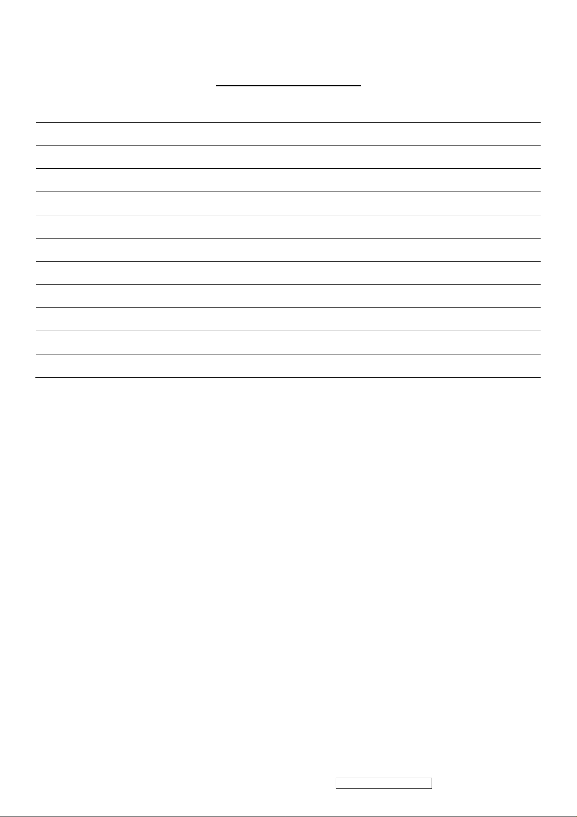
TABLE OF CONTENTS
1. Precautions and Safety Notices 1
2. Specification 5
3. Front Panel Function Control Description 14
4. Circuit Description 20
5. Adjustment Procedure 25
6. Troubleshooting Flow Chart 45
7. Recommended Spare Parts List 53
8. Exploded Diagram and Exploded Parts List 58
9. Block Diagram 61
10. Schematic Diagrams 62
11. PCB Layout Diagrams 69
ViewSonic Corporation Confidential - Do Not Copy Q9b-2

1. Precautions and Safety Notices
1. Appropriate Operation
(1) Turn off the product before cleaning.
(2) Use only a dry soft cloth when cleaning the LCD panel surface.
(3) Use a soft cloth soaked with mild detergent to clean the display housing.
(4) Use only a high quality, safety approved AC/DC power cord.
(5) Disconnect the power plug from the AC outlet if the product will not be used for a long period of time.
(6) If smoke, abnormal noise, or strange odor is present, immediately switch the LCD display off.
(7) Do not touch the LCD panel surface with sharp or hard objects.
(8) Do not place heavy objects on the LCD display, video cable, or power cord.
(9) Do not use abrasive cleaners, waxes or solvents for your cleaning.
(10) Do not operate the product under the following conditions:
- Extremely hot, cold or humid environment.
- Areas containing excessive dust and dirt.
- Near any appliance generating a strong magnetic field.
- In direct sunlight.
2. Caution
No modification of any circuit should be attempted. Service work should only be performed after you are thoroughly familiar
with all of the following safety checks and servicing guidelines.
3. Safety Check
Care should be taken while servicing this LCD display. Because of the high voltage used in the inverter circuit, the voltage is
exposed in such areas as the associated transformer circuits.
4. LCD Module Handling Precautions
4.1 Handling Precautions
(1) Since front polarizer is easily damaged, pay attention not to scratch it.
(2) Be sure to turn off power supply when connecting or disconnecting input connector.
(3) Wipe off water drops immediately. Long contact with water may cause discoloration or spots.
(4) When the panel surface is soiled, wipe it with absorbent cotton or other soft cloth.
(5) Since the panel is made of glass, it may break or crack if dropped or bumped on hard surface.
(6) Since CMOS LSI is used in this module, take care of static electricity and ensure human earth when handling.
(7) Do not open or modify the Module Assembly.
(8) Do not press the reflector sheet at the back of the module in any direction.
(9) In the event that a Module must be put back into the packing container slot after it was taken out of the
container, do not press the center of the CCFL Reflector edge. Instead, press at the far ends of the
CFL Reflector edge softly. Otherwise the TFT Module may be damaged.
(10) At the insertion or removal of the Signal Interface Connector, be sure not to rotate or tilt the Interface
Connector of the TFT Module.
ViewSonic Corporation Confidential - Do Not Copy Q9b-2
1

(11) After installation of the TFT Module into an enclosure (LCD monitor housing, for example), do not twist or
bend the TFT Module even momentarily. When designing the enclosure, it should be taken into consideration
that no bending/twisting forces may be applied to the TFT Module from outside. Otherwise the TFT Module
may be damaged.
(12) The cold cathode fluorescent lamp in the LCD contains a small amount of mercury. Please follow local
ordinances or regulations for disposal.
(13) The LCD module contains a small amount of materials having no flammability grade. The LCD module
should be supplied with power that complies with the requirements of Limited Power Source
(IEC60950 or UL1950), or an exemption should be applied for.
(14) The LCD module is designed so that the CCFL in it is supplied by a Limited Current Circuit (IEC60950
or UL1950). Do not connect the CCFL to a Hazardous Voltage Circuit.
ViewSonic Corporation Confidential - Do Not Copy Q9b-2
2
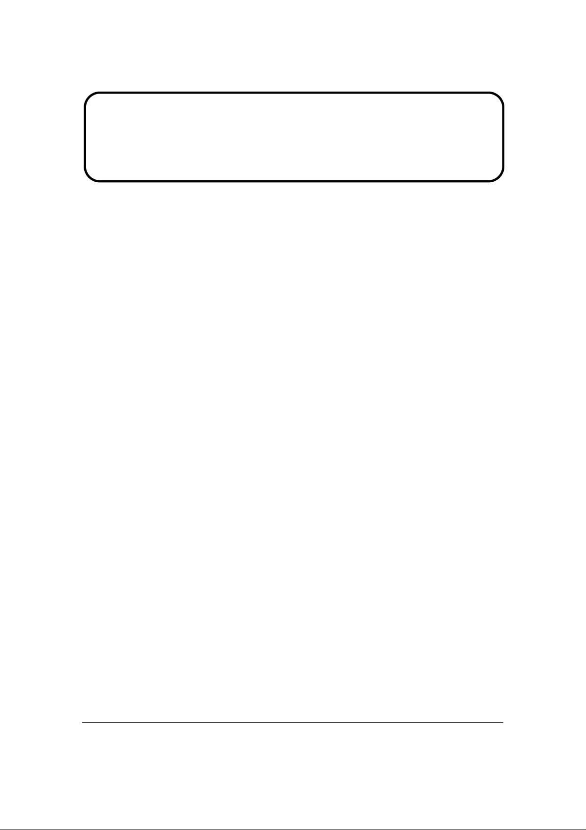
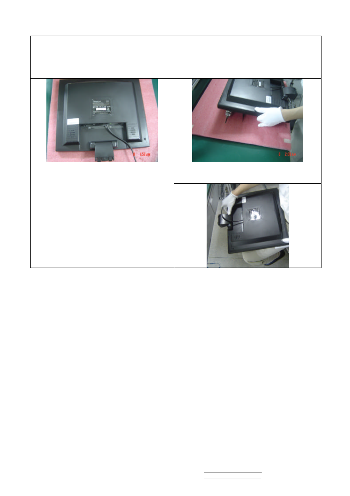
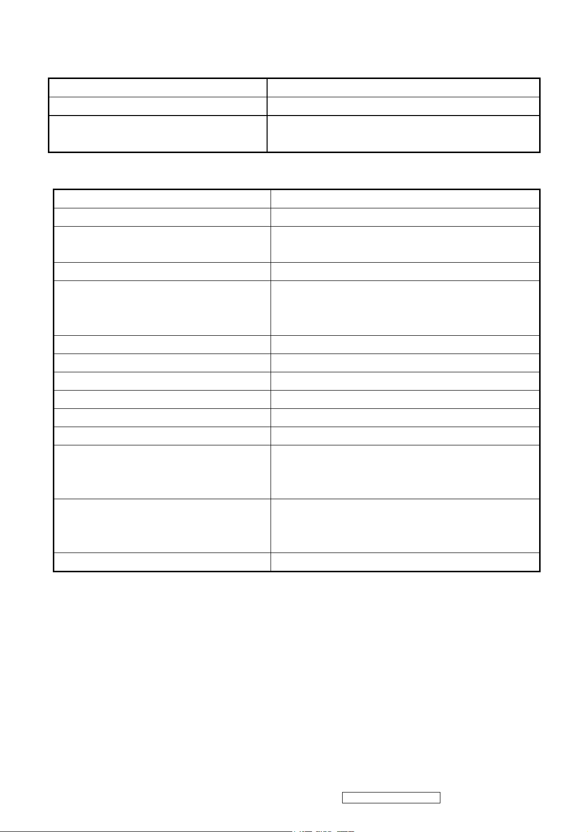
Handing and Placing methods
Correct methods Incorrect methods
Only touch the metal frame of the LCD panel or the
front cover of the monitor, DO not touch the surfaceof
the POL
Surface of the LCD panel is pressed by fingers and that
may cause”mura”
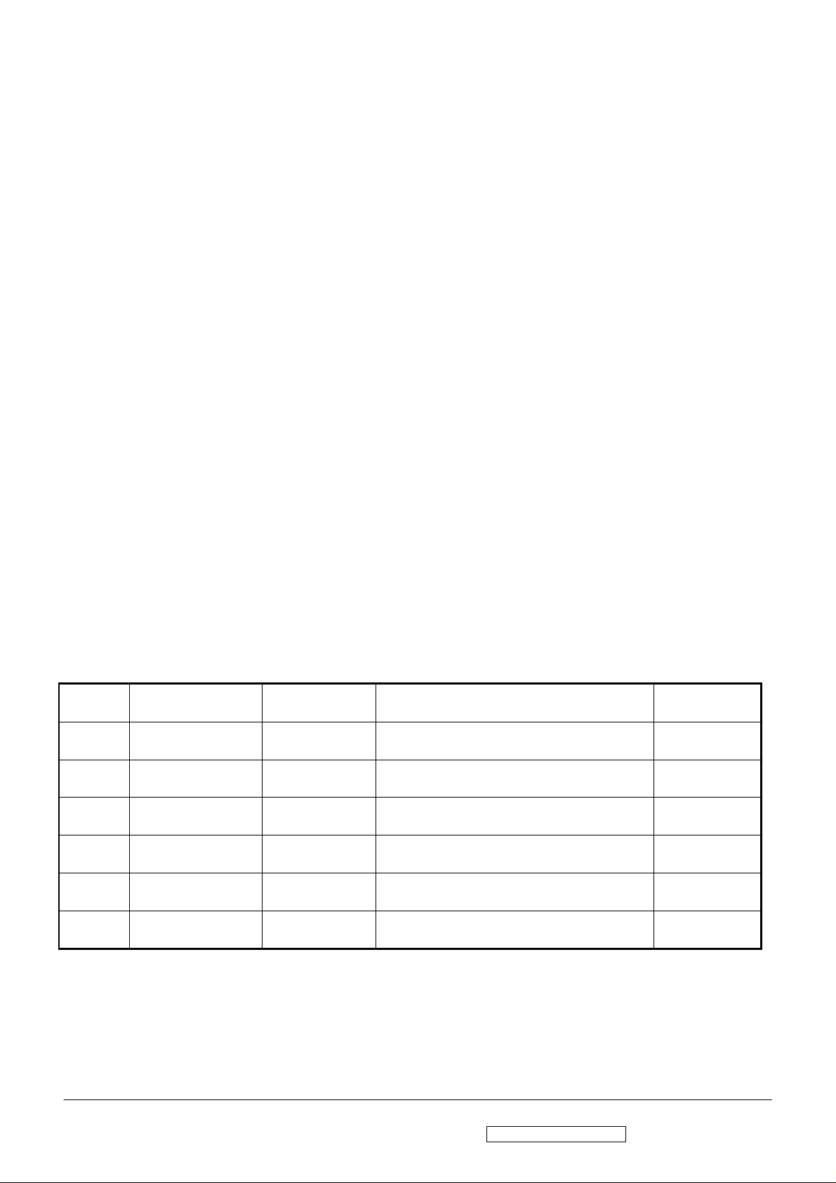
Take out the monitor with cushions Taking out the monitor by grasping the LCD panel, that
May cause”mura”
ViewSonic Corporation Confidential - Do Not Copy Q9b-2
3
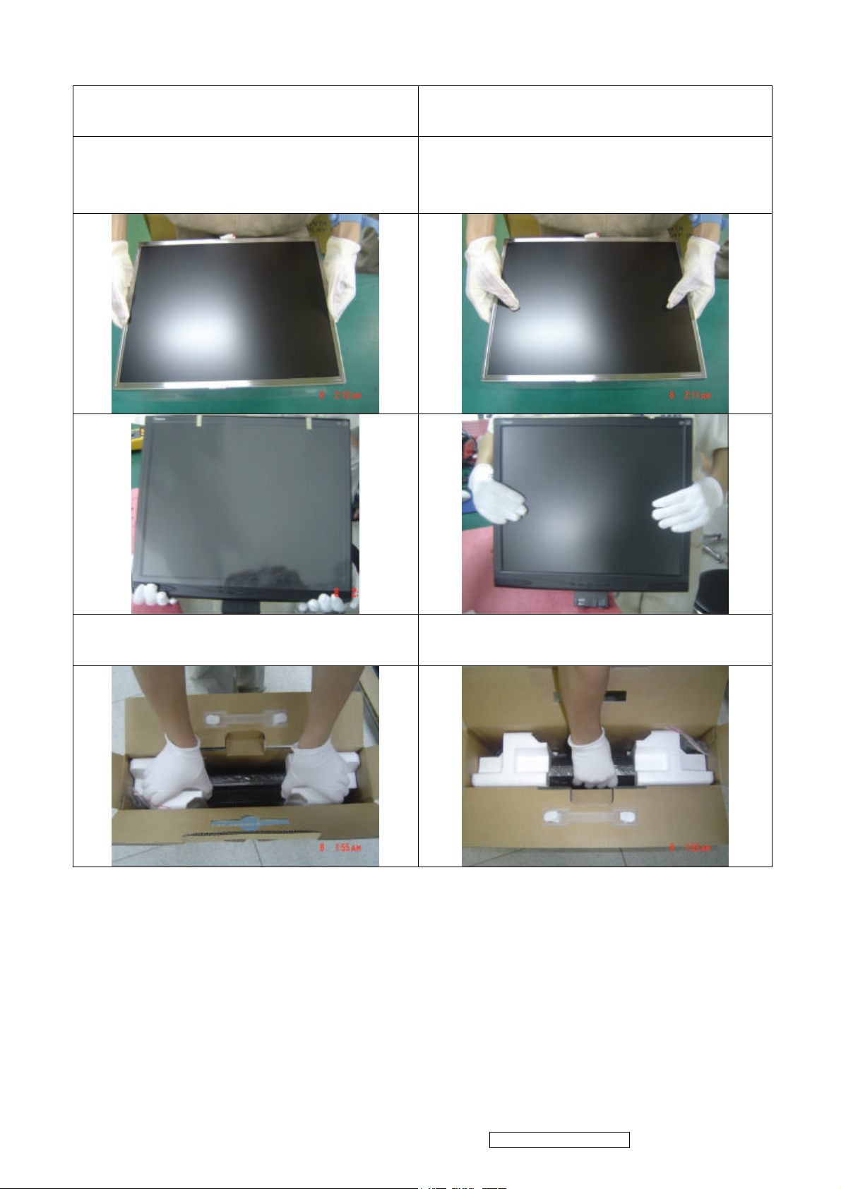
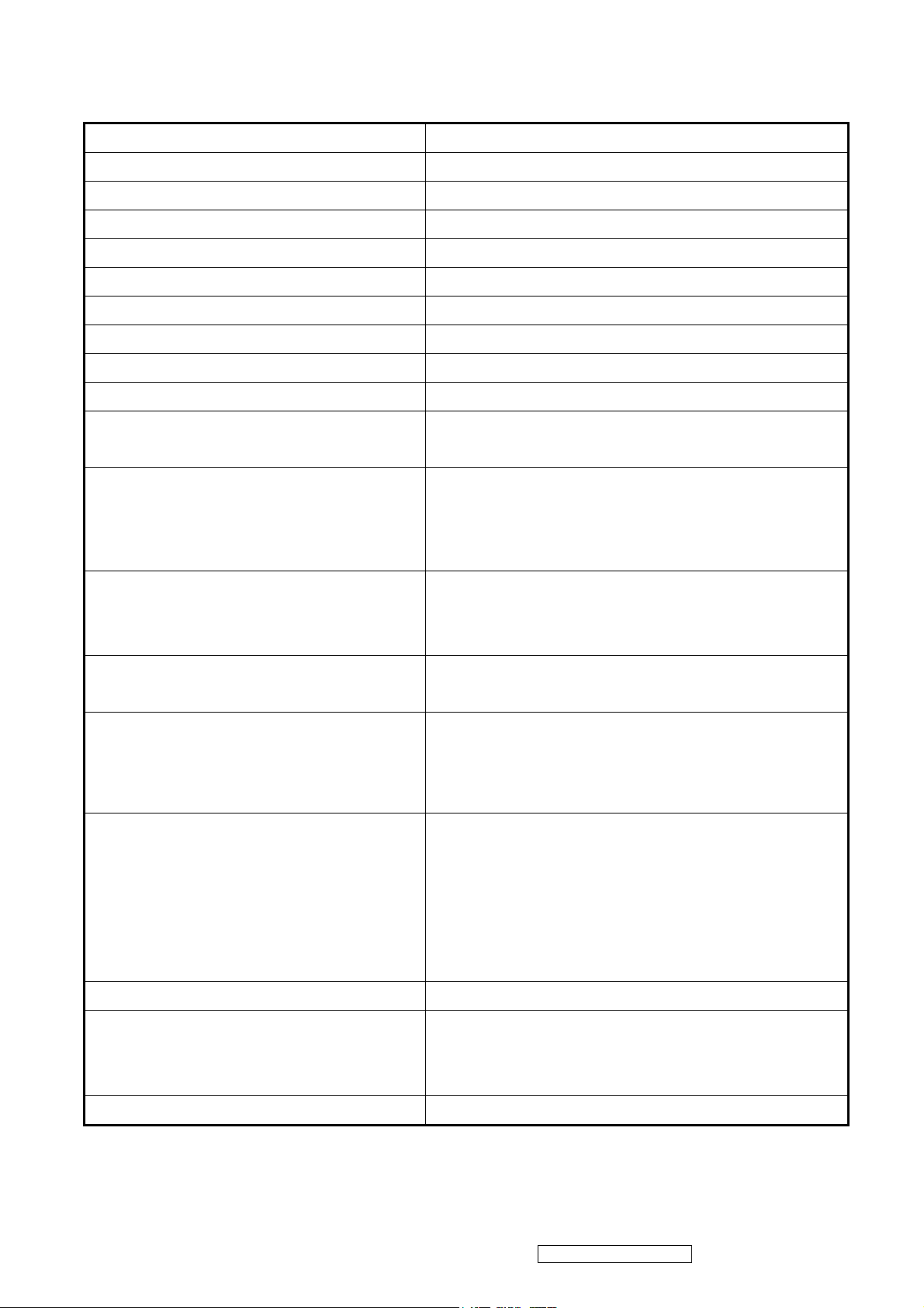
Correct methods Incorrect methods
Place the monitor on a clean and soft foam pad Placing the monitor on a foreign objects, that could
scratch The surface of the "Panel" or cause "mura"
The panel is placed facedown the lap,that may cause
"mura"
ViewSonic Corporation Confidential - Do Not Copy Q9b-2
4
2. Specification
2-1 GENERAL specification
Test Resolution & Frequency 1280x1024 @ 75Hz
Test Image Size Full Size
Contrast and Brightness Controls
Factory Default:
Contrast = 90%, Brightness = 100%
2-2 VIDEO INTERFACE
Input Connector (refer the appendix A) DB-15 (Analog)
Default Input Connector Defaults to the first detected input
Equal to twice the weight of the monitor for five
Video Cable Strain Relief
minutes
Video Cable Connector DB-15 Pin out Compliant 2B
Video RGB (Analog)
Video Signals
Separate Sync
TMDS (Digital)
Video Impedance 75 Ohms (Analog), 100 Ohms (Digital)
Maximum PC Video Signal 950 mV with no damage to monitor
Maximum Mac Video Signal 1250 mV with no damage to monitor
Sync Signals TTL
DDC2B Compliant with Revision 1.0
Sync Compatibility Separate Sync
Shall be compatible with all PC type computers,
Video Compatibility
Macintosh computers, and after market video
cards
640x350, 720x400, 640x480, 800x600, 832x624,
Resolution Compatibility
1024x768, 1152x864,
1152x870, 1280x960, 1280x1024
Exclusions Not compatible with interlaced video
2-3 USB INTERFACE
N/A
ViewSonic Corporation Confidential - Do Not Copy Q9b-2
5
2-4 POWER SUPPLY
Internal Power Supply FSP FSP035-1PI01ZT
Input Voltage Range 90 to 264 VAC
Input Frequency Range 47.5 to 63 Hertz
Short Circuit Protection Output can be shorted without damage
Over Current Protection 5.0 A typical at 12.0 VDC
Leakage Current 3.5mA (Max) at 254VAC / 60Hz
Efficiency 80 % typical at 115VAC Full Load
Fuse Internal and not user replaceable
Power Dissipation 36W(typ) 40W(max)
Max Input AC Current 1.5 Arms @ 90VAC, 0.75 Arms @180VAC
Inrush Current (Cold Start)
Power Supply Cold Start
Power Supply Transient Immunity
Power Supply Line Surge Immunity
Power Supply Missing Cycle Immunity
50 A (max) @ 115VAC
90 A (max) @ 230VAC
Shall start and function properly when under full
load, with all combinations of input voltage, input
frequency, and operating temperature.
Shall be able to withstand an ANSI/IEEE
C62.41-1980 6000V 200 ampere ring wave
transient test with no damage.
Shall be able to withstand 1.5 times nominal line
voltage for one cycle with no damage.
Shall be able to function properly, without reset or
visible screen artifacts, when ½ cycle of AC power
is randomly missing at nominal input.
The power supply shall not produce audible noise
that would be detectable by the user. Audible
Power Supply Acoustics
shall defined to be in compliance with ISO 7779
(DIN EN27779:1991) Noise measurements of
machines acoustics. Power Switch noise shall not
be considered.
Power Saving Operation(Method) VESA DPMS Signaling
On Mode < 36W(Typ) / 40W (max)
Power Consumption
Active Off < 1 W @ 120 Vac /
< 1.5W @ 220Vac
Recovery Time On Mode = N/A, Active Off < 3 sec
ViewSonic Corporation Confidential - Do Not Copy Q9b-2
6

2-5 ELECTRICAL REQUIREMENT
The vertical image size might not full
Horizontal / Vertical Frequency
Horizontal Frequency 30 – 80 kHz
Vertical Refresh Rate 55 – 75 Hz.
Maximum Pixel Clock 135 MHz
Sync Polarity Independent of sync polarity.
Timing Table
Analog
Composite
Separated
Item
1 640 x 350 @ 70 Hz, 31.5 KHz
2 640 x 480 @ 60 Hz, 31.5 KHz
3 640 x 480 @ 67 Hz, 35 KHz
4 640 x 480 @ 72 Hz, 37.9 KHz
5 640 x 480 @ 75 Hz, 37.5 KHz
6 720 x 400 @ 70 Hz, 31.5 KHz
7 800 x 600 @ 56 Hz, 35.1 KHz
8 800 x 600 @ 60 Hz, 37.9 KHz
9 800 x 600 @ 72 Hz, 48.1 KHz
Timing
SOG
Digital - TMDS
Remark
screen
(Vertical position = center).
10
11 832 x 624 @ 75 Hz, 49.7 KHz
12
13
14
15
16
17
18 1280 x 1024 @ 60 Hz, 64 KHz
19 1280 x 1024 @ 75 Hz, 80 KHz
800 x 600 @ 75 Hz, 46.9 KHz
1024 x 768 @ 60 Hz, 48.4 KHz
1024 x 768 @ 70 Hz, 56.5 KHz
1024 x 768 @ 75 Hz, 60.2 KHz
1152 x 864 @ 75 Hz, 67.5 KHz
1152 x 870 @ 75 Hz, 68.7 KHz
1280 x 960 @ 60 Hz, 59.7 KHz
Primary Presets
1280x1024 @ 75Hz
User Presets
Number of User Presets (recognized timings) Available: 10 presets total in FIFO configuration
Changing Modes
● Maximum Mode Change Blank Time for image stability : 3 seconds (Max), excluding “Auto Adjust” time
● The monitor needs to do “Auto Adjust” the first time a new mode is detected
(see section “0-Touch™ Function Actions”)
● While running Change Mode, Auto Adjust or Memory Recall, the image shall blank
ViewSonic Corporation Confidential - Do Not Copy Q9b-2
7
2-6 FRONT PANEL CONTROLS AND INDICATORS
Front Panel Hardware Controls
Power Switch (Front Head) Power Control, soft Power Switch.
Power LED (Front Head) Green – ON
Orange – Active Off
Dark = Soft Power Switch OFF
Front Panel Controls
(Head; From left to right)
Button Icon Function
Button1
Button2
Button3
Button4
Button5
Select(backward)
Select(forward)
Power
Adjust Down
-
Adjust Up
+
Reaction Time OSD must fully appear within 0.5s after pushing Button 1
Short Cuts Function from the button(s)
Button 1 Auto Image Adjust.
Button 2 Main Menu
Button 4 Mute on/off
Button 5 Volume OSD
Button 4 + Button 5
+ Button 3
Factory Mode
(The Burning mode is build in Factory mode)
Remark : All the short cuts function are only available while OSD off
ViewSonic Corporation Confidential - Do Not Copy Q9b-2
8

Function descriptions
Main Menu Controls
The Main Menu OSD include most of control functions.
Please refer to APPENDIX B (Main Menu OSD Table) for the detail.
Factory Default OSD Actions
Memory Recall action on the analog and digital mode as below
1. Set the factory defaults as shown in Section 2-8
2. Clean all the mode setting buffer
3. Execute Auto Image Adjust
0-Touch™ Function Actions
1. Execute Auto Image Adjust when new mode detected, and save the settings to buffer for
further use
2. It should be reset by Memory Recall function
(Should not reset by power off, power unplug and others)
OSD Auto Save
The OSD shall save new settings when it is turned off by the user or when it times out.
There shall not be a separate save
Factory Defaults
Item Defaults
Contrast 90
Brightness 100
Color Setting NATIVE
ViewSonic Corporation Confidential - Do Not Copy Q9b-2
9

2-7 AUDIO INTERFACE (SPEAKER SPECIFICATION)
Speaker specification
Line input connection 3.5 mm stereo jack
Line input signal 0.7 Vrms
Line input impedance 18 kOhm
Maximum power output (Electric) 1 W@ < 15 % distortion
Signal to Noise Ratio 50 dB
Frequency response 200 Hz – 10 Khz
Distortion < 5 % THD (@1kHz)
There should be no audible vibration with
Vibration
volume at 100% and treble / bass at
default.
There should be no affect on the screen
Screen image
image stability under any conditions.
Connector PC99 requirement Audio in Lime Green pantone # 577C
Cable type / length 3.5mm stereo cable / 1.8m length
Speakers should be off when the rest of
Audio DPMS
the monitor is in power saving.
Under following conditions, there should
be no sympathetic heard
Sympathetic
1. input <=0.7Vrms
2. Volume OSD <=80
Distance =30cm ±5cm
ViewSonic Corporation Confidential - Do Not Copy Q9b-2
10
2-8 Panel Characteristics :
st
and 2nd Source Panel
1
st
Model number 1
Source Panel: Hannstar HSD190ME13-A16
nd
Source Panel: Hannstar HSD190ME13 -A10
2
Type Active Matrix TFT, TN technology
Active Size 19”
Pixel Arrangement RGB Vertical Stripe
Pixel Pitch 0.294 mm
Glass Treatment Anti-Glare
# of Backlights 4 CCFL
Backlight Life 40000 Hrs (Min)
50000 Hrs (Typ)
300 cd/m2 (Typ after 30 minute warm up) Luminance (Center) –
CCT = User Color (R/G/B=100%),
Contrast/ Brightness = Max
240 cd/m2 (Min after 30 minute warm up)
Brightness Uniformity 75 % (Typ) / 70 % (Min)
Contrast Ratio 700 :1 (Typ)
450 : 1 (Min)
Color Depth 16.2 million colors (6+2 bit panel)
Typical:
H = 150 degrees
Viewing Angle H, V, D (CR >10)
V = 135 degrees
Minimum:
H = 130 degrees
V = 115 degrees
Typical:
Viewing Angle H, V, D (CR >5)
H = 160 degrees
V = 155 degrees
Response Time
10%-90% @ Ta=25°C
On/Off
Typical = 8 ms
Maximun = 12 ms
Mercury
3.0 mg per lamp
Panel Defects Please see Panel Quality Specificat ions.
*Over 50% units per shipment shall meet the Typical value above.
ViewSonic Corporation Confidential - Do Not Copy Q9b-2
11
2-9 IMAGE PERFORMANCE
Display Size
Horizontal Display Size, Primary Preset Full Screen
Vertical Display Size, Primary Preset Full Screen
Luminance
Lv (Max) –Condition:
Brightness / Contrast = 100%
Color Temperature = User (R/G/B=100)
Lv (NATIVE) –Condition:
Brightness = Default / Contrast = Default
Color Temperature = NATIVE
Lv (COOL) –Condition:
Brightness = Default / Contrast = Default
Color Temperature = COOL
Lv (WARM) –Condition:
Brightness = Default / Contrast = Default
Color Temperature = WARM
Contrast Ratio
CR(Max) –Condition:
Contrast / Brightness = 100%
Color Temperature = User (R/G/B=100)
Lv (Max) = The Luminance requirement of
section 2-6 “TFT LCD PANEL”
Lv (NATIVE) / Lv (Max) x 100% > 85%
Lv (COOL) / Lv (Max) x 100% > 70%
Lv (WARM) / Lv (Max) x 100% > 70%
Same as the Contrast Ratio in section 2-6
“TFT LCD PANEL”
Saturation
Contrast = Default
Brightness = Default
No visible saturation
Test pattern = 128-gray
Preset Color Temperatures
Color Temperature = WARM
(CCT around 5500K)
Color Temperature = NATIVE
(CCT around 6500K)
Color Temperature = COOL
(CCT around 9300K)
x = 0.332 ± 0.03
y = 0.348 ± 0.03
x = 0.313 ± 0.03
y = 0.329 ± 0.03
x = 0.283 ± 0.03
y = 0.298 ± 0.03
Video Cards Compatibility
Peaking Performance : Peaking is not adjustable
Raster Artifacts
● Video Artifacts : No visible streaking, sag, or smearing artifacts when driven by the
specified video cards in the primary mode and after user adjustment to best condition
● Power Supply, and Grounding Artifacts : No visible artifacts in any specified video mode
within the horizontal or vertical frequency range of the monitor
● Temperature Drift : Image shall not drift or lose fine-tune adjustment
ViewSonic Corporation Confidential - Do Not Copy Q9b-2
12
2-10 MECHANICAL
“Delta E” in the 1976 CIE L*a*b colorspace.
Desktop
Dimension 418 mm (W) x 408 mm (H) x 184 mm (D)
16.5" (W) x 16.1" (H) x 7.2" (D)
Monitor Weight 4.9 Kg (10.8 lbs)
Head Only / Wall Mount
Dimension 418 mm (W) x 363 mm (H) x 57 mm (D)
16.5" (W) x 14.3" (H) x 2.2" (D)
Monitor Weight 4.6 Kg (10.1 lbs)
Ergonomics
Tilt Up
Tilt Down
+15º ±2 º
-5 º ±2 º
Cabinet Material
Display Head Plastic Material ABS-94HB
Neck/Base Plastic Material ABS-94HB
All internal plastic cabinet components shall be
Internal Plastic Cabinet Components
in compliance with the requirements of MPR II
Front Bezel Color
Neck, Base, Speaker Cover, Rear Cover
and Rear Logo Color
Cabinet Color Drift Due To UV-Light
The reference for the Front Bezel is the Black
color chip provided by ViewSonic
The color difference between any two cabinet
components shall be less than 0.80 “Delta E”,
in the 1976 CIE L*a*b Colorspace.
The reference for the Neck, Base, Speaker
Cover, Rear Cover and Rear Logo is the Black
color chip provided by ViewSonic
The color difference between any two cabinet
components shall be less than 0.80 “Delta E”,
in the 1976 CIE L*a*b Colorspace.
The color drift due to UV-Light shall be less than
3.0
Testing shall be performed according to the
requirements of ASTM Test Method D4459-93.
Cabinet Texture
Samples
ViewSonic Corporation Confidential - Do Not Copy Q9b-2
Mold-Tech # 11010 used on all external textured
surfaces.
The supplier shall submit textured color chips,
plastic material specifications, and Material
Safety Data Sheets for approval.
13
3. Front Panel Function Control Description
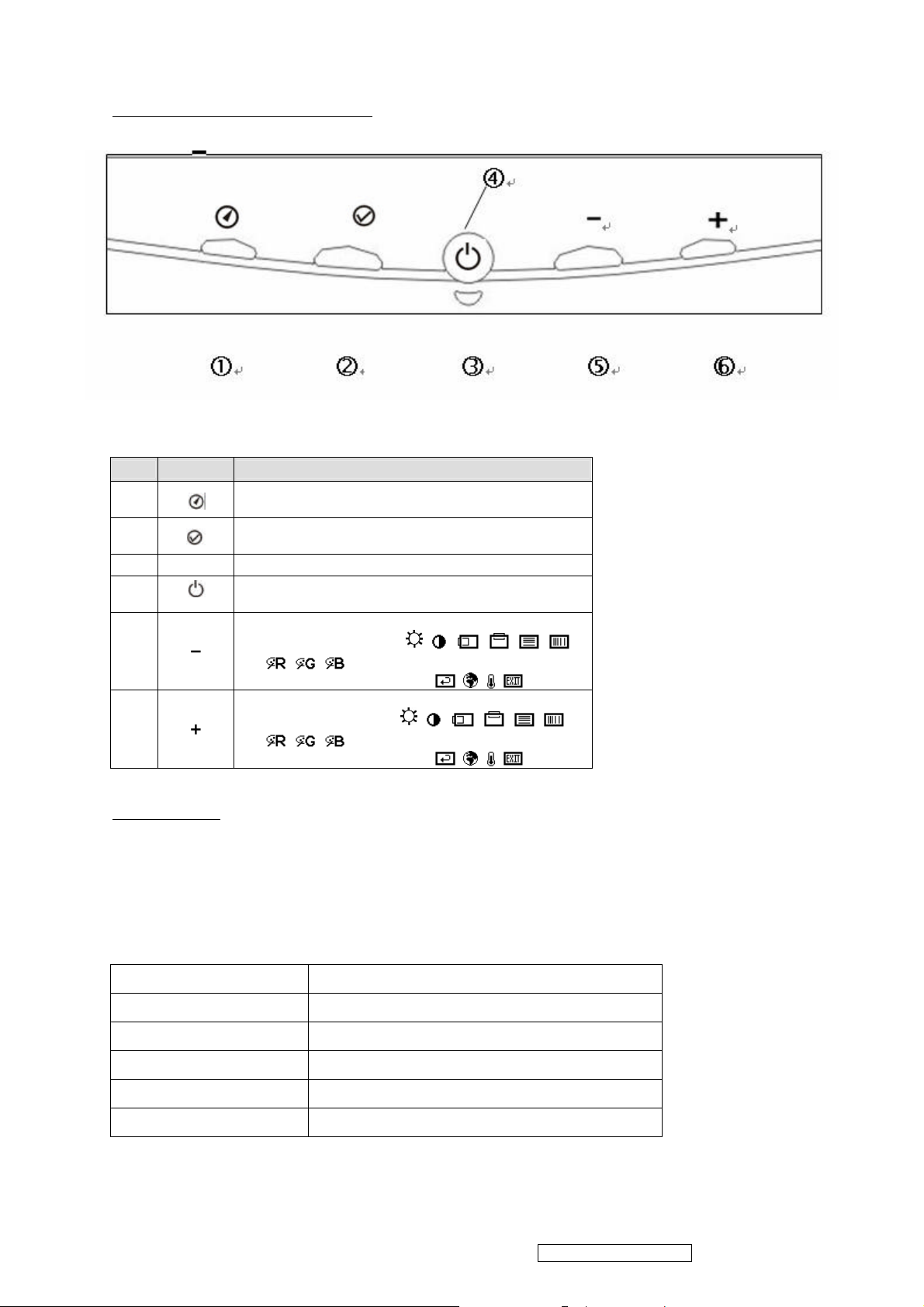
3.1 Functional Description of Controls
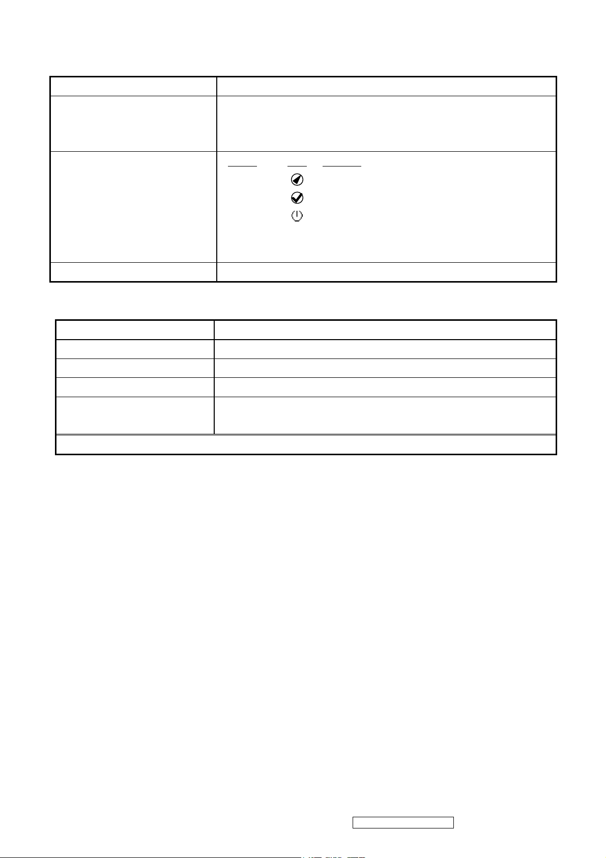
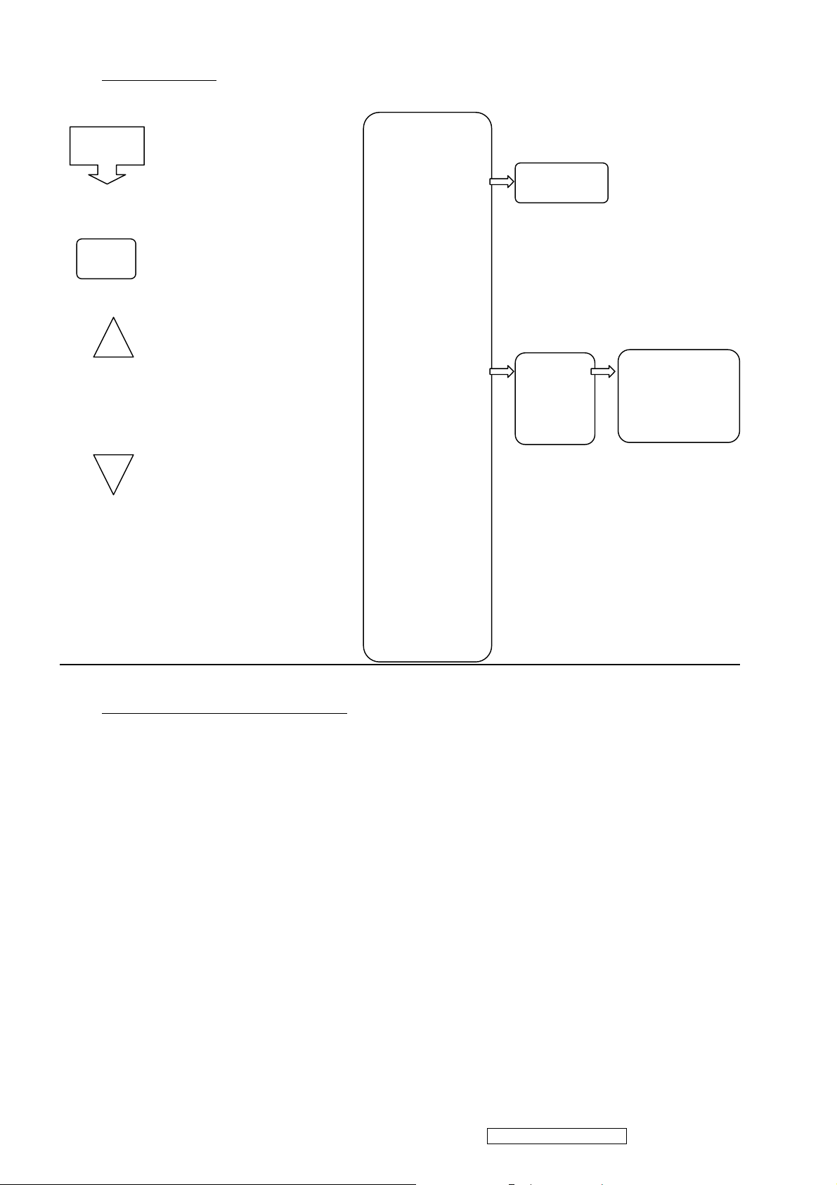
a. User Control Panel
b. Description of Key Functions
. Symbol
•
‚
ƒ
„
1. Auto-adjust
1. Show the main OSD menu
2. Select the next OSD icon up
2. Select the next OSD icon down
Power indicator
Turn the power on or off
Function
…
†
3.2 LED Indicator
The Model has one power LED which has two colors, Green and Amber.
LED should have enough luminance for clear viewable.
Some monitor status area indicated by using this LED, as follows:
Power LED
Normal On Green
Suspend Amber
Active Off Off
1. Show the mute OSD.
2. Decrease a function’s (
3. Move to the next function (
1. Show the volume OSD menu
2. Increase a function’s (
3. Move to the next function (
)
)
value.
value.
) left
) right
Out of Range Amber
No Input Signal Amber (OSD ON)
ViewSonic Corporation Confidential - Do Not Copy Q9b-2
14
3.3 User Adjustment (At Analog Signal input)
Hot Key
OSD
Brightness Up
Brightness Down
RGB Mode
Auto Adjuster
Brightness
Contrast
H position
V position
Phase
Clock
Color
Slider Bar
User
Native
Cool
Color Red
Color Green
Color Blue
Language
3.4 Specification (at all Present Timing)
a. BRT / CONT:
Picture background shall become brighter with BRIGHTNESS at its MAX position, and shall become
darker at its MIN position.
Contrast of picture shall be changed by adjusting contrast value.
b. Adjusted Range for H/V Center : ±10mm or more / ±5mm or more
c. Adjusted Range for H Phase / Pitch : >60 steps / ±50 dots
d. Color : Standard Shipping Condition- Native
Preset Color Mode - Cool, Native, Warm.
User Adjustment Mode - Users can adjust each R or G or B color individually.
Native: x=0.313±0.015;y=0.329±0.015
Cool :x=0.283±0.015;y=0.297±0.015
Warm : x=0.346±0.015;y=0.359±0.015
ViewSonic Corporation Confidential - Do Not Copy Q9b-2
15
e. Recall : Recall include Brightness, Contrast, Volume, OSD Position, OSD Time, and execute
D G
A C
Auto Adjust.
f. Language: Users can choose one of the eight languages:English, French, German, Spanish and
Italian, Russian, Tradition Chinese, Simplify Chinese.
g. Power: Pushing Power button shall cause the monitor to be turned ON and LED to be
illuminated.
Pushing Power button again shall cause the monitor to be turned OFF and LED to be OFF.
3.5 Other User/Service Information
a. SIGNAL OVER RANGE:
If the horizontal or vertical or both input signal frequency exceed the acceptable input frequency
range, the monitor keeps indicating the “SIGNAL OVER RANGE” as the OSD information after
2 seconds. If both input signal frequencies are in the acceptable frequency range, the monitor
puts out the OSD indication and goes back to normal state.
b. RGB NO INPUTSIGNAL:
In case of the pin 14 is +5V, the monitor recognizes PC is connected. Otherwise, the pin 14 is
low (approx. 0V), horizontal or vertical input signals are not exist, the monitor displays OSD
information〝RGB NO INPUTSIGNAL〞5 seconds, then goes to power save.
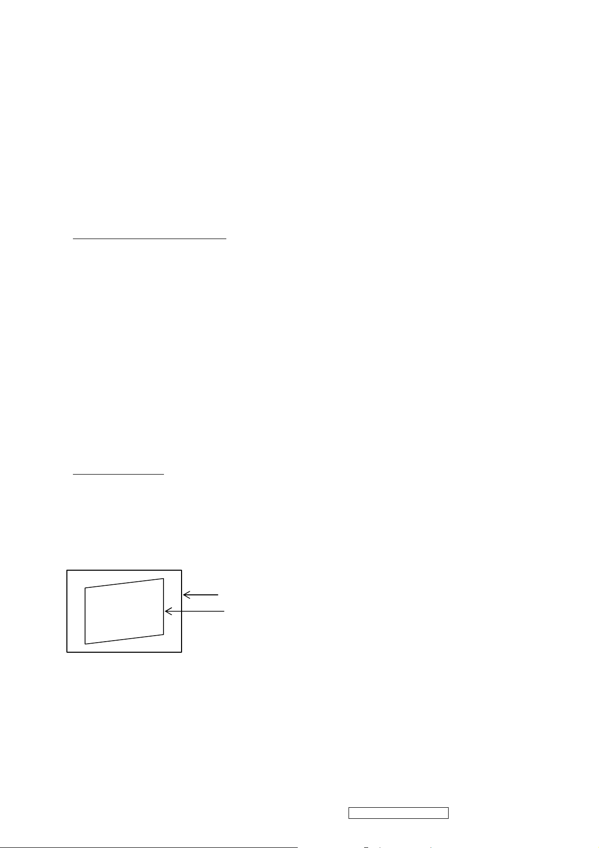
3.6 Picture Size & Tilt (Primary mode only; to be checked in shipping condition.)
a. Picture Size: <All Models> Follow Panel Spec.
b. Tilt:
| AB- CD| = Tilt on top ≦ 1mm
| EF - GH| = Tilt on bottom ≦ 1mm
| BB’-EE’| ≦ 1mm (at left side)
B’
B
E
D’
bezel
video
G’
E’
| DD’-GG’| ≦ 1mm (at right side)
F H
ViewSonic Corporation Confidential - Do Not Copy Q9b-2
16
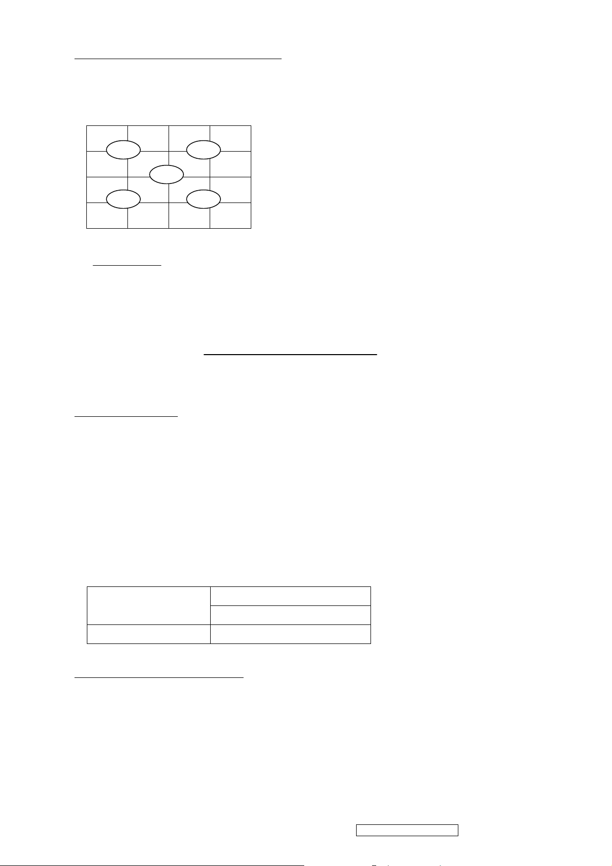
3.7 Brightness Uniformity and Contrast Ratio
C D
a. Brightness Uniformity:
128 640 1152
B
E
A
102
512
922
Bmax = MAX (BA, BB, BC, BD, BE)
Bmax - Bmin Bmin = MIN (BA, BB, BC, BD, BE)
≦ 20%
Bmax Bave = AVE (BA, BB, BC, BD, BE)
b. Contrast Ratio:
The contrast ratio is measured at point A and calculated by using the following formula
Luminance with all pixels in white
Contrast ratio (CR) = ≧ 200 (According to HANNSTAR
Luminance with all pixels in black HSD190ME13-A02)
3.8 Shipping Luminance
a. Condition Input signal : Full white pattern
Controls : Color temperature of Office
Cont./Brt. : Default value
Measurement point : One point at the center of the picture.
Warm-up time : 30 minutes.
Color analyzer : CA-210
c. Shipping luminance (center)
Shipping Luminance
Color Temperature
19”
Native
≧ 200 cd / ㎡
3.9 Maximum / Minimum Luminance
a. Condition Input signal : Full white pattern (Primary mode)
Measurement point : Center of LCD screen
Color Analyzer : CA-210
Maximum : BRT→Max.
CONT→Max.
ViewSonic Corporation Confidential - Do Not Copy Q9b-2
17

b. Specification: Native only
(1) ≧200 cd/㎡
3.10 Black Level
a. Gray Scale Condition Input signal: 32 Gray scale (Primary mode)
Controls : CONT./BRT. primary setting, other shipping setting
condition.
b. Specification:Native (1) The first bar from black of gray scale pattern shall be cut off.
(2) The last bar from the bright of gray scale pattern shall be
discrimination.
3.11 Picture Quality
a. Condition BRT : MIN. ~ MAX.
CONT : MIN. ~ MAX.
*Inspection of picture quality shall be made at the distance of 50 cm in front of LCD surface.
b. Full White Signal
Condition : Input signal – Full white signal
Specification: The following electrical defects shall not be so conspicuous.
(ITU-R 4.5 or better in primary mode, and ITU-R 4.0 or better in other modes)
(2) ringing, seam, etc.
(3) flicker, noise, beat, etc.
(4) shading, etc.
(5) saturation of video power supply, etc.
c. Inverted Crosshatch Signal
Condition : Input signal – Inverted crosshatch signal
Specification: Following electrical defects shall not be so conspicuous.
(ITU-R 4.5 or better in primary mode, and ITU-R 4.0 or better in other modes)
(1) video ringing, over shoot, smear, etc.
(2) vertical jitter, horizontal jitter, picture vibration, etc.
d. Gray Scale Signal
Condition : Input signal – Gray scale signal
Specification: Following electrical defects shall not be so conspicuous.
(ITU-R 4.5 or better in primary mode, and ITU-R 4.0 or better in other modes)
(1) Oscillation, noise, beat, shading, etc.
ViewSonic Corporation Confidential - Do Not Copy Q9b-2
18

3.12 EDID DATA
a. Condition : Maintain Mode
b. Specification : FOR RGB
DDC EDID 128 BYTES DATA STRUCTURE
No. Item EDID Data or Definition
00 Header 00 FF FF FF FF FF FF 00
08 ID Manufacturer Name 10 8C (DDL)
0A ID Product Code 00 00 (0)
0C ID Serial Number 00 00 00 00 (0)
10 Week Of Manufacture Week of manufacture
11 Year Of Manufacture Year of manufacture
12 EDID Version,Revision 01 03
14 Video Input Definition 7E(Analog signal,0.700,0.000(0.7
Vp-p),Black-to-Black, ,Separate Syncs, Composite Syncs, Sync
on Screen )
15 Max. H. Image Size 25 (37cm)
16 Max. V. Image Size 1E(30cm)
17 Display Transfe
Charac.(gamma)
18 Feature Support(DPMS) EB(Stand-by,Suspend,Active Off supported,R/G/B color display)
19 Color Characteristics Per TFT measurement(See NOTE1)
23
26 Standard Timing Identification 81 80— 1280*1024@60Hz; 71 4F— 1152*864@75Hz z;
36 Detailed Timing 1 Description BC 34 00 98 51 00 2A 40 10 90 13 00 78 2D 11 00 00 1E
48 Detailed Timing 2 Description 00 00 00 FF 00 20 44 44 4C 30 30 30 30 30 20 20 20 20
5A Detailed Timing 3 Description 00 00 00 FD 00 37 4B 1E 50 0E 00 0A 20 20 20 20 20 20
6C Detailed Timing 4 Description 00 00 00 FC 00 4C 4D 31 39 30 34 0A 20 20 20 20 20 20
7E Extension Flag 00
7F Checksum Per DDC Specification
Established Timings AF--(720*480@70Hz) ,(640*480@60Hz),(640*480@72Hz),
78(2.20)
(640*480@75Hz),(800*600@56Hz),(800*600@60Hz)
EF--(800*600@72Hz),(800*600@75Hz),(832*624@75Hz)
(1024*768@60Hz),(1024*768@70Hz),(1024*768@75Hz)
(1280*1024@75Hz)
00—
81 40--1280*960@75Hz; 31 46— 640x480 @66Hz
01 01-- 01 01-01 01-- 01 01--
(1280*1024@75Hz,Video Size:376mm*301mm,No Stereo)
Monitor S/N: DDL00000
(Vf:55~75Hz,Hf:30~80KHz,Pixel Clock:140MHz)
(LM1904)
NOTE 1 Panel Specification (HSD190ME13)
Color characteristics R: x=0.6475 y=0.3271
G: x=0.2920 y=0.6143
B: x=0.1416 y=0.0791
W: x=0.3096 y=0.3301
Store in EDID data=
FD 56 A5 53 4A 9D 24 14 4F 54
ViewSonic Corporation Confidential - Do Not Copy Q9b-2
19

4. Circuit Description
A. A/D converters
The ADC is a 7-bit 4-channel analog-to digital converter ,the structure of these ADCS is 7-bit
successive approximation ,analog voltage is supplied from external sources to the A/D input pins and
the result of the conversion is stored In the 7-bit data latch registers(ADC0_REG~ADC3_REG).The
A/D cannels are activated by cleaning the correspondent control bits in the ADC_CON control register,
when users write”1” into one of the enable control bits(EN_ADC0~EN-ADC3),its correspondent I/O pin
will be switched to the A/D Converter input pin
The conversion will be started by setting STRT_ADC Bit, user can monitor this bit to get the valid A/D
channel, its latched data is meaningful, the analog voltage to be measured should be stable during the
conversion operation and the variation will not exceed 1 LSB for the best accuracy in measurement
B.Scalling controller
1. VGA front end
l Built-in triple high speed ADC,PLL for analog RGB input
l Supports both non-interlaced and interlaced RGB graphic input signals
l Input signal ranges from 0.55-0.9v
l Provides RGB analog gain and offset control
l Support 64 steps (one cycle of pixel)of phase adjust
l ADC sampling rates are up to 110MHZ for x type, 160MHZ for E type Supports analog SOG
input
2. YUV Front End
l Support ITU-R BT.656 8-bit input
l Built-in YUV to RGB color space converter
3. Display
l Supports data swap to fit any panel data alignment for PCB Layout
l Built in LVDS transmitter
l Supports spectrum of output clock
4. Hot interface
l Support serial 2-wire IIC bus
l Provides 2 channel PMW
5. Power
l Power supply
l Less than 1.3W
ViewSonic Corporation Confidential - Do Not Copy Q9b-2
20

6. Video processor
l Flexible de-interlacing unit for VGA and digital YUV video input data
l Auto-calibration function for quick vide cantering, clock adjust and phase adjust
l Independent horizontal and vertical zoom in/out algorithm
l Enhanced interpolation algorithm for optimal image quality
l Provides RGB digital gain and offset control
l Dithering function supports 24-bits quality for 18-bit panel
l SRGB matrix mapping support
l 10-bit programmable gamma table for panel compensation
l Supports Hue and saturation adjustment
l Built-in POST pattern
Timing controller
l Support RSDS output
l Provides 4 differential data pairs to support 6 or 8-bit RGB data bus
l 10 General Purpose output allow suitability to different production environments
l Provide single pixel (18-24-bit) or dual pixel (36-48-bit)
l Programmable RSDS swing level
l Supports line offset function for two bank system panel
l 12 GPO internal controls 10 GPO external pin outputs
l Supports data swap to fit any panel data alignment for PCD layout
Sync Processor
l Supports separate, composite and TTL-level sync-on-Green (SOG) sync input
l Polarity detection for HSYNCI and VSYNCI
l Fast mode change detection function
ViewSonic Corporation Confidential - Do Not Copy Q9b-2
21
 Loading...