

ViewSonic PJ452 - LCD XGA Projector-4.9LBS, PJ452, VS10948 Service Manual

LCD Projector
Service Manual
ViewSonic
381 Brea Canyon Road, Walnut, California 91789 USA - (800) 888-8583
ViewSonic PJ452
(PJ452_SM Rev. 1a DEC. 2005)
Model No. VS10948
Copyright
Copyright
¤
2005 by ViewSonic Corporation. All rights reserved. No part of this publication may be
reproduced, transmitted, transcribed, stored in a retrieval system, or translated into any language or
computer language, in any form or by any means, electronic, mechanical, magnetic, optical, chemical,
manual or otherwise, without the prior written permission of ViewSonic C orporation.
Disclaimer
ViewSonic makes no representations or warranties, either expressed or implied, with respect to the
contents hereof and specifically disclaims any warranty of merchantability or fitness for any particular
purpose. Further, ViewSonic reserves the right to revise this publication and to make changes from time
to time in the contents hereof without obligation of ViewSonic to notify any person of such revision or
changes.
Trademarks
View
Sonic is a registered trademark of ViewSonic Corporation.
All other trademarks used within this document are the property of their respective owners.
Optiquest is a registered trademark of ViewSonic Corporation.
Revision History
ECR Number
Description of Changes
EditorRevision SM Editing Date
i
ViewSonic Corporation Confidential
-
Do Not Copy PJ656
1a Initial Release
BonnieT.
12/9/05

TABLE OF CONTENTS
2. Specification
3. Names of each part
5
. Troubleshooting
8. Disassembly diagram
9.
Replacement parts list
6. Service points
1. Precautions and Safety Notices
4. Adjustment
7. Wiring diagram
10. RS-232C commands
1
2
3
5
11
16
30
34
42
43
12. Connector connection diagram
51
52
11. Block diagrams
ii
ViewSonic Corporation Confidential
-
Do Not Copy PJ656
13. Basic circuit diagram
53
1. Precautions and Safety Notices
1. When replacing the lamp, use care to avoid burns to your fingers. The lamp becomes very hot
during operation.
2. Never touch the lamp with your fingers as body oil transferred to the lamp can damage the
lam
p’s useful life.
3. Never drop the lamp or jar it in any manner. This m
ay cause the lamp to burst.
4. This projector is provided with a high voltage circu
it for the lamp. Do not touch any electric
part or component after the projector has been turned on and is operating. Doing so could
induce a severe shock causing injury or death.
5. Do not touch the exhaust fan, nor block its air flow, during operation, as the fan is hot.
6. The LCD module assembly can be easily damaged during service.
If replacing the LCD
Lens/Prism assembly, do not hold the FPC of the LCD module assembly.
7. Use only the cables which are included with the projector, or are specif
ied in this manual.
1
ViewSonic Corporation Confidential
-
Be sure to read this manual before servicing. To assure safety from fi re, electric shock, injury, harmful
radiation and materials, various measures are provided in this Multimedia LCD Projector. Be sure to
read cautionary items described in the manual to maintain safety before servicing.
Caution
1. When replace the lamp, to avoid burns to your fi ngers. The lamp becomes too hot.
2. Never touch the lamp bulb with a fi nger or anything else. Never drop it or give it a shock. They may
cause bursting of the bulb.
3. This projector is provided with a high voltage circuit for the lamp. Do not touch the electric parts of
power unit (main), when turn on the projector.
4. Do not touch the exhaust fan, during operation.
5. The LCD module assembly is likely to be damaged. If replacing to the LCD/PRISM assembly, do not
hold the FPC of the LCD module assembly.
6. Use the cables which are included with the projector or specifi ed.
Service Warning
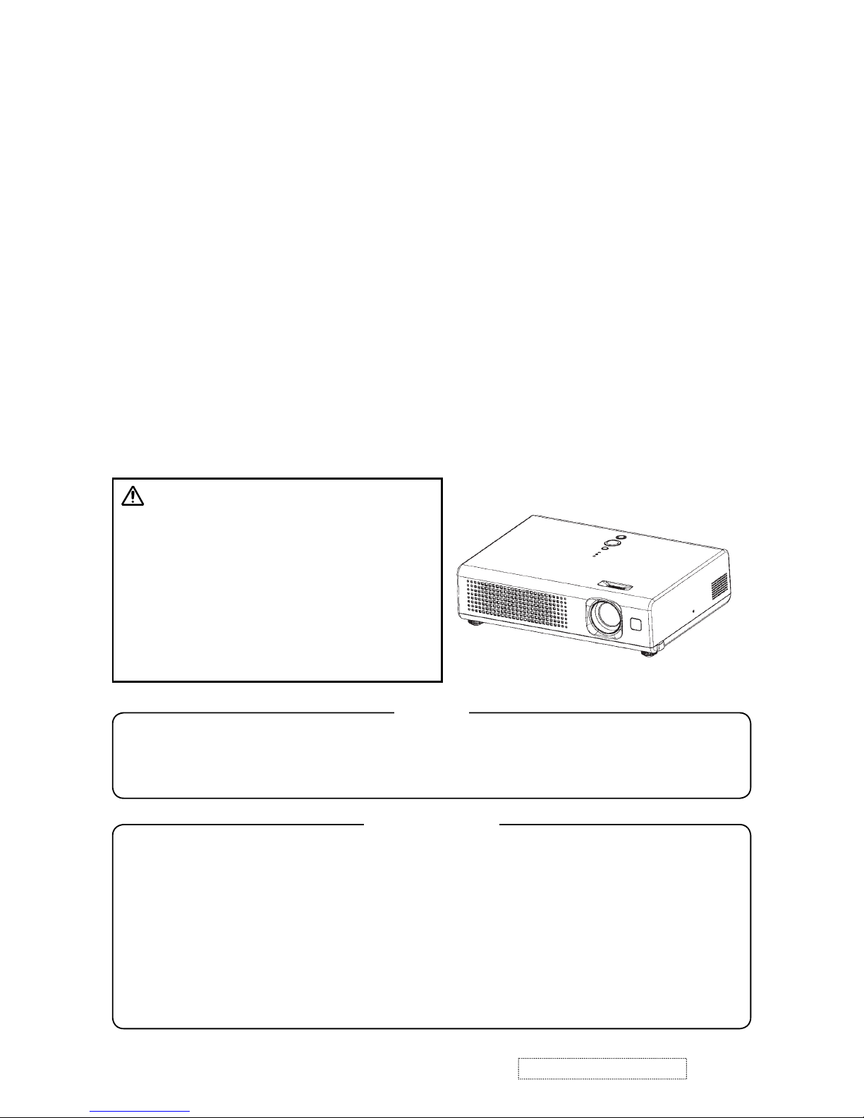
Warning
The technical information and parts shown in this
manual are not to be used for: the development,
design, production, storage or use of nuclear, chemical,
biological or missile weapons or other weapons of
mass destruction; or military purposes; or purposes that
endanger global safety and peace. Moreover, do not
sell, give, or export these items, or grant permission for
use to parties with such objectives. Forward all inquiries
to the SUPPLIER.
Do Not Copy PJ452
Features
• High Brightness
• Low Noise
• Compact Body
2. Specifications
Liquid clystal
panel
Drive system TFT active matrix
Panel size 1.5cm (0.6 type)
Number of pixels 1024 (H) x 768 (V)
Lamp 165W UHB
RGB
signal
input
RGB IN
Video : Analog 0.7Vp-p(75Ω termination)
H/V. sync.: TTL level (positive/negative)
Composite sync.: TTL level
VIDEO
signal
input
VIDEO IN 1.0Vp-p(75Ω termination)
S-VIDEO IN
Y signal : 1.0±0.1Vp-p, (75Ω termination)
C signal : 0.286±0.1Vp-p(NTSC burst signal, 75Ω termination)
0.3±0.1Vp-p(PAL/SECAM burst signal, 75Ω termination)
AUDIO IN 200mVrms, 47kΩ or more (max. 3.0Vp-p)
Speaker output 1W(mono)
Power supply AC100~120V/2.7A,AC220~240V/1.5A
Power consumption 240W
Dimensions 285 (W) x 73 (H) x 202 (D) mm (Not including protruding parts)
Weight 2.2kg(4.85lbs)
Temperature range
Operation : 5~35°C
Storage : -20~60°C
Accessories
Remote control x 1
RGB cable x 1
Power cords x 3
Batteries x 2
Filter cover for bottom up use x 1
User’s manuals x 1
2
ViewSonic Corporation Confidential
-
Do Not Copy PJ452
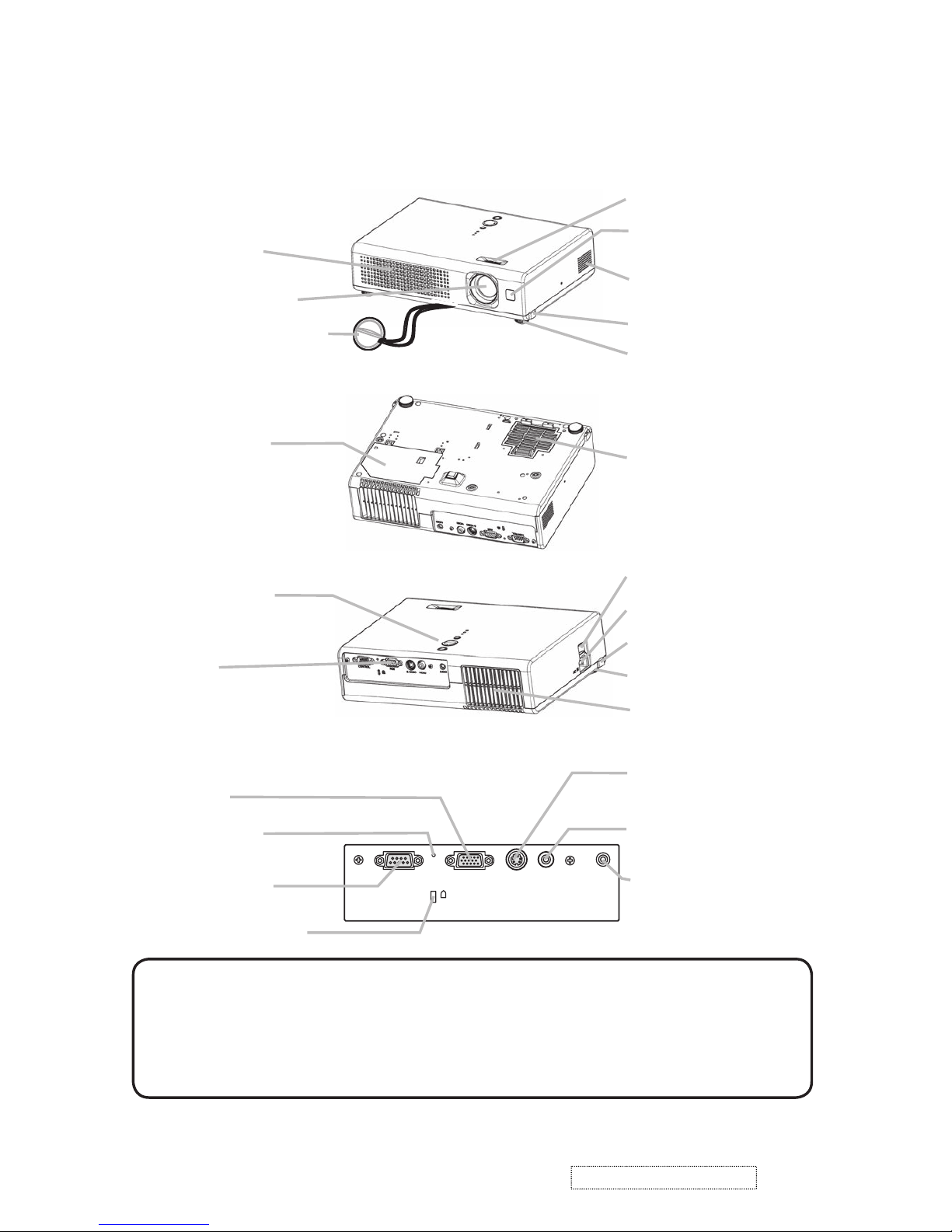
3. Names of each part
S-VIDEO
VIDEO
AUDIO
RGB
CONTROL
K
Lens
Lens cover
Filter cover
(Air filter and intake vent
are inside.)
Elevator button
Elevator foot
Remote sensor
Focus ring
Vent
AC inlet
Power switch
Elevator button
S-VIDEO port
VIDEO port
CONTROL port
Projector
Lamp cover
(Lamp unit is inside.)
Elevator foot
Bottom side
Speaker
Front-Right side
Rear-Left side
Control buttons
Ports
(See below.)
Vent
Ports
AUDIO port
Restart switch
RGB port
Kensington lock slot
NOTE (*) About Restart switch: This Projector is controlled by an internal
microprocessor. Under certain exceptional circumstances, the projector may not
operate correctly and the microprocessor will need to be reset. In such a case,
please push the Restart switch by using a cocktail stick or similar and before
turning on again, make the projector cool down at least 10 minutes without
operating. Only push the Restart switch in these exceptional instances.
Part names
●
3
ViewSonic Corporation Confidential
-
Do Not Copy PJ452
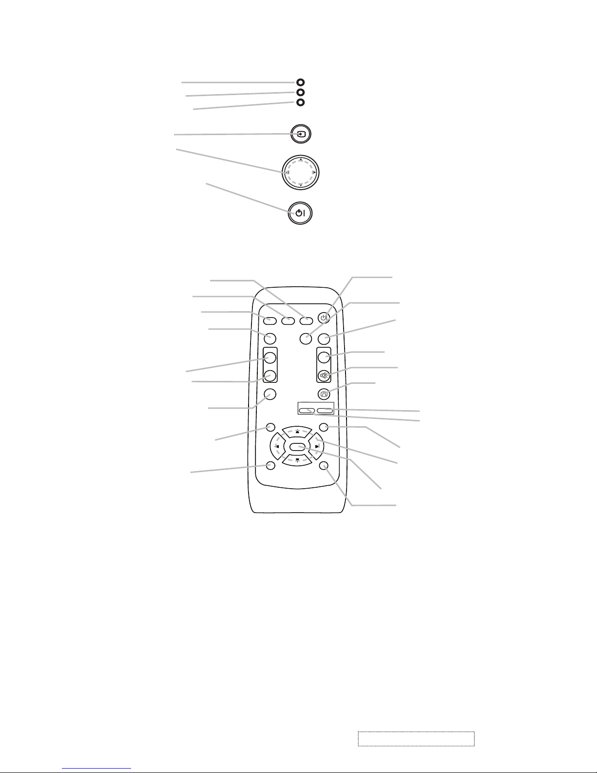
STANDBY/ON
INPUT
MENU
LAMP
TEMP
POWER
LAMP indicator
TEMP indicator
POWER indicator
INPUT button
Cursor buttons
▲,▼,◄,►
STANDBY/ON button
Controls
VIDEO
RGB
SEARCH
FREEZE
OFF
ON
MAGNIFY
ASPECT
STANDBY/ON
AUTO
BLANK
MUTE
VOLUME
KEYSTONE
POSITION
ESC
ENTER
MENU
RESET
ZOOM
+
-
emote contro
l
SEARCH button
RGB button
VIDEO button
ASPECT button
MAGNIFY
ON button
OFF button
FREEZE button
POSITION button
ESC button
TANDBY/ON button
AUTO button
BLANK button
V
O
LUME button
MUTE button
KEYSTONE button
Zoom
+ button
- button
MENU button
M
enu cursor buttons
▲,▼,◄,►
ENTER button
RESET button
4
ViewSonic Corporation Confidential
-
Do Not Copy PJ452
4. Adjustment
4-1 Before adjusting
4-1-1 Selection of adjustment
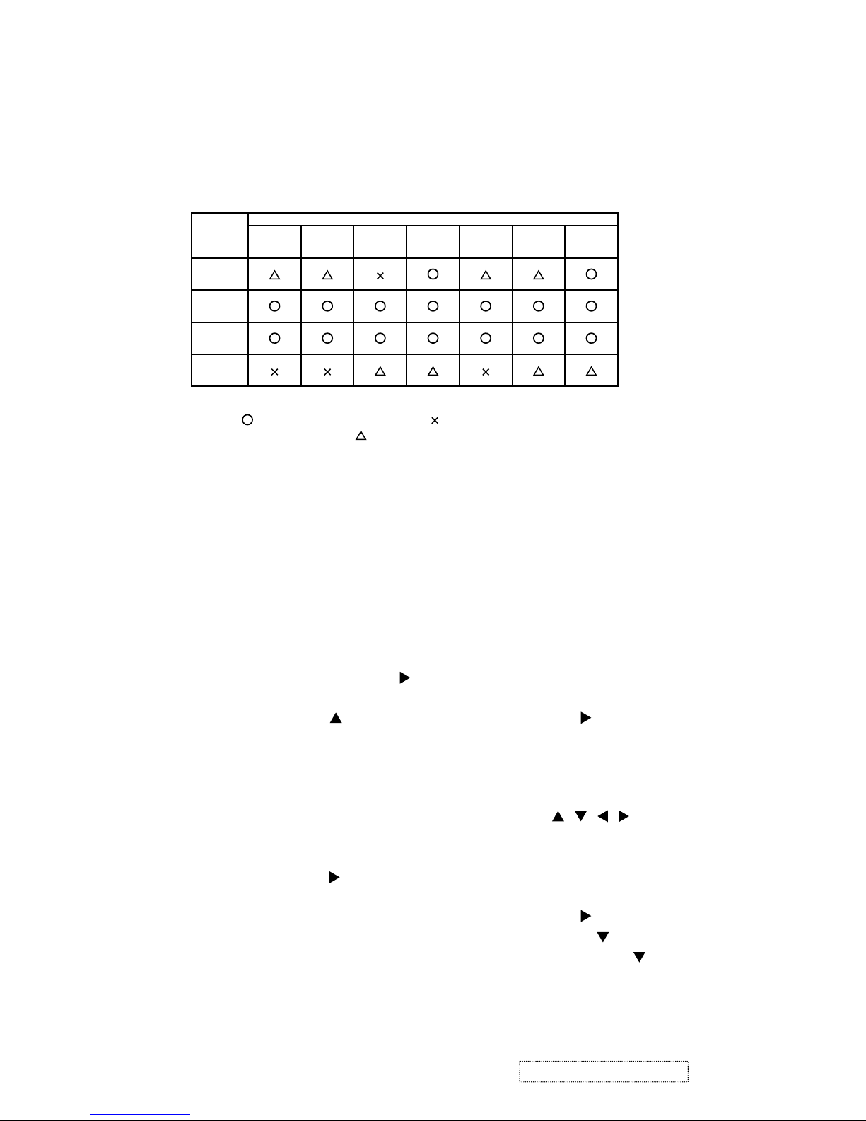
When any parts in the table 4-1 are changed, choose the proper adjusting items with the chart.
Table 4-1: Relation between the replaced part and adjustment
Replaced
part
Adjustment
Convergence
(Chap.4-2)
E-POS
(Chap.4-3)
Ghost
(Chap.4-4)
Flicker
(Chap.4-5)
NRSH
(Chap.4-6)
White
balance
(Chap.4-7)
Color
uniformity
(Chap.4-8)
Dichroic
optics unit
LCD/LENS
prism
assembly
PWB
assembly
Main
Lamp
unit
assembly
: means need for adjustment. : means not need for djustment.
: means recommended.
4-1-2 Setting of condition before adjustment
1. Before starting adjustment, warm up projector
for about 10 minutes.
2. Set Zoom Wide to Max. And project an image
with more than 1m (40 inches) in diagonal size.
3. Normalizing the video adjustment
Press the [MENU] button to display the Easy
menu. If Advance menu comes up, move to the
Easy menu.
Select RESET in the Easy menu and press [
]
or [ENTER] button to open the RESET menu
window. Choose EXECUTE with [
] button.
Note that no signal input may not allow to reset
the adjustments.
4. Select PICTURE > GAMMA in the Advance
menu to set to DEFAULT1.
Note that PICTURE menu is not selectable with
no signal input displayed.
5. Select PICTURE > COLOR TEMP > CUSTOM
in the Advance menu, then press [
] or [ENTER]
button to display the equalizing window. Set all
the values of OFFSET and GAIN in the window
to zero.
Caution: Before this performance, make a note
of your customer’s adjustments, because the
data is overwritten.
6. Perform all adjustments from the FACTORY
MENU.
Perform the following operations to display the
FACTORY MENU.
< When you use the remote control… >
a. Press the [MENU] button of remote control to
display the Easy menu. (If the Advance menu
appears, move to the Easy menu from EASY
MENU.)
b. Select the [RESET] in the Easy menu, and
then press the [
] or [ENTER] button.
c. Next, press the [RESET] button one time.
And hold the [RESET] button for 3 seconds
or more (the FACTORY MENU will appear).
< When you use the keypad… >
a. Press the [ ]/[ ]/[ ]/[ ] button of the projec-
tor to display the Easy menu. (If the Advance
menu appears, move to the Easy menu from
EASY MENU.)
b. Select the [
RESET
] in the Easy menu, and
then press the [ ] button.
c. Next, press the [
] button one time. And
repress and hold the [ ] button together
with the [INPUT] button for 3 seconds or
more (the FACTORY MENU will appear).
5
ViewSonic Corporation Confidential
-
Do Not Copy PJ452
4-4 Ghost adjustment
Signals for internal adjustment
30%
112/255
30%
0/255
Adjustment procedure
1. Make this adjustment after completing the
adjustment in 4-3.
2. Choose Advance menu > OPTION > SERVICE
> GHOST > R,G and B, and set them to zero.
3.
Use DAC-P - GHOST - R: in the FACTORY MENU
to adjust so that R color ghost is at a minimum.
(Set the adjustment value to default, and then
raise the value. When a ghost appears to the left
of a vertical line, reduce the value by 4 steps.)
4. In the same way, use DAC-P - GHOST-G: in
the FACTORY MENU to adjust so that G color
ghost is at a minimum.
5. In the same way, use DAC-P - GHOST-B: in
the FACTORY MENU to adjust so that B color
ghost is at a minimum.
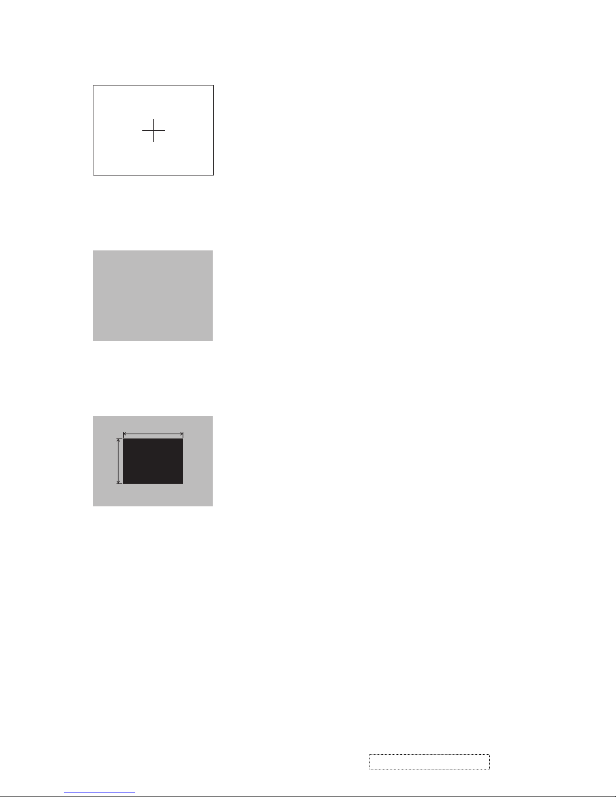
4-2 Convergence adjustment
Signal pattern for internal adjustment
Adjustment procedure
1. Open FACTORY MENU and then select
OPTION > CNV-V. Use R and/or B so that
three colors of images can be converged at
center, top and bottom of the screen.
2. In the same way, select OPTION > CNV-H and
use R and/or B so that three colors of images
can be converged at center, left and right of the
screen.
4-3
E-POS adjustment
(vertical bars adjustment)
Signal pattern for internal adjustment
112/255
Adjustment procedure
1. Make this adjustment after completing the
adjustment 4-2 Convergence adjustment.
2. Choose Advance menu > OPTION > SERVICE
> GHOST > R,G and B, and set them to zero.
3.
Open FACTORY MENU. Select DAC-P > E-POS
> R and use it so that vertical bars can disappear.
4. In the same way, select DAC-P > E-POS > G
and use it so that vertical bars can disappear.
5. In the same way, select DAC-P > E-POS > B
and use it so that vertical bars disappear.
6
ViewSonic Corporation Confidential
-
Do Not Copy PJ452
4-5 Flicker adjustment
(V.COM adjustment)
Signals for internal adjustment
Adjustment procedure
1. Make this adjustment after completing the
adjustment in 4-4 Ghost adjustment.
2.
Use DAC-P - V.COM - R: in the FACTORY
MENU to adjust so that the flicker at the center of
the screen is less than the flicker at the periphery.
(When the flicker is about the same across the
whole screen, adjust so that the flicker at the center
of the screen is somewhat less than elsewhere.)
3. In the same way, use DAC-P - V.COM-G: in the
FACTORY MENU to adjust the G color flicker.
4. In the same way, use DAC-P - V.COM-B: in the
FACTORY MENU to adjust the B color flicker.
4-7
White balance adjustment
(visual inspection)
Preparations
1. Perform these adjustments after the NRSH
adjustment described in Section 4-6.
2. Reset gamma correction before adjustment.
Place the cursor on [GAMMA] in the FACTORY
MENU, press the [RESET] key and select [DEFAULT].
Adjustment procedure
1. First, adjust the G color.
2.
Select GAMMA, SUB-CNT, and G: in the FACTORY
MENU. If the background is white solid, press the
[ENTER] key on the Remote control transmitter to
change to [G] monochrome in the 33-tone grayscale.
3. Adjust GAMMA, SUB-CNT, and G: in the FACTORY MENU so that brightness of 33 steps is
best.
4. Don’t adjust GAMMA, SUB-BRT, and G: in the
FACTORY MENU. Because we want to keep
the best contrast ratio.
5. Then adjust colors R and B.
6.
Select GAMMA, SUB-CNT, and G: in the FACTORY
MENU. If the background is white solid, press the
[ENTER] key on the Remote control trasmitter to
change to [W] monochrome in the 33-tone grayscale.
7. Adjust GAMMA, SUB-BRT, R: and B: in the
FACTORY MENU so that low-brigtness white
balance is best.
8. Adjust GAMMA, SUB-CNT, R: and B: in the
FACTORY MENU so that middle-brightness
white balance is best.
9. Repeat steps 7 to 8 above, and adjust so that
brightness white balance of 33 steps is best.
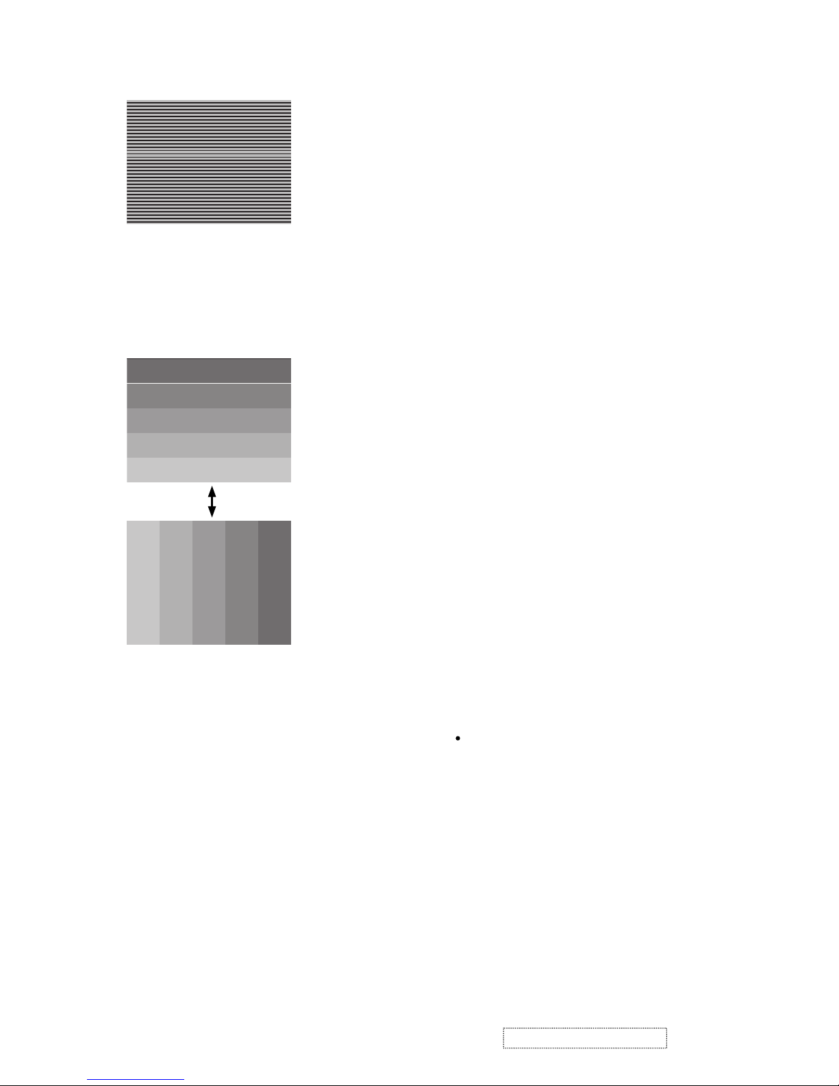
4-6
NRSH adjustment (vertical stripe adjustment)
Signals for internal adjustment
64
/255
88
/255
112
/255
136
/255
160
/255
160
/255
136
/255
112
/25588/25564/255
Adjustment procedure
1. Make this adjustment after completing the
adjustment in 4-5 Flicker adjustment.
2. Use DAC-P - NRSH - R: in the FACTORY
MENU to adjust so that the vertical lines spaced
every 6 dots are as inconspicuous as possible.
(Reduce the adjustment value when black
stripes appear in the 2nd or 3rd tone from the
black side. Note that when the adjustment value
is lowered, white stripes may appear in the 2nd
or 3rd tone from the bright side. Should this
happen, adjust so that the stripes are as inconspicuous as possible.)
3.
In the same way, use DAC-P - NRSH - G: in the
FACTORY MENU to adjust vertical stripes of G color.
4.
In the same way, use DAC-P - NRSH - B: in the
Adjustment menu to adjust vertical stripes of B color.
Press ENTER key
7
ViewSonic Corporation Confidential
-
Do Not Copy PJ452
VID-AD
MIN
MID-L
MID-H
MAX
DAC-P
GAMMA
C. UNIF.
No. 1 R 0
STRIPE
OPTION
C.UNIF
ON/OFF ON
OFF
G 0 B 0
Major adjustment lattice point No.
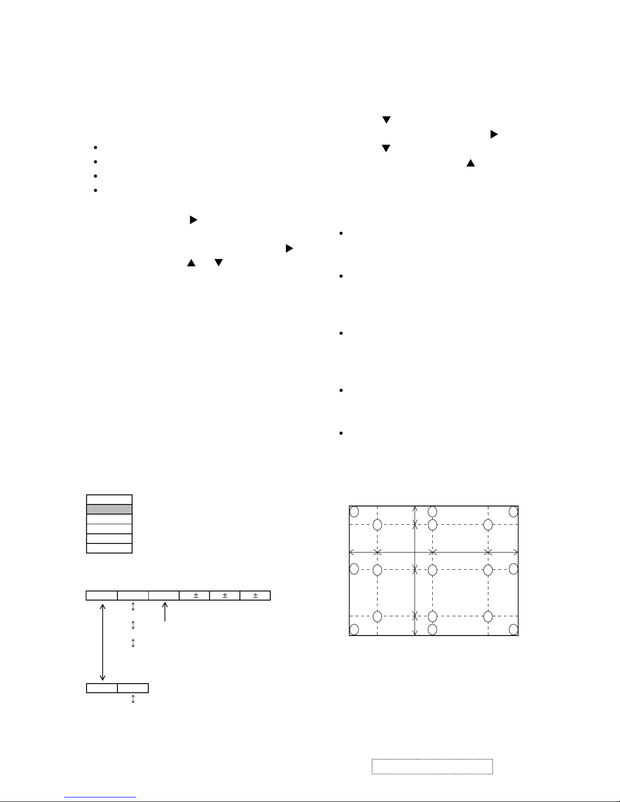
4-8 Color uniformity adjustment
Preparations
1.
Perform these adjustments after the white balance
adjustment described in Section 4-7.
2. Make a color uniformity adjustment for the follow-
ing four tones.
MIN tone (approx. 4% input signal)
MID-L tone (approx. 14% input signal)
MID-H tone (approx. 25% input signal)
MAX tone (approx. 57% input signal)
3. Place the cursor on [C.UNIF.] in the FACTORY
MENU and press the [ ] key. This displays the
Adjust Tone menu at the bottom of the screen.
To choose the tone to be adjusted, press the [ ]
key and then use the [ ] or [ ] key.
Select the major adjustment lattice point No.
and color, and then adjust them.
4. The major adjustment lattice point numbers (a
total of 17 points) corresponds to the major
adjustment lattice point positions in the diagram
on the right. The color uniformity of the entire
screen can be adjusted by adjusting the white
balance for each of the points starting in order
from the low numbers.
5. Adjustment point No.1 should not be adjusted,
because it controls the brightness of the entire
screen.
6.
To temporarily turn correction off, place the
cursor on [C.UNIF.] in the Adjust Tone menu and
press the [
] key. The ON/OFF menu appears.
Place the cursor on [ON] with the [ ] key and
press the [ ] key. To turn it on again, place the
cursor on [OFF] and press the [ ] key.
7. Although this adjustment can also be made
using internal signals, we will here use the
[ENTER] key on the Remote control transmitter
to select the following two signals.
Solid monochrome adjustment color (use G
color adjustment when a color differential
meter is used).
Solid white (use for adjustment other than
above).
8. Reset color-shading correction before adjust-
ment.
When 4 tones and all colors are to be reset,
place the cursor on [C.UNIF.] in the FACTORY
MENU, press the [RESET] key and select
[DEFAULT].
When only 1 tone is to be reset, place the
cursor on the tone to be reset, press the
[RESET] key and select [DEFAULT].
Single tone and monochrome resets cannot
be performed.
FACTORY MENU
Major adjustment lattice point position
14 12
13
16
15 17
6 4 8
2 1 3
7 5 9
10 11
V/6
H/6 H/3 H/3 H/6
V/3
V/3
V/6
Adjust tone menu
8
ViewSonic Corporation Confidential
-
Do Not Copy PJ452

Adjustment procedure 1
(When a color differential meter is used)
1. First adjust [MID-L] tone [G:].
2. Select adjustment point [No.2][G:].
When the background is not [G] monochrome,
press the [ENTER] key on the Remote control
transmitter to change to solid [G] monochrome.
3. Measure the illumination at adjustment points
No. 2, No.3, No.10 and No.11.
The values should be:
No.2 = Y2 [lx] No.10 = Y10 [lx]
No.3 = Y3 [lx] No.11 = Y11 [lx]
4. No.2 and No.3 adjustment point have the aver-
age of Y2 and Y3.
Y2 = ( Y2 + Y3 ) / 2 ± 2 [%]
Y3 = ( Y2 + Y3 ) / 2 ± 2 [%]
5. No.10 and No.11 adjustment point have the
average of Y10 and Y11.
Y10 = ( Y10 + Y11 ) / 2 ± 2 [%]
Y11 = ( Y10 + Y11 ) / 2 ± 2 [%]
6. Then adjust [MID-L] tone [R] and [B].
When the background is [G] monochrome,
press the [ENTER] key on the Remote control
transmitter to change to solid white.
7. Measure the color coordinates of adjustment
point [No.1] and make a note of them.
Assume that they are x = x1, y = y1.
Note: When the CL-100 color and color differ-
ence meter is used, the [ ∆ ](delta) mode
is convenient. When adjustment point
[No.1] color coordinate has been
selected, set the slide switch on the side
to [∆](delta) while holding down the [F]
button on the front panel. The measure-
ment shown after this displays the devia-
tion from measurement point 1.
8. Measure the color coordinates of measurement
point [No.2] and adjust [No.2][R:] and [B:] so
that the coordinates are as follows.
x = x1 ± 0.005 , y = y1 ± 0.010
9. Similarly, measure adjustment points [No.3] to
[No.17] and adjust their color coordinates start-
ing in order from the small number points.
This completes adjustments required for [MIN].
Note: Since excessive correction may lead to a
correction data overview during internal
calculations, use the following values for
reference.
[No.2] to [No.5] ± 40 or less
[No.6] to [No.9] ± 50 or less
[No.10] to [No.13] ± 70 or less
[No.14] to [No.17] ± 120 or less
10. Then adjust [MIN] tone [G] so that the adjust-
ment data set two times as much as [MID-L]
tone [G].
This completes [G] color adjustments.
11. Then adjust [MIN] tone [R] and [B].
Select [No.2] [B:] and press the [ENTER] key
on the Remote control transmitter to change to
solid white.
12. Measure the color coordinates of adjustment
point [No.1] and make a note of them.
Assume that they are x = x1, y = y1.
13. Now measure the color coordinates of mea-
surement point [No.2] and adjust [No.2][R:] and
[B:] so that the coordinates are as follows.
x = x1 ± 0.005 , y = y1 ± 0.010 (Target)
x = x1 ± 0.020 , y = y1 ± 0.040
14. Similarly, measure adjustment points [No.3] to
[No.17] and adjust their color coordinates start-
ing in order from the small number points.
This completes [MIN] tone adjustments.
15. Now make similar adjustments for [MID-H] tone.
(Adjust [MID-H] tone [G] so that the adjustment
data set half as many as [MID-L] tone [G].)
16. Now make similar adjustments for [MAX] tone.
(Adjust [MAX] tone [G] so that the adjustment
data set half as many as [MID-L] tone [G].)
9
ViewSonic Corporation Confidential
-
Do Not Copy PJ452
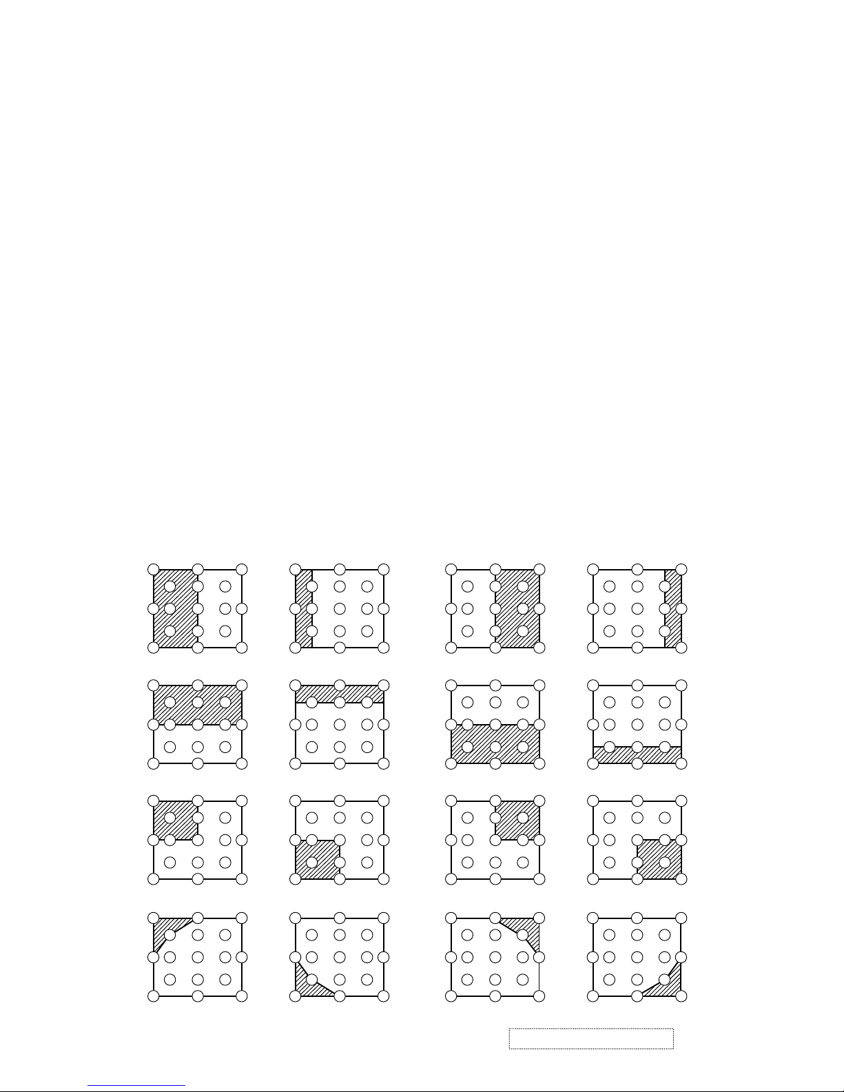
Adjustment procedure 2
(visual inspection)
1. First adjust [MIN] tone [G:].
2. Select [No.2] [G:].
If the background is [G] monochrome, press the
[ENTER] key on the Remote control transmitter
to change to solid white.
3. View measurement point [No.2] and [No.3].
Lower the [G] color intensity only of the color
point whose [G] color is more intense than
measurement point [No.1].
4. View measurement point [No.10] and [No.11].
Lower the [G] color intensity only of the color
point whose [G] color is more intense than
measurement point [No.1], and raise the inten-
sity of the point whose color intensity is lower
than measurement point [No.1].
5. Now adjust the [MIN] tone for colors [R] and [B].
6. View measurement points [No.2], [No.3],
[No.10] and [No.11]. Adjust the [R] and [B] of
each measurement point so that they have the
same color as measurement point [No.1].
Adjustment technique:
First, adjust [B:] of the point whose color is to
be adjusted so that it approximates that of
[No.1]. If [R:] is low at this time, the image will
have cyan cast, in which case [R:] is increased.
On the other hand, if [R:] is excessive, the
image will have a magenta cast, in which case
[R:] is decreased.
Overall, a cyan cast makes it easy to see color
shading.
7. Next, view measurement points [No.4], [No.5],
[No.12], [No.13] and make similar adjustments.
8.
Then adjust measurement points [No.6], [No.7],
[No.8], [No.9], [No.14], [No.15], [No.16] and [No.17].
This completes the [MIN] tone adjustments.
9. Make similar another three tones as described
in steps 1 to 8 above.
8
3
16
17
9
11
6
14
2
12
15
13
10
7
4
1
5
8
3
16
17
9
11
14
12
15
13
10
4
1
5
6
2
7
8
3
16
17
9
11
6
2
12
13
14
15
10
7
4
1
5
14
12
15
13
10
4
1
5
6
2
7
8
3
16
17
9
11
17
9
15
13
7
5
3
17
9
11
15
13
10
1
5
6
2
7
8
16
17
9
6
12
13
7
4
5
14
12
10
4
1
6
2
8
3
16
17
9
11
3
11
2
10
1
16
14
12
8
6
4
8
4
16
14
12
3
11
2
14
15
10
1
5
7
15
13
17
9
15
13
7
5
3
17
9
11
6
17
9
6
13
7
5
14
12
10
4
6
2
8
16
3 11
2
10
1
16
14
12
8
6
4
8
4
16
14
12
3
11
2
14
15
10
5
7
15
10
1
2
13
15
5
7
12
4
1
8
17
13
1
3
11
16
95
17
9
15
13
7
5
3
17
9
11
6
17
9
6
13
7
5
14
12
10
4
6
2
8
16
3
11
2
1
16
14
12
8
4
8
4
16
14
12
3
2
14
15
10
5
7
15
10
1
2
13
5
7
12
4
1
17
13
1
3
5
11
9
11
8
16
15
10
6
No. 2 deviation range No. 10 deviation range No. 3 deviation range No. 11 deviation range
No. 4 deviation range No. 12 deviation range No. 5 deviation range No. 13 deviation range
No. 6 deviation range No. 7 deviation range No. 8 deviation range No. 9 deviation range
No. 14 deviation range No. 15 deviation range No. 16 deviation range No. 17 deviation range
ViewSonic Corporation Confidential
-
Do Not Copy PJ452
10
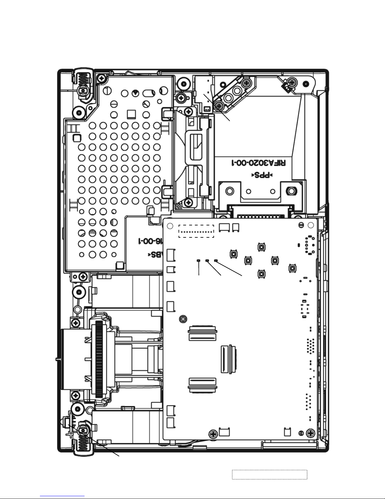
5. Troubleshooting
Check points
PWB Assembly SW
E800
E803
ESPL
E801
E804
E301
E802
D303
(LAMP)
D302
(TEMP)
D301
(Power)
P501
P701
P601
E806
E302
E807
E805
PWB assembly MAIN
PWB assembly REMOTE
*Top view of the projector after the silver gilding on the lamp house detached.
ViewSonic Corporation Confidential
-
Do Not Copy PJ452
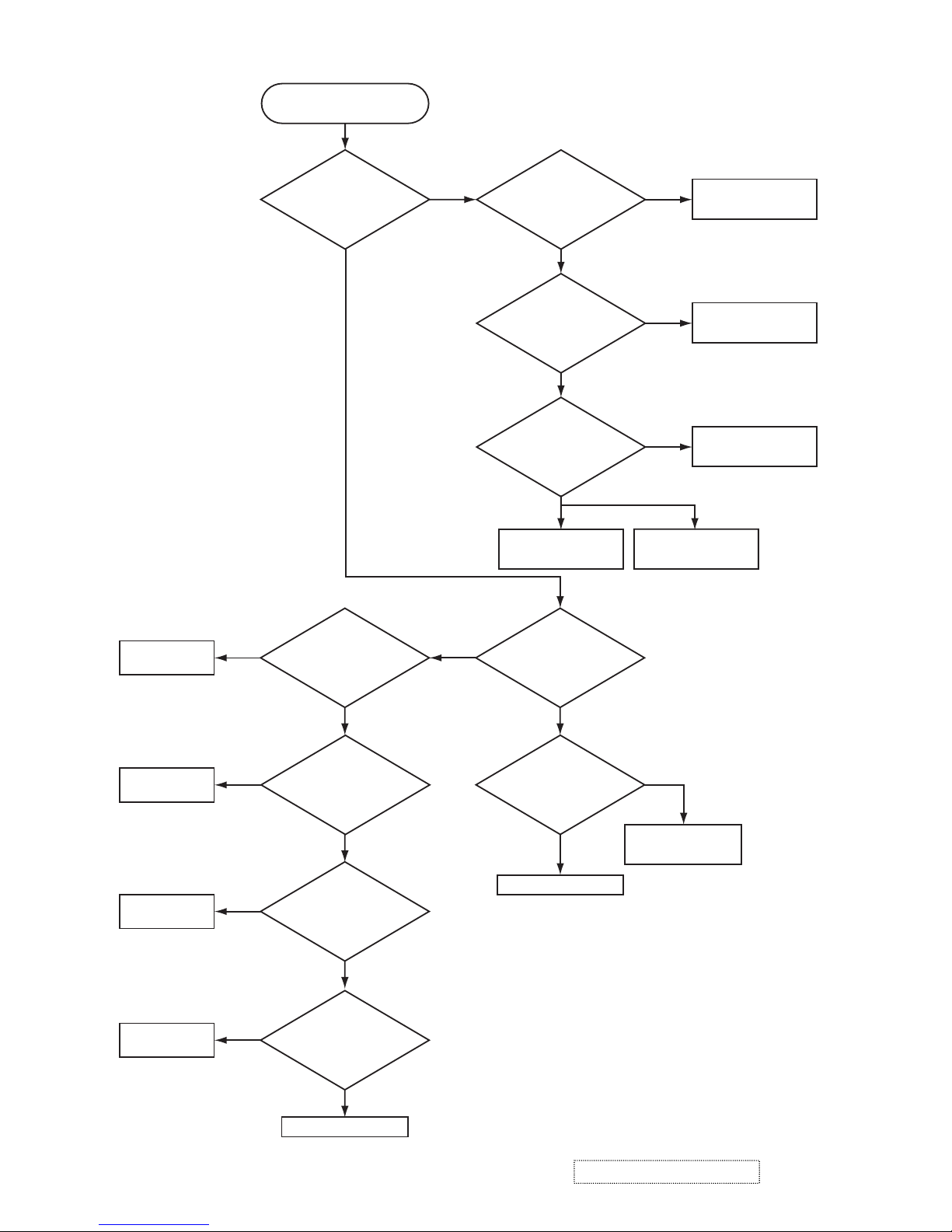
11
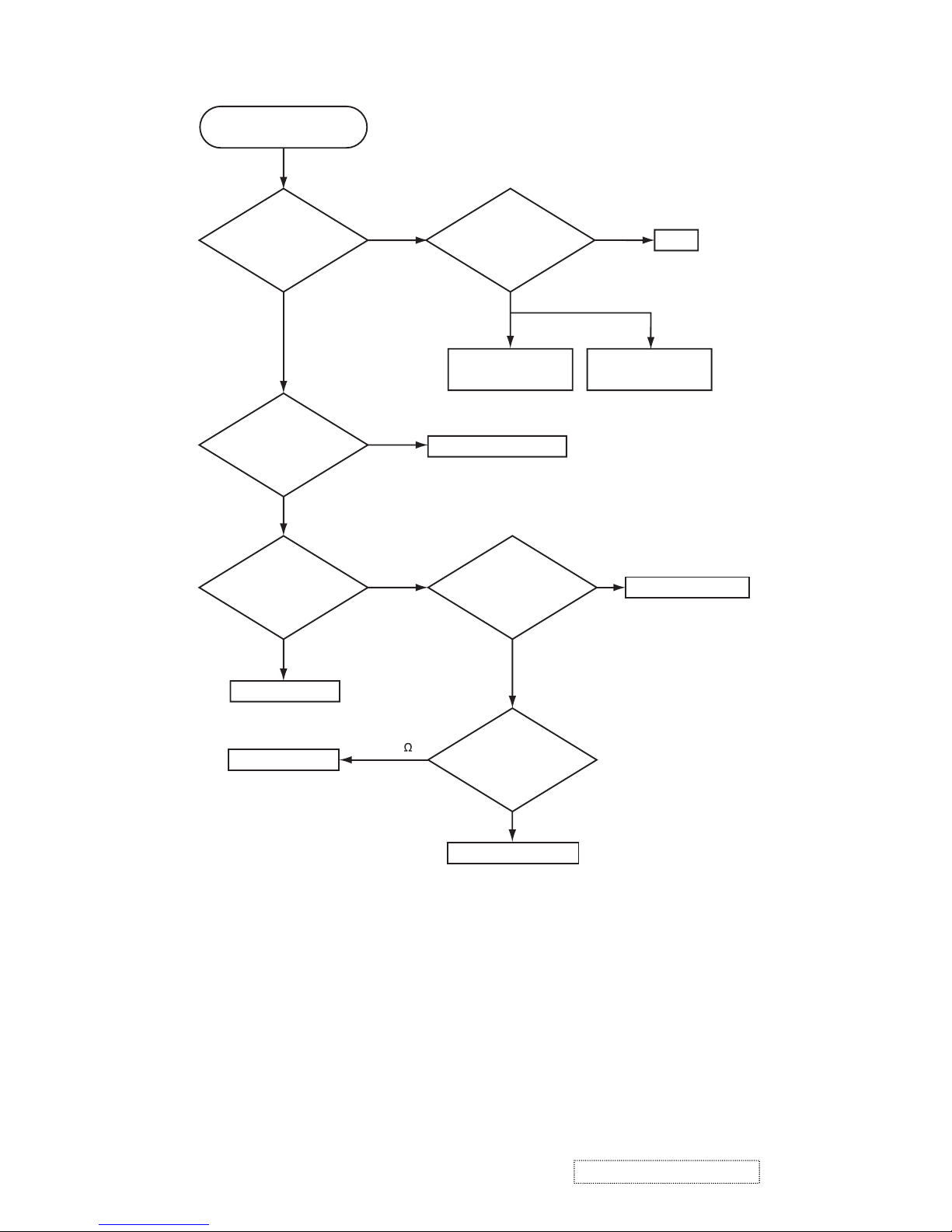
Power can not be turned on
Are
voltage input at
pins (1)(3)(5)(7) of E800
on the PWB assembly
Main at standby
mode?
(1): +0V
(3): +17V
(5): +6.6V
(7): +4.1V
Power unit (circuit)
Fuse on the
Power unit (circuit)
NO
YES
Disconnect
TSW form Power unit
(circuit). And check
TSW short or
open?
PWB assembly Main
Short
TSW
Open
What is the state of
TEMP indicator D302?
Not light
Blinks
Jump to * on the page 13
What is the state of
LAMP indicator D303?
Not light
Blinks
Short (0 )
Unplug
power cord and
disconnect cable CNLC,
then measure resistance
between pins (1)
and (2) of
CNLC.
Open
PWB assembly Limit SW
PWB assembly Main
Is the LAMP DOOR
set?
OK
Set the LAMP DOOR
NG
ViewSonic Corporation Confidential
-
Do Not Copy PJ452
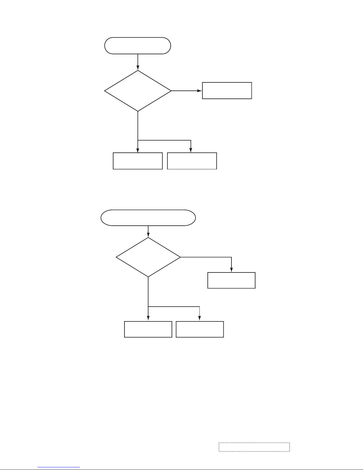
12
Lamp does not light
What is the
state of LAMP indicator
D303 during operation?
Power unit (ballast)
Lamp
PWB assembly MAIN
Power unit (ballast)
Light
PWB assembly MAIN
YES
Not light
NO
YES
Change the lamp.
Does lamp light?
Power unit (circuit)
Not light
Install the Lamp
Light NG
Is the LAMP
installation correct?
YES
NO
What is the state
of TEMP indicator D302?
Not light
Blinks
DC FAN
(Exhaust)
H (3.3V)
"L" = 0V
L (0V)
L (0V)
Is the
voltage at the
(1) of E804 on the PWB
assembly MAIN fixed to "L"
during warming-up?
"L" = 0V
Measure
voltage at pin(1)
of E801 on PWB
assembly MAIN.
DC FAN
(B Panel)
Measure
voltage at pin(1)
of E807 on PWB
assembly MAIN.
Is the voltage
at the (3) of E804 on
the PWB assembly MAIN
set to "L" during
warming-up?
DC FAN
(Sub)
NO
YES
(L=0V)
Is the
voltage at the pin
(1) of E806 on the PWB
assembly MAIN set
to “L” ?
*
H (3.3V)
DC FAN
(R/G Panel)
L (0V)
Measure
voltage at pin(1)
of E802 on PWB
assembly MAIN.
PWB assembly MAIN
H (3.3V)
ViewSonic Corporation Confidential
-
Do Not Copy PJ452
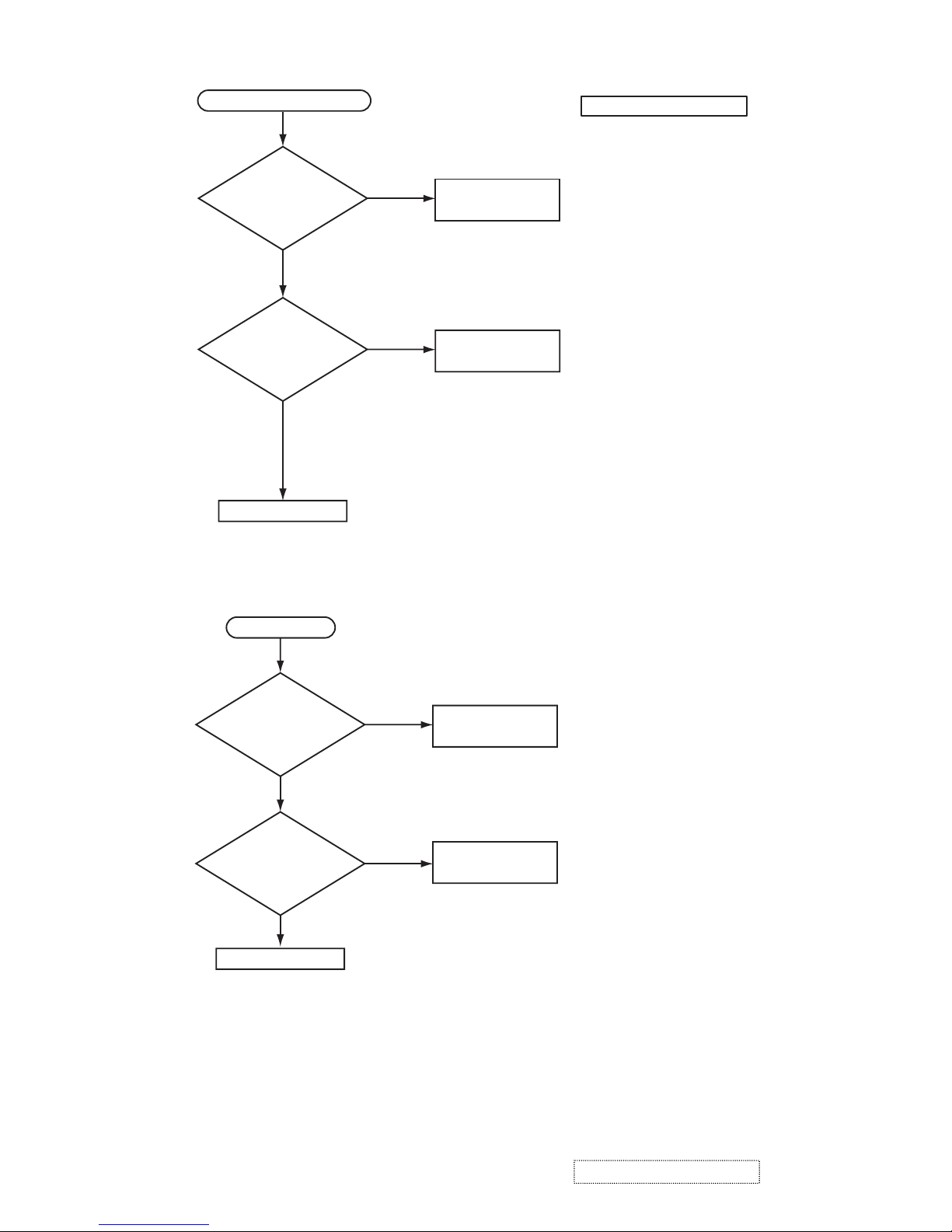
13
Picture is not displayed only
when the RGB signal is input
PWB assembly M
AIN
LCD PRISM
assembly
Check at operating mode
Power unit
(circuit)
NO
YES
Are
voltage input
at pins(1)(3)(5)(7) of
E800 on the PWB
assembly
MAIN?
(1):+13.2V
(3):+17V
(5):+6.6V
(7):+4.1V
Power unit (circuit)
NO
YES
Are
voltage input at
pins(1)(3)(5)(7) of E800
on the PWB assembly
MAIN?
(1): +13.2V
(3): +17V
(5): +6.6V
(7): +4.1V
PWB assembly MAIN
LCD PRISM
assembly
Check at operating mode
Picture is not displayed only when the
VIDEO, S-VIDEO signal is input
ViewSonic Corporation Confidential
-
Do Not Copy PJ452
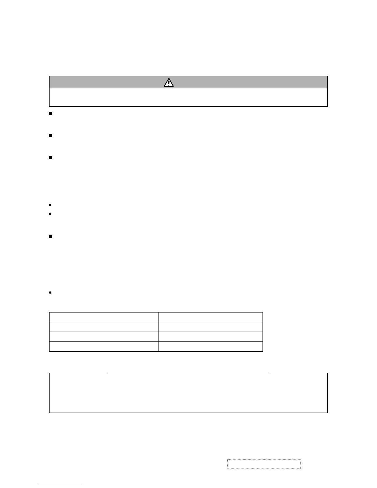
14
The check after parts change
1. PC power supply OFF
2. Connection of cable
3. Projector starting
4. PC starting
*When not operating :
PC set up change of cable.
Can not control to RS-232C
PWB assembly MAIN
NO
NO
YES
Use cross cable
Check the
RS-232C cable.
Are pin No. 2 and 3
crossed?
YES
Power unit (circuit)
Check the
power supply voltage
of E800 the voltage
correct?
(1): +13.2V
(3): +17V
(5): +6.6V
(7): +4.1V
Speaker
No sound
NO
YES
Power unit (CIRCUIT)
Are
voltage input at pin
(1)(3)(5)(7) of the E800 on
the PWB assembly
MAIN?
about 8Ω
0Ω or infinity
PWB assembly MAIN
Turn off
the projector and
disconnect the Speaker
cable from ESPL.Measure
the resistance of
the Speaker
.
(1): +13.2V
(3): +17V
(5): +6.6V
(7): +4.1V
ViewSonic Corporation Confidential
-
Do Not Copy PJ452
15
6. Service points
6-1 Lead free solder [CAUTION]
This product uses lead free solder (unleaded) to help preserve the environment. Please read these
instructions before attempting any soldering work.
Lead free solder indicator
Printed circuit boards using lead free solder are engraved with an "F" or "LF".
Properties of lead free solder
The melting point of lead free solder is 40-50˚C higher than leaded solder.
Servicing solder
Solder with an alloy composition of Sn-3.0Ag-0.5Cu or Sn-0.7Cu is recommended.
Although servicing with leaded solder is possible, there are a few precautions that have to be taken. (Not
taking these precautions may cause the solder to not harden properly, and lead to consequent malfunctions.)
Precautions when using leaded solder
Remove all lead free solder from soldered joints when replacing components.
If leaded solder should be added to existing lead free joints, mix in the leaded solder thoroughly after the
lead free solder has been completely melted (do not apply the soldering iron without solder).
Servicing soldering iron
A soldering iron with a temperature setting capability (temperature control function) is recommended.
The melting point of lead free solder is higher than leaded solder. Use a soldering iron that maintains a high
stable temperature (large heat capacity), and that allows temperature adjustment according to the part being
serviced, to avoid poor servicing performance.
Recommended soldering iron:
Soldering iron with temperature control function (temperature range: 320-450˚C)
Recommended temperature range per part:
Part Soldering iron temperature
Mounting (chips) on mounted PCB 320˚C±30˚C
Mounting (chips) on empty PCB 380˚C±30˚C
Chassis, metallic shield, etc. 420˚C±30˚C
(1) PWB assembly MAIN
(2) PWB assembly REMC
(3) PWB assembly SW
(4) POWER UNIT (BALLAST)
(5) POWER UNIT (CIRCUIT)
The PWB assembly which has used lead free solder
CAUTION
Always wear safety glasses to prevent fumes or molten solder from getting into the eyes. Lead free solder
can splatter at high temperatures (600˚C).
ViewSonic Corporation Confidential
-
Do Not Copy PJ452
16
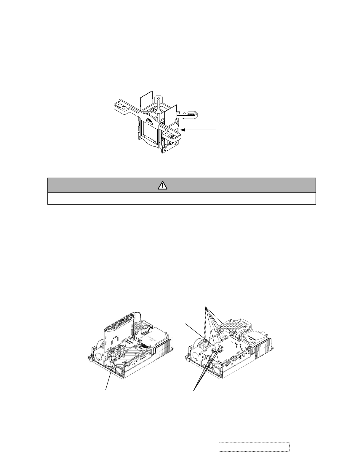
6-2 Replacing The LCD/PRISM assembly
You should not replace separately the parts of the LCD/PRISM assembly. In case of a failure in any parts of
LCD/PRISM assembly, replace the whole LCD/PRISM assembly.
Do not disassemble the unit
becaouse replacement of separate
parts is not possible.
LCD/PRISM ASSY
6-3 Cleaning up dust from panels and optical filters
1. Preparation
Please prepare cleaning tools and materials as follows. And prepare relatively clean room not to work in
additional dust, while removing operation.
(1) Swab for cleaning "Cotton stick L147"
(2) Air duster (Dust blower, spray can)
(3) Vacuum cleaner
2. Disassemble and open the maintenance hole.
(1) Turn off the projector, and unplug the power cord.
(2) Remove the top cover, according to the notice 1 of chapter 8.
(3) Remove the PWB assembly MAIN, according to the notice-2 of the chapter 8.
(4) Remove the Panel Cover.
(5) Attach the PWB assembly MAIN in original place, and connect cables indicated above. Note that flexi-
ble cables of LCD panels should come to the upper portion of PWB assembly MAIN, but don’t connect them to the connectors. Make sure that flexible cables’ terminals don’t touch to any other parts
during maintenance, especially when the projector is turned on.
WARNING
Wear sunglasses to protect your eyes when you maintain the projector with its lamp on.
Flexible cables of LCD panels
Remove Panel Cover
PWB assembly MAIN
Connect cables
ViewSonic Corporation Confidential
-
Do Not Copy PJ452
17
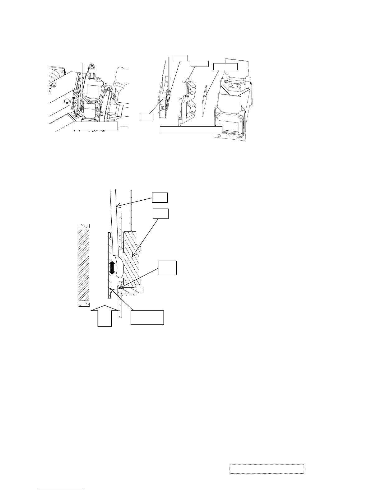
3. Maintenance point
Each color part has same
construction.
By using swab and air duster,
you can easily remove dust
from panel and optical filter.
4. Cleaning the panels and optical filters
(1) Turn on the set and lit on the lamp.
(2) By using swab and air duster, remove the dust. Focusing dust makes you check the dust on screen.
• While removing the dust, separated dust
will be blown off by air cooling system.
• Please pay attention not to damage panel
and optical filter.
5. Re-assembly
(1) Turn off the set and remove the PWB assembly MAIN.
(2) Set the
Panel cover
.
(3) Re-assemble the PWB assembly MAIN.
(4) Re-assemble the set.
(5)
While re-assembling, please clean the Panel cover and intake filter and filter cover by using vacuum cleaner.
Swab
Panel
Optical filter
Holder
Air
Actual formation
Swab
Panel
Holder
Optical filter
Separatied formation
ViewSonic Corporation Confidential
-
Do Not Copy PJ452
18
 Loading...