

Page 1

Service Manual
ViewSonic VP171s/b-2
Model No.VLCDS25972-4W/5W
17” Color TFT LCD Display
ViewSonic
( VP171s/b-2_SM_947-Rev. 1a– Dec. 2004 )
381 Brea Canyon Road, Walnut, California 91789 USA - (800) 888-8583
Page 2
Copyright
Copyright
2004 by ViewSonic Corporation. All rights reserved. No part of this publication may be
¤
reproduced, transmitted, transcribed, stored in a retrieval system, or translated into any language or
computer language, in any form or by any means, electronic, mechanical, magnetic, optical, chemical,
manual or otherwise, without the prior written permission of ViewSonic Corporation.
Disclaimer
ViewSonic makes no representations or warranties, either expressed or implied, with respect to the
contents hereof and specifically disclaims any warranty of merchantability or fitness for any particular
purpose. Further, ViewSonic reserves the right to revise this publication and to make changes from time
to time in the contents hereof without obligation of ViewSonic to notify any person of such revision or
changes.
Trademarks
Optiquest is a registered trademark of ViewSonic Corporation.
ViewSonic is a registered trademark of ViewSonic Corporation.
All other trademarks used within this document are the property of their respective owners.
Revision History
1a
12/08/04
Documents Number
DCN Number ECR Number
4870
Description of Changes EditorRevision SM Editing Date
Initial Release
A. Lu
ViewSonic Corporation Confidential
i
-
Do Not Copy VP171s/b-2
Page 3

Preface
This manual is prepared for the maintenance service for the VP171/s/b series LCD
Panel Monitor. Maintenance procedures described in this manual are intended to isolate
faulty parts and replace them in the field. It also aims to serve as a guide in procuring
replacement parts for this product.
This manual is copyrighted and all rights are reserved. This product may not,
in whole or in part be copied, photocopied, translated or reduced to any electronic or
machine readable form without prior written consent except for copyies retained by
the purchaser for backup purpose.
This manual includes system overview, major system assembly, components
description, and the Troubleshooting makes explanations on how to detect errors.
It also includes a flow chart for checking or correcting faults.
No Warranty or representation, either expressed or implied, is made with
respect to this documentation, its quality, performance, merchantability or
fitness for particular purpose.
No event will the vendor be liable for direct, indirect, special, incidental or
consequential damages arising out of the user or inability to use this product
or documentation.
Notice:
The information found in this manual is subject to change without prior notice. Any
subsequent changes made to the data herein will be incorporated in future edition.
ViewSonic Corporation Confidential
ii
-
Do Not Copy VP171s/b-2
Page 4

TABLE OF CONTENTS
1 Introduction
2 Mechanical Construction
3 Procedure of Disassembly
4 Troubleshooting Procedure
5Function Test & Alignment Procedure
6 Firmware Upgrade Procedure
7 DDC Key In Procedure
8 Panel Specification
9 Packing For Shipping
10 Appendix
11PCB Layout
12Schematic Diagrams
13 Recommended Spare Parts List
1
4
8
17
21
30
39
44
50
52
61
63
72
ViewSonic Corporation Confidential
iii
-
Do Not Copy VP171s/b-2
Page 5

1. Introduction
This manual provides the integral information you need to maintain the LCD Monitor, and
the manual is applied to the mode of 1280*1024 resolution and 17 SXGA TFT LCD Monitor.
There are ten topics in this manual, and you can immediately identify problems through the manual.
This manual is for the technicans and people with an electronics background.
Send the product back to the distributor for repairing and do not attempt to do
is complex or isnt mentioned in the
Troubleshooting.
1-1 The Appropriate Operation
- Turn off the product before cleaning.
- Use only a dry soft cloth when cleaning the LCD panel surface.
- Use a soft cloth moistured with mild detergent to clean the display housing.
- Disconnect the power plug from AC outlet if the product is not used for
a long period of time.
-Do not touch the LCD panel surface with sharp or hard objects.
- Do not use abrasive cleaners, waxes or solvents for your cleaning.
- Do not operate the product under the following conditions :
1.) Extremely hot, cold or humid environment.
2.) Areas susceptible to excessive dust and dirt.
3.) Near any appliance generating a strong magnetic field.
4.) Place in direct sunlight.
anything which
1-2 Product Highlight
- Dual Analog and Digital Signal Input
- Active matrix TFT LCD Technology
- 1280*1024 addressable pixels
- 30-82kHz Horizontal Frequency
- 50-85Hz V ertical Refresh Rate
- Wide Viewing Angle Technology
- Auto-Adjustment
- Multifunction OSD User Controls
- VESA DPMS Power Saving
- High quality full screen re-scaling capability
ViewSonic Corporation Confidential
1
-
Do Not Copy VP171s/b-2
Page 6

1-3 Technical Specification
LCD T e chnology
Fisrt Source
-Source panel AU Panel (M170EG01 V2)
-Size 17” diagonal screen size
-Type MVA type with L VDS interface
-Pixel 1280*1024 addressable pixels
-Pixel Pitch 0.264mm*0.264mm pixel pitch
-Brightness 300 cd/m2 (Typ after 30 minute warm up)
-Contrast Ratio 500:1 (Typ), 300:1 (M in)
-Viewing Angle(Horizontal) 140 deg @ CR>10
-Viewing Angle (V ertical) 130 deg @ CR>10
-Response Time 8 ms (T r=6ms, Tf =2 ms) (T yp.)
-Backlight lamps 4 CCFL backlight lamps
-Backlight Life 50,000 Hours (Typ.) / 30,000 Hours (Min.)
Display Resolution -1280 pixels(H)*1024 lines(V)
Active Display Area -337.9mm(H)*270.3mm(V)
Displayable Color -16.2M Colors
Horizontal Scan -30 to 82kHz
Vertical Refresh -50 to 85 Hz
Max. Pixel Clock -135MHz
Auto-Adjustment -Yes
Re-Scaling -Yes
I/O Connectors -AC power in
-VGA in D-Sub 15 pin *2
-DVI-D Connector *1
Power Saving -VESA DPMS Signaling
Ergonomics -Tilt Up 25 degrees minimum
-Tilt Down 5 degrees
-Swivel Right 45 degrees
-Swivel Left 45 degrees
-Height Adjust 0~110 cm
-Pivot 0~90 degrees (Clockwise)
o
Environmental -Operating Te mperature: 0
~ +40oC/32o ~ 104oF
-Operating Relative Humidity: 20% ~ 90% RH Non-condensing
-Storage T emperature: -20o ~ +60oC/ -4o ~ 140oF
-Storage Relative Humidity: 5% ~ 90% RH Non-condensing
Mounting Interface -VESA Flat Panel Monitor Physical Mounting Interface
Power Supply -Internal Power Supply
-Power Dissipation : 50 Watts (typ.)
Dimension (W*H*D) -392.0mm*350.0mm*238.0mm
Weight -6.5 kgs/14.3 lbs
ViewSonic Corporation Confidential
2
-
Do Not Copy VP171s/b-2
Page 7
1-4 Compatible Modes
VP171 (AU Panel: M17EG01 V2):
ViewSonic Corporation Confidential
3
-
Do Not Copy VP171s/b-2
Page 8
2. Mechanical Construction
This section provides the package and exploded overview, replaceable parts list. You can
place an order for correct parts in the recommended parts list.
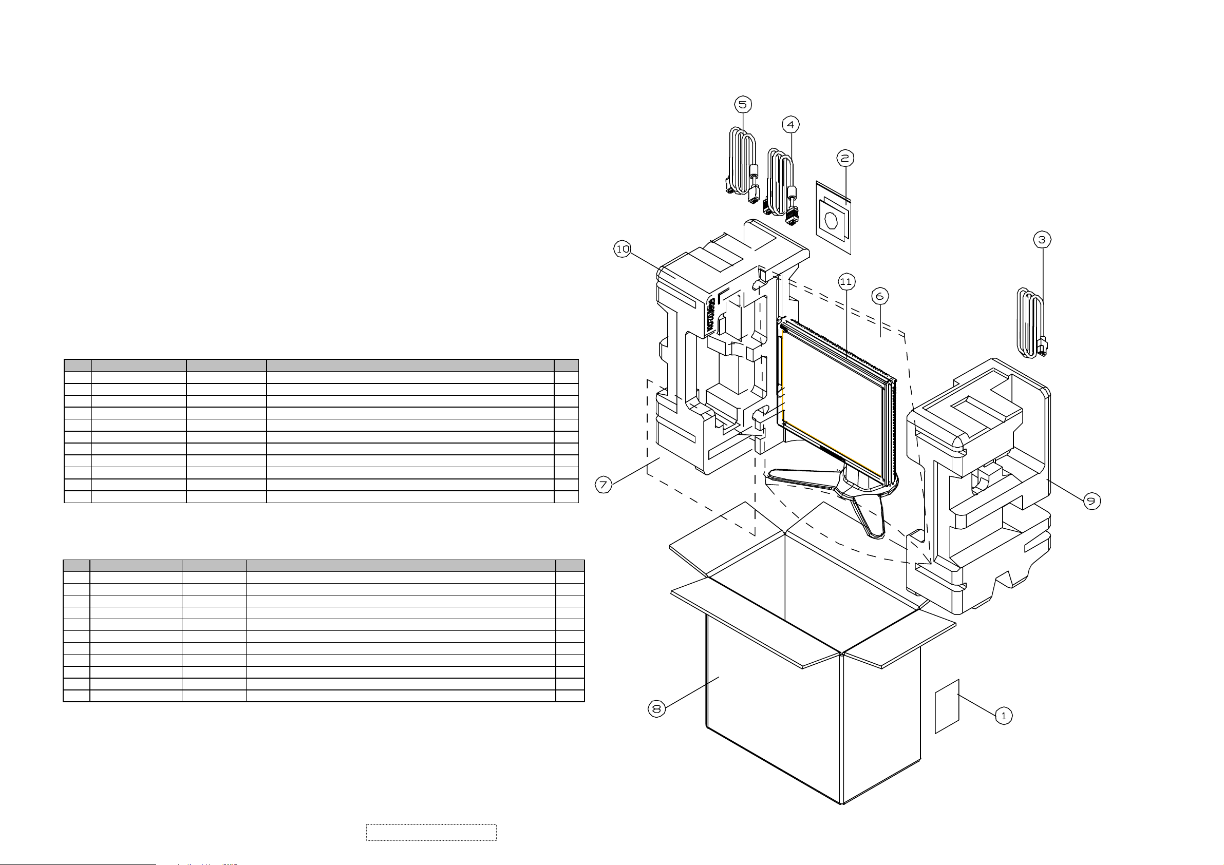
2-1 Package Overview
Item ViewSonic P/N Ref. P/N Description Q'ty
1 M-LB-0813-0706 35.58203.001 LABEL CARTON 76*76mm
2 DC-00000681 36.61102.003 USER GUIDE+CD VP171b AU EG01 V2
3 A-PC-0106-0272 42.50115.001 CABLE POWER CORD 1830mm SP30+IS14 1
4 A-VC-0101-0261 42.59901.A01 CABLE VGA 15P 1800mm 2*75mm 2-CORE 1
5 A-VC-0101-0262 42.59902.012 CABLE DVI-D 1.8M 2-CORE MOLEX
6 P-00000686 51.00081.009 PE BAG LDPE 570*850*0.1t W/HOLE 1
7 M-MS-0808-8952 51.58314.001 LCD PROTECT FILM 355*290*0.1t mm MYLAR VG700/VG750 1
8
9 P-FM-0602-0583 56.61101.001 CUSHION R EPS VP171
10 P-FM-0602-0584 56.61102.001 CUSHION L EPS VP171 1
11 VP171b-2 DC.61112.001 D.C. VP171b AUO M170 EG01 V2
P-00000683
PACKING PARTS LIST (VP171b-2)
1
1
1
55.61101.005 CARTON AB-18 465*265*430(h) VP171b 1
1
1
PACKING PARTS LIST (VP171s-2)
Item ViewSonic P/N Ref. P/N Description Q'ty
1 M-LB-0813-0706 35.58203.001 LABEL CARTON 76*76mm
2 DC-00000688 36.61101.004 USER GUIDE+CD VP171s AU EG01 V2
3 A-PC-0106-0272 42.50115.001 CABLE POWER CORD 1830mm SP30+IS14
4
5 A-VC-0101-0262 42.59902.012 CABLE DVI-D 1.8M 2-CORE MOLEX
6 P-00000334 51.00081.009 PE BAG LDPE 570*850*0.1t W/HOLE
7 M-MS-0808-8952 51.58314.001 LCD PROTECT FILM 355*290*0.1t mm MYLAR VG700/VG750
8 P-00000689 55.61101.006 CARTON AB-18 465*265*430(h) VP171s
9 P-FM-0602-0583 56.61101.001 CUSHION R EPS VP171
10 P-FM-0602-0584 56.61102.001 CUSHION L EPS VP171
11 VP171s-2 DC.61113.001 D.C. VP171s AUO M170 EG01 V2
A-VC-0101-0261
42.59910.A01 CABLE VGA 15P 1800mm 2*75mm 2-CORE
1
1
1
1
1
1
1
1
1
1
1
ViewSonic Corporation Confidential
4
-
Do Not Copy VP171s/b-2
Page 9
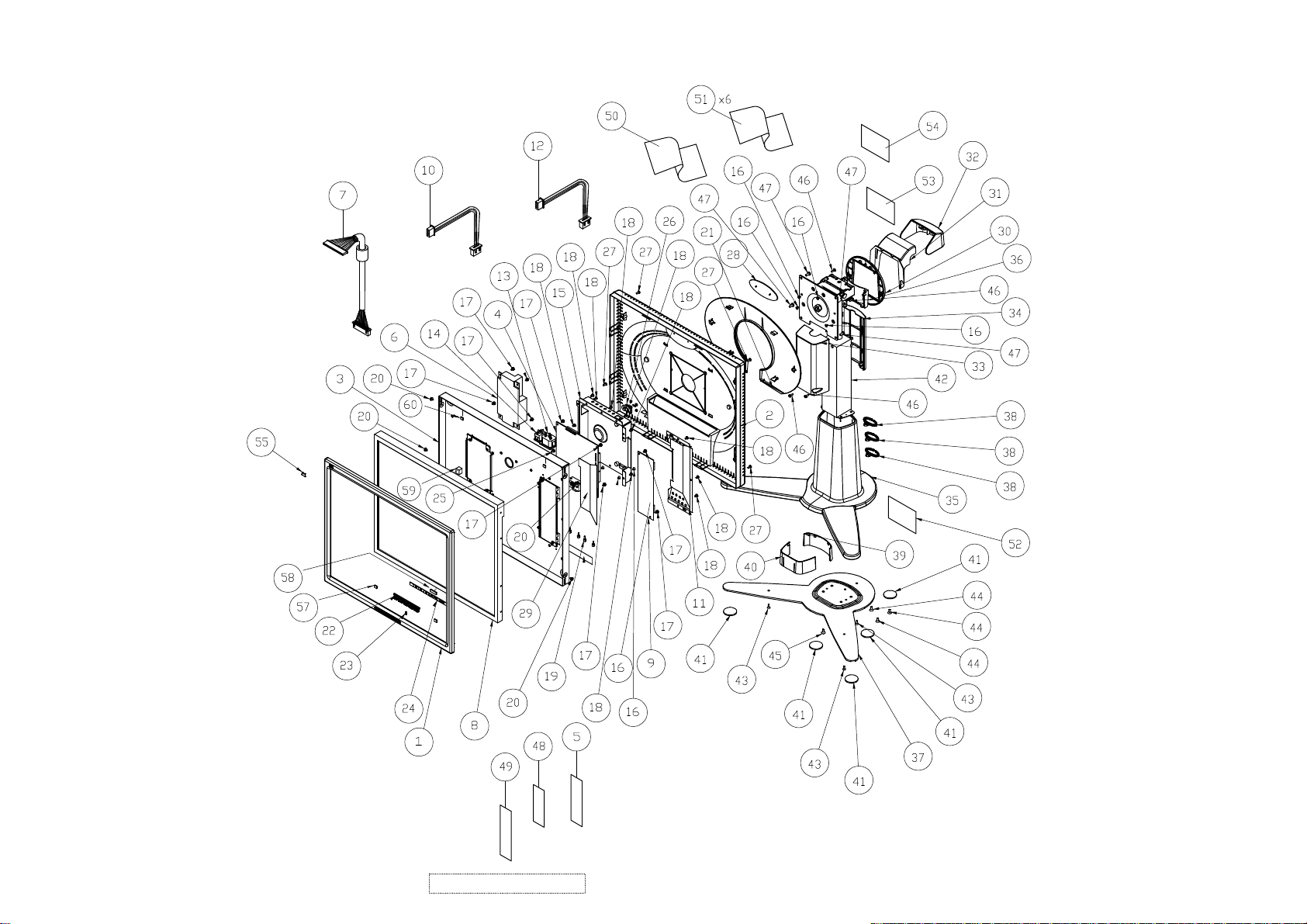
2-2 Exploded Overview
ViewSonic Corporation Confidential
5
56
-
Do Not Copy VP171s/b-2
Page 10

OPEN FRAME IN:100-240V OUT:12V/4.16A"LSE"(NOISE REDUCTION)
ViewSonic Model Number: VLCDS25972-4W
Rev: 1a
Item ViewSonic P/N Ref. P/N Description Q'ty
1 C-FP-0301-0373 51.61101.002 FRONT COVER PC+ABS-VS08A VP171b 1
2 C-BC-0302-0497 51.61102.002 REAR COVER PC+ABS-VS08A VP171b 1
3 HW-00000173 61.61101.002 LCD BRKT SECC 1.0t AUO M170EG01 VP171 1
4 B-00000677 80.61104.002 PCBA MAIN BD FOR VP171b AU EG01 V2 1
5 M-00000685 35.61204.002 COSMETIC STRIP ADHESIVE 180*10*0.3(t)mm PC- 1
6 B-PS-0204-0057 44.61103.003
7 CB-00000175 42.61103.A01 W.A. 30P UL20276 #28110mm W/O CORE VP171(COSTDOWN) 1
8 E-00000682 48.62701.006 TFT LCD 17" AUO M170EG01 V2 1
9 B-SB-0221-0700 44.58402.002 PCBA INVERTER;EMAX FOR 17" AUO M170EG01 V0 1
10 M-WR-0828-0717 42.61203.001 W.A. 4P UL1007 #24 250mm VP191(POWER) 1
11 PL-00000176 61.61102.001 SHIELDING PLATE-INV Tineplate 0.3t VP171 1
12 M-WR-0828-0716 42.61202.001 W.A. 10/6P UL1007 #24 50mm VP191(INV) 1
13 M-WR-0828-0718 42.61204.001 W.A. 4P UL1007 #18 VP191(SWT) 1
14 M-WR-0828-0719 42.61205.001 W.A. 3P UL1007 #18 50mm VP191(INLET) 1
15 M-MS-0808-9553 61.61202.001 SHIELDING BRKT-MB SECC 1.0t VP191 1
16 M-SCW-0824-6753 85.4A323.040 SCREW FLATE MECH M3*4 BLACK 7
17 M-SCW-0824-0651 85.1F123.060 SCREW PAN MECH W/SF M3*6 Ni 10
18 M-SCW-0824-6961 85.1H123.040 SCREW PAN MECH W/SPG M3*4 Ni 3
19 M-MS-0808-6287 85.005AG.075 SCREW HEX I/O #4-40*H5*L7.5 Ni NYLOK 6
20 HW-00000177 85.ZA123.040 SCREW WCH/W MECH M3*4 Ni 4
21 M-CV-0830-2426 51.61203.002 OVAL CAP PC+ABS-VS08A VP191b 1
22 PL-BT-0706-0134 51.61210.002 SELECT BUTTON PC+ABS-VS08 VP191b 1
23 M-MS-0808-9539 51.61211.001 LED LENS PMMA VP191 1
24 B-CB-0206-0158 80.61102.001 PCBA CTRL BD FOR VP171 1
25 M-SCW-0824-6827 85.1C124.060 SCREW PAN MECH W/T M4*6 Ni 1
26 M-BK-0805-0023 61.00042.001 LOCK BRKT+CAP SECC 0.8t 1
27 M-SCW-0824-6826 85.1F323.080 SCREW PAN MECH W/SF M3*8 BLACK 4
28 M-MS-0808-8299 51.58711.002 NAMEPLATE ELLIPSE CS-VS08 ViewSonic 1
29 M-MS-0808-8750 51.61103.001 MYLAR ADHESIVEt=0.3mm VP171 1
30 M-CV-0830-2427 51.61204.002 HINGE CAP-1 PC+ABS-VS08 VP191b 1
31 M-CV-0830-2428 51.61205.002 HINGE CAP-2 PC+ABS-VS08 VP191b 1
32 M-CV-0830-2429 51.61206.002 HINGE CAP-3 PC+ABS-VS08 VP191b 1
33 M-MS-0808-7823 51.61207.002 FRONT ARM PC+ABS-VS08 VP191b 1
34 M-MS-0808-7824 51.61208.002 REAR ARM PC+ABS-VS08 VP191b 1
35 M-CV-0830-2430 51.61209.002 BASE COVER PC+ABS-VS08 VP191b 1
36 M-CV-0830-2431 51.61212.002 HINGE CAP-4 PC+ABS-VS08 VP191b 1
37 M-MS-0808-8772 61.61204.001 BASE PLATE SPHC 3.0t Zn 1
38 PL-CL-0710-0033 51.61213.002 CLIP NYLON-VS08 VP191b 3
39 M-MS-0808-7795 51.61214.001 WEAR PLATE (FRONT) VP191 1
40 M-MS-0808-7796 51.61215.001 WEAR PLATE (REAR) VP191 1
41 PL-PD-0714-0091 52.61201.001 RUBBER PAD 27d*2t VP191 4
42 M-MS-0808-8756 61.61103.001 HINGE VP171 1
43 M-SCW-0824-0845 85.YA323.080 SCREW FLAT TAP M3*8 BLACK 3
44 M-SCW-0824-0869 85.4A624.080 SCREW FLAT MECH M4*8 BLACK NYLOK 4
45 M-SCW-0824-0868 85.4A623.080 SCREW FLAT MECH M3*8 BLACK NYLOK 1
46 M-SCW-0824-6755 85.UA123.080 DOUBLE THREADS SCREW PAN TAP M3*8 Ni 4
47 M-SCW-0824-0847 85.5A124.080 SCREW BINDING MECH M4*8 Ni 4
48 M-MS-0808-8797 51.00014.002 FILAMENT TAPE 3M NO.8915 25mm*55M 0.01
49 M-MS-0808-8239 51.59901.001 ACETATE TAPE W=20mm 10cm
50 M-MS-0808-7798 41.53615.001 EMI Tape (80560) 30*50mm 2
51 M-MS-0808-7799 41.54612.001 EMI Tape (80560) 25*30mm 5
52 M-LB-0813-0736 35.58304.001 LABEL BARCODE 40*14 ViewSonic 1
53 DC-00000680 35.61101.004 LABEL SPEC 120*50mm VP171b-4W 1
54 M-LB-0813-0781 35.61203.001 LABEL BAR CODE 50*25mm VP191 1
55 M-MS-0808-7800 35.61202.001 BIRD LOGO AL E015-004 "ViewSonic" 1
56 M-00000685 35.61204.002 COSMETIC STRIP ADHESIVE 180*10*0.3(t)mm PC- 1
57 PL-00000180 52.61101.001 RUBBER 20L*10W*2.0T VP171 2
58 M-MS-0808-9913 52.61202.003 RUBBER KIT SILICONE 20*10*7.0mm 1
59 M-MS-0808-9914 52.61202.002 RUBBER KIT SILICONE 20*10*3.5mm 1
60 PL-00000181 52.59907.005 RUBBER PAD 15*10*1.7t mm 2
EXPLODED PARTS LIST (VP171b-2)
1
ViewSonic Corporation Confidential
-
6
Do Not Copy VP171s/b-2
Page 11
ViewSonic Model Number: VLCDS25972-5W
Rev: 1a
Item ViewSonic P/N Ref. P/N Description Q'ty
1 C-FP-0301-0357 51.61101.003 FRONT COVER PC+ABS-VS07A VP171s 1
2 C-BC-0302-0508 51.61102.003 REAR COVER PC+ABS-VS06A VP171s 1
3 HW-00000173 61.61101.002 LCD BRKT SECC 1.0t AUO M170EG01 VP171 1
4 B-00000677 80.61104.002 PCBA MAIN BD FOR VP171b AU EG01 V2 1
5 M-00000174 35.61204.003 COSMETIC STRIP ADHESIVE 180*10*0.3(t)mm PC-VS06 VP191s 1
6 B-PS-0204-0057 44.61103.003 OPEN FRAME IN:100-240V OUT:12V/4.16A"LSE"(NOISE REDUCTION) 1
7 CB-00000175 42.61103.A01 W.A. 30P UL20276 #28110mm W/O CORE VP171(COSTDOWN) 1
8 E-00000682 48.62701.006 TFT LCD 17" AUO M170EG01 V2 1
9 B-SB-0221-0700 44.58402.002 PCBA INVERTER;EMAX FOR 17" AUO M170EG01 V0 1
10 M-WR-0828-0717 42.61203.001 W.A. 4P UL1007 #24 250mm VP191(POWER) 1
11 PL-00000176 61.61102.001 SHIELDING PLATE-INV Tineplate 0.3t VP171 1
12 M-WR-0828-0716 42.61202.001 W.A. 10/6P UL1007 #24 50mm VP191(INV) 1
13 M-WR-0828-0718 42.61204.001 W.A. 4P UL1007 #18 VP191(SWT) 1
14 M-WR-0828-0719 42.61205.001 W.A. 3P UL1007 #18 50mm VP191(INLET) 1
15 M-MS-0808-9553 61.61202.001 SHIELDING BRKT-MB SECC 1.0t VP191 1
16 M-SCW-0824-6753 85.4A323.040 SCREW FLATE MECH M3*4 BLACK 7
17 M-SCW-0824-0651 85.1F123.060 SCREW PAN MECH W/SF M3*6 Ni 10
18 M-SCW-0824-6961 85.1H123.040 SCREW PAN MECH W/SPG M3*4 Ni 3
19 M-MS-0808-6287 85.005AG.075 SCREW HEX I/O #4-40*H5*L7.5 Ni NYLOK 6
20 HW-00000177 85.ZA123.040 SCREW WCH/W MECH M3*4 Ni 4
21 M-CV-0830-2452 51.61203.003 OVAL CAP PC+ABS-VS06A VP191s 1
22 PL-BT-0706-0166 51.61210.003 SELECT BUTTON PC+ABS-VS07A VP191s 1
23 M-MS-0808-9539 51.61211.001 LED LENS PMMA VP191 1
24 B-CB-0206-0158 80.61102.001 PCBA CTRL BD FOR VP171 1
25 M-SCW-0824-6827 85.1C124.060 SCREW PAN MECH W/T M4*6 Ni 1
26 M-BK-0805-0023 61.00042.001 LOCK BRKT+CAP SECC 0.8t 1
27 M-SCW-0824-6826 85.1F323.080 SCREW PAN MECH W/SF M3*8 BLACK 4
28 M-MS-0808-8116 51.58711.001 NAMEPLATE ELLIPSE ViewSonic 1
29 M-MS-0808-8750 51.61103.001 MYLAR ADHESIVEt=0.3mm VP171 1
30 M-CV-0830-0297 51.61204.003 HINGE CAP-1 PC+ABS-VS06 VP191s 1
31 M-CV-0830-0298 51.61205.003 HINGE CAP-2 PC+ABS-VS06 VP191s 1
32 M-CV-0830-2453 51.61206.003 HINGE CAP-3 PC+ABS-VS06 VP191s 1
33 M-MS-0808-8751 51.61207.003 FRONT ARM PC+ABS-VS06 VP191s 1
34 M-MS-0808-8752 51.61208.003 REAR ARM PC+ABS-VS06 VP191s 1
35 M-CV-0830-2454 51.61209.003 BASE COVER PC+ABS-VS06 VP191s 1
36 M-CV-0830-2455 51.61212.003 HINGE CAP-4 PC+ABS-VS06 VP191s 1
37 M-MS-0808-8772 61.61204.001 BASE PLATE SPHC 3.0t Zn 1
38 M-MS-0808-8753 51.61213.003 CLIP NYLON-VS06 VP191s 3
39 M-MS-0808-7795 51.61214.001 WEAR PLATE (FRONT) VP191 1
40 M-MS-0808-7796 51.61215.001 WEAR PLATE (REAR) VP191 1
41 PL-PD-0714-0091 52.61201.001 RUBBER PAD 27d*2t VP191 4
42 M-MS-0808-8756 61.61103.001 HINGE VP171 1
43 M-SCW-0824-0845 85.YA323.080 SCREW FLAT TAP M3*8 BLACK 3
44 M-SCW-0824-0869 85.4A624.080 SCREW FLAT MECH M4*8 BLACK NYLOK 4
45 M-SCW-0824-0868 85.4A623.080 SCREW FLAT MECH M3*8 BLACK NYLOK 1
46 M-SCW-0824-6755 85.UA123.080 DOUBLE THREADS SCREW PAN TAP M3*8 Ni 4
47 M-SCW-0824-0847 85.5A124.080 SCREW BINDING MECH M4*8 Ni 4
48 M-MS-0808-8797 51.00014.002 FILAMENT TAPE 3M NO.8915 25mm*55M 0.01
49 M-MS-0808-8239 51.59901.001 ACETATE TAPE W=20mm 10cm
50 M-MS-0808-7798 41.53615.001 EMI Tape (80560) 30*50mm 2
51 M-MS-0808-7799 41.54612.001 EMI Tape (80560) 25*30mm 5
52 M-LB-0813-0736 35.58304.001 LABEL BARCODE 40*14 ViewSonic 1
53 DC-00000687 35.61101.005 LABEL SPEC 120*50mm VP171s-5W 1
54 M-LB-0813-0781 35.61203.001 LABEL BAR CODE 50*25mm VP191 1
55 M-MS-0808-7800 35.61202.001 BIRD LOGO AL E015-004 "ViewSonic" 1
56 M-00000174 35.61204.003 COSMETIC STRIP ADHESIVE 180*10*0.3(t)mm PC-VS06 VP191s 1
57 PL-00000180 52.61101.001 RUBBER 20L*10W*2.0T VP171 2
58 M-MS-0808-9913 52.61202.003 RUBBER KIT SILICONE 20*10*7.0mm 1
59 M-MS-0808-9914 52.61202.002 RUBBER KIT SILICONE 20*10*3.5mm 1
60 PL-00000181 52.59907.005 RUBBER PAD 15*10*1.7t mm 2
EXPLODED PART LIST (VP171s-2)
ViewSonic Corporation Confidential
7
-
Do Not Copy VP171s/b-2
Page 12
3. Procedure of Disassembly
This section provides disassembly procedures for VP171/s/b LCD Monitor. Before you begin
any of these procedures, be sure to turn off the power, computer system, and other attached
devices; then disconnect the power cable from the electronically outlet. Moreover, when you
disassemble the monitor, be sure to put the screws in a safe place and separate them according
to grouping.
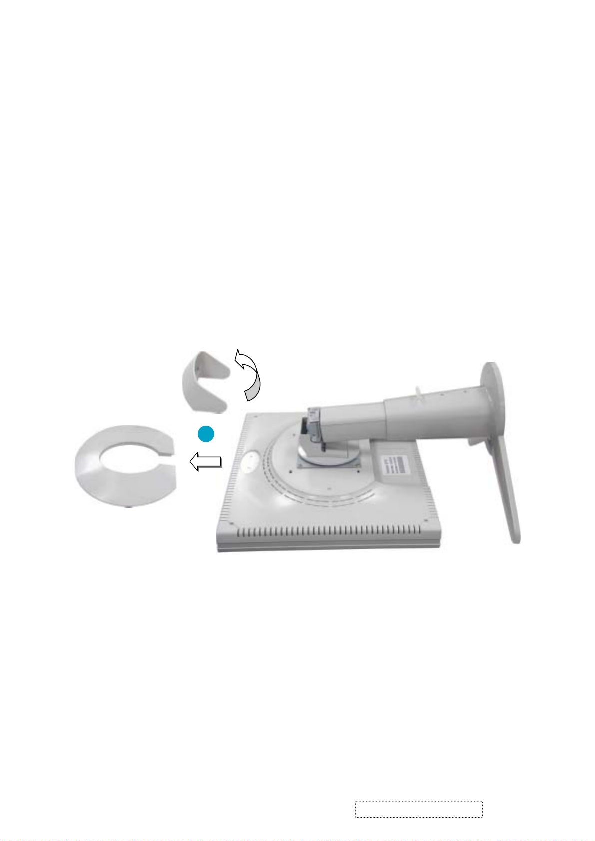
3-1 Disassembly of Stand unit from Monitor
Hinge Cap
Oval Cap
1
1. Put the monitor facedown. Take off Oval Cap and pry Hinge Cap off.
ViewSonic Corporation Confidential
8
-
Do Not Copy VP171s/b-2
Page 13

85.5A124.080
X 4
Stand unit
2. Unscrew five screws that secure Stand unit and detach Stand unit from the monitor.
2
85.4A123.080
X 1
3. Unscrew four screws of Base Plate to remove Hinge.
85.4A524.080
Base Plate
X 4
3
Hinge
ViewSonic Corporation Confidential
9
-
Do Not Copy VP171s/b-2
Page 14

85.YA323.080
Base Cover
X 3
4
Base Plate
4. Unscrew three screws that secure Base Plate to separate Base Plate from Base Cover.
Front Arm
Rear Arm
5
X 2
Hinge
5. Unscrew two screws that secure Rear Arm to separate Rear Arm from Hinge.
6. Turn Hinge and unscrew two screws that secure Front Arm to detach Front Arm from Hinge.
85.UA123.080
Hinge
6
X 2
85.UA123.080
ViewSonic Corporation Confidential
10
-
Do Not Copy VP171s/b-2
Page 15

3-2 Disassembly of Rear Cover
Rear Cover
LCD Panel Module
X 4
1
85.1F123.080
Rear Cover
1. Unscrew four screws of Rear Cover, then detach LCD Panel module from Rear Cover.
ViewSonic Corporation Confidential
11
-
Do Not Copy VP171s/b-2
Page 16
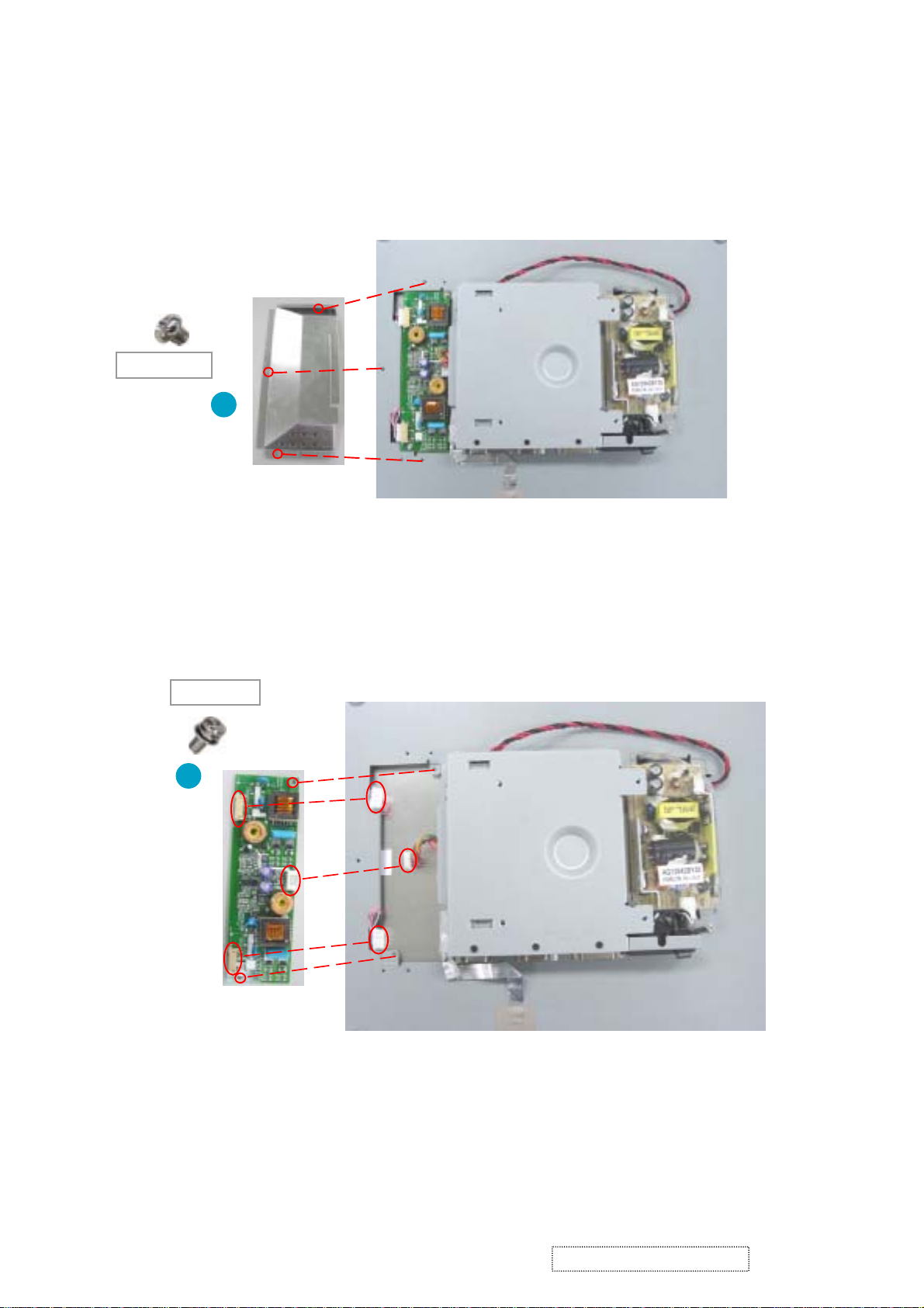
3-3 Disassembly of Inverter Board, Main Board and Power Board
X 3
85.AA123.030
1
Shielding Plate
1. Unscrew three screws that secure Shielding Plate and remove Shielding Plate.
85.1F123.060
X 2
2
Inverter Board
2. Unscrew two screws that secure Inverter Board and disconect three connectors to remove Inverter Board.
ViewSonic Corporation Confidential
12
-
Do Not Copy VP171s/b-2
Page 17

X 7
3
85.AA123.030
M/B Shielding Bracket
85.4A323.040
3. Disconnect the wire between M/B and Power Board.
4. Unscrew 10 screws that secure M/B Shielding Bracket and Remove the EMI tape to remove M/B Shielding
Bracket.
X 3
4
EMI Tape
7
Main Board
85.005AG.075
5. Unscew six hex screws that secure Main Board.
6. Unscrew four screws that secure Main Board to remove Main Board.
7. Disconnect the wires which are connected to Main Board.
X 6
85.1F123.060
5
X 4
6
ViewSonic Corporation Confidential
13
-
Do Not Copy VP171s/b-2
Page 18
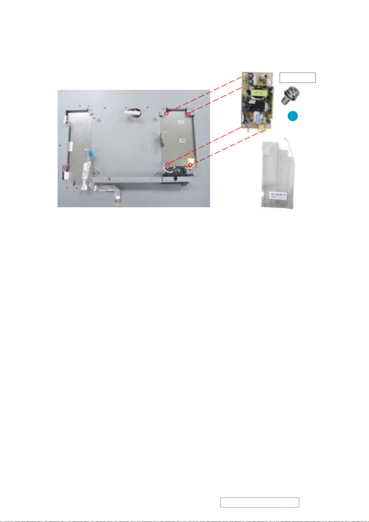
Power Board
85.1F123.060
8
Power Board Mylar
8. Unscrew four screws that secure Power Board and disconnect the wire to remove Power Board.
Detach Power Board Mylar.
X 4
ViewSonic Corporation Confidential
14
-
Do Not Copy VP171s/b-2
Page 19
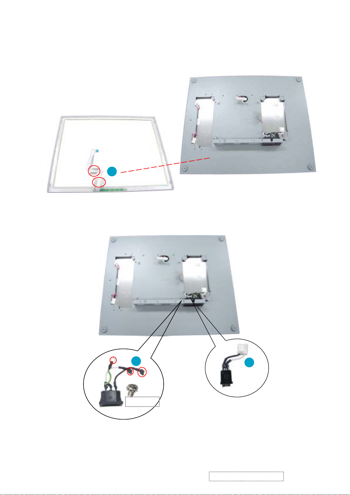
3-4 Disassembly of Front Cover Module, LCD Panel, Switch
and Inlet Wires
Front Cover
Control Board wire
1
1. Remove two tapes of Control Board wire and detach Front Cover from LCD Bracket.
2
Switch
Wire
X 1
85.1C124.060
Inlet Wire
2. Unscrew one screw that secures Inlet Wire and disconnect two wires that are connected to Switch Wire.
3. Use the tool to pull and press out Inlet and Switch Wires.
ViewSonic Corporation Confidential
15
3
-
Do Not Copy VP171s/b-2
Page 20
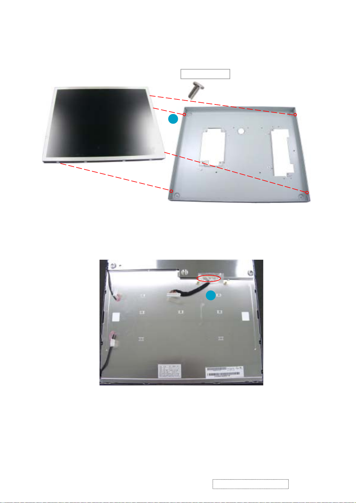
LCD Panel
85.ZA123.040
X 4
4
4. Unscrew four screws beside LCD Bracket to detach LCD Panel from LCD Bracket.
LCD Bracket
5
5. Turn LCD Panel around and remove the tape on the wire to disconnect the wire.
ViewSonic Corporation Confidential
16
-
Do Not Copy VP171s/b-2
Page 21
4. Troubleshooting Procedure
This chapter provides technicians and people who have an electronic background a pri-
mary description about maintaining the product. Moreover, you can get the appropriate opera-
tion to solve some complicated problems of component repairing and professional problems.
4-1 Equipment Needed
- VP171 Monitor
- Philips Screw Driver #101 and #107
- Electronic Hex Nut M5mm
- PC(Personal Computer) with SXGA resolution / Pattern Generator
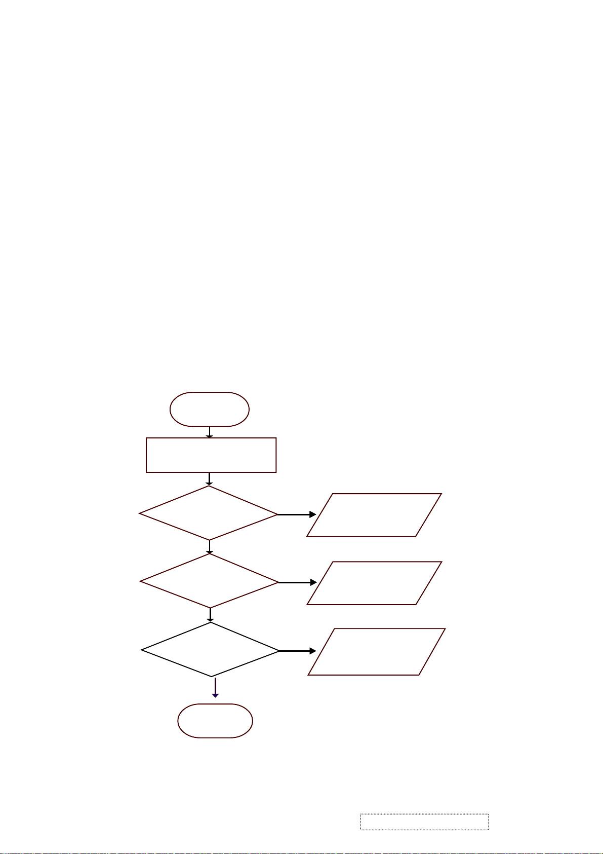
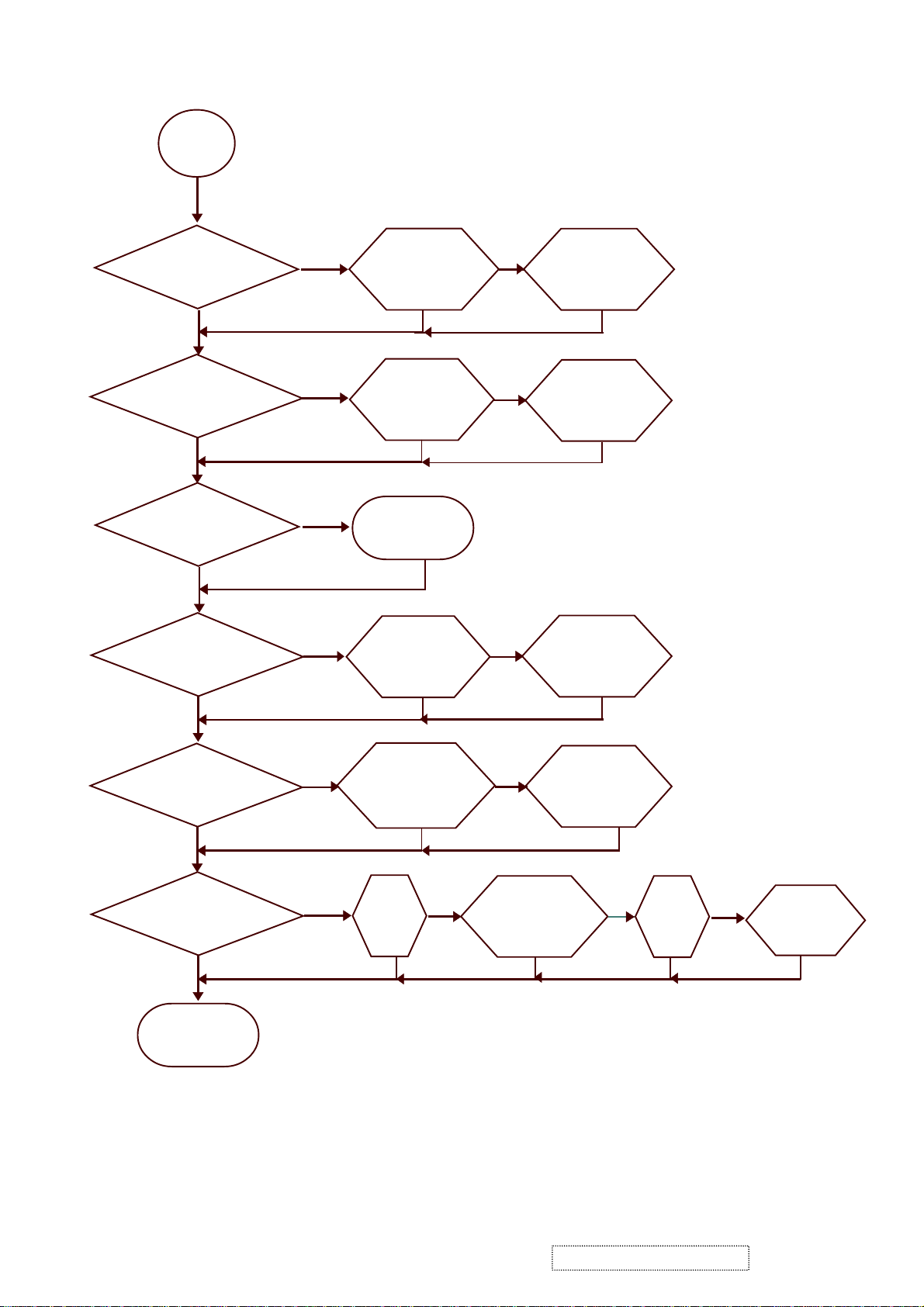
4-2 Main Procedure
Start
Power-on
Power LED ok ?
Ye s
Is display
performance ok ?
Yes
Is function
adjustment ok ?
No
No
No
A. Power Circuit
Troubleshooting
B. Performance
Troubleshooting
C. Control Function
Troubleshooting
Yes
End
ViewSonic Corporation Confidential
17
-
Do Not Copy VP171s/b-2
Page 22
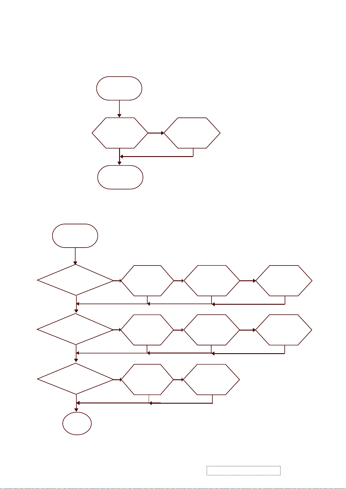
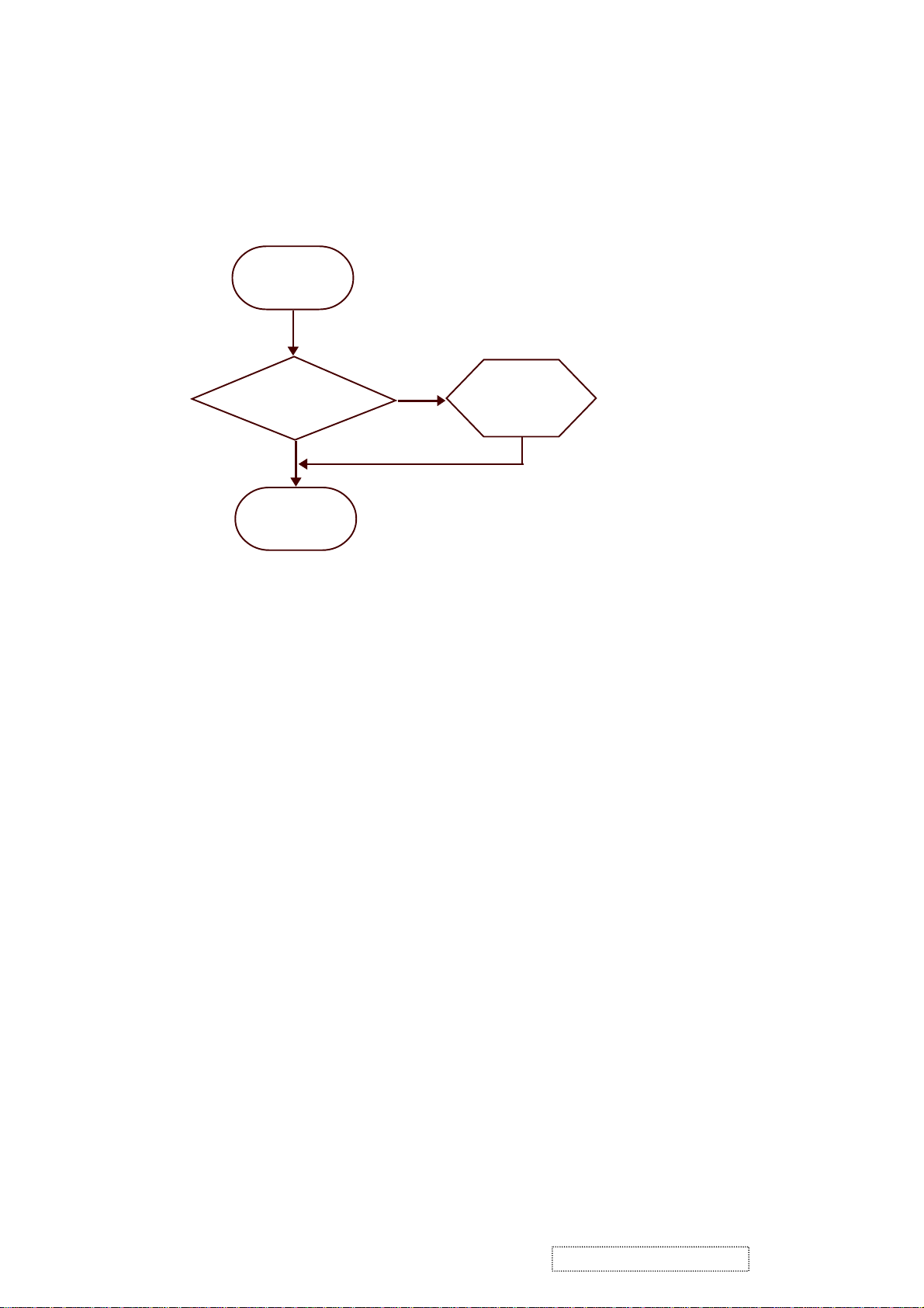
4-2.1 A. Power Circuit Troubleshooting
Start
Change
Power
Board
Yes
End
No
Change
Main Board
Yes
4-2.2 B. Performance Troubleshooting
Start
Is screen black ?
Yes
Change
Inverter Board
No
Change
Main Board
No
Change
LCD Panel
No
Is screen white ?
Ye s
Replug/Change
No
Abnormal Color ?
No
1
ViewSonic Corporation Confidential
Ye s
Yes
FPC Cable
Yes
Change
Main Board
Yes
No
No
Yes
Change
Main Board
Yes
Change
LCD Panel
Yes
18
Ye s
No
-
Do Not Copy VP171s/b-2
Change
LCD Panel
Yes
Page 23
1
Is screen scrolling ?
No
Is screen flickering ?
No
Is LCD line defective ?
No
Bad Uniformity ?
Ye s
Yes
Yes
Ye s
Change
VGA Cable
Yes
Change
Main Board
Yes
Change
LCD Panel
Yes
Change
Inverter Board
No
No
No
Change
Main Board
Yes
Change
LCD Panel
Yes
Change
LCD Panel
No
Yes
Yes
Adjust Fine
Have line bar or noise?
Yes
Tune Sharpness or Auto
No
Change
Main Board
Adjustment
No
Ghost image ?
Yes
Refer to
Notice 1
Yes
No
Adjust Fine
Tune Sharpness or Auto
No
Ye s
Refer to
Notice 2
No
Change
Main Board
Adjustment
No
Yes
Yes
Yes
Yes
End
Notice :
1. Make sure VGA cable connect to PC directly and not through a Data transfer or Distribution......After this
action if Ghost image disappear, go to Yes; else, go to No.
2. Check the compatibility on the computer. If it is compatibility problem, feedback the information to ViewSonic;
else, go to No.
ViewSonic Corporation Confidential
19
-
Do Not Copy VP171s/b-2
Page 24
4-2.3 C. Control Function Troubleshooting
Start
Change
Control Board
Yes
End
No
Change
Main Board
Ye s
ViewSonic Corporation Confidential
20
-
Do Not Copy VP171s/b-2
Page 25
5. Function Test and Alignment Procedure
5-1
5-2
5-3
Product
- 17 LCD Monitor
Test Equipment
- Color Video Signal & Pattern (or PC with SXGA resolution)
Hot Key
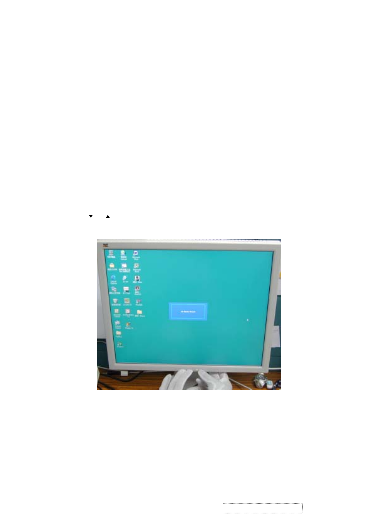
1). All Mode Reset:
Press , buttons simultaneously and Power on with signal, hold on for 3 seconds. Then the
screen will show All Mode Reset.
ViewSonic Corporation Confidential
21
-
Do Not Copy VP171s/b-2
Page 26
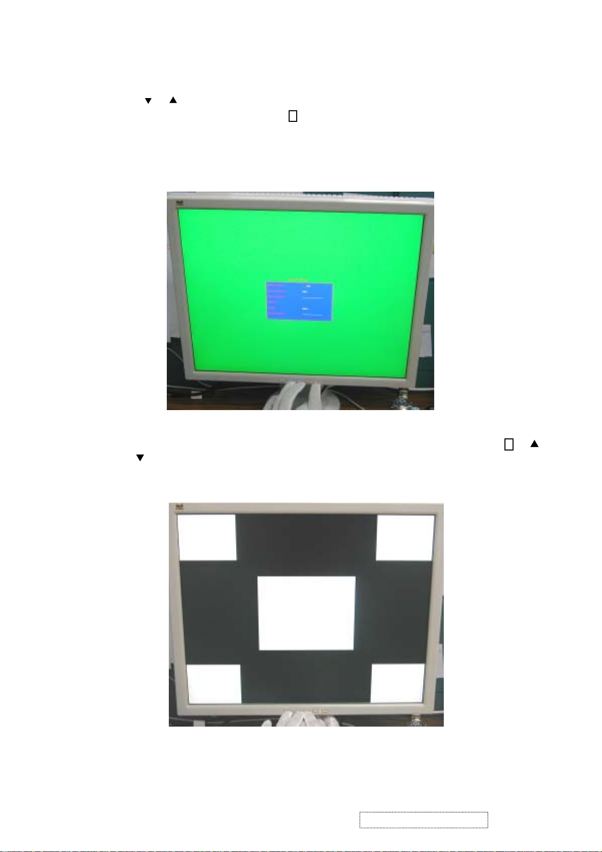
2). Burn In Mode:
Press , buttons simultaneously and Power on without signal, hold on for 3 seconds. Then the
screen will show Burn In Mode. Press button, you can find the information about this monitor.
1
3). White Balance:
Set the screen on 640*480@60Hz resolution pure black and white pattern, no other color. Press ,
and simultaneously.
1
ViewSonic Corporation Confidential
22
-
Do Not Copy VP171s/b-2
Page 27

4). OSD Lock :
Press and buttons simultaneously for 10 seconds, and the OSD will lock. Repeat the action, and the
1
OSD will unlock.
5). Power Lock :
Press and buttons simultaneously for 10 seconds, and the Power will lock. Repeat the action, and
1
the Power will unlock.
ViewSonic Corporation Confidential
23
-
Do Not Copy VP171s/b-2
Page 28

6). Contrast and Brightness Recall :
Press and buttons simultaneously, and the contrast and brightness will restore the factory defaults.
7). Test Mode(720*400)/Graphic Mode (640*400) exchange :
Press and buttons simultaneously.
5-4
Before function test and alignment, each LCD Monitor should be run-in and warmed-up for at least 30 minutes with the
following conditions:
a). In room temperature,
b). With full-white screen, R.G.B. Black
c). With cycled display modes,
640*480 (H=43.27kHz, V=85Hz)
800*600 (H=53.7kHz, V=85Hz)
1024*768 (H=68.67kHz, V=85Hz)
1280*1024 (H=79.97kHz, V=75Hz)
1
2
Test Condition
ViewSonic Corporation Confidential
24
-
Do Not Copy VP171s/b-2
Page 29

5-5
Test Display Modes & Pattern
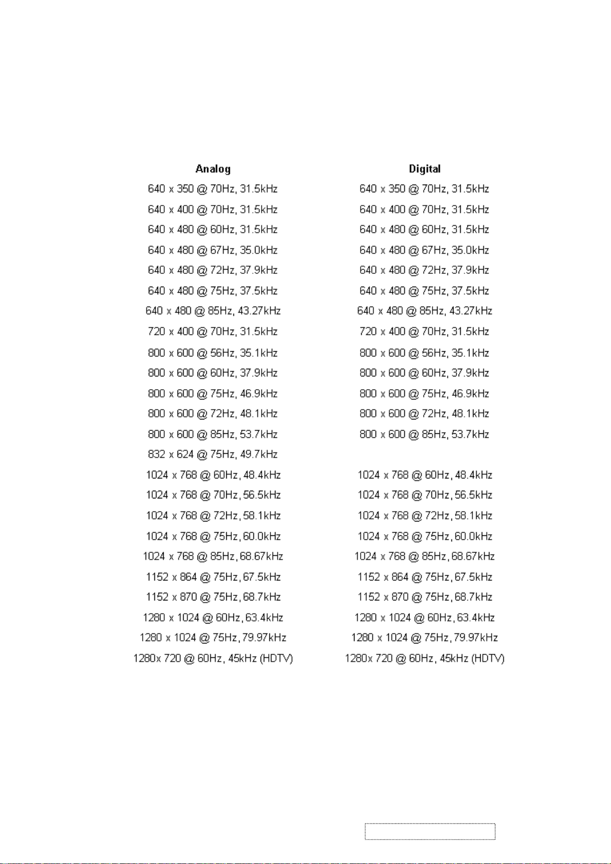
5-5.1 Compatible Modes
VP171 (AU Pa nel: M17EN05 V1):
Analog :
640 x 350 @ 70Hz, 31.5kHz
640 x 480 @ 60Hz, 31.5kHz
640 x 480 @ 67Hz, 35.0kHz
640 x 480 @ 75Hz, 37.5kHz
640 x 480 @ 72Hz, 37.9kHz
640 x 480 @ 85Hz, 43.27kHz
720 x 400 @ 70Hz, 31.5kHz
800 x 600 @ 56Hz, 35.1kHz
800 x 600 @ 60Hz, 37.9kHz
800 x 600 @ 75Hz, 46.9kHz
800 x 600 @ 72Hz, 48.1kHz
800 x 600 @ 85Hz, 53.7kHz
832 x 624 @ 75Hz, 49.7kHz
1024 x 768 @ 60Hz, 48.4kHz
1024 x 768 @ 70Hz, 56.5kHz
1024 x 768 @ 72Hz, 58.1kHz
1024 x 768 @ 75Hz, 60.0kHz
1024 x 768 @ 85Hz, 68.67kHz
1152 x 870 @ 75Hz, 68.6kHz,
1280 x 1024 @ 60Hz, 63.4kHz
1280 x 1024 @ 75Hz, 79.97kHz
1280 x 720 @ 60Hz, 45kHz
Digital :
640 x 350 @ 70Hz, 31.5kHz
640 x 400 @ 70Hz, 31.5kHz
640 x 480 @ 60Hz, 31.5kHz
640 x 480 @ 75Hz, 37.5kHz
640 x 480 @ 72Hz, 37.9kHz
640 x 480 @ 85Hz, 43.27kHz
720 x 400 @ 70Hz, 31.5kHz
800 x 600 @ 56Hz, 35.1kHz
800 x 600 @ 60Hz, 37.9kHz
800 x 600 @ 75Hz, 46.9kHz
800 x 600 @ 72Hz, 48.1kHz
800 x 600 @ 85Hz, 53.7kHz
1024 x 768 @ 60Hz, 48.4kHz
1024 x 768 @ 70Hz, 56.5kHz
1024 x 768 @ 72Hz, 58.1kHz
1024 x 768 @ 75Hz, 60.0kHz
1024 x 768 @ 85Hz, 68.67kHz
1152 x 870 @ 75Hz, 68.6kHz,
1280 x 1024 @ 60Hz, 63.4kHz
1280 x 1024 @ 75HZ,79.97khz
1280 x 720 @ 60Hz, 45kHz
ViewSonic Corporation Confidential
25
-
Do Not Copy VP171s/b-2
Page 30

5 -5.2 Function Test Display Pattern
metI tnetnoCtseT nrettaP noitacificepS krameR
1
2ssenthgirB/tsartnoCelacSyarG61
3yradnuoB
4
5
6eniL/lexiPdaeD
7ecnalaBetihW
&ycneuqerF
gnikcarT
roloC,B,G,R
ecnamrofreP
ytimrofinUneercS
rekcilF&
erioMeniLeniF.esionyvawlausivetanimilE1erugiF
ebdluohsslevelyarg61
.elbahsiugnitsid
&latnoziroH
ssenkcihTlacitreV
roloCB.G.R
seitisnetnI
etihWlluF.cepsehthtiwtnailpmocebdluohS7erugF
neercSetihW
neercSkraD
kcalB&etihW
nrettaP
.emarf
.lamroneb
.cepsehthtiwtnailpmoc
oedivfonoitisop.treVdna.zroH
dluohsroloc,B,G,RhcaefotsartnoC
.rolocrehtoon,nrettapkcalbdna
2erugiF
dluohs
neercsehtnihtiwebotelbatsujdaeb
ebdluohsslexipdaedfosrebmunehT
etihwerupehtevahtsumneercsehT
3erugiF
erugiF
6,5,4
8,7erugiF
9erugiF
Fine Line Morie Pattern (Figure 1) Gray Scale Pattern (Figure 2)
Horizontal & Vertical Thickness Pattern R. Color Pattern (Figure 4)
(Figure 3)
ViewSonic Corporation Confidential
26
-
Do Not Copy VP171s/b-2
Page 31

G. Color Pattern (Figure 5) B. Color Pattern (Figure 6)
Full White Pattern (Figure 7) Dark Screen Pattern (Figure 8)
Black-White Pattern (Figure 9)
ViewSonic Corporation Confidential
27
-
Do Not Copy VP171s/b-2
Page 32

5-6
5-6.1 All Modes Reset
5-6.2 Auto Image Adjust
5-63 Firmware and DDC
5-6.4 Fine Tune and Sharpness
Function Test and Alignment Procedure
You should do All Mode Reset (Refer to Chapter 5-3) first.
This action will allow you to erase all end-users settings and restore the factory defaults.
Please select and enter Auto Image Adjust function on Main Menu to see if it is workable. The Auto Image
Adjust function is aimed to offer a better screen quality by built-in ASIC. For optimum screen quality, the user has
to adjust each function manually.
Test Pattern: Burn In Mode (Refer to Chapter 5-3)
- Make sure the F/W is the latest version.
- Make sure the S/N is the same as the Spec. label.
- Make sure the model name is correct.
Test Signal: 1280*1024 @60Hz
Test Pattern: Line Moire Pattern
- Check and see if the image has noise and focus performs well.
eliminate visual line bar.
- If not, readjust by the following steps :
(a) Select and enter Fine Tune function on Manual Image Adjust to adjust
the image to eliminate visual wavy noise.
(b) Then, select and enter Sharpness function to adjust the clarity and focus
of the screen image.
5-6.5 Boundary
Test Signal : 1280*1024@60Hz
Test Pattern : Horizontal & Vertical Line Thickness Pattern
- Check and see if the image boundary is within the screen frame.
- If not, readjust by the following steps :
(a) Select and enter Manual Image Adjust function on OSD Main Menu.
(b) Then, select and enter Horizontal Size or Horizontal/Vertical Position
function to adjust the video boundary to be full scanned and within screen frame.
ViewSonic Corporation Confidential
28
-
Do Not Copy VP171s/b-2
Page 33

5-6.6 White Balance
Test Signal : 1280*1024 @60Hz
Test Pattern: Full White and Black Pattern
- Refer to Chapter 5-3
5-6.7 R,G,B, Colors Contrast
Test Signal: 1280*1024@60Hz
Test Pattern: R,G,B Color Intensities Pattern and 16 Gray Scale Pattern
- Check and see if each color is normal and distinguishable.
- If not, please return the unit to repair area.
5-6.8 Screen Uniformity and Flicker
Test Signal: 1280*1024@60Hz
Test Pattern: Full White Pattern
- Check and see if it is in normal condition.
5-6.9 Dead Pixel and Line
Test Signal: 1280*1024@60Hz
Test Pattern: Dark and White Screen Pattern
- Check and see if there are dead pixels on LCD panel with shadow gauge and filter film.
- The total numbers and distance of dead pixels should be compliant with the spec.
5-6.10 Check for Secondary Display Modes
Test Signal:
Analog : 640*350@70Hz; 640*480@60/67/72/75/85Hz;
720*400@70Hz; 800*600@56/60/72/75/85Hz;
832*624@75Hz, 1024*768@60/70/72/75/85Hz;
1152*870@75Hz, 1280*720@60Hz, 1280*1024@60/75Hz
Digital : 640*350@70Hz; 640*450@75Hz; 640*480@60/72/75Hz;
720*400@70Hz; 800*600@56/60/72/75/85Hz;
1024*768@60/70/72/75/85Hz; 1152*870@75Hz, 1280*720@60Hz, 1280*1024@60/75Hz
- Normally when the primary mode 1280*1024@75Hz is well adjusted and
compliant with the specification, the secondary display modes will also be
compliant with the spec. It is still necessary to check with the
to make sure every secondary is compliant with the
specification.
general test pattern
5-6.11 All Modes Reset
After final QC step, we have to erase all saved changes again and restore the factory
defaults. You should do All Mode Reset again.
5-6.12 Power Off Monitor
Turn off monitor by pressing Power button, and turn off the Switch that is back of the monitor.
ViewSonic Corporation Confidential
29
-
Do Not Copy VP171s/b-2
Page 34

6. Firmware Upgrade Procedure
Equipment Needed6-1
- VP171/s/b Series Monitor
- Fixture for Firmware Upgrade
- Power Adapter (P/N : 47.58201.001) *1 for Fixture
- VGA Cable (P/N : 42.59901.008) *1
- PC (Personal Computer)
- LTP Cable (P/N : 42.59906.001) *1
- Firmware Upgrade Program
- One additional monitor for checking the program execution
Printer Port
VP171 Monitor
Fixture
VGA Cable (P/N: 42.59901.008)
PC
ViewSonic Corporation Confidential
30
-
Do Not Copy VP171s/b-2
Page 35

Power Adapter for Fixture
(P/N: 47.58201.001)
LTP Cable (P/N: 42.59906.001)
6-2
JP1 : to Power
Adapter
Set-up Procedure
1. Connect P2 of Fixture with printer port of PC by LTP Cable.
2. Connect P1 of Fixture with VP171/s/b Monitor by VGA Cable.
3. Plug Power Adapter to Fixture.
4. Connect Power Cord to VP171/s/b Monitor, and turn on the Power Switch.
5. Connect PC to the additional monitor.
Turn on the Power Switch
P1 : to VGA Cable
VGA Port
P2 : to LTP Cable
ViewSonic Corporation Confidential
31
VP171
VLCDS25972-1W
A1T020100001
Connect to Power Cord
-
Do Not Copy VP171s/b-2
Page 36

6. Install GProbe Program by selecting and clicking Gprobe icon.
Press Yes or Next buttons until the program is finished.
ViewSonic Corporation Confidential
32
-
Do Not Copy VP171s/b-2
Page 37

ViewSonic Corporation Confidential
33
-
Do Not Copy VP171s/b-2
Page 38

ViewSonic Corporation Confidential
34
-
Do Not Copy VP171s/b-2
Page 39

Firmware Upgrade Procedure6-3
1. Save these three files <bdisp.txt>, <p204_205.bin> and <vp171_v4_24.bin> in the computer.
2. Open <bdisp.txt> file.
Key in the path where you save the driver <p204_205.bin> and firmware
<vp171_v4_24.bin>.
ViewSonic Corporation Confidential
35
-
Do Not Copy VP171s/b-2
Page 40

3. Execute Gprobe program.
4. Key in batch c:\VP171\bdisp.txt after GProbe :>, then press Enter key to
begin programming automatically.
the path is where you save <bdisp.txt> file
ViewSonic Corporation Confidential
36
-
Do Not Copy VP171s/b-2
Page 41

5. The successful picture is as follows :
6.Enter Burn In Mode (Refer to Chapter 5-3), and you could find that Serial
Number disappears.
ViewSonic Corporation Confidential
37
-
Do Not Copy VP171s/b-2
Page 42

7.Turn off the power switch of the rear cover of VP171/s/b, and turn it on again.
Then enter Burn In Mode, and Serial Number will appear. Check if the version of BIOS is correct.
Power Switch
VP171
VLCDS25972-1W
A1T020100001
8.Connect the signal, and the monitor will slant to red color. Refer to Chapter 5-3
to do White Balance.
9. At last, do All Mode Reset.
ViewSonic Corporation Confidential
38
-
Do Not Copy VP171s/b-2
Page 43

7. DDC Key In Procedure
7-1
Equipment Needed
- VP171/s/b Series Monitor
- Fixture(V3) for DDC Key In (JP3 must be closed)
- RS232 Cable (P/N : 42.55907.001) *1
- VGA Cable (P/N : 42.59901.008) *2
- DVI-DVI Cable *1
- PC (Personal Computer)
- Power Adapter (P/N: 47.56001.501) *1 for Fixture
- DDC Key In Program
- One additional monitor for checking the program execution
VP171 Monitor
COM1 : to
RS232 Cable
PC
Fixture
VGA Cable (P/N: 42.59901.008)
RS-232 Cable (P/N: 42.55907.001)
ViewSonic Corporation Confidential
39
-
Do Not Copy VP171s/b-2
Page 44

DV I - DV I C a b l e
Power Adapter for Fixture
(P/N: 47.56001.501)
7-2
Set-Up Procedure
1. Connect P2 and P4 of Fixture with VGA ports of VP171/s/b by two VGA Cables.
2. Connect P3 of Fixture with DVI port of VP171/s/b by DVI-D Cable.
3. Connect P1 of Fixture with COM1 of PC by RS232 Cable.
4. Plug Power Adapter to Fixture.
5. Connect Power Cord to VP171/s/b Monitor, and turn on the Power Switch.
6. Connect PC to the additional monitor.
P3 : to DVI-DVI
Cable
P2 & P4 : to VGA Cables
Turn on the Power Switch
JP1 : to
Power
Adapter
P1 : to
RS232 Cable
VGA Port
DVI Port
ViewSonic Corporation Confidential
40
VP171
VLCDS25972-1W
A1T020100001
Connect to
Power Cord
-
Do Not Copy VP171s/b-2
Page 45

7-3
DDC Key In Procedure
1. Select and execute DDC Key In program.
2. Key in the serial number and press Enter key.
ViewSonic Corporation Confidential
41
-
Do Not Copy VP171s/b-2
Page 46

3. The successful picture is as follows :
(There are checksum values appearing when VGA and DVI success.)
4. Press ~ button (Shift+ ) to check DDC CheckSum is correct or not.
`
ViewSonic Corporation Confidential
42
-
Do Not Copy VP171s/b-2
Page 47

5. Enter Burn In Mode (refer to Chapter 5-3). Turn off the power switch of the
rear cover of VP171/s/b, and turn it on again. Then enter Burn In Mode again
and Information of OSD Main Menu. Check if the information is correct.
ViewSonic Corporation Confidential
43
-
Do Not Copy VP171s/b-2
Page 48

8. Panel Specification
8-1 LCD Panel (AU Optronics:M170EG01 V2)
A. General Description
This specification applies to the 17.0 inch Color TFT/LCD Module M170EG01 V2.
This module is designed for a display unit of personal computer.
The display supports the SXGA (1280(H) x 1024(V)) screen format and 16.2M colors (RGB 6-bits + FRC
data).
All input signals are 2 Channel LVDS interface compatible.
This module does not contain an inverter card for backlight.
B. Display Characteristics
The following items are characteristics summary on the table under 25 ¢J condition:
ViewSonic Corporation Confidential
44
-
Do Not Copy VP171s/b-2
Page 49

C. Function Block Diagram
The following diagram showa the functional block of the 17.0 inches Color TFT-LCD module.
ViewSonic Corporation Confidential
45
-
Do Not Copy VP171s/b-2
Page 50

D. Optical Characteristics
The Optical Characteristics are measured under stable conditions at 25oC.(Room T e mperature)
Note 1: Definition of Response time:
The output signals of photo detector are measured when the input signals are changed from “Black”
to “White”(rising time), and from “White” to “Black” (falling time), respectively.
The response time is interval between the 10% and 90% of amplitudes
ViewSonic Corporation Confidential
46
-
Do Not Copy VP171s/b-2
Page 51

Note 2: Brightness uniformity of these 9 points is defined as below:
Note 3: Crosstalk is defined as below:
ViewSonic Corporation Confidential
47
-
Do Not Copy VP171s/b-2
Page 52

Note 4:
Test Pattern: Subchecker Pattern
Method : Record dBV & DC value with (WESTAR)TRD-100
E . Pixel format image
Following figure shows the relationship of the input signals and LCD pixel format.
ViewSonic Corporation Confidential
48
-
Do Not Copy VP171s/b-2
Page 53

F. Electrical Characteristics
F-1: Absolute Maximum Rating
Absolute Maximum rating of the module is as following:
- TFT LCD Module
- Backlight Unit
- Backlight Unit
Note 1: With in T a (25
· ·
)
Note 2: Perma nent damage to the device may occur if exceed maximum values.
Note 3: For quality performance, please regfer to AUO IIS (Incoming Inspection Standard).
ViewSonic Corporation Confidential
49
-
Do Not Copy VP171s/b-2
Page 54

9. Packing For Shiping
9-1
Packing Procedure
1. Put the PE bag on the monitor.
2. Put the Cushions on the monitor.
ViewSonic Corporation Confidential
50
-
Do Not Copy VP171s/b-2
Page 55

3. Put the monitor into carton.
Note : LCD Panel should face to the side as the following picture.
4. Put the accessories into the carton as the following picture. Then close the cover of the carton and
tape.
DV I - D
ViewSonic Corporation Confidential
51
-
Do Not Copy VP171s/b-2
Page 56

10. Appendix
10-1
The Serial Number System Definition
10-1.1
A. Model Number :
VLCDS25972-1W for VP171
VLCDS25972-2W for VP171b
VLCDS25972-3W for VP171s
B . Serial Number Format
Serial Number for LCD Display
PPP YY WW XXXXX
1 2 3 4
: PPP = Regional Product ID Code [ ex : A1T = VP171; A2Q= VP171s (EG01 V0); A1U=VP171b (EG01 V0)
1
2
: YY = La st 2 digits of manufacturing year (ex : 02 = 2002)
3
: WW = Manufacturing week of year
4
: XXXXX = Sequence number
EX: A1T020100001
This label “A1T020100001” represents VP171 monitor. The sequence number is 00001,
made on 1-week of 2002.
PJK = VP171b (EG01 V2); PJJ = VP171s (EG01 V2) ]
ViewSonic Corporation Confidential
52
-
Do Not Copy VP171s/b-2
Page 57

10-1.2
Serial Number for PCBA Main Board
M VV B Y X A1 EEEE
1 2 3 4 5 6 7
1
2
3
4
5
6
7
EX: MK2M32B10043
This label “MK2M32B10043” represents Main Board Vender is Might, version is B1 for VP171 on Feb.,
2003. Its serial
: M = V ender (ex : M=Might)
: VV = Model Code [ex : K2=VP171/s/b series; R2=VP171 (AU EG01 V1 Pa nel)
R9=VP171 (AU EG01 V0 Pa nel
S3=VP171 (AU EG01 V2 Pa nel]
: B = PCBA Board (ex : M=Main Board)
: Y = La st Digit of the Year (ex : 2 = 2002 )
: X = Month (ex : Ja n.~ Sep.=1~9, Oct.~Dec.=X, Y, Z)
: A1 = Version (ex : A1, B2.....)
: EEEE = Sequence number (from 0001~)
code is 0043.
ViewSonic Corporation Confidential
53
-
Do Not Copy VP171s/b-2
Page 58

Function of Boards10-2
A. Main Board
CN1
JP1
JP10
10-2-1 CN1 Connector
JP8
JP6 JP5 JP4
#niP noitpircseD noitcnuF
1AV21+V21+
2AV21+V21+
3DNGdnuorG
4DNGdnuorG
10-2-2
JP1 Connector
#niP noitpircseD noitcnuF
1
2
3
4
5DNGdnuorG
6AV21+V21+
7DNGdnuorG
AV21+V21+
DNGdnuorG
IRBlortnoCssenthgirB
DNGdnuorG
8nOlortnoCFFO/NOthgilkcaB
9DNGdnuorG
01DNGdnuorG
ViewSonic Corporation Confidential
54
-
Do Not Copy VP171s/b-2
Page 59

JP4 Connector10-2-3
#niP noitpircseD noitcnuF
1
2
3
4
5+4XRnoitcennoCoN
6LCSkcolCB2CDD
7ADSataDB2CDD
8.C.NnoitcennoCoN
9-1XR
01+1XR
11DNGdnuorG
21.C.NnoitcennoCoN
31.C.NnoitcennoCoN
-2XR
+2XR
DNGdnuorG
-4XRnoitcennoCoN
tupnilaitnereffidevitagenSDMT
2lennahc
tupnilaitnereffidevitisopSDMT
2lennahc
tupnilaitnereffidevitagenSDMT
1lennahc
tupnilaitnereffidevitisopSDMT
1lennahc
41V5IVDV5+
51DNGdnuorG
61SENShgiHlluP
71-0XR
81+0XR
91DNGdnuorG
02.C.NnoitcennoCoN
12.C.NnoitcennoCoN
22DNGdnuorG
32+CXR
42-CXR
52.C.NnoitcennoCoN
62.C.NnoitcennoCoN
tupnilaitnereffidevitagenSDMT
0lennahc
tupnilaitnereffidevitisopSDMT
0lennahc
,tupnilaitnereffidevitisopSDMT
kcolcecnerefer
,tupnilaitnereffidevitagenSDMT
kcolcecnerefer
72.C.NnoitcennoCoN
82.C.NnoitcennoCoN
92DNGdnuorG
ViewSonic Corporation Confidential
55
-
Do Not Copy VP171s/b-2
Page 60

10-2-4
JP5/6
#niP noitpircseD noitcnuF
1
2
3
4
5DNGdnuorG
6DNGdnuorG
7DNGdnuorG
8DNGdnuorG
9V5V5+
01DNGdnuorG
11.C.NnoitcennoCoN
21ADSataDlaireS
31SHcnySlatnoziroH
41SVcnySlacitreV
51LCSkcolClaireS
NIRtupnIoediVdeR
NIGtupnIoediVneerG
NIBtupnIoediVeulB
.C.NnoitcennoCoN
10-2-5
JP8
#niP noitpircseD noitcnuF
1
2
3
4
5SDVLLESredrOataDSDVLtceleS
6tnocVnoitcennoCoN
7DNGdnuorG
8+3NIOxR
9-3NIOxR
01+NIKLCOxR)ataDnevE(kcolCgnilpmaSevitisoP
11-NIKLCOxR)ataDnevE(kcolCgnilpmaSevitageN
LPVV5+
LPVV5+
LPVV5+
DNGdnuorG
3lexiPfOataDnoissimsnarTevitisoP
)ataDnevE(
3lexiPfOataDnoissimsnarTevitageN
)ataDnevE(
ViewSonic Corporation Confidential
56
-
Do Not Copy VP171s/b-2
Page 61

#niP noitpircseD noitcnuF
21+2NIOxR
31-2NIOxR
41DNGdnuorG
51+1NOxR
61-1NOxR
1
lexiP
71DNGdnuorG
81+0NIOxR
91-0NIOxR
02+3NIExR
12-3NIExR
2lexiPfOataDnoissimsnarTevitisoP
)ataDnevE(
2lexiPfOataDnoissimsnarTevitageN
)ataDnevE(
1lexiPfOataDnoissimsnarTevitisoP
)ataDnevE(
fOataDnoissimsnarTevitageN
)ataDnevE(
0lexiPfOataDnoissimsnarTevitisoP
)ataDnevE(
0lexiPfOataDnoissimsnarTevitageN
)ataDnevE(
3lexiPfOataDnoissimsnarTevitisoP
)ataDddO(
3lexiPfOataDnoissimsnarTevitageN
)ataDddO(
22+NIKLCExR)ataDnevE(kcolCgnilpmaSevitisoP
32-NIKLCExR)ataDddO(kcolCgnilpmaSevitageN
42DNGdnuorG
52+2NIExR
62-2NIExR
72+1NIExR
82-1NIExR
92+0NIExR
03-0NIExR
2lexiPfOataDnoissimsnarTevitisoP
)ataDddO(
2lexiPfOataDnoissimsnarTevitageN
)ataDddO(
1lexiPfOataDnoissimsnarTevitisoP
)ataDddO(
1lexiPfOataDnoissimsnarTevitageN
)ataDddO(
0lexiPfOataDnoissimsnarTevitisoP
)ataDddO(
0lexiPfOataDnoissimsnarTevitageN
)ataDddO(
ViewSonic Corporation Confidential
57
-
Do Not Copy VP171s/b-2
Page 62

10-2-6
JP10
#niP noitpircseD noitcnuF
1
2
3
4
5GDELKneerGDELrewoP
6.C.NnoitcennoCoN
7PUKesaercnI
8NWODKesaerceD
9.C.NnoitcennoCoN
01TCELESKyeKtceleS
11UNEMKyeKuneM
21.C.NnoitcennoCoN
DNGdnuorG
RWPKhctiwSrewoP
DNGdnuorG
RDELKdeRDELrewoP
ViewSonic Corporation Confidential
58
-
Do Not Copy VP171s/b-2
Page 63

B. Inverter Board
10-2-7
10-2-8
#niP noitpircseD noitcnuF
1niVV21+
2niVV21+
The Location of Connectors
CN3
CN1
CN1 Connector
CN2
3ffO/nOffO/nO
4ssenthgirBlortnoCssenthgirB
5DNGdnuorG
6DNGdnuorG
10-2-9
#niP noitpircseD noitcnuF
1.V.HtuptuOegatloVhgiH
2DNGdnuorG
10-2-10
#niP noitpircseD noitcnuF
1.V.HtuptuOegatloVhgiH
CN2 Connector
CN3 Connector
2DNGdnuorG
ViewSonic Corporation Confidential
59
-
Do Not Copy VP171s/b-2
Page 64

C. Power Board
10-2-11
The Location of Connectors
CN2
CN1
11-2.13 CN1
#niP noitpircseD noitcnuF
1
2
3
11-2.14 CN2
LeniL
GdnuorG
NlartueN
#niP noitpircseD noitcnuF
1
2
V21+V21+
DNGdnuorG
ViewSonic Corporation Confidential
60
-
Do Not Copy VP171s/b-2
Page 65

11. PCB Layout
ViewSonic Corporation Confidential
61
-
Do Not Copy VP171s/b-2
Page 66

ViewSonic Corporation Confidential
62
-
Do Not Copy VP171s/b-2
Page 67

12. Schematic Diagram
+12VA
CN1
1
2
3
4
TU2001WNR-5P
+12VA
BNC-2
JP2
+12VA
GND
3
C5
0.1uF
1
2
+12VA
C6
470uF/16V
C7
0.1uF
+12VA
C8
0.1uF
L1 22uH
C10
2200uF/16V
BRIGHT3
Debug
NC
C29
0.1uF
+5VIN
C30
1000uF/10V
L4 22uH L5 22uH
LESR
C27
100uF/16V
C28
0.1uF
U4 AP1501
1 2
+VIN VOUT
S.S
5
C33
0
VOS
GND
5V_MAIN=2.5A
3
4
L3 150uH
D1
IN5822
+12VIN
C13
NC
U1
AIC1084
C17
0.1u
C23
0.1uF
C2
0.1uF
3 1
VIN VOUT
GND
2
U2
XC6201
3 1
VI VO
GND
2
U3
AIC1084
3 1
VIN VOUT
3.3V_MAIN MAX 5A
GND
2
330/1%
330/1%
C18
0.1u
R1
R4
C19
100uF/16V
R7
200/1%
R8
330/1%
C3
0.1uF
C24
0.1uF
+5V
JP1
1
2
BRI
ON
C21
10k
C14
NC
C31
0.1uF
R3
4.7K
0805
BLON3
100uF/16V
R2
NC
R5
1K
C15
+5V
C11
0.1uF
C12
0.1uF
R6 0
C20
NC
3
4
5
6
7
8
9
10
HEADER 10-2.0
+5V
+5V
C1
100uF/16V
C16
100uF/16V
C22
100uF/16V
+2.5VD
C4
100uF/16V
+3.3VA
+3.3VD
C25
100uF/16V
+3.3VD
+5V
+12V
L8 22uH
2 3
100uF/16V
R12
10K
C38
C52
NC
R13
33
C39
0.1uF
C49
NC
C53
NC
C176
0.1uF
1
Q2
2N3904
D
R9
100K
132
C51
0.1uF
2 3
Q1
AO3400
N
23
SOT
MOSN
G
S
Power NMOS
NMos
VPL
C44
R10
100K
C
3
R11
750R
1000uF/10V
08050805
C45
0.1uF
C46
0.1uF
Title
C36
0.1uF
+5V
C50
PNL_EN3
NC
C54
NC
1
Q3
2N3904
+3.3VA
+2.5VD
Close to GM5120
L6 BEAD 0805
C34
0.1uF
L9 BEAD /0805
C40
0.1uF
L10 BEAD /1206
C42
0.1uF
L11 BEAD /0805
C47
0.1uF
3.3V_DVDD
C35
0.1uF
3.3V_AVDD
C41
0.1uF
2.5V_VDD
C43
0.1uF
2.5V_AVDD
C48
0.1uF
(GM5120)
(GM5120)
(GM5120)
POWER
2
R14
NC
1
B
E
Size Document Number
Date:
Thursday, August 12, 2004
VP171 for AUO EG01
Sheet
1
of
Rev
C
7
ViewSonic Corporation Confidential
63
-
Do Not Copy VP171s/b-2
Page 68

DVI CONNECTOR
JP4
DVI-I
1
RX2-
2
RX2+
3
GND
4
RX4-
5
RX4+
6
SCL
7
SDA
8
VS
9
RX1-
10
RX1+
11
GND
12
RX3-
13
RX3+
GND
RX0-
RX0+
GND
RX5-
RX5+
GND
RXC+
RXC-
RIN
GIN
BIN
GND
5V
HP
HS
DVI_5V
14
15
16
17
18
19
20
21
22
23
24
25
26
27
28
29
R17 NC
R18 NC
DVI_5V
HOT_PLUG
SDA IND
SCL IND
R22 10K
C73
NC
RX2- 3
RX2+ 3
ISP_SDA 3
ISP_SCL 3
RX1- 3
RX1+ 3
RX0- 3
RX0+ 3
RXC+ 3
RXC- 3
C74
NC
R19 100
R20 100
3.3V_DVDD
R15
2.2K
R16
2.2K
VCCNC
SCL
SDA
C55
0.1u
81
7
6
5
D2
SOT23
3
C69
0.1u
DVI_5V +5V
U7
2
NCNCWP
3
4
GND
24LC21A
BAV70
DVI_5V
12
C56
0.1u
R21 NC
R23 NC
DVI_5V 3
DDCSCL2 3
DDCSDA2 3
C63
10uF/25V
+5V
C58
0.1uF
C67
0.1uF
+5V
C59
10uF/25V
For AD8183 VCC
C64
0.01uF
C70
0.1uF
For AD8183 DVCC
C65
0.01uF
1
2
3
4
C68
0.01uF
U6
BOOST
CAP+
GND
CAP-
ICL7660S
OSC
Vout
V+
LV
8
7
6
5
C60
100uF/16V
+5V
C57
0.1uF
0.01uF
-5VA
-5VA
C71
For AD8183 VEE
C62
0.1uF
C72
0.01uF
RIN
GIN
GND
GND
GND
GND
GND
SDA
SCL
BIN
R24
10K
D_SUBJP5
RIN2
GIN2
BIN2
RIN1
GIN1
BIN1
ISP_SDA 3
R29 0
R30
NC
SDA_IN1
HS_DSUB1
VS_DSUB1
SCL_IN1
R53 0
R54
NC
SDA_IN2
HS_DSUB2
VS_DSUB2
SCL_IN2
SDA_IN1 6
HS_DSUB1
VS_DSUB1 6
SCL_IN1 6
SDA_IN2
HS_DSUB2 6
VS_DSUB2
SCL_IN2 6
6
6
6
3.3V_DVDD
R51
10K
DSUB1 3
ISP_SCL 3
DSUB2 3
BIN2
GIN2
RIN2
RIN1
GIN1
BIN1
AGND
R44
75
R45
75
R46
75
R47
75
R48
75
+5V
R49
75
1
RIN
2
GIN
3
BIN
4
NC
5
GND
6
GND
7
GND
8
GND
9
5V
10
GND
11
NC
12
SDA
13
HS
14
VS
15
SCL
D_SUBJP6
1
2
3
R50
4
NC
5
DSUB2_5V
6
7
8
9
5V
10
R55
11
NC
12
13
HS
14
VS
15
R27
DSUB1_5V
R31
0
NC
NC
0
R25
R26 NC
R28
MUX_SEL
3,6
U8
1
IN0A
2
DGND
3
IN1A
4
GND
5
IN2A
6
VCC
7
VEE
8
IN2B
9
GND
10
IN1B
11
GND
12 13
IN0B VCC
NC/AD8183
MUX_B
NC
MUX_G
NC
MUX_R
MUX_SEL
VCC
OE
SELA/B
VCC
OUT0
VEE
OUT1
VCC
OUT2
VEE
DVCC
Switch_enable 3
R138
NC
24
23
22
21
20
19
18
17
16
15
14
-5VA
R34 75
R35 75
R37 75
R39
3.3K
R40
3.3K
R41
3.3K
MUX_B
MUX_G
MUX_R
R32
R33 100 C76 0.01uF
R36 0
R38 100
R42 0
R43 100
AGND
0
C75 0.01uF
C77 0.01uF
C78 0.01uF
C79 0.01uF
C80 0.01uF
RED+ 3
RED- 3
GREEN+ 3
GREEN- 3
BLUE+ 3
BLUE- 3
R52
NC
R136 0
R137 0
ViewSonic Corporation Confidential
64
-
Do Not Copy VP171s/b-2
Title
Size Document Number
Date:
Thursday, August 12, 2004
2-Input Connector
VP171 for AUO EG01
Sheet
2
Rev
of
C
7
Page 69

C81
C82
100uF/16V
3.3V_AVDD
100uF/16V
100uF/16V
2.5V_AVDD 2.5V_AVDD
100uF/16V
C125
0.1uF
3.3V_DVDD
C130
0.1UF
C134
10uF/16V
2
3
4
C96
C109
C119
U10
24LC16B
VCCA0
A1A2WP
SCL
GND
SDA
R80
10K
0.1uF
C97
0.1uF
C110
0.1uF
C120
0.1uF
3.3V_DVDD
C133
NC
3.3V_DVDD
81
7
6
5
R78
D3
1N4148
1 2
C83
0.1uF
C98
0.1uF
C111
0.1uF
C121
100pF
R84
10K
R64 33
R65 33
R132
NC
R74 10K
R75 10K
R76 NC
NC
Q5
SST3906
C84
0.1uF
C99
0.1uF
C112
0.1uF
C85
0.1uF
C100
0.1uF
C113
0.1uF
3.3V_DVDD
R135
4.7K
RMADDR14
RMADDR9
RMADDR8
TP4
R83
5.6K
R61
10K
C131
0.1UF
C86
0.1uF
C101
0.1uF
C114
0.1uF
R62
10K
1
Q4
2N3904
SCL
SDA
R134 0
3.3V_DVDD
R79
10K
2 3
C87
0.1uF
C102
0.1uF
C115
0.1uF
DVI_5V2
C132
0.1UF
SCL
SDA
C88
0.1uF
C103
0.1uF
C116
0.1uF
RESETn
3.3V_DVDD2.5V_VDD
3.3V_DVDD3.3V_DVDD
3.3V_AVDD
C93
C90
0.1uF
C91
0.1uF
C105
0.1uF
C118
0.1uF
C122
0.1uF
3.3V_DVDD
R71
10K
C89
0.1uF
C104
0.1uF
2.5V_VDD2.5V_VDD
C117
0.1uF
R59 100 /NC
WP
C126
0.1uF
C92
0.1uF
0.1uF
3.3V_AVDD
C106
0.1uF
3.3V_AVDD 3.3V_AVDD
C123
5pF
Bank0
R77
10K
C107
0.1uF
14.318MHz
3.3V_DVDD
RMADDR15
RMADDR14
RMADDR13
RMADDR12
RMADDR11
RMADDR10
RMADDR9
RMADDR8
RMADDR7
RMADDR6
RMADDR5
RMADDR4
RMADDR3
RMADDR2
RMADDR1
RMADDR0
FLASH_OEn
C108
100pF
X1
R72 10K
100pF on pin-196
C124
5pF
R60
2.2K
R63
NC
/WR
RMADDR[0..15]
U11
31
WE
30
NC/A17
2
A16
3
A15
29
A14
28
A13
4
A12
25
A11
23
A10
26
A9
27
A8
5
A7
6
A6
7
A5
8
A4
9
A3
10
A2
11
A1
12
A0
24
OE
22
CE
AT49HF/F010-45JC
DQ7
DQ6
DQ5
DQ4
DQ3
DQ2
DQ1
DQ0
VCC
GND
2.5V_AVDD
PNL_EN1
BLON1
DSUB22
ROTATE6
ISP_SDA2
ISP_SCL2
DDCSCL22,6
DDCSDA22,6
RED+2
RED-2
GREEN+2
GREEN-2
BLUE+2
BLUE-2
HS6
VS6
RXC+2
RXC-2
RX2+2
RX2-2
RX1+2
RX1-2
RX0+2
RX0-2
3.3V_DVDD
C129
0.1uF
R57 NC
3.3V_AVDD
RMDATA[0..7]
TCLK
XTAL
Bank0
RESETn
R69 1K
RMADDR15
RMADDR14
RMADDR13
RMADDR12
RMADDR11
RMADDR10
RMADDR9
RMADDR8
RMADDR7
RMADDR6
RMADDR5
RMADDR4
RMADDR3
RMADDR2
RMADDR1
RMADDR0
RMDATA7
RMDATA6
RMDATA5
RMDATA4
RMDATA3
RMDATA2
RMDATA1
RMDATA0
ROM_OEn
LVDSON5
RMDATA7
21
RMDATA6
20
RMDATA5
19
RMDATA4
18
RMDATA3
17
RMDATA2
15
RMDATA1
14
RMDATA0
13
3.3V_DVDD3.3V_DVDD
1
NC
32
16
141
146
150
173
181
187
193
196
164
168
172
160
199
175
178
184
190
197
198
157
158
161
165
169
149
145
140
113
114
152
151
206
207
208
205
204
171
170
167
166
163
162
137
136
159
194
195
179
180
185
186
191
192
174
1%
gm5120
PQFP208
U9
AVDD_DDDS
AVDD_SDDS
AVDD_RPLL
AVDD_IMB
AVDD_RX2
AVDD_RX1
AVDD_RX0
AVDD_RXC
AVDD_BLUE
AVDD_GREEN
AVDD_RED
AVDD_ADC
VDD_RXPLL_2.5
AGND_IMB
AGND_RX2
AGND_RX1
AGND_RX0
AGND_RXC
AGND_RXPLL
SGND_ADC
AGND_ADC
AGND_BLUE
AGND_GREEN
AGND_RED
AVSS_RPLL
AVSS_SDDS
AVSS_DDDS
PPWR
PBIAS
TCLK
XTAL
GPIO20
GPIO19
GPIO18
1
GPIO17
GPIO16/HFSn
GPIO22/HCLK
6
DDC_SCL
7
DDC_SDA
5
RESETn
50
GPIO11/ROM_WEn
RED+
REDGREEN+
GREENBLUE+
BLUEHSYNC
VSYNC
ADC_TEST
RXC+
RXCRX2+
RX2RX1+
RX1RX0+
RX0-
REXT
8
ROM_ADDR15
9
ROM_ADDR14
10
ROM_ADDR13
11
ROM_ADDR12
12
ROM_ADDR11
13
ROM_ADDR10
14
ROM_ADDR9
15
ROM_ADDR8
16
ROM_ADDR7
17
ROM_ADDR6
18
ROM_ADDR5
19
ROM_ADDR4
22
ROM_ADDR3
23
ROM_ADDR2
24
ROM_ADDR1
25
ROM_ADDR0
28
ROM_DATA7
29
ROM_DATA6
30
ROM_DATA5
31
ROM_DATA4
32
ROM_DATA3
33
ROM_DATA2
34
ROM_DATA1
35
ROM_DATA0
36
ROM_OEn
155
153
176
182
VDD_RX2_2.5
VDD_RX1_2.5
VDD1_ADC_2.5
VDD2_ADC_2.5
3.3V_A
AGND
RVSS
RVSS
RVSS
RVSS
RVSS
RVSS
3213854688298
203
188
VDD_RX0_2.5
RVSS
RVSS
112
13089133
2688134
CVDD_2.5
CVDD_2.5
RVSS
22053678197111
148
144
139
37
RVDD
CVDD_2.5
CVDD_2.5
CVSS
CVSS
CVSS
CVSS
135
27
RVDD
VDD_DPLL_3.3
VDD_SDDS_3.3
VDD_DDDS_3.3
GPIO10/TCON_ROE3
GPIO13/NVRAM_SCL
GPIO12/NVRAM_SDA
CVSS
GND1_ADC
GND2_ADC
GND_RX2
GND_RX1
202
156
154
177
183
189
129
RVDD
RVDD
RVDD
RVDD
RVDD
RVDD
GND_RX0
RVDD
PD47/OB7
PD46/OB6
PD45/OB5
PD44/OB4
PD43/OB3
PD42/OB2
PD41/OB1
PD40/OB0
PD39/OG7
PD38/OG6
PD37/OG5
PD36/OG4
PD35/OG3
PD34/OG2
PD33/OG1
PD32/OG0
PD31/OR7
PD30/OR6
PD29/OR5
PD28/OR4
PD27/OR3
PD26/OR2
PD25/OR1
PD24/OR0
PD23/EB7
PD22/EB6
PD21/EB5
PD20/EB4
PD19/EB3
PD18/EB2
PD17/EB1
PD16/EB0
PD15/EG7
PD14/EG6
PD13/EG5
PD12/EG4
PD11/EG3
PD10/EG2
PD9/EG1
PD8/EG0
PD7/ER7
PD6/ER6
PD5/ER5
PD4/ER4
PD3/ER3
PD2/ER2
PD1/ER1
PD0/ER0
TCON_RCLK
GPIO9/TCON_ROE2
TCON_ROE
GPIO4/UART_D1
GPIO5/UART_D0
GPIO8/IRQINn
GPIO21/IRQn
GPIO7/TCON_TDIV
GPIO6/TCON_SHC
GPIO3/TIMER1
GPIO2/PWM2
GPIO1/PWM1
GPIO0/PWM0
CLKOUT
Int_Test
Reserved
Reserved
VSS_DPLL
VSS_SDDS
VSS_DDDS
147
143
138
DCLK
DEN
DVS
DHS
GPO0
GPO1
GPO2
GPO3
GPO4
GPO5
GPO6
GPO7
N/C
N/C
118
115
117
116
110
109
108
107
106
105
104
103
102
101
100
99
96
95
94
93
92
91
90
87
86
85
84
83
80
79
78
77
76
75
74
73
72
71
70
69
66
65
64
63
62
61
60
59
58
57
56
55
119
120
121
122
123
124
125
126
127
49
48
128
44
45
52
51
39
4
47
46
43
42
41
40
201
200
142
132
131
OB7
OB6
OB5
OB4
OB3
OB2
OB1
OB0
OG7
OG6
OG5
OG4
OG3
OG2
OG1
OG0
OR7
OR6
OR5
OR4
OR3
OR2
OR1
OR0
EB7
EB6
EB5
EB4
EB3
EB2
EB1
EB0
EG7
EG6
EG5
EG4
EG3
EG2
EG1
EG0
ER7
ER6
ER5
ER4
ER3
ER2
ER1
ER0
R67 0
JP7
+5V 1
RXD 2
TXD 3
GND 4
C94
22pF
DEN\
DVS\
DHS\
MENU 6
SELECT 6
UART_D1
UART_D0
SCL
SDA
DSUB1 2
DOWN 6
UP 6
DDCSDA1 6
DDCSCL1 6
BRIGHT 1
R56 68
C95
22pF
LEDR 6
LEDG 6
LVDSON 5
WP
TP3
SCL
SDA
+5V
R81 NC
R82 NC
Title
Size Document Number
Date:
Thursday, August 12, 2004
DCLK 5
4
3
2
OB[0..7]
OG[0..7] 4
OR[0..7] 4
EB[0..7] 4
EG[0..7] 4
ER[0..7] 4
R139 0
UART_D0
UART_D1
1
4
Switch_enable 2
3.3V_DVDD
C127
NC
GM5120
VP171 for AUO EG01
RP1 100x4
5
6
7
8
R73
10K
C128
NC
Sheet
12736
45
8
R68
0
PWR_SW 6
3
CP1
NC
3.3V_DVDD
of
R66
10K
R70
NC
7
MUX_SEL
Rev
C
DEN 5
DVS
DHS
2,6
D
5
5
ViewSonic Corporation Confidential
65
-
Do Not Copy VP171s/b-2
Page 70

OB[0..7]3 DRO[0..7] 5
OG[0..7]3
OR[0..7]3
EB[0..7]3
EG[0..7]3
ER[0..7]3
OB[0..7]
OG[0..7]
OR[0..7]
EB[0..7]
EG[0..7]
ER[0..7]
OB7
OB6
OB5
OB4
RP2
1 8
2 7
3 6
4 5
100X4
DRO7
DRO6
DRO5
DRO4
12736
45
CP2
NC
8
OR7
OR6
OR5
OR4
RP3
1 8
2 7
3 6
4 5
100X4
DBO7
DBO6
DBO5
DBO4
12736
45
CP3
NC
8
EG7
EG6
EG5
EG4
RP4
1 8
2 7
3 6
4 5
100X4
DGE7
DGE6
DGE5
DGE4
12736
45
CP4
NC
8
DRO[0..7]
DGO[0..7]
DBO[0..7]
DRE[0..7]
DGE[0..7]
DBE[0..7]
DGO[0..7]
DBO[0..7] 5
DRE[0..7] 5
DGE[0..7] 5
DBE[0..7]
5
5
OB3
OB2
OB1
OB0
OG7
OG6
OG5
OG4
RP5
1 8
2 7
3 6
4 5
100X4
RP8
1 8
2 7
3 6
4 5
100X4
DRO3
DRO2
DRO1
DRO0
12736
45
CP5
NC
8
DGO7
DGO6
DGO5
DGO4
12736
45
CP8
NC
8
OR3
OR2
OR1
OR0
EB7
EB6
EB5
EB4
RP6
1 8
2 7
3 6
4 5
100X4
RP9
1 8
2 7
3 6
4 5
100X4
DBO3
DBO2
DBO1
DBO0
12736
45
CP6
NC
8
DRE7
DRE6
DRE5
DRE4
12736
45
CP9
NC
8
EG3
EG2
EG1
EG0
ER7
ER6
ER5
ER4
RP7
1 8
2 7
3 6
4 5
100X4
RP10
1 8
2 7
3 6
4 5
100X4
DGE3
DGE2
DGE1
DGE0
12736
45
CP7
NC
8
DBE7
DBE6
DBE5
DBE4
12736
45
CP10
NC
8
OG3
OG2 DGO2
OG1
OG0
RP11
1 8
2 7
3 6
4 5
100X4
45
ViewSonic Corporation Confidential
66
DGO3
DGO1
DGO0
12736
CP11
NC
8
-
Do Not Copy VP171s/b-2
EB3
EB2 DRE2
EB1
EB0
RP12
1 8
2 7
3 6
4 5
100X4
DRE3
DRE1
DRE0
12736
45
CP12
NC
8
ER3
ER2 DBE2
ER1
ER0
RP13
1 8
2 7
3 6
4 5
100X4
DBE3
DBE1
DBE0
12736
45
CP13
NC
8
Title
OUTPUT INTERFACE
Size Document Number
VP171 for AUO EG01
Date: Sheet
Thursday, August 12, 2004
4
of
Rev
C
Page 71

U12
VCC
TxIN5
TxIN6
TxIN7
GND
TxIN8
TxIN9
TxIN10
VCC
TxIN11
TxIN12
TxIN13
GND
TxIN14
TxIN15
TxIN16
VCC
TxIN17
TxIN18
TxIN19
GND
TxIN20
TxIN21
TxIN22
TxIN23
VCC
TxIN24
TxIN25
DS90CF383
U13
VCC
TxIN5
TxIN6
TxIN7
GND
TxIN8
TxIN9
TxIN10
VCC
TxIN11
TxIN12
TxIN13
GND
TxIN14
TxIN15
TxIN16
VCC
TxIN17
TxIN18
TxIN19
GND
TxIN20
TxIN21
TxIN22
TxIN23
VCC
TxIN24
TxIN25
DS90CF383
+3.3VL
C135
100pF
LVDSGND
LVDSVCC
LVDSGND
TxCLKOUT-
TxCLKOUT+
LVDSGND
/PWRDWN
LVDSON3
LVDSGND
LVDSVCC
LVDSGND
TxCLKOUT-
TxCLKOUT+
LVDSGND
/PWRDWN
LVDSON3
C136
100pF
TxIN4
TxIN3
TxIN2
GND
TxIN1
TxIN0
TxIN27
TxOUT0-
TxOUT0+
TxOUT1-
TxOUT1+
TxOUT2-
TxOUT2+
TxOUT3-
TxOUT3+
PLLGND
PLLVCC
PLLGND
TxCLKIN
TxIN26
GND
TxIN4
TxIN3
TxIN2
GND
TxIN1
TxIN0
TxIN27
TxOUT0-
TxOUT0+
TxOUT1-
TxOUT1+
TxOUT2-
TxOUT2+
TxOUT3-
TxOUT3+
PLLGND
PLLVCC
PLLGND
TxCLKIN
TxIN26
GND
+3.3VL
+3.3VL
56
55
54
53
52
51
50
49
48
47
46
45
44
43
42
41
40
39
38
37
36
35
34
33
32
31
30
29
56
55
54
53
52
51
50
49
48
47
46
45
44
43
42
41
40
39
38
37
36
35
34
33
32
31
30
29
DRE4
DRE3
DRE2
DRE1
DRE0
DRE6
+3.3VL
C145 0.1uF
DCLK
DEN
DRO4
DRO3
DRO2
DRO1
DRO0
DRO6
C149 0.1uF
C155 0.1uF
DCLK
DEN
R93
4.7k
C143 0.1uF
+3.3VL
+3.3VL
+3.3VL
+3.3VL
C138
0.1uF
RxEIN0RxEIN0+
RxEIN1RxEIN1+
RxEIN2RxEIN2+
RxECLKINRxECLKIN+
RxEIN3RxEIN3+
RxOIN0RxOIN0+
RxOIN1RxOIN1+
RxOIN2RxOIN2+
RxOCLKINRxOCLKIN+
RxOIN3RxOIN3+
C137
10uF/16V
+
100uF/16V
L12
Bead /1206
C139
0.1uF
VPL
C150
DEN
+3.3VD
RxOIN0RxOIN0+
RxOIN1RxOIN1+
RxOIN2RxOIN2+
RxOCLKINRxOCLKIN+
RxOIN3RxOIN3+
RxEIN0RxEIN0+
RxEIN1RxEIN1+
RxEIN2RxEIN2+
RxECLKINRxECLKIN+
RxEIN3RxEIN3+
Vcont
SELLVDS
C151
C152
0.1uF
0.1uF
R91
NC
C140
0.1uF
C153
0.1uF
R92
0R
C173
0.1uF
HEADER 30
SELLVDS
R86
NC
Vcont
R88
0
JP8
30
29
28
27
26
25
24
23
22
21
20
19
18
17
16
15
14
13
12
11
10
9
8
7
6
5
4
3
2
1
Title
Size Document Number
Date:
LVDS CONNECTOR
VP171 for AUO EG01
Thursday, August 12, 2004
Sheet
Rev
C
5
of
7
DHS3
DVS3
DEN3
DCLK3
C141
0.1uF
C142
0.1uF
C144
0.1uF
C146
0.1uF
C147
0.1uF
C148
0.1uF
C154
0.1uF
C156
0.1uF
R87 NC
DRE7
DRE5
DGE0
DGE1
DGE2
DGE6
DGE7
DGE3
DGE4
DGE5
DBE0
DBE6
DBE7
DBE1
DBE2
DBE3
DBE4
DBE5
DHS
DVS
R90 NC
DRO7
DRO5
DGO0
DGO1
DGO2
DGO6
DGO7
DGO3
DGO4
DGO5
DBO0
DBO6
DBO7
DBO1
DBO2
DBO3
DBO4
DBO5
DHS
DVS
+3.3VL
DRO[0..7]4
DGO[0..7]4
DBO[0..7]4
DRE[0..7]4
4
DGE[0..7]
4
DBE[0..7]
+3.3VL
+3.3VL
+3.3VL
+3.3VL
+3.3VL
+3.3VL
+3.3VL
+3.3VL
C157
100pF
R85
NC
R89
NC
1
2
3
4
5
6
7
8
9
10
11
12
13
14
15
16
17
18
19
20
21
22
23
24
25
26
27
28
1
2
3
4
5
6
7
8
9
10
11
12
13
14
15
16
17
18
19
20
21
22
23
24
25
26
27
28
C158
100pF
ViewSonic Corporation Confidential
67
-
Do Not Copy VP171s/b-2
Page 72

SCL_IN12
SDA_IN12
R107
10k
ROTATE3
Option for Pivot SW
+3.3VD
R106
510
R100
100
R101 100
JP9
Ball Switch
VCCA0
SCL
SDA
81
7
6
5
D4
SOT23
BAV70
12
3
R102 NC
R103 NC
DDCSCL2
DDCSDA2
3
3
DSUB2_5V +5V
VCCA0
SCL
SDA
D5
BAV70
SOT23
12
3
R110
0
R98
R99 100
DDCSCL1
DDCSDA1
C174 0.1uF
R108
4.7K
Q6
C161
0.1uF
SCL_IN22
SDA_IN22
81
7
6
5
MUX_SEL
2,3
R111 NC
R104 0
R105 0
+3.3VD
R109 10K
100
DTC144
R94
2.2K
3
3
R95
2.2K
+3.3VD
GND
GND
C159
0.1uF
2
3
4
U14
PCB2421
A1A2WP
GND
74LVC126
PIN14
C162
22pF
DSUB1_5V +5V
C160
R97
R96
2.2K
2.2K
C177
0.1uF
12
34
GND
GND
0.1uF
2
3
4
U15
A1A2WP
GND
PCB2421
JP10
12
KMENU
11
KSELECT
10
9
KDOWN
8
KUP
7
6
KLEDG
5
KLEDR
4
3
KPWR
2
1
HEADER 12-2.0
(KEYPAD)
JP11
SMD
KMENU
10
KSELECT
9
8
KDOWN
7
KUP
6
5
KLEDG
4
KLEDR
3
2
KPWR
1
R120
NC
1 8
C168
0.1uF
2 7
+3.3VD
3 6
4 5
C169
0.1uF
RP14
10k
R125
510R
C175
0.1uF
R126
510R
RP15
1 8
2 7
3 6
4 5
R124 1k
1
HS_DSUB12
VS_DSUB12
1k
R122 100R
R123 100R
C167
12736
45
CP14
NC
8
0.1uF
R112 33
R114
2.2K
R116 100
R118
C165
2.2K
47pF
C163
47pF
MENU 3
SELECT 3
DOWN 3
UP 3
LEDG 3
LEDR 3
PWR_SW 3
U16A
2 3
74LVC126
10
U16C
9 8
74LVC126
R121 NC
HS_DSUB22
VS_DSUB22
R113 33
R115
2.2K
R117 100
R119
2.2K
C164
47pF
C166
47pF
4
U16B
5 6
74LVC126
13
U16D
12 11
74LVC126
R130 33
R131 33
HS 3
C178
22pF
VS 3
C179
22pF
Title
Size Document Number
Date:
KEYPAD & DDC
Thursday, August 12, 2004
VP171 for AUO EG01
Sheet
67
Rev
of
C
ViewSonic Corporation Confidential
68
-
Do Not Copy VP171s/b-2
Page 73

A/D BUS
FLASH MEMORY
Pm39LV010R
D_SUB
INPUT
D_SUB
INPUT
DVI
INPUT
R/G/B
HS/VS
DDC_IIC
R/G/B
HS/VS
DDC_IIC
DDC_IIC
TMDS
DDC
EEPROM
DDC
EEPROM
DDC
EEPROM
Multiplexer
XTAL
14.318MHz
ASIC
GM5120
RA/GA/BA[0~7]
DVS/DHS/DEN/DCLK
RB/GB/BB[0~7]
SCL
SDA
EEPROM
24LC16B
LVDS
LVDS Singal
BLON
PANEL
AUO EG01
VLVH
INVERTER
AC (110-240V)
(50-60Hz)
ViewSonic Corporation Confidential
ADAPTER
+12V
69
+12V
+12VIN
+5V
DPMS
-
Do Not Copy VP171s/b-2
+3.3VD
+3.3VA
+2.5V
Title
BLOCK DIAGRAM
Size Document Number
VP171 for AUO EG01
Date: Sheet
Rev
C
77Thursday, August 12, 2004
of
Page 74

CONNECTOR
LED pair
MENU BUTTON
SELECT/AUTO BUTTON
Connect to MB
POWER BUTTON
MINUS
PLUS
Title
Size Document Number Rev
Date: Sheet
CTRL-BD
VP171/s/b
Thursday, December 12, 2002
ViewSonic Corporation Confidential
70
-
Do Not Copy VP171s/b-2
Page 75

SW1
SW2
SW3
SW4
SW5
CON1
10
1 4
2 3
1
2
3
4
5
6
7
8
9
LED_GREEN1
LED_RED1
POWER1
UP
DOWN
SELECT1/AUTO1
MENU1
1 4
2 3
1 4
2 3
1 4
2 3
1 4
2 3
SMD
3
RED GREEN
1
D1
LED pair
2
Title
CTRL-BD
Size Document Number Rev
VP171/s/b
Date: Sheet
Thursday, May 22, 2003
ViewSonic Corporation Confidential
71
-
Do Not Copy VP171s/b-2
Page 76

13 Recommended Spare Parts List
RECOMMENDED SPARE PARTS LIST (VP171b-2)
ViewSonic Model Number: VLCDS25972-4W
Rev: 1a
Item ECR/ECN ViewSonic P/N Ref. P/N Location Q'ty
Board Assembly:
1
2 PCBA CTRL BD FOR VP171 B-CB-0206-0158 80.61102.001 CONTROL BOARD 1
3 PCBA INVERTER;EMAX FOR 17" AUO M170EG01 V0 B-SB-0221-0700 44.58402.002 INVERTER BOARD 1
4 PCBA MAIN BD FOR VP171b AU EG01 V2 B-00000677 80.61104.002 MAIN BOARD 1
Cabinets:
5 BASE COVER PC+ABS-VS08 VP191b M-CV-0830-2430 51.61209.002 BASE COVER 1
6 COVER-ASSY HINGE CAP PC+ABS-VS08 VP191b M-CV-0830-2432 75.61202.002 HINGE CAP 1
7 COVER-FRONT ARM PC+ABS-VS08 VP191b M-MS-0808-7823 51.61207.002 FRONT ARM 1
8 COVER-HINGE CAP-1 PC+ABS-VS08 VP191b M-CV-0830-2427 51.61204.002 HINGE CAP-1 1
9 COVER-HINGE CAP-2 PC+ABS-VS08 VP191b M-CV-0830-2428 51.61205.002 HINGE CAP-2 1
10 COVER-HINGE CAP-3 PC+ABS-VS08 VP191b M-CV-0830-2429 51.61206.002 HINGE CAP-3 1
11 COVER-HINGE CAP-4 PC+ABS-VS08 VP191b M-CV-0830-2431 51.61212.002 HINGE CAP-4 1
12 COVER-OVAL CAP PC+ABS-VS08A VP191b M-CV-0830-2426 51.61203.002 OVAL CAP 1
13 COVER-REAR ARM PC+ABS-VS08 VP191b M-MS-0808-7824 51.61208.002 REAR ARM 1
14 FRONT COVER PC+ABS-VS08A VP171b C-FP-0301-0373 51.61101.002 FRONT COVER 1
15 REAR COVER PC+ABS-VS08A VP171b C-BC-0302-0497 51.61102.002 REAR COVER 1
Cables:
16 CABLE DVI-D 1.8M 2-CORE MOLEX A-VC-0101-0262 42.59902.012 DVI-D CABLE 1
17 CABLE VGA 15P 1800mm 2*25mm CORE A-VC-0101-0261 42.59901.003 VGA CABLE 1
18 W.A. 10/6P UL1007 #24 50mm VP191(INV) M-WR-0828-0716 42.61202.001 INVERTER WIRE 1
19 W.A. 30P UL20276 #28110mm W/O CORE VP171(CO CB-00000175 42.61103.A01 PANEL WIRE 1
20 W.A. 3P UL1007 #18 50mm VP191(INLET) M-WR-0828-0719 42.61205.001 INLET WIRE 1
21 W.A. 4P UL1007 #18 VP191(SWT) M-WR-0828-0718 42.61204.001 SITECH WIRE 1
22 W.A. 4P UL1007 #24 250mm VP191(POWER) M-WR-0828-0717 42.61203.001 POWER WIRE 1
Documentation:
23 LABEL 8ms VP171b/s DC-00000678 35.61103.001 8ms Label 1
24 LABEL BAR CODE 50*25mm VP191 M-LB-0813-0781 35.61203.001 BARCODE LABEL 1
25 LABEL IDENTITY 20*20mm VP171b/s DC-00000679 35.61102.001 2 Label 1
26 LABEL SPEC 120*50mm VP171b-4W DC-00000680 35.61101.004 SPEC LABEL 1
27 USER GUIDE+CD VP171b AU EG01 V2 DC-00000681 36.61102.003 User Guide 1
Electronic
28
Components: TFT LCD 17" AUO M170EG01 V2 E-00000682 48.62701.006 LCD PANEL 1
Miscellaneous:
29 BIRD LOGO AL E015-004 "ViewSonic" M-MS-0808-7800 35.61202.001 LOGO 1
30 EMI Tape (80560) 25*30mm M-MS-0808-7799 41.54612.001 EMI TAPE 5
31 EMI Tape (80560) 30*50mm M-MS-0808-7798 41.53615.001 EMI TAPE 2
32 MYLAR ADHESIVEt=0.3mm VP171 M-MS-0808-8750 51.61103.001 MYLAR 1
Packing Material:
33 CARTON AB-18 465*265*430(h) VP171b P-00000683 55.61101.005 CARTON 1
34 CUSHION L EPS VP171 P-FM-0602-0584 56.61102.001 LEFT CUSHION 1
35 CUSHION R EPS VP171 P-FM-0602-0583 56.61101.001 RIGHT CUSHION 1
36 CLIP NYLON-VS08 VP191b PL-CL-0710-0033 51.61213.002 CLIP 3
37 FRONT COVER PC+ABS-VS08A VP171b C-FP-0301-0373 51.61101.002 FRONT COVER 1
38 LED LENS PMMA VP191 M-MS-0808-9539 51.61211.001 LED LENS 1
39 NAMEPLATE ELLIPSE CS-VS08 ViewSonic M-MS-0808-8299 51.58711.002 NAMEPLATE 1
40 RUBBER PAD 27d*2t VP191 PL-PD-0714-0091 52.61201.001 RUBBER PAD 4
41 SELECT BUTTON PC+ABS-VS08 VP191b PL-BT-0706-0134 51.61210.002 SELECT BUTTON 1
42 WEAR PLATE (FRONT) VP191 M-MS-0808-7795 51.61214.001 WEAR PLATE 1
43 WEAR PLATE (REAR) VP191 M-MS-0808-7796 51.61215.001 WEAR PLATE 1
Description
OPEN FRAME IN:100-240V OUT:12V/4.16A "LSE" B-PS-0204-0057 44.61103.003 POWER BOARD 1
ViewSonic Corporation Confidential
72
-
Do Not Copy VP171s/b-2
Page 77

RECOMMENDED SPARE PARTS LIST (VP171s-2)
ViewSonic Model Number: VLCDS25972-5W
Rev: 1a
Item ECR/ECN ViewSonic P/N Ref. P/N Location Q'ty
Board Assembly:
2 OPEN FRAME IN:100-240V OUT:12V/4.16A "LSE" B-PS-0204-0057 44.61103.003 POWER BOARD 1
3 PCBA CTRL BD FOR VP171 B-CB-0206-0158 80.61102.001 CONTROL BOARD 1
14 PCBA INVERTER;EMAX FOR 17" AUO M170EG01 V0 B-SB-0221-0700 44.58402.002 INVERTER BOARD 1
15 PCBA MAIN BD FOR VP171b AU EG01 V2 B-00000677 80.61104.002 MAIN BOARD 1
Cabinets:
5 ASSY HINGE CAP CS-VS06 VP191s M-CV-0830-2457 75.61202.003 HINGE CAP 1
29 BASE COVER PC+ABS-VS06 VP191s M-CV-0830-2454 51.61209.003 BASE COVER 1
30 FRONT ARM PC+ABS-VS06 VP191s M-MS-0808-8751 51.61207.003 FRONT ARM 1
31 FRONT COVER PC+ABS-VS07A VP171s C-FP-0301-0357 51.61101.003 FRONT COVER 1
32 HINGE CAP-1 PC+ABS-VS06 VP191s M-CV-0830-0297 51.61204.003 HINGE CAP-1 1
33 HINGE CAP-2 PC+ABS-VS06 VP191s M-CV-0830-0298 51.61205.003 HINGE CAP-2 1
34 HINGE CAP-3 PC+ABS-VS06 VP191s M-CV-0830-2453 51.61206.003 HINGE CAP-3 1
35 HINGE CAP-4 PC+ABS-VS06 VP191s M-CV-0830-2455 51.61212.003 HINGE CAP-4 1
36 NAMEPLATE ELLIPSE ViewSonic M-MS-0808-8116 51.58711.001 NAMEPLATE 1
37 OVAL CAP PC+ABS-VS06A VP191s M-CV-0830-2452 51.61203.003 OVAL CAP 1
41 REAR ARM PC+ABS-VS06 VP191s M-MS-0808-8752 51.61208.003 REAR ARM 1
42 REAR COVER PC+ABS-VS06A VP171s C-BC-0302-0508 51.61102.003 REAR COVER 1
Cables:
10 CABLE DVI-D 1.8M 2-CORE MOLEX A-VC-0101-0262 42.59902.012 DVI-D CABLE 1
11 CABLE VGA 15P 1800mm 2*25mm CORE A-VC-0101-0261 42.59901.003 VGA CABLE 1
16 W.A. 10/6P UL1007 #24 50mm VP191(INV) M-WR-0828-0716 42.61202.001 INVERTER WIRE 1
17 W.A. 30P UL20276 #28110mm W/O CORE VP171(CO CB-00000175 42.61103.A01 PANEL WIRE 1
18 W.A. 3P UL1007 #18 50mm VP191(INLET) M-WR-0828-0719 42.61205.001 INLET WIRE 1
19 W.A. 4P UL1007 #18 VP191(SWT) M-WR-0828-0718 42.61204.001 SITECH WIRE 1
20 W.A. 4P UL1007 #24 250mm VP191(POWER) M-WR-0828-0717 42.61203.001 POWER WIRE 1
Documentation:
12 LABEL 8ms VP171b/s DC-00000678 35.61103.001 8ms Label 1
6 LABEL BAR CODE 50*25mm VP191 M-LB-0813-0781 35.61203.001 BARCODE LABEL 1
7 LABEL IDENTITY 20*20mm VP171b/s DC-00000679 35.61102.001 2 Label 1
8 LABEL SPEC 120*50mm VP171s-5W DC-00000687 35.61101.005 SPEC LABEL 1
9 USER GUIDE+CD VP171s AU EG01 V2 DC-00000688 36.61101.004 User Guide 1
Electronic
13
Components: TFT LCD 17" AUO M170EG01 V2 E-00000682 48.62701.006 LCD PANEL 1
Miscellaneous:
22 BIRD LOGO AL E015-004 "ViewSonic" M-MS-0808-7800 35.61202.001 LOGO 1
4 EMI Tape (80560) 25*30mm M-MS-0808-7799 41.54612.001 EMI TAPE 5
24 EMI Tape (80560) 30*50mm M-MS-0808-7798 41.53615.001 EMI TAPE 2
25 MYLAR ADHESIVEt=0.3mm VP171 M-MS-0808-8750 51.61103.001 MYLAR 1
Packing Material:
26 CARTON AB-18 465*265*430(h) VP171s P-00000689 55.61101.006 CARTON 1
27 CUSHION L EPS VP171 P-FM-0602-0584 56.61102.001 LEFT CUSHION 1
28 CUSHION R EPS VP171 P-FM-0602-0583 56.61101.001 RIGHT CUSHION 1
Plastics:
38 CLIP NYLON-VS06 VP191s M-MS-0808-8753 51.61213.003 CLIP 3
39 LED LENS PMMA VP191 M-MS-0808-9539 51.61211.001 LED LENS 1
23 RUBBER PAD 27d*2t VP191 PL-PD-0714-0091 52.61201.001 RUBBER PAD 4
40 SELECT BUTTON PC+ABS-VS07A VP191s PL-BT-0706-0166 51.61210.003 SELECT BUTTON 1
43 WEAR PLATE (FRONT) VP191 M-MS-0808-7795 51.61214.001 WEAR PLATE 1
44 WEAR PLATE (REAR) VP191 M-MS-0808-7796 51.61215.001 WEAR PLATE 1
Description
ViewSonic Corporation Confidential
73
-
Do Not Copy VP171s/b-2
Page 78

ViewSonic Model Number: VLCDS25972-4W
BOM LIST (VP171b-2)
Rev: 1a
Item ViewSonic P/N
1 M-LB-0813-0736 35.58304.001 LABEL BARCODE 40*14 ViewSonic BARCODE LABEL 1
2 DC-00000680 35.61101.004 LABEL SPEC 120*50mm VP171b-4W SPEC LABEL 1
3 M-LB-0813-0781 35.61203.001 LABEL BAR CODE 50*25mm VP191 BARCODE LABEL 1
4 M-MS-0808-8299 51.58711.002 NAMEPLATE ELLIPSE CS-VS08 ViewSonic NAMEPLATE 1
5 M-CV-0830-2426 51.61203.002 OVAL CAP PC+ABS-VS08A VP191b OVAL CAP 1
6 M-CV-0830-2431 51.61212.002 HINGE CAP-4 PC+ABS-VS08 VP191b HINGE CAP-4 1
7 M-LB-0813-1016 35.00010.002 LABEL CAUTION HIGH VOLTAGE 25.4*19mm CAUTION LABEL 1
8 M-MS-0808-7800 35.61202.001 BIRD LOGO AL E015-004 "ViewSonic" BIRD LOGO 1
9 M-00000685 35.61204.002 COSMETIC STRIP ADHESIVE 180*10*0.3(t)mm PC- COMESTIC STRIP ADHESIVE 1
10 M-LB-0830-0726 35.61205.001 HI-POT TEST LABLE F10mm VP191/191b HI-POT LABEL 1
11 #N/A 39.61109.002 DDC RECORDER VP171b FOR EG01 V2 1
12 M-MS-0808-7798 41.53615.001 EMI Tape (80560) 30*50mm 2
13 M-MS-0808-7799 41.54612.001 EMI Tape (80560) 25*30mm 5
14 M-WR-0828-0717 42.61203.001 W.A. 4P UL1007 #24 250mm VP191(POWER) POWER WIRE 1
15 CB-00000175 42.61103.A01 W.A. 30P UL20276 #28110mm W/O CORE VP171(CO PANEL WIRE 1
16 M-WR-0828-0716 42.61202.001 W.A. 10/6P UL1007 #24 50mm VP191(INV) INVERTER WIRE 1
17 M-WR-0828-0718 42.61204.001 W.A. 4P UL1007 #18 VP191(SWT) SWITICH WIRE 1
18 M-WR-0828-0719 42.61205.001 W.A. 3P UL1007 #18 50mm VP191(INLET) INLET WIRE 1
19 B-SB-0221-0700 44.58402.002 PCBA INVERTER;EMAX FOR 17" AUO M170EG01 V0 INVERTER 1
20 M-MS-0808-8750 51.61103.001 MYLAR ADHESIVEt=0.3mm VP171 INVERTER MYLAR 1
21 B-PS-0204-0057 44.61103.003 OPEN FRAME IN:100-240V OUT:12V/4.16A"LSE"(N
22 E-00000682 48.62701.006 TFT LCD 17" AUO M170EG01 V2 PANEL AUO M170EG01 V.2 1
23 M-MS-0808-8797 51.00014.002 FILAMENT TAPE 3M NO.8915 25mm*55M TAPE FOR WIRE 0.01
24 M-MS-0808-8239 51.59901.001 ACETATE TAPE W=20mm 10
25 C-FP-0301-0373 51.61101.002 FRONT COVER PC+ABS-VS08A VP171b FRONT COVER 1
26 PL-BT-0706-0134 51.61210.002 SELECT BUTTON PC+ABS-VS08 VP191b 1
27 M-MS-0808-9539 51.61211.001 LED LENS PMMA VP191 1
28 #N/A 51.62709.002 MYLAR ADHESIVE 150*45*0.25t VG710 1
29 PL-00000181 52.59907.005 RUBBER PAD 15*10*1.7t mm 2
30 PL-00000180 52.61101.001 RUBBER 20L*10W*2.0T VP171 2
31 M-MS-0808-9914 52.61202.002 RUBBER KIT SILICONE 20*10*3.5mm 1
32 M-MS-0808-9913 52.61202.003 RUBBER KIT SILICONE 20*10*7.0mm 1
33 HW-00000173 61.61101.002 LCD BRKT SECC 1.0t AUO M170EG01 VP171 PANEL BRACKET 1
34 PL-00000176 61.61102.001 SHIELDING PLATE-INV Tineplate 0.3t VP171 BRACKET-INVERTER 1
35 M-MS-0808-9553 61.61202.001 SHIELDING BRKT-MB SECC 1.0t VP191 BRACKET-MB 1
36 C-BC-0302-0497 51.61102.002 REAR COVER PC+ABS-VS08A VP171b REAR COVER 1
37 M-BK-0805-0023 61.00042.001 LOCK BRKT+CAP SECC 0.8t 1
38 B-00000677 80.61104.002 PCBA MAIN BD FOR VP171b AU EG01 V2 MAIN BOARD 1
39 #N/A 00.61101.C01 BARE PCB L:4 MAIN BD FOR VP171 1
40 #N/A 01.00036.502 RES RP 0 5% 1/16W CHIP #0603;"TA-I TECH
41 #N/A 01.10136.501 RES RP 100 5% 1/16W #0603
42 #N/A 01.10136.502 RES RP 100 5% 1/16W X4 V8V 8P SMD
43 #N/A 01.10216.501 RES RP 1K 1% 1/16W CHIP #0603 R69 1
44 #N/A 01.10236.501 RES RP 1K 5% 1/16W x4 V8V 8P SMD "P RP15 1
45 #N/A 01.10236.502 RES RP 1K 5% 1/16W #0603;"TA-I TECHNOLO R124,R5 2
46 #N/A 01.10336.501 RES RP 10K 5% 1/16W x4 V8V 8P SMD "PA RP14 1
47 #N/A 01.10336.502 RES RP 10K 5% 1/16W CHIP #0603;"TA-I TE
48 #N/A 01.10436.501 RES RP 100K 5% 1/16W CHIP #0603 R9 1
49 #N/A 01.10439.501 RES RP 100K 5% 1/10W CHIP #0805 R10 1
50 #N/A 01.20116.501 RES RP 200 1% 1/16W CHIP #0603 R7 1
51 #N/A 01.22236.501 RES RP 2.2K 5% 1/16W CHIP #0603
52 #N/A 01.30116.501 RES RP 330 1% 1/16W CHIP #0603 R1,R4,R8 3
53 #N/A 01.33036.502 RES RP 33 5% 1/16W CHIP #0603;"TA-I TEC
54 #N/A 01.33236.501 RES RP 3.3K 5% 1/16W CHIP #0603;"TA-I T R39,R40,R41 3
55 #N/A 01.47236.501 RES RP 4.7K 5% 1/16W CHIP #0603 R108,R135,R93 3
56 #N/A 01.47239.501 RES RP 4.7K 5% 1/10W CHIP #0805 R3 1
57 #N/A 01.51136.501 RES RP 510 5% 1/16W CHIP #0603;"TA-I TE R106,R125,R126 3
58 #N/A 01.56236.501 RES RP 5.6K 5% 1/16W CHIP #0603 R83 1
59 #N/A 01.68036.501 RES RP 68 5% 1/16W CHIP #0603 R56 1
60 #N/A 01.75016.501 RES RP 75 1% 1/16W CHIP #0603;"TA-I TEC
61 #N/A 01.75139.501 RES RP 750 5% 1/10W CHIP #0805 R11 1
62 #N/A 02.10075.402 CAP CE 10u 25V 20% 5*11mm 105 DEGREE C C134,C137,C59,C63 4
Part No Description Location
OPEN FRAME POWER
BOARD
C33,R104,R105,R110,R134,R13
6,R137,R139,R29,R32,R36,R42,
R50,R53,R55,R6,R67,R68,R88,
R92
R100,R101,R116,R117,R122,R1
23,R19,R20,R33,R38,R43,R59,R
98,R99
RP1,RP10,RP11,RP12,RP13,RP
2,RP3,RP4,RP5,RP6,RP7,RP8,R
P9
C21,R107,R109,R12,R22,R24,R
51,R61,R62,R66,R71,R72,R73,R
74,R75,R77,R79,R80,R84
R114,R115,R118,R119,R15,R16,
R60,R94,R95,R96,R97
R112,R113,R13,R130,R131,R64,
R65
R34,R35,R37,R44,R45,R46,R47,
R48,R49
Universal number#
Q'ty
1
20
14
13
19
11
7
9
ViewSonic Corporation Confidential
74
-
Do Not Copy VP171s/b-2
Page 79

Item ViewSonic P/N
63 #N/A 02.10174.404 CAP CE 100u 20% 16V 6.3*11 RADIAL 105 d
64 #N/A 02.10273.404 CAP CE 1000u 10V 20% 10*16mm 105℃ (HF) C30,C44 2
65 #N/A 02.10547.102 CAP CC 100pF 5% 50V NPO #0603
66 #N/A 02.10747.101 CAP CC 0.01uF 10% 50V X7R #0603;"YCTC"" C75,C76,C77,C78,C79,C80 6
67 #N/A 02.10887.101 CAP CC 0.1uF +80%-20% 50V Y5V #0603; "Y
68 #N/A 02.12174.401 CAP CE 120µF 20% 16V LOW-ESR TYPE RC=4 C27 1
69 #N/A 02.22274.402 CAP CE 2200u 16V 20% 12.5*25mm 105° 4K C10 1
70 #N/A 02.22447.101 CAP CC 22pF 5% 50V NPO #0603; "YCTC","T C162,C178,C179,C94,C95 5
71 #N/A 02.47174.404 CAP CE 470u 20% 16V 8*11.5 105 Degree R C6 1
72 #N/A 02.47437.101 CAP CC 47pF 5% 50V NPO #0603 C163,C164,C165,C166 4
73 #N/A 02.50347.101 CAP CC 5pF 5% 50V NPO X7R #0603 C123,C124 2
74 #N/A 03.00008.401 INDCTR BEAD MLB-321611-0120P-N1 "MAG LA L10,L12 2
75 #N/A 03.00072.401 EMI Bead MLB-201209-0300A-N1 L11,L6,L9 3
76 #N/A 03.15100.301 INDCTR CHOKE 150uH 20% 3A DIP A0060D1 " L3 1
77 #N/A 03.15140.305 INDCTR CHOKE COIL 150uH 10% 3A DIP "MAG 1
78 #N/A 03.22040.301 INDCTR CHOKE COIL 22u 10% 3A DIP A00601C2 " L1,L4,L5,L8 4
79 #N/A 03.22040.302 INDCTR CHOKE COIL 22uH 10% 3A DIP "MAGLAY" 4
80 #N/A 07.14318.001 XTAL 14.318MHz HC-49S HALF SIZE "鴻星 X1 1
81 #N/A 08.2N390.402 TRNSTR NPN GENERAL MMBT3904LT1 SOT-23 Q2,Q3,Q4 3
82 #N/A 08.2N390.603 TRANSTR PNP GENERAL PURPOSE 2N3906 SST3 Q5 1
83 #N/A 08.AO340.001 MOSFET N-CHANNEL AO3400 SOT-23 "ALPHA & Q1 1
84 #N/A 08.DTC14.401 TRNSTR NPN DTC144W(SMT3) 100nA ;"ROHM" Q6 1
85 #N/A 09.1N414.802 DIODE RLS4148 / PMLL4148L SMD "PHIL D3 1
86 #N/A 09.1N582.201 DIODE IN5822 SCHOTTKY RECTIFIER DO201AD D1 1
87 #N/A 09.DAN20.2K1 DIODE ARRAY DAN202K SMD; "ROHM" D2,D4,D5 3
88 #N/A 11.044M2.304 CNNT M 4P 2.5mm RT/LEAD TU3001WNR-4P "T CN1 1
89 #N/A 11.101F4.701 CNNT 10P FPC 1.0mm RT/SMD FPC1S10B11R03 JP10 1
90 #N/A 11.102M2.303 CNNT 10P 2.0mm TU2001WNR-10 RT/DIP;"TYU JP1 1
91 #N/A 11.155F2.203 CNNT D-SUB 15P RT/LEAD BLUE PC99 VGA JP5,JP6 2
92 #N/A 11.259F2.202 CNNT DVI-D 25P RT/LEAD HELM QH11121-DNO JP4 1
93 #N/A 11.302M2.301 CNNT M 30P 2mm RT/LEAD P220-2*15-R ;"LC JP8 1
94 E-IC-0401-2771 20.24LC2.1A1 IC CMOS 24LC21A EEPROM 128*8 BIT 8SOIC U14,U15,U7 3
95 #N/A 20.74LVC.121 IC CMOS 74LVC126A BUS BUFFER GATE "TI"" U16 1
96 #N/A 20.AD818.301 IC AD8183 Triple 2:1 Multiplexers,380MH U8 1
97 #N/A 20.AIC10.842 IC AIC1084:(TO252) 5A ADJUSTABLE REGULA U1,U3 2
98 #N/A 20.AP150.101 IC AP1501 5V SWITCHING REGULATOR SMD 15 U4 1
99 #N/A 20.GM512.001 IC GM5120 Dual-Interface SXGA 208P PQFP U9 GM5120 1
100 #N/A 20.ICL76.601 IC CMOS VOLTAGE CONVERTER ICL7660S 8SOI U6 1
101 #N/A 20.THC63.LV1 IC THC63LVDM83A 85MHZ LVDS TSSOP U12,U13 2
102 #N/A 20.XC620.1P1 IC LDO REG. XC6201P332PR SOT89;"TOREX" U2 1
103 #N/A 21.24LC1.601 IC EEPROM 24LC16B/SN M 2K*8 BIT IIC BUS U10 1
104 #N/A 22.61103.002 PROGRAMED IC VP171b FOR AU EG01 V2 1
105 #N/A 21.Pm39L.V01 IC Pm39LV010 CMOS Flash memory 1Megabit U11 1
106 #N/A 39.61110.002 FW BIOS SOURCE CODE VP171b AU EG01 V2 1
107 #N/A 35.00017.001 LABEL BIOS 13*11mm BLANK 1
108 #N/A 35.00018.001 LABEL BARCODE 13*26.5mm BLANK 2
109 #N/A 35.59907.001 LABEL SPEC ASIC 13*11mm BLANK For VIEWS 1
110 #N/A 75.55104.002 ASSY BALL SWITCH TFT5010"PC940" JP9 1
111 B-CB-0206-0158 80.61102.001 PCBA CTRL BD FOR VP171 CONTROL BOARD 1
112 #N/A 00.61102.001 BARE PCB L:2 CTRL BD VP171 1
113 #N/A 09.00000.042 DIODE LED 19-22SOVGC/TR8 "EVERLIGHT" 1
114 #N/A 35.00016.001 LABEL BARCODE 6*38mm BLANK 1
115 #N/A 42.61101.001 W.A. FFC 10P 26cm PCB TO CTRL VP171&VP 1
116 #N/A 43.58423.301 SWITCH PUSH STS-07-A DC15V 20mA "HCH" SW1,SW2,SW3,SW4,SW5 5
117 M-MS-0808-8797 51.00014.002 FILAMENT TAPE 3M NO.8915 25mm*55M 0.00027
118 #N/A 51.59911.001 TRANSPARENT ADHESIVE TAPE 12mm*0.05mm*5 0.003
119 M-MS-0808-6287 85.005AG.075 SCREW HEX I/O #4-40*H5*L7.5 Ni NYLOK 6
Part No Description Location
C1,C109,C119,C15,C150,C16,C
19,C22,C25,C38,C4,C60,C81,C9
6
C108,C121,C135,C136,C157,C5
8
C100,C101,C102,C103,C104,C1
05,C106,C107,C11,C110,C111,C
112,C113,C114,C115,C116,C11
7,C118,C12,C120,C122,C125,C1
26,C129,C130,C131,C132,C138,
C139,C140,C141,C142,C143,C1
44,C145,C146,C147,C148,C149,
C151,C152,C153,C154,C155,C1
56,C159,C160,C161,C167,C168,
C169,C17,C173,C174,C175,C17
6,C177,C18,C2,C23,C24,C28,C2
9,C3,C31,C34,C35,C36,C39,C40
,C41,C42,C43,C45,C46,C47,C48
,C5,C51,C55,C56,C57,C58,C62,
C64,C65,C67,C68,C69,C7,C70,
C71,C72,C8,C82,C83,C84,C85,
C86,C87,C88,C89,C90,C91,C92,
C93,C97,C98,C99
Universal number#
Q'ty
14
6
109
ViewSonic Corporation Confidential
75
-
Do Not Copy VP171s/b-2
Page 80

Item ViewSonic P/N
120 M-SCW-0824-6827 85.1C124.060 SCREW PAN MECH W/T M4*6 Ni 1
121 M-SCW-0824-0651 85.1F123.060 SCREW PAN MECH W/SF M3*6 Ni 10
122 M-SCW-0824-6826 85.1F323.080 SCREW PAN MECH W/SF M3*8 BLACK 4
123 M-SCW-0824-6753 85.4A323.040 SCREW FLATE MECH M3*4 BLACK 3
124 M-SCW-0824-6961 85.1H123.040 SCREW PAN MECH W/SPG M3*4 Ni 10
125 HW-00000177 85.ZA123.040 SCREW WCH/W MECH M3*4 Ni 4
126 M-CV-0830-2429 51.61206.002 HINGE CAP-3 PC+ABS-VS08 VP191b HINGE CAP-3 1
127 M-MS-0808-7823 51.61207.002 FRONT ARM PC+ABS-VS08 VP191b FRONT ARM 1
128 M-MS-0808-7824 51.61208.002 REAR ARM PC+ABS-VS08 VP191b REAR ARM 1
129 PL-CL-0710-0033 51.61213.002 CLIP NYLON-VS08 VP191b CLIP 3
130 M-MS-0808-9911 51.61220.001 PE BAG LDPE 150*65*0.04t mm VP171/191 S PE BAG FOR STAND 2
131 PL-PD-0714-0091 52.61201.001 RUBBER PAD 27d*2t VP191 REUBBER PAD 4
132 M-MS-0808-8756 61.61103.001 HINGE VP171 HINGE 1
133 M-MS-0808-8772 61.61204.001 BASE PLATE SPHC 3.0t Zn BASE PLATE 1
134 M-CV-0830-2432 75.61202.002 ASSY HINGE CAP PC+ABS-VS08 VP191b 1
135 M-CV-0830-2427 51.61204.002 HINGE CAP-1 PC+ABS-VS08 VP191b HINGE CAP-1 1
136 M-CV-0830-2428 51.61205.002 HINGE CAP-2 PC+ABS-VS08 VP191b HINGE CAP-2 1
137 C-BS-0303-0377 75.61204.002 ASSY BASE COVER CS-VS08 VP191 BASE COVER 1
138 M-CV-0830-2430 51.61209.002 BASE COVER PC+ABS-VS08 VP191b 1
139 M-MS-0808-7795 51.61214.001 WEAR PLATE (FRONT) VP191 1
140 M-MS-0808-7796 51.61215.001 WEAR PLATE (REAR) VP191 1
141 M-SCW-0824-6753 85.4A323.040 SCREW FLATE MECH M3*4 BLACK 4
142 M-SCW-0824-0868 85.4A623.080 SCREW FLAT MECH M3*8 BLACK NYLOK 1
143 M-SCW-0824-0869 85.4A624.080 SCREW FLAT MECH M4*8 BLACK NYLOK 4
144 M-SCW-0824-0847 85.5A124.080 SCREW BINDING MECH M4*8 Ni 4
145 M-SCW-0824-6755 85.UA123.080 DOUBLE THREADS SCREW PAN TAP M3*8 Ni 4
146 M-SCW-0824-0845 85.YA323.080 SCREW FLAT TAP M3*8 BLACK 3
147 M-LB-0813-1017 35.59906.001 LABEL 210*65mm BLANK FOR PALLET 0.0625
148 #N/A 51.00069.001 PACKING STRAP 12MM*2000M*0.6MM 0.001
149 #N/A 51.00070.001 PE STRETCH FILM 500MM*1500M*0.02MM 0.001
150 #N/A 51.00080.001 3 INCH TRANSPARENT ADHESIVE TAPE (600M) 0.002
151 #N/A 51.59912.001 ViewSonic security tape 50t*100000mm 0.01
152 #N/A 55.55103.001 CORNER BOARD 40*40*5*1050mm 0.0625
153 #N/A 55.57202.001 CORNER BOARD 40*40*5*960mm 0.0625
154 #N/A 55.61105.002 COVER PALLET AB FLUTE 97*114*0.7cm FOR 0.032
155 #N/A 55.61106.002 CORNER BOARD 40*40*5*1920mm VP171 0.125
156 #N/A 58.61101.001 wood pallet 1140*970*130(H)mm for VP171 0.032
157 M-LB-0813-0706 35.58203.001 LABEL CARTON 76*76mm UPC LABEL 1
158 DC-00000679 35.61102.001 LABEL IDENTITY 20*20mm VP171b/s 2 Label 1
159 DC-00000678 35.61103.001 LABEL 8ms VP171b/s 8ms Label 1
160 DC-00000681 36.61102.003 USER GUIDE+CD VP171b AU EG01 V2 USER GUIDE 1
161 A-VC-0101-0261 42.59901.003 CABLE VGA 15P 1800mm 2*25mm CORE VGA CABLE 1
162 A-VC-0101-0262 42.59902.012 CABLE DVI-D 1.8M 2-CORE MOLEX DVI-D CABLE 1
163 M-MS-0808-9551 51.00081.004 PE BAG LDPE 540*750*0.07t W/HOLE PE BAG 1
164 M-MS-0808-8952 51.58314.001 LCD PROTECT FILM 355*290*0.1t mm MYLAR LCD PROJECT FILM 1
165 P-00000683 55.61101.005 CARTON AB-18 465*265*430(h) VP171b CARTON 1
166 P-FM-0602-0583 56.61101.001 CUSHION R EPS VP171 CUSHION 1
167 #N/A 56.61103.001 CUSHION R EPE VP171 1
168 P-FM-0602-0584 56.61102.001 CUSHION L EPS VP171 CUSHION 1
169 #N/A 56.61104.001 CUSHION L EPE VP171 1
Part No Description Location
Universal number#
Q'ty
ViewSonic Corporation Confidential
76
-
Do Not Copy VP171s/b-2
Page 81

BOM LIST (VP171s-2)
ViewSonic Model Number: VLCDS25972-5W
Rev: 1a
Item ViewSonic P/N
1 M-LB-0813-0736 35.58304.001 LABEL BARCODE 40*14 ViewSonic BARCODE LABEL 1
2 DC-00000687 35.61101.005 LABEL SPEC 120*50mm VP171s-5W SPEC LABEL 1
3 M-LB-0813-0781 35.61203.001 LABEL BAR CODE 50*25mm VP191 BARCODE LABEL 1
4 M-MS-0808-8116 51.58711.001 NAMEPLATE ELLIPSE ViewSonic NAMEPLATE 1
5 M-CV-0830-2452 51.61203.003 OVAL CAP PC+ABS-VS06A VP191s OVAL CAP 1
6 M-CV-0830-2455 51.61212.003 HINGE CAP-4 PC+ABS-VS06 VP191s HINGE CAP-4 1
7 M-LB-0813-1016 35.00010.002 LABEL CAUTION HIGH VOLTAGE 25.4*19mm CAUTION LABEL 1
8 M-MS-0808-7800 35.61202.001 BIRD LOGO AL E015-004 "ViewSonic" BIRD LOGO 1
9 M-00000174 35.61204.003 COSMETIC STRIP ADHESIVE 180*10*0.3(t)mm PC- COMESTIC STRIP ADHESIVE 1
10 M-LB-0830-0726 35.61205.001 HI-POT TEST LABLE F10mm VP191/191b HI-POT LABEL 1
11 #N/A 39.61112.002 DDC RECORDER VP171s FOR EG01 V2 1
12 M-MS-0808-7798 41.53615.001 EMI Tape (80560) 30*50mm 2
13 M-MS-0808-7799 41.54612.001 EMI Tape (80560) 25*30mm 5
14 M-WR-0828-0716 42.61202.001 W.A. 10/6P UL1007 #24 50mm VP191(INV) INVTER WIRE 1
15 M-WR-0828-0717 42.61203.001 W.A. 4P UL1007 #24 250mm VP191(POWER) POWER WIRE 1
16 M-WR-0828-0718 42.61204.001 W.A. 4P UL1007 #18 VP191(SWT) SWITCH WIRE 1
17 M-WR-0828-0719 42.61205.001 W.A. 3P UL1007 #18 50mm VP191(INLET) INLET WIRE 1
18 CB-00000175 42.61103.A01 W.A. 30P UL20276 #28110mm W/O CORE VP171(CO PANEL WIRE 1
19 B-SB-0221-0700 44.58402.002 PCBA INVERTER;EMAX FOR 17" AUO M170EG01 V0 INVERTER 1
20 M-MS-0808-8750 51.61103.001 MYLAR ADHESIVEt=0.3mm VP171 INVERTER MYLAR 1
21 B-PS-0204-0057 44.61103.003 OPEN FRAME IN:100-240V OUT:12V/4.16A"LSE"(N OPEN FRAME POWER BOARD 1
22 E-00000682 48.62701.006 TFT LCD 17" AUO M170EG01 V2 PANEL AUO M170EG01 V.2 1
23 M-MS-0808-8797 51.00014.002 FILAMENT TAPE 3M NO.8915 25mm*55M TAPE FOR WIRE 0.0033
24 M-MS-0808-8239 51.59901.001 ACETATE TAPE W=20mm 10
25 C-FP-0301-0357 51.61101.003 FRONT COVER PC+ABS-VS07A VP171s FRONT COVER 1
26 PL-BT-0706-0166 51.61210.003 SELECT BUTTON PC+ABS-VS07A VP191s 1
27 M-MS-0808-9539 51.61211.001 LED LENS PMMA VP191 1
28 #N/A 51.62709.002 MYLAR ADHESIVE 150*45*0.25t VG710 1
29 PL-00000181 52.59907.005 RUBBER PAD 15*10*1.7t mm 1
30 PL-00000180 52.61101.001 RUBBER 20L*10W*2.0T VP171 2
31 M-MS-0808-9914 52.61202.002 RUBBER KIT SILICONE 20*10*3.5mm 1
32 M-MS-0808-9913 52.61202.003 RUBBER KIT SILICONE 20*10*7.0mm 1
33 HW-00000173 61.61101.002 LCD BRKT SECC 1.0t AUO M170EG01 VP171 PANEL BRACKET 1
34 PL-00000176 61.61102.001 SHIELDING PLATE-INV Tineplate 0.3t VP171 BRACKET-INVERTER 1
35 M-MS-0808-9553 61.61202.001 SHIELDING BRKT-MB SECC 1.0t VP191 BRACKET-MB 1
36 C-BC-0302-0508 51.61102.003 REAR COVER PC+ABS-VS06A VP171s REAR COVER 1
37 M-BK-0805-0023 61.00042.001 LOCK BRKT+CAP SECC 0.8t 1
38 B-00000677 80.61104.002 PCBA MAIN BD FOR VP171b AU EG01 V2 MAIN BOARD 1
39 #N/A 00.61101.C01 BARE PCB L:4 MAIN BD FOR VP171 1
40 #N/A 01.00036.502 RES RP 0 5% 1/16W CHIP #0603;"TA-I TECHNOLO
41 #N/A 01.10136.501 RES RP 100 5% 1/16W #0603
42 #N/A 01.10136.502 RES RP 100 5% 1/16W X4 V8V 8P SMD
43 #N/A 01.10216.501 RES RP 1K 1% 1/16W CHIP #0603 R69 1
44 #N/A 01.10236.501 RES RP 1K 5% 1/16W x4 V8V 8P SMD "PANAS RP15 1
45 #N/A 01.10236.502 RES RP 1K 5% 1/16W #0603;"TA-I TECHNOLOGY" R124,R5 2
46 #N/A 01.10336.501 RES RP 10K 5% 1/16W x4 V8V 8P SMD "PANASO RP14 1
47 #N/A 01.10336.502 RES RP 10K 5% 1/16W CHIP #0603;"TA-I TECHNO
48 #N/A 01.10436.501 RES RP 100K 5% 1/16W CHIP #0603 R9 1
49 #N/A 01.10439.501 RES RP 100K 5% 1/10W CHIP #0805 R10 1
50 #N/A 01.20116.501 RES RP 200 1% 1/16W CHIP #0603 R7 1
51 #N/A 01.22236.501 RES RP 2.2K 5% 1/16W CHIP #0603
52 #N/A 01.30116.501 RES RP 330 1% 1/16W CHIP #0603 R1,R4,R8 3
53 #N/A 01.33036.502 RES RP 33 5% 1/16W CHIP #0603;"TA-I TECHNOL
54 #N/A 01.33236.501 RES RP 3.3K 5% 1/16W CHIP #0603;"TA-I TECHN R39,R40,R41 3
55 #N/A 01.47236.501 RES RP 4.7K 5% 1/16W CHIP #0603 R108,R135,R93 3
56 #N/A 01.47239.501 RES RP 4.7K 5% 1/10W CHIP #0805 R3 1
57 #N/A 01.51136.501 RES RP 510 5% 1/16W CHIP #0603;"TA-I TECHNO R106,R125,R126 3
58 #N/A 01.56236.501 RES RP 5.6K 5% 1/16W CHIP #0603 R83 1
59 #N/A 01.68036.501 RES RP 68 5% 1/16W CHIP #0603 R56 1
60 #N/A 01.75016.501 RES RP 75 1% 1/16W CHIP #0603;"TA-I TECHNOL
61 #N/A 01.75139.501 RES RP 750 5% 1/10W CHIP #0805 R11 1
62 #N/A 02.10075.402 CAP CE 10u 25V 20% 5*11mm 105 DEGREE C (PZ) C134,C137,C59,C63 4
Ref. P/N Description Location
C33,R104,R105,R110,R134,R136,R
137,R139,R29,R32,R36,R42,R50,R
53,R55,R6,R67,R68,R88,R92
R100,R101,R116,R117,R122,R123,
R19,R20,R33,R38,R43,R59,R98,R9
9
RP1,RP10,RP11,RP12,RP13,RP2,R
P3,RP4,RP5,RP6,RP7,RP8,RP9
C21,R107,R109,R12,R22,R24,R51,
R61,R62,R66,R71,R72,R73,R74,R7
5,R77,R79,R80,R84
R114,R115,R118,R119,R15,R16,R6
0,R94,R95,R96,R97
R112,R113,R13,R130,R131,R64,R6
5
R34,R35,R37,R44,R45,R46,R47,R4
8,R49
Universal number#
Q'ty
20
14
13
19
11
7
9
ViewSonic Corporation Confidential
77
-
Do Not Copy VP171s/b-2
Page 82

Item ViewSonic P/N
63 #N/A 02.10174.404 CAP CE 100u 20% 16V 6.3*11 RADIAL 105 degre
64 #N/A 02.10273.404 CAP CE 1000u 10V 20% 10*16mm 105℃ (HF) LOW C30,C44 2
65 #N/A 02.10547.102 CAP CC 100pF 5% 50V NPO #0603 C108,C121,C135,C136,C157,C58 6
66 #N/A 02.10747.101 CAP CC 0.01uF 10% 50V X7R #0603;"YCTC""TEAM C75,C76,C77,C78,C79,C80 6
67 #N/A 02.10887.101 CAP CC 0.1uF +80%-20% 50V Y5V #0603; "YCTC"
68 #N/A 02.12174.401 CAP CE 120µF 20% 16V LOW-ESR TYPE RC=405mA C27 1
69 #N/A 02.22274.402 CAP CE 2200u 16V 20% 12.5*25mm 105° 4Khrs C10 1
70 #N/A 02.22447.101 CAP CC 22pF 5% 50V NPO #0603; "YCTC","TEAM C162,C178,C179,C94,C95 5
71 #N/A 02.47174.404 CAP CE 470u 20% 16V 8*11.5 105 Degree RADIA C6 1
72 #N/A 02.47437.101 CAP CC 47pF 5% 50V NPO #0603 C163,C164,C165,C166 4
73 #N/A 02.50347.101 CAP CC 5pF 5% 50V NPO X7R #0603 C123,C124 2
74 #N/A 03.00008.401 INDCTR BEAD MLB-321611-0120P-N1 "MAG LAYERS L10,L12 2
75 #N/A 03.00072.401 EMI Bead MLB-201209-0300A-N1 L11,L6,L9 3
76 #N/A 03.15100.301 INDCTR CHOKE 150uH 20% 3A DIP A0060D1 "ARON L3 1
77 #N/A 03.15140.305 INDCTR CHOKE COIL 150uH 10% 3A DIP "MAGLAY" 1
78 #N/A 03.22040.301 INDCTR CHOKE COIL 22u 10% 3A DIP A00601C2 " L1,L4,L5,L8 4
79 #N/A 03.22040.302 INDCTR CHOKE COIL 22uH 10% 3A DIP "MAGLAY" 4
80 #N/A 07.14318.001 XTAL 14.318MHz HC-49S HALF SIZE "鴻星" X1 1
81 #N/A 08.2N390.402 TRNSTR NPN GENERAL MMBT3904LT1 SOT-23 "MO Q2,Q3,Q4 3
82 #N/A 08.2N390.603 TRANSTR PNP GENERAL PURPOSE 2N3906 SST3 "RO Q5 1
83 #N/A 08.AO340.001 MOSFET N-CHANNEL AO3400 SOT-23 "ALPHA & OME Q1 1
84 #N/A 08.DTC14.401 TRNSTR NPN DTC144W(SMT3) 100nA ;"ROHM" Q6 1
85 #N/A 09.1N414.802 DIODE RLS4148 / PMLL4148L SMD "PHILIPS" D3 1
86 #N/A 09.1N582.201 DIODE IN5822 SCHOTTKY RECTIFIER DO201AD D1 1
87 #N/A 09.DAN20.2K1 DIODE ARRAY DAN202K SMD; "ROHM" D2,D4,D5 3
88 #N/A 11.044M2.304 CNNT M 4P 2.5mm RT/LEAD TU3001WNR-4P "TYU" CN1 1
89 #N/A 11.101F4.701 CNNT 10P FPC 1.0mm RT/SMD FPC1S10B11R03 "ME JP10 1
90 #N/A 11.102M2.303 CNNT 10P 2.0mm TU2001WNR-10 RT/DIP;"TYU" JP1 1
91 #N/A 11.155F2.203 CNNT D-SUB 15P RT/LEAD BLUE PC99 VGA JP5,JP6 2
92 #N/A 11.259F2.202 CNNT DVI-D 25P RT/LEAD HELM QH11121-DNO JP4 1
93 #N/A 11.302M2.301 CNNT M 30P 2mm RT/LEAD P220-2*15-R ;"LCU" JP8 1
94 E-IC-0401-2771 20.24LC2.1A1 IC CMOS 24LC21A EEPROM 128*8 BIT 8SOIC U14,U15,U7 3
95 #N/A 20.74LVC.121 IC CMOS 74LVC126A BUS BUFFER GATE "TI""TSSO U16 1
96 #N/A 20.AD818.301 IC AD8183 Triple 2:1 Multiplexers,380MHZ 24 U8 1
97 #N/A 20.AIC10.842 IC AIC1084:(TO252) 5A ADJUSTABLE REGULATOR U1,U3 2
98 #N/A 20.AP150.101 IC AP1501 5V SWITCHING REGULATOR SMD 150KHz U4 1
99 #N/A 20.GM512.001 IC GM5120 Dual-Interface SXGA 208P PQFP "GE U9 GM5120 1
100 #N/A 20.ICL76.601 IC CMOS VOLTAGE CONVERTER ICL7660S 8SOIC ; U6 1
101 #N/A 20.THC63.LV1 IC THC63LVDM83A 85MHZ LVDS TSSOP U12,U13 2
102 #N/A 20.XC620.1P1 IC LDO REG. XC6201P332PR SOT89;"TOREX" U2 1
103 #N/A 21.24LC1.601 IC EEPROM 24LC16B/SN M 2K*8 BIT IIC BUS 8SO U10 1
104 #N/A 22.61103.002 PROGRAMED IC VP171b FOR AU EG01 V2 1
105 #N/A 21.Pm39L.V01 IC Pm39LV010 CMOS Flash memory 1Megabit(128 1
106 #N/A 39.61110.002 FW BIOS SOURCE CODE VP171b AU EG01 V2 1
107 #N/A 35.00017.001 LABEL BIOS 13*11mm BLANK 1
108 #N/A 35.00018.001 LABEL BARCODE 13*26.5mm BLANK 2
109 #N/A 35.59907.001 LABEL SPEC ASIC 13*11mm BLANK For VIEWSONIC 1
110 #N/A 75.55104.002 ASSY BALL SWITCH TFT5010"PC940" JP9 1
111 B-CB-0206-0158 80.61102.001 PCBA CTRL BD FOR VP171 CONTROL BOARD 1
112 #N/A 00.61102.001 BARE PCB L:2 CTRL BD VP171 1
113 #N/A 09.00000.042 DIODE LED 19-22SOVGC/TR8 "EVERLIGHT" 1
114 #N/A 35.00016.001 LABEL BARCODE 6*38mm BLANK 1
115 #N/A 42.61101.001 W.A. FFC 10P 26cm PCB TO CTRL VP171&VP191 1
116 #N/A 43.58423.301 SWITCH PUSH STS-07-A DC15V 20mA "HCH" SW1,SW2,SW3,SW4,SW5 5
117 M-MS-0808-8797 51.00014.002 FILAMENT TAPE 3M NO.8915 25mm*55M 0.0003
118 #N/A 51.59911.001 TRANSPARENT ADHESIVE TAPE 12mm*0.05mm*50m 0.003
119 M-MS-0808-6287 85.005AG.075 SCREW HEX I/O #4-40*H5*L7.5 Ni NYLOK 6
120 M-SCW-0824-6827 85.1C124.060 SCREW PAN MECH W/T M4*6 Ni 1
Ref. P/N Description Location
C1,C109,C119,C15,C150,C16,C19,
C22,C25,C38,C4,C60,C81,C96
C100,C101,C102,C103,C104,C105,
C106,C107,C11,C110,C111,C112,C
113,C114,C115,C116,C117,C118,C
12,C120,C122,C125,C126,C129,C1
30,C131,C132,C138,C139,C140,C1
41,C142,C143,C144,C145,C146,C1
47,C148,C149,C151,C152,C153,C1
54,C155,C156,C159,C160,C161,C1
67,C168,C169,C17,C173,C174,C17
5,C176,C177,C18,C2,C23,C24,C28,
C29,C3,C31,C34,C35,C36,C39,C40
,C41,C42,C43,C45,C46,C47,C48,C
5,C51,C55,C56,C57,C58,C62,C64,
C65,C67,C68,C69,C7,C70,C71,C72
,C8,C82,C83,C84,C85,C86,C87,C8
8,C89,C90,C91,C92,C93,C97,C98,
C99
Universal number#
Q'ty
14
109
ViewSonic Corporation Confidential
78
-
Do Not Copy VP171s/b-2
Page 83

Item ViewSonic P/N
163
A-VC-0101-0262
42.59902.012
CABLE DVI-D 1.8M 2-CORE MOLEX
DVI-D CABLE
1
164
M-MS-0808-9551
51.00081.004
PE BAG LDPE 540*750*0.07t W/HOLE
PE BAG
1
165
M-MS-0808-8952
51.58314.001
LCD PROTECT FILM 355*290*0.1t mm MYLAR VG70
LCD PROJECT FILM
1
166
P-00000689
55.61101.006
CARTON AB-18 465*265*430(h) VP171s
CARTON
1
167
P-FM-0602-0583
56.61101.001
CUSHION R EPS VP171
CUSHION
1
168
#N/A
56.61103.001
CUSHION R EPE VP171
1
169
P-FM-0602-0584
56.61102.001
CUSHION L EPS VP171
CUSHION
1
170
#N/A
56.61104.001
CUSHION L EPE VP171
1
121 M-SCW-0824-0651 85.1F123.060 SCREW PAN MECH W/SF M3*6 Ni 10
122 M-SCW-0824-6826 85.1F323.080 SCREW PAN MECH W/SF M3*8 BLACK 4
123 M-SCW-0824-6753 85.4A323.040 SCREW FLATE MECH M3*4 BLACK 3
124 #N/A 85.AA123.040 SCREW PAN TAPPING M3*4 Ni 7
125 M-SCW-0824-6961 85.1H123.040 SCREW PAN MECH W/SPG M3*4 Ni 3
126 HW-00000177 85.ZA123.040 SCREW WCH/W MECH M3*4 Ni 4
127 M-CV-0830-2453 51.61206.003 HINGE CAP-3 PC+ABS-VS06 VP191s HINGE CAP-3 1
128 M-MS-0808-8751 51.61207.003 FRONT ARM PC+ABS-VS06 VP191s FRONT ARM 1
129 M-MS-0808-8752 51.61208.003 REAR ARM PC+ABS-VS06 VP191s REAR ARM 1
130 M-MS-0808-8753 51.61213.003 CLIP NYLON-VS06 VP191s CLIP 3
131 M-MS-0808-9911 51.61220.001 PE BAG LDPE 150*65*0.04t mm VP171/191 Serie PE BAG FOR STAND 2
132 PL-PD-0714-0091 52.61201.001 RUBBER PAD 27d*2t VP191 REUBBER PAD 4
133 M-MS-0808-8756 61.61103.001 HINGE VP171 HINGE 1
134 M-MS-0808-8772 61.61204.001 BASE PLATE SPHC 3.0t Zn BASE PLATE 1
135 M-CV-0830-2457 75.61202.003 ASSY HINGE CAP CS-VS06 VP191s 1
136 M-CV-0830-0297 51.61204.003 HINGE CAP-1 PC+ABS-VS06 VP191s HINGE CAP-1 1
137 M-CV-0830-0298 51.61205.003 HINGE CAP-2 PC+ABS-VS06 VP191s HINGE CAP-2 1
138 M-CV-0830-2456 75.61204.003 ASSY BASE COVER PC+ABS-VS06 VP191s BASE COVER 1
139 M-CV-0830-2454 51.61209.003 BASE COVER PC+ABS-VS06 VP191s 1
140 M-MS-0808-7795 51.61214.001 WEAR PLATE (FRONT) VP191 1
141 M-MS-0808-7796 51.61215.001 WEAR PLATE (REAR) VP191 1
142 M-SCW-0824-6753 85.4A323.040 SCREW FLATE MECH M3*4 BLACK 4
143 M-SCW-0824-0868 85.4A623.080 SCREW FLAT MECH M3*8 BLACK NYLOK 1
144 M-SCW-0824-0869 85.4A624.080 SCREW FLAT MECH M4*8 BLACK NYLOK 4
145 M-SCW-0824-0847 85.5A124.080 SCREW BINDING MECH M4*8 Ni 4
146 M-SCW-0824-6755 85.UA123.080 DOUBLE THREADS SCREW PAN TAP M3*8 Ni 4
147 M-SCW-0824-0845 85.YA323.080 SCREW FLAT TAP M3*8 BLACK 3
148 M-LB-0813-1017 35.59906.001 LABEL 210*65mm BLANK FOR PALLET 0.0625
149 #N/A 51.00069.001 PACKING STRAP 12MM*2000M*0.6MM 0.001
150 #N/A 51.00070.001 PE STRETCH FILM 500MM*1500M*0.02MM 0.001
151 #N/A 51.00080.001 3 INCH TRANSPARENT ADHESIVE TAPE (600M) 0.002
152 #N/A 51.59912.001 ViewSonic security tape 50t*100000mm 0.01
153 #N/A 55.55103.001 CORNER BOARD 40*40*5*1050mm 0.0625
154 #N/A 55.57202.001 CORNER BOARD 40*40*5*960mm 0.0625
155 #N/A 55.61105.002 COVER PALLET AB FLUTE 97*114*0.7cm FOR VP17 0.032
156 #N/A 55.61106.002 CORNER BOARD 40*40*5*1920mm VP171 0.125
157 #N/A 58.61101.001 wood pallet 1140*970*130(H)mm for VP171 0.032
158 M-LB-0813-0706 35.58203.001 LABEL CARTON 76*76mm UPC LABEL 1
159 DC-00000679 35.61102.001 LABEL IDENTITY 20*20mm VP171b/s 2 Label 1
160 DC-00000678 35.61103.001 LABEL 8ms VP171b/s 8ms Label 1
161 DC-00000688 36.61101.004 USER GUIDE+CD VP171s AU EG01 V2 USER GUIDE 1
162 A-VC-0101-0261 42.59901.003 CABLE VGA 15P 1800mm 2*25mm CORE VGA CABLE 1
Ref. P/N Description Location
Universal number#
Q'ty
ViewSonic Corporation Confidential
79
-
Do Not Copy VP171s/b-2
Page 84

*Readers Response*
Dear Readers:
Thank you in advance for your feedback on our Service Manual,which allows continuous improvement
of our products. We would appreciate your completion of the Assessment Matrix below, for return to ViewSonic
Corporation.
Assessment
A. What do you think about the content after reading VP171/s/b-2 Service Manual?
tinU tnellecxE dooG riaF daB
1 Introduction
2 Mechanical Construction
3 Procedure of Disassembly
4 Troubleshooting Procedure
5Function Test & Alignment Procedure
6 Firmware Upgrade Procedure
7 DDC Key In Procedure
8 Packing For Shipping
9 Appendix
10PCB Layout
11Schematic Diagrams
12Recommended Spare Parts List
13ElectricalSpare Parts List
B.Are you satisfied with the VP171/s/b-2 service manual?
metI tnellecxE dooG riaF daB
tnetnoClaunaMecivreS.1
tuoyaLlaunaMecivreS.2
gnitsildnamrofehT.3
C. Do you have any other opinion or suggestion about this service manual?
Readers basic data:
:emaN:eltiT
:ynapmoC
:ddA
:leT:xaF
:liam-E
After completing this form, please return it to ViewSonic Quality Assurance
1-909-839-7943.
(marc.maupin@viewsonic.com)
ViewSonic Corporation Confidential
You may also e-mail any suggestions to the Director, Quality Systems & Processes
80
in the USA at facsimile
-
Do Not Copy VP171s/b-2
 Loading...