

ViewSonic VP171-1,VP171s-1,VP171b-1,VLCDS25972-1W,VLCDS25972-2W,VLCDS25972-3W Service manual

Service Manual
ViewSonic VP171/s/b-1
Model No.VLCDS25972-1W
VLCDS25972-2W
VLCDS25972-3W
17” Color TFT LCD Display
ViewSonic
( VP171/s/b-1_SM_680-Rev. 1b – Oct. 2004 )
381 Brea Canyon Road, Walnut, California 91789 USA - (800) 888-8583
Copyright
Copyright
2004 by ViewSonic Corporation. All rights reserved. No part of this publication may be
¤
reproduced, transmitted, transcribed, stored in a retrieval system, or translated into any language or
computer language, in any form or by any means, electronic, mechanical, magnetic, optical, chemical,
manual or otherwise, without the prior written permission of ViewSonic Corporation.
Disclaimer
ViewSonic makes no representations or warranties, either expressed or implied, with respect to the
contents hereof and specifically disclaims any warranty of merchantability or fitness for any particular
purpose. Further, ViewSonic reserves the right to revise this publication and to make changes from time
to time in the contents hereof without obligation of ViewSonic to notify any person of such revision or
changes.
Trademarks
Optiquest is a registered trademark of ViewSonic Corporation.
ViewSonic is a registered trademark of ViewSonic Corporation.
All other trademarks used within this document are the property of their respective owners.
Revision History
1a
1b
28/06/03
06
/10/04
Documents Number
DCN Number ECR Number
3382
4776
4690
Description of Changes EditorRevision SM Editing Date
Initial Release
Change Panel From SUMSUNG 48.58301.001 (AU M17EN05 V1) 16ms
To 48.62701.004 (AUO M170EG01 V.0) 12ms
A. Lu
F. Fan
ViewSonic Corporation Confidential
i
-
Do Not Copy VP171s/b-1

Preface
This manual is prepared for the maintenance service for the VP171/s/b series LCD
Panel Monitor. Maintenance procedures described in this manual are intended to isolate
faulty parts and replace them in the field. It also aims to serve as a guide in procuring
replacement parts for this product.
This manual is copyrighted and all rights are reserved. This product may not,
in whole or in part be copied, photocopied, translated or reduced to any electronic or
machine readable form without prior written consent except for copyies retained by
the purchaser for backup purpose.
This manual includes system overview, major system assembly, components
description, and the Troubleshooting makes explanations on how to detect errors.
It also includes a flow chart for checking or correcting faults.
No Warranty or representation, either expressed or implied, is made with
respect to this documentation, its quality, performance, merchantability or
fitness for particular purpose.
No event will the vendor be liable for direct, indirect, special, incidental or
consequential damages arising out of the user or inability to use this product
or documentation.
Notice:
The information found in this manual is subject to change without prior notice. Any
subsequent changes made to the data herein will be incorporated in future edition.
ViewSonic Corporation Confidential
ii
-
Do Not Copy VP171s/b-1

TABLE OF CONTENTS
1 Introduction
2 Mechanical Construction
3 Procedure of Disassembly
4 Troubleshooting Procedure
5Function Test & Alignment Procedure
6 Firmware Upgrade Procedure
7 DDC Key In Procedure
8 Packing For Shipping
9 Appendix
10PCB Layout
11Schematic Diagrams
12Recommended Spare Parts List
13ElectricalSpare Parts List
1
4
7
16
20
29
38
43
46
55
57
66
69
ViewSonic Corporation Confidential
iii
-
Do Not Copy VP171s/b-1

1. Introduction
This manual provides the integral information you need to maintain the LCD Monitor, and
the manual is applied to the mode of 1280*1024 resolution and 17 SXGA TFT LCD Monitor.
There are ten topics in this manual, and you can immediately identify problems through the manual.
This manual is for the technicans and people with an electronics background.
Send the product back to the distributor for repairing and do not attempt to do
is complex or isnt mentioned in the
Troubleshooting.
1-1 The Appropriate Operation
- Turn off the product before cleaning.
- Use only a dry soft cloth when cleaning the LCD panel surface.
- Use a soft cloth moistured with mild detergent to clean the display housing.
- Disconnect the power plug from AC outlet if the product is not used for
a long period of time.
-Do not touch the LCD panel surface with sharp or hard objects.
- Do not use abrasive cleaners, waxes or solvents for your cleaning.
- Do not operate the product under the following conditions :
1.) Extremely hot, cold or humid environment.
2.) Areas susceptible to excessive dust and dirt.
3.) Near any appliance generating a strong magnetic field.
4.) Place in direct sunlight.
anything which
1-2 Product Highlight
- Dual Analog and Digital Signal Input
- Active matrix TFT LCD Technology
- 1280*1024 addressable pixels
2
- 260 cd/m
- 30-82kHz Horizontal Frequency
- 50-85Hz Vertical Refresh Rate
- Wide Viewing Angle Technology
- Auto-Adjustment
- Multifunction OSD User Controls
- VESA DPMS Power Saving
- High quality full screen re-scaling capability
brightness (Typ.)
ViewSonic Corporation Confidential
1
-
Do Not Copy VP171s/b-1

1-3 Technical Specification
LCD Technology -AU Panel
-PVA Active Matrix
-17 diagonal screen size
-1280*1024 addressable pixels
-0.264mm*0.264mm pixel pitch
2
-260cd/m
-500:1 (Typ.) Contrast ratio
-L/R=70
CR>=10(Typ.)
-tr=12ms (Typ.)/tf=4ms(Typ.) response time
-4 CCFL backlight lamps
-Backlight Life : 40K Hrs(Typ.), 30K Hrs(Min.)
Display Resolution -1280 pixels(H)*1024 lines(V)
Active Display Area -337.9mm(H)*270.3mm(V)
Displayable Color -16.2M Colors
Horizontal Scan -30 to 82kHz
Vertical Refresh -50 to 85 Hz
Max. Pixel Clock -135MHz
Auto-Adjustment -Yes
Re-Scaling -Yes
I/O Connectors -AC power in
-VGA in D-Sub 15 pin *2
-DVI-D Connector *1
(Typ.) Brightness
o
/70o, U/D=70o/70o Viewing Angle,
Power Saving -VESA DPMS Standard
Power Consumption -33Watt (typ.)
Ergonomics Tilt Up 25 degrees minimum
Tilt Down 5 degrees
Swivel Right 45 degrees
Swivel Left 45 degrees
Height Adjust 0~110 cm
Pivot 0~90 degrees (Clockwise)
o
Environmental -Operating Temperature: 0
~ 40oC/32o ~ 104oF
-Operating Related Humidity: 20% ~ 90% RH Non-condensing
-Storage Temperature: -20
o
~ 60oC/ -4o ~ 140oF
-Storage Related Humidity: 5% ~ 90% RH Non-condensing
Mounting Interface -VESA Flat Panel Monitor Physical Mounting Interface
Power Supply -Internal Power Supply
-Power Dissipation : 33 Watts (typ.)
Dimension (W*H*D) -392.0mm*350.0mm*238.0mm
Weight -6.5 kgs/14.3 lbs
Agency Approval -FCC-B, CE-B, VCCI-II, BSMI, UL, CUL, TUV, TCO99
-PCBC, CCC, GOST, PSB, NOM
ViewSonic Corporation Confidential
2
-
Do Not Copy VP171s/b-1

1-4 Compatible Modes
Analog :
640 x 350 @ 70Hz, 31.5kHz
640 x 480 @ 60Hz, 31.5kHz
640 x 480 @ 67Hz, 35.0kHz
640 x 480 @ 75Hz, 37.5kHz
640 x 480 @ 72Hz, 37.9kHz
640 x 480 @ 85Hz, 43.27kHz
720 x 400 @ 70Hz, 31.5kHz
800 x 600 @ 56Hz, 35.1kHz
800 x 600 @ 60Hz, 37.9kHz
800 x 600 @ 75Hz, 46.9kHz
800 x 600 @ 72Hz, 48.1kHz
Digital :
640 x 350 @ 70Hz, 31.5kHz
640 x 400 @ 70Hz, 31.5kHz
640 x 480 @ 60Hz, 31.5kHz
640 x 480 @ 75Hz, 37.5kHz
640 x 480 @ 72Hz, 37.9kHz
640 x 480 @ 85Hz, 43.27kHz
720 x 400 @ 70Hz, 31.5kHz
800 x 600 @ 56Hz, 35.1kHz
800 x 600 @ 60Hz, 37.9kHz
800 x 600 @ 75Hz, 46.9kHz
800 x 600 @ 72Hz, 48.1kHz
800 x 600 @ 85Hz, 53.7kHz
832 x 624 @ 75Hz, 49.7kHz
1024 x 768 @ 60Hz, 48.4kHz
1024 x 768 @ 70Hz, 56.5kHz
1024 x 768 @ 72Hz, 58.1kHz
1024 x 768 @ 75Hz, 60.0kHz
1024 x 768 @ 85Hz, 68.67kHz
1152 x 870 @ 75Hz, 68.6kHz,
1280 x 1024 @ 60Hz, 63.4kHz
1280 x 1024 @ 75Hz, 79.97kHz
1280 x 720 @ 60Hz, 45kHz
800 x 600 @ 85Hz, 53.7kHz
1024 x 768 @ 60Hz, 48.4kHz
1024 x 768 @ 70Hz, 56.5kHz
1024 x 768 @ 72Hz, 58.1kHz
1024 x 768 @ 75Hz, 60.0kHz
1024 x 768 @ 85Hz, 68.67kHz
1152 x 870 @ 75Hz, 68.6kHz,
1280 x 1024 @ 60Hz, 63.4kHz
1280 x 1024 @ 75Hz,79.97khz
1280 x 720 @ 60Hz, 45kHz
ViewSonic Corporation Confidential
3
-
Do Not Copy VP171s/b-1
2. Mechanical Construction
This section provides the package and exploded overview, replaceable parts list. You can
place an order for correct parts in the recommended parts list.
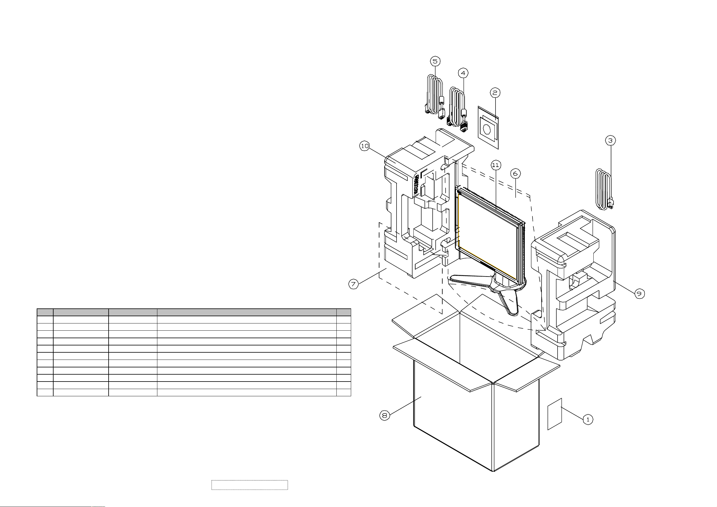
2-1 Package Overview
PACKING PARTS LIST (VP171-1)
Item ViewSonic P/N Ref. P/N Description Q'ty
1 M-LB-0813-0706 35.58203.001 LABEL CARTON 76*76mm 1
2 A-CD-VP171S
3 A-PC-0106-0272
4 A-VC-0101-0261
5 A-VC-0101-0262
6 M-MS-0808-9551 51.00081.004 PE BAG LDPE 540*750*0.07t W/HOLE 1
7 M-MS-0808-8952 51.58314.001 LCD PROTECT FILM 355*290*0.1t mm MYLAR VG700/VG750 1
8 P-BX-0601-0834 55.61101.007 CARTON AB-18 465*265*430(h) VP171s (EG01)
9 P-FM-0602-0583 56.61101.001 CUSHION R EPS VP171 1
10 P-FM-0602-0584 56.61102.001 CUSHION L EPS VP171 1
11 B-00000181 DC.61110.001 D.C. VP171s AUO M170 EG01 V0 1
36.61101.003 USER GUIDE+CD VP171s AUEG01 V0
42.50115.001 CABLE POWER CORD 1830mm SP30+IS14
42.59901.003 CABLE VGA 15P 1800mm 2*25mm CORE
42.59902.012 CABLE DVI-D 1.8M 2-CORE MOLEX
1
1
1
1
1
ViewSonic Corporation Confidential
4
-
Do Not Copy VP171s/b-1
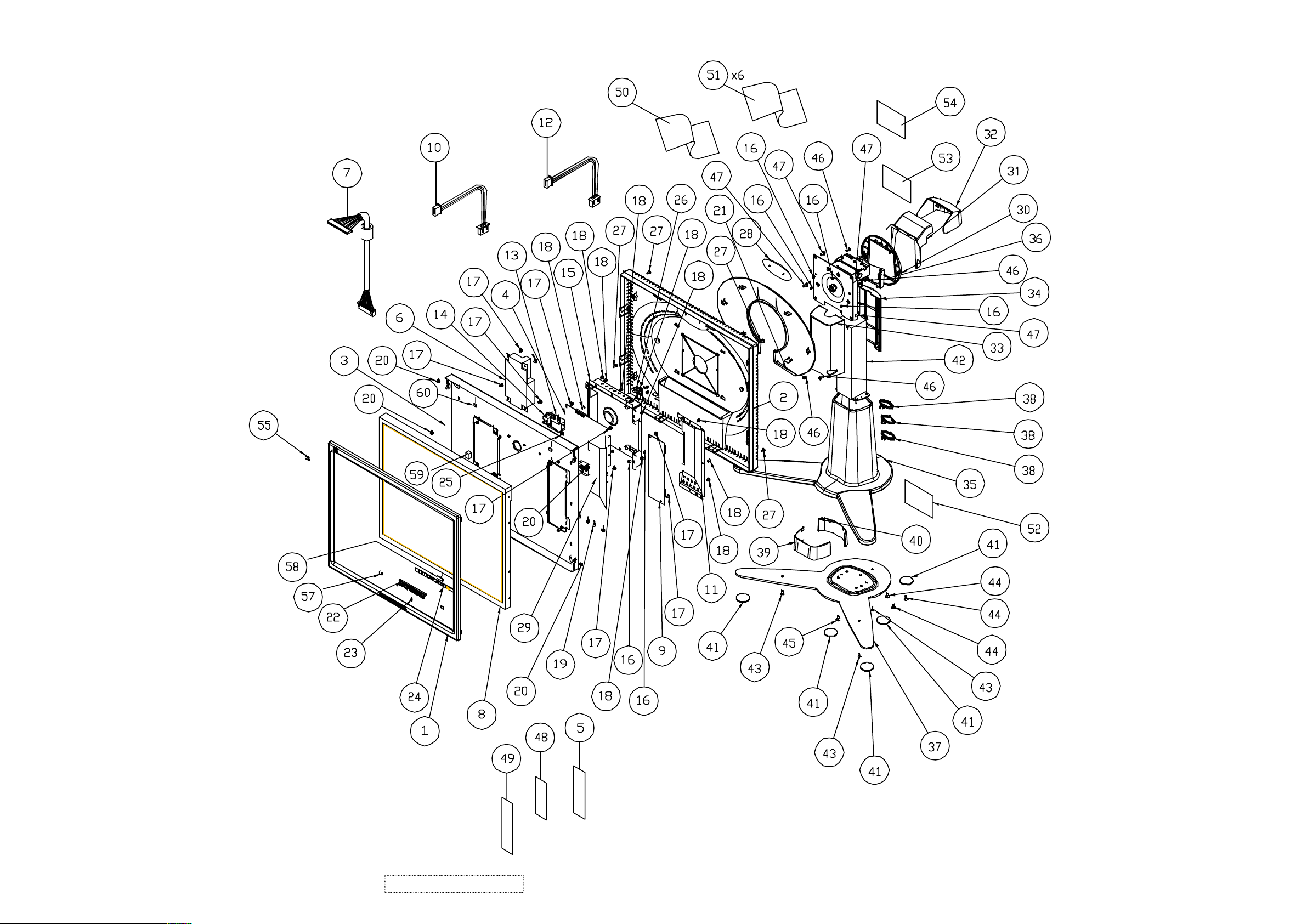
2-2 Exploded Overview
ViewSonic Corporation Confidential
5
-
Do Not Copy VP171s/b-1
2-3 Mechanical Spare Parts List.
ViewSonic Model Number: VLCDS25972
Rev: 1a
Item ViewSonic P/N Ref. P/N Description Q'ty
1 C-FP-0301-0357 51.61101.003 FRONT COVER PC+ABS-VS07A VP171s 1
2 C-BC-0302-0508 51.61102.003
3 HW-00000173 61.61101.002
4 B-MB-0201-0759 80.61104.001
5 M-00000174 35.61204.003
6 B-PS-0204-0057 44.61103.003 OPEN FRAME IN:100-240V OUT:12V/4.16A"LSE"(NOISE REDUCTION) 1
7 CB-00000175 42.61103.A01 W.A. 30P UL20276 #28110mm W/O CORE VP171(COSTDOWN) 1
8 M-LCD-0826-0256 48.62701.004 TFT LCD 17" AUO M170EG01 V.0 1
9 B-SB-0221-0700 44.58402.002 PCBA INVERTER;EMAX FOR 17" AUO M170EG01 V0 1
10 M-WR-0828-0717 42.61203.001 W.A. 4P UL1007 #24 250mm VP191(POWER) 1
11 PL-00000176 61.61102.001 SHIELDING PLATE-INV Tineplate 0.3t VP171 1
12 M-WR-0828-0716 42.61202.001 W.A. 10/6P UL1007 #24 50mm VP191(INV) 1
13 M-WR-0828-0718 42.61204.001 W.A. 4P UL1007 #18 VP191(SWT) 1
14 M-WR-0828-0719 42.61205.001 W.A. 3P UL1007 #18 50mm VP191(INLET) 1
15 M-MS-0808-9553 61.61202.001 SHIELDING BRKT-MB SECC 1.0t VP191 1
16 M-SCW-0824-6753 85.4A323.040 SCREW FLATE MECH M3*4 BLACK 7
17 M-SCW-0824-0651 85.1F123.060 SCREW PAN MECH W/SF M3*6 Ni 10
18 M-SCW-0824-6961 85.1H123.040 SCREW PAN MECH W/SPG M3*4 Ni 3
19 M-MS-0808-6287 85.005AG.075 SCREW HEX I/O #4-40*H5*L7.5 Ni NYLOK 6
20 HW-00000177 85.ZA123.040 SCREW WCH/W MECH M3*4 Ni 4
21 M-CV-0830-2452 51.61203.003 OVAL CAP PC+ABS-VS06A VP191s 1
22 PL-BT-0706-0166 51.61210.003 SELECT BUTTON PC+ABS-VS07A VP191s 1
23 M-MS-0808-9539 51.61211.001 LED LENS PMMA VP191 1
24 B-CB-0206-0158 80.61102.001 PCBA CTRL BD FOR VP171 1
25 M-SCW-0824-6827 85.1C124.060 SCREW PAN MECH W/T M4*6 Ni 1
26 M-BK-0805-0023 61.00042.001 LOCK BRKT+CAP SECC 0.8t 1
27 M-SCW-0824-6826 85.1F323.080 SCREW PAN MECH W/SF M3*8 BLACK 4
28 M-MS-0808-8116 51.58711.001 NAMEPLATE ELLIPSE ViewSonic 1
29 M-MS-0808-8750 51.61103.001 MYLAR ADHESIVEt=0.3mm VP171 1
30 M-CV-0830-0297 51.61204.003 HINGE CAP-1 PC+ABS-VS06 VP191s 1
31 M-CV-0830-0298 51.61205.003 HINGE CAP-2 PC+ABS-VS06 VP191s 1
32 M-CV-0830-2453 51.61206.003 HINGE CAP-3 PC+ABS-VS06 VP191s 1
33 M-MS-0808-8751 51.61207.003
34 M-MS-0808-8752 51.61208.003 REAR ARM PC+ABS-VS06 VP191s 1
35 M-CV-0830-2454 51.61209.003 BASE COVER PC+ABS-VS06 VP191s 1
36 M-CV-0830-2455 51.61212.003 HINGE CAP-4 PC+ABS-VS06 VP191s 1
37 M-MS-0808-8772 61.61204.001 BASE PLATE SPHC 3.0t Zn 1
38 M-MS-0808-8753 51.61213.003 CLIP NYLON-VS06 VP191s 3
39 M-MS-0808-7795 51.61214.001 WEAR PLATE (FRONT) VP191 1
40 M-MS-0808-7796 51.61215.001 WEAR PLATE (REAR) VP191 1
41 PL-PD-0714-0091 52.61201.001 RUBBER PAD 27d*2t VP191 4
42 HW-00000178 61.61104.001 HINGE VP171(CFT) 1
43 M-SCW-0824-0845 85.YA323.080 SCREW FLAT TAP M3*8 BLACK 3
44 M-SCW-0824-0869 85.4A624.080 SCREW FLAT MECH M4*8 BLACK NYLOK 4
45 M-SCW-0824-0868 85.4A623.080
46 M-SCW-0824-6755 85.UA123.080
47 M-SCW-0824-0847 85.5A124.080
48 M-MS-0808-8797 51.00014.002
49 M-MS-0808-8239 51.59901.001 ACETATE TAPE W=20mm 10cm
50 M-MS-0808-7798 41.53615.001 EMI Tape (80560) 30*50mm 2
51 M-MS-0808-7799 41.54612.001 EMI Tape (80560) 25*30mm 5
52 M-LB-0813-0736 35.58304.001 LABEL BARCODE 40*14 ViewSonic 1
53 M-LB-0813-0834 35.61101.006 LABEL SPEC 120*50mm VP171s(EG01) 1
54 M-LB-0813-0781 35.61203.001 LABEL BAR CODE 50*25mm VP191 1
55 M-MS-0808-7800 35.61202.001 BIRD LOGO AL E015-004 "ViewSonic" 1
56 M-00000174 35.61204.003 COSMETIC STRIP ADHESIVE 180*10*0.3(t)mm PC-VS06 VP191s 1
57 PL-00000180 52.61101.001 RUBBER 20L*10W*2.0T VP171 2
58 M-MS-0808-9913 52.61202.003 RUBBER KIT SILICONE 20*10*7.0mm 1
59 M-MS-0808-9914 52.61202.002 RUBBER KIT SILICONE 20*10*3.5mm 1
60 PL-00000181 52.59907.005 RUBBER PAD 15*10*1.7t mm 2
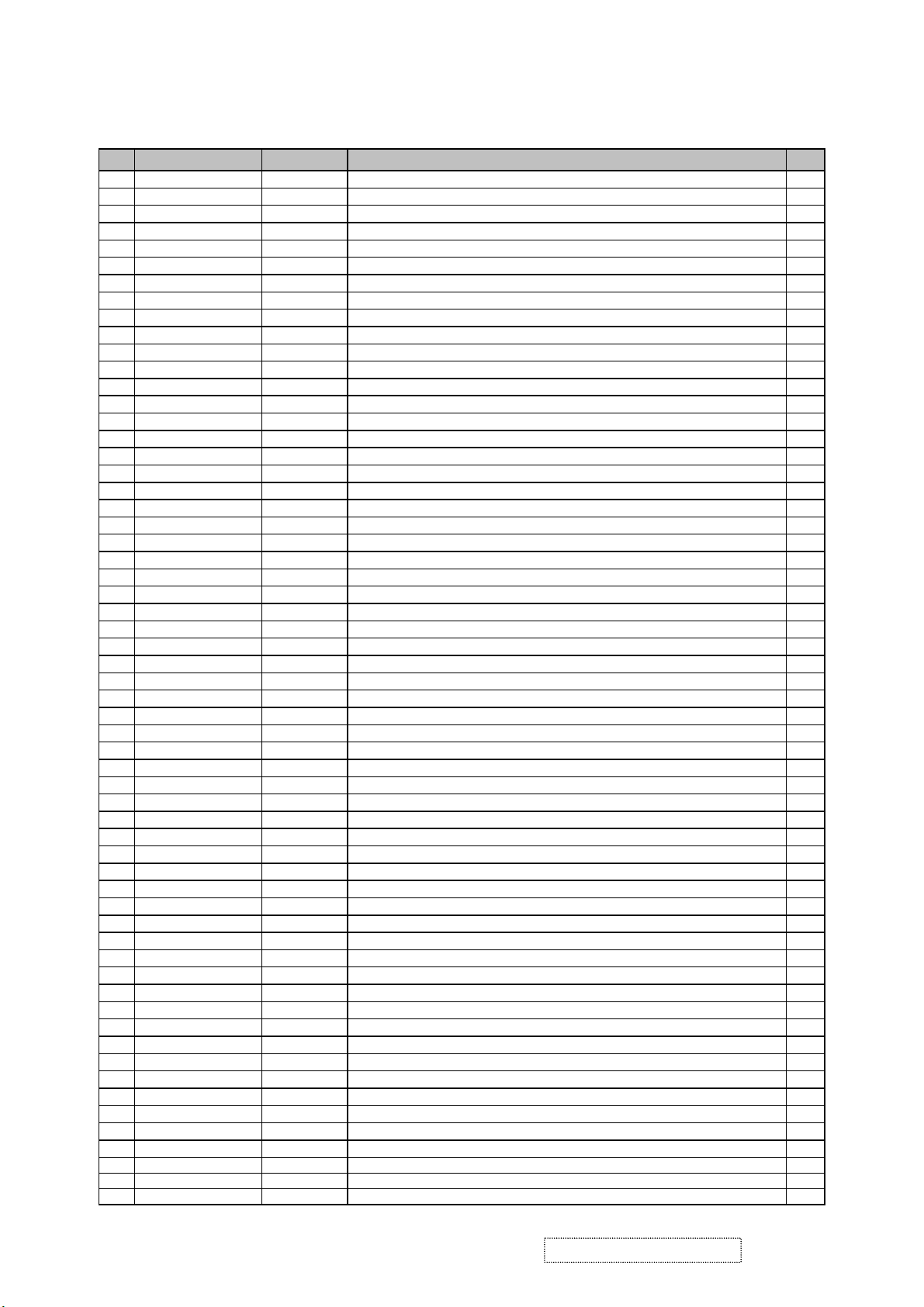
EXPLODED VIEW PARTS LIST
REAR COVER PC+ABS-VS06A VP171s
LCD BRKT SECC 1.0t AUO M170EG01 VP171
PCBA MAIN BD FOR VP171b AU EG01 V0
COSMETIC STRIP ADHESIVE 180*10*0.3(t)mm PC-VS06 VP191s
FRONT ARM PC+ABS-VS06 VP191s
SCREW FLAT MECH M3*8 BLACK NYLOK
DOUBLE THREADS SCREW PAN TAP M3*8 Ni
SCREW BINDING MECH M4*8 Ni
FILAMENT TAPE 3M NO.8915 25mm*55M
1
1
1
1
1
1
4
4
0.01
ViewSonic Corporation Confidential
6
-
Do Not Copy VP171s/b-1
3. Procedure of Disassembly
This section provides disassembly procedures for VP171/s/b LCD Monitor. Before you begin
any of these procedures, be sure to turn off the power, computer system, and other attached
devices; then disconnect the power cable from the electronically outlet. Moreover, when you
disassemble the monitor, be sure to put the screws in a safe place and separate them according
to grouping.
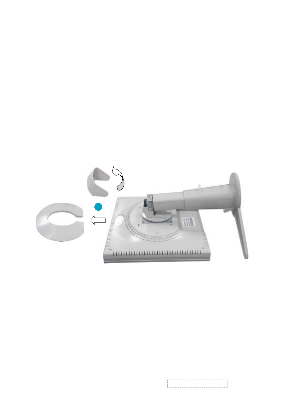
3-1 Disassembly of Stand unit from Monitor
Hinge Cap
Oval Cap
1
1. Put the monitor facedown. Take off Oval Cap and pry Hinge Cap off.
ViewSonic Corporation Confidential
7
-
Do Not Copy VP171s/b-1
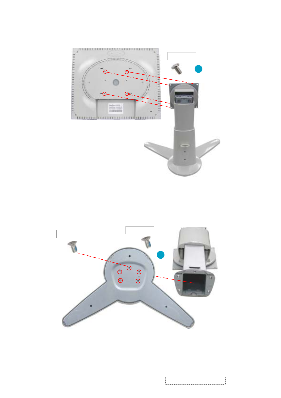
85.5A124.080
X 4
Stand unit
2. Unscrew five screws that secure Stand unit and detach Stand unit from the monitor.
2
85.4A123.080
X 1
3. Unscrew four screws of Base Plate to remove Hinge.
85.4A524.080
Base Plate
X 4
3
Hinge
ViewSonic Corporation Confidential
8
-
Do Not Copy VP171s/b-1
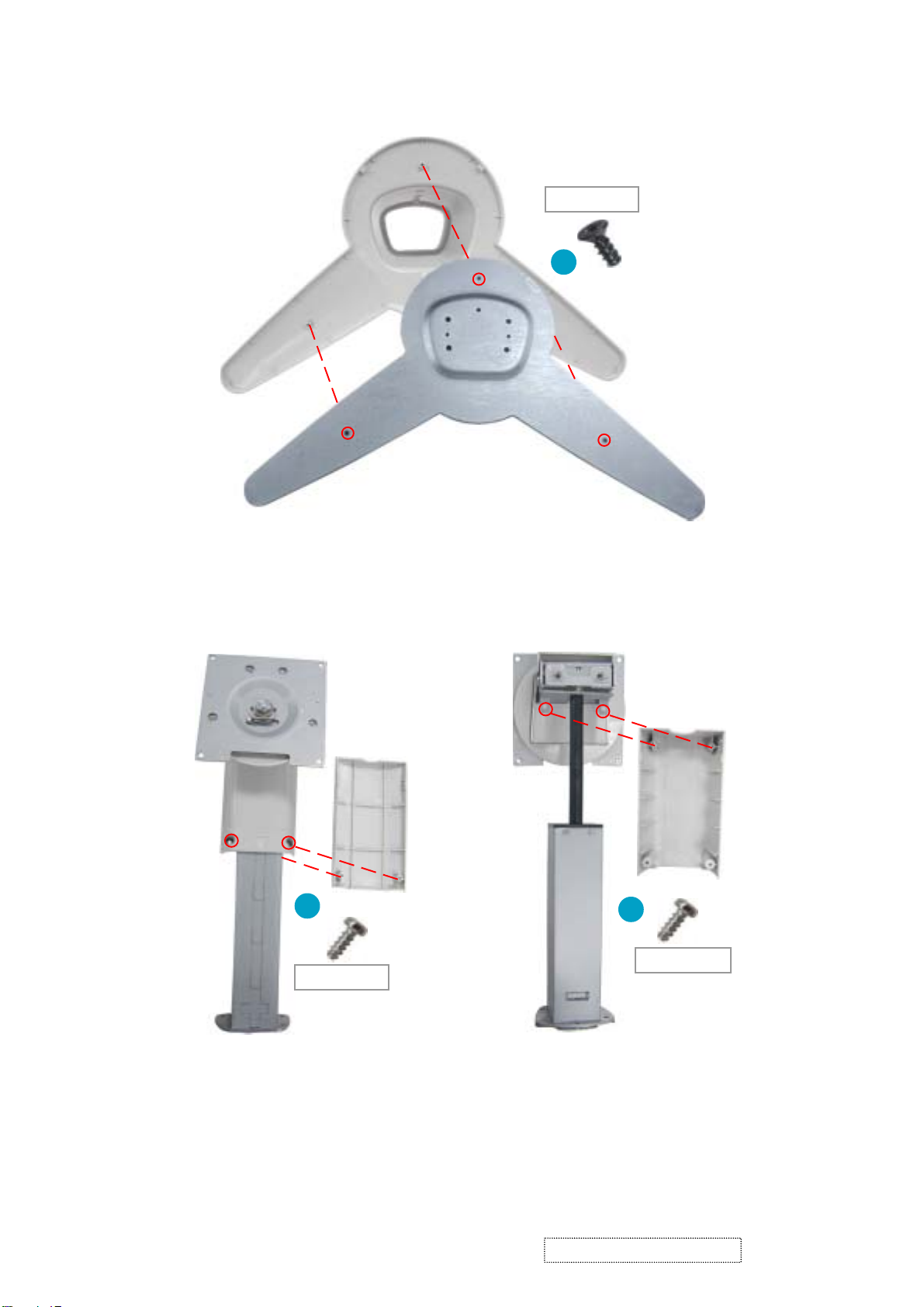
85.YA323.080
Base Cover
X 3
4
Base Plate
4. Unscrew three screws that secure Base Plate to separate Base Plate from Base Cover.
Front Arm
Rear Arm
5
X 2
Hinge
5. Unscrew two screws that secure Rear Arm to separate Rear Arm from Hinge.
6. Turn Hinge and unscrew two screws that secure Front Arm to detach Front Arm from Hinge.
85.UA123.080
Hinge
6
X 2
85.UA123.080
ViewSonic Corporation Confidential
9
-
Do Not Copy VP171s/b-1
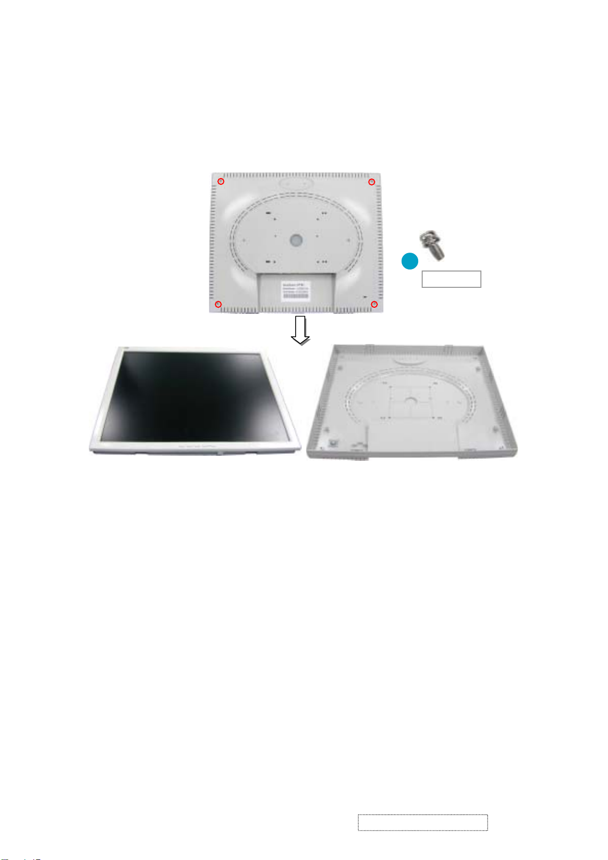
3-2 Disassembly of Rear Cover
Rear Cover
LCD Panel Module
X 4
1
85.1F123.080
Rear Cover
1. Unscrew four screws of Rear Cover, then detach LCD Panel module from Rear Cover.
ViewSonic Corporation Confidential
10
-
Do Not Copy VP171s/b-1
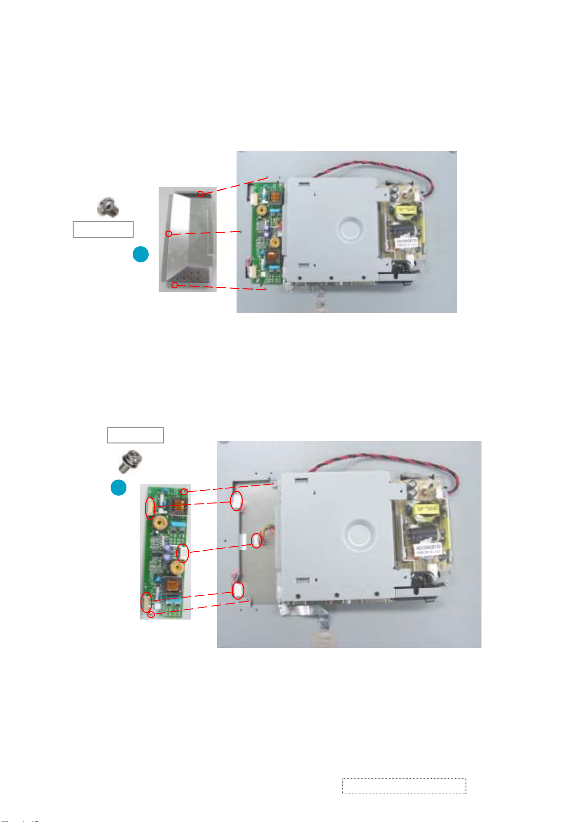
3-3 Disassembly of Inverter Board, Main Board and Power Board
X 3
85.AA123.030
1
Shielding Plate
1. Unscrew three screws that secure Shielding Plate and remove Shielding Plate.
85.1F123.060
X 2
2
Inverter Board
2. Unscrew two screws that secure Inverter Board and disconect three connectors to remove Inverter Board.
ViewSonic Corporation Confidential
11
-
Do Not Copy VP171s/b-1

X 7
3
85.AA123.030
M/B Shielding Bracket
85.4A323.040
3. Disconnect the wire between M/B and Power Board.
4. Unscrew 10 screws that secure M/B Shielding Bracket and Remove the EMI tape to remove M/B Shielding
Bracket.
X 3
4
EMI Tape
7
Main Board
85.005AG.075
5. Unscew six hex screws that secure Main Board.
6. Unscrew four screws that secure Main Board to remove Main Board.
7. Disconnect the wires which are connected to Main Board.
X 6
85.1F123.060
5
X 4
6
ViewSonic Corporation Confidential
12
-
Do Not Copy VP171s/b-1
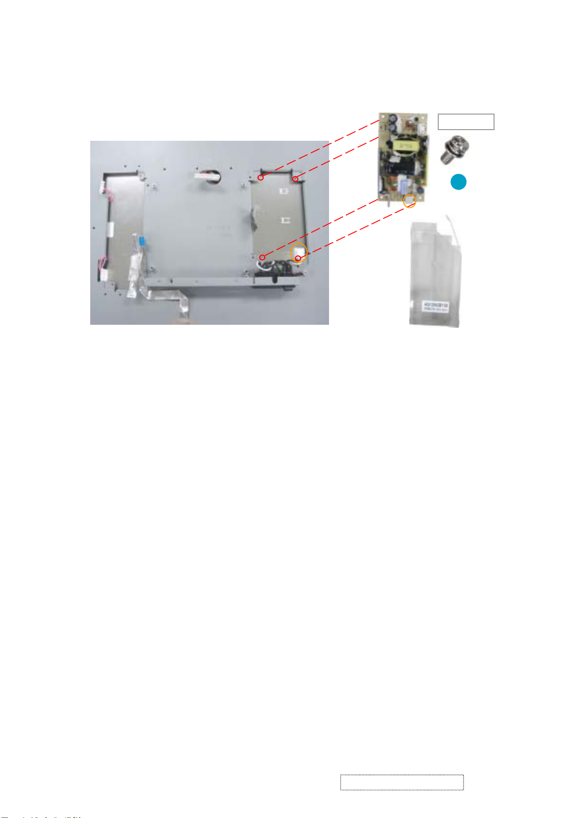
Power Board
85.1F123.060
8
Power Board Mylar
8. Unscrew four screws that secure Power Board and disconnect the wire to remove Power Board.
Detach Power Board Mylar.
X 4
ViewSonic Corporation Confidential
13
-
Do Not Copy VP171s/b-1
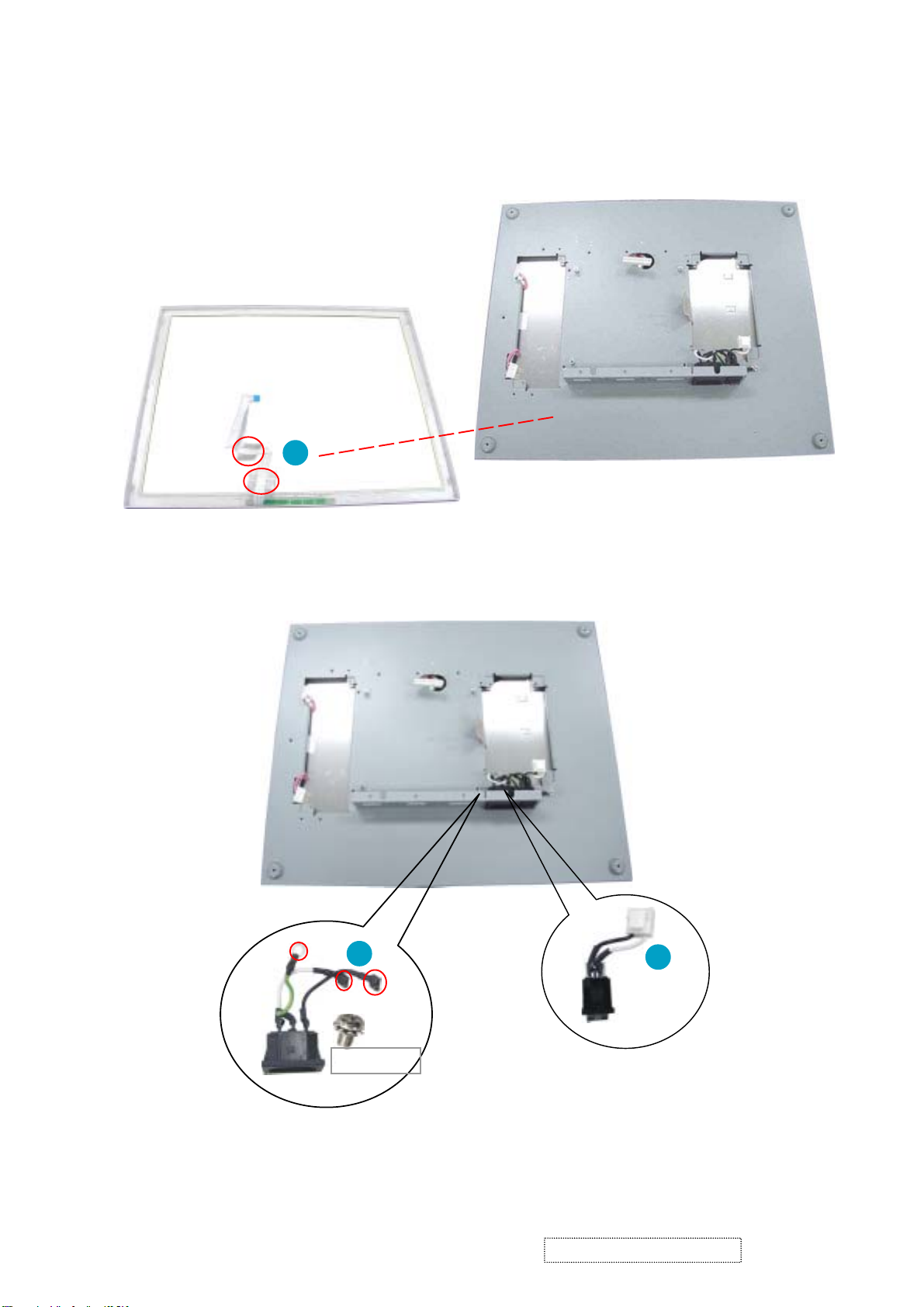
3-4 Disassembly of Front Cover Module, LCD Panel, Switch
and Inlet Wires
Front Cover
Control Board wire
1
1. Remove two tapes of Control Board wire and detach Front Cover from LCD Bracket.
2
Switch
Wire
X 1
85.1C124.060
Inlet Wire
2. Unscrew one screw that secures Inlet Wire and disconnect two wires that are connected to Switch Wire.
3. Use the tool to pull and press out Inlet and Switch Wires.
ViewSonic Corporation Confidential
14
3
-
Do Not Copy VP171s/b-1
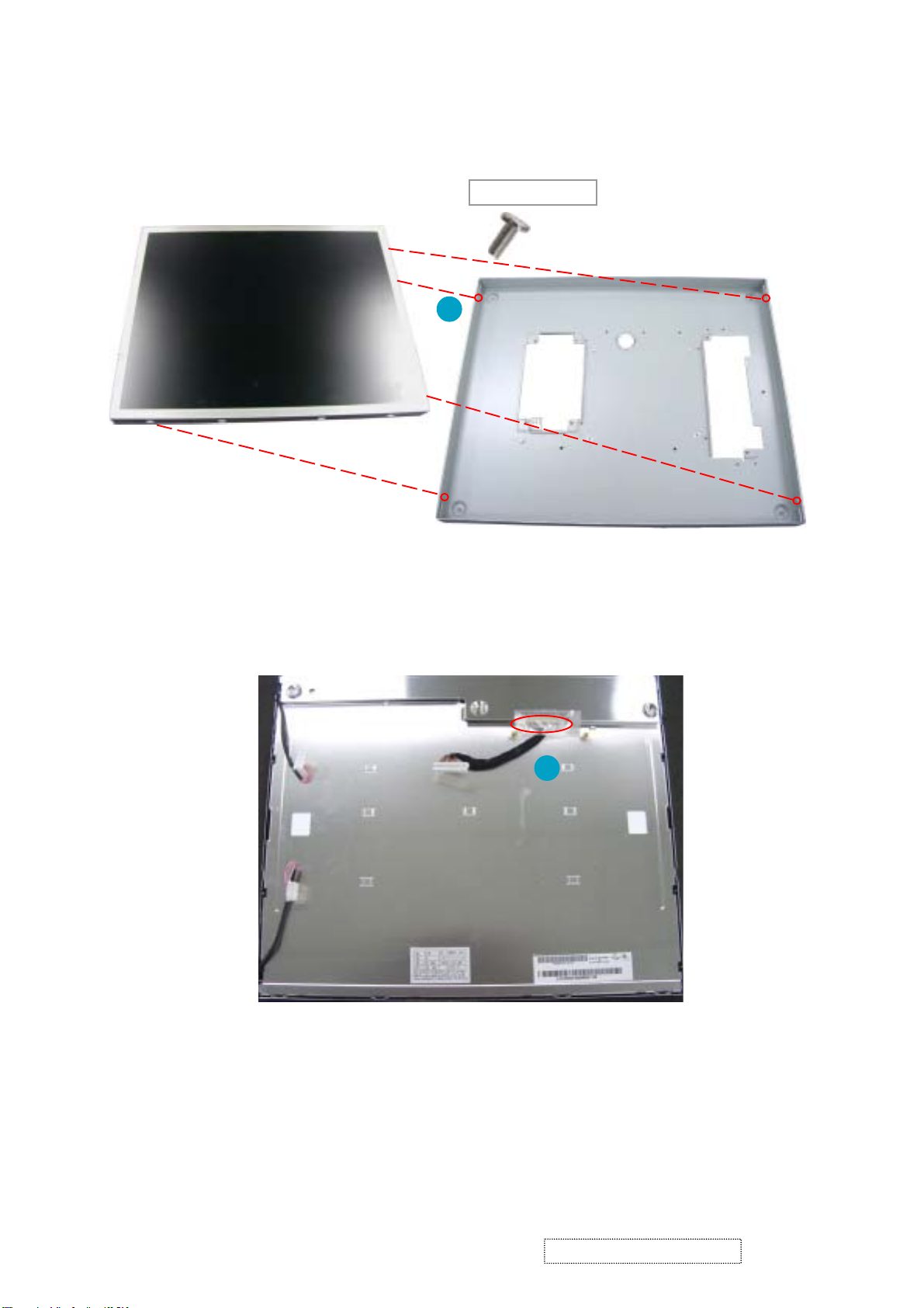
LCD Panel
85.ZA123.040
X 4
4
4. Unscrew four screws beside LCD Bracket to detach LCD Panel from LCD Bracket.
LCD Bracket
5
5. Turn LCD Panel around and remove the tape on the wire to disconnect the wire.
ViewSonic Corporation Confidential
15
-
Do Not Copy VP171s/b-1
4. Troubleshooting Procedure
This chapter provides technicians and people who have an electronic background a pri-
mary description about maintaining the product. Moreover, you can get the appropriate opera-
tion to solve some complicated problems of component repairing and professional problems.
4-1 Equipment Needed
- VP171 Monitor
- Philips Screw Driver #101 and #107
- Electronic Hex Nut M5mm
- PC(Personal Computer) with SXGA resolution / Pattern Generator
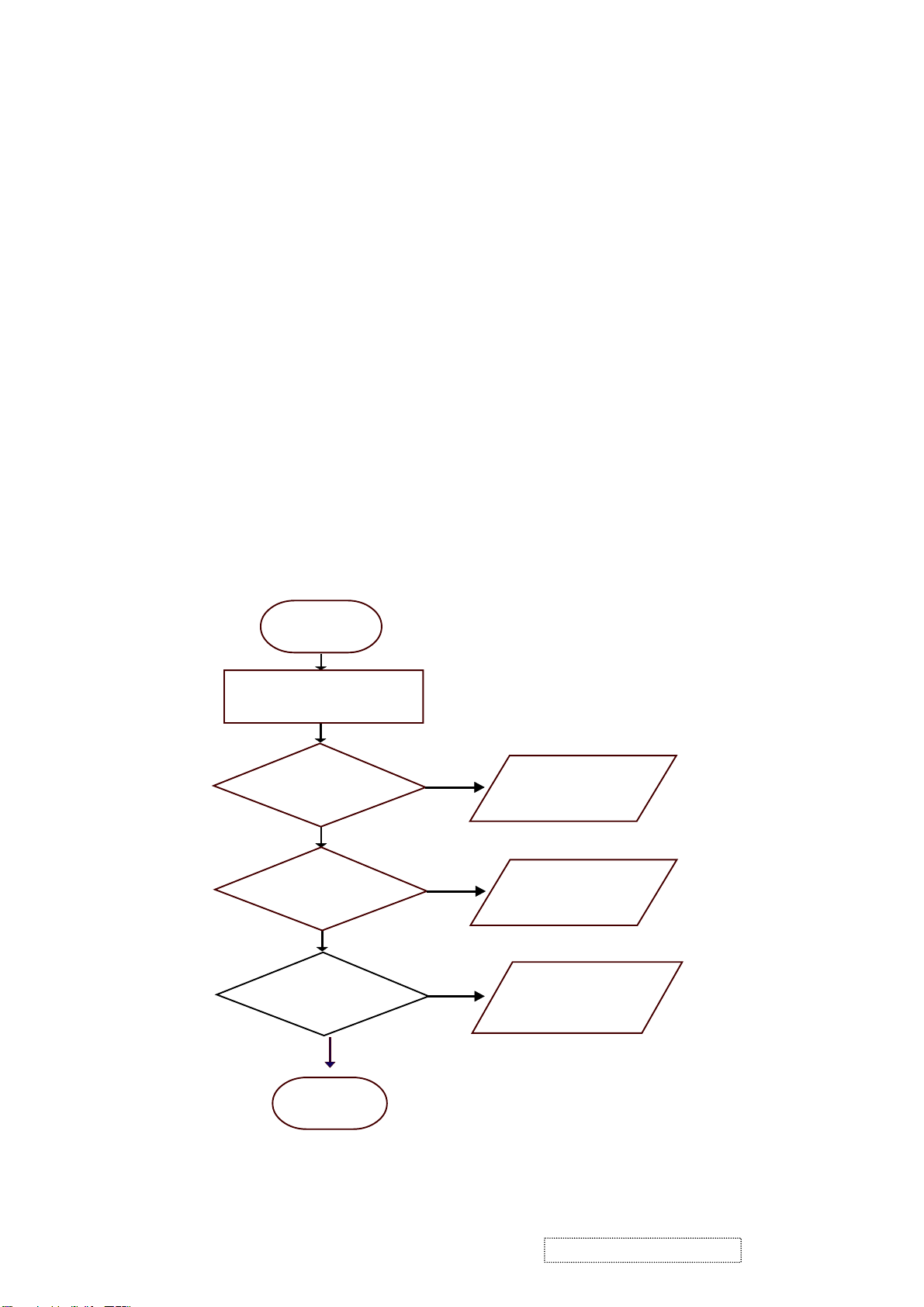
4-2 Main Procedure
Start
Power-on
Power LED ok ?
Ye s
Is display
performance ok ?
Yes
Is function
adjustment ok ?
No
No
No
A. Power Circuit
Troubleshooting
B. Performance
Troubleshooting
C. Control Function
Troubleshooting
Yes
End
ViewSonic Corporation Confidential
16
-
Do Not Copy VP171s/b-1
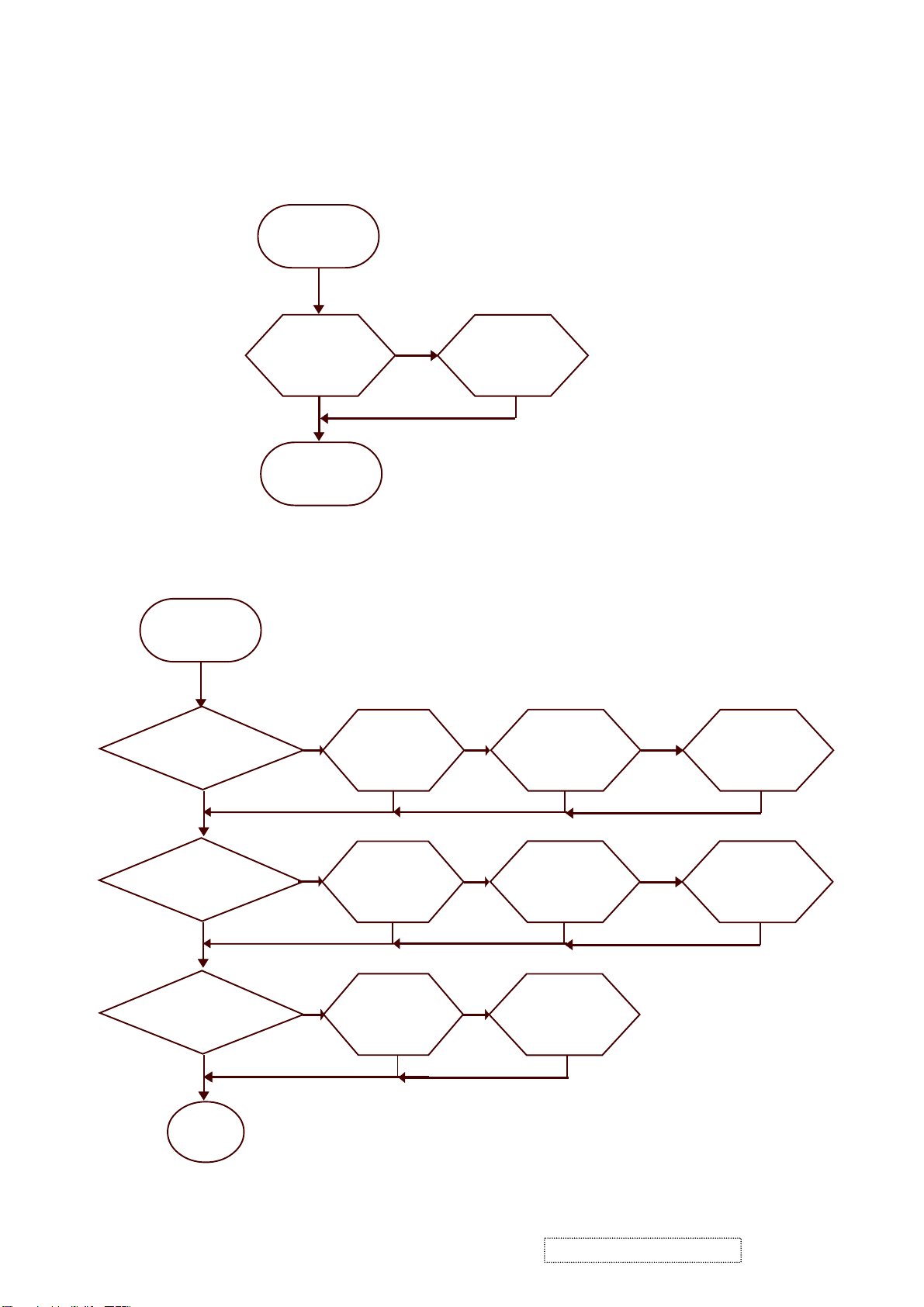
4-2.1 A. Power Circuit Troubleshooting
Start
Change
Power
Board
Yes
End
No
Change
Main Board
Yes
4-2.2 B. Performance Troubleshooting
Start
Is screen black ?
Yes
Change
Inverter Board
No
Change
Main Board
No
Change
LCD Panel
No
Is screen white ?
Ye s
Replug/Change
No
Abnormal Color ?
No
1
ViewSonic Corporation Confidential
Ye s
Yes
FPC Cable
Yes
Change
Main Board
Yes
No
No
17
Yes
Change
Main Board
Yes
Change
LCD Panel
Yes
Ye s
No
-
Do Not Copy VP171s/b-1
Change
LCD Panel
Yes
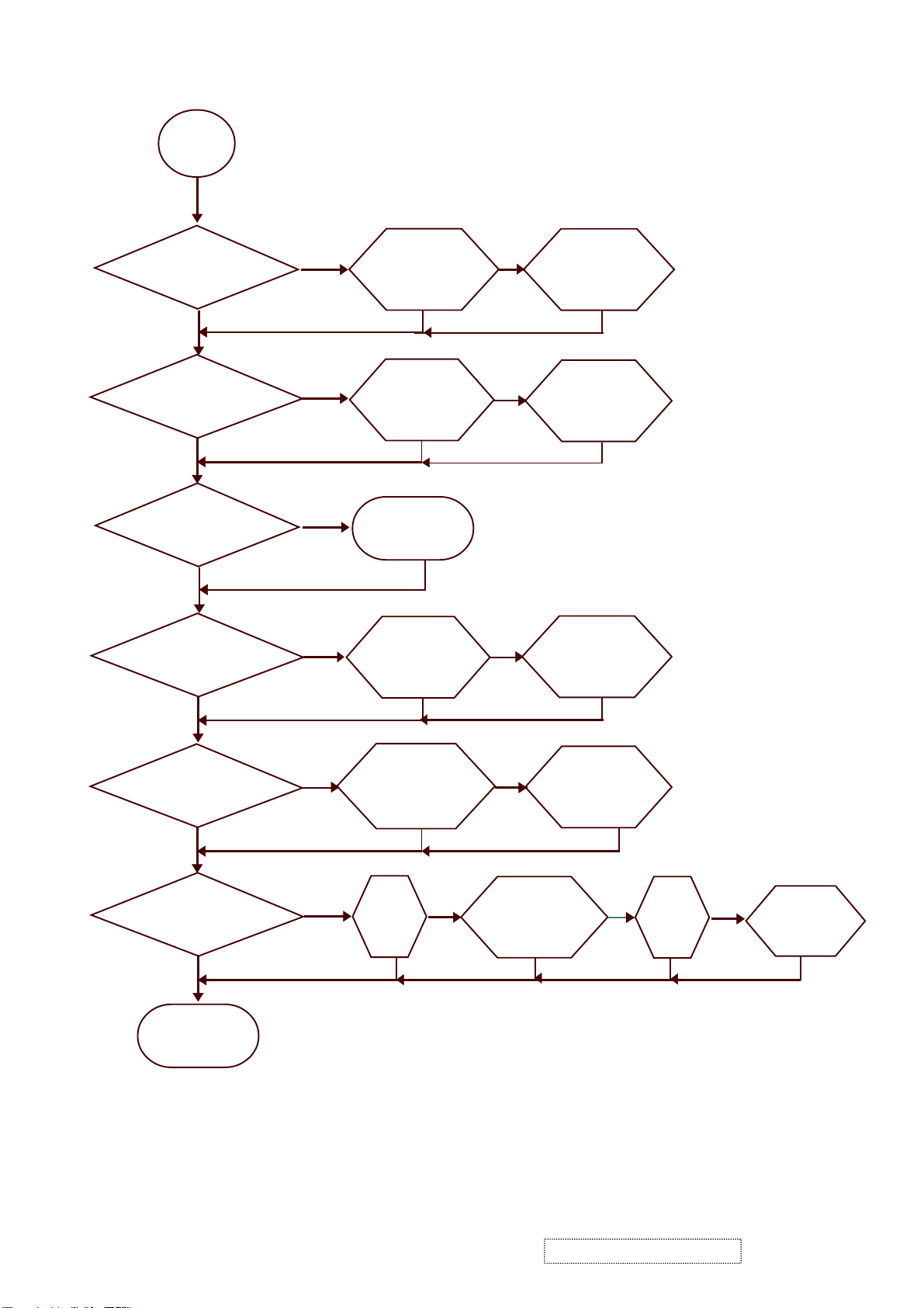
1
Is screen scrolling ?
No
Is screen flickering ?
No
Is LCD line defective ?
No
Bad Uniformity ?
Ye s
Yes
Yes
Ye s
Change
VGA Cable
Yes
Change
Main Board
Yes
Change
LCD Panel
Yes
Change
Inverter Board
No
No
No
Change
Main Board
Yes
Change
LCD Panel
Yes
Change
LCD Panel
No
Yes
Yes
Adjust Fine
Have line bar or noise?
Yes
Tune Sharpness or Auto
No
Change
Main Board
Adjustment
No
Ghost image ?
Yes
Refer to
Notice 1
Yes
No
Adjust Fine
Tune Sharpness or Auto
No
Ye s
Refer to
Notice 2
No
Change
Main Board
Adjustment
No
Yes
Yes
Yes
Yes
End
Notice :
1. Make sure VGA cable connect to PC directly and not through a Data transfer or Distribution......After this
action if Ghost image disappear, go to Yes; else, go to No.
2. Check the compatibility on the computer. If it is compatibility problem, feedback the information to ViewSonic;
else, go to No.
ViewSonic Corporation Confidential
18
-
Do Not Copy VP171s/b-1
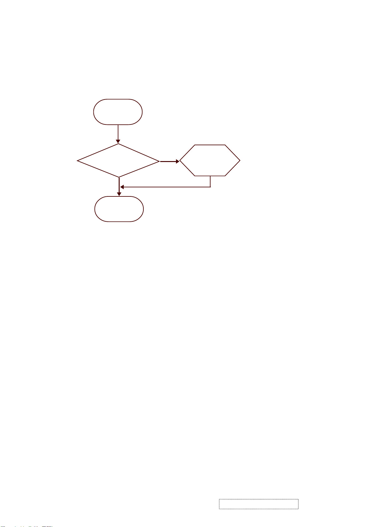
4-2.3 C. Control Function Troubleshooting
Start
Change
Control Board
Yes
End
No
Change
Main Board
Ye s
ViewSonic Corporation Confidential
19
-
Do Not Copy VP171s/b-1
5. Function Test and Alignment Procedure
5-1
5-2
5-3
Product
- 17 LCD Monitor
Test Equipment
- Color Video Signal & Pattern (or PC with SXGA resolution)
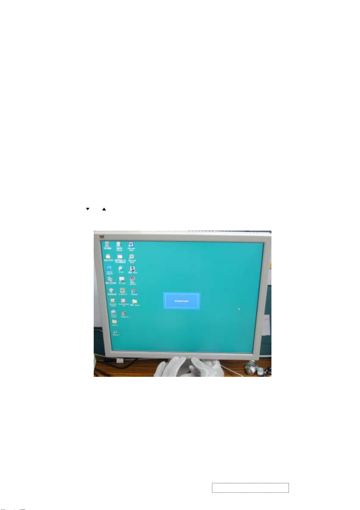
Hot Key
1). All Mode Reset:
Press , buttons simultaneously and Power on with signal, hold on for 3 seconds. Then the
screen will show All Mode Reset.
ViewSonic Corporation Confidential
20
-
Do Not Copy VP171s/b-1
 Loading...