

Page 1

Service Manual
ViewSonic VE710b/s-1
Model No. VLCDS27998-2W/-1W
17” Color TFT LCD Display
ViewSonic
(VE710b/s_1_SM_736- Rev. 1a – Dec. 2003)
381 Brea Canyon Road, Walnut, California 91789 USA - (800) 888-8583
Page 2
Copyright
Copyright
reproduced, transmitted, transcribed, stored in a retrieval system, or translated into any language or
computer language, in any form or by any means, electronic, mechanical, magnetic, optical, chemical,
manual or otherwise, without the prior written permission of ViewSonic Corporation.
Disclaimer
ViewSonic makes no representations or warranties, either expressed or implied, with respect to the
contents hereof and specifically disclaims any warranty of merchantability or fitness for any particular
purpose. Further, ViewSonic reserves the right to revise this publication and to make changes from time
to time in the contents hereof without obligation of ViewSonic to notify any person of such revision or
changes.
Trademarks
Optiquest is a registered trademark of ViewSonic Corporation.
ViewSonic is a registered trademark of ViewSonic Corporation.
All other trademarks used within this document are the property of their respective owners.
2003 by ViewSonic Corporation. All rights reserved. No part of this publication may be
¤
Revision History
Revision Date Description Of Changes Approval
1a 25/12/03 Initial Release DCN- 3742 Angela Luh
ViewSonic Corporation Confidential
i
-
Do Not Copy VE710b/s-1
Page 3

TABLE OF CONTENTS
1. Precautions and Safety Notices
2. Specification
3. Front Panel Function Control Description
4. Circuit Description
5. Adjusting Procedure
6. Trouble Shooting Flow Chart
7. Recommended Spare Parts List
8. Exploded Diagram And Spare Parts List
9. Block Diagram
10. Schematic Diagrams
11. PCB Layout Diagrams
1
2
3
5
15
18
20
28
32
33
42
ViewSonic Corporation Confidential
ii
-
Do Not Copy VE710b/s-1
Page 4

1. Precaution & Safety Notice
WARNING!
This service information designed for experienced repair technicians only and is not designed for use by the
general public.
It does not contain warnings or cautions to avoid non-technical individuals of potential dangers in
attempting to service a product.
Products powered by electricity should be serviced or repaired only by experienced professional technicians.
Any attempt to service or repair the product or products dealt within this service information by anyone else
could result in serious injury or death.
1. Caution :
No modification of any circuit should be attempted . Service work should only be performed after you are
thoroughly familiar with all of the following safety checks and servicing guide line.
2. Safety Check :
Care should be taken while servicing this LCD display. Because of the high voltage used in the inverter circuit.
These voltage are exposed in such areas as the associated transformer circuits .
3
. LEAKAGE CURRENT HOT CHECK
3-1 Plug the AC cord directly into the AC outlet. Do not use an isolation transformer during this check.
3-2 Connect a 1500 ohm , 10 watt resistor , paralleled by a 0.15uF capacitor between each metallic part and a good
earth ground.
3-3 Use an AC voltmeter with 1000 ohm / volt or more
combination 1500 ohm resistor and 0.15uF capacitor.
3-4 Move the resistor connection to each exposed metallic part and measure the voltage.
3
-5 Reverse the polarity of the AC plug in the AC outlet and repeat the above measurement.
3-6 Voltage measured must not exceed 1.5 volt RMS, from any exposed metallic part to the ground. A leakage
current tester may be used in the above hot check, in which case any circuit measured must not exceed 1.0
milliamp. In the case of a measurement exceeding the 1.0 milliamp value, a rework is required to eliminate the
chance of a shock hazard .
AC VOLTMETER
sensitivity and measure the AC voltage across the
V
0.15u
.
ViewSonic Corporation Confidential
To Metal Parts
1500 10W
1
Earth Ground
-
Do Not Copy VE710b/s-1
Page 5

2. Specification
Mechanical :
Dimension ( W x H x D ) mm
Set : a. with stand: 377.6 x 374 x 195.6 mm
b. Without stand: 377.6 x 311.8 x 56.9 mm
Slim bezel: 19.0 / 19.0 / 19.0/21.0
Base (L X W): 195.6 x 201 mm
Packing : ( W x H x D ) mm: 450 x 522 x 135 mm
Weight : Net / Gross ( Kg ): 4.1 / 5.2
Wall Mount (VESA): 100 x 100 mm
LCD Panel type: CPT / CLAA170EA03
Max. resolution (HxV): 1280 x 1024
Nominal picture size (HxV): 338 mm x 270 mm
Display colors: 16.2 M ( 6 bit + dithering )
Dot pitch: 0.264 mm
Response time: 9 +16 / 25ms (Tr + Tf / typical)
Brightness (100% white): Typical : 300 cd/m² , Min. 240 cd/m²
Contrast: Typical : 450:1, Min. 360:1
Viewing angle: 70 / 70 /65 / 65 (L/R/T/B CR>=10)
Synchronization: Fh = 30~80 KHz / Fv=50~85Hz
Presets: 18 timing modes
OSD Language: 9 languages
Color Temperatures RGB: 6500°K (default) / 9300°K 5400°K / User R,G,B
Plug & Play: DDC1/2B interface
Scaler chip: Mstar MST8116a
AC Power range: 90 V ~ 264 V, 50 Hz / 60 Hz
Power consumption: < 45W green / < 1W amber
(On / Off mode)
ViewSonic Corporation Confidential
2
-
Do Not Copy VE710b/s-1
Page 6
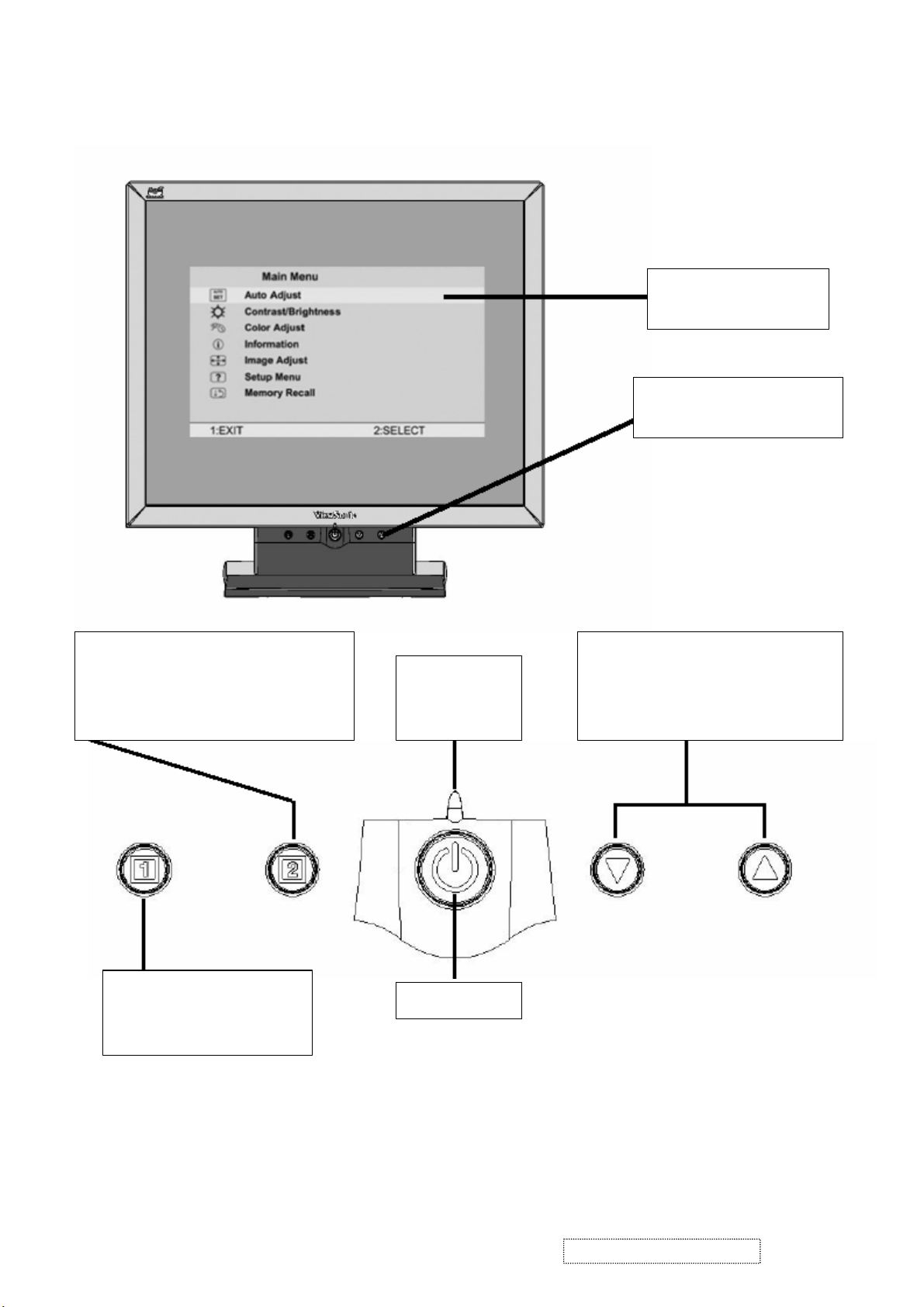
3. Front Panel Function Control Description
Main Menu
With OSD controls
Front Control Panel
shown below in detail
Displays the control screen for the
highlighted control. Also toggles
between two controls on some screens.
Also a shortcut to auto image adjust
Displays the Main Menu or
exits the control screen
and saves adjustments.
Power light
Green = ON
Orange =
Power Saving
Power On / Off
Scrolls through menu options and
adjusts the displayed control.
Also a shortcut to display the
Contrast adjustment control screen.
ViewSonic Corporation Confidential
3
-
Do Not Copy VE710b/s-1
Page 7

Main Menu Controls
Adjust the menu items shown below by using the up and down buttons.
A. Auto Image Adjust automatically sizes, centers, and fine tunes the video signal to eliminate waviness and
distortion. Press the [2] button to obtain a sharper image.
NOTE: Auto Image Adjust works with most common video cards. If this function does not work on your
LCD display, then lower the video refresh rate to 60 Hz and set the resolution to its pre-set value.
B. Contrast adjusts the difference between the image background (black level) and the foreground (white
level).
C. Brightness adjusts the lamps current to control the screen brightness.
D. Color Adjust
you to adjust red (R), green (G), and blue (B). The factory setting for this product is 6500K (6500° Kelvin).
9300K — Adds blue to the screen image for cooler white (used in most office settings with fluorescent
lighting).
5400K — Adds red to the screen image for warmer white and richer red.
Custom User Color — Individual adjustments for red, green, and blue.
1 To select color (R, G or B) press button [2].
2 To adjust selected color, press or .
3 When you are finished making all color adjustments, press button [1] twice.
provides several color options: preset color temperatures and Custom User Color which allows
E. Information displays the timing mode (video signal input) coming from the graphics card in your computer.
See your graphic card’s user guide for instructions on changing the resolution and refresh rate (vertical
frequency). VESA 1280 x 1024 @ 60 Hz (recommended) means that the resolution is 1280 x 1024 and the
refresh rate is 60 Hertz.
F. Manual Image Adjust
H. Size (Horizontal Size) adjusts the width of the screen image.
NOTE: Vertical size is automatic with your LCD display.
H./V. Position adjusts horizontal and vertical position of the screen image. You can toggle between
Horizontal and Vertical by pressing button [2]. Horizontal move s the screen image to the left or to the right.
Vertical moves the screen image up and down.
Fine Tune sharpens focus by aligning the illuminated text and/or graphic characters.
Sharpness adjusts the clarity and focus of the screen image.
Setup Menu controls are explained below:
Language allows you to choose the language used in the menus and control screens.
Resolution Notice displays the recommended resolution for this LCD display.
Enable allows the Resolution Notice to appear on-screen.
Disable will not allow the Resolution Notice to appear on-screen.
OSD Timeout sets the length of time an on-screen display screen is displayed. For example, with a“15
G. OSD Position allows you to move the on-screen display menus and control screens.
H. Memory Recall
Preset Timing Mode listed in this user guide.
controls are explained below:
second” setting, if a control is not pushed within 15 seconds, the display OSD
disappears.
returns adjustments to the original factory settings if the display is operating in a factory
ViewSonic Corporation Confidential
4
-
Do Not Copy VE710b/s-1
Page 8
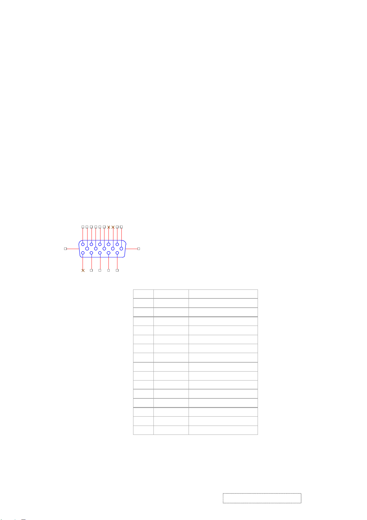
PIN
MNEMONI
SIGNAL
1RVRed Video
2GVGreen Video
3BVBlue Video
4NCNone5GND
Ground(DDC return)
6RGRed GND
7GGGreen GND
8BGBlue GND
9
+5V
+ 5V (for DDC)
10SGSync GND
11NCNone
12
SDA
DDC Data
13HSHorizontal Sync
14VSVertical Sync
15
SCL
DDC Clock
4. Circuit Description
4-1. Outline
POWER On/Off , LED, Button"2" , Up arrow- button , Down arrow button , Button"1" , button , Down arrow
button , Button"1" , on the front panel.
Video signal connector, audio line-in receptacle and AC-IN are located on the back side of the cabinet.
l OSD menu includes the following function;
AUTO IMAGE ADJUST
CONTRAST / BRIGHTNESS
COLOR ADJUST
INFORMATION
MANUAL IMAGE ADJUST
SETUP MENU
MEMORY RECALL
l CONTRAST and BRIGHTNESS can be directly controlled with UP / DN key.
4-2. CONNECTORS
l AC inlet : CEE22 typed connector
l Video signal connector 15P Mini D-Sub
162738495
16 17
11
121314
CN6
10
DB15HD
15
ViewSonic Corporation Confidential
-
Do Not Copy VE710b/s-1
5
Page 9

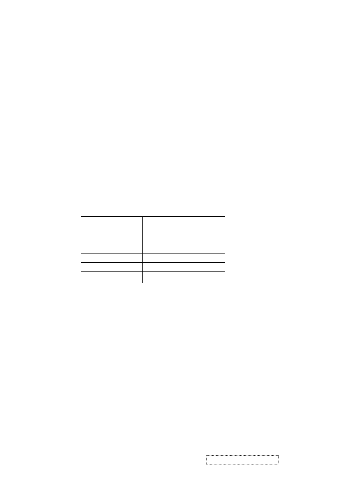
4-3. ELECTRICAL SPECIFICATIONS
l Standard conditions
Display Area 338 x 270 mm
Video Signal 0.7 Vpp
Contrast Max.
Brightness Max.
l
Ambient
Input AC
Warming up > 30 min
Display 1280 x 1024
POWER
- Power supply
Input Voltage 90 -240 ~Volts
Power Frequency
Input current
Inrush current 90A(max.) at 230Vac
Power consumption 50Watt
Output Voltage @0-4.8A load 12Vdc
- Power Management
State Power Indicator
20 +/- 5 °C
50/ 60 Hz +/-3Hz
<1.5Arms @ 90Vac
<0.75Arms@265Vac
+/-5%
On 45Watt Green
Standby <1Watt Amber
Off <1Watt
l Acceptable timing
If your timing is within following specification, this LCD display can automatically function with a certain
position.
Horizontal: Sync frequency : 30~80 kHz
Vertical: Sync frequency : 50~85Hz
l Signal level and input impedance
- Video Signal level This LCD display is adjusted at the factory using 0,7 Vp-p Video signal.
- Sync Signal level
H/V Separate : TTL level
- Input impedance
Video input : 75 ohms
Sync input : > 1 k ohms
ViewSonic Corporation Confidential
-
6
Do Not Copy VE710b/s-1
Page 10

4-4. SIGNAL CABLE : Non-detachable cable with Mini D-Sub 15P connector at one end. Length : 1.8 meter.
4-5. EDID data
Analog EDID
Time: 09:08:54
Date: Wed Sep 04, 2002
______________________________________________________________________
______________________________________________________________________
VIEWSONIC CORPORATION
EDID Version # 1, Revision # 3
DDCTest For: VSC VE710s
______________________________________________________________________
______________________________________________________________________
0 | 00 FF FF FF FF FF FF 00 5A 63
10 | 18 F5 01 01 01 01 01 0D 01 03
20 | 08 22 1B 78 2E 04 A5 A3 58 4F
30 | 95 24 19 50 54 BF EF 80 81 80
40 | 81 40 71 4F 01 01 01 01 01 01
50 | 01 01 01 01 30 2A 00 98 51 00
60 | 2A 40 30 70 13 00 52 0E 11 00
70 | 00 1E 00 00 00 FF 00 41 33 33
80 | 30 33 30 31 30 30 30 30 31 0A
90 | 00 00 00 FD 00 32 4B 1E 50 0E
100 | 00 0A 20 20 20 20 20 20 00 00
110 | 00 FC 00 56 45 37 31 30 73 0A
120 | 20 20 20 20 20 20 00 98
____________________________________________________________________
(08-09) ID Manufacturer Name = VSC
(10-11) Product ID Code (Non-Alphanumerical) =
F518
(12-15) Last 5 Digits of Serial Number = NOT SPECIFIED
(16) Week of Manufacture = 01
(17) Year of Manufacture = 2003
(10-17) Complete Serial Number = NOT SPECIFIED
(18) EDID Structure Version Number = 1
(19) EDID Structure Revision Number = 3
(20) VIDEO INPUT DEFINITION : =
Separate Sync, Analog signal, 0.700V/0.300V (1.000 Vp-p)
(21) Maximum Horizontal Image Size = 340mm
(22) Maximum Vertical Image Size = 270mm
(23) Display Gamma = 2.20
(24) DPMS Supported Feature: = Active Off.
Display type = RGB color display
(25-34) CHROMA INFO:
Red x = 0.633 Green x = 0.300 Blue x = 0.146 White x = 0.313
Red y = 0.336 Green y = 0.586 Blue y = 0.103 White y = 0.329
ViewSonic Corporation Confidential
7
-
Do Not Copy VE710b/s-1
Page 11

(35) ESTABLISHED TIMING I:
720 x 400 @ 70Hz (VGA, IBM)
640 x 480 @ 60Hz (MAC II, Apple)
640 x 480 @ 67Hz (VESA)
640 x 480 @ 72Hz (VESA)
640 x 480 @ 75Hz (VESA)
800 x 600 @ 56Hz (VESA)
800 x 600 @ 60Hz (VESA)
(36) ESTABLISHED TIMING II:
800 x 600 @ 72Hz (VESA)
800 x 600 @ 75Hz (VESA)
832 x 624 @ 75Hz (MAC II, Apple)
1024 x 768 @ 60Hz (VESA)
1024 x 768 @ 70Hz (VESA)
1024 x 768 @ 75Hz (VESA)
1280 x 1024 @ 75Hz (VESA)
(37) Manufacturer's Reserved Timing:
1152 x 870 @ 75Hz (MAC II, Apple)
(38-53) Standard Timing Identification:
#1: 1280 x 1024 @60Hz
#2: 1280 X 960 @60HZ
#3: 1152 X 864 @75HZ
#4: (44) not specified
#5: (46) not specified
#6: (48) not specified
#7: (50) not specified
#8: (52) not specified
(54-71) Detail Timing Description #1: 1280x1024 Pixel Clock=108.0MHz
Horizontal Image Size=338mm Vertical Image Size=270mm
Refresh Mode: Non-Interlaced Normal display, no stereo
HORIZONTAL:
Active Time = 1280 pixels Blanking Time = 408 pixels
Sync Offset = 48 pixels Sync Pulse Width = 112 pixels
Border = 1 pixels Frequency = 64.0 kHz
VERTICAL:
Active Time = 1024 lines Blanking Time = 42 lines
Sync Offset = 1 lines Sync Pulse Width = 3 lines
Border = 0 lines Frequency = 60.0 Hz
Sync configuration: Digital separate, V(+), H(+)
ViewSonic Corporation Confidential
8
-
Do Not Copy VE710b/s-1
Page 12

(72-89) Monitor Description:
Monitor S/N: A33030100001
(90-107) Monitor Description:
Monitor Range Limits:
Vertical Frequency (min) = 50Hz
Vertical Frequency (max) = 75Hz
Horizontal Frequency (min) = 30Hz
Horizontal Frequency (max) = 82Hz
Maximum Supported Pixel Clock = 140MHz
(108-125) Monitor Description:
Monitor Name: VE710s
(127) Checksum OK
SECONDARY GTF - NOT SUPPORTED
Time: 14:35:05
Date: Thu Jul 03, 2003
______________________________________________________________________
______________________________________________________________________
VIEWSONIC CORPORATION
EDID Version # 1, Revision # 3
______________________________________________________________________
______________________________________________________________________
DDCTest For: ViewSonic VE710b
128 BYTES OF EDID CODE:
0 1 2 3 4 5 6 7 8 9
0 | 00 FF FF FF FF FF FF 00 5A 63
10 | 18 F6 01 01 01 01 01 0D 01 03
20 | 08 22 1B 78 2E 04 A5 A3 58 4F
30 | 95 24 19 50 54 BF EF 80 81 80
40 | 81 40 71 4F 01 01 01 01 01 01
50 | 01 01 01 01 30 2A 00 98 51 00
60 | 2A 40 30 70 13 00 52 0E 11 00
70 | 00 1E 00 00 00 FF 00 41 33 34
80 | 30 33 30 31 30 30 30 30 31 0A
90 | 00 00 00 FD 00 32 4B 1E 50 0E
100 | 00 0A 20 20 20 20 20 20 00 00
110 | 00 FC 00 56 45 37 31 30 62 0A
120 | 20 20 20 20 20 20 00 A7
_____________________________________________________________
ViewSonic Corporation Confidential
9
-
Do Not Copy VE710b/s-1
Page 13

(08-09) ID Manufacturer Name = VSC
(11-10) Product ID Code = F618
(12-15) Last 5 Digits of Serial Number = Not Used
(16) Week of Manufacture = 01
(17) Year of Manufacture = 2003
(10-17) Complete Serial Number = See Descriptor Block
(18) EDID Version Number = 1
(19) EDID Revision Number = 3
(20) VIDEO INPUT DEFINITION:
Separate Syncs, Analog singal, 0.700V/0.300V(1.000 Vp-p)
(21) Maximum Horizontal Image Size = 340 mm
(22) Maximum Vertical Image Size = 270 mm
(23) Display Gamma = 2.20
(24) Power Management and Supported Feature(s):
Active Off/Very Low Power, Standard Default Color Space,
Preferred Timing Mode
Display Type = R/G/B Color
(25-34) CHROMA INFO:
Red X - 0.637 Green X - 0.310 Blue X - 0.143 White X - 0.313
Red Y - 0.344 Green Y - 0.582 Blue Y - 0.100 White Y - 0.329
(35) ESTABLISHED TIMING I:
720 X 400 @ 70Hz (IBM,VGA)
640 X 480 @ 60Hz (IBM,VGA)
640 X 480 @ 67Hz (Apple,Mac II)
640 X 480 @ 72Hz (VESA)
640 X 480 @ 75Hz (VESA)
800 X 600 @ 56Hz (VESA)
800 X 600 @ 60Hz (VESA)
(36) ESTABLISHED TIMING II:
800 X 600 @ 72Hz (VESA)
800 X 600 @ 75Hz (VESA)
832 X 624 @ 75Hz (Apple,Mac II)
1024 X 768 @ 60Hz (VESA)
1024 X 768 @ 70Hz (VESA)
1024 X 768 @ 75Hz (VESA)
1280 X 1024 @ 75Hz (VESA)
(37) Manufacturer's Reserved Timing:
1152 X 870 @ 75Hz (Apple,Mac II)
ViewSonic Corporation Confidential
10
-
Do Not Copy VE710b/s-1
Page 14

(38-53) Standard Timing Identification:
1280 X 1024 @60Hz
1280 X 960 @60Hz
1152 X 864 @75Hz
Not Used
Not Used
Not Used
Not Used
Not Used
(54-71) Detailed Timing / Descriptor Block 1:
Horizontal Image Size: 338 mm Vertical Image Size: 270 mm
Refreshed Mode: Non-Interlaced Normal Display - No Stereo
Horizontal:
Active Time: 1280 pixels Blanking Time: 408 pixels
Sync Offset: 48 pixels Sync Pulse Width: 112 pixels
Border: 0 pixels Frequency: 63.98 KHz
1280x1024 Pixel Clock: 108.00 MHz
Vertical:
Active Time: 1024 lines Blanking Time: 42 lines
Sync Offset: 1 lines Sync Pulse Width: 3 lines
Border: 0 lines Frequency: 60.02 Hz
Digital Separate, Horizontal Polarity (+) Vertical Polarity (+)
(72-89) Detailed Timing / Descriptor Block 2:
Monitor Serial Number:
A34030100001
(90-107) Detailed Timing / Descriptor Block 3:
Monitor Range Limits:
Min Vertical Freq - 50 Hz
Max Vertical Freq - 75 Hz
Min Horiz. Freq - 30 KHz
Max Horiz. Freq - 80 KHz
Pixel Clock - 140 MHz
Secondary GTF - Not Supported
(108-125) Detailed Timing / Descriptor Block 4:
Monitor Name :
VE710b
(126) No Extension EDID Block(s)
(127) CheckSum OK
ViewSonic Corporation Confidential
11
-
Do Not Copy VE710b/s-1
Page 15
4-6. THEORY OF OPERATION
This section describes the function of the LCD monitor per functional block.
This monitor includes MB board, inverter board, adapter and button board.
l
MB Board
The MB board is a four-layer, single-landed design with ground and internal planes provided. DC power from the
power adapter enter the board through DC jack. Other connectors on the board are for inverter, audio and button
board .The VGA cable is a signal cable that contains video signal, sync signal and DDC signal from PC VGA
adapter. This system board consists of 4 functional areas : flat panel controller, flash ROM , power regulator and
Audio amplifier
l
Flat panel controller… MST8116A (U3)
The heart of the system board is mstar MST8116A. The MST8116A is a graphics processing IC for LCD
monitor. It provides all key IC functions required for LCD panel. On-chip functions include a high-speed
triple-ADC , PLL, high scaling engine, OSD controller and on -chip micro controller.
a) Clock Generation :
Crystal Input Clock (TCLK and XTAL). This is the input pair to an internal crystal oscillator and
corresponding logic. A 14.318 MHz crystal is recommended.
b) Analog to Digital Converter:
The MST8116A chip has three ADC's (analog-to-digital converters), one for each color (red, green and
blue) .The analog RGB signals are connected to
MST8116A as described
below
Pin Name Pin Number
Red + 63
Red - 62
Green + 60
Green - 59
Blue + 58
Blue - 57
c) OSD : The MST8116A has a fully programmable ,high-quality OSD controller. The on-chip static
RAM(4096 words by 24 bits) stores the cell map and the cell definitions.
d) MTV312 Micro controller: The MTV312 micro controller(MCU) serves as the system micro controller. It
programs the MST8116A and manages other devices in the system such as the keypad, the backlight, LED,
audio and non-volatile RAM. using general purpose input/output (GPIO) pins.
ViewSonic Corporation Confidential
12
-
Do Not Copy VE710b/s-1
Page 16

e) Panel Power Sequencing ( VDDCTRL1, 2) ( Pin 32, 3) : The MTV312 has two dedicated outputs
Pin number Pin Name Pin Number Usage
21 P1.3 Key / Power on ,off
13 P3.4 NV_RAM (U4) SDA
14 P3.5 NV_RAM (U4) SCL
25 P1.7 Key_down
9 P6.3 Key_right
24 P1.6 Key_up
16 P6.2 Key_left
37 P4.1 Key_mute
34 P5.6 VGA connector
23 P1.5 Key_select
42 P5.3 LED_red
41 P5.4 LED_green
32 P6.6 LCD panel power1 on / off control
3 P5.0 LCD panel power2 on / off control
36 P4.0 Backlight on / off control
VDDCTRL1 and 2 ( Pin32 and Pin3) to control LCD power sequencing once data and control signals
are stable.
f) Panel interface (Pin 1~25, Pin75~128) : The MTV312 driver interface is highly programmable. It supports
dual bus / dual port for SXGA drivers.
l
Power Regulator MC34063A (U6),AIC1739 (Q4) :
The MC34063A is a monolithic control IC containing the primary functions required for DC to DC
internal temperature converters. The device consists of an compensated reference, comparator, controlled duty
cycle. Oscillator with an active current sense circuit. Desired output voltage are determined by the equation,
Volt = 1.25 ( 1 + R67 / R66), In this case, the output voltage are 3.3 Volts
The AIC1739 is a low dropout positive adjustable regulator with minimum of 300mA output current capability.
So it is well suited for 3.3 V and 2.5 V Regulator.
4-7 Power/Inverter Board
This is a specific power/inverter for L7VC monitor 50W 12V 4.16A output power and backlight which
converts 12 Vdc to drive four cold cathode fluorescence tubes.
l
Inverter Electrical specification described as below
Input
Rated Input Voltage 12Vdc
Input Voltage Range 11.4 ~ 12.6 Vdc
Input Current <2A
Off state Input Power <0.1W
On / Off control Voltage 2~3.3 for on , 0~1 for off
Output
Rated Output Strike-on Voltage 1500Vrms
Rated Output Voltage 710Vrms at 6mA
Rate Output Frequency 40~50KHz
Rated Ourput Current 6~7 mA
ViewSonic Corporation Confidential
13
-
Do Not Copy VE710b/s-1
Page 17

l
Power
This is a general purpose AC / DC adapter which converter 90~240 Vac to a stabilized DC voltage 12 V with
rated output current of 4.16A . Electrical specification described as below.
Rated Input Voltage 90~240 Vac , 50 / 60Hz
Operation Input Voltage 90~260 Vac , 47 ~ 63Hz
Input Current <1.5A
Inrush Current <100A@120Vac
Standby Input Voltage 12Vdc
Output Voltage Regulation +/-5%
Output Ripple & Noise 120mVp-p
Rate Output Current <4.16A
Turn-on delay <3secs
ViewSonic Corporation Confidential
14
-
Do Not Copy VE710b/s-1
Page 18

item.
5. Adjusting Procedure
OSD Function Menu
1. Main Menu
Press “1” Button (Menu Button) to enter Main Menu:
Press Up Button to the previous page or Down Button to the next page .
Press “1” Button to exit Main Menu.
(1) Auto Image Adjust Page:
Press “2” Button to do auto image adjust function.
Press “1” Button to exit the page.
(2) Contrast/Brightnes Page:
Press “2” Button to enter Contrast Item.
Press “1” Button to exit the page.
1) Contrast Item
Press Up Button to make contrast high.
Press Down Button to make contrast low.
Press “2” Button to enter Brightness Item.
Press “1” Button to exit the item.
2) Brightness Item
Press Up Button to make brightness high.
Press Down Button to make brightness low.
Press “2” Button to enter Contrast Item.
Press “1” Button to exit the item.
(3) Color Adjust Page:
Press “2” Button to enter Color Adjust page.
Press “1” Button to exit the page.
Press Up Button to the previous item or Down Button to the next
1) sRGB Item
2) 9300K Item
3) 6500K Item
4) 5400K Item
Press “2” Button to select current Item.
Press “1” Button to exit current item.
5) User Color Item
Press “2” Button to enter User Color item.
Press “1” Button to exit User Color item.
Red,Green,Blue Options:
Press “2” Button to switch among the options.
Press “1” Button to exit the options.
Press Up Button to make current option high.
Press Down Button to make current option low.
(4) Information Page:
Press “2” Button to show the information.
Press “1” Button to exit Information page.
(5) Manual Image Adjust Page:
Press “2” Button to enter Manual Image Adjust page.
Press “1” Button to exit Manual Image Adjust page.
ViewSonic Corporation Confidential
15
-
Do Not Copy VE710b/s-1
Page 19

Press Up Button to the previous item or Down Button to the next item.
1)
H./V. Position Item
Press “2” Button to enter H./V. Position item.
Press “1” Button to exit H./V. Position item.
Horizontal Position Option:
a)
Press “2” Button to enter the Vertical Position option.
Press “1” Button to exit Horizontal Position option.
Press Up Button to make current option high.
Press Down Button to make current option low
b)
Vertical Position Option:
Press “2” Button to enter the Horizontal Position option.
Press “1” Button to exit Vertical Position option.
Press Up Button to make current option high.
Press Down Button to make current option low
2)
Horizontal Size Item
Press “2” Button to enter Horizontal Size item.
Press “1” Button to exit Horizontal Size item.
Press Up Button to make current item high.
Press Down Button to make current item low.
3)
Fine tune Item
Press “2” Button to enter Fine tune item.
Press “1” Button to exit Fine tune item.
Press Up Button to make current item high.
Press Down Button to make current item low.
Sharpness Item
4)
Press “2” Button to enter Sharpness item.
Press “1” Button to exit Sharpness item.
Press Up Button to make current item high.
Press Down Button to make current item low.
(6) Setup Menu Page:
Press “2” Button to enter Setup Menu page.
Press “1” Button to exit Setup Menu page.
Press Up Button to the previous item or Down Button to the next item.
1)
Language Select Item
Press “2” Button to enter Language Select item.
Press “1” Button to exit Langua ge Select item.
Press Up Button to the previous option or Down Button to the next
option.
English,French Option
Press “2” Button to select the language.
Press “1” Button to exit the option.
Resolution Notice Item
2)
Press “2” Button to enter Resolution Notice item.
Press “1” Button to exit Resolution Notice item.
ViewSonic Corporation Confidential
16
-
Do Not Copy VE710b/s-1
Page 20

Enable,Disable Option
Press “2” Button to select the option.
Press “1” Button to exit the option
Press Up Button to the previous option or Down Button to the next
option.
3) OSD Position Item
Press “2” Button to enter OSD Position item.
Press “1” Button to exit OSD Position item.
a) Horizontal Position Option
Press “2” Button to enter the Vertical Position option.
Press “1” Button to exit Horizontal Position option.
Press Up Button to make current option high.
Press Down Button to make current option low
b) Vertical Position Option:
Press “2” Button to enter the Horizontal Position option.
Press “1” Button to exit Vertical Position option.
Press Up Button to make current option high.
Press Down Button to make current option low
4) OSD Time Out Item
Press “2” Button to enter OSD Time Out item.
Press “1” Button to exit OSD Time Out item.
Press Up Button to make OSD time out long.
Press Down Button to make OSD time out short.
5) OSD Background Item
Press “2” Button to enter OSD Background item.
Press “1” Button to exit OSD Background item.
Enable,Disable Option
Press “2” Button to select the option.
Press “1” Button to exit the option.
Press Up Button to the previous option or Down Button to the next
option.
(7) Memory Recall Page
Press “2” Button to do the memory recall function.
Press “1” Button to exit the page.
2. Other Menu:
(1) Contrast Dialog
Press Down Button to enter the Contrast Dialog.
Press “1” Button to exit the Contrast Dialog.
Press “2” Button to enter the Brightness Dialog.
Press Up Button to make contrast high.
Press Down Button to make contrast low.
(2) Auto Image Adjust Dialog
Press “2” Button to do the auto image adjust function.
ViewSonic Corporation Confidential
17
-
Do Not Copy VE710b/s-1
Page 21

6. Trouble Shooting Flow Charts
6-1. No Power
ViewSonic Corporation Confidential
18
-
Do Not Copy VE710b/s-1
Page 22

6-2. No Characters , Missing Color
6-3 Always show NO SIGNAL
ViewSonic Corporation Confidential
19
-
Do Not Copy VE710b/s-1
Page 23

7.
Recommended Spare Parts List
VE710b-1Recommended Spare Parts List
Item ViewSonic P/N Ref. P/N Description Location Q'ty
1 B-MB-0201-2726
2 B-SB-0221-0595
3 P-BX-0601-0933
4 P-FM-0602-0840
5 P-FM-0602-0841
6 M-MS-0808-7710
7 M-LB-0813-0918
8 A-CD-VE710B
9 C-BC-0302-0570
10 C-BC-0302-0570
11 C-BS-0303-0506
12 M-SCW-0824-6797
13 M-SCW-0824-6798
14 M-SCW-0824-6799
15 M-SCW-0824-6800
16 M-SCW-0824-6801
17 M-SCW-0824-6802
18 M-LCD-0826-0193
19 B-CB-0206-0170
29L7VMB0000
AS02B012009
HFL7V006019
HBL7V005019
HBL7V006015
HAL7E002013
HCL7V017018
HGL7V005013
37L7VFBVS38
33L7VFBVS29
26L7VSAVS17
MF40080BJ29
MM30080BBJ2
MM35080BBW2
MM30060IBJ8
MF40080PBJ6
MM30040IBJ9
AA0170EA101
23L7VBB0026
Main Board Scaler board 1
Power board power board / inverter 1
Carton carton 1
Polyform (L) end cap( L) 1
Polyform ( R ) end cap( R) 1
PE bag PE bag 1
ID label ID label on carton 1
CD wizard CD + user menu 1
Rear enclosure monitor back cover 1
Front enclosure Monitor front bezel 1
Base Base ass'y 1
Screw ( To assembly the cabinet) Screw
Screw ( To assembly the cabinet) Screw
Screw ( To assembly the cabinet)
Screw ( To assembly the cabinet) Screw
Screw ( To assembly the cabinet) Screw
Screw ( To assembly the cabinet) Screw
LCD panel CPT LCD panel 1
Button board ass'y bbutton boatd 1
Screw
3
1
1
11
2
10
VE710s-1 Recommended Spare Parts List
Item ViewSonic P/N Ref. P/N Description Location Q'ty
1 B-MB-0201-2726
2 B-SB-0221-0595
3 P-BX-0601-0934
4 P-FM-0602-0840
5 P-FM-0602-0841
6 M-MS-0808-7710
7 M-LB-0813-0919
8 A-CD-VE710S
9 C-BC-0302-0571
10 C-BC-0302-0571
11 C-BS-0303-0507
12 M-SCW-0824-6797
13 M-SCW-0824-6798
14 M-SCW-0824-6799
15 M-SCW-0824-6800
16 M-SCW-0824-6801
17 M-SCW-0824-6802
18 M-LCD-0826-0193
19 B-CB-0206-0170
29L7VMB0000
AS02B012009
HFL7V008011
HBL7V005019
HBL7V006015
HALV7001012
HCL7V018014
HGL7V007016
37L7VFBVS46
33L7VFBVS37
26L7VBCVS25
MF40080BJ29
MM30080BBJ2
MM35080BBW2
MM30060IBJ8
MF40080PBJ6
MM30040IBJ9
AA0170EA101
23L7VBB0026
Main Board Scaler board 1
Power board power board / inverter 1
Carton carton 1
Polyform (L) end cap( L) 1
Pilyform ( R ) end cap( R) 1
PE bag PE bag 1
ID label ID label on carton 1
CD wizard CD + user menu 1
Rear enclosure monitor back cover 1
Front enclosure Monitor front bezel 1
Base Base ass'y 1
Screw ( To assembly the cabinet) Screw
Screw ( To assembly the cabinet) Screw
Screw ( To assembly the cabinet) Screw
Screw ( To assembly the cabinet) Screw
Screw ( To assembly the cabinet) Screw
Screw ( To assembly the cabinet) Screw
LCD panel CPT LCD panel 1
Button board ass'y bbutton boatd 1
3
1
1
11
2
10
ViewSonic Corporation Confidential
20
-
Do Not Copy VE710b/s-1
Page 24

VE710b-1 BOM LIST
Item ViewSonic P/N Ref. P/N Description Location Q'ty
1 B-MB-0201-2726 1L7VZZZVS94 L7VC LCD MONITOR (CPT)
2 #N/A 29L7VMB0000 L7VC M/B ASSY 1
3 #N/A 3BL7VSS0009 L7VC M/B S/S ASSY 1
4 #N/A DAL7VCMB2D8 PCB(M/B) L7VC MB(2L,12.5*11,REVD) 1
5 #N/A AJ08116CC04 IC(128P) MST8116A(135MHZ,PQFP) U3 1
6 #N/A AKE3I8B0602 IC EEPROM(8P)M24C08-WMN6T(1K*8,400K,SO8) U4 1
7 #N/A AJ00312VP18 IC(44P) MTV312MV64AJ(12MHZ,PLCC) U5 1
8 #N/A AL034063023 IC(8P) MC34063A(SOP) U6 1
9 #N/A BAM23010Z05 TRANSISTOR MOSFET SI2301DS(-12V,-2.3A) Q6,Q7 2
10 #N/A BA001430Z22 TRANSISTOR SMD DTC143EUA(50V,100MA) Q8,Q9 2
11 #N/A BA039060Z01 TRANSISTOR,SMD MMBT3906(40V,200MA) Q1,Q2,Q3,Q10,Q11 5
12 #N/A AL001739001 IC(3P) AIC1739-25CX(SOT89) Q4 1
13 #N/A BAN70020Z13 TRANSISTOR MOSFET 2N7002E(60V,250MA) Q5 1
14 #N/A BC000014Z01 DIODE SMD SSM14(40V,1A)SCHOTTK D26 1
15 #N/A CH51004MA32 CAPACITOR CHIP 1UF 25V(+-20%,Y5V,0805) C65 1
16 #N/A CH02206J909 CAPACITOR CHIP 22P 50V(+-5%,NPO,0603)
17 #N/A CH14706K919 CAPACITOR CHIP 470P 50V(+-10%,X7R,0603) C60 1
18 #N/A CH22206K917 CAP CHIP 2200P 50V(+-10%,X7R,0603) C72,C73,C76,C77 4
19 #N/A CH34703K916 CAP CHIP 0.047UF 16V(+-10%,X7R,0603) C1,C3,C4,C6,C8,C10 6
20 #N/A CH31006K919 CAP CHIP 0.01U 50V(+-10%,X7R,0603) C7 1
21 #N/A CH41004Z931 CAP CHIP 0.1U,25V(+80-20%,Y5V,0603)
22 #N/A CS00006J205 RESISTOR CHIP 0 1/4W+-5%(3216) FUSE1,R108 2
23 #N/A CS00004JA07 RESISTOR CHIP 0 1/8W +-5%(0805)
24 #N/A CS00003J900 RESISTOR CHIP 0 1/10W+-5%(0603) L23,R64 2
25 #N/A CS+3006J204 RESISTOR CHIP 0.3 1/4W,+-5%(3216) R63 1
26 #N/A CS02203J902 RES CHIP 22 1/10W +-5%(0603)
27 #N/A CS03303J909 RES CHIP 33 1/10W +-5%(0603) R1,R4,R8,R98 4
28 #N/A CS07503F905 RESISTOR CHIP 75 1/10W +-1%(1608) R2,R5,R9 3
29 #N/A CS11003J904 RESISTOR CHIP 100 1/10W +-5%(0603)
30 #N/A CS13303F909 RESISTOR CHIP 330 1/10W +-1%(0603) L16,L17 2
31 #N/A CS13903F901 RESISTOR CHIP 390 1/10W+-1%(0603) R27 1
32 #N/A CS21003J906 RES CHIP 1K 1/10W +-5%(0603)
33 #N/A CS22003J909 RES CHIP 2K 1/10W +-5%(0603) R12,R15,R35,R36,R92 5
34 #N/A CS22203F904 RES CHIP 2.2K 1/10W,+-1%(0603) R67,R112 2
35 #N/A CS23603F901 RESISTOR CHIP 3.6K, 1/10W,+-1%(0603) R66 1
36 #N/A CS24703F908 RESISTOR CHIP 4.7K 1/10W+-1%(0603) R91,R96,R97 3
C41,C42,C50,C51,C52
,C53
C18,C19,C20,C21,C22
,C23,C24,C26,C27,C2
9,C31,C32,C34,C35,C
37,C38,C39,C40,C43,
C44,C45,C46,C47,C48
,C55,C56,C59,C61,C6
8,C69,C74,C78,C80,C
81,C82,C92,C93,C98
L13,L18,L26,L28,L29,
L30,R103
R30,R31,R33,R34,R48
,R49,R50,R51,R59
L1,L5,L7,L35,R7,R11,
R13,R14,R18,R19,R28
,R29,R46,R47,R60,R8
8,R89
L14,L15,L37,L38,L39,
R53,R54,R68,R70,R90
,R93
6
38
7
9
17
11
ViewSonic Corporation Confidential
21
-
Do Not Copy VE710b/s-1
Page 25

L22,R37,R38,R44,R52,R
37 #N/A CS31003J908 RES CHIP 10K 1/10W +-5%(0603)
55,R56,R61,R65,R69,R7
1,R73,R75,R76,R110
38 #N/A CS38203J904 RES CHIP 82K 1/10W +-5%(0603) R41,R72,R74,R77 4
39 #N/A CX0E601R009 EMI FILTER CHIP HZ0805E601R(600,500MA) L8,L9,L10,L11,L12 5
40 #N/A DFFC50FS023 CONN SMD FFC 50P 1R FS(P0.5,H2.24) CN7 1
41 #N/A DFFC30FS140 CONN SMD FFC 30P 1R FS(P0.5,H2.24) CN8 1
42 #N/A CS-3303J901 RESISTOR CHIP 3.3 1/10W +-5%(1608) R114 1
43 #N/A CS04703J906 RES CHIP 47 1/10W +-5%(0603) R111 1
44 #N/A BA039040Z01 TRANSISTOR,SMD MMBT3904(40V,200MA) Q12 1
45 #N/A CS26803J909 RESISTOR CHIP 6.8K 1/10W +-5%(1608) R94 1
46 #N/A CS33303J904 RESISTOR CHIP 33K 1/10W +-5%(0603)
R39,R40,R99,R100,R101
47 #N/A CS06803J905 RESISTOR CHIP 68 1/10W +-5%(1608) R3,R6,R10 3
48 #N/A BDGZ5226Z03 DIODE ZENER SMD MMGZ5226B(3.3V) D30 1
49 #N/A CH03306J905 CAPACITOR CHIP 33P 50V(+-5%,NPO,0603) C11,C13 2
50 #N/A CX000300104 EMI FILTER CHIP FCM1608C-300T06 30,600MA L2,L3,L6 3
51 #N/A CC62204MD23 CAP ELEC 22U 25V(+-20%,105C,5*11,2000HR)
C17,C25,C28,C30,C33
,C36,C49,C70
52 E-L-0407-1563 CC73303MD51 CAP ELEC 330U 16V(+-20%,105C,8*11,2000HR C58,C62,C75,C79 4
53 E-X-0415-0128 DC04725K002 CHOKE COIL 47UH(2.5A,+-10%,T07473) L21 1
54 #N/A BG614318D55 XTAL DIP 14.318MHZ(+-30PPM,07010-X-136-2 X1 1
55 #N/A DFHD14MS264 CONN DIP HEADER 14P 2R MS(P2.0,H6.0) CN2 1
56 #N/A DFHD10MR316 CONN DIP HEADER 10P 1R MR(P2.0,H4.1) CN4 1
57 #N/A DFHD08MS439 CONN DIP HEADER 8P 2R MS(P2.54,H6.0) CN6 1
B-SB-0221-0595 BG611059319 CRYSTAL DIP 11.0592MHZ(+-30PPM,49/US) X2 1
58
B-CB-0206-0170 AS02B012009 ADP/INV,ADP- 40AFB,90-264VAC 1
59
#N/A 23L7VBB0026 L7VC BUTTON/B ASSY 1
60
#N/A DFHD08MR301 CONN DIP HEADER 8P 1R MR(P2.0,H4.1) CN1 1
61
#N/A BEYG0013DA3 LED(DIP) YELLOW/GREEN(L-3WYGW) LED1 1
62
#N/A DAL7VCTB1C5 PCB(BUTTON) L7VC TL(1L,125*23,REVC) 1
63
#N/A DHP0002B205 SWITCH PUCH BUTTON(PT-002-B2,50MA,12V)
64
C-BC-0302-0570 22L7VLAVS41 L7VC LCD MODULE ASSY(CPT) 1
65
#N/A 33L7VFBVS29 L7VC FRONT BEZEL ASSY 1
66
#N/A EAL7V012014 LCD BEZEL L7VC(EAL7V012,REV3B) 1
67
#N/A EBL7V021014 LENS L7VC(EBL7V021,REV3A) 1
69
#N/A EBL7V022011 CONTROL BUTTON L7VC(EBL7V022,REV3A) 1
69
#N/A FEL7V003019
70
#N/A FEL7V004015 BIRD LOGO-10MM L7VC(FEL7V004,REV3A) 1
71
#N/A 37L7VBCVS38 L7VC BACK COVER ASSY 1
72
M-CV-0830-2484 EAL7V013011 LCD COVER L7VC(EAL7V013,REV3B) 1
73
#N/A FBL7V007011 KENSINGTON CAP(FBL7V007,REV3A) 1
74
#N/A FBL7V034019 HINGE ASSY L7VC(FBL7V034,REV3A) 1
75
#N/A FBL7V036011 VESA BKT-LONG L7VC(FBL7V036,REV3A) 1
76
#N/A FEL7V005011 LOGO PLATE ELLIPSE L7VC(FEL7V005,REV3A) 1
77
#N/A GAL7V006014 RUBBER PLUG VESA L7VC(GAL7V006,REV3B) 4
78
M-SCW-0824-6797 GBLM7003017 GASKET-3 LM7S(GBLM7003,REV3A) 1
79
#N/A MF40080BJ29 SCREW F4.0*8-B(BNI) 7
80
#N/A 34L7VBAVS00 L7VC PCB BKT ASSY 1
81
#N/A FAL7V011018 PCB BRACKET L7VC(FAL7V011,REV3A) 1
82
#N/A FCL7V011010 P/B MYLAR-UP L7VC(FCL7V011,REV3A) 1
83
M-LB-0813-0894 EBL70023013 WIRE MOUNTS L70L-E(EBL70023,REV3A) 1
84
M-LCD-0826-0193 HCL7V005010 WARNING LABEL, INVERTOR(HCL7V005,3A) 1
85
#N/A AA0170EA101 LCD(TFT) CLAA170EA03(17",1280*1024,SXGA) 1
86
#N/A FAL7V012014 LCD BKT-L L7VC(FAL7V012,REV,3A) 1
87
#N/A FAL7V013011 LCD BKT-R L7VC(FAL7V013,REV3A) 1
88
LOGO FRONT-VSC-38MM
L7VC(FEL7V003,REV3A)
SW1,SW2,SW3,SW4,
SW5
15
5
8
5
1
ViewSonic Corporation Confidential
-
Do Not Copy VE710b/s-1
22
Page 26

#N/A FCL7A001014 AL FOIL L7A(FCL7A001,REV3A) 2
89
#N/A FCL7V012016 P/B MYLAR-DOWN L7VC(FCL7V012,REV3A) 1
90
M-SCW-0824-6797 JXLM7002011 FOIL LM7S(JXLM7002,REV3B) 1
91
M-SCW-0824-6798 MF40080BJ29 SCREW F4.0*8-B(BNI) 3
92
M-SCW-0824-6799 MM30080BBJ2 SCREW M3.0*8,B(NI) 1
93
M-SCW-0824-6800 MM35080BBW2 SCREW M3.5*8-B (NI,WASHER) 1
94
M-SCW-0824-6801 MM30060IBJ8 SCREW M3.0*6.0-I(NI) 11
95
M-SCW-0824-6802 MF40080PBJ6 SCREW F4.0*8-P(NI) 2
96
#N/A MM30040IBJ9 SCREW M3.0*4.0-I(NI) 10
97
C-BS-0303-0506 GAL7V009013 RUBBER PLUG COVER L7VC(GAL7V009,REV3A) 2
98
#N/A 26L7VSAVS17 L7VC STAND ASSY 1
99
#N/A EAL7V014017 BASE L7VC(EAL7V014,REV3A) 1
100
#N/A FBL7V035015 BASE PLATE L7VC(FBL7V035,REV3A) 1
101
#N/A GAL70001019 RUBBER FOOT L70B(GAL70001,REV3A) 4
102
M-SCW-0824-6797 GAL7V007011 RUBBER FOOT-FRONT L7VC(GAL7V007,R3A) 1
103
#N/A MF40080BJ29 SCREW F4.0*8-B(BNI) 5
104
#N/A HCL7V020019 STAND LABEL L7VC(HCL7V020,REV3A) 1
105
#N/A 23L7VCSVS36 L7VC CHASSIS ASSY 1
106
#N/A DDL7VCPB101 CABLE ASSY L7VC POWER-MB(8P/8P,REV1A) 1
107
#N/A DDL7VCPC001 CABLE ASSY L7VC MB-VGA(14/15P,REV1A) 1
108
#N/A DDL7VCTH004 CABLE ASSY L7VC BUTTON-MB(8P/10P,REV1A) 1
109
#N/A DEFC0709607 CABLE FFC L5TI MB-LCD50P/50P 70MM REV3A 1
110
#N/A DEFC0709704 CABLE FFC L7VC MB-LCD(30P/30P,70MM REV1A 1
111
#N/A EBL7V023017 HINGE CAP L7VC(EBL7V023,REV3A) 2
112
#N/A MM40100BCI2 SCREW M4*10.0-B(NI,NYLOK) 4
113
A-PC-0106-0227 24L7VPKVS71 L7VC PACKING ASSY 1
114
A-PC-0106-0224 DM333181801 POWER CORD SP-023+IS-14H05VV-F3P 1.8M EU 1
115
M-MS-0808-7710 DM333181G97 POWER CORD 3P 1.8M(USA)V04VS35001218000 1
116
P-FM-0602-0840 HAL7E002013 PE BAG L7E(HAL7E002,REV3C) 1
117
P-FM-0602-0841 HBL7V005019 END CAP(L) L7VC(HBL7V005,REV3A) 1
118
M-LB-0813-0747 HBL7V006015 END CAP(R) L7VC(HBL7V006,REV3A) 1
119
M-LB-0813-0918 HCL7V004013 CORE LABEL(HCL7V004,REV3A) 1
120
M-LB-0813-0745 HCL7V017018 ID LABEL L7VC(HCL7V017,REV3A) 1
121
#N/A HCL7V002011 SERIAL LEBAL(HCL7V002,REV3A) 1
122
P-BX-0601-0933 HCL7V019011 CARTON LABEL L7VC(HCL7V019,REV3A) 1
123
A-CD-VE710B HFL7V006019 CARTON L7VC(HFL7V006,REV3A) 1
124
#N/A HGL7V005013 USER MANUAL & CD ROM L7VC(HGL7V005,R3A) 1
125
#N/A JXLM5003011 HANDLE LM5S(JXLM5003,REV 3B) 1
126
#N/A HFL7V009018 SPACE PLATE L7VC(HFL7V009,REV3A) 0.03
127
#N/A JXL7V003017 LCD FILM L7VC(JXL7V003,REV3A) 1
128
ViewSonic Corporation Confidential
23
-
Do Not Copy VE710b/s-1
Page 27

VE710s-1 BOM LIST
Item ViewSonic P/N Ref. P/N Description Location Q'ty
#N/A 1L7VZZZVSA9 L7VC LCD MONITOR(CPT/ SILVER)
1
B-MB-0201-2726 29L7VMB0000 L7VC M/B ASSY 1
2
#N/A 3BL7VSS0009 L7VC M/B S/S ASSY 1
3
#N/A DAL7VCMB2D8 PCB(M/B) L7VC MB(2L,12.5*11,REVD) 1
4
#N/A AJ08116CC04 IC(128P) MST8116A(135MHZ,PQFP) U3 1
5
#N/A AKE3I8B0602 IC EEPROM(8P)M24C08-WMN6T(1K*8,400K,SO8) U4 1
6
#N/A AJ00312VP18 IC(44P) MTV312MV64AJ(12MHZ,PLCC) U5 1
7
#N/A AL034063023 IC(8P) MC34063A(SOP) U6 1
8
#N/A BAM23010Z05 TRANSISTOR MOSFET SI2301DS(-12V,-2.3A) Q6,Q7 2
9
#N/A BA001430Z22 TRANSISTOR SMD DTC143EUA(50V,100MA) Q8,Q9 2
10
#N/A BA039060Z01 TRANSISTOR,SMD MMBT3906(40V,200MA)
11
#N/A AL001739001 IC(3P) AIC1739-25CX(SOT89) Q4 1
12
#N/A BAN70020Z13 TRANSISTOR MOSFET 2N7002E(60V,250MA) Q5 1
13
#N/A BC000014Z01 DIODE SMD SSM14(40V,1A)SCHOTTK D26 1
14
#N/A CH51004MA32 CAPACITOR CHIP 1UF 25V(+-20%,Y5V,0805) C65 1
15
Q1,Q2,Q3,Q10
,Q11
5
#N/A CH02206J909 CAPACITOR CHIP 22P 50V(+-5%,NPO,0603)
16
#N/A CH14706K919 CAPACITOR CHIP 470P 50V(+-10%,X7R,0603) C60 1
17
#N/A CH22206K917 CAP CHIP 2200P 50V(+-10%,X7R,0603)
18
#N/A CH34703K916 CAP CHIP 0.047UF 16V(+-10%,X7R,0603)
19
#N/A CH31006K919 CAP CHIP 0.01U 50V(+-10%,X7R,0603) C7 1
20
21 #N/A CH41004Z931 CAP CHIP 0.1U,25V(+80-20%,Y5V,0603)
#N/A CS00006J205 RESISTOR CHIP 0 1/4W+-5%(3216) FUSE1,R108 2
22
#N/A CS00004JA07 RESISTOR CHIP 0 1/8W +-5%(0805)
23
#N/A CS00003J900 RESISTOR CHIP 0 1/10W+-5%(0603) L23,R64 2
24
#N/A CS+3006J204 RESISTOR CHIP 0.3 1/4W,+-5%(3216) R63 1
25
C41,C42,C50,
C51,C52,C53
C72,C73,C76,
C77
C1,C3,C4,C6,
C8,C10
C18,C19,C20,
C21,C22,C23,
C24,C26,C27,
C29,C31,C32,
C34,C35,C37,
C38,C39,C40,
C43,C44,C45,
C46,C47,C48,
C55,C56,C59,
C61,C68,C69,
C74,C78,C80,
C81,C82,C92,
C93,C98
L13,L18,L26,L
28,L29,L30,R1
6
4
6
38
7
#N/A CS02203J902 RES CHIP 22 1/10W +-5%(0603)
26
#N/A CS03303J909 RES CHIP 33 1/10W +-5%(0603) R1,R4,R8,R98 4
27
#N/A CS07503F905 RESISTOR CHIP 75 1/10W +-1%(1608) R2,R5,R9 3
28
ViewSonic Corporation Confidential
24
-
Do Not Copy VE710b/s-1
R30,R31,R33,
R34,R48,R49,
R50,R51,R59
9
Page 28

L1,L5,L7,L35,
,
R7,R11,R13,R
#N/A CS11003J904 RESISTOR CHIP 100 1/10W +-5%(0603)
29
#N/A CS13303F909 RESISTOR CHIP 330 1/10W +-1%(0603) L16,L17 2
30
#N/A CS13903F901 RESISTOR CHIP 390 1/10W+-1%(0603) R27 1
31
#N/A CS21003J906 RES CHIP 1K 1/10W +-5%(0603)
32
#N/A CS22003J909 RES CHIP 2K 1/10W +-5%(0603)
33
#N/A CS22203F904 RES CHIP 2.2K 1/10W,+-1%(0603) R67,R112 2
34
#N/A CS23603F901 RESISTOR CHIP 3.6K, 1/10W,+-1%(0603) R66 1
35
#N/A CS24703F908 RESISTOR CHIP 4.7K 1/10W+-1%(0603) R91,R96,R97 3
36
#N/A CS31003J908 RES CHIP 10K 1/10W +-5%(0603)
37
#N/A CS38203J904 RES CHIP 82K 1/10W +-5%(0603)
38
#N/A CX0E601R009 EMI FILTER CHIP HZ0805E601R(600,500MA)
39
#N/A DFFC50FS023 CONN SMD FFC 50P 1R FS(P0.5,H2.24) CN7 1
40
#N/A DFFC30FS140 CONN SMD FFC 30P 1R FS(P0.5,H2.24) CN8 1
41
#N/A CS-3303J901 RESISTOR CHIP 3.3 1/10W +-5%(1608) R114 1
42
#N/A CS04703J906 RES CHIP 47 1/10W +-5%(0603) R111 1
43
#N/A BA039040Z01 TRANSISTOR,SMD MMBT3904(40V,200MA) Q12 1
44
#N/A CS26803J909 RESISTOR CHIP 6.8K 1/10W +-5%(1608) R94 1
45
#N/A CS33303J904 RESISTOR CHIP 33K 1/10W +-5%(0603)
46
#N/A CS06803J905 RESISTOR CHIP 68 1/10W +-5%(1608) R3,R6,R10 3
47
#N/A BDGZ5226Z03 DIODE ZENER SMD MMGZ5226B(3.3V) D30 1
48
#N/A CH03306J905 CAPACITOR CHIP 33P 50V(+-5%,NPO,0603) C11,C13 2
49
#N/A CX000300104 EMI FILTER CHIP FCM1608C-300T06 30,600MA L2,L3,L6 3
50
#N/A CC62204MD23 CAP ELEC 22U 25V(+-20%,105C,5*11,2000HR)
51
#N/A CC73303MD51 CAP ELEC 330U 16V(+-20%,105C,8*11,2000HR
52
E-L-0407-1563 DC04725K002 CHOKE COIL 47UH(2.5A,+-10%,T07473) L21 1
53
E-X-0415-0128 BG614318D55 XTAL DIP 14.318MHZ(+-30PPM,07010-X-136-2 X1 1
54
#N/A DFHD14MS264 CONN DIP HEADER 14P 2R MS(P2.0,H6.0) CN2 1
55
#N/A DFHD10MR316 CONN DIP HEADER 10P 1R MR(P2.0,H4.1) CN4 1
56
#N/A DFHD08MS439 CONN DIP HEADER 8P 2R MS(P2.54,H6.0) CN6 1
57
#N/A BG611059319 CRYSTAL DIP 11.0592MHZ(+-30PPM,49/US) X2 1
58
B-SB-0221-0595 AS02B012009 ADP/INV,ADP- 40AFB,90-264VAC 1
59
B-CB-0206-0170 23L7VBB0026 L7VC BUTTON/B ASSY 1
60
#N/A DFHD08MR301 CONN DIP HEADER 8P 1R MR(P2.0,H4.1) CN1 1
61
#N/A BEYG0013DA3 LED(DIP) YELLOW/GREEN(L-3WYGW) LED1 1
62
#N/A DAL7VCTB1C5 PCB(BUTTON) L7VC TL(1L,125*23,REVC) 1
63
#N/A DHP0002B205 SWITCH PUCH BUTTON(PT-002-B2,50MA,12V)
64
#N/A 22L7VLAVS59 L7VC LCD MODULE ASSY(CPT/ SILVER) 1
65
14,R18,R19,R
28,R29,R46,R
47,R60,R88,R
89
L14,L15,L37,L
38,L39,R53,R5
4,R68,R70,R9
0,R93
R12,R15,R35,
R36,R92
L22,R37,R38,
R44,R52,R55,
R56,R61,R65,
R69,R71,R73,
R75,R76,R110
R41,R72,R74,
R77
L8,L9,L10,L11
,L12
R39,R40,R99,
R101
R100
C17,C25,C28,
C30,C33,C36,
C58,C62,C75,
C79
SW1,SW2,SW3
,SW4,SW5
17
11
5
15
4
5
5
8
4
5
ViewSonic Corporation Confidential
25
-
Do Not Copy VE710b/s-1
Page 29

C-BC-0302-0571 33L7VFBVS37 L7VC FRONT BEZEL ASSY(SILVER) 1
66
#N/A EAL7V012022 LCD BEZEL-SILVER L7VC(EAL7V012,REV3B) 1
67
#N/A EBL7V021014 LENS L7VC(EBL7V021,REV3A) 1
68
#N/A EBL7V022011 CONTROL BUTTON L7VC(EBL7V022,REV3A) 1
69
#N/A FEL7V003019 LOGO FRONT-VSC-38MM L7VC(FEL7V003,REV3A) 1
70
#N/A FEL7V004015 BIRD LOGO-10MM L7VC(FEL7V004,REV3A) 1
71
C-BS-0303-0507 37L7VBCVS46 L7VC BACK COVER ASSY(BLACK) 1
72
#N/A EAL7V013029 LCD COVER(BLACK) L7VC(EAL7V013,REV3B) 1
73
M-CV-0830-2484 FBL7V007011 KENSINGTON CAP(FBL7V007,REV3A) 1
74
#N/A FBL7V034019 HINGE ASSY L7VC(FBL7V034,REV3A) 1
75
#N/A FBL7V036011 VESA BKT-LONG L7VC(FBL7V036,REV3A) 4
76
#N/A FEL7V005011 LOGO PLATE ELLIPSE L7VC(FEL7V005,REV3A) 1
77
#N/A GAL7V008017 RUBBER PLUG VESA/BK L7VC(GAL7V008,R3A) 7
78
#N/A GBLM7003017 GASKET-3 LM7S(GBLM7003,REV3A) 1
79
M-SCW-0824-6797 MF40080BJ29 SCREW F4.0*8-B(BNI) 1
80
#N/A 34L7VBAVS00 L7VC PCB BKT ASSY 1
81
#N/A FAL7V011018 PCB BRACKET L7VC(FAL7V011,REV3A) 1
82
#N/A FCL7V011010 P/B MYLAR-UP L7VC(FCL7V011,REV3A) 1
83
#N/A EBL70023013 WIRE MOUNTS L70L-E(EBL70023,REV3A) 1
84
M-LB-0813-0894 HCL7V005010 WARNING LABEL, INVERTOR(HCL7V005,3A) 1
85
M-LCD-0826-0193 AA0170EA101 LCD(TFT) CLAA170EA03(17",1280*1024,SXGA) 2
86
#N/A FAL7V012014 LCD BKT-L L7VC(FAL7V012,REV,3A) 1
87
#N/A FAL7V013011 LCD BKT-R L7VC(FAL7V013,REV3A) 1
88
#N/A FCL7A001014 AL FOIL L7A(FCL7A001,REV3A) 3
89
#N/A FCL7V012016 P/B MYLAR-DOWN L7VC(FCL7V012,REV3A) 1
90
#N/A JXLM7002011 FOIL LM7S(JXLM7002,REV3B) 1
91
M-SCW-0824-6797 MF40080BJ29 SCREW F4.0*8-B(BNI) 11
92
M-SCW-0824-6798 MM30080BBJ2 SCREW M3.0*8,B(NI) 2
93
M-SCW-0824-6799 MM35080BBW2 SCREW M3.5*8-B (NI,WASHER) 10
94
M-SCW-0824-6800 MM30060IBJ8 SCREW M3.0*6.0-I(NI) 2
95
M-SCW-0824-6801 MF40080PBJ6 SCREW F4.0*8-P(NI) 1
96
M-SCW-0824-6802 MM30040IBJ9 SCREW M3.0*4.0-I(NI) 1
97
#N/A GAL7V010011 RUBBER PLUG COVER /BK L7VC(GAL7V010,R3A) 1
98
#N/A 26L7VSAVS25 L7VC STAND ASSY(BLACK) 4
99
#N/A EAL7V014025 BASE(BLACK) L7VC(EAL7V014,REV3A) 5
100
#N/A FBL7V035015 BASE PLATE L7VC(FBL7V035,REV3A) 1
101
#N/A GAL70001019 RUBBER FOOT L70B(GAL70001,REV3A) 1
102
#N/A GAL7V007011 RUBBER FOOT-FRONT L7VC(GAL7V007,R3A) 1
103
M-SCW-0824-6797 MF40080BJ29 SCREW F4.0*8-B(BNI) 1
104
#N/A HCL7V020019 STAND LABEL L7VC(HCL7V020,REV3A) 1
105
#N/A 23L7VCSVS36 L7VC CHASSIS ASSY 1
106
#N/A DDL7VCPB101 CABLE ASSY L7VC POWER-MB(8P/8P,REV1A) 1
107
#N/A DDL7VCPC001 CABLE ASSY L7VC MB-VGA(14/15P,REV1A) 2
108
#N/A DDL7VCTH004 CABLE ASSY L7VC BUTTON-MB(8P/10P,REV1A) 4
109
#N/A DEFC0709607 CABLE FFC L5TI MB-LCD50P/50P 70MM REV3A 1
110
#N/A DEFC0709704 CABLE FFC L7VC MB-LCD(30P/30P,70MM REV1A 1
111
#N/A EBL7V023017 HINGE CAP L7VC(EBL7V023,REV3A) 1
112
#N/A MM40100BCI2 SCREW M4*10.0-B(NI,NYLOK) 1
113
#N/A 24L7VPKVS89 L7VC PACKING ASSY(FOR SILVER) 1
114
A-PC-0106-0227 DM333181801 POWER CORD SP-023+IS-14H05VV-F3P 1.8M EU 1
115
A-PC-0106-0224 DM333181G97 POWER CORD 3P 1.8M(USA)V04VS35001218000 1
116
M-MS-0808-8981 HAL7V001012 EPE BAG L7V(HAL7V001,REV3A) 1
117
P-FM-0602-0840 HBL7V005019 END CAP(L) L7VC(HBL7V005,REV3A) 1
118
P-FM-0602-0841 HBL7V006015 END CAP(R) L7VC(HBL7V006,REV3A) 1
119
M-LB-0813-0747 HCL7V004013 CORE LABEL(HCL7V004,REV3A) 1
120
M-LB-0813-0919 HCL7V018014 ID LABEL (SILVER) L7VC(HCL7V018,REV3A) 1
121
ViewSonic Corporation Confidential
26
-
Do Not Copy VE710b/s-1
Page 30

M-LB-0813-0745 HCL7V002011 SERIAL LEBAL(HCL7V002,REV3A) 1
122
#N/A HCL7V019011 CARTON LABEL L7VC(HCL7V019,REV3A) 0.03
123
P-BX-0601-0934 HFL7V008011 CARTON (FOR SILVER) L7VC(HFL7V008,R3A) 1
124
A-CD-VE710S HGL7V007016 USER MANUAL &CD ROM-S L7VC(HGL7V007,R3A)
125
#N/A JXLM5003011 HANDLE LM5S(JXLM5003,REV 3B)
126
#N/A HFL7V009018 SPACE PLATE L7VC(HFL7V009,REV3A)
127
#N/A JXL7V003017 LCD FILM L7VC(JXL7V003,REV3A)
128
ViewSonic Corporation Confidential
27
-
Do Not Copy VE710b/s-1
Page 31

8. Exploded Diagram And Spare Parts List
ViewSonic Corporation
Confidential
28
-
Do Not Copy VE710b/s-1
Confidential
-
Do Not Copy VE710s/b-1
Page 32

ViewSonic Corporation
29
Confidential
-
Do Not Copy VE710b/s-1
Confidential
-
Do Not Copy VE710s/b-1
Page 33

VE710b-1 Exploded Parts List
ITEM Part Number ViewSonic Part Number Part Description UNIT
1 29L7VMB0000 B-MB-0201-2726 L7VC M/B ASSY 1
2 AS02B012009 B-SB-0221-0595 ADP/INV,ADP- 40AFB,90-264VAC 1
3 23L7VBB0026 B-CB-0206-0170 L7VC BUTTON/B ASSY 1
4 EAL7V012014 #N/A LCD BEZEL L7VC(EAL7V012,REV3B) 1
5 EBL7V021014 #N/A LENS L7VC(EBL7V021,REV3A) 1
6 EBL7V022011 #N/A CONTROL BUTTON L7VC(EBL7V022,REV3A) 1
7 FEL7V003019 #N/A LOGO FRONT-VSC-38MM L7VC(FEL7V003,REV3A) 1
8 FEL7V004015 #N/A BIRD LOGO-10MM L7VC(FEL7V004,REV3A) 1
9 EAL7V013011 #N/A LCD COVER L7VC(EAL7V013,REV3B) 1
10 FBL7V007011 M-CV-0830-2484 KENSINGTON CAP(FBL7V007,REV3A) 1
11 FBL7V034019 #N/A HINGE ASSY L7VC(FBL7V034,REV3A) 1
12 FBL7V036011 #N/A VESA BKT-LONG L7VC(FBL7V036,REV3A) 1
13 EBL7V003016 M-MS-0808-8718 LOGO PLATE(EBL7V003,REV3A) 1
14 GAL7V006014 #N/A RUBBER PLUG VESA L7VC(GAL7V006,REV3C) 4
15 GBLM7003017 #N/A GASKET-3 LM7S(GBLM7003,REV3A) 1
16 MF40080BJ29 M-SCW-0824-6797 SCREW F4.0*8-B(BNI) 15
17 FAL7V011018 #N/A PCB BRACKET L7VC(FAL7V011,REV3A) 1
18 FCL7V011010 #N/A P/B MYLAR-UP L7VC(FCL7V011,REV3A) 1
19 EBL70023013 #N/A WIRE MOUNTS L70L-E(EBL70023,REV3A) 1
20 HCL7V005010 M-LB-0813-0894 WARNING LABEL, INVERTOR(HCL7V005,3A) 1
21 AA0170EA101 M-LCD-0826-0193 LCD(TFT) CLAA170EA03(17",1280*1024,SXGA) 1
22 FAL7V012014 #N/A LCD BKT-L L7VC(FAL7V012,REV,3A) 1
23 FAL7V013011 #N/A LCD BKT-R L7VC(FAL7V013,REV3A) 1
24 FCL7A001014 #N/A AL FOIL L7A(FCL7A001,REV3A) 2
25 FCL7V012016 #N/A P/B MYLAR-DOWN L7VC(FCL7V012,REV3A) 1
26 JXLM7002011 #N/A FOIL LM7S(JXLM7002,REV3B) 1
27 MM30080BBJ2 M-SCW-0824-6798 SCREW M3.0*8,B(NI) 1
28 MM35080BBW2 M-SCW-0824-6799 SCREW M3.5*8-B (NI,WASHER) 1
29 MM30060IBJ8 M-SCW-0824-6800 SCREW M3.0*6.0-I(NI) 7
30 MF40080PBJ6 M-SCW-0824-6801 SCREW F4.0*8-P(NI) 2
31 MM30040IBJ9 M-SCW-0824-6802 SCREW M3.0*4.0-I(NI) 10
32 GAL7V009013 #N/A RUBBER PLUG COVER L7VC(GAL7V009,REV3A) 2
33 EAL7V014017 #N/A BASE L7VC(EAL7V014,REV3A) 1
34 FBL7V035015 #N/A BASE PLATE L7VC(FBL7V035,REV3A) 1
35 GAL5V002013 #N/A RUBBER FOOT L5VC 4
36 GAL7V007011 #N/A RUBBER FOOT-FRONT L7VC(GAL7V007,R3A) 1
37 HCL7V020019 #N/A STAND LABEL L7VC(HCL7V020,REV3A) 1
38 DDL7VCPB101 #N/A CABLE ASSY L7VC POWER-MB(8P/8P,REV1A) 1
39 DDL7VCPC001 #N/A CABLE ASSY L7VC MB-VGA(14/15P,REV1A) 1
40 DDL7VCTH004 #N/A CABLE ASSY L7VC BUTTON-MB(8P/10P,REV1A) 1
41 DEFC0709607 #N/A CABLE FFC L5TI MB-LCD50P/50P 70MM REV3A 1
42 DEFC0709704 #N/A CABLE FFC L7VC MB-LCD(30P/30P,70MM REV1A 1
43 EBL7V023017 #N/A HINGE CAP L7VC(EBL7V023,REV3A) 2
44 MM40100BCI2 #N/A SCREW M4*10.0-B(NI,NYLOK) 4
45 HCL7V017018 M-LB-0813-0918 ID LABEL L7VC(HCL7V017,REV3A) 1
46 HCL7V002011 M-LB-0813-0745 SERIAL LEBAL(HCL7V002,REV3A) 1
47 JXL7V003017 #N/A LCD FILM L7VC(JXL7V003,REV3B) 1
48 MM30050IBJ3 M-SCW-0824-0728 SCREW M3.0*5.0-I(NI) 4
ViewSonic Corporation Confidential
30
-
Do Not Copy VE710b/s-1
Page 34

VE710s-1 Exploded Parts List
ITEM Part Number ViewSonic P/N Part Description UNIT
1 29L7VMB0000 B-MB-0201-2726 L7VC M/B ASSY 1
2 AS02B012009 B-SB-0221-0595 ADP/INV,ADP- 40AFB,90-264VAC 1
3 23L7VBB0026 B-CB-0206-0170 L7VC BUTTON/B ASSY 1
4 EAL7V012022 #N/A LCD BEZEL-SILVER L7VC(EAL7V012,REV3B) 1
5 EBL7V021014 #N/A LENS L7VC(EBL7V021,REV3A) 1
6 EBL7V022011 #N/A CONTROL BUTTON L7VC(EBL7V022,REV3A) 1
7 FEL7V003019 #N/A LOGO FRONT-VSC-38MM L7VC(FEL7V003,REV3A) 1
8 FEL7V004015 #N/A BIRD LOGO-10MM L7VC(FEL7V004,REV3A) 1
9 EAL7V013029 #N/A LCD COVER(BLACK) L7VC(EAL7V013,REV3B) 1
10 FBL7V007011 M-CV-0830-2484 KENSINGTON CAP(FBL7V007,REV3A) 1
11 FBL7V034019 #N/A HINGE ASSY L7VC(FBL7V034,REV3A) 1
12 FBL7V036011 #N/A VESA BKT-LONG L7VC(FBL7V036,REV3A) 1
13 FEL7V005011 #N/A LOGO PLATE ELLIPSE L7VC(FEL7V005,REV3A) 1
14 GAL7V008017 #N/A RUBBER PLUG VESA/BK L7VC(GAL7V008,R3B) 4
15 GBLM7003017 #N/A GASKET-3 LM7S(GBLM7003,REV3A) 1
16 MF40080BJ29 M-SCW-0824-6797 SCREW F4.0*8-B(BNI) 15
17 FAL7V011018 #N/A PCB BRACKET L7VC(FAL7V011,REV3A) 1
18 FCL7V011010 #N/A P/B MYLAR-UP L7VC(FCL7V011,REV3A) 1
19 EBL70023013 #N/A WIRE MOUNTS L70L-E(EBL70023,REV3A) 1
20 HCL7V005010 M-LB-0813-0894 WARNING LABEL, INVERTOR(HCL7V005,3A) 1
21 AA0170EA101 M-LCD-0826-0193 LCD(TFT) CLAA170EA03(17",1280*1024,SXGA) 1
22 FAL7V012014 #N/A LCD BKT-L L7VC(FAL7V012,REV,3A) 1
23 FAL7V013011 #N/A LCD BKT-R L7VC(FAL7V013,REV3A) 1
24 FCL7A001014 #N/A AL FOIL L7A(FCL7A001,REV3A) 2
25 FCL7V012016 #N/A P/B MYLAR-DOWN L7VC(FCL7V012,REV3A) 1
26 JXLM7002011 #N/A FOIL LM7S(JXLM7002,REV3B) 1
27 MM30080BBJ2 M-SCW-0824-6798 SCREW M3.0*8,B(NI) 1
28 MM35080BBW2 M-SCW-0824-6799 SCREW M3.5*8-B (NI,WASHER) 1
29 MM30060IBJ8 M-SCW-0824-6800 SCREW M3.0*6.0-I(NI) 7
30 MF40080PBJ6 M-SCW-0824-6801 SCREW F4.0*8-P(NI) 2
31 MM30040IBJ9 M-SCW-0824-6802 SCREW M3.0*4.0-I(NI) 10
32 GAL7V010011 #N/A RUBBER PLUG COVER /BK L7VC(GAL7V010,R3A) 2
33 EAL7V014025 #N/A BASE(BLACK) L7VC(EAL7V014,REV3A) 1
34 FBL7V035015 #N/A BASE PLATE L7VC(FBL7V035,REV3A) 1
35 GAL5V002013 #N/A RUBBER FOOT L5VC 4
36 GAL7V007011 #N/A RUBBER FOOT-FRONT L7VC(GAL7V007,R3A) 1
37 HCL7V020019 #N/A STAND LABEL L7VC(HCL7V020,REV3A) 1
38 DDL7VCPB101 #N/A CABLE ASSY L7VC POWER-MB(8P/8P,REV1A) 1
39 DDL7VCPC001 #N/A CABLE ASSY L7VC MB-VGA(14/15P,REV1A) 1
40 DDL7VCTH004 #N/A CABLE ASSY L7VC BUTTON-MB(8P/10P,REV1A) 1
41 DEFC0709607 #N/A CABLE FFC L5TI MB-LCD50P/50P 70MM REV3A 1
42 DEFC0709704 #N/A CABLE FFC L7VC MB-LCD(30P/30P,70MM REV1A 1
43 EBL7V023017 #N/A HINGE CAP L7VC(EBL7V023,REV3A) 2
44 MM40100BCI2 #N/A SCREW M4*10.0-B(NI,NYLOK) 4
45 HCL7V018014 M-LB-0813-0919 ID LABEL (SILVER) L7VC(HCL7V018,REV3A) 1
46 HCL7V002011 M-LB-0813-0745 SERIAL LEBAL(HCL7V002,REV3A) 1
47 JXL7V003017 #N/A LCD FILM L7VC(JXL7V003,REV3B) 1
48 MM30050IBJ3 M-SCW-0824-0728 SCREW M3.0*5.0-I(NI) 4
ViewSonic Corporation Confidential
31
-
Do Not Copy VE710b/s-1
Page 35

9. Block Diagra
9.1 Video
9.2 Power
ViewSonic Corporation Confidential
32
-
Do Not Copy VE710b/s-1
Page 36

10. Schematic Diagrams
8
7
6
5
4
3
2
1
CN1
4500-10-8P-R
green
A2
C
LED1
EL-209-2EGW
A1
orange
1
3
HDK632A
1
3
HDK632A
1
3
HDK632A
1
3
HDK632A
1
3
HDK632A
SW5
SW4
SW3
SW2
SW1
2
4
5
2
4
5
2
4
5
2
4
5
2
4
5
CN1
LED1
SW1SW2SW3SW4SW5
PROJECT :VE710s/b
Title
SizeDocument NumberRev
Date:Sheet of
Button
BUTTON-BOARD
A
22Monday, November 10, 2003
ViewSonic Corporation Confidential
33
-
Do Not Copy VE710b/s-1
Page 37

+3.3V+2.5V
DVI
PC
VGA
ANALOG RGB
+3.3V
EEPROM
24LC16
DDC
SCALAR MST8016
MICRO-CONTROLLER
MTV312
BRIGHTNESS
AUDIO_VOLUME
INVCTRL
+3.3V+3.3V
AUDIO_MUTE
RSDS AND LVDS
+12V+3.3V
POWER
LCDPWR_ON3.3V
LCDVCC
LCDPWR_ON12V
CPT LCD
PANEL(15
17 RSDS
AND LVDS)
Do Not Copy VE710s/b-1
-
34
AC 90-264V
POWER INVERTER
AND AUDIO BOARD
+12V
34063
+3.3V
AIC1739
Title
BLOCK DIAGRAM
SizeDocument NumberRev
Date: Sheet
+2.5V
PROJECT : VE710s/b
BLOCK DIAGRAM
27Monday, November 10, 2003
B
of
ViewSonic Corporation Confidential
Page 38

5
4
3
2
1
DD
PAGE1 VGA
INPUT
CC
BB
AA
ViewSonic Corporation
DAN217K/NC
RED+IN
1
6
2
7
3
8
4
9
5
10
2
4
6
8
10
12
14
VGA_SDA_O
DSUB_5V_O
VGA_CON_O
VGA_SCL_O
RED+IN
BLUE+IN
GND
IN-V
VGA_SDA_O
DSUB_5V_O
DAN217K/NC
CN1
1617
11
DDC-SDA
12
IN-H
13
IN-V
14
DDC-SCL
15
VGA/NC
GND
RED-IN
GREEN-IN GREEN+IN
BLUE-IN
IN-H
VGA_CON_O
VGA_SCL_O
VDD3V3
12
D2
GREEN+IN BLUE+IN
3
1
3
5
7
9
11
13
D3
DAN217K/NC
3
CN2
+
+
+
+
+
+
+
+
+
+
+
+
+
+
VGA INPUT
12
D4
L1100/6
L35 0/6
L36100/6/NC
L5100/6
12
3
IN-H IN-V VGA_SDA_O VGA_SCL_O
D5
Z5.6/NC
2 1
CN3
25
RXC+
26
RX2RX2+
GND
RX4RX4+
SCL
SDA
RX1RX1+
GND
RX3RX3+
GND
RX0RX0+
GND
RX5RX5+
GND
RXC-
D6
Z5.6/NC
2 1
1
2
3
4
5
6
7
8
VS
9
10
11
12
13
14
5V
15
16
HP
17
18
19
20
21
22
23
24
D7
Z5.6/NC
2 1
SCL-DDDC
SDA-DDDC
R2410K/6NC
R2510K/6NC
C16
1U/6NC
D18
Z5.6/NC
2 1
DVI-D/NC
5
35
Confidential –DoNotCopy
RED+IN
GREEN+IN
GREEN-IN
BLUE+IN
BLUE-IN
D8
Z5.6/NC
2 1
VCC-DDC
HP-MCU 4
C15
0.1U/6NC
4
DSUB_5V
VGA_CON_O
D32
Z5.6/NC
SDA-VGA 4
VGA_CON 4
SCL-VGA 4
2 1
D12
Z5.6/NC
2 1
D14
Z5.6/NC
2 1
D19
Z5.6/NC
2 1
U1
1
NC
2
NC
3
NC
VSS4SDA
24LC21/NC
2 1
2 1
2 1
SOT23
DSUB_5V
C12
0.1U/6/NC
VCC
VCLK
SCK
D13
Z5.6/NC
D15
Z5.6/NC
D20
Z5.6/NC
VE710b/s-1
L2FCM 1608C-300T06 (BULL WILL)
RED+IN
132
VDD3V3
R107
2K/6/NC
8
7
6
5
R109
0/6/NC
D1
BAT54C-GS08/NC
R16
2K/6/NC
D9
Z5.6/NC
2 1
RED-INRED-IN
L3FCM 1608C-300T06 (BULL WILL)
GREEN+IN
GREEN-IN
L6FCM 1608C-300T06 (BULL WILL)
BLUE+IN
BLUE-IN
R17
2K/6/NC
DDC_VS
SCL-VGA
SDA-VGA
D10
Z5.6/NC
2 1
T X2-
TX2+
TX1TX1+
TX0-
TX0+
T XC+
TXC-
R2
75/6/F
R5
75/6/F
R9
75/6/F
DDC_VS 4
TX2- 5
TX2+ 5
TX1- 5
TX1+ 5
TX0- 5
TX0+ 5
TXC+ 5
TXC- 5
C2
NC
C5
NC
C9
NC
IN-H
R13100/6
L7100/6
U2
1
NC
2
NC
3
NC
VSS4SDA
M24C02/NC
R133/6
R368/6
R433/6
R668/6
R7100/6
R833/6
R1068/6
R12
2K/6
DDC_VS
R15
2K/6
VCC-DDC
C14
0.1U/6/NC
VCC
VCLK
SCK
C11
33P/6
C13
33P/6
8
7
6
5
C10.047u
C30.047u
C40.047u
C60.047u
C70.01U/6
C80.047u
C100.047u
R11100/6
R14100/6
VDD3V3
D11
BAT54C-GS08/NC
R20
2K/6/NC
D16
Z5.6/NS
2 1
2 1
HSYNC
VSYNCIN-V
R21
2K/6/NC
R22100/6/NC
R23100/6/NC
D17
Z5.6/NS
RED+ 5
RED- 5
GREEN+ 5
GREEN- 5
SOGIN 5
BLUE+ 5
BLUE- 5
HSYNC 5
VSYNC 5
SCL-DDDC
SDA-DDDC
PROJECT : VE710s/b
D21
Z5.6/NC
2 1
D22
Z5.6/NC
2 1
3
R26
10K/6NC
Title
VGA AND DVI INPUT
SizeDocument NumberRev
2
Date: Sheet
VGA AND TMDS INPUT
37Monday, November 10, 2003
1
B
of
Page 39

5
4
3
2
1
VPLL VDPLL
VAD VDVI VDD
45
55
U3
DD
CC
CSZ4
SCL4
SDA4
RESET4
INT4
BB
0.1u/6/NC
7
RED+3
RED-3
GREEN+3
GREEN-3
SOGIN3
BLUE+3
BLUE-3
HSYNC3
VSYNC3
TX2+3
TX2-3
TX1+3
TX1-3
TX0+3
TX0-3
TXC+3
TXC-3
VDVI
12
12
C96
C97
0.1u/6/NC
BRIGHTNESS4
VOLUME
XTAL4
R27390/1%
R28100/6
R29100/6
R110
10K/NC
C41
22P/6
C42
22P/6
0.1U/6
1 2
R5122/6
12
C98
0.1u/6/NC
12
14.318MHz
12
C430.1U/6
C35
63
62
60
59
61
58
57
37
38
29
28
40
41
43
44
46
47
49
50
52
66
67
69
71
70
32
72
30
31
73
74
33
X1
34
3
2
RIN0
RIN0M
GIN0
GIN0M
SOGIN0
BIN0
BIN0M
HSYNC0
VSYNC0
DDC1_CLK/GPO8
DDC1_DAT/GPO7
R+
RG+
GB+
BCK+
CKREXT
REFP
REFM
CSZ
SCL
SDA
HWRESETZ
INT
DDCROM_CLK/GPO6
DDCROM_DAT/GPO5
PWM0
PWM1
XIN
XOUT
BYPASS
AVSS_LPLL
51
65
35
AVDD
AVDD
AVDD_DVI
AVDD_MPLL
53
AVDD_DVI
AVDD_PLL
MST8136
Dual Input
VPO
VDDP11VDDP21VDDP84VDDP94VDDP
VDD3V3 VPO
L8
104
114
117
126
106
RA0P
VDDP
VDDP
VDDC18VDDC87VDDC97VDDC
RA0N
RA1P
RA1N
RA2P
RA2N
RA3P
RA3N
GA1P
GA1N
GA2P
GA2N
GA3P
GA3N
BA1P
BA1N
BA2P
BA2N
BA3P
BA3N
CLKAP
CLKAN
RB1P
RB1N
RB2P
RB2N
RB3P
RB3N
GB0P
GB0N
GB1P
GB1N
GB2P
GB2N
GB3P
GB3N
BB0P
BB0N
BB1P
BB1N
BB2P
BB2N
BB3P
BB3N
CLKBP
CLKBN
ESP
OSP
EINV
OINV
GPO0
GPO1
GPO2
GPO3
GPO4
107
PA2
108
109
110
111
112
113
98
99
100
101
102
103
88
89
90
91
92
93
118
119
16
17
22
23
24
25
6
7
8
9
12
13
14
15
122
123
124
125
128
1
4
5
120
121
75
76
77
78
83
82
81
80
79
PA3
PA4
PA5
PA6
PA7
PA10
PA11
PA12
PA13
PA14
PA15
PA18
PA19
PA20
PA21
PA22
PA23
PA24
PA25
PB2
PB3
PB4
PB5
PB6
PB7
PB10
PB11
PB12
PB13
PB14
PB15
PB18
PB19
PB20
PB21
PB22
PB23
PB24
PB25
ESP
R3022
OSP
R3122/6
OINV
R32NC
GPO0
R3322/6
GPO1
R3422/6
GPO2
GPO3
GPO4
FB2P 6
FB2N 6
FB1P 6
FB1N 6
FB0P 6
FB0N 6
FG2P 6
FG2N 6
FG1P 6
FG1N 6
FG0P 6
FG0N 6
FR2P 6
FR2N 6
FR1P 6
FR1N 6
FR0P 6
FR0N 6
FCLKP 6
FCLKN 6
BB0N 6
BB0P 6
BB1N 6
BB1P 6
BB2N 6
BB2P 6
BG0N 6
BG0P 6
BG1N 6
BG1P 6
BG2N 6
BG2P 6
BR0N 6
BR0P 6
BR1N 6
BR1P 6
BR2N 6
BR2P 6
BCLKN 6
BCLKP 6
YDIO 6
YCLK 6
YOE 6
LVACKP 4
LVACKM 4
LVB2P 4
LVB2M 4
FXDIO 6
BXDIO 6
POL 6
XSTB 6
CX601T02001/8
VDD3V3
CX601T02001/8
VDD3V3
CX601T02001/8
VDD2V5
C18
C17
C19
C20
C21
C22
C23
C24
22U
0.1U/6
0.1U/6
0.1U/6
0.1U/6
0.1U/6
0.1U/6
0.1U/6
C39
0.1U/6
VDD3V3
CX601T02001/8
VDD3V3
CX601T02001/8
C40
0.1U/6
VAD
L9
C26
C27
C25
22U
0.1U/6
0.1U/6
VDVI
L11
C31
C32
C30
22U
0.1U/6
0.1U/6
VDD
L13
0/8
C36
22U
C37
0.1U/6
C38
0.1U/6
VPLL
L10
C28
C29
22U
0.1U/6
VDPLL
L12
C34
C33
22U
0.1U/6
AVSS56AVSS_MPLL
AVSS
AVSS
64
AA
ViewSonic Corporation
5
68
36
AVSS_DVI
AVSS_PLL54AVSS_DVI42GNDP10GNDP20GNDP85GNDP95GNDP
AVSS_DVI
39
36
48
4
GNDP
GNDP
115
127
105
Confidential –DoNotCopy
GNDC19GNDC86GNDC
GNDC
96
116
Title
MST8116/8136A
Size Document Number Rev
Date:Sheet
VE710b/s-1
3
2
PROJECT : VE710s/b
MST8116A
4
1
B
of
7Monday, November 10, 2003
Page 40

5
VDD3V3
MCP810M3X-2.93
G
3
12
VR
DD
CSZ5
SDA5
SCL5
VCPU
SCL-VGA3
SDA-VGA3
CC
MUTE7
VCPU
INT5
XTAL5
1 2
R532.2K/6
1 2
R542.2K/6
R18100/6
R19100/6
22P/6
R58NC
0.1u/6/NC
C50
12
12
C99
12
12
12
U8
VCC1RESET
NC
VCPU
12
12
R45
R44
R43
NC
10K/6
NC
R4822/6
R4922/6
R5022/6
12
C100
0.1u/6/NC
C51
22P/6
DDC_VS3
R59 22/6
C52
22P/6
C53
22P/6
C540.1U/6/NC
3
12
12
12
GND
VCPU
2
R41
82K/6
D23
1N4148/NC
12
12
12
1 2
R113 2.2K/6
12
X2
11.0592MHz
VDD3V3
12
MH0001
MH0002
MH0003
PWR
MENU
SEL
SCL_1
SDA_1
R98100/6
MUTE
INVCTRL
SS0003
R60
100/6
4
VCPU
12
12
.1U/6
C44
U4
0.1U/6
C45
U5
7
RST
17
P1.0
18
P1.1
20
P1.2
21
P1.3
22
P1.4
23
P1.5
14
P3.5/T1/ISCL
13
P3.4/T0/ISDA
29
P3.0/RXD/HSCL
28
P3.1/TXD/HSDA
43
HSYNC
44
VSYNC
37
P4.1/HBLANK
36
P4.0/VBLANKK
19
P3.2/INT0
15
P4.2/STOUT
11
X2
12
X1
MTV312
1
A0
2
A1
3
A2
VSS4SI
24LC08B
PARAMETER
EEPROM
VCC
WP
SCK
HCLAMP/DA7
HLFHO/DA9
P6.7/DA13
P6.6/DA12
P6.4/DA10
P6.5/DA11
HALFV/DA8
8
7
6
5
VDD
VDD3
P1.6
P1.7
P5.2/DA2
P5.6/DA6
P5.0/DA0
P5.1/DA1
P6.0/AD0
P6.1/AD1
P6.3/AD3
P6.2/AD2
P5.3/DA3
P5.4/DA4
P5.5/DA5
VSS
NC
NC
12
SCL_O
SDA_O
8
4
24
25
35
38
R89100R
1
34
3
2
33
32
27
26
5
6
9
16
30
31
42
41
40
39
10
12
R35
2K/6
UP
DOWN
R52
10K/6
1 2
R5510K/6
R5610K/6
R570/6/NC
LED_R
LED_G
R6110K/6
12
R36
2K/6
R46100/6
1 2
1 2
R47100/6
12
1 2
PC5V_OFF
1 2
1 2
R42NC
RIGHT
LEFT
12
3
12
R88
10K
12
PWR_SEL
1 2
12
R95
NC
SCL_1
SDA_1
VCPU
12
C48
0.1U/6
VCPU
HP-MCU 3
STBY 7
VCPU
1 2
C49
22U
VGA_CON
VDDCTRL_2 6
VDD3V3
VDD3V3
VDDCTRL_1 6
RESET
12
R37
10K/6
LED_G
1 2
LED_R
VDD3V3
L19
0/8/NC
5
5
VDD3V3 VDD3V3
D36
12
3
DAN217K/NC
VDD3V3
12
Q1
MMST3906
R964.7K/6
VDD3V3
SCL-VGA
SDA-VGA
DEBUG PORT
RIGHT_O LEFT_O
2.0mm pitch
90° E&T
D37
12
3
DAN217K/NC
2
R38
10K/6
Q2
MMST3906
1 2
R97 4.7K/6
modify debug port
CN5
4
4
3
3
2
2
1
1
JWT-A2001WV2-06/NC
VDD3V3 VDD3V3
D24
12
3
DAN217K/NC
VDD3V3
12
12
33K/6
C460.1U/6
12
R40
C470.1U/6
12
12
R99
R100
33K/6
33K/6
12
C820.1U/6
D25
3
DAN217K/NC
R39
33K/6
PWR
MENU
SEL
UP
DOWN
RIGHT
LEFT
PWR_O MENU_O
1
12
12
12
12
R101
R106
R105
33K/6
33K//6/NC
33K/6/NC
C920.1U/6
C930.1U/6
L371K/6
L381K/6
L391K/6
L141K/6
L151K/6
L4022/6/NC
L41100/6/NC
L16330/6
L17330/6
L18 0/8
C950.1U/6/NC
C940.1U/6/NC
1 2
1 2
1 2
1 2
1 2
1 2
1 2
1 2
1 2
1 2
TO BUTTON BOARD
VDD3V3 VDD3V3 VDD3V3
D33
12
SEL_O UP_O DOWN_O
3
DAN217K/NC
D34
12
3
DAN217K/NC
1
2
POWER
DOWN
UP
NC
NC
LED_G
LED_R
10
9
8
7
6
5
4
3
2
1GND
D35
12
3
DAN217K/NC
CN4
10
9
8
7
6
5
4
3
2
1
4501-10-10P-R
Q11
MMST3906
12
31
Q12
2N3904
DISPLAY
R1020/NC
1 2
Q10
MMST3906
12
R90
1K
R11147
1 2
1
12
R114
3.3
VCPU
D30
3.3V
2 1
B
of
57Monday, November 10, 2003
MMST3906
C64
C65
1U/8
R108 0/6
BC0610R6H-B246-2_5/NC
C55
0.1u/6
VDD3V3
R64
0/6
10K/6
Q3
R69
10K/6
R7110K/6
37
12
L20
GND
VDD3V3
R65
VDD3V3
R70
1K/6
3
1
VCC12
C56
0.1u/6
R681K/6
Q5
SN7002E
2
INVCTRL
4
C57
330u/16V
BRIGHTNESS 5
VCC12
C58
330U/16V/NC
GND
Confidential –DoNotCopy
PW0003
R63
0.3/1206
12
C59
0.1U/6
VDD3V3
C68
0.1U/6
VE710b/s-1
PW0005
R67
2.2K/F/6
GND
PW0004
U6
8
DRIVE
7
SENSE
6
VCC
5
CII
MC34063
R663.6K/F/6
Q4
VIN3VOUT
2
GND
AIC1739
3
SWITCH
EMITTER
TIMING
GND
1
2
3
4
1
C69
0.1U/6
GND
PW0007
C60
470P/6
PW0006
12
GND GND
VDD2V5
C70
22U
D26EC10QS04
L21
47UH
CPU
1 2
12
C61
0.1U/6
GND
21
C62
330U/16V
PWR_SEL
GND
6.8K
2.2K
R94
R112
VDD3V3
C63
330U/16V/NC
GND
VCC12
12
12
2
VDD3V3
DSUB_5V
12
R91
4.7K
PC5V_OFF
R93
1 2
1K
R92
2K
2
PROJECT : VE710s/b
Title
MCU & BUTTON
SizeDocument Number Rev
Date: Sheet
CN6CONN 4x2-R
1 2
3
BB
AA
ViewSonic Corporation
5 6
4
8
1U/6/NC
5
C101
10K/6
0/6
12V
FUSE1
0
1 2
L22
12
0.1U/6/NC
L23
12
Page 41

5
12
C
2
C72
2200P/6
3
5
1
1
E
12
Q6SI2301DS
3
2
D
3
2
1
G
S
VDDCTRL_1 4
12
C81
AF750B-A2G1T
0.1U/6
12
C73
1 2
2200P/6
CN7
1
2
3
4
5
6
7
8
9
10
11
12
13
14
15
16
17
18
19
20
21
22
23
24
25
26
27
28
29
30
31
32
33
34
35
36
37
38
39
40
41
42
43
44
45
46
47
48
49
50
R73
10K/6
12
BB2P5
BB2N5
BB1P5
BB1N5
BB0P5
BB0N5
BG2P5
BG2N5
BG1P5
BG1N5
BG0P5
BG0N5
BCLKP5
BCLKN5
BR2P5
BR2N5
BR1P5
BR1N5
BR0P5
BR0N5
1
1
VDD3V3
R72
DD
82K/6
R76
10K/6
Q8
31
DTC144EUA
2
B
CC
FB0N5
FB0P5
FB1N5
FB1P5
FB2N5
FB2P5
FG0N5
FG0P5
FG1N5
FG1P5
FG2N5
FG2P5
FCLKN5
FCLKP5
LCDVDD
LCDVCC
FR0N5
FR0P5
FR1N5
FR1P5
FR2N5
FR2P5
FXDIO5
XSTB5
POL5
BXDIO5
YCLK5
YDIO5
YOE5
L260/8
L270/8/NC
L280/8
L29
0/8
L300/8
C80
0.1U/6
BB
AA
LCDVDD
C74
0.1U/6
1
1
4
LCDVDD
C75
330U/16V
4
VCC12
LCDVCC5
R103
0/8
CN8
1
2
3
4
5
6
7
8
9
10
11
12
13
14
15
16
17
18
19
20
21
22
23
24
25
26
27
28
29
30
AF730B-A2G1T
H3
2
3
1
4
5 6
MTH276D126
H1
2
3
1
4
5 6
MTH276D126
3
R104
0/NC
R74
82K/6
R77
82K/6
Q9
31
DTC144EUA
2
B
9
8
7
9
8
7
1
12
C76
2200P/6
C
3
1
2
VCC12
2
3
4
5 6
2
3
4
5 6
Q7SI2301DS
2
G
VDDCTRL_2 4
E
H4
1
MTH276D126
H2
1
MTH276D126
D
3
2
GND
3
1
S
R83
0.3/1206/NC
12
C86
0.1U/8/NC
9
8
7
9
8
7
12
C77
1 2
2200P/6
GND
3
R75
10K/6
U7
8
DRIVE
7
SENSE
6
VCC
5
CII
MC34063/NC
R853.6K/F/6/NC
R86
1.2K/F/6/NC
LCDVCC
12
C78
0.1U/6
SWITCH
EMITTER
TIMING
GND
LCDVCC
C79
330U/16V
1
2
3
4
4
LVB2M4
LVACKM
12
C87
470P/6/NC
2
BR1P
BR0P
LVB2M
GND
BCLKP
FCLKN
FB0N
GND
FB1N
FB2N
LVACKM
FG0N
GND
LCDVCC
D29 EC10QS04/NC
L32
47UH/NC
1 2
12
12
R87
C88
47K/6/NC
1N/6/NC
2
1
21
CN9
1
1
3
3
5
5
7
7
9
9
11
11
13
13
15
15
17
17
19
19
21
21
23
23
25
25
27
27
29
29
1841 30P/NC
2
4
6
8
10
12
14
16
18
20
22
24
26
28
30
BR1N
2
BR0N
4
LVB2P
6
GND
8
BCLKN
10
FCLKP
12
FB0P
14
GND
16
FB1P
18
FB2P
20
LVACKP
22
FG0P
24
POL
26
LCDVCC
28
LCDVCC
30
LCDVCC5GND
GND
LVB2P 4
3.6K/F/6/NC
LVACKP
1.2K/F/6/NC
LCDVCC
R81
4
R82
GND
LCD
12
C89
C90
0.1U/6/NC
GNDGND GNDGND GND GND
330U/16V/NC
PROJECT : VE710s/b
Title
PANEL INTERFACE
Size Document Number Rev
Date:Sheet
DISPLAY
of
67Monday, November 10, 2003
1
B
ViewSonic Corporation
38
Confidential –DoNotCopy
VE710b/s-1
Page 42

VCC12
5
4
3
2
1
VOLU
AR43.9K/6/NC
AR8
AR7
20K/6/NC
20K/6/NC
AGND
AR1210K/6/NC
AQ2
DTC144EUA/NC
AC40.47U/8/NC
AC60.47U/8/NC
AC10
0.1U/8/NC
AC11
330U/16V/NC
AGND
VCC12
AL1BEAD/1206/NC
AL2BEAD/1206/NC
AU1
4
INL
9
INR
11
STBY
12
MUTE
10
SVR
TDA7496L/NC
VS15VS
GND1GND2GND3GND19GND20GND
13
AGND GND
16
OUTL
VAROUT_L
VOLUME
VAROUR_R
OUTR
GND
18
AC2
0.1U/6/NC
AGND
AC5
17
5
6
7
AC9
14
AL6BEAD/1206/NC
AC3
330U/16V/NC
330U/16V/NC
VOLU
330U/16V/NC
SPKOUTL
AR9CX201209805/8/NC
AR10CX201209805/8/NC
SPKOUTR
AL7BEAD/1206/NC
AL8BEAD/1206/NC
AGND
GND
AL5
BEAD/1206/NC
AGND
ACN1
1
2
3
4
4606-04-04P-R/NC
AGND
AR3 10K/6/NCAR2 10K/6/NC
1U/8/ N C
AC1
AR11K/6/NC
DD
VOLUME5
3
2
AQ1
1
SN700 2 E /NC
PC
AUDIO-IN
AJ1
CC
BB
ZD005D100/NC
1
5
4
3
2
L_LINE LIN_PC
R_LINE
AGND
STBY4
AL3600/CX601T02001/NC
1 2
1 2
AL4600/CX601T02001/NC
220P/6/NC
AC8
AC7
220P/6/NC
MUTE4
VCC12
AR1310K/6/NC
STBY
Z0415
Z0416 RIN_PC
VCC12
2
AR5100/6/NC
AR6100/6/NC
MUTE
AR1410K/6/NC
31
DTC144EUA/NC
AR11 10K/6/NC
31
2
AGND
AQ3
AA
AGND
Title
PROJECT : VE710s/b
Audio
ViewSonic Corporation
SizeDocument NumberRev
DISPLAY
5
39
4
Confidential –DoNotCopy
VE710b/s-1
3
Date:Sheet of
2
77Monday, November 10, 2003
1
B
Page 43

5
4
3
2
1
ViewSonic Corporation
PROJECT : VE710s/b
Title
Power Board
Size Document Number
4
Date:
5
40
4
Confidential –DoNotCopy
VE710b/s-1
3
2
Monday, November 10, 2003
Sheet
1
Rev
B
of
7
Page 44

5
4
3
2
1
ViewSonic Corporation
PROJECT : VE710s/b
Title
Power Board
of47
Rev
B
Size Document Number
Date:
5
41
4
Confidential –DoNotCopy
VE710b/s-1
3
2
Monday, November 10, 2003
Sheet
1
Page 45

11. PCB Layout Diagrams
ViewSonic Corporation Confidential
42
-
Do Not Copy VE710b/s-1
Page 46

ViewSonic Corporation Confidential
43
-
Do Not Copy VE710b/s-1
Page 47

*Readers Response*
Dear Readers:
Thank you in advance for your feedback on our Service Manual,which allows continuous improvement
of our products. We would appreciate your completion of the Assessment Matrix below, for return to ViewSonic
Corporation.
Assessment
A.What do you think about the content after reading VE710b/s-1Service Manual?
1.
Precautions And Safety Notices
2. Specification
Front Panel Function Control Description
.
3
4. Circuit Description
5.
Adjusting Procedure
6. Trouble Shooting Flow Chart
7. Recommended Spare Parts List
8. Exploded Diagram and Spare Parts List
9. Block Diagram
10. Schematic Diagrams
11. PCB Layout Diagrams
tinU riaF daB
B.Are you satisfied with the VE710b/s-1 service manual?
metI tnellecxE dooG riaF daB
dooGtnellecxE
tnetnoClaunaMecivreS.1
tuoyaLlaunaMecivreS.2
gnitsildnamrofehT.3
C. Do you have any other opinion or suggestion about this service manual?
Readers basic data:
:emaN:eltiT
:ynapmoC
:ddA
:leT:xaF
:liam-E
After completing this form, please return it to ViewSonic Quality Assurance
1-909-839-7943.
(marc.maupin@viewsonic.com)
You may also e-mail any suggestions to the Director, Quality Systems & Processes
in the USA at facsimile
ViewSonic Corporation Confidential
44
-
Do Not Copy VE710b/s-1
 Loading...