

ViewSonic VE710s-1, VLCDS27998-2W, VLCDS27998-1W Service Manual
Model No. VLCDS27998-2W/-1W
17” Color TFT LCD Display
Service Manual
ViewSonic VE710b/s-1
ViewSonic
381 Brea Canyon Road, Walnut, California 91789 USA - (800) 888-8583
(VE710b/s_1_SM_736- Rev. 1a – Dec. 2003)
Copyright
Copyright
¤
2003 by ViewSonic Corporation. All rights reserved. No part of this publication may be
reproduced, transmitted, transcribed, stored in a retrieval system, or translated into any language or
computer language, in any form or by any means, electronic, mechanical, magnetic, optical, chemical,
manual or otherwise, without the prior written permission of ViewSonic Corporation.
Disclaimer
ViewSonic makes no representations or warranties, either expressed or implied, with respect to the
contents hereof and specifically disclaims any warranty of merchantability or fitness for any particular
purpose. Further, ViewSonic reserves the right to revise this publication and to make changes from time
to time in the contents hereof without obligation of ViewSonic to notify any person of such revision or
changes.
Revision History
Revision Date Description Of Changes Approval
1a 25/12/03 Initial Release DCN- 3742 Angela Luh
Trademarks
ViewSonic is a registered trademark of ViewSonic Corporation.
All other trademarks used within this document are the property of their respective owners.
Optiquest is a registered trademark of ViewSonic Corporation.
ViewSonic Corporation Confidential
-
Do Not Copy VE710b/s-1
i

TABLE OF CONTENTS
2. Specification
3. Front Panel Function Control Description
4. Circuit Description
6. Trouble Shooting Flow Chart
9. Block Diagram
10. Schematic Diagrams
7. Recommended Spare Parts List
1. Precautions and Safety Notices
5. Adjusting Procedure
8. Exploded Diagram And Spare Parts List
ii
ViewSonic Corporation Confidential
-
Do Not Copy VE710b/s-1
11. PCB Layout Diagrams
1
2
3
5
15
18
20
28
32
33
42
1. Precaution & Safety Notice
WARNING!
This service information designed for experienced repair technicians only and is not designed for use by the
general public.
It does not contain warnings or cautions to avoid non-technical individuals of potential dangers in
attempting to service a product.
Products powered by electricity should be serviced or repaired only by experienced professional technicians.
Any attempt to service or repair the product or products dealt within this service information by anyone else
could result in serious injury or death.
1. Caution :
No modification of any circuit should be attempted . Service work should only be performed after you are
thoroughly familiar with all of the following safety checks and servicing guide line.
2. Safety Check :
Care should be taken while servicing this LCD display. Because of the high voltage used in the inverter circuit.
These voltage are exposed in such areas as the associated transformer circuits .
3
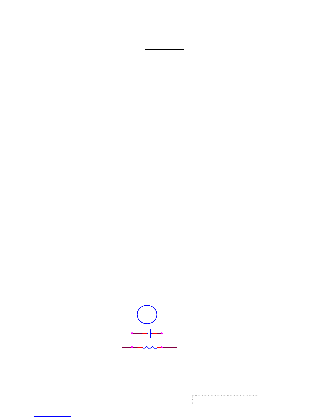
. LEAKAGE CURRENT HOT CHECK
3-1 Plug the AC cord directly into the AC outlet. Do not use an isolation transformer during this check.
3-2 Connect a 1500 ohm , 10 watt resistor , paralleled by a 0.15uF capacitor between each metallic part and a good
earth ground.
3-3 Use an AC voltmeter with 1000 ohm / volt or more
combination 1500 ohm resistor and 0.15uF capacitor.
3-4 Move the resistor connection to each exposed metallic part and measure the voltage.
3
-5 Reverse the polarity of the AC plug in the AC outlet and repeat the above measurement.
3-6 Voltage measured must not exceed 1.5 volt RMS, from any exposed metallic part to the ground. A leakage
current tester may be used in the above hot check, in which case any circuit measured must not exceed 1.0
milliamp. In the case of a measurement exceeding the 1.0 milliamp value, a rework is required to eliminate the
chance of a shock hazard .
AC VOLTMETER
sensitivity and measure the AC voltage across the
V
ViewSonic Corporation Confidential
To Metal Parts
0.15u
.
1500 10W
1
Earth Ground
-
Do Not Copy VE710b/s-1

2. Specification
Mechanical :
Dimension ( W x H x D ) mm
Set : a. with stand: 377.6 x 374 x 195.6 mm
b. Without stand: 377.6 x 311.8 x 56.9 mm
Slim bezel: 19.0 / 19.0 / 19.0/21.0
Base (L X W): 195.6 x 201 mm
Packing : ( W x H x D ) mm: 450 x 522 x 135 mm
Weight : Net / Gross ( Kg ): 4.1 / 5.2
Wall Mount (VESA): 100 x 100 mm
LCD Panel type: CPT / CLAA170EA03
Max. resolution (HxV): 1280 x 1024
Nominal picture size (HxV): 338 mm x 270 mm
Display colors: 16.2 M ( 6 bit + dithering )
Dot pitch: 0.264 mm
Response time: 9 +16 / 25ms (Tr + Tf / typical)
Brightness (100% white): Typical : 300 cd/m² , Min. 240 cd/m²
Contrast: Typical : 450:1, Min. 360:1
Viewing angle: 70 / 70 /65 / 65 (L/R/T/B CR>=10)
Synchronization: Fh = 30~80 KHz / Fv=50~85Hz
Presets: 18 timing modes
OSD Language: 9 languages
Color Temperatures RGB: 6500°K (default) / 9300°K 5400°K / User R,G,B
Plug & Play: DDC1/2B interface
Scaler chip: Mstar MST8116a
AC Power range: 90 V ~ 264 V, 50 Hz / 60 Hz
Power consumption: < 45W green / < 1W amber
(On / Off mode)
2
ViewSonic Corporation Confidential
-
Do Not Copy VE710b/s-1
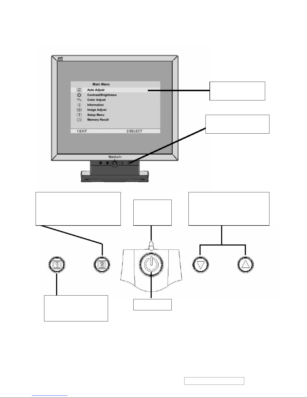
3. Front Panel Function Control Description
Main Menu
With OSD controls
Front Control Panel
shown below in detail
Power On / Off
Displays the Main Menu or
exits the control screen
and saves adjustments.
Displays the control screen for the
highlighted control. Also toggles
between two controls on some screens.
Also a shortcut to auto image adjust
Power light
Green = ON
Orange =
Power Saving
Scrolls through menu options and
adjusts the displayed control.
Also a shortcut to display the
Contrast adjustment control screen.
3
ViewSonic Corporation Confidential
-
Do Not Copy VE710b/s-1

Main Menu Controls
Adjust the menu items shown below by using the up and down buttons.
A. Auto Image Adjust automatically sizes, centers, and fine tunes the video signal to eliminate waviness and
distortion. Press the [2] button to obtain a sharper image.
NOTE: Auto Image Adjust works with most common video cards. If this function does not work on your
LCD display, then lower the video refresh rate to 60 Hz and set the resolution to its pre-set value.
B. Contrast adjusts the difference between the image background (black level) and the foreground (white
level).
C. Brightness adjusts the lamps current to control the screen brightness.
D. Color Adjust
provides several color options: preset color temperatures and Custom User Color which allows
you to adjust red (R), green (G), and blue (B). The factory setting for this product is 6500K (6500° Kelvin).
9300K — Adds blue to the screen image for cooler white (used in most office settings with fluorescent
lighting).
5400K — Adds red to the screen image for warmer white and richer red.
Custom User Color — Individual adjustments for red, green, and blue.
1 To select color (R, G or B) press button [2].
2 To adjust selected color, press or .
3 When you are finished making all color adjustments, press button [1] twice.
E. Information displays the timing mode (video signal input) coming from the graphics card in your computer.
See your graphic card’s user guide for instructions on changing the resolution and refresh rate (vertical
frequency). VESA 1280 x 1024 @ 60 Hz (recommended) means that the resolution is 1280 x 1024 and the
refresh rate is 60 Hertz.
F. Manual Image Adjust
controls are explained below:
H. Size (Horizontal Size) adjusts the width of the screen image.
NOTE: Vertical size is automatic with your LCD display.
H./V. Position adjusts horizontal and vertical position of the screen image. You can toggle between
Horizontal and Vertical by pressing button [2]. Horizontal move s the screen image to the left or to the right.
Vertical moves the screen image up and down.
Fine Tune sharpens focus by aligning the illuminated text and/or graphic characters.
Sharpness adjusts the clarity and focus of the screen image.
Setup Menu controls are explained below:
Language allows you to choose the language used in the menus and control screens.
Resolution Notice displays the recommended resolution for this LCD display.
Enable allows the Resolution Notice to appear on-screen.
Disable will not allow the Resolution Notice to appear on-screen.
OSD Timeout sets the length of time an on-screen display screen is displayed. For example, with a“15
second” setting, if a control is not pushed within 15 seconds, the display OSD
disappears.
G. OSD Position allows you to move the on-screen display menus and control screens.
H. Memory Recall
returns adjustments to the original factory settings if the display is operating in a factory
Preset Timing Mode listed in this user guide.
4
ViewSonic Corporation Confidential
-
Do Not Copy VE710b/s-1
4-1. Outline
POWER On/Off , LED, Button"2" , Up arrow- button , Down arrow button , Button"1" , button , Down arrow
button , Button"1" , on the front panel.
Video signal connector, audio line-in receptacle and AC-IN are located on the back side of the cabinet.
l OSD menu includes the following function;
AUTO IMAGE ADJUST
CONTRAST / BRIGHTNESS
COLOR ADJUST
INFORMATION
MANUAL IMAGE ADJUST
SETUP MENU
MEMORY RECALL
l CONTRAST and BRIGHTNESS can be directly controlled with UP / DN key.
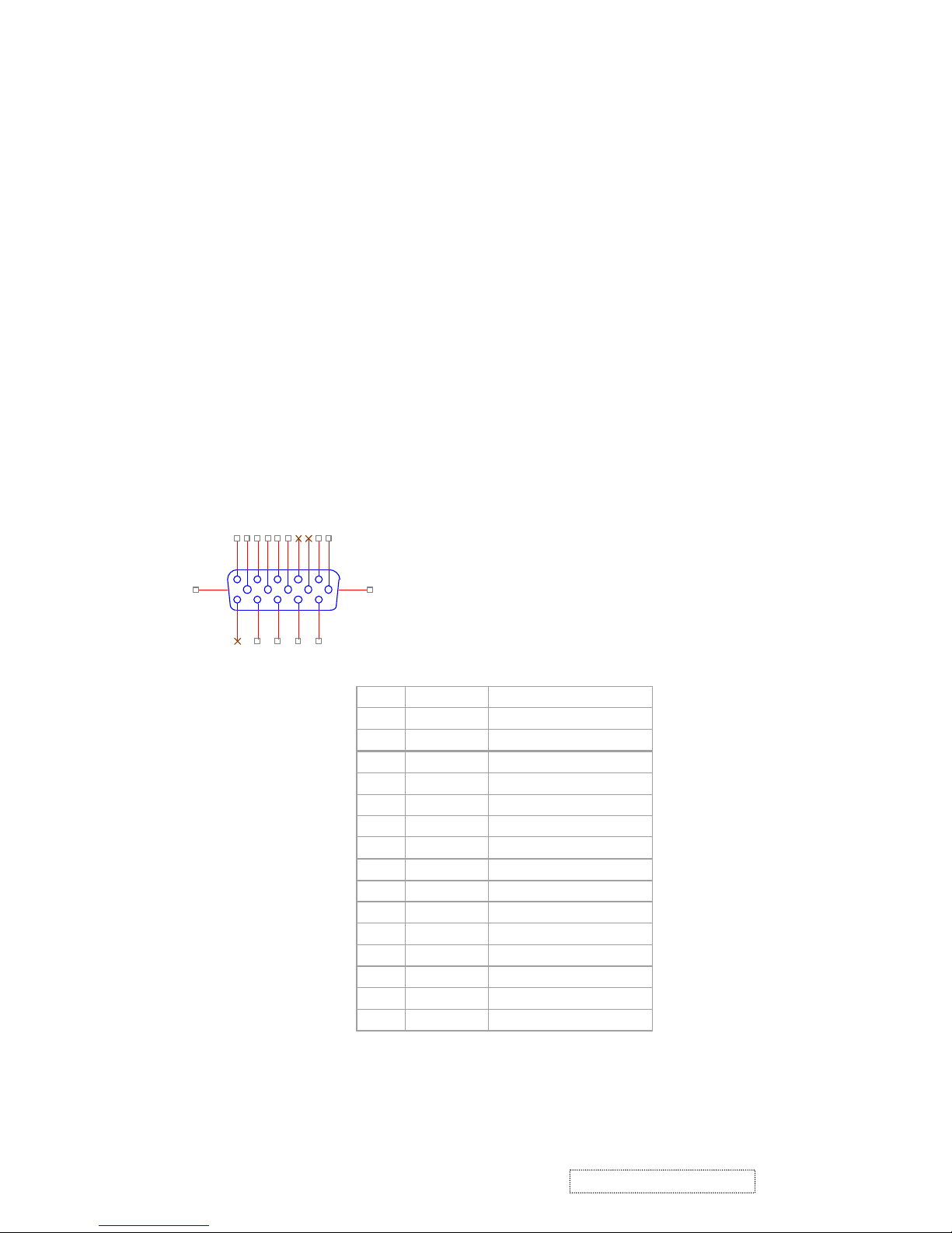
4-2. CONNECTORS
l AC inlet : CEE22 typed connector
l Video signal connector 15P Mini D-Sub
PIN
MNEMONI
SIGNAL
1RVRed Video
2GVGreen Video
3BVBlue Video
4NCNone5GND
Ground(DDC return)
6RGRed GND
7GGGreen GND
8BGBlue GND
9
+5V
+ 5V (for DDC)
10SGSync GND
11NCNone
12
SDA
DDC Data
13HSHorizontal Sync
14VSVertical Sync
15
SCL
DDC Clock
CN6
DB15HD
162738495
1112131415
10
16 17
4. Circuit Description
5
ViewSonic Corporation Confidential
-
Do Not Copy VE710b/s-1
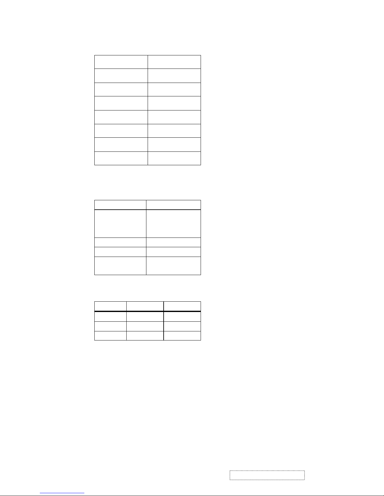
4-3. ELECTRICAL SPECIFICATIONS
l Standard conditions
Display Area 338 x 270 mm
Video Signal 0.7 Vpp
Contrast Max.
Brightness Max.
Ambient
20 +/- 5 °C
Input AC
Warming up > 30 min
Display 1280 x 1024
l
POWER
- Power supply
Input Voltage 90 -240 ~Volts
Power Frequency
Input current
50/ 60 Hz +/-3Hz
<1.5Arms @ 90Vac
<0.75Arms@265Vac
Inrush current 90A(max.) at 230Vac
Power consumption 50Watt
Output Voltage @0-4.8A load 12Vdc
+/-5%
- Power Management
State Power Indicator
On 45Watt Green
Standby <1Watt Amber
Off <1Watt
l Acceptable timing
If your timing is within following specification, this LCD display can automatically function with a certain
position.
Horizontal: Sync frequency : 30~80 kHz
Vertical: Sync frequency : 50~85Hz
l Signal level and input impedance
- Video Signal level This LCD display is adjusted at the factory using 0,7 Vp-p Video signal.
- Sync Signal level
H/V Separate : TTL level
- Input impedance
Video input : 75 ohms
Sync input : > 1 k ohms
6
ViewSonic Corporation Confidential
-
Do Not Copy VE710b/s-1

4-4. SIGNAL CABLE : Non-detachable cable with Mini D-Sub 15P connector at one end. Length : 1.8 meter.
4-5. EDID data
Analog EDID
Time: 09:08:54
Date: Wed Sep 04, 2002
______________________________________________________________________
______________________________________________________________________
VIEWSONIC CORPORATION
EDID Version # 1, Revision # 3
DDCTest For: VSC VE710s
______________________________________________________________________
______________________________________________________________________
0 | 00 FF FF FF FF FF FF 00 5A 63
10 | 18 F5 01 01 01 01 01 0D 01 03
20 | 08 22 1B 78 2E 04 A5 A3 58 4F
30 | 95 24 19 50 54 BF EF 80 81 80
40 | 81 40 71 4F 01 01 01 01 01 01
50 | 01 01 01 01 30 2A 00 98 51 00
60 | 2A 40 30 70 13 00 52 0E 11 00
70 | 00 1E 00 00 00 FF 00 41 33 33
80 | 30 33 30 31 30 30 30 30 31 0A
90 | 00 00 00 FD 00 32 4B 1E 50 0E
100 | 00 0A 20 20 20 20 20 20 00 00
110 | 00 FC 00 56 45 37 31 30 73 0A
120 | 20 20 20 20 20 20 00 98
____________________________________________________________________
(08-09) ID Manufacturer Name = VSC
(10-11) Product ID Code (Non-Alphanumerical) =
F518
(12-15) Last 5 Digits of Serial Number = NOT SPECIFIED
(16) Week of Manufacture = 01
(17) Year of Manufacture = 2003
(10-17) Complete Serial Number = NOT SPECIFIED
(18) EDID Structure Version Number = 1
(19) EDID Structure Revision Number = 3
(20) VIDEO INPUT DEFINITION : =
Separate Sync, Analog signal, 0.700V/0.300V (1.000 Vp-p)
(21) Maximum Horizontal Image Size = 340mm
(22) Maximum Vertical Image Size = 270mm
(23) Display Gamma = 2.20
(24) DPMS Supported Feature: = Active Off.
Display type = RGB color display
7
ViewSonic Corporation Confidential
-
Do Not Copy VE710b/s-1
(25-34) CHROMA INFO:
Red x = 0.633 Green x = 0.300 Blue x = 0.146 White x = 0.313
Red y = 0.336 Green y = 0.586 Blue y = 0.103 White y = 0.329

(35) ESTABLISHED TIMING I:
720 x 400 @ 70Hz (VGA, IBM)
640 x 480 @ 60Hz (MAC II, Apple)
640 x 480 @ 67Hz (VESA)
640 x 480 @ 72Hz (VESA)
640 x 480 @ 75Hz (VESA)
800 x 600 @ 56Hz (VESA)
800 x 600 @ 60Hz (VESA)
(36) ESTABLISHED TIMING II:
800 x 600 @ 72Hz (VESA)
800 x 600 @ 75Hz (VESA)
832 x 624 @ 75Hz (MAC II, Apple)
1024 x 768 @ 60Hz (VESA)
1024 x 768 @ 70Hz (VESA)
1024 x 768 @ 75Hz (VESA)
1280 x 1024 @ 75Hz (VESA)
(37) Manufacturer's Reserved Timing:
1152 x 870 @ 75Hz (MAC II, Apple)
(38-53) Standard Timing Identification:
#1: 1280 x 1024 @60Hz
#2: 1280 X 960 @60HZ
#3: 1152 X 864 @75HZ
#4: (44) not specified
#5: (46) not specified
#6: (48) not specified
#7: (50) not specified
#8: (52) not specified
(54-71) Detail Timing Description #1: 1280x1024 Pixel Clock=108.0MHz
Horizontal Image Size=338mm Vertical Image Size=270mm
Refresh Mode: Non-Interlaced Normal display, no stereo
HORIZONTAL:
Active Time = 1280 pixels Blanking Time = 408 pixels
Sync Offset = 48 pixels Sync Pulse Width = 112 pixels
Border = 1 pixels Frequency = 64.0 kHz
8
ViewSonic Corporation Confidential
-
Do Not Copy VE710b/s-1
VERTICAL:
Active Time = 1024 lines Blanking Time = 42 lines
Sync Offset = 1 lines Sync Pulse Width = 3 lines
Border = 0 lines Frequency = 60.0 Hz
Sync configuration: Digital separate, V(+), H(+)

(72-89) Monitor Description:
Monitor S/N: A33030100001
(90-107) Monitor Description:
Monitor Range Limits:
Vertical Frequency (min) = 50Hz
Vertical Frequency (max) = 75Hz
Horizontal Frequency (min) = 30Hz
Horizontal Frequency (max) = 82Hz
Maximum Supported Pixel Clock = 140MHz
SECONDARY GTF - NOT SUPPORTED
(108-125) Monitor Description:
Monitor Name: VE710s
(127) Checksum OK
9
ViewSonic Corporation Confidential
-
Do Not Copy VE710b/s-1
Time: 14:35:05
Date: Thu Jul 03, 2003
VIEWSONIC CORPORATION
EDID Version # 1, Revision # 3
DDCTest For: ViewSonic VE710b
128 BYTES OF EDID CODE:
0 1 2 3 4 5 6 7 8 9
0 | 00 FF FF FF FF FF FF 00 5A 63
10 | 18 F6 01 01 01 01 01 0D 01 03
20 | 08 22 1B 78 2E 04 A5 A3 58 4F
30 | 95 24 19 50 54 BF EF 80 81 80
40 | 81 40 71 4F 01 01 01 01 01 01
50 | 01 01 01 01 30 2A 00 98 51 00
60 | 2A 40 30 70 13 00 52 0E 11 00
70 | 00 1E 00 00 00 FF 00 41 33 34
80 | 30 33 30 31 30 30 30 30 31 0A
90 | 00 00 00 FD 00 32 4B 1E 50 0E
100 | 00 0A 20 20 20 20 20 20 00 00
110 | 00 FC 00 56 45 37 31 30 62 0A
120 | 20 20 20 20 20 20 00 A7
_____________________________________________________________
______________________________________________________________________
______________________________________________________________________
______________________________________________________________________
______________________________________________________________________

(08-09) ID Manufacturer Name = VSC
(11-10) Product ID Code = F618
(12-15) Last 5 Digits of Serial Number = Not Used
(16) Week of Manufacture = 01
(17) Year of Manufacture = 2003
(10-17) Complete Serial Number = See Descriptor Block
(18) EDID Version Number = 1
(19) EDID Revision Number = 3
(20) VIDEO INPUT DEFINITION:
Separate Syncs, Analog singal, 0.700V/0.300V(1.000 Vp-p)
(21) Maximum Horizontal Image Size = 340 mm
(22) Maximum Vertical Image Size = 270 mm
(23) Display Gamma = 2.20
(25-34) CHROMA INFO:
Red X - 0.637 Green X - 0.310 Blue X - 0.143 White X - 0.313
Red Y - 0.344 Green Y - 0.582 Blue Y - 0.100 White Y - 0.329
(35) ESTABLISHED TIMING I:
720 X 400 @ 70Hz (IBM,VGA)
640 X 480 @ 60Hz (IBM,VGA)
640 X 480 @ 67Hz (Apple,Mac II)
640 X 480 @ 72Hz (VESA)
640 X 480 @ 75Hz (VESA)
800 X 600 @ 56Hz (VESA)
800 X 600 @ 60Hz (VESA)
(36) ESTABLISHED TIMING II:
800 X 600 @ 72Hz (VESA)
800 X 600 @ 75Hz (VESA)
832 X 624 @ 75Hz (Apple,Mac II)
1024 X 768 @ 60Hz (VESA)
1024 X 768 @ 70Hz (VESA)
1024 X 768 @ 75Hz (VESA)
1280 X 1024 @ 75Hz (VESA)
(37) Manufacturer's Reserved Timing:
1152 X 870 @ 75Hz (Apple,Mac II)
(24) Power Management and Supported Feature(s):
Active Off/Very Low Power, Standard Default Color Space,
Preferred Timing Mode
Display Type = R/G/B Color
10
ViewSonic Corporation Confidential
-
Do Not Copy VE710b/s-1

(38-53) Standard Timing Identification:
1280 X 1024 @60Hz
1280 X 960 @60Hz
1152 X 864 @75Hz
Not Used
Not Used
Not Used
Not Used
Not Used
(54-71) Detailed Timing / Descriptor Block 1:
1280x1024 Pixel Clock: 108.00 MHz
Horizontal Image Size: 338 mm Vertical Image Size: 270 mm
Refreshed Mode: Non-Interlaced Normal Display - No Stereo
Horizontal:
Active Time: 1280 pixels Blanking Time: 408 pixels
Sync Offset: 48 pixels Sync Pulse Width: 112 pixels
Border: 0 pixels Frequency: 63.98 KHz
Vertical:
Active Time: 1024 lines Blanking Time: 42 lines
Sync Offset: 1 lines Sync Pulse Width: 3 lines
Border: 0 lines Frequency: 60.02 Hz
Digital Separate, Horizontal Polarity (+) Vertical Polarity (+)
(72-89) Detailed Timing / Descriptor Block 2:
Monitor Serial Number:
A34030100001
(90-107) Detailed Timing / Descriptor Block 3:
Monitor Range Limits:
Min Vertical Freq - 50 Hz
Max Vertical Freq - 75 Hz
Min Horiz. Freq - 30 KHz
Max Horiz. Freq - 80 KHz
Pixel Clock - 140 MHz
Secondary GTF - Not Supported
(108-125) Detailed Timing / Descriptor Block 4:
Monitor Name :
VE710b
(126) No Extension EDID Block(s)
(127) CheckSum OK
11
ViewSonic Corporation Confidential
-
Do Not Copy VE710b/s-1
4-6. THEORY OF OPERATION
This section describes the function of the LCD monitor per functional block.
This monitor includes MB board, inverter board, adapter and button board.
MB Board
The MB board is a four-layer, single-landed design with ground and internal planes provided. DC power from the
power adapter enter the board through DC jack. Other connectors on the board are for inverter, audio and button
board .The VGA cable is a signal cable that contains video signal, sync signal and DDC signal from PC VGA
adapter. This system board consists of 4 functional areas : flat panel controller, flash ROM , power regulator and
Audio amplifier
Flat panel controller… MST8116A (U3)
The heart of the system board is mstar MST8116A. The MST8116A is a graphics processing IC for LCD
monitor. It provides all key IC functions required for LCD panel. On-chip functions include a high-speed
triple-ADC , PLL, high scaling engine, OSD controller and on -chip micro controller.
a) Clock Generation :
Crystal Input Clock (TCLK and XTAL). This is the input pair to an internal crystal oscillator and
corresponding logic. A 14.318 MHz crystal is recommended.
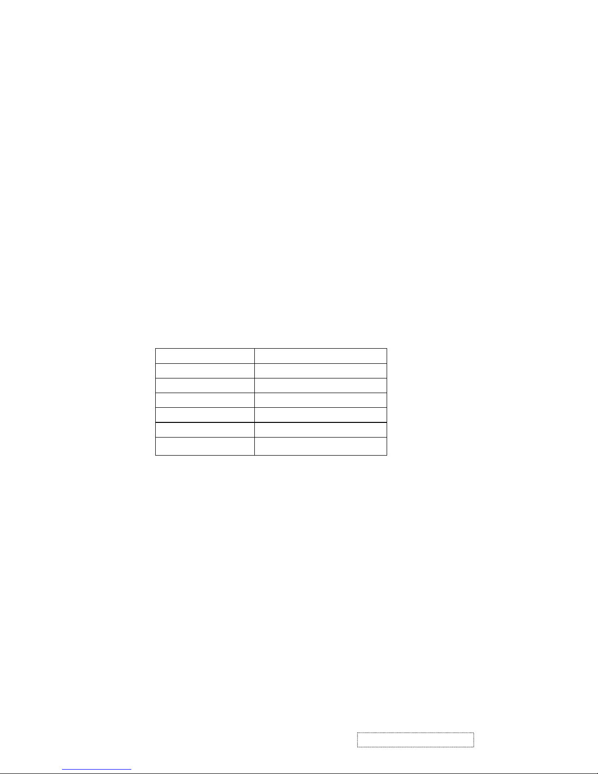
b) Analog to Digital Converter:
The MST8116A chip has three ADC's (analog-to-digital converters), one for each color (red, green and
blue) .The analog RGB signals are connected to
MST8116A as described
below
Pin Name Pin Number
Red + 63
Red - 62
Green + 60
Green - 59
Blue + 58
Blue - 57
c) OSD : The MST8116A has a fully programmable ,high-quality OSD controller. The on-chip static
RAM(4096 words by 24 bits) stores the cell map and the cell definitions.
d) MTV312 Micro controller: The MTV312 micro controller(MCU) serves as the system micro controller. It
programs the MST8116A and manages other devices in the system such as the keypad, the backlight, LED,
audio and non-volatile RAM. using general purpose input/output (GPIO) pins.
l
l
12
ViewSonic Corporation Confidential
-
Do Not Copy VE710b/s-1
 Loading...