

Page 1

Service Manual
ViewSonic VA521
VE510b/s-21
Model No. VLCDS27996-1W
Model No. VLCDS27996-2W/-3W
15” Color TFT LCD Display
ViewSonic
(VA521/VE510b/s-2_SM_819 Rev. 1b Apr. 2004)
381 Brea Canyon Road, Walnut, California 91789 USA - (800) 888-8583
Page 2
Copyright
Copyright
reproduced, transmitted, transcribed, stored in a retrieval system, or translated into any language or
computer language, in any form or by any means, electronic, mechanical, magnetic, optical, chemical,
manual or otherwise, without the prior written permission of ViewSonic Corporation.
Disclaimer
ViewSonic makes no representations or warranties, either expressed or implied, with respect to the
contents hereof and specifically disclaims any warranty of merchantability or fitness for any particular
purpose. Further, ViewSonic reserves the right to revise this publication and to make changes from time
to time in the contents hereof without obligation of ViewSonic to notify any person of such revision or
changes.
Trademarks
Optiquest is a registered trademark of ViewSonic Corporation.
ViewSonic is a registered trademark of ViewSonic Corporation.
All other trademarks used within this document are the property of their respective owners.
2004 by ViewSonic Corporation. All rights reserved. No part of this publication may be
¤
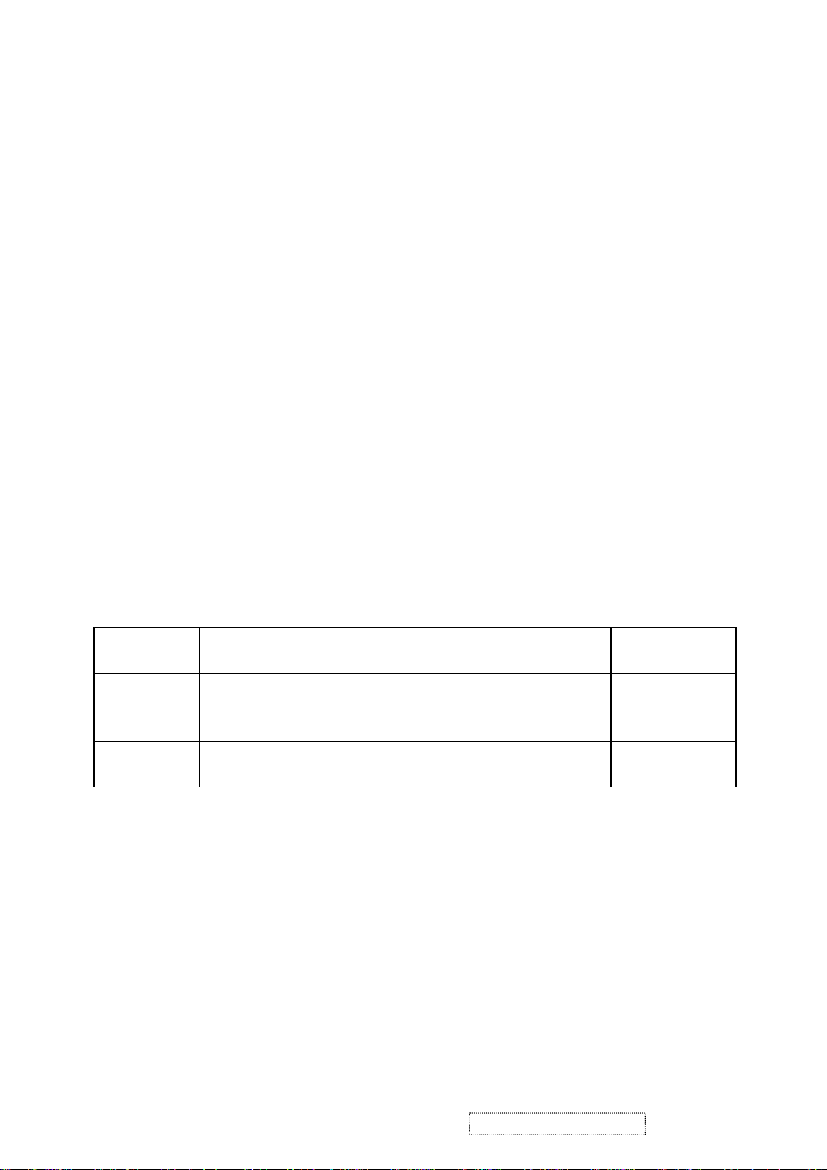
Revision History
Revision Date Description Of Changes Approval
1a 02/11/04 Initial Release DCN-4207 Angela Lu
1b 04
/05/04 Add VE510b/s-2 DCN-4280 Angela Lu
ViewSonic Corporation Confidential
i
-
Do Not Copy VA521
VE510b/s-2
Page 3

TABLE OF CONTENTS
1. Precautions and Safety Notices
2. Specification
3. Front Panel Function Control Description
4. Circuit Description
5. Adjusting Procedure
6. Trouble Shooting Flow Chart
7. Recommended Spare Parts List
8. Exploded Diagram And Spare Parts List
9. Block Diagram
10. Schematic Diagrams
11. PCB Layout Diagrams
1
2
5
10
12
13
15
28
36
37
44
ViewSonic Corporation Confidential
ii
-
Do Not Copy VA521
VE510b/s-2
Page 4

1. Precautions and Safety Notices
1.1 SAFETY PRECAUTIONS
This monitor is manufactured and tested on a ground principle that a user's safety comes first. However, improper
use or installation may cause damage to the monitor as well as to the user. Carefully go over the following
WARNINGS before installing and keep this guide handy.
WARNINGS
.
This monitor should be operated only at the correct power sources indicated on the label on the rear end of the monitor.
If you're unsure of the power supply in your residence, consult your local dealer or power company.
.
Do not try to repair the monitor your self as it contains no user-serviceable parts. This monitor should only be
repaired by a qualified technician.
.
Do not remove the monitor cabinet. There are high-voltage parts inside that may cause electric shock to human
bodies, even when the power cord is unplugged.
.
Stop using the monitor if the cabinet is damaged. Have it checked by a service technician.
.
Put your monitor only in a clean, dry environment. If it gets wet, unplug the power cable immediately and
consult your service technician.
.
Always unplug the monitor before cleaning it. Clean the cabinet with a soft, dry cloth. Apply non-ammonia
based cleaner onto the cloth, not directly onto the glass screen.
.
Keep the monitor away from magnetic objects, motors, TV sets, and transformer.
.
Do not place heavy objects on the monitor or power cord.
1.2 PRODUCT SAFETY NOTICE
Many electrical and mechanical parts in this chassis have special safety visual inspections and the protection
afforded by them cannot necessarily be obtained by using replacement components rated for higher voltages,
wattage, etc. Before replacing any of these components read the parts list in this manual carefully. The use of
substitute replacement parts which do not have the same safety characteristics as specified in the parts list may
create shock, fire, or other hazards.
1.3 SERVICE NOTES
.
When replacing parts or circuit boards, clamp the lead wires around terminals before soldering.
.
When replacing a high wattage resistor (more than 1W of metal oxide film resistor) in circuit board, keep the
resistor about 5mm away from circuit board.
.
Keep wires away from high voltage, high temperature components and sharp edges.
.
Keep wires in their original position so as to reduce interference.
.
For usage of this product please also refer to the user's manual.
ViewSonic Corporation Confidential
1
-
Do Not Copy VA521
VE510b/s-2
Page 5

2. Specification
2.1 PRODUCT SPECIFICATION
LCD Panel 15.0" TFT
Power Management Energy Star compliant VESA
DPMS compatible
< 1W
Displayable Resolution XGA 1024× 768 (max.)
Pixel Dimension 0.297× 0.297mm
LCD Display Color 16.7M Color Max. (8bit)
Viewing Angle CR
Horizontal: -60°~+60°
Vertical: -55°~+45°
Tilt Up 0°~ 5°
Down (setp1) 0°~ 22.5°
(setp2) 22.5°~ 90°
≧10
Contrast Ratio 300: 1 (min.)
400 : 1 (typ.)
Brightness 200 cd/m
250 cd/m2 (typ.)
2
(min.)
Response Time Tr: 9 ms Tf: 16ms (typ.)
Active Display Area 304.1mm× 228.1mm
Temperature Operating: 0°C ~ +40°C
Storage: -20°C ~ +60°C
Power Input Voltage: 100~240 Vac
Consumption: 30 Watts (Max.)
ViewSonic Corporation Confidential
2
-
Do Not Copy VA521
VE510b/s-2
Page 6
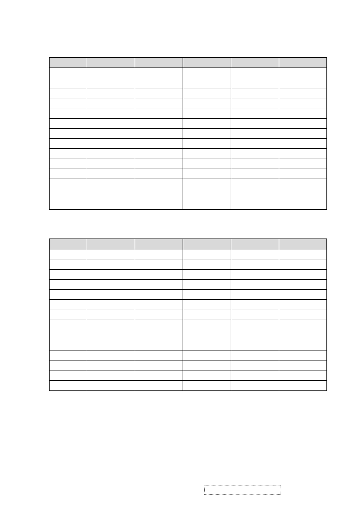
2.2 SUPPORTING TIMING CHART
ITEM 1 2 3 4 5
TIMING 640×350@70Hz 640×480@60Hz 640×480@67Hz 640×480@75Hz 640×480@72Hz
Pixel Rate 25.175MHz 25.175MHz 30.240MHz 31.500MHz 31.500MHz
H TOTAL 31.778us 31.778us 28.571us 26.667us 26.413us
H DISPLAY
25.422us 25.422us 21.164us 20.317us 20.317us
H B-Porch 1.907us 1.907us 3.175us 3.810us 4.063us
H Width 3.813us 3.813us 2.116us 2.032us 0.270us
H Border 0.318us 0.318us 0.000us 0.000us 0.000us
V TOTAL 14.268ms 16.683ms 15.000ms 13.334ms 13.734ms
V DISPLAY
11.122ms 15.253ms 13.714ms 12.800ms 12.678ms
V B-Porch 1.907ms 1.049ms 1.114ms 0.427ms 0.528ms
Vs Width 0.064ms 0.064ms 0.086ms 0.080ms 0.079ms
V Border 0.191ms 0.254ms 0.000ms 0.000ms 0.000ms
H/V Sync +/- -/- -/- -/- -/Interlace No. No. No. No. No.
ITEM 6 7 8 9 10
TIMING 640×480@85Hz 720×400@70Hz 800×600@56Hz 800×600@60Hz 800×600@72Hz
Pixel Rate 36.000MHz 28.322MHz 36.000MHz 40.000MHz 50.000MHz
H TOTAL 22.111us 31.778us 28.444us 26.400us 20.800us
H DISPLAY
17.778us 25.422us 22.222us 20.000us 16.000us
H B-Porch 2.222us 1.907us 3.556us 2.200us 1.280us
H Width 1.556us 3.813us 2.000us 3.200us 2.400us
H Border 0.000us 0.318us 0.000us 0.000us 0.000us
V TOTAL 11.764ms 14.268ms 17.778ms 16.579ms 13.853ms
V DISPLAY
11.093ms 12.711ms 17.066ms 15.840ms 12.480ms
V B-Porch 0.578ms 1.112ms 0.626ms 0.607ms 0.478ms
Vs Width 0.069ms 0.064ms 0.057ms 0.106ms 0.125ms
V Border 0.000ms 0.222ms 0.000ms 0.000ms 0.000ms
H/V Sync -/- -/+ +/+ +/+ +/+
Interlace No. No. No. No. No.
ViewSonic Corporation Confidential
3
-
Do Not Copy VA521
VE510b/s-2
Page 7
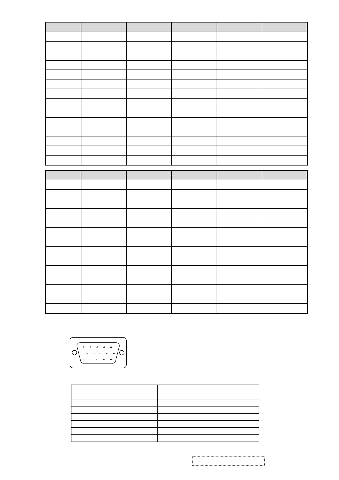
ITEM 11 12 13 14 15
TIMING 800×600@75Hz 800×600@85Hz 832×624@75Hz
Pixel Rate 48.500MHz 56.250MHz 57.280MHz 65.000MHz 75.000MHz
H TOTAL 21.333us 18.631us 20.112us 20.677us 17.707us
H DISPLAY
16.162us 14.222us 14.525us 15.754us 13.653us
H B-Porch 3.232us 2.702us 3.771us 2.462us 1.920us
H Width 1.616us 1.138us 1.118us 2.092us 1.813us
H Border 0.000us 0.000us 0.000us 0.000us 0.000us
V TOTAL 13.333ms 11.756ms 13.417ms 16.666ms 14.272ms
V DISPLAY
12.800ms 11.179ms 12.552ms 15.880ms 13.599ms
V B-Porch 0.448ms 0.503ms 0.784ms 0.600ms 0.513ms
Vs Width 0.064ms 0.056ms 0.060ms 0.124ms 0.106ms
V Border 0.000ms 0.000ms 0.00ms 0.000ms 0.000ms
H/V Sync +/+ +/+ -/- -/- -/Interlace No. No. No. No. No.
ITEM 16 17
TIMING 1024×768@72Hz 1024×768@75Hz
Pixel Rate 77.066MHz 78.750MHz
H TOTAL 17.232us 16.660us
H DISPLAY
H B-Porch 1.869us 2.235us
13.287us 13.003us
H Width 1.765us 1.219us
H Border 0.000us 0.000us
V TOTAL 13.889ms 13.328ms
V DISPLAY
13.234ms 12.795ms
V B-Porch 0.500ms 0.466ms
Vs Width 0.103ms 0.050ms
V Border 0.000ms 0.000ms
H/V Sync -/- +/+
Interlace No. No.
2.3 D-SUB CONNECTOR
D-SUB 15 PIN CONNECTOR
1 2 3 4 5
6 7 8 9 10
11 12 13 14 15
SIGNAL LEVEL
CONNECTOR
R RED 0.7vp-p(VIDEO)
G GREEN 0.7vp-p(VIDEO)
B BLUE 0.7vp-p(VIDEO)
H H/SYNC TTL positive or negative
V V/SYNC TTL positive or negative
SDA DDC1/2B TTL
SCL DDC1/2B TTL
1024×768@60Hz
1.Red Video 6.Red GND 11.NC
2.Green Video 7.Green GND 12.SDA
3.Blue Video 8.Blue GND 13.H-sync
4.NC 9. +5V for DDC 14.V-sync
5.GND 10.GND 15.SCL
SIGNAL DESCRIPTION
1024×768@70Hz
ViewSonic Corporation Confidential
4
-
Do Not Copy VA521
VE510b/s-2
Page 8
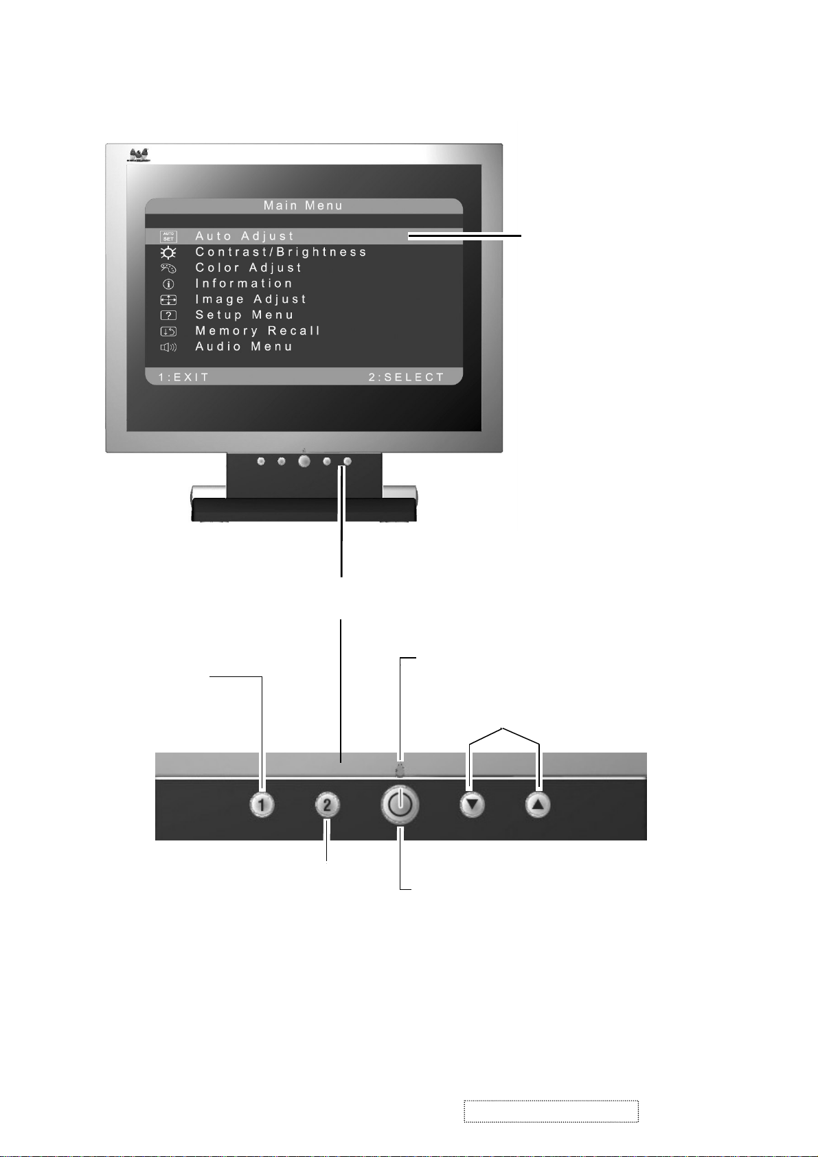
3. Front Panel Function Control Description
Main Menu
with OnView controls
Displays, saves
changes to, and exits
the Main Menu.
Selects a highlighted control. Also,
displays the control screen for the
selected control and toggles
between control pairs.
Front Control Panel
Power light
Scroll through menu
options and adjust the
displayed control.
Power On/Off
ViewSonic Corporation Confidential
5
-
Do Not Copy VA521
VE510b/s-2
Page 9
Do the following to adjust the screen image:
.
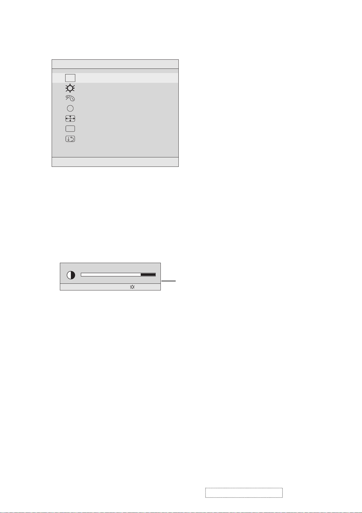
To display the Main Menu, press button [1].
Main Menu
AUTO
SET
?
1:EXIT 2:SELECT
Auto Adjust
Contrast/Brightness
Color Adjust
Information
i
Image Adjust
Setup Menu
Memory Recall
NOTE: All OnView menus and adjustment screens disappear automatically
after about 15 seconds. This time period is adjustable through the Setup
menu and the OSD timeout control described on page 11.
.
To highlight a control you want to adjust, press I or J to scroll up or down
the Main Menu.
.
To select the highlighted control, press button [2]. A control screen appears
like the example shown below.
Contrast
1:EXIT 2: Brightness
.
To adjust the control, press the up I or down J buttons.
.
To save the adjustments and exit the menu, press button [1] twice.
The line at the
bottom of the
screen tells you
what you can do
next: Exit or Select
the control that is
highlighted.
The following tips may help you optimize your display:
Adjust your computer's graphic card so that it outputs a video signal 1024 x
•
768 @ 60 Hz to the LCD display. (Look for instructions on“changing the
refresh rate” in your graphic card's user guide.)
•If necessary, make small adjustments using H. POSITION and V. POSITION
until the screen image is completely visible
edge of the screen should barely touch the illuminated “active area” of the
LCD display.)
ViewSonic Corporation Confidential
. (The black border around the
6
-
Do Not Copy VA521
VE510b/s-2
Page 10
Main Menu Controls
Adjust the menu items shown below by using the up Iand down Jbuttons.
Contro Explanation
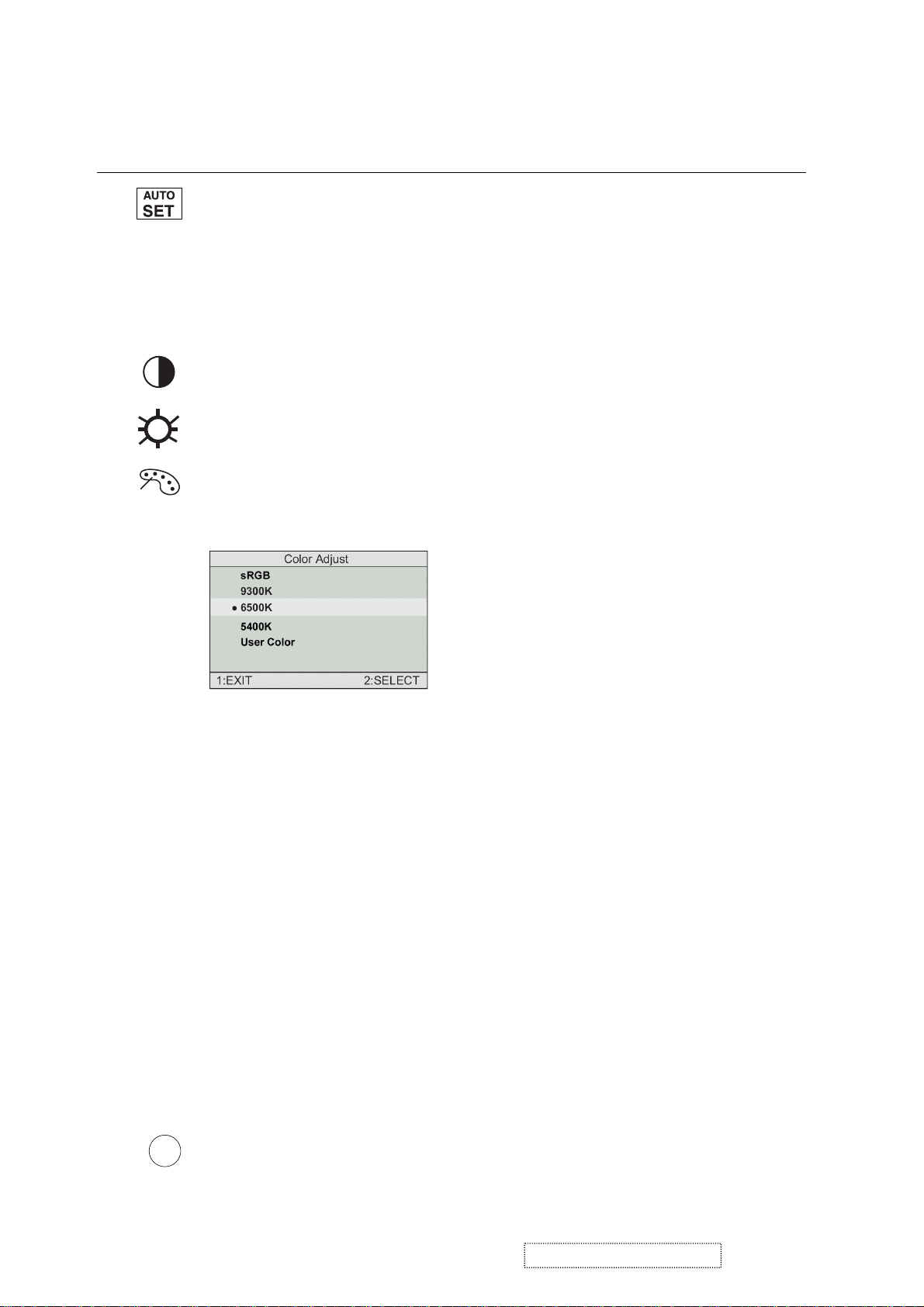
Auto Adjust
automatically sizes, centers, and fine tunes the
videosignal to eliminate waviness and distortion.
Press the [2] button to obtain a sharper image.
NOTE
: Auto Adjust works with most common video cards. If
this function does not work on your LCD display, then lower the
video refresh rate to 60 Hz and set the resolution to its pre-set
value.
Contrast
adjusts the difference between the image background
(black level) and the foreground (white level).
Brightness
Color Adjust
adjusts background black level of the screen image.
provides several color options: preset color
temperatures and User which allows you to adjust red (R), green
(G), and blue (B). The factory setting for this product is 6500K
(6500 Kelvin).
sRGB
— sRGB is quickly becoming the industry standard for
color management, with support being included in many of the
latest applications. Enabling this setting allows the LCD display
to more accurately display colors the way they were originally
intended. Enabling the sRGB setting will cause the Contrast and
Brightness adjustments to be disabled.
9300K
— Adds blue to the screen image for cooler white (used
in most office settings with fluorescent lighting).
6500K
— Adds red to the screen image for warmer white and
richer red.
5400K
User Color
and blue (B)
1
2
Important
— Adds green to the screen image for a darker color.
— Individual adjustments for red (R), green (G),
.
To select color (R, G or B) press button [2].
To adjust selected color, press ▲ or ▼.
: If you select RECALL from the Main Menu when
the product is set to a Preset Timing Mode, colors return to the
6500K factory preset.
Information
i
coming from the graphics card in your computer. See your
graphic card’s user guide for instructions on changing the
resolution and refresh rate (vertical frequency).
displays the timing mode (video signal input)
ViewSonic Corporation Confidential
7
-
Do Not Copy VA521
VE510b/s-2
Page 11
VESA 1024 x 768 @ 60 Hz (recommended) means that the
resolution is 1024 x 768 and the refresh rate is 60 Hertz.
Information
H. Frequency: 48.60 KHz
V. Frequency: 60.00 Hz
Pixel Clock: 65.00 MHz
Resolution: 1024 x 768
Model Number: VLCDS23585-2W
Serial No:
www.viewsonic.com
1:EXIT
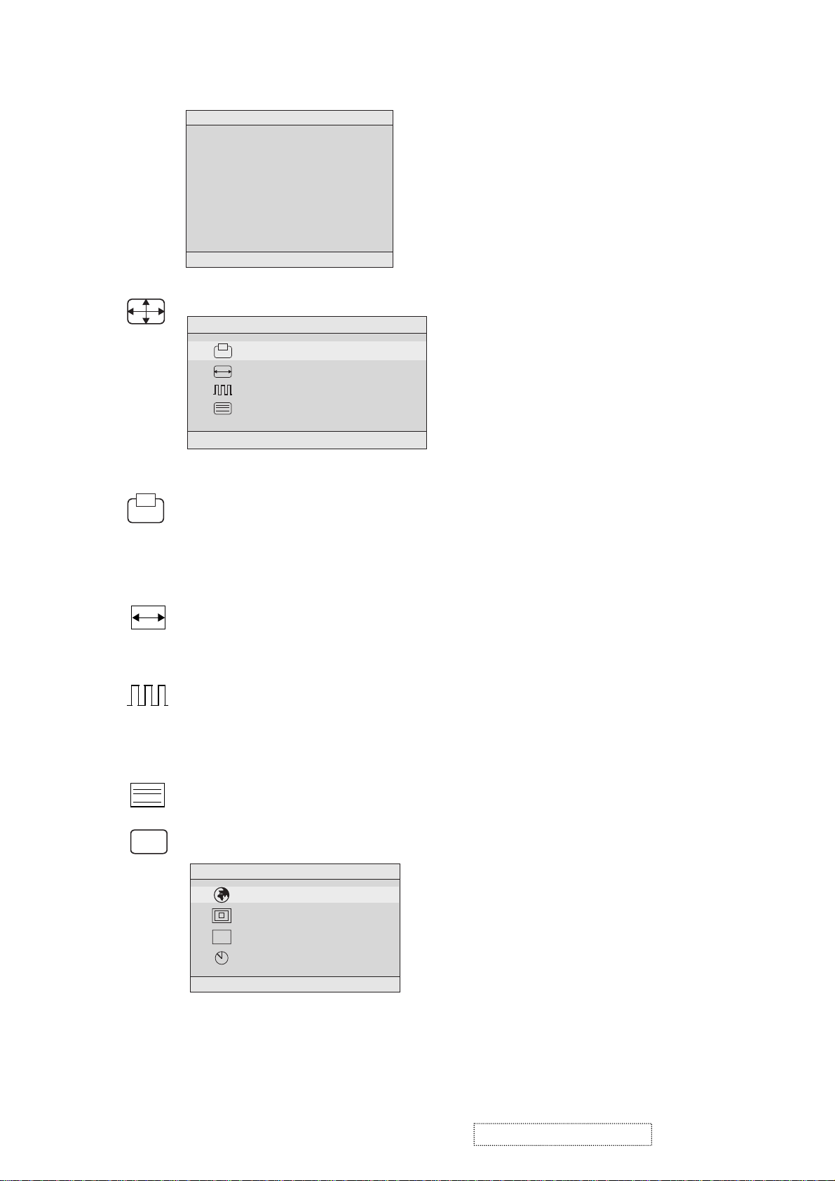
Image Adjust
Image Adjust
H./V. Position
H. Size
Fine Tune
Sharpness
1:EXIT 2:SELECT
The Image Adjust controls are explained below:
?
H./V. Position
adjusts horizontal and vertical position of the
screen image. You can toggle between Horizontal and Vertical
by pressing button [2]. Horizontal moves the screen image to
the left or to the right. Vertical moves the screen image up and
down.
H. Size
NOTE:
Fine Tunesharpens focus by aligning the illuminated text and/
(Horizontal Size) adjusts the width of the screen image.
Vertical size is automatic with your LCD display.
or graphic characters.
NOTE:TrytheAuto Adjustbefore using the Fine
Tune control.
Sharpness
Setup Menu displays the menu shown below.
OSD
adjusts the clarity and focus of the screen image.
Setup Menu
Language Select
Resolution Notifier
OSD Position
OSD Timeout
1:EXIT 2:SELECT
The Setup Menu controls are explained below.
ViewSonic Corporation Confidential
8
-
Do Not Copy VA521
VE510b/s-2
Page 12
L
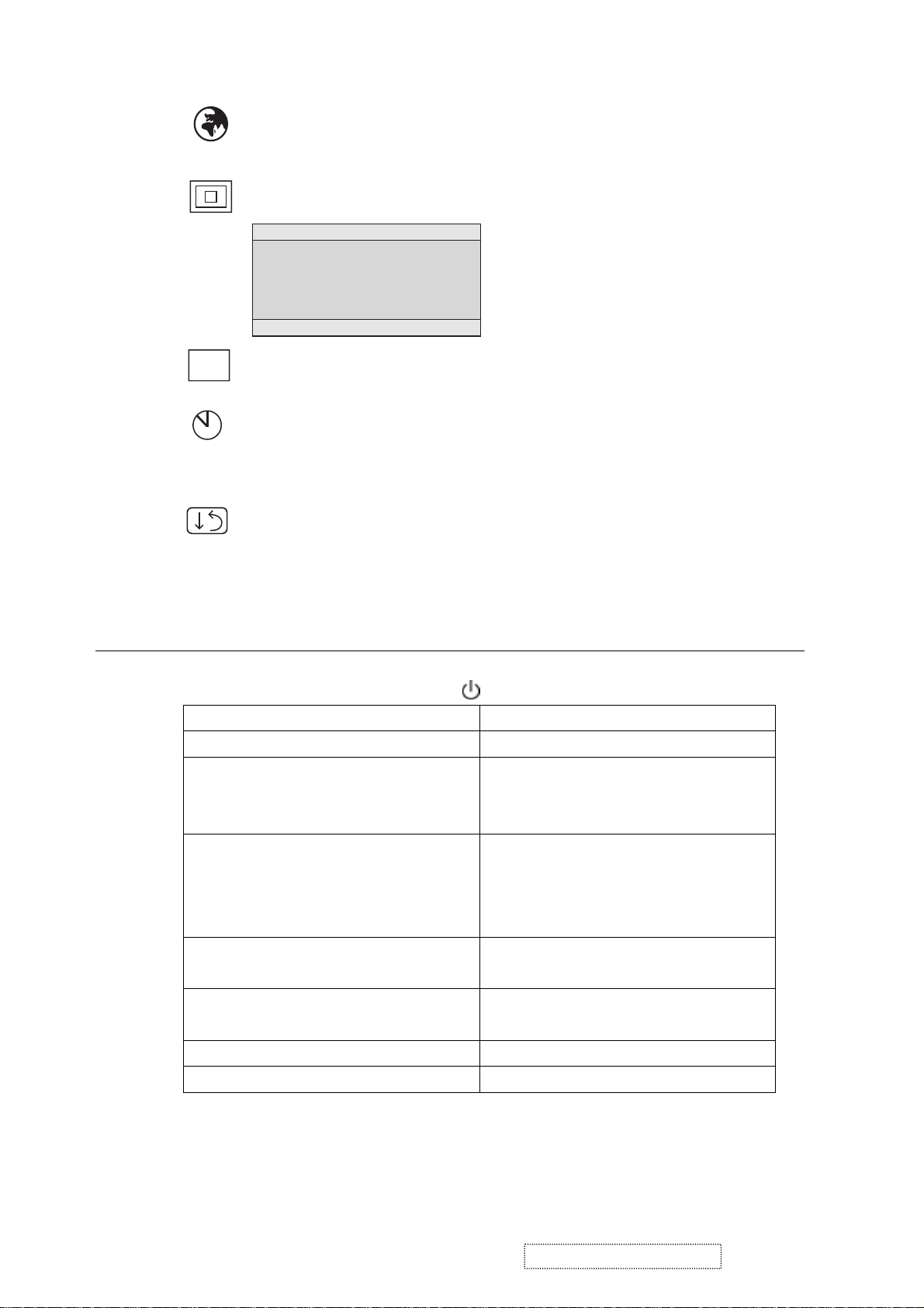
anguage
Selectallowsyoutochoosethelanguageusedin
the menus and control screens.
OSD
Short Cut Key
Function Key : 5 Keys !!!! 1 2 ▼
Resolution Notice
Resolution Notice
For best picture quality
change the resolution to
1024 x 768
1:EXIT 2:DISABLE
OSD Position
advises the optimal resolution to use.
allows you to move the on-screen display menus
and control screens.
OSD Timeout
sets the length of time an on-screen display
screen is displayed. For example, with a “15 second” setting, if
a control is not pushed within 15 seconds, the display screen
disappears.
Memory Recall
returns adjustments to the original factory
settings if the display is operating in a factory Preset Timing
Mode listed in this user guide.
▲▲▲▲
▼▼▼
[1] Main Menu
[2] Auto Image Adjust
[▼▼▼▼] or [▲▲▲▲]
to immediately activate Contrast menu.
It should be change to Brightness OSD
by push button [2].
[▼▼▼▼] + [▲▲▲▲]
recall Contrast or Brightness while in
the Contrast or Brightness adjustment,
or recall both of Contrast and
Brightness when the OSD is not open.
[1] + [2] toggle 720x400 and 640x400 mode when
input 720x400 or 640x400 mode.
[1] + [▼▼▼▼] + [▲▲▲▲]
(Keep pushing 5 sec)
[1] + [▼▼▼▼]
[1] + [▲▲▲▲]
White Balance.
Power Lock
OSD Lock
ViewSonic Corporation Confidential
9
-
Do Not Copy VA521
VE510b/s-2
Page 13

4. Circuit Description
4-1 DC-DC CONVERTER
The power supply with integrated green-mode PWM controller provides several features to enhance the
performance of power fly back converters.
I801 is a PWM controller and provides many protection functions.
I802 is a photo couple to transfer the feedback signal from the secondary side, where I803 detects the output DC
voltage of 3.3V and 12V.
D813 detects the working voltage on I801. Q805 is used to pull down the voltage on I801 pin5 and shut down I801
in case the feedback loop fails.
R826 is a dynamic load for the inverter, while backlight is turned off, but the system is still working. This keeps
the 12V output voltage under 13V,
no longer loaded. This is detected by I804 and Q803, to activate the R826.
4-2 Scaling controller
The ADC converts the RGB analog signal to a digital signal that the scaling chip can acknowledge.
The HSYNC input receives a logic signal and provides the frequency reference for pixel clock generation.
The scaling IC converts the input signal ranging from VGA to XGA into XGA resolution that the panel can
acknowledge.
GENERAL DESCRIPTION
The MST8016A is a high performance, and fully integrated graphics processing IC solution for LCD monitors with
resolutions up to XGA. It is configured with an integrated triple-ADC/PLL, a high quality scaling engine, an
on-screen display controller, a built-in output clock generator, a panel timing controller (TCON), and RSDS display
interface. To further reduce system costs, the MST8116A also integrates intelligent power management control
capability for green-mode requirements and spread-spectrum support for EMI management.
4-3 MTV312M64
The MTV312M micro-controller is an 8051 CPU core embedded device especially tailored for CRT/LCD
Monitor applications. It includes an 8051 CPU core, 1024-byte SRAM, 14 built-in PWM DACs, VESA DDC
interface, 4-channel A/D converter, and a 64K-byte internal program Flash-ROM.
A “CMOS output pin” means it can sink and drive at least 4mA current. It is not recommended to use such
pin as input function.
A “open drain pin” means it can sink at least 4mA current but only drive 10~20uA to VDD. It can be used as input
or output function and needs an external pull up resistor.
A “8051 standard pin” is a pseudo open drain pin. It can sink at least 4mA current when output is at low level, and
drive at least 4mA current for 160nS when output transits from low to high, then keeps driving at 100uA to
maintain the pin at high level. It can be used as input or output function. It needs an external pull up resistor when
driving heavy load device.
POWER CONFIGURATION
The MTV312M can work on 5V or 3.3V power supply system.
In 5V power system, the VDD pin is connected to 5V power and the VDD3 needs an external capacitor, all
output pins can swing from 0~5V, input pins can accept 0~5V input range.
The ADC conversion range is 5V. However, X1 and X2 pins must be kept below 3.3V.
In 3.3V power system, the VDD and VDD3 are connected to 3.3V power, all output pins swing from 0~3.3V,
HSYNC, VSYNC and open drain pin can accept 0~5V input range, other pins must be kept below 3.3V. The
ADC conversion range is 3.3V.
to protect the panel. After
system enters the power saving mode, R826 is
ViewSonic Corporation Confidential
10
-
Do Not Copy VA521
VE510b/s-2
Page 14

4-4 INVERTER
In order to drive the CCFLs embedded in the panel module, there is a push-pull inverter to convert 12Vdc
up to hundreds of volts AC .
The inverter is formed by symmetric outputs in order to drive the separate lamp modules.
The input stage consists of a PWM controller, push-pull inverter, and switching MOSFET to convert the DC input into
AC output.
The output stage consists of a tuning capacitor, transformer, and push-pull MOSFET pair to boost the AC output up to
the required level. One resistor is used in series with the lamp for output voltage feedback.
There are two signals from the system to turn on the inverter and control brightness.
A Logic “low” level to I901 is used to turn on the inverter.
The signal BRI controls brightness by a DC level from, the PWM signal.
ViewSonic Corporation Confidential
11
-
Do Not Copy VA521
VE510b/s-2
Page 15

5. Adjusting Procedure
5.1 ADJUSTMENT CONDITIONS AND PRECAUTIONS
.
Approximately 30 minutes should be allowed for warm up before proceeding.
.
Adjustments should be undertaken only on those necessary elements since most of them have been carefully
preset at the factory.
.
ESD protection is needed before adjustment.
5.2 MAIN ADJUSTMENTS
NO. FUNCTION DESIGNATION
.
V-com Voltage On the back of the Panel
.
eprom Initial Function Key
.
White Balance Function Key
5.3 ALIGNMENT PROCEDURES
Adjustment Conditions and Precautions:
(A). Power supply voltage:
AC 110/120V±10% 60 Hz±5%, AC 220/240V± 10% 50 Hz ±5%.
(B). Warm up time:
The display must be power ON for at least 30 minutes at full white pattern before starting alignments.
This is especially critical in color temperature and white balance adjustments.
(C). Signals: reference the front detail specifications and timing table.
Video : reference the front detail specifications.
.
Adjustment of V-com Voltage:
A. Timing : 1024x768@60Hz. 48KHz
B. Pattern : The picture of “ Shut down windows” or Full screen pixel ON/OFF pattern.
C. Adjust V-com to let the center of the screen no flash.
.
Eeprom Initial:
A. Timing : 1024x768@60Hz.
B. Pattern : Cross hatch.
C. Switch off the power and press the “ ” and “ 2 “ key simultaneously, then switch on the power. At
this time we can enter into the factory mode when press the “ 1 “key.
D. Select the “EEPROM INIT” item and press “ 2 “key to reset the Eeprom.
.
White Balance Adjustment :
A. Timing : 1024x768@60Hz.
B. Pattern : 16Gray Level. or 5-MOSAIC (Pattern 42)
C. Set CA210 color analizer at the center of screen and along a perpendicular to the screen at 0cm from
the display.
D. Move “ ” key to select the “ WHITE BALANCE” item in the factory mode and press “ 2 “key, then
E. Color temperature verification: (Set Brightness and Contrast to Maximum)
6500K verify : press “ ” ,“ ” key to move cursor to 6500K at factory mode
and press “ 2 “ key, and then check the color temperature is
x=0.312 ±0.03
y=0.318 ±0.03
Y≧200 cd/m
▼
the white balance will be auto adjusted.
▲
▲
▼
2
ViewSonic Corporation Confidential
12
-
Do Not Copy VA521
VE510b/s-2
Page 16

6. Trouble Shooting Flow Chart
6.1 NO POWER or BACKLIGHT
Check main board
backlight_on signal
Check Q903,D905
Check R926,F901
broken or not
Check Q905.
Check I901,I902,
R905,R905
No
No
Check I901 pin1 voltage
No
NO POWER
Yes
3.3V on P801
pin5,6 to GND
12V on P802
pin3 to GND
Yes Yes
NO BACKLIGHT.
Check P802 pin2 with
3.3V or not
Yes
Check 5V on I901 pin6
Yes
>0.55volts,<3.70volts
while inverter turn on
With power
but power saving mode more
than 1 Watts
No
CHECK C805
with voltage more than
150volts or not
Check R813~R815 broken or
Check Q802,D813 failed or not
Check I802,I803
not
Yes
No
Yes
No
No
with main board more than
1Watts
check main board.
CHECK
D801~D804 failed or not,
F801 broken or not,
R802 broken or not
Check Q801 D & S short or
not,I801 failed,
R807 broken or not
Check Q903,I804
without connecting main board,
Yes
Check
Q901,Q902,D903,D904
No
Check D809,D811.
Check D810,If power board
with audio amplifier
ViewSonic Corporation Confidential
13
-
Do Not Copy VA521
VE510b/s-2
Page 17

6.2 NO DISPLAY
No
Display
Check Power
region
Refer to NO POWER
trouble shoot flow char
Check LED Color
Green
Press Power key
ON/OFF is OK ?
(See LED is green or
dark.)
Yes
Press "1" key if OSD
menu is on display ?
Yes
Check I105
MST8016 if HWRST
Pin#32 have
reset pulse ?
Yes
AmberDark
Amber & Green
No
No
No
Check IO cable is
Check X301 Crystal
12MHz is working?
Check uP I106
Check Keypad
Inverter is Ok ?
Check uP I106
pin#17 send reset
Yes
connect OK ?
Yes
Reset is Ok ?
pcb is OK ?
Yes
Check if
pulse ?
No
Yes
Yes
Check I/P signal is in
pwr saving state?
Check I106 is OK ?
Check Reset circuit
No
No
Change
I106
C173,D125
Change
Inverter
Check X101 Crystal
12MHz is working ?
Yes
Check I105
Pin#70,71 data bus
have signal
Yes
Check panel Powers
VLCD_3V3
VLCD_12V
correct
Yes
Change LCD panel
No
No
Change X101
Change I001 LCD
controller IC
ViewSonic Corporation Confidential
14
-
Do Not Copy VA521
VE510b/s-2
Page 18

VA521 RSPL
Rev 1a
POWER CORD (GERMAN WALL 1.83M BLACK SCP )
7. Recommended Spare Parts List
VA521 Recommended spare Parts List
Item ViewSonic P/N Ref. P/N Description Location Q'ty
1 P-BX-0601-0946 2011121001 CARTON BOX 6P01 1
2 P-FM-0602-0855 2012176900 POLYFOAM 6P20 1
3 P-FM-0602-0856 2012177000 POLYFOAM 6P21 1
4 M-MS-0808-0027 2013150901 PE bag 6P60 1
5 M-MS-0808-1316 2013222536 POLYETHY BAG 250mmx350mmxt0.3 ADD>PE-LD<
6 C-BC-0302-0583 2022262202 CABI BACK ABS 94HB PANTONE BLACK C=4001
7 PL-PS-0715-0986 2028258002 STAND 5B01 1
8 M-SCW-0824-0285 2084730082 SCREW,BND T+ 2C22 9S01 7
9 M-LCD-0826-0210 2212004700 LCD PANEL V901 1
10 E-FS-0410-0009 2213125207 FUSE F801 1
11 A-VIO-0118-0034 2427501174 I/O CABLE P961 1
12 A-CD-VA521 2438501135 CD wizard VA521 WIZARD DATE:2003 6P80 1
13 C-FP-0301-0965 2603307566 Front enclosure 1
14 C-FP-0301-0966 2024266702 FRONT BEZEL ABS 94 HB PS-7604B
15 M-MS-0808-9211 2002310369 GUARANT CARD VIEWSONIC VA521 QSG
16 M-LB-0813-0528 2055103400 DATE LABEL :JK0936F WEN 6P52 1
17 M-CV-0830-0281 2027258402 DUST COVER ABS 94HB
18 PL-PD-0714-0113 2039819301 FOOT PAD RUBBER O20*2TMM SQUARE GRAIN
19 PL-FK-0709-0151 2044266102 FUNCTION KEY ABS 94hb
20 M-MS-0808-9213 2051352000 NAME PLATE :VIEWSONIC LOGO 3 PIN VA521
21 M-MS-0808-9214 2051352100 NAME PLATE:VIEWSONIC E015-006 3-BIRD LOGO
22 M-MS-0808-9215 2051352200 NAME PLATE:VIEWSONIC E015-017
23 M-LB-0813-0926 2055131793 LABEL:VA521 VLCDS27996-1W PSB-MARK
24 M-LB-0813-0769 2055613293 LABEL:VIEWSONIC OPEN STAND LABEL-LCD
25 M-LB-0813-0856 2055613379 LABEL:ViewSonic CONTAINER LABEL
26 M-LB-0813-0928 2055632038 LABEL:VA521 VLCDS27996-1W
27 M-LB-0813-0927 2055636019 LABEL:VA521 VLCDS27996-1W SMALL
28 M-LB-0813-0002 2056603050 SERIAL LABEL:VIEWSONIC LCD SERIAL LABEL
29 M-MS-0808-9217 2106656301 HINGE:VA521 -5'~+20' (T.L)
30 M-LCD-0826-0210 2212004700 LCD PANEL:CLAA150XG08 CPT
31 M-MS-0808-9218 2434410300 AL SHIELDING TAPE:W25*L30mm*T0.06 (AL)
32 B-MB-0201-0833 6201-7956908101 PCB ASS'Y BLOCK (MAIN)
33 B-CB-0206-0177
34 B-PS-0204-0066 6204-7956908101 PCB ASS'Y BLOCK (POWER)
6202-7956908101
PCB ASS'Y BLOCK (CON)
6P85
2C01
1F01
6P84
5B07
5B03
1F03
1F04
1F05
2C02
6P50
5B10
6P11
6P02
6P05
6P56 6P55 6P54 6P51
2C20 RB
V901
K901
1
1
1
1
2
5
1
1
1
1
1
1
10
1
1
4
1
1
1
1
1
1
VA521 RSPL - VSA , VSI Rev 1a
Item ViewSonic P/N Ref. P/N Description Location Q'ty Lead time
1 A-PC-0106-0121 2427130046 POWER CORD:USA WALL 1.83M BLACK P951 1 30
VA521 RSPL - VSCN-G Rev 1a
Item ViewSonic P/N Ref. P/N Description Location Q'ty Lead time
1 A-PC-0106-0277 2427130097 POWER CORD ( CHINA WALL 1.83M BLACK SCP) P951 1 30
2 M-LB-0813-0929 2055632046 UPC LABEL VA521 VLCDS27996-1W CHINA 6P02 1 30
3 M-MS-0808-0028 2002310338 GUARANT CARD VIEWSONIC CHINA WARRANTY CARD 6P07 1 30
4 M-LB-0813-0930 2056606021 SERIAL LABEL VS WARRANTY CARD SERIAL NO-J 6P08 1 30
5 M-LB-0813-0863 2056606010 SERIAL LABEL VIEWSONIC BOX STICKER-G 6P12 1 30
6 M-LB-0813-0864 2056606009 SERIAL LABEL VIEWSONIC SERVICE STICKER-G 6P15 1 30
7 M-MS-0808-0033 2013051800 POLYETHY BAG JT166A14 500LX470WX490H t=0.08 6P70 1 30
VA521 RSPL - VSE-EUROPE Rev 1a
Item ViewSonic P/N Ref. P/N Description Location Q'ty Lead time
1 A-PC-0106-0138 2427130047
P951 1 30
2 M-LB-0813-0931 2055632054 UPC LABEL VA521 VLCDS27996-1W EUROPE 6P02 1 30
ViewSonic Corporation Confidential
15
-
Do Not Copy VA521
VE510b/s-2
Page 19

POWER CORD (CHINA WALL 1.83M BLACK SCP)
POWER CORD (GERMAN WALL 1.83M BLACK SCP )
VE510b-2 Recommended spare Parts List
VE510b-2 RSPL Rev 1a
Item ViewSonic P/N Ref. P/N Location Q'ty
1 M-MS-0808-9395 2002310388 GUARANT CARD VIEWSONIC VE510B-2 QSG 6P84 1
2 P-BX-0601-0969 2011100010 CARTON BOX -pallet 6P90 1
3 P-BX-0601-0970 2011121004 CARTON BOX 6P01 1
4 P-FM-0602-0855 2012176900 POLYFOAM 6P20 1
5 P-FM-0602-0856 2012177000 POLYFOAM 6P21 1
6 M-MS-0808-0027 2013150901 POLYETHY BAG 6P60 1
7 M-MS-0808-1316 2013222536 POLYETHY BAG 250mmx350mmxt0.3 ADD>PE-LD< 6P85 1
8 C-BC-0302-0597 2022262203 CABI BACK ABS 94HB MIDNIGHT GRAY 2C01 1
9 C-FP-0301-0991 2024266704 FRONT BEZEL ABS 94HB MIDNIGHT GRAY 1F01 1
10 M-CV-0830-0281 2027258402 DUST COVER VA521 ABS 94HB AL-PALTE 5B07 2
11 PL-PS-0715-0992 2028258003 STAND ABS 94HB MIDNIGHT GRAY 5B01 1
12 PL-PD-0714-0113 2039819301 FOOT PAD RUBBER O20*2TMM SQUARE GRAIN 5B03 5
13 PL-FK-0709-0151 2044266102 FUNCTION KEY VA521 ABS 94HB AL-PLATE 1F03 1
14 M-MS-0808-9213 2051352000 NAME PLATE VIEWSONIC LOGO 3 PIN VA521 1F04 1
15 M-MS-0808-9214 2051352100 NAME PLATE VIEWSONIC E015-006 3-BIRD LOGO 1F05 1
16 M-MS-0808-9396 2051352202 NAME PLATE NAME PLATE VIEWSONIC E015-027 2C02 1
17 M-MS-0808-9397 2053753701 LED INDIC.-PWR VA521 PMMA 94HB 1F02 1
18 M-LB-0813-0528 2055103400 LABEL JK0936F WEN 6P52 1
19 M-LB-0813-0980 2055131807 LABEL VE510B-2 VLCDS27996-3W 6P50 1
20 M-LB-0813-0855 2055613281 LABEL VIEWSONIC VA520 NUMBER STICKER 6P03 1
21 M-LB-0813-0769 2055613293 LABEL VIEWSONIC OPEN STAND LABEL-LCD 5B10 1
22 M-LB-0813-0856 2055613379 LABEL ViewSonic CONTAINER LABEL 6P11 1/96
23 M-LB-0813-0959 2055613392 LABEL VSC HIGH VOLTAGE WARNING LABEL 6P14 1
24 M-LB-0813-0530 2055617101 LABEL 10*20 HI-POT TESTED 0K 6P13 1
25 M-LB-0813-0981 2055632063 LABEL VE510B-2 VLCDS27996-3W (M) 6P02 1
26 M-LB-0813-0982 2055636024 LABEL VE510B-2 VLCDS27996-3W SMALL 6P05 1
27 M-LB-0813-0002 2056603050 SERIAL LABEL VIEWSONIC LCD SERIAL LABEL 6P56 6P55 6P54 6P51 4
28 M-MS-0808-9216 2106656300 HINGE VA521 -5°~ + 20°(F.S) 2C20 RA 1
29 M-MS-0808-9217 2106656301 HINGE VA521 -5°~+20° (T.L) 2C20 RB 1
30 M-LCD-0826-0223 2212004701 LCD PANEL V902 1
31 A-PC-0106-0121 2427130046 POWER CORD P951 1
32 A-CD-VE510 2438501148 CD-OWNER GUIDE 6P81 1
33 B-MB-0201-0853 6201-7956908251 PCB ASS'Y BLOCK (MAIN) 1
34 B-CB-0206-0177 6202-7956908101 PCB ASS'Y BLOCK (CON) 1
35 B-PS-0204-0066 6204-7956908101 PCB ASS'Y BLOCK (POWER) 1
Description
VE510b-2 RSPL VSCN Rev 1a
Item ViewSonic P/N Ref. P/N Description Location Q'ty
1 A-PC-0106-0277 2427130097
2 M-MS-0808-9357 2051352201 NAME PLATE VIEWSONIC E012-019 2C02 1
3 M-MS-0808-9400 2055632065 VE510B-2 VLCDS27996-3W(G) 6P02 1
4 M-MS-0808-0028 2002310338 VIEWSONIC CHINA WARRANTY CARD 6P07 2
5 M-LB-0813-0862 2056606025 VS CN WARRANTY CARD SN STICKER 6P08 1
6 M-LB-0813-0984 2002201323 VIEWSONIC CRT QUALIFIED LABEL 6P09 1
7 M-LB-0813-0863 2056606010 VIEWSONIC BOX STICKER-G 6P12 1
8 M-LB-0813-0864 2056606009 VIEWSONIC SERVICE STICKER-G 6P15 1
9 M-MS-0808-0033 2013051800 POLYETHY JT166A14 500LX470WX490H t=0.08 6P70 1
VE510b-2 RSPL VSE Rev 1a
Item ViewSonic P/N Ref. P/N Description Location Q'ty
1 A-PC-0106-0138 2427130047
2 M-LB-0813-0983 2055632067 VE510B-2 VLCDS27996-2W (E) UPC label 6P02 1
P951 1
P951 1
ViewSonic Corporation Confidential
16
-
Do Not Copy VA521
VE510b/s-2
Page 20

VE510s-2 Recommended spare Parts List
VE510s-2 RSPL Rev 1a
Item ViewSonic P/N Ref. P/N Description Location Universal number# Q'ty
1 M-MS-0808-9407 2002310387 GUARANT CARD VIEWSONIC VE510S-2 QSG 6P84 1
2 P-BX-0601-0969 2011100010 CARTON BOX - PALLET 6P90 1
3 P-BX-0601-0972 2011121003 CARTON BOX 6P01 1
4 P-FM-0602-0855 2012176900 POLYFOAM 6P20 1
5 P-FM-0602-0856 2012177000 POLYFOAM 6P21 1
6 M-MS-0808-0027 2013150901 PE bag 6B60 1
7 M-MS-0808-1316 2013222536 POLYETHY BAG 250mmx350mmxt0.3 ADD>PE-LD< 6P85 1
8 C-BC-0302-0583 2022262202 CABI BACK 2C01 1
9 C-FP-0301-0993 2024266703 FRONT BEZEL ABS 94HB PS-7604B/C4001 1F01 1
10 M-CV-0830-0281 2027258402 DUST COVER VA521 ABS 94HB AL-PALTE 5B07 2
11 PL-PS-0715-0986 2028258002 STAND ABS94HB PANTONE BLACK C=4001 5B01 1
12 PL-FK-0709-0151 2044266102 FUNCTION KEY VA521 ABS 94HB AL-PLATE 1F03 1
13 M-MS-0808-9213 2051352000 NAME PLATE VIEWSONIC LOGO 3 PIN VA521 1F04 1
14 M-MS-0808-9214 2051352100 NAME PLATE VIEWSONIC E015-006 3-BIRD LOGO 1F05 1
15 M-MS-0808-9215 2051352200 NAME PLATE VIEWSONIC E015-017 2C02 1
16 M-LB-0813-0528 2055103400 LABEL JK0936F WEN 6P52 1
17 M-LB-0813-0985 2055131806 LABEL VE510S-2 VLCDS27996-2W 6P50 1
18 M-LB-0813-0855 2055613281 LABEL VIEWSONIC VA520 NUMBER STICKER 6P03 1
19 M-LB-0813-0769 2055613293 LABEL VIEWSONIC OPEN STAND LABEL-LCD 5B10 1
20 M-LB-0813-0856 2055613379 LABEL CONTAINER 6P11 1
21 M-LB-0813-0959 2055613392 LABEL VSC HIGH VOLTAGE WARNING LABEL 6P14 1
22 M-LB-0813-0530 2055617101 LABEL 10*20 HI-POT TESTED 0K 6P13 1
23 M-LB-0813-0986 2055632062 LABEL VE510S-2 VLCDS27996-2W (M) UPC 6P02 1
24 M-LB-0813-0987 2055636023 LABEL VE510S-2 VLCDS27996-2W SMALL 6P05 1
25 M-LB-0813-0002 2056603050 SERIAL LABEL VIEWSONIC LCD SERIAL LABEL 6P56 6P55 6P54 6P51 4
26 M-MS-0808-9408 2061453400 BUSHING VE710 PLUG RUBBER 2C04 1
27 M-SCW-0824-0285 2084730082 SCREW,BND T+ 2C22 1
28 M-MS-0808-9216 2106656300 HINGE VA521 -5~° + 20° (F.S) 2C20 RA 1
29 M-MS-0808-9217 2106656301 HINGE VA521 -5°~+20° (T.L) 2C20 RB 1
30 M-LCD-0826-0223 2212004701 LCD PANEL V901 1
31 A-PC-0106-0121 2427130046 POWER CORD('USA WALL 1.83M BLACK SCP ) P951 1
32 A-CD-VE510 2438501147 CD-OWNER GUIDE VE510S-2 WIZARD DATE:20040205 1
33 B-MB-0201-0854 6201-7956908252 PCB ASS'Y BLOCK (MAIN) 1
34 B-CB-0206-0177 6202-7956908101 PCB ASS'Y BLOCK (CON) 1
35 B-PS-0204-0066 6204-7956908101 PCB ASS'Y BLOCK (POWER) 1
VE510s-2 VSA-E RSPL Rev 1a
Item ViewSonic P/N Ref. P/N Description Location Universal number# Q'ty
1 A-PC-0106-0138 2427130047 POWER CORD ( GERMAN WALL 1.83M BLACK SCP ) P951 1
2 M-MS-0808-9409 2055632066 VE510S-2 VLCDS27996-2W (E) 6P02 1
VE510s-2 VSCN-G RSPL Rev 1a
Item ViewSonic P/N Ref. P/N Description Location Universal number# Q'ty
1 A-PC-0106-0277 2427130097 POWER CORD( CHINA WALL 1.83M BLACK SCP) P951 1
2 M-MS-0808-9410 2055632064 VE510S-2 VLCDS27996-2W(G) 6P02 1
3 M-MS-0808-0028 2002310338 VIEWSONIC CHINA WARRANTY CARD 6P07 1
4 M-LB-0813-0862 2056606025 VS CN WARRANTY CARD SN STICKER 6P08 2
5 M-LB-0813-0984 2002201323 VIEWSONIC CRT QUALIFIED LABEL (QA O.K.) 6P09 1
6 M-LB-0813-0863 2056606010 VIEWSONIC BOX STICKER-G 6P12 1
7 M-LB-0813-0864 2056606009 VIEWSONIC SERVICE STICKER-G 6P15 1
8 M-MS-0808-0033 2013051800 POLYETHY JT166A14 500LX470WX490H t=0.08 6P70 1
ViewSonic Corporation Confidential
17
-
Do Not Copy VA521
VE510b/s-2
Page 21

VA521 BOM Parts List
VA521 BOM LIST Rev 1a
Item ViewSonic P/N Ref. P/N Location Q'ty
1 M-MS-0808-9211 2002310369 GUARANT CARD VIEWSONIC VA521 QSG
2 P-BX-0601-0946 2011121001 CARTON BOX VA521 VLCDS27996-1W
3 P-FM-0602-0855 2012176900 POLYFOAM VA521 EPS (L)
4 P-FM-0602-0856 2012177000 POLYFOAM VA521 EPS (R)
5 M-MS-0808-0027 2013150901 POLYETHY BAG 700LX600WX0.03tmm PE-LD ADD>PE
6 M-MS-0808-1316 2013222536 POLYETHY BAG 250mmx350mmxt0.3 ADD>PE-LD<
7 C-BC-0302-0583 2022262202 CABI BACK ABS 94HB PANTONE BLACK C=4001
8 C-FP-0301-0966 2024266702 FRONT BEZEL ABS 94 HB PS-7604B
9 M-CV-0830-0281 2027258402 DUST COVER ABS 94HB
10 PL-PS-0715-0986 2028258002 STAND ABS94HB PANTONE BLACK C=4001
11 PL-PD-0714-0113 2039819301 FOOT PAD RUBBER O20*2TMM SQUARE GRAIN
12 PL-FK-0709-0151 2044266102 FUNCTION KEY ABS 94hb
13 M-MS-0808-9213 2051352000 NAME PLATE VIEWSONIC LOGO 3 PIN VA521
14 M-MS-0808-9214 2051352100 NAME PLATE VIEWSONIC E015-006 3-BIRD LOGO
15 M-MS-0808-9215 2051352200 NAME PLATE VIEWSONIC E015-017
16 #N/A 2053753701 LED INDIC.-PWR VA521 PMMA 94HB
17 M-LB-0813-0530 2055617101 LABEL Hi-POT tested O.K. label
18 #N/A 2055613392 LABEL High Voltage warning
19 M-LB-0813-0528 2055103400 LABEL JK0936F WEN
20 M-LB-0813-0926 2055131793 LABEL VA521 VLCDS27996-1W PSB-MARK
21 M-LB-0813-0769 2055613293 LABEL VIEWSONIC OPEN STAND LABEL-LCD
22 M-LB-0813-0856 2055613379 LABEL ViewSonic CONTAINER LABEL
23 M-LB-0813-0928 2055632038 LABEL VA521 VLCDS27996-1W
24 M-LB-0813-0927 2055636019 LABEL VA521 VLCDS27996-1W SMALL
25 M-LB-0813-0002 2056603050 SERIAL LABEL VIEWSONIC LCD SERIAL LABEL
26 M-MS-0808-9220 2071668700 SHIELD PLATE SPTE T=0.3MM FOR MAIN BOARD
27 M-MS-0808-9222 2071670400 SHIELD PLATE SPTE T=0.3MM (TOP)
28 M-MS-0808-9223 2071670500 SHIELD PLATE SPTE T=0.3MM (DOWN)
29 #N/A 2071869400 BRACKET,FIX METAL PLATE 1.0MM KENSINGTON
30 M-MS-0808-9212 2071969000 METAL FITTG SECC T=0.8MM FOR CPT VA521
31 M-MS-0808-9225 2071969200 METAL FITTG SECC T=1MM STAND
32 #N/A 2072260600 HEAT SINK AL 25*20*1.5T
33 M-MS-0808-9219 2072456900 INSULATOR MYLAR BLACK 94V0 T=0.5 POWER
34 M-MS-0808-9221 2072457000 INSULATOR MYLAR BLACK 94V0 T=0.5 SIGNAL
35 #N/A 2072457300 INSULATOR MYLAR BLACK 94V0 T=0.5 BOTTOM
36 M-SCW-0824-6715 2080002200 SCREW,SPE L355 M3x6 DH NICKEL-PLATED
37 M-SCW-0824-6717 2081430062 SCREW,(WASH) M3X6 P=0.5(TOOTH WASHER)
38 M-SCW-0824-6719 2082630062 SCREW M3X6 P=0.5
39 M-SCW-0824-0812 2084730062 SCREW,BND T+ M3X6(BND T+)
40 M-SCW-0824-0285 2084730082 SCREW,BND T+ M3X8(BND T+)
41 M-SCW-0824-0123 2084740102 SCREW,BND T+ M4X10(BND T+)
42 M-SCW-0824-6745 2084740104 SCREW,BND T+ M4X10(BND T+) (BLK)
43 M-SCW-0824-0517 2085730062 SCREW,B OTW+ 3X6(+) SWRM-3 ZMC2-C
44 M-SCW-0824-6820 2085740062 SCREW,B OTW+ B,OTW+,M4x6
45 M-SCW-0824-0440 2085740102 SCREW,B OTW+ SCREW B OTW+ M4X10
46 M-MS-0808-0854 2097400301 EYELET BSS3-1/2H T=0.25 SN 3µm
47 #N/A 2105251400 SPRING PLATE SPTE T=0.4MM (GROUND PLATE)
48 M-MS-0808-9224 2105251600 SPRING PLATE VA521 PB-CU T=0.2MM
49 M-MS-0808-9216 2106656300 HINGE VA521 -5度~ + 20度(F.S) 1
50 M-MS-0808-9217 2106656301 HINGE VA521 -5'~+20' (T.L)
51 #N/A 2202126900 PC BOARD JT166RSDS PRW CEM1 160*100
52 #N/A 2202127100 PC BOARD VA521 KEY/B FR1 115*31
53 #N/A 2202516000 PCB MULTILAYER VA210 M/B FR4*2 80*100
54 M-LCD-0826-0210 2212004700 LCD PANEL CLAA150XG08 CPT
55 E-FS-0410-0009 2213125207 FUSE FUSE 2.5A/250V 21502.5 LITTEL
56 E-FS-0410-0102 2213125211 FUSE FUSE 2.5A/250V SG501302.5 PICO
57 E-TH-0416-0042 2229201212 THERMISTOR,PTH SCK-103 10+-20% 3A THINKING
58 #N/A 2232412295 RES,CBN 1/4 RD 1/4W 1.2Kohm P=10.0 J T
59 #N/A 2232491495 RES,CBN 1/4 RD 1/4W 910Kohm P=7.5 J T
60 #N/A 2232656395 RES,CBN 1/2 RD 1/2W 56Kohm J T52
61 E-R-0405-3443 2233447995 RES,CBN 1/4 S RD 1/4WS 4.70 J T52 MINI
62 #N/A 2235647013 RES,MTL 3 RS 3WS 47ohm J P=20.0
63 #N/A 2242330595 HIGH VOLTAGE RESISTOR RD 1/2W 3.00M J
64 #N/A 2251239006 RES,CHIP 1/10 RC 0603 1/10W 390 ohm F T
65 #N/A 2251275096 RES,CHIP 1/10 RC 0603 1/10W 75 ohm F T
66 #N/A 2251310006 RES,CHIP 1/8 RC 0805 1/8 W 100 ohm F T
67 #N/A 2251310036 RES,CHIP 1/8 RC 0805 1/8 W 100Kohm F T
68 #N/A 2251318026 RES,CHIP 1/8 RC 0805 1/8 W 18Kohm F T
69 #N/A 2251320026 RES,CHIP 1/8 RC 0805 1/8 W 20Kohm F T
70 #N/A 2251322016 RES,CHIP 1/8 RC 0805 1/8 W 2.2Kohm F T
71 #N/A 2251327416 RES,CHIP 1/8 RC 0805 1/8 W 2.74Kohm F T
72 #N/A 2251340206 RES,CHIP 1/8 RC 0805 1/8W 402 ohm F T
73 #N/A 2251341206 RES,CHIP 1/8 RC 0805 1/8W 412 ohm F T
Description
6P84
6P01
6P20
6P21
6P60
6P85
2C01
1F01
5B07
5B01
5B03
1F03
1F04
1F05
2C02
1F02
1F21
P951
6P52
6P50
5B10
6P11
6P02
6P05
6P56 6P55 6P54 6P51
1F16
1F21
1F22
2C03
1F11
5B02
9H01
1F12
1F20
1F13
1F14
1F19
1F17 1F23
5B05
9S01 2C22
5B04
2C23
1F18
1F15
5B06
E801 E802 E803
9H10
2C21
2C20 RA
2C20 RB
U801
U701
U101
V901
F801 RA
F801 RB
R802
R824
R804 R805
R806
R901 R902
R826
R917
R140
R113 R116 R120
R821
R906
R828
R823
R820
R822
R924
R921
1
1
1
1
1
1
1
1
2
1
5
1
1
1
1
1
1
1
1
1
1
10
1
1
4
1
1
1
1
1
1
1
1
1
1
4
4
2
2
7
2
2
4
1
4
3
4
1
0
1
1
1
1
1
1
1
1
1
2
1
2
1
1
1
3
1
1
1
1
1
1
1
1
ViewSonic Corporation Confidential
18
-
Do Not Copy VA521
VE510b/s-2
Page 22

VA521 BOM LIST Rev 1a
Item ViewSonic P/N Ref. P/N Location Q'ty
74 #N/A 2251343216 RES,CHIP 1/8 RC 0805 1/8 W 4.32Kohm F T
75 #N/A 2251349916 RES,CHIP 1/8 RC 0805 1/8W 4.99Kohm F T
76 #N/A 2251382526 RES,CHIP 1/8 RC 0805 1/8W 82.5Kohm F T
77 #N/A 2251400096 RES,CHIP 1/4 RC 1/4W 0.00 F
78 #N/A 2251426126 RES,CHIP 1/4 RC 1206 1/4 W 26.1Kohm F T
79 #N/A 2251439086 RES,CHIP 1/4 RC 1206 1/4 W 3.9 ohm F T
80 E-R-0405-6600 2253200096 RES,CHIP 1/10W RC 0603 1/10W 0 ohm J T
81 E-R-0405-6409 2253210196 RES,CHIP 1/10W RC 0603 1/10W 100 ohm J T
82 E-R-0405-6410 2253210296 RES,CHIP 1/10W RC 0603 1/10W 1Kohm J T
83 E-R-0405-6411 2253210396 RES,CHIP 1/10W RC 0603 1/10W 10Kohm J T
84 E-R-0405-6601 2253210596 RES,CHIP 1/10W RC 0603 1/10W 1Mohm J T
85 #N/A 2253218296 RES,CHIP 1/10W RC 0603 1/10W 1.8Kohm J T
86 E-R-0405-7000 2253222196 RES,CHIP 1/10W RC 0603 1/10W 220 ohm J T
87 E-R-0405-6604 2253222296 RES,CHIP 1/10W RC 0603 1/10W 2.2Kohm J T
88 #N/A 2253222396 RES,CHIP 1/10W RC 0603 1/10W 22Kohm J T
89 E-R-0405-6605 2253227296 RES,CHIP 1/10W RC 0603 1/10W 2.7Kohm J T
90 E-R-0405-7001 2253233096 RES,CHIP 1/10W RC 0603 1/10W 33 ohm J T
91 E-R-0405-6416 2253233296 RES,CHIP 1/10W RC 0603 1/10W 3.3Kohm J T
92 E-R-0405-6419 2253247296 RES,CHIP 1/10W RC 0603 1/10W 4.7Kohm J T
93 E-R-0405-5988 2253300096 RES,CHIP 1/8 RC 0805 1/8 W 0ohm J T
94 E-R-0405-5989 2253310096 RES,CHIP 1/8 RC 0805 1/8 W 10ohm J T
95 #N/A 2253310196 RES,CHIP 1/8 RC 0805 1/8 W 100ohm J T
96 E-R-0405-5990 2253310296 RES,CHIP 1/8 RC 0805 1/8 W 1Kohm J T
97 E-R-0405-5991 2253310396 RES,CHIP 1/8 RC 0805 1/8 W 10Kohm J T
98 E-R-0405-5991 2253310396 RES,CHIP 1/8 RC 0805 1/8 W 10Kohm J T
99 #N/A 2253310596 RES,CHIP 1/8 RC 0805 1/8 W 1Mohm J T
100 E-R-0405-5997 2253322296 RES,CHIP 1/8 RC 0805 1/8 W 2.2Kohm J T
101 #N/A 2253351596 RES,CHIP 1/8 RC 0805 1/8W 5.1Mohm J T
102 #N/A 2253410096 RES,CHIP 1/4 RC 1206 1/4 W 10ohm J T
103 #N/A 2253410196 RES,CHIP 1/4 RC 1206 1/4 W 100ohm J T
104 #N/A 2253412396 RES,CHIP 1/4 RC 1206 1/4 W 12Kohm J T
105 #N/A 2253422096 RES,CHIP 1/4 RC 1206 1/4 W 22 ohm J T
106 #N/A 2253427196 RES,CHIP 1/4 RC 1206 1/4 W 270 ohm J T
107 #N/A 2253427296 RES,CHIP 1/4 RC 1206 1/4 W 2.7Kohm J T
108 #N/A 2253447096 RES,CHIP 1/4 RC 1206 1/4 W 47ohm J T
109 #N/A 2253456496 RES,CHIP 1/4 RC 1206 1/4 W 560Kohm J T
110 #N/A 2253456496 RES,CHIP 1/4 RC 1206 1/4 W 560Kohm J T
111 #N/A 2259210308 RES,CHIP NETWORKS 8P4R 1/16W 10Kohm J P=0.8
112 E-R-0405-6006 2259233008 RES,CHIP NETWORKS 8P4R 1/16W 33ohm J P=0.8
113 #N/A 2275420001 CAP CER TC 20P/3KV SL P=7.5 J C
114 #N/A 2275450901 CAP,CER TC 5P/3KV SL P=7.5 J C
115 E-C-0404-2272 2283110291 CAP,CER CK45B 1000.000PF 500V K T
116 #N/A 2284110291 CAP,CER CK45B 1000.000PF 125'C K T
117 #N/A 2287133212 CAP,CER Y1 CAP 3300P/250V K T
118 #N/A 2287147212 CAP,CER CK45E 4700.000PF 250VA M KC
119 #N/A 2297427212 CAP,PPP PPN 2700P/250V P=10.0 K K
120 E-C-0404-4834 2300922401 CAP MTL MINI X2 0.22u/275V P=15.0 M C
121 #N/A 2301310391 CAP,MTL CF93M 0.010UF 63V J T
122 E-C-0404-3890 2333347701 CAP,ELE 105'C EC 470u/ 16V 10*12.5 P=5.0 C
123 E-C-0404-2414 2333447791 CAP,ELE 105'C EC 470u/ 25V10*13 P=5.0 T
124 #N/A 2333547691 CAP,ELE 105'C EC 47u/ 35V 6.3*11 P=5.0 T
125 E-C-0404-1838 2333610691 CAP,ELE 105'C EC 10u/ 50V 5*11 P=5.0 T
126 #N/A 2335310841 CAP,ELE LOW ESR 105'C EC 1000u/ 16V 10*16 P=5.0 C
127 #N/A 2336310713 CAP,MINI ELE 105'C EC 100u/ 16V 6.3*7 P=2.5 T
128 #N/A 2336322613 CAP,MINI ELE 105'C EC 22u/ 16V 4*7 P=2.5 T
129 #N/A 2336347613 CAP,MINI ELE 105'C EC 47u/ 16V 5*7 P=2.5 T
130 #N/A 2336610613 CAP,MINI ELE 105'C EC 10u/ 50V 5*7 P=2.5 T
131 #N/A 2336622513 CAP,MINI ELE 105'C EC 2.2u/ 50V 4*7 P=2.5 T
132 #N/A 2341110296 CAP,CHIP 125'C CS 0603/COG/50V 1000p J T
133 E-C-0404-4423 2341122096 CAP,CHIP 125'C CS 0603/COG/50V 22p J T
134 E-C-0404-4224 2341147096 CAP,CHIP 125'C CS 0603/COG/50V 47p J T
135 #N/A 2342127096 CAP,CHIP 125'C CS 0805/COG/50V 27p J T
136 #N/A 2342133196 CAP,CHIP 125'C CS 0805/COG/50V 330p J T
137 #N/A 2344110396 CAP,CHIP 125'C CS 1206/COG/50V 0.01u J T
138 #N/A 2344133296 CAP,CHIP 125'C CS 1206/COG/50V 3300P J T
139 #N/A 2346147396 CAP,CHIP 125'C CS 0603/X7R/50V 0.047u K T
140 #N/A 2346247396 CAP,CHIP 125'C CS 0603/X7R/25V 0.047u K T
141 E-C-0404-3815 2346410496 CAP,CHIP 85'C CS 0603/Y5V/50V 0.1u Z T
142 #N/A 2347110396 CAP,CHIP 125'C CS 0805/X7R/50V 0.01u K T
143 #N/A 2347110496 CAP,CHIP 125'C CS 0805/X7R/50V 0.1u K T
144 #N/A 2347115396 CAP,CHIP 125'C CS 0805/X7R/50V 0.015u K T
145 #N/A 2347122296 CAP,CHIP 125'C CS 0805/X7R/50V 2200P K T
146 #N/A 2347133296 CAP,CHIP 125'C CS 0805/X7R/50V 3300p K T
Description
R829
R918
R907 R908
F901 R925
R808
R813 R814 R815 R816
L102 L103 L104 R142 R187 R198
R106 R111 R112 R114 R115 R118
R103 R109 R189 R190
R104 R107 R110 R169 R191
R141 R158
R102
R196
R124 R125 R170 R171
R161
R108
R144
R173 R176 R177
R159 R160 R168 R194
D101 R146 R148 R150 R193
R904 R905 R910 R911
R915
R811
R812
R916
R909 R920
R912
R903
R807 R810 R818 R831
R827
R819
R817 R832
R833
R192
R809
R803
R830
RN1 RN2 RN3 RN4
RN5
C914 C915
C911
C808
C814 C815
C802 C803
C823
C806
C801 C804
C821
C820
C901
C810 C919
C811
C816 C817 C819
C165
C102 C114
C104 C105 C109 C110 C164
C132 C141 C146 C150 C152 C158
C173
C177 C178 C179 C180 C181 C182
C155 C156 C172 C174
C125 C126 C128 C129
C907
C906
C809
C903 C904
C115 RA C117 RAC118
C115 RB C117 RBC118
C101 C106 C107 C108 C111 C112
C910
C813 C909 C916
C917
C913
C912
1
1
2
2
1
4
7
22
4
5
2
1
1
4
1
1
1
3
4
5
4
1
1
1
1
2
1
1
4
1
1
2
1
1
1
1
1
4
1
2
1
1
2
2
1
1
2
1
1
1
2
1
3
1
2
5
6
1
7
4
4
1
1
1
2
6
6
42
1
3
1
1
1
ViewSonic Corporation Confidential
19
-
Do Not Copy VA521
VE510b/s-2
Page 23

VA521 BOM LIST Rev 1a
Item ViewSonic P/N Ref. P/N Location Q'ty
147 #N/A 2347427396 CAP,CHIP 85'C CS 0805/Y5V/50V 0.027u Z T
148 #N/A 2347647596 CAP,CHIP 85'C CS 0805/Y5V/16V 4.7u Z T
149 #N/A 2349901096 CAP,CHIP SPEC AC0603470A 47P±10% INPAQ
150 #N/A 2357568608 EC HI-RIPPLE 105C 400V EC 68u/400V 16*32 P=7.5 S
151 #N/A 2360100696 XISTOR,PNP R SMD PMBS3906 SOT-23 PHILIPS
152 E-Q-0402-1607 2360100796 XISTOR,PNP R SMD MMBT3906 SOT-23 DIODES
153 E-Q-0402-1180 2360301296 XISTOR,NPN R SMD MMBT3904 SOT-23 DIODES
154 #N/A 2360501296 FET,P-CH SMD AO3411 SOT-23 ALPHA
155 #N/A 2360501396 FET,P-CH SMD AP2305N SOT-23 APEC
156 #N/A 2360608496 FET,N-CH(SMD) 2N7002K SOT-23 VISHAY
157 #N/A 2360608596 FET,N-CH(SMD) AP9960M SO-8 APEC
158 E-Q-0402-0839 2361111191 XISTOR,PNP R 2SA1020(Y) TO-92 TOSHIBA
159 E-Q-0402-0428 2361302591 XISTOR,NPN R 2SC945(P) TO-92 NEC
160 E-Q-0402-0718 2361316191 XISTOR,NPN R 2PC945P PHILIPS
161 #N/A 2361610600 FET,N-CH PHX4NQ60E TO-220AB PHILIPS
162 #N/A 2361610700 FET,N-CH SSS4N60B TO-220F FAIRCHILD
163 E-PC-0411-0083 2362401800 PHOTO COUPLR TLP621(D4-GR-LF2) TOSHIBA
164 E-D-0403-1105 2363217595 DIODE,RECT 20D8 IR
165 E-D-0403-1531 2363221195 DIODE,RECT PG208 PEC
166 #N/A 2363223095 DIODE,RECT UF4005 GS
167 #N/A 2363223195 DIODE,RECT UF4007 GS
168 E-D-0403-1501 2363231612 DIODE,RECT 31DF2 IR(NI)
169 #N/A 2363231995 DIODE,RECT UF4007 PEC
170 #N/A 2363516895 DIODE,ZENER HZ6B-2 HITACHI
171 #N/A 2363517695 DIODE,ZENER HZ18-2 17.5-18.3V 0.5W HITACHI
172 E-D-0403-0531 2363600195 DIODE,SWITCH 1N4148 DO-35 T
173 M-MS-0808-6352 2363703800 LED LED 3f GRN/YEL
174 E-D-0403-1892 2364200896 DIODE,RECT(SMD) BAS32L SOD80C PHILIPS
175 E-D-0403-1779 2364503996 DIODE,ZENER SMD BZV55-C5V6 PHILIPS
176 E-D-0403-1667 2364600196 DIODE,SWITCH SMD LL4148 3.5X1.5f TEMIC GS08
177 #N/A 2364600996 DIODE,SWITCH SMD BAV99 SOT-23 DIODES
178 #N/A 2364601096 DIODE,SWITCH SMD BAV99 SOT-23 PHILIPS
179 #N/A 2365100996 IC,MEMORY AT24C16AN-10SI-2.7 SOIC8 ATMEL
180 E-IC-0401-2152 2365321991 IC,LINEAR KA431AZTA TO-92 FAIRCHILD
181 #N/A 2365328191 IC,LINEAR AP431VA TO-92 ATC
182 #N/A 2365330200 IC,LINEAR OZ9RRD PDIP-8 MICRO
183 #N/A 2365330300 IC,LINEAR SG6841D DIP-8 SG
184 #N/A 2365812696 IC,LINEAR(SMD) CM2860K1M223 SOT-223 CHAMPION
185 E-IC-0401-2269 2365915896 IC,DIGITAL SMD 24LC16B/SN MICROCHIP SO08
186 #N/A 2365929596 IC,DIGITAL SMD MST8016A PQFP-128 Mstar
187 E-X-0415-0111 2369102901 XTAL,OSC 14.31818MHZ/49US
188 E-X-0415-0119 2369103601 XTAL,OSC 12.000MHZ/49US
189 #N/A 2371118301 COIL,CHOKE 18mH 0.32mm*90TS UU-10.5
190 #N/A 2371150901 COIL,CHOKE 5uH 0.5mm*19Ts R3*15 I=2.0A
191 #N/A 2374228004 XFORMER,POWR JT166W18 ER-28
192 #N/A 2374300700 XFORMER INVERTER EEL-19 16/2080Ts 0.4/0.045mm
193 #N/A 2379312196 BEAD,HI-IMPEDANCE Z= 120ohm(100MHZ~) 0603 200mA
194 #N/A 2379520196 BEAT,L-CURRENT Z= 200ohm 0805 I>2.0A
195 #N/A 2403702513 SWITCH,TACT TSTA-2 4.3mm 160g HUA JIE
196 M-MS-0808-6355 2404301107 CONNECTOR JST PH 8P SIDE P=2.0 OR EQUAL
197 #N/A 2404301112 CONNECTOR JST PH 13P SIDE P=2.0 OR EQUAL
198 #N/A 2404371008 CONNECTOR JST PH 9P TOP P=2.0 OR EQUAL
199 #N/A 2404380202 CONNECTOR WBT CONN. P=8.0mm 2P
200 #N/A 2407200991 HOLDER,FUSE CQ-05T (5mm DIA FUSE)
201 #N/A 2407413100 SOCKET 0711-5-P910(AC INLET) INALWAYS
202 #N/A 2407413300 SOCKET (AC INLET) SC-8R-F15A9 SUPERCOM
203 #N/A 2407630250 SOCKET,SMD 6240-50-OR5P 0.5*50P KYOCERA
204 M-FC-0809-0794 2420309001 FFC CABLE 90L*25.5W*0.05T 0.3W*0.5P*50N
205 A-PC-0106-0121 2427130046 POWER CORD USA WALL 1.83M BLACK
206 M-WR-0828-6626 2427408181 WIRE HARNESS 8P H/B 1061#26 L=180mm P=2.0
207 M-MS-0808-9226 2427409141 WIRE HARNESS 9/3+6P 1007#26 L=140/70 P=2.0
208 A-VIO-0118-0034 2427501174 I/O CABLE D15/C13 20276(3+6) 1.83M BLK
209 M-WR-0828-0455 2428106050 JUMPER 0.6f5.00MM
210 M-WR-0828-0450 2428106075 JUMPER 0.6f7.50MM
211 M-WR-0828-0478 2428106100 JUMPER 0.6f10.00MM
212 M-WR-0828-0460 2428106125 JUMPER 0.6f12.50MM
213 M-WR-0828-0451 2428106150 JUMPER 0.6f15.00MM
214 M-MS-0808-9218 2434410300 AL SHIELDING TAPE W25*L30mm*T0.06 (AL)
215 #N/A 2435102595 SPARK GAP P6K91A DO-15 PEC
216 A-CD-VA521 2438501135 CD-OWNER GUIDE VA521 WIZARD DATE:2003
217 #N/A 2700615600 PACKING ASS'Y VA521
Description
C905
C908
C197
C805
Q103 RAQ104 RA
Q103 RBQ104 RB
Q106 Q107 Q109 Q111
Q108 RB
Q108 RA
Q901 Q902
I902
Q110 Q803
Q802 RBQ903 RBQ905
Q802 RAQ903 RAQ906
Q801 RA
Q801 RB
I802
D801 RAD802 RAD803
D801 RBD802 RBD803
D807
D806 RB
D809 D811
D806 RA
D906
D813
D808 D902 D903 D904 D905
D701
D102 RBD103 RBD104
D109 D110 D111 D112
D102 RAD103 RAD104
D901 RA
D901 RB
I107 RB
I803 RBI804 RB
I803 RAI805 RA
I901
I801
I101
I107 RA
I105 I106
X101
X102
L805
L807
T801
T901
L105 L106 L107 L108 L109 L110
L113 L114 L115
S701 S702 S703 S704 S705
P107
P102
P101
P901 P902
S802 S803
S801 RA
S801 RB
P105
P981
P951
P701
P801
P961
J806 J812 L804
J801 J802 J803 J805 J808 J809
J807 J904 J906 J907 J908 L802
J804
J905
K901
D805
6P80
B013
1
1
1
1
2
2
4
1
1
2
1
2
3
3
1
1
1
4
4
1
1
2
1
1
1
5
1
9
4
9
1
1
1
2
2
1
1
1
1
2
1
1
1
1
1
1
10
3
5
1
1
1
2
2
1
1
1
1
1
1
1
1
3
15
6
1
1
1
1
1
1
ViewSonic Corporation Confidential
20
-
Do Not Copy VA521
VE510b/s-2
Page 24

GUARANT CARD VIEWSONIC CHINA WARRANTY CARD
SERIAL LABEL VS WARRANTY CARD SERIAL NO-J
POLYETHY BAG JT166A14 500LX470WX490H t=0.08
VA521 BOM INDIVIDUAL PARTS OF VSCN-G (China) Rev 1a
Item ViewSonic P/N Ref. P/N Description Location Q'ty
1 A-PC-0106-0277 2427130097 POWER CORD CHINA WALL 1.83M BLACK P951 1
2 M-LB-0813-0929 2055632046 LABEL VA521 VLCDS27996-1W CHINA 6P02 1
3 M-MS-0808-0028 2002310338
4 M-LB-0813-0930 2056606021
5 M-LB-0813-0863 2056606010 SERIAL LABEL VIEWSONIC BOX STICKER-G 6P12 1
6 M-LB-0813-0864 2056606009 SERIAL LABEL VIEWSONIC SERVICE STICKER-G 6P15 1
7 M-MS-0808-0033 2013051800
VA521 INDIVIDUAL PARTS OF VSE (EUROPE) Rev 1a
Item ViewSonic P/N Ref. P/N Description Location Q'ty
1 A-PC-0106-0138 2427130047 POWER CORD GERMANY WALL 1.83M BLACK P951 1
2 M-LB-0813-0931 2055632054 LABEL VA521 VLCDS27996-1W EUROPE 6P02 1
6P07 1
6P08 1
6P70 1
ViewSonic Corporation Confidential
21
-
Do Not Copy VA521
VE510b/s-2
Page 25

VE510B-2 BOM LIST Rev 1a
Item ViewSonic P/N Ref. P/N
1 M-MS-0808-9395 2002310388
2 P-BX-0601-0969 2011100010
3 P-BX-0601-0970 2011121004
4 P-FM-0602-0855 2012176900
5 P-FM-0602-0856 2012177000
6 M-MS-0808-0027 2013150901
7 M-MS-0808-1316 2013222536
8 C-BC-0302-0597 2022262203
9 C-FP-0301-0991 2024266704
10 M-CV-0830-0281 2027258402
11 PL-PS-0715-0992 2028258003
12 PL-PD-0714-0113 2039819301
13 PL-FK-0709-0151 2044266102
14 M-MS-0808-9213 2051352000
15 M-MS-0808-9214 2051352100
16 M-MS-0808-9396 2051352202
17 M-MS-0808-9397 2053753701
18 M-LB-0813-0528 2055103400
19 M-LB-0813-0980 2055131807
20 M-LB-0813-0855 2055613281
21 M-LB-0813-0769 2055613293
22 M-LB-0813-0856 2055613379
23 M-LB-0813-0959 2055613392
24 M-LB-0813-0530 2055617101
25 M-LB-0813-0981 2055632063
26 M-LB-0813-0982 2055636024
27 M-LB-0813-0002 2056603050
28 M-MS-0808-9408 2061453400
29 M-MS-0808-9220 2071668700
30 M-MS-0808-9222 2071670400
31 M-MS-0808-9223 2071670500
32 M-BK-0805-0070 2071869400
33 M-MS-0808-9212 2071969000
34 M-MS-0808-9225 2071969200
35 #N/A 2072260600
36 M-MS-0808-9219 2072456900
37 M-MS-0808-9221 2072457000
38 #N/A 2072457300
39 M-SCW-0824-6715 2080002200
40 M-SCW-0824-0811 2080003700
41 M-SCW-0824-6719
42 M-SCW-0824-0812 2084730062
43 M-SCW-0824-0285
44 M-SCW-0824-0123 2084740102
45 M-SCW-0824-6745 2084740104
46 M-SCW-0824-6820 2085740062
47 M-SCW-0824-0440 2085740102
48 M-MS-0808-0854
49 #N/A 2105251400
50 M-MS-0808-9224 2105251600
51 M-MS-0808-9216 2106656300
52 M-MS-0808-9217 2106656301
53 B-MB-0201-0851 2202126901
54 #N/A 2202127100
55 #N/A 2202516000
56 M-LCD-0826-0223 2212004701
57 E-FS-0410-0009 2213125207
58 E-FS-0410-0102 2213125211
59 E-TH-0416-0042 2229201212
60 #N/A 2232412295
61 #N/A 2232491495
62 #N/A 2232656395
63 E-R-0405-2725 2233410095
64 E-R-0405-3443 2233447995
65 #N/A 2235647013
66 #N/A 2242330595
67 #N/A 2251239006
68 #N/A 2251275096
69 #N/A 2251310006
70 #N/A 2251310036
71 #N/A 2251318026
72 #N/A 2251320026
73 #N/A 2251322016
74 #N/A 2251327416
75 #N/A 2251340206
76 #N/A 2251341206
77 #N/A 2251343216
78 #N/A 2251349916
79 E-R-0405-2983 2251382526
80 E-R-0405-7121 2251390926
81 #N/A 2251400096
82 #N/A 2251426126
83 #N/A
84 E-R-0405-6600
85 E-R-0405-6409
86 E-R-0405-6410
87 E-R-0405-6411
88 E-R-0405-6601
89 #N/A 2253218296
2082630062 SCREW M3X6 P=0.5 1F17 1F23 2
2084730082 SCREW,BND T+ M3X8(BND T+) 9S01 2C22 7
2097400301 EYELET
2251439086 RES,CHIP 1/4 RC 1206 1/4 W 3.9 ohm F T R813 R814 R815 R816 4
2253200096 RES,CHIP 1/10W RC 0603 1/10W 0 ohm J T L102 L103 L104 R142 R187 R198 R199 7
2253210196 RES,CHIP 1/10W RC 0603 1/10W 100 ohm J T R106 R111 R112 R114 R115 R118 R119 R121 22
2253210296 RES,CHIP 1/10W RC 0603 1/10W 1Kohm J T R103 R109 R189 R190 4
2253210396 RES,CHIP 1/10W RC 0603 1/10W 10Kohm J T R104 R107 R110 R169 R191 5
2253210596 RES,CHIP 1/10W RC 0603 1/10W 1Mohm J T R141 R158 2
VE510b-2 BOM Parts List
GUARANT CARD VIEWSONIC VE510B-2 QSG
CARTON BOX -pallet 230*230*1000MM
CARTON BOX VE510B-2 VLCDS27996-3W
POLYFOAM VA521 EPS (L)
POLYFOAM VA521 EPS (R)
POLYETHY BAG 700LX600WX0.03tmm PE-LD ADD>PE
POLYETHY BAG 250mmx350mmxt0.3 ADD>PE-LD<
CABI BACK ABS 94HB MIDNIGHT GRAY
FRONT BEZEL ABS 94HB MIDNIGHT GRAY
DUST COVER VA521 ABS 94HB AL-PALTE
STAND ABS 94HB MIDNIGHT GRAY
FOOT PAD RUBBER O20*2TMM SQUARE GRAIN
FUNCTION KEY VA521 ABS 94HB AL-PLATE
NAME PLATE VIEWSONIC LOGO 3 PIN VA521
NAME PLATE VIEWSONIC E015-006 3-BIRD LOGO
NAME PLATE NAME PLATE VIEWSONIC E015-027
LED INDIC.-PWR VA521 PMMA 94HB
LABEL JK0936F WEN
LABEL VE510B-2 VLCDS27996-3W
LABEL VIEWSONIC VA520 NUMBER STICKER
LABEL VIEWSONIC OPEN STAND LABEL-LCD
LABEL ViewSonic CONTAINER LABEL
LABEL VSC HIGH VOLTAGE WARNING LABEL
LABEL 10*20 HI-POT TESTED 0K
LABEL VE510B-2 VLCDS27996-3W (M)
LABEL VE510B-2 VLCDS27996-3W SMALL
SERIAL LABEL VIEWSONIC LCD SERIAL LABEL 6P56 6P55 6P54 6P51
BUSHING VE710 PLUG RUBBER
SHIELD PLATE SPTE T=0.3MM FOR MAIN BOARD
SHIELD PLATE SPTE T=0.3MM (TOP)
SHIELD PLATE SPTE T=0.3MM (DOWN)
BRACKET,FIX METAL PLATE 1.0MM KENSINGTON
METAL FITTG SECC T=0.8MM FOR CPT VA521
METAL FITTG SECC T=1MM STAND
HEAT SINK AL 25*20*1.5T
INSULATOR MYLAR BLACK 94V0 T=0.5 POWER
INSULATOR MYLAR BLACK 94V0 T=0.5 SIGNAL
INSULATOR MYLAR BLACK 94V0 T=0.5 BOTTOM
SCREW,SPE L355 M3x6 DH NICKEL-PLATED
SCREW,SPE 1SZZTER001A M3*6L MSWR17/FZMY1 1F18 1F19
SCREW,BND T+ M3X6(BND T+)
SCREW,BND T+ M4X10(BND T+)
SCREW,BND T+ M4X10(BND T+) (BLK)
SCREW,B OTW+ B,OTW+,M4x6
SCREW,B OTW+ SCREW B OTW+ M4X10
SPRING PLATE SPTE T=0.4MM (GROUND PLATE)
SPRING PLATE VA521 PB-CU T=0.2MM
HINGE
HINGE VA521 -5'~+20' (T.L)
PC BOARD T166W18 P/B CEM1 160*100 V2.01
PC BOARD VA521 KEY/B FR1 115*31
PCB MULTILAYER VA521 M/B FR4*2 100*82
LCD PANEL CLAA150XG08V CPT
FUSE FUSE 2.5A/250V 21502.5 LITTEL
FUSE FUSE 2.5A/250V SG501302.5 PICO
THERMISTOR,PTH SCK-103 10+-20% 3A THINKING
RES,CBN 1/4 RD 1/4W 1.2Kohm P=10.0 J T
RES,CBN 1/4 RD 1/4W 910Kohm P=7.5 J T R804 R805
RES,CBN 1/2 RD 1/2W 56Kohm J T52
RES,CBN 1/4 S RD 1/4WS 10.00 J T52 MINI
RES,CBN 1/4 S RD 1/4WS 4.70 J T52 MINI R901 R902
RES,MTL 3 RS 3WS 47ohm J P=20.0
HIGH VOLTAGE RESISTOR RD 1/2W 3.00M J
RES,CHIP 1/10 RC 0603 1/10W 390 ohm F T
RES,CHIP 1/10 RC 0603 1/10W 75 ohm F T R113 R116 R120
RES,CHIP 1/8 RC 0805 1/8 W 100 ohm F T
RES,CHIP 1/8 RC 0805 1/8 W 100Kohm F T
RES,CHIP 1/8 RC 0805 1/8 W 18Kohm F T
RES,CHIP 1/8 RC 0805 1/8 W 20Kohm F T
RES,CHIP 1/8 RC 0805 1/8 W 2.2Kohm F T
RES,CHIP 1/8 RC 0805 1/8 W 2.74Kohm F T
RES,CHIP 1/8 RC 0805 1/8W 402 ohm F T
RES,CHIP 1/8 RC 0805 1/8W 412 ohm F T
RES,CHIP 1/8 RC 0805 1/8 W 4.32Kohm F T
RES,CHIP 1/8 RC 0805 1/8W 4.99Kohm F T
RES,CHIP 1/8 RC 0805 1/8W 82.5Kohm F T
RES,CHIP 1/8 RC 0805 1/8 W 90.9Kohm F T
RES,CHIP 1/4 RC 1/4W 0.00 F F901 R925
RES,CHIP 1/4 RC 1206 1/4 W 26.1Kohm F T
RES,CHIP 1/10W RC 0603 1/10W 1.8Kohm J T
Description
BSS3-1/2H T=0.25 SN 3µm
VA521 -5度~ + 20度(F.S)
6P84 1
6P90 1/60
6P01 1
6P20 1
6P21 1
6P60 1
6P85 1
2C01 1
1F01 1
5B07 2
5B01 1
5B03 5
1F03 1
1F04 1
1F05 1
2C02 1
1F02 1
6P52 1
6P50 1
6P03 1
5B10 1
6P11 1/96
6P14 1
6P13 1
6P02 1
6P05 1
2C04 4
1F16 1
1F21 1
1F22 1
2C03 1
1F11 1
5B02 1
9H01 1
1F12 1
1F20 1
1F13 1
1F14 4
5B05 2
5B04 2
2C23 2
1F15 1
5B06 4
E801 E802 E803 3
9H10 4
2C21 1
2C20 RA 1
2C20 RB 1
U801 1
U701 1
U101 1
V901 1
F801 RA 1
F801 RB 1
R802 1
R824 1
R806 1
J805 1
R826 1
R917 1
R140 1
R821 1
R908 1
R828 1
R823 1
R820 1
R822 1
R924 1
R921 1
R829 1
R918 1
R906 1
R907 1
R808 1
R102 1
Location Q'ty
4
8
2
2
3
2
ViewSonic Corporation Confidential
22
-
Do Not Copy VA521
VE510b/s-2
Page 26

VE510B-2 BOM LIST Rev 1a
Item ViewSonic P/N Ref. P/N
90 E-R-0405-7000 2253222196
91 E-R-0405-6604
92 #N/A 2253222396
93 E-R-0405-6605 2253227296
94 E-R-0405-7001 2253233096
95 E-R-0405-6416
96 E-R-0405-6419
97 E-R-0405-5988
98 E-R-0405-5989
99 E-R-0405-5992 2253310196
100 E-R-0405-5990 2253310296
101 E-R-0405-5991
102 #N/A
103 E-R-0405-5997 2253322296
104 #N/A 2253351596
105 #N/A
106 #N/A 2253410196
107 #N/A 2253412396
108 #N/A
109 #N/A 2253427196
110 #N/A 2253447096
111 #N/A
112 #N/A 2253510296
113 #N/A
114 E-R-0405-6006 2259233008
115 #N/A
116 #N/A 2275450901
117 E-C-0404-2272 2283110291
118 #N/A
119 #N/A
120 #N/A 2287147212
121 #N/A 2297427212
122 E-C-0404-4834
123 #N/A
124 E-C-0404-3890
125 #N/A
126 E-C-0404-1838 2333610691
127 #N/A
128 #N/A 2336310713
129 #N/A
130 #N/A
131 #N/A
132 #N/A 2336622513
133 E-C-0404-4423
134 E-C-0404-4224
135 #N/A 2342127096
136 #N/A 2342133196
137 #N/A 2344110396
138 #N/A
139 #N/A
140 #N/A
141 E-C-0404-3815
142 #N/A 2347115396
143 #N/A 2347122296
144 #N/A 2347133296
145 E-C-0404-4212 2347410596
146 #N/A 2347427396
147 #N/A 2347647596
148 #N/A
149 #N/A 2357568608
150 #N/A
151 E-Q-0402-1607
152 E-Q-0402-1608
153 E-Q-0402-1180
154 #N/A 2360501296
155 #N/A 2360501396
156 #N/A
157 #N/A 2360608596
158 E-Q-0402-0839
159 E-Q-0402-0428
160 E-Q-0402-0718
161 #N/A 2361610600
162 #N/A 2361610700
163 E-PC-0411-0083 2362401800
164 #N/A 2362900495
165 E-D-0403-1105
166 E-D-0403-1531
167 E-D-0403-1496 2363221495
168 #N/A 2363223095
169 #N/A 2363223195
170 E-D-0403-1501
171 #N/A 2363231995
172 #N/A 2363516895
173 #N/A 2363517695
174 E-D-0403-0531
175 M-MS-0808-6352 2363703800
176 E-D-0403-1892
177 E-D-0403-1779
178 E-D-0403-1667
2253222296 RES,CHIP 1/10W RC 0603 1/10W 2.2Kohm J T R124 R125 R170 R171 4
2253233296 RES,CHIP 1/10W RC 0603 1/10W 3.3Kohm J T R173 R176 R177 3
2253247296 RES,CHIP 1/10W RC 0603 1/10W 4.7Kohm J T R159 R160 R168 R194 4
2253300096 RES,CHIP 1/8 RC 0805 1/8 W 0ohm J T D101 R146 R148 R150 R193 5
2253310096 RES,CHIP 1/8 RC 0805 1/8 W 10ohm J T R904 R905 R910 R911 4
2253310396 RES,CHIP 1/8 RC 0805 1/8 W 10Kohm J T R812 R916 2
2253310596 RES,CHIP 1/8 RC 0805 1/8 W 1Mohm J T R909 R920 2
2253410096 RES,CHIP 1/4 RC 1206 1/4 W 10ohm J T R807 R810 R818 R831 4
2253422096 RES,CHIP 1/4 RC 1206 1/4 W 22 ohm J T R817 R832 2
2253456496 RES,CHIP 1/4 RC 1206 1/4 W 560Kohm J T R803 R830 2
2259210308 RES,CHIP NETWORKS 8P4R 1/16W 10Kohm J P=0.8 RN1 RN2 RN3 RN4 4
2275420001 CAP CER TC 20P/3KV SL P=7.5 J C C914 C915 2
2284110291 CAP,CER CC 1000P/1KV X7R P=5.0 K T C814 C815 2
2287133212 CAP,CER Y1 CAP 3300P/250V K T C802 C803 2
2300922401 CAP MTL MINI X2 0.22u/275V P=15.0 M C C801 C804 2
2301310391 CAP,MTL CF93M 0.010UF 63V J T C821 1
2333347701 CAP,ELE 105'C EC 470u/ 16V 10*12.5 P=5.0 C C901 C820 2
2333547691 CAP,ELE 105'C EC 47u/ 35V 6.3*11 P=5.0 T C810 C919 2
2335310841 CAP,ELE LOW ESR 105'C EC 1000u/ 16V 10*16 P=5.0 C C816 C817 C819 3
2336322613 CAP,MINI ELE 105'C EC 22u/ 16V 4*7 P=2.5 T C102 C114 2
2336347613 CAP,MINI ELE 105'C EC 47u/ 16V 5*7 P=2.5 T C104 C105 C109 C110 C164 5
2336610613 CAP,MINI ELE 105'C EC 10u/ 50V 5*7 P=2.5 T C132 C141 C146 C150 C152 C158 6
2341122096 CAP,CHIP 125'C CS 0603/COG/50V 22p J T C155 C156 C172 C174 4
2341147096 CAP,CHIP 125'C CS 0603/COG/50V 47p J T C125 C126 C128 C129 4
2344133296 CAP,CHIP 125'C CS 1206/COG/50V 3300P J T C903 C904 2
2346147396 CAP,CHIP 125'C CS 0603/X7R/50V 0.047u K T C115 RA C117 RA C118 RA C121 6
2346247396 CAP,CHIP 125'C CS 0603/X7R/25V 0.047u K T C115 RB C117 RB C118 RB C121 6
2346410496 CAP,CHIP 85'C CS 0603/Y5V/50V 0.1u Z T C101 C106 C107 C108 C111 C112 C113 C133 45
2349901096 CAP,CHIP SPEC AC0603470A 47P±10% INPAQ C128 C129 C197 3
2360100696 XISTOR,PNP R SMD PMBS3906 SOT-23 PHILIPS Q103 RA Q104 RA 2
2360100796 XISTOR,PNP R SMD MMBT3906 SOT-23 DIODES Q103 RB Q104 RB 2
2360300896 XISTOR,NPN R SMD MMBT3904 SOT-23 FAIRCHILD Q106 RBQ107 RBQ109 RBQ111 4
2360301296 XISTOR,NPN R SMD MMBT3904 SOT-23 DIODES Q106 RAQ107 RAQ109 RAQ111 4
2360608496 FET,N-CH(SMD) 2N7002K SOT-23 VISHAY Q901 Q902 2
2361111191 XISTOR,PNP R 2SA1020(Y) TO-92 TOSHIBA Q110 Q803 2
2361302591 XISTOR,NPN R 2SC945(P) TO-92 NEC Q802 RBQ903 RBQ905 RB 3
2361316191 XISTOR,NPN R 2PC945P PHILIPS Q802 RAQ903 RAQ905 RA 3
2363217595 DIODE,RECT 20D8 IR D801 RA D802 RA D803 RA D804 RA 4
2363221195 DIODE,RECT PG208 PEC D801 RB D802 RB D803 RB D804 RB 4
2363231612 DIODE,RECT 31DF2 IR(NI) D809 D811 2
2363600195 DIODE,SWITCH 1N4148 DO-35 T D808 D902 D903 D904 D905 5
2364200896 DIODE,RECT(SMD) BAS32L SOD80C PHILIPS D102 RA D103 RA D104 RA D105 RA D106 9
2364503996 DIODE,ZENER SMD BZV55-C5V6 PHILIPS D109 D110 D111 D112 4
2364600196 DIODE,SWITCH SMD LL4148 3.5X1.5f TEMIC GS08 D102 RB D103 RB D104 RB D105 RB D106 9
RES,CHIP 1/10W RC 0603 1/10W 220 ohm J T
RES,CHIP 1/10W RC 0603 1/10W 22Kohm J T
RES,CHIP 1/10W RC 0603 1/10W 2.7Kohm J T
RES,CHIP 1/10W RC 0603 1/10W 33 ohm J T
RES,CHIP 1/8 RC 0805 1/8 W 100ohm J T
RES,CHIP 1/8 RC 0805 1/8 W 1Kohm J T
RES,CHIP 1/8 RC 0805 1/8 W 2.2Kohm J T
RES,CHIP 1/8 RC 0805 1/8 W 5.1Mohm J T
RES,CHIP 1/4 RC 1206 1/4 W 100ohm J T
RES,CHIP 1/4 RC 1206 1/4 W 12Kohm J T
RES,CHIP 1/4 RC 1206 1/4 W 270 ohm J T
RES,CHIP 1/4 RC 1206 1/4 W 47ohm J T
RES,CHIP 1/2 RC 1210 1/3 W 1Kohm J T
RES,CHIP NETWORKS 8P4R 1/16W 33ohm J P=0.8
CAP,CER TC 5P/3KV SL P=7.5 J C
CAP,CER CK45B 1000.000PF 500V K T
CAP,CER CK45E 4700.000PF 250VA M KC
CAP,PPP PPN 2700P/250V P=10.0 K K
CAP,ELE 105'C EC 10u/ 50V 5*11 P=5.0 T
CAP,MINI ELE 105'C EC 100u/ 16V 6.3*7 P=2.5 T
CAP,MINI ELE 105'C EC 2.2u/ 50V 4*7 P=2.5 T
CAP,CHIP 125'C CS 0805/COG/50V 27p J T
CAP,CHIP 125'C CS 0805/COG/50V 330p J T
CAP,CHIP 125'C CS 1206/COG/50V 0.01u J T
CAP,CHIP 125'C CS 0805/X7R/50V 0.015u K T
CAP,CHIP 125'C CS 0805/X7R/50V 2200P K T
CAP,CHIP 125'C CS 0805/X7R/50V 3300p K T
CAP,CHIP 85'C CS 0805/Y5V/50V 1.0u Z T
CAP,CHIP 85'C CS 0805/Y5V/50V 0.027u Z T
CAP,CHIP 85'C CS 0805/Y5V/16V 4.7u Z T
EC HI-RIPPLE 105C 400V EC 68u/400V 16*32 P=7.5 S
FET,P-CH SMD AO3411 SOT-23 ALPHA
FET,P-CH SMD AP2305N SOT-23 APEC
FET,N-CH(SMD) AP9960M SO-8 APEC
FET,N-CH PHX4NQ60E TO-220AB PHILIPS
FET,N-CH SSS4N60B TO-220F FAIRCHILD
PHOTO COUPLR TLP621(D4-GR-LF2) TOSHIBA
TRANSIENT VOLTAGE SUPPRESSOR P6K91A DO-15 PEC
DIODE,RECT UF4005G PEC.
DIODE,RECT UF4005 GS
DIODE,RECT UF4007 GS
DIODE,RECT UF4007 PEC
DIODE,ZENER HZ6B-2 HITACHI
DIODE,ZENER HZ18-2 17.5-18.3V 0.5W HITACHI
LED LED 3f GRN/YEL
Description
R196 1
R161 1
R108 1
R144 1
R915 1
R811 1
R912 1
R903 1
R827 1
R819 1
R833 1
R809 1
R192 1
RN5 1
C911 1
C808 1
C823 1
C806 1
C811 1
C165 1
C173 1
C907 1
C906 1
C809 1
C917 1
C913 1
C912 1
C902 1
C905 1
C908 1
C805 1
Q108 RB 1
Q108 RA 1
I902 1
Q801 RA 1
Q801 RB 1
I802 1
D805 1
D807 RA 1
D807 RB 1
D806 RB 1
D806 RA 1
D906 1
D813 1
D701 1
Location Q'ty
ViewSonic Corporation Confidential
23
-
Do Not Copy VA521
VE510b/s-2
Page 27

VE510B-2 BOM LIST Rev 1a
POWER CORD GERMAN WALL 1.83M BLACK
POLYETHY JT166A14 500LX470WX490H t=0.08
Item ViewSonic P/N Ref. P/N
179 #N/A 2364600996
180 #N/A 2364601096
181 #N/A 2365100996
182 E-IC-0401-2152
183 #N/A
184 #N/A 2365330200
185 #N/A 2365330300
186 #N/A 2365812696
187 #N/A 2365813196
188 E-IC-0401-2269 2365915896
189 #N/A 2365929596
190 #N/A 2365929996
191 E-X-0415-0111 2369102901
192 E-X-0415-0119 2369103601
193 #N/A 2371118301
194 #N/A 2371150901
195 #N/A 2374228004
196 #N/A 2374300700
197 #N/A
198 #N/A
199 #N/A
200 E-L-0407-1535
201 #N/A
202 M-MS-0808-6355 2404301107
203 #N/A 2404301112
204 #N/A 2404371008
205 #N/A
206 #N/A
207 #N/A 2407413100
208 #N/A 2407413300
209 #N/A 2407630250
210 M-FC-0809-0794 2420309001
211 A-PC-0106-0121 2427130046
212 M-WR-0828-6626 2427408181
213 M-MS-0808-9226 2427409141
214 A-VIO-0118-0034 2427501174
215 M-WR-0828-0455
216 M-WR-0828-0450
217 M-WR-0828-0478
218 M-WR-0828-0460 2428106125
219 M-WR-0828-0451 2428106150
220 M-MS-0808-9218 2434410300
221 #N/A 2438501148
222 #N/A 2711115600
VE510B-2 BOM LIST VSE-E (Europe) Rev 1a
Item ViewSonic P/N Ref. P/N Description Location Q'ty
1 A-PC-0106-0138 2427130047
2 M-LB-0813-0983 2055632067 VE510B-2 VLCDS27996-2W (E) 6P02 1
VE510B-2 BOM LIST VSCN-G (China) Rev 1a
Item ViewSonic P/N Ref. P/N Description Location Q'ty
1 A-PC-0106-0277 2427130097 POWER CORD CHINA WALL 1.83M BLACK P951 1
2 M-MS-0808-9357 2051352201 NAME PLATE VIEWSONIC E012-019 2C02 1
3 M-MS-0808-9400 2055632065 VE510B-2 VLCDS27996-3W(G) 6P02 1
4 M-MS-0808-0028 2002310338 VIEWSONIC CHINA WARRANTY CARD 6P07 2
5 M-LB-0813-0862 2056606025 VS CN WARRANTY CARD SN STICKER 6P08
6 M-LB-0813-0984 2002201323 VIEWSONIC CRT QUALIFIED LABEL 6P09
7 M-LB-0813-0863 2056606010 VIEWSONIC BOX STICKER-G 6P12
8 M-LB-0813-0864 2056606009 VIEWSONIC SERVICE STICKER-G 6P15
9 M-MS-0808-0033 2013051800
2365321991 IC,LINEAR KA431AZTA TO-92 FAIRCHILD I803 RB I804 RB 2
2365328191 IC,LINEAR AP431VA TO-92 ATC I803 RA I804 RA 2
2379312196 BEAD,HI-IMPEDANCE Z= 120ohm(100MHZ~) 0603 200mA L105 L106 2
2379330006 BEAD,HI-IMPEDANCE Z= 30ohm(200MHz~) 0603 300mA R201 R202 2
2379520196 BEAT,HI-CURRENT Z= 200ohm 0805 I=2.0A L113 L114 L115 3
2379820196 BEAD,HI-IMPEDANCE Z= 200ohm(100MHZ~) 0805 200mA L107 L108 L109 L110 L111 L112 6
2403702513 SWITCH,TACT TSTA-2 4.3mm 160g HUA JIE S701 S702 S703 S704 S705 5
2404380202 CONNECTOR WBT CONN. P=8.0mm 2P P901 P902 2
2407200991 HOLDER,FUSE CQ-05T (5mm DIA FUSE) S802 S803 2
2428106050 JUMPER 0.6f5.00MM J806 J812 L804 3
2428106075 JUMPER 0.6f7.50MM J801 J802 J803 J808 J809 J810 J811 J901 J902 14
2428106100 JUMPER 0.6f10.00MM J807 J904 J906 J907 J908 L802 6
DIODE,SWITCH SMD BAV99 SOT-23 DIODES
DIODE,SWITCH SMD BAV99 SOT-23 PHILIPS
IC,MEMORY AT24C16AN-10SI-2.7 SOIC8 ATMEL
IC,LINEAR OZ9RRD PDIP-8 MICRO
IC,LINEAR SG6841D DIP-8 SG
IC,LINEAR(SMD) CM2860K1M223 SOT-223 CHAMPION
IC,LINEAR(SMD) AME8805DEGT SOT-223 AME
IC,DIGITAL SMD 24LC16B/SN MICROCHIP SO08
IC,DIGITAL SMD MST8016A PQFP-128 Mstar
IC,DIGITAL SMD MTV312M64-AJ PLCC44 MYSON
XTAL,OSC 14.31818MHZ/49US
XTAL,OSC 12.000MHZ/49US
COIL,CHOKE 18mH 0.32mm*90TS UU-10.5
COIL,CHOKE 5uH 0.5mm*19Ts R3*15 I=2.0A
XFORMER,POWR JT166W18 ER-28
XFORMER INVERTER EEL-19 16/2080Ts 0.4/0.045mm
CONNECTOR JST PH 8P SIDE P=2.0 OR EQUAL
CONNECTOR JST PH 13P SIDE P=2.0 OR EQUAL
CONNECTOR JST PH 9P TOP P=2.0 OR EQUAL
SOCKET (AC INLET) 0711-2-P10-9 INALWAYS
SOCKET (AC INLET) SC-8R-F15A9 SUPERCOM
SOCKET,SMD 6240-50-OR5P 0.5*50P KYOCERA
FFC CABLE 90L*25.5W*0.05T 0.3W*0.5P*50N
POWER CORD USA WALL 1.83M BLACK
WIRE HARNESS 8P H/B 1061#26 L=180mm P=2.0
WIRE HARNESS 9/3+6P 1007#26 L=140/70 P=2.0
I/O CABLE D15/C13 20276(3+6) 1.83M BLK
JUMPER 0.6f12.50MM
JUMPER 0.6f15.00MM
AL SHIELDING TAPE W25*L30mm*T0.06 (AL)
CD-OWNER GUIDE VE510B-2 WIZARD DATE:20040205
MANUAL INSERT-POWER VA521
Description
D901 RA 1
D901 RB 1
I107 RB 1
I901 1
I801 1
I101 RA 1
I101 RB 1
I107 RA 1
I105 1
I106 1
X101 1
X102 1
L805 1
L807 1
T801 1
T901 1
P107 1
P102 1
P101 1
S801 RA 1
S801 RB 1
P105 1
P981 1
P951 1
P701 1
P801 1
P961 1
J804 1
J905 1
K901 1
6P80 1
BC42 1
P951 1
6P70
Location Q'ty
ViewSonic Corporation Confidential
24
-
Do Not Copy VA521
VE510b/s-2
Page 28

VE510s-2 BOM Parts List
VE510S-2 BOM LIST Rev 1a
Item ViewSonic P/N Ref. P/N Description
1 M-MS-0808-9407 2002310387 GUARANT CARD VIEWSONIC VE510S-2 QSG 6P84 1
2 P-BX-0601-0969 2011100010 CARTON BOX - PALLET 230*230*1000MM 6P90 1/60
3 P-BX-0601-0972 2011121003 CARTON BOX VE510S-2 VLCDS27996-2W 6P01 1
4 P-FM-0602-0855 2012176900 POLYFOAM VA521 EPS (L) 6P20 1
5 P-FM-0602-0856 2012177000 POLYFOAM VA521 EPS (R) 6P21 1
6 M-MS-0808-0027 2013150901 POLYETHY BAG 700LX600WX0.03tmm PE-LD ADD>PE 6P60 1
7 M-MS-0808-1316 2013222536 POLYETHY BAG 250mmx350mmxt0.3 ADD>PE-LD< 6P85 1
8 C-BC-0302-0583 2022262202 CABI BACK ABS 94HB PANTONE BLACK C=4001 2C01 1
9 C-FP-0301-0993 2024266703 FRONT BEZEL ABS 94HB PS-7604B/C4001 1F01 1
10 M-CV-0830-0281 2027258402 DUST COVER VA521 ABS 94HB AL-PALTE 5B07 2
11 PL-PS-0715-0986 2028258002 STAND ABS94HB PANTONE BLACK C=4001 5B01 1
12 PL-PD-0714-0113 2039819301 FOOT PAD RUBBER O20*2TMM SQUARE GRAIN 5B03 5
13 PL-FK-0709-0151 2044266102 FUNCTION KEY VA521 ABS 94HB AL-PLATE 1F03 1
14 M-MS-0808-9213 2051352000 NAME PLATE VIEWSONIC LOGO 3 PIN VA521 1F04 1
15 M-MS-0808-9214 2051352100 NAME PLATE VIEWSONIC E015-006 3-BIRD LOGO 1F05 1
16 M-MS-0808-9215 2051352200 NAME PLATE VIEWSONIC E015-017 2C02 1
17 M-MS-0808-9397 2053753701 LED INDIC.-PWR VA521 PMMA 94HB 1F02 1
18 M-LB-0813-0528 2055103400 LABEL JK0936F WEN 6P52 1
19 M-LB-0813-0985 2055131806 LABEL VE510S-2 VLCDS27996-2W 6P50 1
20 M-LB-0813-0855 2055613281 LABEL VIEWSONIC VA520 NUMBER STICKER 6P03 1
21 M-LB-0813-0769 2055613293 LABEL VIEWSONIC OPEN STAND LABEL-LCD 5B10 1
22 M-LB-0813-0856 2055613379 LABEL ViewSonic CONTAINER LABEL 6P11 1/96
23 M-LB-0813-0959 2055613392 LABEL VSC HIGH VOLTAGE WARNING LABEL 6P14 1
24 M-LB-0813-0530 2055617101 LABEL 10*20 HI-POT TESTED 0K 6P13 1
25 M-LB-0813-0986 2055632062 LABEL VE510S-2 VLCDS27996-2W (M) 6P02 1
26 M-LB-0813-0987 2055636023 LABEL VE510S-2 VLCDS27996-2W SMALL 6P05 1
27 M-LB-0813-0002 2056603050 SERIAL LABEL VIEWSONIC LCD SERIAL LABEL 6P56 6P55 6P54 6P51 4
28 M-MS-0808-9408 2061453400 BUSHING VE710 PLUG RUBBER 2C04 4
29 M-MS-0808-9220 2071668700 SHIELD PLATE SPTE T=0.3MM FOR MAIN BOARD 1F16 1
30 M-MS-0808-9222 2071670400 SHIELD PLATE SPTE T=0.3MM (TOP) 1F21 1
31 M-MS-0808-9223 2071670500 SHIELD PLATE SPTE T=0.3MM (DOWN) 1F22 1
32 M-BK-0805-0070 2071869400 BRACKET,FIX METAL PLATE 1.0MM KENSINGTON 2C03 1
33 M-MS-0808-9212 2071969000 METAL FITTG SECC T=0.8MM FOR CPT VA521 1F11 1
34 M-MS-0808-9225 2071969200 METAL FITTG SECC T=1MM STAND 5B02 1
35 #N/A 2072260600 HEAT SINK AL 25*20*1.5T 9H01 1
36 M-MS-0808-9219 2072456900 INSULATOR MYLAR BLACK 94V0 T=0.5 POWER 1F12 1
37 M-MS-0808-9221 2072457000 INSULATOR MYLAR BLACK 94V0 T=0.5 SIGNAL 1F20 1
38 #N/A 2072457300 INSULATOR MYLAR BLACK 94V0 T=0.5 BOTTOM 1F13 1
39 M-SCW-0824-6715 2080002200 SCREW,SPE L355 M3x6 DH NICKEL-PLATED 1F14 4
40 M-SCW-0824-0811 2080003700 SCREW,SPE 1SZZTER001A M3*6L MSWR17/FZMY1 1F18 1F19 8
41 M-SCW-0824-6719 2082630062 SCREW M3X6 P=0.5 1F17 1F23 2
42 M-SCW-0824-0812 2084730062 SCREW,BND T+ M3X6(BND T+) 5B05 2
43 M-SCW-0824-0285 2084730082 SCREW,BND T+ M3X8(BND T+) 9S01 2C22 7
44 M-SCW-0824-0123 2084740102 SCREW,BND T+ M4X10(BND T+) 5B04 2
45 M-SCW-0824-6745 2084740104 SCREW,BND T+ M4X10(BND T+) (BLK) 2C23 2
46 M-SCW-0824-6820 2085740062 SCREW,B OTW+ B,OTW+,M4x6 1F15 1
47 M-SCW-0824-0440 2085740102 SCREW,B OTW+ SCREW B OTW+ M4X10 5B06 4
48 M-MS-0808-0854 2097400301 EYELET
49 #N/A 2105251400 SPRING PLATE SPTE T=0.4MM (GROUND PLATE) 9H10 1
50 M-MS-0808-9224 2105251600 SPRING PLATE VA521 PB-CU T=0.2MM 2C21 1
51 M-MS-0808-9216 2106656300 HINGE
52 M-MS-0808-9217 2106656301 HINGE VA521 -5'~+20' (T.L) 2C20 RB 1
53 B-MB-0201-0851 2202126901 PC BOARD T166W18 P/B CEM1 160*100 V2.01 U801 1
54 #N/A 2202127100 PC BOARD VA521 KEY/B FR1 115*31 U701 1
55 #N/A 2202516000 PCB MULTILAYER VA521 M/B FR4*2 100*82 U101 1
56 M-LCD-0826-0223 2212004701 LCD PANEL CLAA150XG08V CPT V901 1
57 E-FS-0410-0009 2213125207 FUSE FUSE 2.5A/250V 21502.5 LITTEL F801 RA 1
58 E-FS-0410-0102 2213125211 FUSE FUSE 2.5A/250V SG501302.5 PICO F801 RB 1
59 E-TH-0416-0042 2229201212 THERMISTOR,PTH SCK-103 10+-20% 3A THINKING R802 1
60 #N/A 2232412295 RES,CBN 1/4 RD 1/4W 1.2Kohm P=10.0 J T R824 1
61 #N/A 2232491495 RES,CBN 1/4 RD 1/4W 910Kohm P=7.5 J T R804 R805 2
62 #N/A 2232656395 RES,CBN 1/2 RD 1/2W 56Kohm J T52 R806 1
63 E-R-0405-2725 2233410095 RES,CBN 1/4 S RD 1/4WS 10.00 J T52 MINI J805 1
64 E-R-0405-3443 2233447995 RES,CBN 1/4 S RD 1/4WS 4.70 J T52 MINI R901 R902 2
65 #N/A 2235647013 RES,MTL 3 RS 3WS 47ohm J P=20.0 R826 1
66 #N/A 2242330595 HIGH VOLTAGE RESISTOR RD 1/2W 3.00M J R917 1
67 #N/A 2251239006 RES,CHIP 1/10 RC 0603 1/10W 390 ohm F T R140 1
68 #N/A 2251275096 RES,CHIP 1/10 RC 0603 1/10W 75 ohm F T R113 R116 R120 3
69 #N/A 2251310006 RES,CHIP 1/8 RC 0805 1/8 W 100 ohm F T R821 1
70 #N/A 2251310036 RES,CHIP 1/8 RC 0805 1/8 W 100Kohm F T R908 1
71 #N/A 2251318026 RES,CHIP 1/8 RC 0805 1/8 W 18Kohm F T R828 1
72 #N/A 2251320026 RES,CHIP 1/8 RC 0805 1/8 W 20Kohm F T R823 1
73 #N/A 2251322016 RES,CHIP 1/8 RC 0805 1/8 W 2.2Kohm F T R820 1
74 #N/A 2251327416 RES,CHIP 1/8 RC 0805 1/8 W 2.74Kohm F T R822 1
75 #N/A 2251340206 RES,CHIP 1/8 RC 0805 1/8W 402 ohm F T R924 1
76 #N/A 2251341206 RES,CHIP 1/8 RC 0805 1/8W 412 ohm F T R921 1
77 #N/A 2251343216 RES,CHIP 1/8 RC 0805 1/8 W 4.32Kohm F T R829 1
78 #N/A 2251349916 RES,CHIP 1/8 RC 0805 1/8W 4.99Kohm F T R918 1
79 E-R-0405-2983 2251382526 RES,CHIP 1/8 RC 0805 1/8W 82.5Kohm F T R906 1
80 E-R-0405-7121 2251390926 RES,CHIP 1/8 RC 0805 1/8 W 90.9Kohm F T R907 1
81 #N/A 2251400096 RES,CHIP 1/4 RC 1/4W 0.00 F F901 R925 2
82 #N/A 2251426126 RES,CHIP 1/4 RC 1206 1/4 W 26.1Kohm F T R808 1
83 #N/A 2251439086 RES,CHIP 1/4 RC 1206 1/4 W 3.9 ohm F T R813 R814 R815 R816 4
84 E-R-0405-6600 2253200096 RES,CHIP 1/10W RC 0603 1/10W 0 ohm J T L102 L103 L104 R142 R187 R198 R199 7
85 E-R-0405-6409 2253210196 RES,CHIP 1/10W RC 0603 1/10W 100 ohm J T R106 R111 R112 R114 R115 R118 R119 R121 R123 R162 22
86 E-R-0405-6410 2253210296 RES,CHIP 1/10W RC 0603 1/10W 1Kohm J T R103 R109 R189 R190 4
87 E-R-0405-6411 2253210396 RES,CHIP 1/10W RC 0603 1/10W 10Kohm J T R104 R107 R110 R169 R191 5
88 E-R-0405-6601 2253210596 RES,CHIP 1/10W RC 0603 1/10W 1Mohm J T R141 R158 2
89 #N/A 2253218296 RES,CHIP 1/10W RC 0603 1/10W 1.8Kohm J T R102 1
90 E-R-0405-7000 2253222196 RES,CHIP 1/10W RC 0603 1/10W 220 ohm J T R196 1
91 E-R-0405-6604 2253222296 RES,CHIP 1/10W RC 0603 1/10W 2.2Kohm J T R124 R125 R170 R171 4
BSS3-1/2H T=0.25 SN 3µm
VA521 -5度~ + 20度(F.S) 1
Location
E801 E802 E803 3
2C20 RA 1
Q'ty
ViewSonic Corporation Confidential
25
-
Do Not Copy VA521
VE510b/s-2
Page 29

VE510S-2 BOM LIST Rev 1a
Item ViewSonic P/N Ref. P/N Description
92 #N/A 2253222396 RES,CHIP 1/10W RC 0603 1/10W 22Kohm J T R161 1
93 E-R-0405-6605 2253227296 RES,CHIP 1/10W RC 0603 1/10W 2.7Kohm J T R108 1
94 E-R-0405-7001 2253233096 RES,CHIP 1/10W RC 0603 1/10W 33 ohm J T R144 1
95 E-R-0405-6416 2253233296 RES,CHIP 1/10W RC 0603 1/10W 3.3Kohm J T R173 R176 R177 3
96 E-R-0405-6419 2253247296 RES,CHIP 1/10W RC 0603 1/10W 4.7Kohm J T R159 R160 R168 R194 4
97 E-R-0405-5988 2253300096 RES,CHIP 1/8 RC 0805 1/8 W 0ohm J T D101 R146 R148 R150 R193 5
98 E-R-0405-5989 2253310096 RES,CHIP 1/8 RC 0805 1/8 W 10ohm J T R904 R905 R910 R911 4
99 E-R-0405-5992 2253310196 RES,CHIP 1/8 RC 0805 1/8 W 100ohm J T R915 1
100 E-R-0405-5990 2253310296 RES,CHIP 1/8 RC 0805 1/8 W 1Kohm J T R811 1
101 E-R-0405-5991 2253310396 RES,CHIP 1/8 RC 0805 1/8 W 10Kohm J T R812 R916 2
102 #N/A 2253310596 RES,CHIP 1/8 RC 0805 1/8 W 1Mohm J T R909 R920 2
103 E-R-0405-5997 2253322296 RES,CHIP 1/8 RC 0805 1/8 W 2.2Kohm J T R912 1
104 #N/A 2253351596 RES,CHIP 1/8 RC 0805 1/8 W 5.1Mohm J T R903 1
105 #N/A 2253410096 RES,CHIP 1/4 RC 1206 1/4 W 10ohm J T R807 R810 R818 R831 4
106 #N/A 2253410196 RES,CHIP 1/4 RC 1206 1/4 W 100ohm J T R827 1
107 #N/A 2253412396 RES,CHIP 1/4 RC 1206 1/4 W 12Kohm J T R819 1
108 #N/A 2253422096 RES,CHIP 1/4 RC 1206 1/4 W 22 ohm J T R817 R832 2
109 #N/A 2253427196 RES,CHIP 1/4 RC 1206 1/4 W 270 ohm J T R833 1
110 #N/A 2253447096 RES,CHIP 1/4 RC 1206 1/4 W 47ohm J T R809 1
111 #N/A 2253456496 RES,CHIP 1/4 RC 1206 1/4 W 560Kohm J T R803 R830 2
112 #N/A 2253510296 RES,CHIP 1/2 RC 1210 1/3 W 1Kohm J T R192 1
113 #N/A 2259210308 RES,CHIP NETWORKS 8P4R 1/16W 10Kohm J P=0.8 RN1 RN2 RN3 RN4 4
114 E-R-0405-6006 2259233008 RES,CHIP NETWORKS 8P4R 1/16W 33ohm J P=0.8 RN5 1
115 #N/A 2275420001 CAP CER TC 20P/3KV SL P=7.5 J C C914 C915 2
116 #N/A 2275450901 CAP,CER TC 5P/3KV SL P=7.5 J C C911 1
117 E-C-0404-2272 2283110291 CAP,CER CK45B 1000.000PF 500V K T C808 1
118 #N/A 2284110291 CAP,CER CC 1000P/1KV X7R P=5.0 K T C814 C815 2
119 #N/A 2287133212 CAP,CER Y1 CAP 3300P/250V K T C802 C803 2
120 #N/A 2287147212 CAP,CER CK45E 4700.000PF 250VA M KC C823 1
121 #N/A 2297427212 CAP,PPP PPN 2700P/250V P=10.0 K K C806 1
122 E-C-0404-4834 2300922401 CAP MTL MINI X2 0.22u/275V P=15.0 M C C801 C804 2
123 #N/A 2301310391 CAP,MTL CF93M 0.010UF 63V J T C821 1
124 E-C-0404-3890 2333347701 CAP,ELE 105'C EC 470u/ 16V 10*12.5 P=5.0 C C901 C820 2
125 #N/A 2333547691 CAP,ELE 105'C EC 47u/ 35V 6.3*11 P=5.0 T C810 C919 2
126 E-C-0404-1838 2333610691 CAP,ELE 105'C EC 10u/ 50V 5*11 P=5.0 T C811 1
127 #N/A 2335310841 CAP,ELE LOW ESR 105'C EC 1000u/ 16V 10*16 P=5.0 C C816 C817 C819 3
128 #N/A 2336310713 CAP,MINI ELE 105'C EC 100u/ 16V 6.3*7 P=2.5 T C165 1
129 #N/A 2336322613 CAP,MINI ELE 105'C EC 22u/ 16V 4*7 P=2.5 T C102 C114 2
130 #N/A 2336347613 CAP,MINI ELE 105'C EC 47u/ 16V 5*7 P=2.5 T C104 C105 C109 C110 C164 5
131 #N/A 2336610613 CAP,MINI ELE 105'C EC 10u/ 50V 5*7 P=2.5 T C132 C141 C146 C150 C152 C158 6
132 #N/A 2336622513 CAP,MINI ELE 105'C EC 2.2u/ 50V 4*7 P=2.5 T C173 1
133 E-C-0404-4423 2341122096 CAP,CHIP 125'C CS 0603/COG/50V 22p J T C155 C156 C172 C174 4
134 E-C-0404-4224 2341147096 CAP,CHIP 125'C CS 0603/COG/50V 47p J T C125 C126 C128 C129 4
135 #N/A 2342127096 CAP,CHIP 125'C CS 0805/COG/50V 27p J T C907 1
136 #N/A 2342133196 CAP,CHIP 125'C CS 0805/COG/50V 330p J T C906 1
137 #N/A 2344110396 CAP,CHIP 125'C CS 1206/COG/50V 0.01u J T C809 1
138 #N/A 2344133296 CAP,CHIP 125'C CS 1206/COG/50V 3300P J T C903 C904 2
139 #N/A 2346147396 CAP,CHIP 125'C CS 0603/X7R/50V 0.047u K T C115 RA C117 RA C118 RA C121 RA C122 6
140 #N/A 2346247396 CAP,CHIP 125'C CS 0603/X7R/25V 0.047u K T C115 RB C117 RB C118 RB C121 RB C122 6
141 E-C-0404-3815 2346410496 CAP,CHIP 85'C CS 0603/Y5V/50V 0.1u Z T C101 C106 C107 C108 C111 C112 C113 C133 C134 C135 45
142 #N/A 2347115396 CAP,CHIP 125'C CS 0805/X7R/50V 0.015u K T C917 1
143 #N/A 2347122296 CAP,CHIP 125'C CS 0805/X7R/50V 2200P K T C913 1
144 #N/A 2347133296 CAP,CHIP 125'C CS 0805/X7R/50V 3300p K T C912 1
145 E-C-0404-4212 2347410596 CAP,CHIP 85'C CS 0805/Y5V/50V 1.0u Z T C902 1
146 #N/A 2347427396 CAP,CHIP 85'C CS 0805/Y5V/50V 0.027u Z T C905 1
147 #N/A 2347647596 CAP,CHIP 85'C CS 0805/Y5V/16V 4.7u Z T C908 1
148 #N/A 2349901096 CAP,CHIP SPEC AC0603470A 47P±10% INPAQ C128 C129 C197 3
149 #N/A 2357568608 EC HI-RIPPLE 105C 400V EC 68u/400V 16*32 P=7.5 S C805 1
150 #N/A 2360100696 XISTOR,PNP R SMD PMBS3906 SOT-23 PHILIPS Q103 RA Q104 RA 2
151 E-Q-0402-1607 2360100796 XISTOR,PNP R SMD MMBT3906 SOT-23 DIODES Q103 RB Q104 RB 2
152 E-Q-0402-1608 2360300896 XISTOR,NPN R SMD MMBT3904 SOT-23 FAIRCHILD Q106 RBQ107 RBQ109 RBQ111 RB 4
153 E-Q-0402-1180 2360301296 XISTOR,NPN R SMD MMBT3904 SOT-23 DIODES Q106 RAQ107 RAQ109 RAQ111 RA 4
154 #N/A 2360501296 FET,P-CH SMD AO3411 SOT-23 ALPHA Q108 RB 1
155 #N/A 2360501396 FET,P-CH SMD AP2305N SOT-23 APEC Q108 RA 1
156 #N/A 2360608496 FET,N-CH(SMD) 2N7002K SOT-23 VISHAY Q901 Q902 2
157 #N/A 2360608596 FET,N-CH(SMD) AP9960M SO-8 APEC I902 1
158 E-Q-0402-0839 2361111191 XISTOR,PNP R 2SA1020(Y) TO-92 TOSHIBA Q110 Q803 2
159 E-Q-0402-0428 2361302591 XISTOR,NPN R 2SC945(P) TO-92 NEC Q802 RBQ903 RBQ905 RB 3
160 E-Q-0402-0718 2361316191 XISTOR,NPN R 2PC945P PHILIPS Q802 RAQ903 RAQ905 RA 3
161 #N/A 2361610600 FET,N-CH PHX4NQ60E TO-220AB PHILIPS Q801 RA 1
162 #N/A 2361610700 FET,N-CH SSS4N60B TO-220F FAIRCHILD Q801 RB 1
163 E-PC-0411-0083 2362401800 PHOTO COUPLR TLP621(D4-GR-LF2) TOSHIBA I802 1
164 #N/A 2362900495 TRANSIENT VOLTAGE SUPPRESSOR P6K91A DO-15 PEC D805 1
165 E-D-0403-1105 2363217595 DIODE,RECT 20D8 IR D801 RA D802 RA D803 RA D804 RA 4
166 E-D-0403-1531 2363221195 DIODE,RECT PG208 PEC D801 RB D802 RB D803 RB D804 RB 4
167 E-D-0403-1496 2363221495 DIODE,RECT UF4005G PEC. D807 RA 1
168 #N/A 2363223095 DIODE,RECT UF4005 GS D807 RB 1
169 #N/A 2363223195 DIODE,RECT UF4007 GS D806 RB 1
170 E-D-0403-1501 2363231612 DIODE,RECT 31DF2 IR(NI) D809 D811 2
171 #N/A 2363231995 DIODE,RECT UF4007 PEC D806 RA 1
172 #N/A 2363516895 DIODE,ZENER HZ6B-2 HITACHI D906 1
173 #N/A 2363517695 DIODE,ZENER HZ18-2 17.5-18.3V 0.5W HITACHI D813 1
174 E-D-0403-0531 2363600195 DIODE,SWITCH 1N4148 DO-35 T D808 D902 D903 D904 D905 5
175 M-MS-0808-6352 2363703800 LED LED 3f GRN/YEL D701 1
176 E-D-0403-1892 2364200896 DIODE,RECT(SMD) BAS32L SOD80C PHILIPS D102 RA D103 RA D104 RA D105 RA D106 RA D107 9
177 E-D-0403-1779 2364503996 DIODE,ZENER SMD BZV55-C5V6 PHILIPS D109 D110 D111 D112 4
178 E-D-0403-1667 2364600196 DIODE,SWITCH SMD LL4148 3.5X1.5f TEMIC GS08 D102 RB D103 RB D104 RB D105 RB D106 RB D107 9
179 #N/A 2364600996 DIODE,SWITCH SMD BAV99 SOT-23 DIODES D901 RA 1
180 #N/A 2364601096 DIODE,SWITCH SMD BAV99 SOT-23 PHILIPS D901 RB 1
181 #N/A 2365100996 IC,MEMORY AT24C16AN-10SI-2.7 SOIC8 ATMEL I107 RB 1
182 E-IC-0401-2152 2365321991 IC,LINEAR KA431AZTA TO-92 FAIRCHILD I803 RB I804 RB 2
Location
Q'ty
ViewSonic Corporation Confidential
26
-
Do Not Copy VA521
VE510b/s-2
Page 30

VE510S-2 BOM LIST Rev 1a
POWER CORD CHINA WALL 1.83M BLACK
VIEWSONIC CHINA WARRANTY CARD
VIEWSONIC CRT QUALIFIED LABEL (QA O.K.)
POLYETHY JT166A14 500LX470WX490H t=0.08
POWER CORD GERMAN WALL 1.83M BLACK
Item ViewSonic P/N Ref. P/N Description
183 #N/A 2365328191 IC,LINEAR AP431VA TO-92 ATC I803 RA I804 RA 2
184 #N/A 2365330200 IC,LINEAR OZ9RRD PDIP-8 MICRO I901 1
185 #N/A 2365330300 IC,LINEAR SG6841D DIP-8 SG I801 1
186 #N/A 2365812696 IC,LINEAR(SMD) CM2860K1M223 SOT-223 CHAMPION I101 RA 1
187 #N/A 2365813196 IC,LINEAR(SMD) AME8805DEGT SOT-223 AME I101 RB 1
188 E-IC-0401-2269 2365915896 IC,DIGITAL SMD 24LC16B/SN MICROCHIP SO08 I107 RA 1
189 #N/A 2365929596 IC,DIGITAL SMD MST8016A PQFP-128 Mstar I105 1
190 #N/A 2365929996 IC,DIGITAL SMD MTV312M64-AJ PLCC44 MYSON I106 1
191 E-X-0415-0111 2369102901 XTAL,OSC 14.31818MHZ/49US X101 1
192 E-X-0415-0119 2369103601 XTAL,OSC 12.000MHZ/49US X102 1
193 #N/A 2371118301 COIL,CHOKE 18mH 0.32mm*90TS UU-10.5 L805 1
194 #N/A 2371150901 COIL,CHOKE 5uH 0.5mm*19Ts R3*15 I=2.0A L807 1
195 #N/A 2374228004 XFORMER,POWR JT166W18 ER-28 T801 1
196 #N/A 2374300700 XFORMER INVERTER EEL-19 16/2080Ts 0.4/0.045mm T901 1
197 #N/A 2379312196 BEAD,HI-IMPEDANCE Z= 120ohm(100MHZ~) 0603 200mA L105 L106 2
198 #N/A 2379330006 BEAD,HI-IMPEDANCE Z= 30ohm(200MHz~) 0603 300mA R201 R202 2
199 #N/A 2379520196 BEAT,HI-CURRENT Z= 200ohm 0805 I=2.0A L113 L114 L115 3
200 E-L-0407-1535 2379820196 BEAD,HI-IMPEDANCE Z= 200ohm(100MHZ~) 0805 200mA L107 L108 L109 L110 L111 L112 6
201 #N/A 2403702513 SWITCH,TACT TSTA-2 4.3mm 160g HUA JIE S701 S702 S703 S704 S705 5
202 M-MS-0808-6355 2404301107 CONNECTOR JST PH 8P SIDE P=2.0 OR EQUAL P107 1
203 #N/A 2404301112 CONNECTOR JST PH 13P SIDE P=2.0 OR EQUAL P102 1
204 #N/A 2404371008 CONNECTOR JST PH 9P TOP P=2.0 OR EQUAL P101 1
205 #N/A 2404380202 CONNECTOR WBT CONN. P=8.0mm 2P P901 P902 2
206 #N/A 2407200991 HOLDER,FUSE CQ-05T (5mm DIA FUSE) S802 S803 2
207 #N/A 2407413100 SOCKET (AC INLET) 0711-2-P10-9 INALWAYS S801 RA 1
208 #N/A 2407413300 SOCKET (AC INLET) SC-8R-F15A9 SUPERCOM S801 RB 1
209 #N/A 2407630250 SOCKET,SMD 6240-50-OR5P 0.5*50P KYOCERA P105 1
210 M-FC-0809-0794 2420309001 FFC CABLE 90L*25.5W*0.05T 0.3W*0.5P*50N P981 1
211 A-PC-0106-0121 2427130046 POWER CORD USA WALL 1.83M BLACK P951 1
212 M-WR-0828-6626 2427408181 WIRE HARNESS 8P H/B 1061#26 L=180mm P=2.0 P701 1
213 M-MS-0808-9226 2427409141 WIRE HARNESS 9/3+6P 1007#26 L=140/70 P=2.0 P801 1
214 A-VIO-0118-0034 2427501174 I/O CABLE D15/C13 20276(3+6) 1.83M BLK P961 1
215 M-WR-0828-0455 2428106050 JUMPER 0.6f5.00MM J806 J812 L804 3
216 M-WR-0828-0450 2428106075 JUMPER 0.6f7.50MM J801 J802 J803 J808 J809 J810 J811 J901 J902 J903 J909 14
217 M-WR-0828-0478 2428106100 JUMPER 0.6f10.00MM J807 J904 J906 J907 J908 L802 6
218 M-WR-0828-0460 2428106125 JUMPER 0.6f12.50MM J804 1
219 M-WR-0828-0451 2428106150 JUMPER 0.6f15.00MM J905 1
220 M-MS-0808-9218 2434410300 AL SHIELDING TAPE W25*L30mm*T0.06 (AL) K901 1
221 A-CD-VE510 2438501147 CD-OWNER GUIDE VE510S-2 WIZARD DATE:20040205 6P80 1
222 #N/A 2710115400 MANUAL INSERT-MAIN JT166W18 BA42 1
VE510S-2 BOM LIST VSCN-G (China) Rev 1a
Item ViewSonic P/N Ref. P/N Description Location Q'ty
1 A-PC-0106-0277 2427130097
2 M-MS-0808-9410 2055632064 VE510S-2 VLCDS27996-2W(G) 6P02 1
3 M-MS-0808-0028 2002310338
4 M-LB-0813-0862 2056606025 VS CN WARRANTY CARD SN STICKER 6P08 2
5 M-LB-0813-0984 2002201323
6 M-LB-0813-0863 2056606010 VIEWSONIC BOX STICKER-G 6P12 1
7 M-LB-0813-0864 2056606009 VIEWSONIC SERVICE STICKER-G 6P15 1
8 M-MS-0808-0033 2013051800
P951 1
6P07 1
6P09 1
6P70 1
Location
Q'ty
VE510S-2 BOM LIST VSE-E (Europe) Rev 1a
Item ViewSonic P/N Ref. P/N Description Location Q'ty
1 A-PC-0106-0138 2427130047
2 M-MS-0808-9409 2055632066 VE510S-2 VLCDS27996-2W (E) 6P02 1
P951 1
ViewSonic Corporation Confidential
27
-
Do Not Copy VA521
VE510b/s-2
Page 31

8. Exploded Diagram And Spare Parts List
8-1 Exploded Diagram
V901
MAIN PCB ASS'Y
8
X4
P961
14-1
14-2
17
4
X2
5
FIG.2
18
X6
KEYPAD PCB ASS'Y
24
X2
FIG.1
FIG.1
22
X5
25
X2
16
25
X2
20-1
20-2
21
1-1
1-2 1-3
26
4
X2
23
X2
3
POWER PCB ASS'Y
9
X4
26
15-2
15-1
19
X2
FIG.2
11
2
6
7
10
ViewSonic Corporation Confidential
28
-
Do Not Copy VA521
VE510b/s-2
12
13
Page 32

P901
27
28
29
30
31
P802
P801
LCD PANEL
P981
P801
P105
P101
POWER PCB
P902
MAIN PCB
P107
P701
KEYPAD PCB
P102
P961
I/O CABLE
ViewSonic Corporation Confidential
29
-
Do Not Copy VA521
VE510b/s-2
Page 33

1
VE510b-2
1
VE510b-2
1
VE510b-2
1
VE510b-2
8-2 Exploded Parts List
Exploded Parts List (VA521 (Rev 1b) , VE510s-2 (Rev 1a) ,VE510b-2 (Rev 1a))
Item ViewSonic P/N Ref. P/N Q'TY Location Remark
1-1 C-FP-0301-0965
1_2 C-FP-0301-0993 2024266703 FRONT BEZEL ASS'Y ABS 94HB PS-7604B/C4001
C-FP-0301-0991
1_3
2 M-MS-0808-9212
3 M-MS-0808-9219
4 M-SCW-0824-6715
5 M-SCW-0824-6820
6 M-MS-0808-9220
7 M-SCW-0824-6719
8 M-SCW-0824-0811
9 M-SCW-0824-0811
10 M-MS-0808-9221
11 M-MS-0808-9222
12 M-MS-0808-9223
13 M-SCW-0824-6719
14_1 C-BC-0302-0583
C-BC-0302-0597
14_2
15-1 M-MS-0808-9215
M-MS-0808-9396
15-2
16 M-MS-0808-9216
M-MS-0808-9217
17 M-MS-0808-9224
18 M-SCW-0824-0285
19 M-SCW-0824-6745
20_1 PL-PS-0715-0986
PL-PS-0715-0992
20_2
21 M-MS-0808-9225
22 PL-PD-0714-0113
23 M-SCW-0824-0123
24 M-SCW-0824-0812
25 M-SCW-0824-0440
26 M-CV-0830-0281
27 M-WR-0828-6626
28 M-MS-0808-9226
29 A-VIO-0118-0034
30 M-FC-0809-0794
31 M-LCD-0826-0210
2603307566 FRONT BEZEL ASS'Y ABS 94 HB PS-7604B
2024266704
2071969000 METAL FITTG SECC T=0.8MM FOR CPT VA521
2072456900 INSULATOR MYLAR BLACK 94V0 T=0.5 POWER
2080002200 SCREW,SPE L355 M3x6 DH NICKEL-PLATED
2085740062 SCREW,B OTW+ B,OTW+,M4x6
2071668700 SHIELD PLATE SPTE T=0.3MM FOR MAIN BOARD
2082630062 SCREW M3X6 P=0.5
2080003700 SCREW,SPE 1SZZTER001A M3*6L MSWR17/FZMY1
2080003700 SCREW,SPE 1SZZTER001A M3*6L MSWR17/FZMY1
2072457000 INSULATOR MYLAR BLACK 94V0 T=0.5 SIGNAL
2071670400 SHIELD PLATE SPTE T=0.3MM (TOP)
2071670500 SHIELD PLATE SPTE T=0.3MM (DOWN)
2082630062 SCREW M3X6 P=0.5
2022262202 CABI BACK ABS 94HB PANTONE BLACK C=4001
2022262203
2051352200 NAME PLATE VIEWSONIC E015-017
2051352202
2106656300 HINGE VA521 -5'~+20' (F.S)
2106656301 HINGE VA521 -5'~+20' (T.L)
2105251600 SPRING PLATE VA521 PB-CU T=0.2MM
2084730082 SCREW,BND T+ M3X8(BND T+)
2084740104 SCREW,BND T+ M4X10(BND T+) (BLK)
2028258002 STAND ABS94HB PANTONE BLACK C=4001
2028258003
2071969200 METAL FITTG SECC T=1MM STAND
2039819301 FOOT PAD RUBBER O20*2TMM SQUARE GRAIN
2084740102 SCREW,BND T+ M4X10(BND T+)
2084730062 SCREW,BND T+ M3X6(BND T+)
2085740102 SCREW,B OTW+ SCREW B OTW+ M4X10
2027258402 DUST COVER VA521 ABS 94VO GY7521
2427408181 WIRE HARNESS 8P H/B 1061#26 L=180mm P=2.0
2427409141 WIRE HARNESS 9/3+6P 1007#26 L=140/70 P=2.0
2427501174 I/O CABLE D15/C13 20276(3+6) 1.83M BLK
2420309001 FFC CABLE 90L*25.5W*0.05T 0.3W*0.5P*50N
2212004700 LCD PANEL CLAA150XG08 CPT
FRONT BEZEL ASS'Y
CABI BACK ABS 94HB MIDNIGHT GRAY
NAME PLATE NAME PLATE VIEWSONIC E015-027
STAND ABS 94HB MIDNIGHT GRAY
Description
ABS 94HB MIDNIGHT GRAY
1F01 VA521
1
1F01 VE510s-2
1 1F01
1F11
1
1F12
1
1F14
4
1F15
1
1F16
1
1F17
1
1F18
4
1F19
4
1F20
1
1F21
1
1F22
1
1F23
1
2C01 VA521 / VE510s-2
1
2C01
2C02 VA521 / VE510s-2
1
2C02
2C20 RA
1
2C20 RB
1
2C21
1
2C22
6
2C23
2
5B01 VA521 / VE510s-2
1
5B01
5B02
1
5B03
5
5B04
2
5B05
2
5B06
4
5B07
2
P701
1
P801
1
P961
1
P981
1
V901
1
ViewSonic Corporation Confidential
30
-
Do Not Copy VA521
VE510b/s-2
Page 34

8-3 Procedure of Disassembly
This section provides disassembly procedures for VA521, VE510b/s-2 LCD Monitor. Before you begin any of these
procedures, be sure to turn off the power, computer system, and other attached devices; then disconnect the
power cable from the electrical outlet. Moreover, when you disassemble the monitor, be sure to put the screws
in a safe place and separate them according to grouping.
.
Disassembly of Front Cover
Hinge Cover
1. Unscrew two screws of Rear Cover.
2. Remove two Hinge Cover.
"
!
Front Cover
Hinge Cover
"
X2
2084740104
#
3. Remove Front Cover from Monitor.
ViewSonic Corporation Confidential
31
-
Do Not Copy VA521
VE510b/s-2
Page 35

.
Disassembly of Rear Cover, Keypad Board and LCD Panel
1. Unscrew two screws that secure Keypad Board.
$
#
!
X2
2084730062
X1
2082630062
%
X1
2082630062
"
2. Detach Rear Cover and LCD Panel module from the monitor.
3. Unscrew one screw that secure M/B Shielding Plate.
4. Unscrew one screw that secure Inverter down Shielding Plate.
5. Remove Inverter top Shielding Plate.
ViewSonic Corporation Confidential
32
-
Do Not Copy VA521
VE510b/s-2
Page 36

&
6. Disconnect three connectors to remove Inverter connector and LCD Panel FPC cable.
A
'
7. Unscrew four screws that secure Metal Fitting and remove LCD Panel from Metal Fitting.
A
A
X4
2080002200
ViewSonic Corporation Confidential
33
-
Do Not Copy VA521
VE510b/s-2
Page 37

.
Disassembly of Main Board, Keypad Board and Power Board
!
X4
1. Unscrew four screws that secure Main Board and disconnect the wires which are connected to
Main Board and remove Main Board.
2080003700
2. Unscrew four screws that secure Power Board to remove Power Board.
ViewSonic Corporation Confidential
34
"
2080003700
-
Do Not Copy VA521
X4
VE510b/s-2
Page 38

.
Disassembly of Stand unit from Rear Cover
!
2084730082
1. Unscrew six screws that secure Stand unit and detach Stand unit from the monitor.
X6
ViewSonic Corporation Confidential
35
-
Do Not Copy VA521
VE510b/s-2
Page 39

L
12V
INT
CSZ
G
SCL
H-Sync
B
R
I101
V-Sync
3V3
3V
2V5
DDC-SDA
SCL
HW RESET
ONBACKLITE
3V3
12V
SPEAKER
ONBACKLI
TE
PANEL POWER
DC / DC
AC 110~220V
INPUT
SWITCHING
POWER SUPPLY
I901 OZ9RR
INVERTER
VA521
VE510b/s-2
I107
24LC16
EEPROM
I105
MST8016A
XGA RSDS
SCALAR
I106
MTV312M64
ADJBACKLITE
PA ﹝0、19
NC (PB ﹝0、19﹞)
GBO ﹝0、4﹞ OSP、ESP、0INV
﹞
VOLUME CONTROL
MUTE
LCD PANEL
I601 TDA7496L
AUDIO AMP
(OPTION)
R
L
12V
3V3
Do Not Copy
-
36
R
P601
9. Block Diagram
P603
AUDIO IN
KEY- PAD LED
ViewSonic Corporation Confidential
Page 40

10. Schematic Diagrams
10-1 Power
onPANEL_3.3V
P101
L113 200R
1
2
3
L114 200R
4
L115 200R
5
6
7
8
9
CON9
6
C188
.1uF
C184
.1uF
C187
.1uF
R104
R105
NC
3.3VPANEL
10K
Q108
AP2305
R196
220
C185
.1uF
12V
12V
3V3
R102 1K8
C186
.1uF
Q109
MMBT3904
C193
.1uF
VLCD
MUTE
Volume
onPANEL_12V
C102
22uF/16V
Q110
R194
4K7
2K7 1/4W
NC
2SA1020
R192
R106 100
R103 1K
Q111
MMBT3904
VLCD_12V
C192
.1uF
onBACKLITE 6
AdjBACKLITE 4
C104
47uF/16V
3V3
SOT-223
I101
31
VOUTVIN
2
+
C106
.1uF
ADJ
CM2860-2.5V
C105
47uF/16V
VCC2V5
VCC2.5 4
+
C107
.1uF
C196
.1uF
12V3.3VPANEL
6
R186
C108
.1uF
C101
+
.1uF
R107
10K
R109
1K
Q103
MMBT3906
R108
2K7
C113
.1uF
Q104
MMBT3906
D129
1N4148
C114
22uF/16V
D128
1N4148
PC5V
VCPU 6
PC5V 3
C109
47uF/16V
VCC3V3
C111
.1uF
R193 0 Ω 1/8W
3
1
GNDINVO
NC / RC1117/3.3
I102
VO
4
2
C110
47uF/16V
VAA1
+
C112
.1uF
C194
.1uF
C195
.1uF
VAA2
VAA3
VAA4
3V33V3
+
VCC3V3 4
VAA1 4
VAA2 4
VAA3 4
VAA4 4
ViewSonic Corporation Confidential
37
-
Do Not Copy VA521
VE510b/s-2
Page 41

10-2 Input
P102
CON13
3.3V
R110
10K
R111 100
D101
5V6 for W18
Ω
0
1/8W for VA521
13
RED+
12
RED-
11
GREEN+
10
GREEN-
9
BLUE+
8
BLUE-
7
6
5
4
3
2
1
VGA_CON
H Sync
V Sync
SDA_VGA
SCL_VGA
C197
47pF V-port
PC5V
D102
IN4148
D105
IN4148
D103
IN4148
D106
IN4148
3.3V
D104
IN4148
D107
IN4148
C189
.1uF
ST_DET1 6
L102 0
L103 0
L104 0
R113
C116
75 1%
NC
Ω
Ω
Ω
R116
75 1%
R120
75 1%
C120
NC
C123
NC
R112 100
R114 100
R115 100
R117 NC
R118 100
R119 100
R121 100
C115 47nF/25V
C117 47nF/25V
C118 47nF/25V
C119 NC
C121 47nF/25V
C122 47nF/25V
C124 47nF/25V
RIN 4
GNDR 4
GIN 4
SOG 4
GNDG 4
BIN 4
GNDB 4
V Sync
D109
5V6
D110
5V6
L106 120 R
L105 120 R
R124
2K2
R125
2K2
D111
5V6
I103A
14
1 2
7
74LVC14
SO-14
R200 NC
I103C
14
5 6
7
74LVC14
SO-14
D112
5V6
R199 0
C191
NC(0.1U)
R198 0
Ω
I103F
14
13 12
7
74LVC14
SO-14
0603
I103D
14
9 8
7
74LVC14
SO-14
Ω
12
C128
47PF
R123 100
C125
47PF
0603
3.3V
R122
C126
100
47PF
0603
R201 bead 30R
12
C129
47PF
R202 bead 30R
HSYNC 4
VSYNC 4
DDC_CLK 4,6
DDC_DAT 4,6
ViewSonic Corporation Confidential
38
-
Do Not Copy VA521
VE510b/s-2
Page 42

10-3 Scaler
VCC3.3 VPO VDDVCC2.5
L107
VCC3.3
VAD VDVIVPLL VDPLL
I105
MST8016
RIN3
GNDR3
GIN3
GNDG3
SOG3
BIN3
GNDB3
HSYNC3
VDVI
VSYNC3
R140 390/1%
CSZ6
SCL6
SDA6
HWRESET6
C149
.1uF
INT6
DDC_CLK3
DDC_DAT3,6
R138 NC
R139 NC
55
65
AVDD
63
62
60
59
61
58
57
37
38
29
28
40
41
43
44
46
47
49
50
52
66
67
69
71
70
32
72
30
31
AVDD
RIN0
RIN0M
GIN0
GIN0M
SOGIN0
BIN0
BIN0M
HSYNC0
VSYNC0
DDC1_CLK/GPO8
DDC1_DAT/GPO7
R+
RG+
GB+
BCK+
CKREXT
REFP
REFM
CSZ
SCL
SDA
HWRESETZ
INT
DDCROM_CLK/GPO6
DDCROM_DAT/GPO5
35
45351
AVDD_DVI
AVDD_DVI
AVDD_MPLL
11218494104
53
VDDP
AVDD_PLL
VDDP
VDDP
VDDP
VDDP
114
VDDP
VDDVPO
126188797117
VDDP
VDDC
VDDC
VDDC
NC/RB1P
NC/RB1N
NC/RB2P
NC/RB2N
NC/RB3P
NC/RB3N
NC/GB1P
NC/GB1N
NC/GB2P
NC/GB2N
NC/GB3P
NC/GB3N
NC/BB1P
NC/BB1N
NC/BB2P
NC/BB2N
NC/BB3P
NC/BB3N
NC/CLKBP
NC/CLKBN
VDDC
RA1P
RA1N
RA2P
RA2N
RA3P
RA3N
GA1P
GA1N
GA2P
GA2N
GA3P
GA3N
BA1P
BA1N
BA2P
BA2N
BA3P
BA3N
CLKAP
CLKAN
108
109
110
111
112
113
98
99
100
101
102
103
88
89
90
91
92
93
118
119
16
17
22
23
24
25
8
9
12
13
14
15
124
125
128
1
4
5
120
121
PA0
PA1
PA2
PA3
PA4
PA5
PA6
PA7
PA8
PA9
PA10
PA11
PA12
PA13
PA14
PA15
PA16
PA17
PA18
PA19
PB0
PB1
PB2
PB3
PB4
PB5
PB6
PB7
PB8
PB9
PB10
PB11
PB12
PB13
PB14
PB15
PB16
PB17
PB18
PB19
200R
C132
10uF/50V
PA[0..5]
PA[6..11]
PA[12..19]
PB[0..5]
PB[6..11]
PB[12..19]
GPO[0..4]
C133
.1uF
C134
.1uF
C135
.1uF
C136
.1uF
C137
.1uF
C138
.1uF
C139
.1uF
PA[0..5] 5
PA[6..11] 5
PA[12..19] 5
PB[0..5] 5
PB[6..11] 5
PB[12..19] 5
OSP 5
ESP 5
OINV 5
GPO[0..4] 5
VCC2.52
VAA1
VAA2
VAA3
VAA1
VAA2
VAA3
L108
200R
C141
10uF/50V
L109
200R
C146
10uF/50V
L110
200R
C150
10uF/50V
L111
200R
C152
10uF/50V
VAD
VPLL
VDVI
C142
.1uF
C147
.1uF
C151
.1uF
C153
.1uF
C143
.1uF
C144
.1uF
C148
.1uF
C154
.1uF
C145
.1uF
AdjBACKLITE2
C155 22pF
X101
14.318MHZ
C156 22pF
C157 .1uF
73
74
33
R141
1M
34
PWM0
PWM1
XIN
XOUT
BYPASS
AVSS_LPLL
68
ViewSonic Corporation Confidential
39
AVSS_PLL
AVSS_DVI
GNDP
GNDP
GNDP
GNDP
AVSS
AVSS
AVSS
56
36254
64
-
Do Not Copy VA521
AVSS_DVI
AVSS_MPLL
39
AVSS_DVI
42
48
10208595115
GNDP
105
VE510b/s-2
GNDP
GNDP
1271986
NC/ESP
NC/EINV
OINV
GPO0
GPO1
GPO2
GPO3
GPO4
GNDC
GNDC
96
OSP
GNDC
GNDC
116
VDPLLVAA4
75
76
77
78
83
82
81
80
79
ESP
OSP
OINV
GPO0
GPO1
GPO2
GPO3
GPO4
VAA4
L112
200R
C158
10uF/50V
C159
.1uF
Page 43

10-4 Panel Interface
PA[0..5]4
PA[6..11]4
PA[12..19]4 PB[12..19]4
GPO[0..4]4
PA[0..5]
PA[6..11]
PA[12..19]
GPO[0..4]
GPO0
GPO1
GPO2
GPO3
GPO4
RA1P
PA0
PA1 RA1N
PA2 RA2P
PA3 RA2N
PA4 RA3P
PA5 RA3N
GA1PPA6
GA1NPA7
PA8
GA2P
PA9
GA2N
GA3PPA10
GA3NPA11
PA12
BA1P
BA1NPA13
BA2PPA14
BA2NPA15
PA16
BA3P
PA17
BA3N
CLKAPPA18
CLKANPA19
RN5
Ω
33
X 4
1
2
3
4
R144 33Ω
8
7
6
5
NC
PB[0..5]4
PB[6..11]4
6
8
1
3
2 7
PB[0..5]
RB1PPB0
PB1
RB1N
PB2
RB2P
PB3
RB2N
PB4
RB3P
PB5
RB3N
PB[6..11]
PB6
GB1P
PB7
GB1N
PB8
GB2P
PB9
GB2N
PB10
GB3P
PB[12..19]
GPOO0 FXDIOOSPOESPO
GPOO1
GPOO2
GPOO3
GPOO4
5
CN101
NC
4
PB11
PB12
PB13
PB14
PB15
PB16
PB17
PB18
PB19
GB3N
BB1P
BB1N
BB2P
BB2N
BB3P
BB3N
CLKBP
CLKBN
OSP
ESP
R143 NC
OINV
R145 NC
VLCD
VLCD_12V
R142 0Ω
C166
.1uF
+
C164
47uF/16V
C160
NC
C167
.1uF
C162
NC
+
C165
100uF/16V
OSP4
ESP4
OINV4
VLCD2
VLCD_12V2
OINVO
R146 0Ω 1/8W
R148 0Ω 1/8W
R147 NC
R149 NC
R150 0Ω 1/8WC163
R151 NC
R152 NC
RA1P
FB0NRA3N
FB0PRA3P
FB1NRA2N
FB1PRA2P
FB2NRA1N
FB2P
FG0NGA3N
FG0PGA3P
FG1NGA2N
FG1PGA2P
FG2NGA1N
FG2PGA1P
FCLKNCLKAN
FCLKPCLKAP
FR0NBA3N
FR0PBA3P
FR1NBA2N
FR1PBA2P
FR2NBA1N
FR2PBA1P
XSTBGPOO1
POLGPOO0
YCLKGPOO3
YDIOGPOO2
YOEGPOO4
1
2
3
4
5
6
7
8
9
10
11
12
13
14
15
16
17
18
19
20
21
22
23
24
25
26
27
28
29
30
31
32
33
34
35
36
37
38
39
40
41
42
43
44
45
46
47
48
49
50
P105
CON50p
RB3N
RB3P
RB2N
RB2P
RB1N
RB1P
GB3N
GB3P
B0N
B0P
B1N
B1P
B2N
B2P
BG0N
BG0P
BG1NGB2N
BG1PGB2P
BG2NGB1N
BG2PGB1P
BCLKNCLKBN
BCLKPCLKBP
BR0NBB3N
BR0PBB3P
BR1NBB2N
BR1PBB2P
BR2NBB1N
BR2PBB1P
P104
1
2
3
4
5
6
7
8
9
10
11
12
13
14
15
16
17
18
19
20
21
22
23
24
25
26
27
28
29
30
NC CON30p
ViewSonic Corporation Confidential
40
-
Do Not Copy VA521
VE510b/s-2
Page 44

10-5 MCU
R204
D130
NC(1N4148)
I107
1
A0
2
A1
3
A2
4 5
GND SDA
24C16
NC(10K)
C200
NC(10uF/50V)
C175
.1uF
VCC
WP
SCL
P701
8 HEADER 2mm
8
2
DOWN
3V3
VCPU
X102
12MHz
VCPU
C171
NC
12
11
7
19
14
13
27
26
16
9
30
31
32
33
MTV312M64
R187
Ω
0
6
I106
NC
X1
X2
RESET
INT0/P3.2
ISCL/P3.5/T1
ISDA/P3.4/T0
P6.0/AD0
P6.1/AD1
P6.2
P6.3
P6.4
P6.5
P6.6
P6.7
P107
CON8
8
7
6
5
4
3
2
1
4
5
NC
VDD3
810
43
44
VCC
VSYNC
HSYNC
DA8/HLFHO
DA9/HALFV
P3.1/TXD
P3.0/RXD
VSS
C177
NC
P5.0
P5.1
P5.2
P5.3
P5.4
P5.5
P5.6
P1.0
P1.1
P1.2
P1.3
P1.4
P1.5
P1.6
P1.7
DA7
P4.0
P4.1
P4.2
C178
NC
C170
.1uF
3
2
1
42
41
40
34
39
38
17
18
20
21
22
23
24
25
35
36
37
15
28
29
R195
NC(100)
C179
NC
RN1
10K X4
LED_G
LED_O
WP
C181NCC182NCC183
C180
NC
1 8
2 7
3 6
4 5
R165 NC
R188 NC(10K)
NC
1 8
2 7
3 6
4 5
1
UP
DOWN
2
POWER
VCPU
R184 100
R180 100
R181 100
R182 100
R183 100
RN2
10K X4
VCPU
R170
2K2
POWER
R178 100
R179 100
1
UP
DOWN
2
R171
2K2
RN3
10K X4
R166
NC
ORG
1 8
C176
NC(47nF)
GREEN
2 7
3 6
VCPU
VCPU
4 5
1 8
2 7
R174 100
R175 100
MMBT3904
Q106
MMBT3904
Q107
VCPU
3 6
4 5
R167
NC
RN4
10K X4
R190 1K
R162 100D125
R189 1K
R177 3K3
C199
NC(4.7uF)
R176 3K3
C198
NC(4.7uF)
VCPU
LED_O
LED_G
onPANEL_12V 2
HWRESET 4
onPANEL_3.3V 2
onBACKLITE 2
CSZ 4
SCL 4
SDA 4
DDC_CLK 3
DDC_DAT 3,4
P106
1
2
3
4
NC(HEADER 4)
2
Q112
NC(MMBT3906)
C172
VCPU
VCPU
C173
R159
4K7
8
7
6
2
ST_DET13
Volume2
R160
4K7
1N4148
MUTE
VCPU
R191
10K
2.2uF/50V
R161
22K
VCPU 12V
R168
4K7
R172
NC
22pF
R158
C174
22pF
INT
4
R163 100
R164 100
R169
10K
R173
3K3
1M
VCPU
R203
NC
Contral_key_pad
1234567
PWR/SW
PSM/LED
UP
1
S704S705
S703
S702 D701
PWR/LED
ORANGEGREEN
S701
ViewSonic Corporation Confidential
41
-
Do Not Copy VA521
VE510b/s-2
Page 45

10-6 A-D Power
C802
F801
20D8
20D8
R803
560K 1206
0.22uF X2
3300pF Y1
0.22uF X2
T2.5A/250V
D804
D803
C804
C801
R802
10 3A
R830
560K 1206
L805
UU10.5
D801
20D8
D802
20D8
C803
+
68UF 400V
C805
3300pF Y1
(3)D810 NC for W18,31DF2FC for WP18 & 48
T801
R804
910K 1/4W
R805
910K 1/4W
C810
47uF/35V
D808
IN4148/dip
C811
10uF/50V
C806
2700pF/250V PPN
R806 56K 1/2W
D805 P6KE91A
D806
UF4007
+
+
3
VIN
DriverFB
SG6841
4
RI
GND VDD
1 7
Sense
RT
5
L802
JUMPER
D807
UF4005
R810
10R 1206
R807
10R 1206
I801
R833
270 1206
82
6
1
2
3
5
6
C823
4700PF Y1
R813
3R9 1206
R809
47R 1206
PHX4NQ60E
R814
12
7
11
10,11
5
7,8
Q801
R815
3R9 1206
3R9 1206
R832 22 /1206
R817
22 /1206
D811 31DF2FC
D810 NC
D809 31DF2FC
R831
10 /1206
R818
10 /1206
R816
3R9 1206
4
C815
1000pF/1KV
C814
1000PF/1KV
C807
NC
I802
TLP621
+
1000UF/16V
+
1000UF/16V
Brightness
BLT_ON
R824
1K2 1/4W
1
C819
L804
JUMPER
C816
L807
5.2uH
R825 NC/1206
R820
2.20K
R823
20.0K
R821
100R
12.0V 1.0A
C820
+
470uF/16V
3.3V 1A
+
1000UF/16V
C818
C817
NC
R826
47R 3WS
Q803
2SA1020
VCC12V
P801
1
2
3
4
5
6
CON6
P802
1
2
3
CON3
R827
100R 1206
R828
18K
103pF 1206
C809
R808
S801
L
FG
N
AC IN 100~240V
D813
18-2 /DIP
(1) SMD resistor - power rating is 1/6W,if not indicated
(2) SMD capacitpr - temperture is 85'C & voltage is 50V,if not indicated.
ViewSonic Corporation Confidential
42
R811
1K
J805
10R 1/4WS
26K1 1206
-
Do Not Copy VA521
Q802
2SC945
C808
1000P dip
VE510b/s-2
C813
0.1uF
R812
10K
3
I803
TL431D
2
R819
12K 1206
C821
R822
2.74K
0.01UF/50V
I804
TL431D
R829
4K32
Page 46

10-7 Inverter
VCC12V
BLT_ON
OFF
ON
R915
100R
C918
NC
R903
5.1M
F901 0R 1206
R925 0R 1206
Q905
2SC945
R916
10K
C905
0.027uF
I901 OZ9RR/DIP
1
SST
ISEN
2
CT
VSEN
3
GNDA
VCCA
4 5
DRV2 DRV1
8
7
6
R912
2K2
D906
5.6V/DIP
R910
10R
Q903
2SC945
R911
10R
I902
AP9960M
8
1
HANNSTAR- SXA1 5.8mA
C911
5P,3KV,5%
C914
20P,3KV,5%
C915
20P,3KV,5%
Q901
2N7002/SMD
T901
82
5,4
97
16:16: 2000
C901
470uF 16V
+
D903
1N4148/DIP
D904
1N4148/DIP
C912
3.3N
C913
2.2N
1uF
C902
C903
3300P 1206
C904
3300P 1206
R901
4R7 1/4W
R902
4R7 1/4W
6
7
2
3
4 5
1550V 1450v
R905
10R
R904
10R
R917
3.0M,1/2W,3KV
R918
4k99 1%
R919
NC
Q902
2N7002/SMD
C917
0.015u
HANNSTAR- SXA1 5.9mA
D901
BAV99
3 1
R923
R924
NC
402,F--W18
475,F--W48NC
2
P901
1
2
88225-0211
P902
1
2
88225-0211
C906
C907
27P
Brightness
330P
C919
47uF/35V
R906
82.5K
C908
4.7uF/16V
C909
0.1uF
R907
82K5
R908
100K
D905
1N4148 DIP
R9091MC910
(1) SMD resistor - power rating is 1/8W,if not indicated
(2) SMD capacitpr - temperture is 85'C & voltage is 50V,if not indicated.
0.01uF
C916
0.1uF
R920
1M
D902
1N4148/DIP
R922
NC
R921
412,F
ViewSonic Corporation Confidential
43
-
Do Not Copy VA521
VE510b/s-2
Page 47

11. PCB Layout Diagrams
11-1 MAIN PCB TOP VIEW
ViewSonic Corporation Confidential
44
-
Do Not Copy VA521
VE510b/s-2
Page 48

11-2 MAIN PCB BOTTOM VIEW
ViewSonic Corporation Confidential
45
-
Do Not Copy VA521
VE510b/s-2
Page 49

11-3 CON PCB TOP VIEW
11-4 CON PCB BOTTOM VIEW
ViewSonic Corporation Confidential
46
-
Do Not Copy VA521
VE510b/s-2
Page 50

11-5 POWER PCB TOP VIEW
ViewSonic Corporation Confidential
47
-
Do Not Copy VA521
VE510b/s-2
Page 51

11-6 POWER PCB BOTTOM VIEW
ViewSonic Corporation Confidential
48
-
Do Not Copy VA521
VE510b/s-2
Page 52

*Readers Response*
Dear Readers:
Thank you in advance for your feedback on our Service Manual,which allows continuous improvement
of our products. We would appreciate your completion of the Assessment Matrix below, for return to
ViewSonic Corporation.
Assessment
A.What do you think about the content after reading VA521/VE510b/s-2 Service Manual?
1.
Precautions And Safety Notices
2. Specification
Front Panel Function Control Description
3.
4. Circuit Description
5.
Adjusting Procedure
6. Trouble Shooting Flow Chart
7. Recommended Spare Parts List
8. Exploded Diagram and Spare Parts List
9. Block Diagram
10. Schematic Diagrams
11. PCB Layout Diagrams
tinU riaF daB
B.Are you satisfied with the VA521/VE510b/s-2 service manual?
metI tnellecxE dooG riaF daB
dooGtnellecxE
.1
Service Manual Content
.2
Service Manual Layout
.3
The form and listing
C.Do you have any other opinion or suggestion about this service manual?
Readers basic data:
Name: Title:
Company:
Add.:
Tel:
E-mail:
After completing this form, please return it to ViewSonic Quality Assurance
1-909-839-7943.
(marc.maupin@viewsonic.com)
You may also e-mail any suggestions to the Director, Quality Systems & Processes
Fax:
in the USA at facsimile
ViewSonic Corporation Confidential
49
-
Do Not Copy VA521
VE510b/s-2
 Loading...