

Page 1

Model No. VLCDS25973-4W/5W
19” Color TFT LCD Display
Service Manual
ViewSonic VP912s/b1
ViewSonic
381 Brea Canyon Road, Walnut, California 91789 USA - (800) 888-8583
(VP912s/b_SM_902 Rev. 1b Mar. 2005)
Page 2
Copyright
Copyright
¤
2005 by ViewSonic Corporation. All rights reserved. No part of this publication may be
reproduced, transmitted, transcribed, stored in a retrieval system, or translated into any language or
computer language, in any form or by any means, electronic, mechanical, magnetic, optical, chemical,
manual or otherwise, without the prior written permission of ViewSonic Corporation.
Disclaimer
ViewSonic makes no representations or warranties, either expressed or implied, with respect to the
contents hereof and specifically disclaims any warranty of merchantability or fitness for any particular
purpose. Further, ViewSonic reserves the right to revise this publication and to make changes from time
to time in the contents hereof without obligation of ViewSonic to notify any person of such revision or
changes.
Trademarks
ViewSonic is a registered trademark of ViewSonic Corporation.
All other trademarks used within this document are the property of their respective owners.
Optiquest is a registered trademark of ViewSonic Corporation.
Revision History
i
ViewSonic Corporation Confidential
-
Do Not Copy VP912s/b
DCN Number ECR Number
Documents Number
Description of Changes EditorRevision SM Editing Date
1a
08/26/04
4644
Initial Release
A. Lu
1b
03/04/05
5005
Panel Change from AUO M190EN04 V1(12ms)
A. Lu
4819
Scaler GM5120
to AUO M190EN04 V4 (12ms),
Page 3

TABLE OF CONTENTS
2. Specification
3. Front Panel Function Control Description
4. Circuit Description
6. Troubleshooting Flow Chart
9. Block Diagram
10. Schematic Diagrams
7. Recommended Spare Parts List
1. Precautions and Safety Notices
5. Adjustment Procedure
8. Exploded Diagram and Spare Parts List
11. PCB Layout Diagrams
1
5
8
15
18
42
46
56
71
72
78
ii
ViewSonic Corporation Confidential
-
Do Not Copy VP912s/b
Page 4

1. Appropriate Operation
(1) Turn off the product before cleaning.
(2) Use only a dry soft cloth when cleaning the LCD panel surface.
(3) Use a soft cloth soaked with mild detergent to clean the display housing.
(4) Use only a high quality, safety approved AC/DC power cord.
(5) Disconnect the power plug from the AC outlet if the product will not be used for a long period of time.
(6) If smoke, abnormal noise, or strange odor is present, immediately switch the LCD display off.
(7) Do not touch the LCD panel surface with sharp or hard objects.
(8) Do not place heavy objects on the LCD display, video cable, or power cord.
(9) Do not use abrasive cleaners, waxes or solvents for your cleaning.
(10) Do not operate the product under the following conditions:
- Extremely hot, cold or humid environment.
- Areas containing excessive dust and dirt.
- Near any appliance generating a strong magnetic field.
- In direct sunlight.
2. Caution
No modification of any circuit should be attempted. Service work should only be performed after you are thoroughly familiar
with all of the following safety checks and servicing guidelines.
3. Safety Check
Care should be taken while servicing this LCD display. Because of the high voltage used in the inverter circuit, the voltage is
exposed in such areas as the associated transformer circuits.
4. LCD Module Handling Precautions
4.1 Handling Precautions
(1) Since front polarizer is easily damaged, pay attention not to scratch it.
(2) Be sure to turn off power supply when connecting or disconnecting input connector.
(3) Wipe off water drops immediately. Long contact with water may cause discoloration or spots.
(4) When the panel surface is soiled, wipe it with absorbent cotton or other soft cloth.
(5) Since the panel is made of glass, it may break or crack if dropped or bumped on hard surface.
(6) Since CMOS LSI is used in this module, take care of static electricity and ensure human earth when handling.
(7) Do not open or modify the Module Assembly.
(8) Do not press the reflector sheet at the back of the module in any direction.
(9) In the event that a Module must be put back into the packing container slot after it was taken out of the
container, do not press the center of the CCFL Reflector edge. Instead, press at the far ends of the
CFL Reflector edge softly. Otherwise the TFT Module may be damaged.
(10) At the insertion or removal of the Signal Interface Connector, be sure not to rotate or tilt the Interface
Connector of the TFT Module.
1. Precautions and Safety Notices
1
ViewSonic Corporation Confidential
-
Do Not Copy VP912s/b
Page 5

(11) After installation of the TFT Module into an enclosure (LCD monitor housing, for example), do not twist or
bend the TFT Module even momentarily. When designing the enclosure, it should be taken into consideration
that no bending/twisting forces may be applied to the TFT Module from outside. Otherwise the TFT Module
may be damaged.
(12) The cold cathode fluorescent lamp in the LCD contains a small amount of mercury. Please follow local
ordinances or regulations for disposal.
(13) The LCD module contains a small amount of materials having no flammability grade. The LCD module
should be supplied with power that complies with the requirements of Limited Power Source
(IEC60950 or UL1950), or an exemption should be applied for.
(14) The LCD module is designed so that the CCFL in it is supplied by a Limited Current Circuit (IEC60950
or UL1950). Do not connect the CCFL to a Hazardous Voltage Circuit.
2
ViewSonic Corporation Confidential
-
Do Not Copy VP912s/b
Page 6
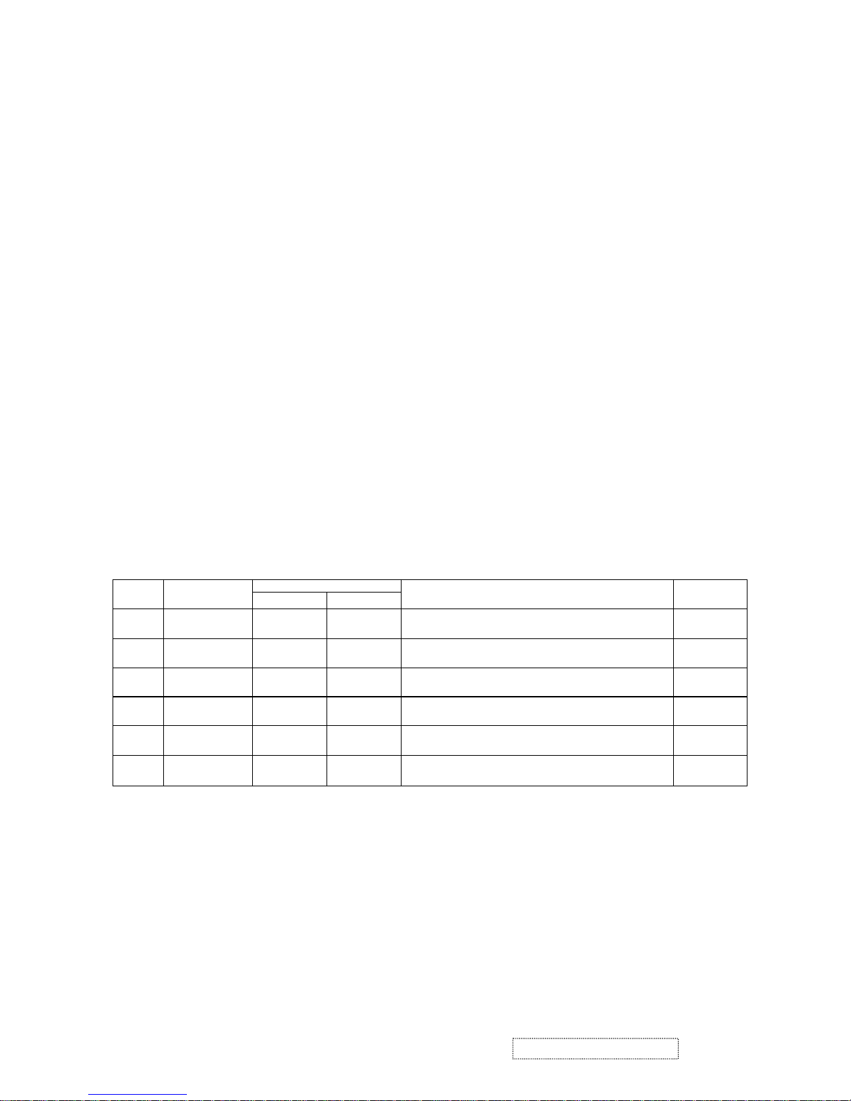
5. Handling Methods
3
ViewSonic Corporation Confidential
-
Do Not Copy VP912s/b
Only touch the metal frame of the LCD
panel or the front cover of the monitor. Do
not touch the surface of the polarizer.
If the surface of the LCD panel is pressed
by fingers, that may cause "MURA."
Take out the monitor by grasping the cushions.
If the monitor is removed by grasping the
LCD panel, that may cause "MURA."
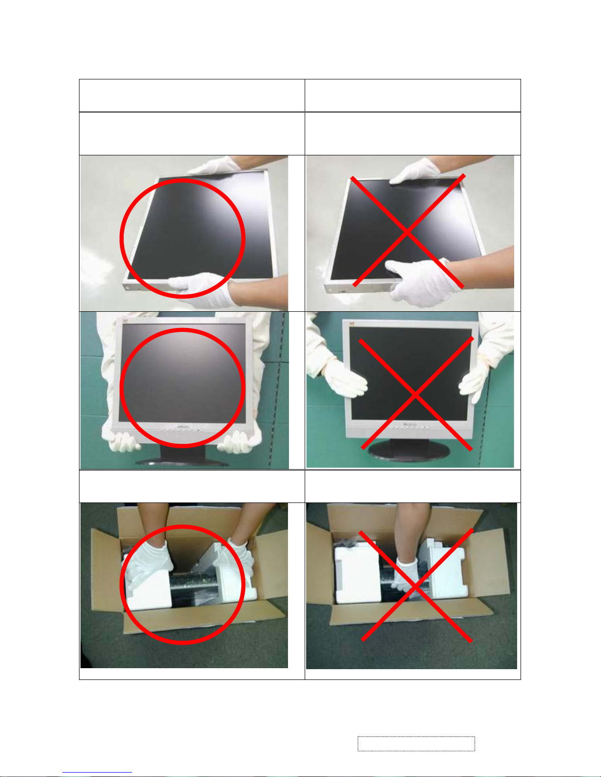
Correct Methods:
Incorrect Methods:
Page 7
4
ViewSonic Corporation Confidential
-
Do Not Copy VP912s/b
Place the monitor on a clean and soft
foam pad.
If the monitor is placed on foreign objects,
that could scratch the surface of the panel
or cause "MURA."
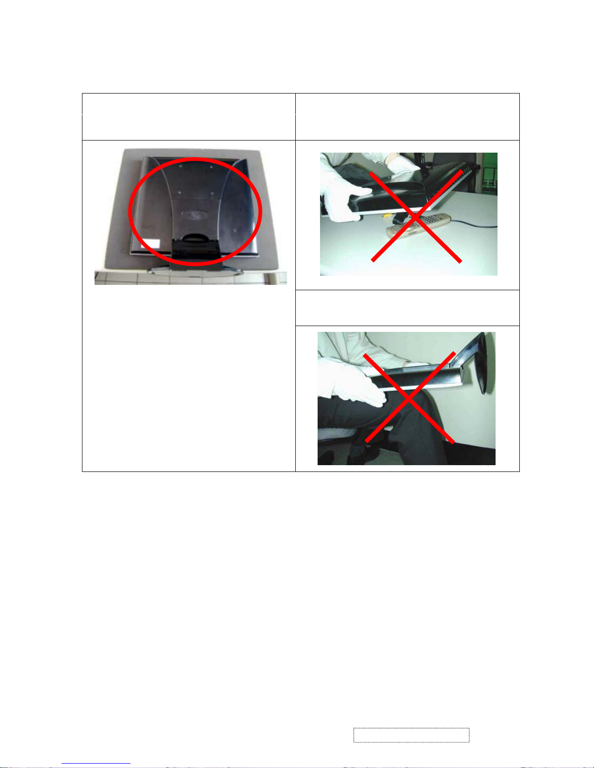
If the panel is placed facedown on the
lap, that may cause "MURA."
Page 8
1. General Requirements
General Specifications
Test Resolution & Frequency 1280x1024 @ 60Hz
Test Image Size Full Size
Contrast and Brightness Controls
Factory Default:
Contrast = 50%, Brightness = 100%
2. Signal Interface
Video Interface
Input Connector 1 (Analog 1) DB-15 (Analog)
Input Connector 2 (Analog 2) DB-15 (Analog)
Digital Input Connector DVI-I (Digital)
Default Input Connector Defaults to the first detected input
Video Cable Connector DB-15 Pin out Compliant DDC 2B
Video Signals 1. Video RGB (Analog)
Separate, Composite, and Sync on Green
2. TMDS (Digital)
Video Impedance 75 Ohms (Analog), 100 Ohms (Digital)
Exclusions Not compatible with interlaced video
3. Power
Power Supply
Internal Power Supply Primary : LSE0204A1250
2
nd
source: Tiger power TOF 5001
Input Voltage Range 90 to 264 VAC
Over Current Protection 7.0 A typical at 12.0 VDC
Power Dissipation 50 Watts (typ.)
2. Specification
5
ViewSonic Corporation Confidential
-
Do Not Copy VP912s/b
Page 9
4. Electrical Requirements
Horizontal / Vertical Frequency
Horizontal Frequency 24 – 82 KHz
Vertical Refresh Rate 50 – 85* HZ.
FOR RESOLUTION 1280 X 1024, THE
VERTICAL RFRESH RATE UP TO 75 HZ; FOR
THE REST RESOLUTIONS, THE VERTICAL
REFRESH RATE UP TO 85HZ
Maximum Pixel Clock 135 MHz
Primary Presets 1280x1024 @ 60Hz
Look up table timing
<<Analog>>
640 x 350 @ 70Hz, 31.5kHz
640 x 400 @ 60Hz, 31.5kHz
640 x 400 @ 70Hz, 31.5kHz
640 x 480 @ 50Hz, 24.7kHz
640 x 480 @ 60Hz, 31.5kHz
640 x 480 @ 67Hz, 35.0kHz
640 x 480 @ 72Hz, 37.9kHz
640 x 480 @ 75Hz, 37.5kHz
640 x 480 @ 85Hz, 43.27kHz
720 x 400 @ 70Hz, 31.5kHz
800 x 600 @ 56Hz, 35.1kHz
800 x 600 @ 60Hz, 37.9kHz
800 x 600 @ 75Hz, 46.9kHz
800 x 600 @ 72Hz, 48.1kHz
800 x 600 @ 85Hz, 53.7kHz
832 x 624 @ 75Hz, 49.7kHz
1024 x 768 @ 60Hz, 48.4kHz
1024 x 768 @ 70Hz, 56.5kHz
1024 x 768 @ 72Hz, 58.1kHz
1024 x 768 @ 75Hz, 60.0kHz
1024 x 768 @ 85Hz, 68.67kHz
1152 x 864 @ 75Hz, 67.5kHz
1152 x 870 @ 75Hz, 68.7kHz
1280 x 1024 @ 60Hz, 63.4kHz
1280 x 1024 @ 75Hz, 79.97kHz
1280x 720 @ 60Hz, 45kHz (HDTV)
<<Digital>>
640 x 350 @ 70Hz, 31.5kHz
640 x 400 @ 60Hz, 31.5kHz
640 x 400 @ 70Hz, 31.5kHz
640 x 480 @ 50Hz, 24.7kHz
640 x 480 @ 60Hz, 31.5kHz
640 x 480 @ 67Hz, 35.0kHz
640 x 480 @ 72Hz, 37.9kHz
640 x 480 @ 75Hz, 37.5kHz
640 x 480 @ 85Hz, 43.27kHz
720 x 400 @ 70Hz, 31.5kHz
800 x 600 @ 56Hz, 35.1kHz
800 x 600 @ 60Hz, 37.9kHz
800 x 600 @ 75Hz, 46.9kHz
800 x 600 @ 72Hz, 48.1kHz
800 x 600 @ 85Hz, 53.7kHz
832 x 624 @ 75Hz, 49.7kHz
1024 x 768 @ 60Hz, 48.4kHz
1024 x 768 @ 70Hz, 56.5kHz
1024 x 768 @ 72Hz, 58.1kHz
1024 x 768 @ 75Hz, 60.0kHz
1024 x 768 @ 85Hz, 68.67kHz
1152 x 864 @ 75Hz, 67.5kHz
1152 x 870 @ 75Hz, 68.7kHz
1280 x 1024 @ 60Hz, 63.4kHz
1280 x 1024 @ 75Hz, 79.97kHz
1280x 720 @ 60Hz, 45kHz (HDTV)
Changing Modes
z Maximum Mode Change Blank Time for
image stability : 3 seconds (Max), excluding
“Auto Adjust” time
z Under DOS mode (640 x 350, 720 x 400 &
640 x 400), it should recall factory setting
when execute “Auto Adjust” by “0-Touch™”
z The monitor needs to do “Auto Adjust” the
first time a new mode is detected (see section
“0-Touch™ Function Actions”)
z While running Change Mode, Auto Adjust or
Memory Recall, the image shall blank
6
ViewSonic Corporation Confidential
-
Do Not Copy VP912s/b
Page 10
5. LCD Panel
Panel Characteristics
Model number AUO M190EN04
Type TN type with LVDS interface
Active Size 376.32 (H) x 301.06 (V)
Pixel Arrangement RGB Vertical Stripe
Pixel Pitch 0.294 mm
GLASS TREATMENT Anti Glare (Hard coating 2H)
# OF BACKLIGHTS 4 CCFL edge-light (2 top / 2 bottom)
BACKLIGHT LIFE 50,000 (Typ) / 40,000 Hours (Min)
Luminance (Center) – CT = 6500K
Contrast/ Brightness = Max
400 cd/m2 (Typ after 30 minute warm up)
350 cd/m2 (Min after 30 minute warm up)
Brightness Uniformity 75% (Typ) / 70% (Min) Entire Area
Contrast Ratio 450:1 (typ), 250:1 (min)
Color Depth 16 million colors (6+2 bit)
Viewing Angle (Horizontal, CR>10) Minimum: 130º (±65º)
Typical: 135º (+70º/-65º)
Viewing Angle (Vertical, @ CR>10) Minimum: 125º (+65º/-60º)
Response Time
10%-90% @ Ta=25°C
12 ms (Tr= 3.6 ms, Tf = 8.4 ms) (typ)
21 ms (Tr= 6.3 ms, Tf = 14.7 ms) (max)
6. Mechanical
Dimensions
Width 416 mm (16.4 inch)
Height 460 mm (18.1 inch)
Depth 238 mm (9.4 inch)
Monitor Weight 7.5 kg / 16.5 lbs
Ergonomics
Tilt Up
From 0º up to ≧20º+/-2º
Tilt Down From 0º down to -3º ~ -5 º
7. Environmental
Environmental Conditions
Operating Temperature 0°C to +40°C
Storage Temperature -20°C to +60°C
Operating Relative Humidity 20% to 90% RH Non-Condensing
Storage Relative Humidity 5% to 90% RH Non-Condensing
Operating Altitude 0 to +3,000 meters
Storage Altitude 0 to +12,000 meters
7
ViewSonic Corporation Confidential
-
Do Not Copy VP912s/b
Page 11
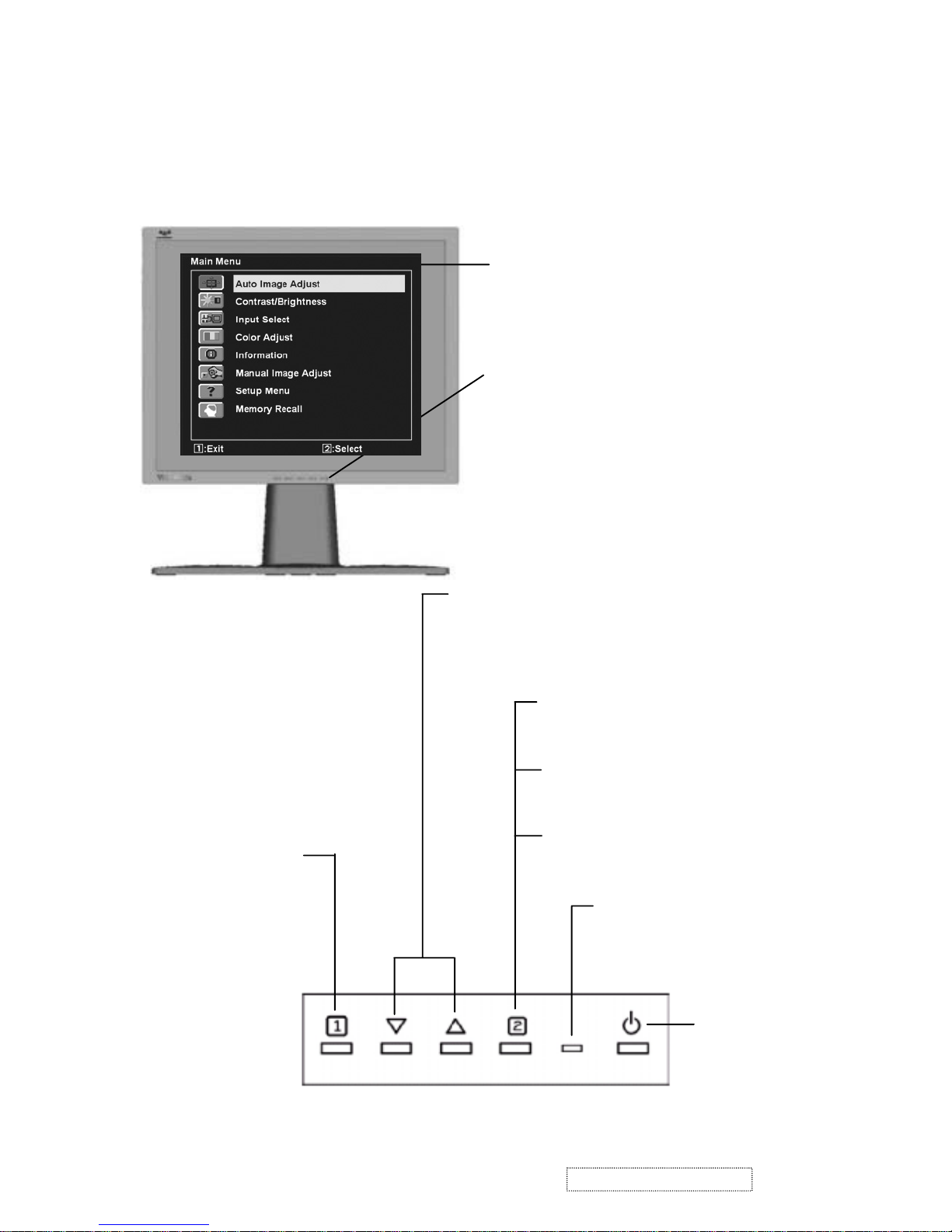
Use the buttons on the front control panel to display and adjust the OnView®
controls which display on the screen. The OnView controls are explained at the
top of the next page.
Front Control Panel
shown below in detail
Main Menu
with OnView controls
Scrolls through menu options and
adjusts the displayed control.
Also a shortcut to display the
Contrast adjustment control
screen.
Power
On/Off
Displays the control
screen for the highlighted
control.
Also toggles between two
controls on some
screens.
Also a shortcut to toggle
analog and digital connection.
Power light
Green = ON
Orange = Power
Saving
Displays the Main Menu
or exits the control screen
and saves adjustments.
3. Front Panel Function Control Description
8
ViewSonic Corporation Confidential
-
Do Not Copy VP912s/b
Page 12
Do the following to adjust the screen image:
1
To display the Main Menu, press button [1].
4
To adjust the control, press the up ▲ or down ▼ buttons.
5
To save the adjustments and exit the menu, press button [1]
twice
.
The following tips may help you optimize your display:
• Adjust your computer's graphic card so that it outputs a video signal 1280 x
1024 @ 60Hz to the LCD display. (Look for instructions on "changing the
refresh rate" in your graphic card's user guide.)
• If necessary, make small adjustments using H POSITION and V POSITION
until the screen image is completely visible
. (The black border around the
edge of the screen should barely touch the illuminated "active area" of the
LCD display.)
9
ViewSonic Corporation Confidential
-
Do Not Copy VP912s/b
NOTE: All OnView menus and adjustment screens disappear automatically
after about 30 seconds. This time period is adjustable through the Setup
menu and the OSD timeout control described on page 10.
2
To select a control to be adjusted, press ▲ or ▼ to scroll up or down in
the Main Menu.
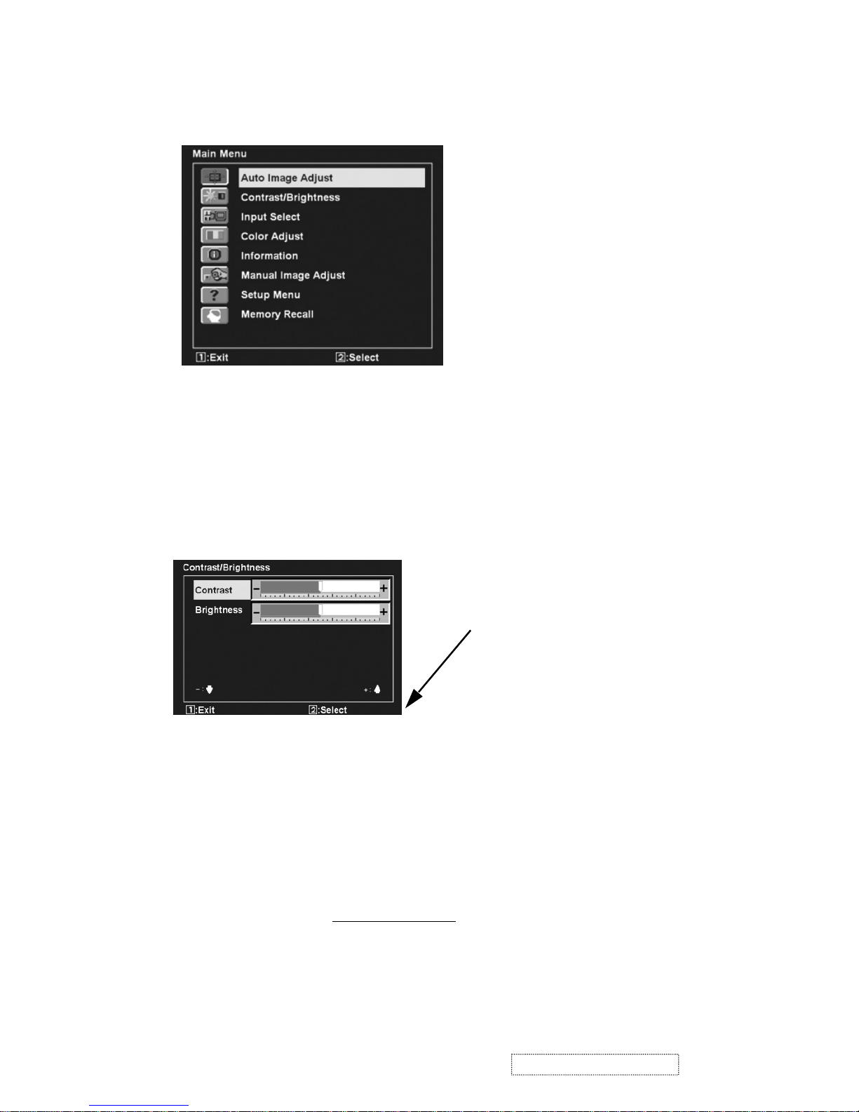
3
To select the highlighted control, press button [2]. A control screen appears
like the example shown below.
The line at the bottom
of the screen shows
the current functions
of buttons 1 and 2:
in this example, either
EXIT or select the
BRIGHTNESS
control.
Page 13
Main Menu Controls
Adjust the menu items shown below by using the up ▲ and down ▼ buttons.
Control Explanation
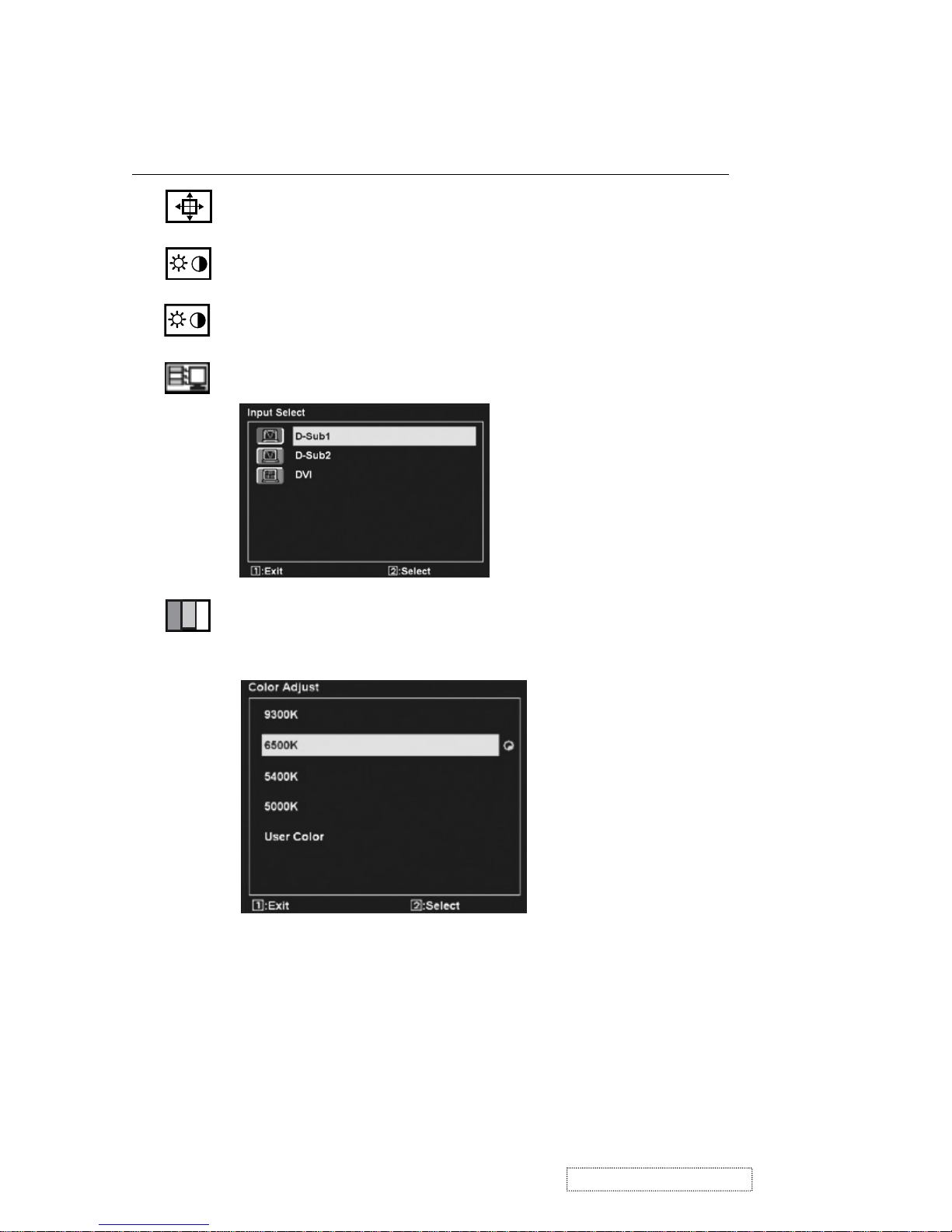
Auto Image Adjust
sizes and centers the screen image
automatically.
Contrast
adjusts the difference between the image background
(black level) and the foreground (white level).
Brightness
adjusts background black level of the screen image.
Input Select
toggles between inputs if you have more than one
computer connected to the VP912b/VP912s.
Color Adjust
provides several color adjustment modes: preset
color temperatures and
RGB
which allows you to adjust red (R),
green (G), and blue (B) separately. The factory setting for this
product is 6500K (6500 Kelvin).
9300K
— Adds blue to the screen image for cooler white (used
in most office settings with fluorescent lighting).
6500K
— Adds red to the screen image for warmer white and
richer red.
5400K
— Adds green to the screen image for a darker color.
5000K
— Adds blue and green to the screen image for a darker
color.
10
ViewSonic Corporation Confidential
-
Do Not Copy VP912s/b
Page 14
User Color
— Individual adjustments for red (R), green (G),
and blue (B)
.
1
To select color (R, G or B) press button [2].
2
To adjust selected color, press ▲ or ▼.
Important
: If you select RECALL from the Main Menu when
the product is set to a Preset Timing Mode, colors return to the
6500K factory preset.
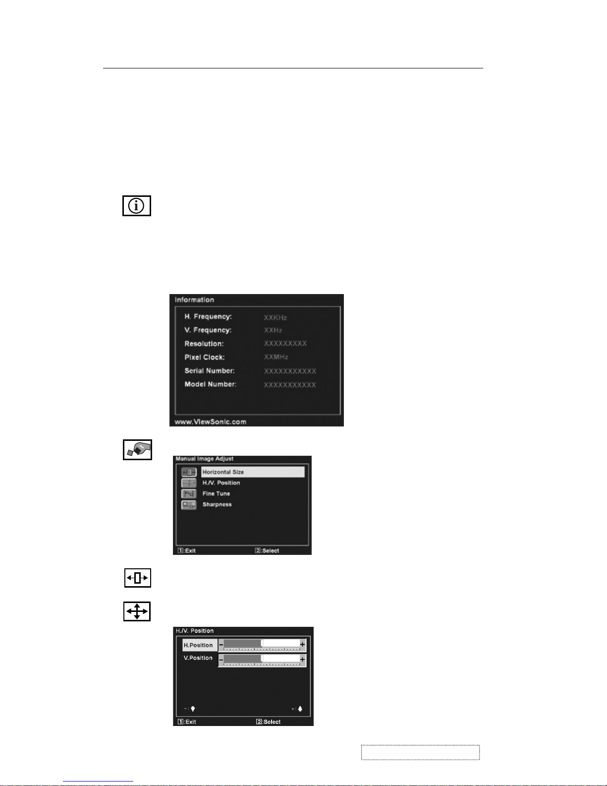
Control Explanation
Information
displays the timing mode (video signal input)
coming from the graphics card in your computer, the LCD
model number, the serial number, and the ViewSonic website
URL. See your graphic card’s user guide for instructions on
changing the resolution and refresh rate (vertical frequency).
NOTE:
VESA 1280 x 1024 @ 60Hz (recommended) means
that the resolution is 1280 x 1024 and the refresh rate is 60
Hertz.
Manual Image Adjust Sub-menu
H. Size (Horizontal Size)
adjusts the width of the screen image.
H./V. Position (Horizontal/Vertical Position)
moves the screen
image left or right and up or down.
11
ViewSonic Corporation Confidential
-
Do Not Copy VP912s/b
Page 15
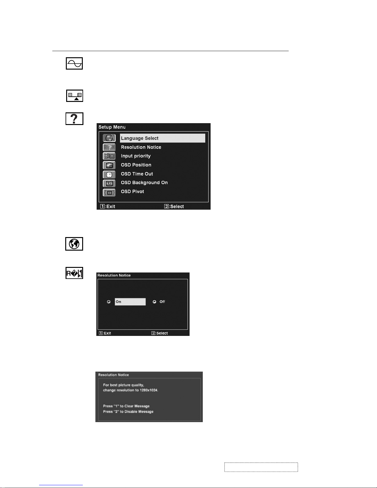
Fine Tune sharpens the focus by aligning the text and graphics with
display pixels.
NOTE: Try Auto Image Adjust first.
Sharpness
adjusts the clarity and focus of the screen image.
Setup menu displays the menu shown below:
Language Selec t
allows the user to choose the language used in the menus
and control screens.
Control Explanation
Resolution Notice
allows you to enable or disable this notice.
If you enable the Resolution Notice shown above and your
computer is set at a resolution other than 1280 x 1024, the
following screen appears.
12
ViewSonic Corporation Confidential
-
Do Not Copy VP912s/b
Page 16
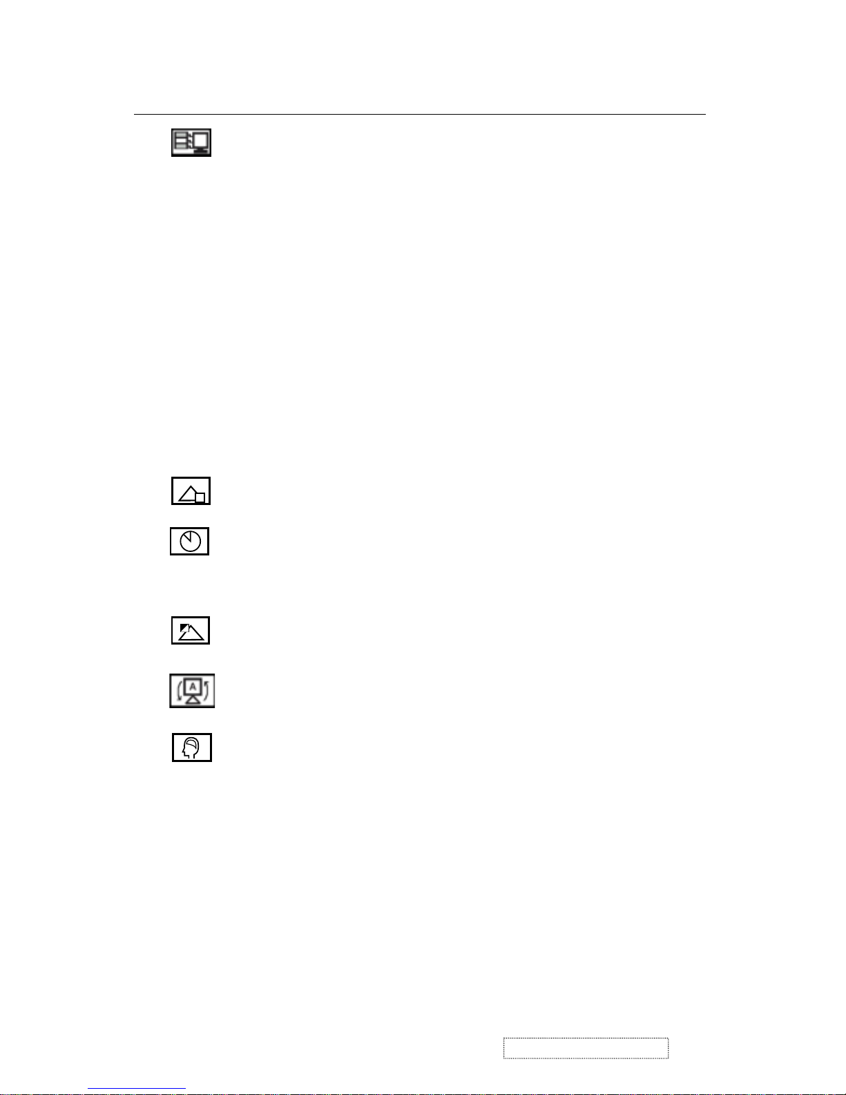
OSD Position
allows the user to move the on-screen display menus
and control screens.
OSD Timeout
sets the length of time the on-screen display
screen is displayed. For example, with a “30 second” setting, if a
control is not pushed within 30 seconds, the display screen
disappears.
Control Explanation
Memory Recall
returns the adjustments back to factory settings
if the display is operating in a factory Preset Timing Mode listed
in the Specifications of this manual.
OSD Pivot
This function is used to rotate the OSD menu,
when the display is changed from Landscape to Portrait mode.
OSD Background
On/Off
allows the user to turn the On-Screen display
background on or off.
13
ViewSonic Corporation Confidential
-
Do Not Copy VP912s/b
Input Priority If multiple computers will be connected to the display,
this function can be used to select which computer has priority.
The display will do a one time detection for available inputs when first
powered on, and choose one depending on the selected input priority.
For example: If the Input Priority setting is D-SUB1=>D-SUB2=>DVI,
then the first priority will be given to D-SUB1 when the display turns
on. If there is no video signal on D-SUB1, then the next priority will be
given to D-SUB-2, etc… In the case when only one signal is present at
the three inputs, then the display will automatically detect and display
that signal.
The Input Priority setting can also be disabled. In this case, the input will
return to the last active setting when the display is first turned on. The
user will need to set all the port settings manually under this condition.
Inputs can be switched quickly by pressing the "Up" arrow
button on the front control panel.
Page 17
Hot Keys for Function Controls
Buttons: Functions:
[Up] or [Down] arrows To immediately activate Contrast menu. It should
be change to Brightness OSD by push button [2]
[Up] + [Down] arrows Recall Contrast or Brightness while in the Contrast
or Brightness adjustment, or recall both of Contrast
and Brightness when the OSD is not on.
[1] + [2] Toggle 720x400 and 640x400 mode when input
720x400 or 640x400 mode.
[1] + [Power On] with signal Factory Mode
[1] + [Up] + [Down] White Balance: shall enter Factory Mode first.
White Balance should set the screen on the pure
black and white pattern with 1280*1024@60Hz
resolution.
[1] + [Down] (hold for 10 seconds) Power Lock (Unlock). User won’t be able to turn off
the monitor.
[1] + [Up] (hold for 10 seconds) OSD Lock (Unlock). It will lock all functions.
[Up] + [Down] + [Power On] with signal
(Hold for 3 seconds. Release “Power” button first
and then “Up” & ”Down” buttons.)
All Mode Reset. It will erase all end users’ settings
and restore the factory defaults.
[Up] + [Down] + [Power On]
Without signal
(Hold for 3 seconds. Release “Power” button first
and then “Up” & ”Down” buttons.)
Burn in Mode. After entering Burn in Mode, press
[1] button, you can find the information about this
monitor.
Remark: All the shortcut functions are only available while OSD is off.
14
ViewSonic Corporation Confidential
-
Do Not Copy VP912s/b
Page 18
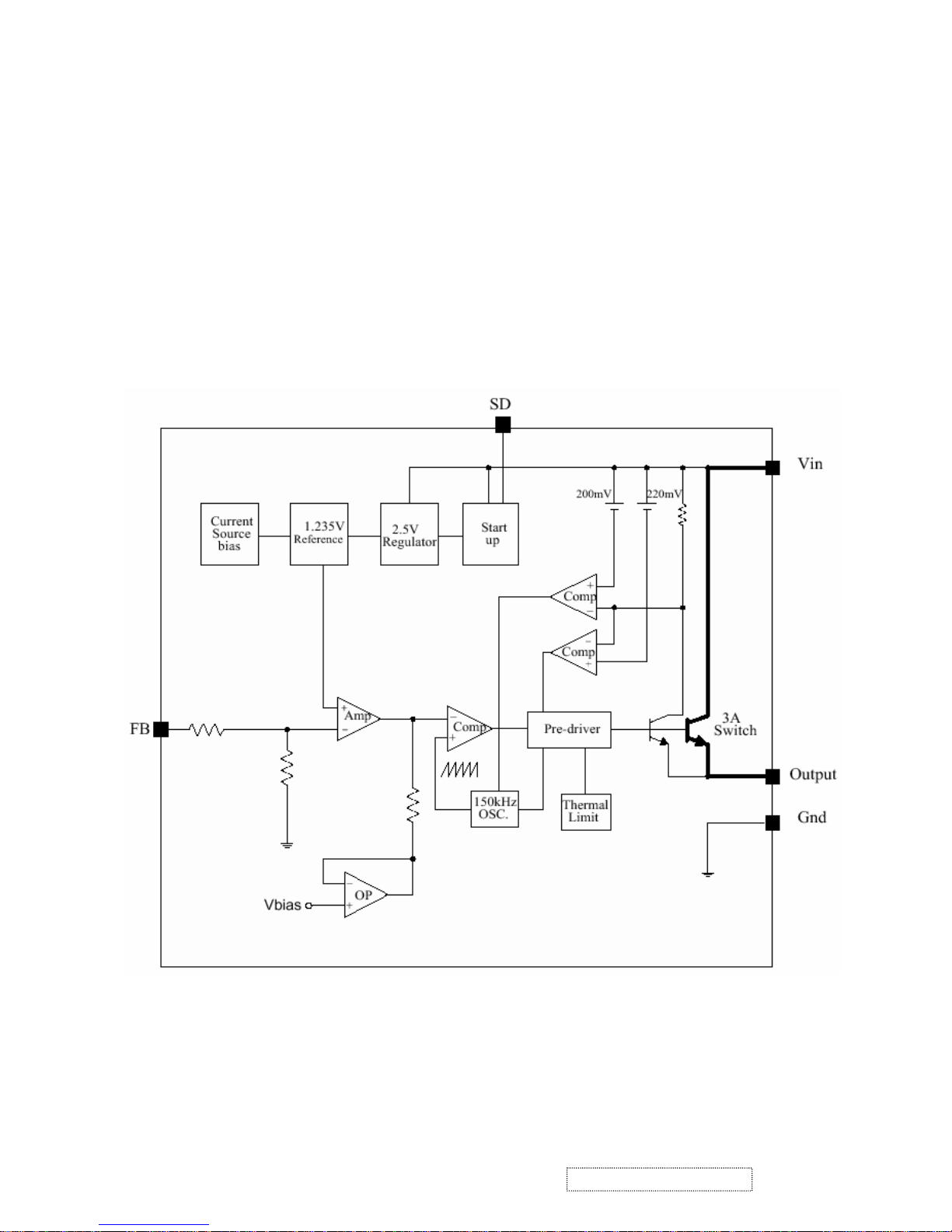
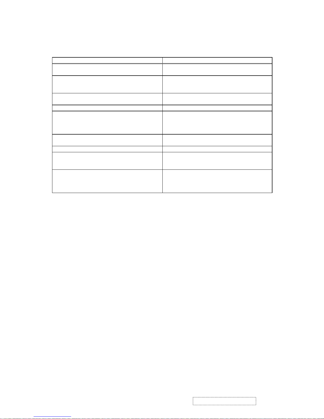
1. Power supply (DC/DC Converter)
The AP1501 is monolithic IC designed for M/B DC/DC converter, and owns the ability of driving a 3A load without
any additional transistor component.
The AP1501 operates at a switching frequency of 150KHz and thus allows smaller-sized filter components than what
would be needed with lower frequency switch regulator.
4. Circuit Description
15
ViewSonic Corporation Confidential
-
Do Not Copy VP912s/b
Page 19
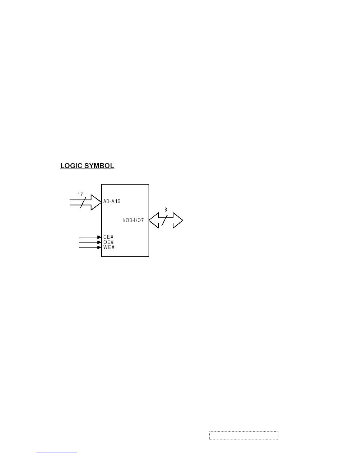
2. Flash Memory
The Pm39LV010R is a 1 Megabit, 3.3 Volt-only Flash Memory organized as 131,072 bytes of 8 bits each.
This device is designed to use a 3.0 Volt to 3.6 Volt power supply to perform in-system programming.
The 1 Megabit memory array is divided into thirty-two uniform blocks of 4 Kbytes each for data and/or code storage.
The block architecture allows users to flexibly make chip erase or block erase operation. The block erase feature
a
llows a particular block to be erased and reprogrammed without affecting the data in other blocks. After the
device performs chip erase or block erase operation, it can be reprogrammed on a byte-by-byte basis.
3. GM5120
The gm5110/20 is a graphic processing IC for Liquid Crystal Display (LCD) monitors at XGA/SXGA resolution.
It provides all key IC functions required for the highest quality LCD monitors. On-chip functions include a
high-speed triple-ADC and PLL, Ultra-Reliable DVI
TM receiver
, a high quality zoom and shrink scaling engine,
an on-screen display (OSD) controller, digital color controls and an on-chip microcontroller (OCM). With this level
of integration, he gm5110/20 devices simplify and reduce the cost of LCD monitors while maintaining a high-degree
of flexibility and quality.
16
ViewSonic Corporation Confidential
-
Do Not Copy VP912s/b
Page 20

gm5110/5120 System Design Example
4. LVDS (THC63LVDM8 3A)
The THC63LVDM83A transmitter converts 28 bits of CMOS/TTL data into LVDS (Low Voltage Differential
Signaling) data stream. A phase-locked transmit clock is transmitted in parallel with the data streams over a fifth
LVDS link. The HC63LVDM83A can be programmed for rising edge or falling edge clocks through a dedicated pin.
The THC63LVDF84A receiver converts the LVDS data streams back into 28 bits of CMOS/TTL data with falling
edge clock. At a transmit clock frequency of 85MHz, 24 bits of RGB data and 4 bits of LCD timing and control data
(HSYNC, VSYNC, CNTL1, CNTL2) are transmitted at a rate of 595 Mbps per LVDS data channel.
17
ViewSonic Corporation Confidential
-
Do Not Copy VP912s/b
Page 21
1. Function Test
1.1 Product
- 19” LCD Monitor
1.2 Test Equipment
- Color Video Signal & Pattern (or PC with SXGA resolution)
1.3 Test Condition
Before function test and alignment, each LCD Monitor should be run-in and warmed up for at least 30
minutes with the following conditions:
(a) In room temperature,
(b) With full-white screen, RGB, and Black
(c) With cycled display modes,
640*480 (H=43.27KHz, V=85Hz)
800*600 (H=53.7KHz, V=85Hz)
1024*768 (H=68.67KHz, V=85Hz)
1280*1024 (H=79.97KHz, V=75Hz)
1.4 Test Display Modes & Pattern
1.4.1 Compatible Modes
Analog Digital
1. 640 x 350 @ 70Hz, 31.5kHz
2. 640 x 400 @ 60Hz, 31.5kHz
3. 640 x 400 @ 70Hz, 31.5kHz
4. 640 x 480 @ 50Hz, 24.7kHz
5. 640 x 480 @ 60Hz, 31.5kHz
6. 640 x 480 @ 67Hz, 35.0kHz
7. 640 x 480 @ 72Hz, 37.9kHz
8. 640 x 480 @ 75Hz, 37.5kHz
9. 640 x 480 @ 85Hz, 43.27kHz
10. 720 x 400 @ 70Hz, 31.5kHz
11. 800 x 600 @ 56Hz, 35.1kHz
12. 800 x 600 @ 60Hz, 37.9kHz
13. 800 x 600 @ 75Hz, 46.9kHz
14. 800 x 600 @ 72Hz, 48.1kHz
15. 800 x 600 @ 85Hz, 53.7kHz
640 x 350 @ 70Hz, 31.5kHz
640 x 400 @ 60Hz, 31.5kHz
640 x 400 @ 70Hz, 31.5kHz
640 x 480 @ 50Hz, 24.7kHz
640 x 480 @ 60Hz, 31.5kHz
640 x 480 @ 67Hz, 35.0kHz
640 x 480 @ 72Hz, 37.9kHz
640 x 480 @ 75Hz, 37.5kHz
640 x 480 @ 85Hz, 43.27kHz
720 x 400 @ 70Hz, 31.5kHz
800 x 600 @ 56Hz, 35.1kHz
800 x 600 @ 60Hz, 37.9kHz
800 x 600 @ 75Hz, 46.9kHz
800 x 600 @ 72Hz, 48.1kHz
800 x 600 @ 85Hz, 53.7kHz
5. Adjustment Procedure
18
ViewSonic Corporation Confidential
-
Do Not Copy VP912s/b
Page 22
16. 832 x 624 @ 75Hz, 49.7kHz
17. 1024 x 768 @ 60Hz, 48.4kHz
18. 1024 x 768 @ 70Hz, 56.5kHz
19. 1024 x 768 @ 72Hz, 58.1kHz
20. 1024 x 768 @ 75Hz, 60.0kHz
21. 1024 x 768 @ 85Hz, 68.67kHz
22. 1152 x 864 @ 75Hz, 67.5kHz
23. 1152 x 870 @ 75Hz, 68.7kHz
24. 1280 x 1024 @ 60Hz, 63.4kHz
25. 1280 x 1024 @ 75Hz, 79.97kHz
26. 1280x 720 @ 60Hz, 45kHz (HDTV)
832 x 624 @ 75Hz, 49.7kHz
1024 x 768 @ 60Hz, 48.4kHz
1024 x 768 @ 70Hz, 56.5kHz
1024 x 768 @ 72Hz, 58.1kHz
1024 x 768 @ 75Hz, 60.0kHz
1024 x 768 @ 85Hz, 68.67kHz
1152 x 864 @ 75Hz, 67.5kHz
1152 x 870 @ 75Hz, 68.7kHz
1280 x 1024 @ 60Hz, 63.4kHz
1280 x 1024 @ 75Hz, 79.97kHz
1280x 720 @ 60Hz, 45kHz (HDTV)
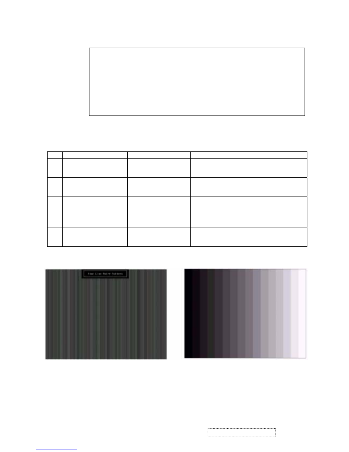
1.4.2 Function Test Display Pattern
Item Test Content Pattern Specification Remark
1 Frequency & Tracking Fine Line Moire Eliminate visual wavy noise. Figure 1
2 Contrast/Brightness 16 Gray Scale 16 gray levels should be
distinguishable.
Figure 2
3 Boundary Horizontal & Vertical
Thickness
Horizontal and Vertical position of
video should be adjustable to be
within the screen frame.
Figure 3
4 RGB Color Performance RGB Color Intensities Contrast of each R, G, B, color
should be normal.
Figure 4, 5, 6
5 Screen Uniformity & Flicker Full White Should be compliant with the spec. Figure 7
6 Dead Pixel/Line White Screen & Dark
Screen
The numbers of dead pixels should
be compliant with the spec.
Figure 7, 8
7 White Balance White & Black Pattern The screen must have the pure
white and black pattern, no other
color.
Figure 9
Fine Line Morie Pattern (Figure1) Gray Scale Pattern (Figure2)
19
ViewSonic Corporation Confidential
-
Do Not Copy VP912s/b
Page 23
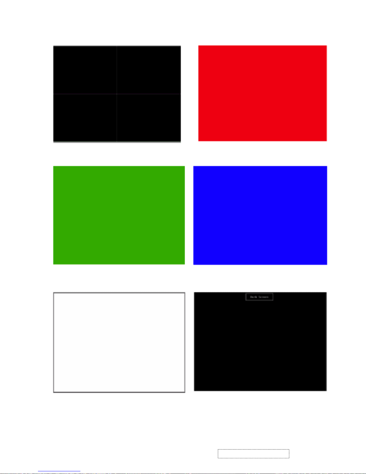
Horizontal & Vertical Thickness Pattern (Figure 3) R. Color Pattern (Figure 4)
G. Color Pattern (Figure5) B. Color Pattern (Figure 6)
Full White Patter (Figure 7) Dark Screen Pattern (Figure 8)
20
ViewSonic Corporation Confidential
-
Do Not Copy VP912s/b
Page 24

Black-White Pattern (Figure 9)
1.5 Function Test and Alignment Procedure
1.5.1 All Modes Reset
You should do “All Mode Reset” (Refer to Chapter III-3. Hot Keys for Function Controls) first. This action
will allow you to erase all end-user’s settings and restore the factory defaults.
1.5.2 Auto Image Adjust
Please select and enter “Auto Image Adjust” function on Main Menu to see if it is workable.
The "Auto Image Adjust" function is aimed to offer a better screen quality by built-in ASIC.
For optimum screen quality, the user has to adjust each function manually.
1.5.3 Firmware
Test Pattern: Burn In Mode (Refer to Chapter III-3. Hot Keys for Function Controls)
- Make sure the F/W is the latest version.
1.5.4 DDC
Test Pattern: EDID program
- Make sure it can pass test program.
1.5.5 Fine Tune and Sharpness
Test Signal: 1280*1024@60Hz
Test Pattern: Line Moire Pattern
- Check and see if the image has noise and focus performs well. Eliminate visual line bar.
- If not, readjust by the following steps:
(a) Select and enter “Fine Tune” function on “Manual Image Adjust” to adjust the image to eliminate
visual wavy noise.
(b) Then, select and enter “Sharpness” function to adjust the clarity and focus of the screen image.
21
ViewSonic Corporation Confidential
-
Do Not Copy VP912s/b
Page 25

1.5.6 Boundary
Test Signal: 1280*1024@60Hz
Test Pattern: Horizontal & Vertical Line Thickness Pattern
- Check and see if the image boundary is within the screen frame.
- If not, readjust by the following steps:
(a) Select and enter “Manual Image Adjust” function on OSD Main Menu.
(b) Then, select and enter “Horizontal Size” or “Horizontal/Vertical Position” function to adjust the
video boundary to be full scanned and within screen frame.
1.5.7 White Balance (Auto Gain) (Refer to Chapter III-3. Hot Keys for Function Controls)
Test Signal: 1280*1024@60Hz
Test Pattern: White and Black Pattern
1.5.8 R, G, B, Colors Contrast
Test Signal: 1280*1024@60Hz
Test Pattern: R, G, B, Color Intensities Pattern and 16 Gray Scale Pattern
- Check and see if each color is normal and distinguishable.
- If not, please return the unit to repair area.
1.5.9 Screen Uniformity and Flicker
Test Signal: 1280*1024@60Hz
Test Pattern: Full White Pattern
- Check and see if it is in normal condition.
1.5.10 Dead Pixel and Line
Test Signal: 1280*1024@60Hz
Test Pattern: Dark and White Screen Pattern
- Check and see if there are dead pixels on LCD panel with shadow gauge and filter film.
- The total numbers and distance of dead pixels should be compliant with the spec.
1.5.11 Mura
Test Pattern: White, RGB, Black, & Grey
Test Tool: 8% ND Filter
- Use 8% ND Filter to check if any Mura on the screen.
22
ViewSonic Corporation Confidential
-
Do Not Copy VP912s/b
Page 26

1.5.12 Check for Secondary Display Modes
Test Signal:
Analog: 640 x 350 @ 70Hz, 31.5kHz ; 640 x 400 @ 60Hz, 31.5kHz ; 640 x 400 @ 70Hz, 31.5kHz
640 x 480 @ 50Hz, 24.7kHz ; 640 x 480 @ 60Hz, 31.5kHz ; 640 x 480 @ 67Hz, 35.0kHz
640 x 480 @ 72Hz, 37.9kHz ; 640 x 480 @ 75Hz, 37.5kHz ; 640 x 480 @ 85Hz, 43.27kHz
720 x 400 @ 70Hz, 31.5kHz ; 800 x 600 @ 56Hz, 35.1kHz ; 800 x 600 @ 60Hz, 37.9kHz
800 x 600 @ 75Hz, 46.9kHz ; 800 x 600 @ 72Hz, 48.1kHz ; 800 x 600 @ 85Hz, 53.7kHz
832 x 624 @ 75Hz, 49.7kHz ; 1024 x 768 @ 60Hz, 48.4kHz ; 1024 x 768 @ 70Hz, 56.5kHz
1024 x 768 @ 72Hz, 58.1kHz ; 1024 x 768 @ 75Hz, 60.0kHz ; 1024 x 768 @ 85Hz, 68.67kHz
1152 x 864 @ 75Hz, 67.5kHz ; 1152 x 870 @ 75Hz, 68.7kHz ; 1280 x 1024 @ 75Hz, 79.97kHz ;
1280x 720 @ 60Hz, 45kHz (HDTV)
Digital: 640 x 350 @ 70Hz, 31.5kHz ; 640 x 400 @ 60Hz, 31.5kHz ; 640 x 400 @ 70Hz, 31.5kHz
640 x 480 @ 50Hz, 24.7kHz ; 640 x 480 @ 60Hz, 31.5kHz ; 640 x 480 @ 67Hz, 35.0kHz
640 x 480 @ 72Hz, 37.9kHz ; 640 x 480 @ 75Hz, 37.5kHz ; 640 x 480 @ 85Hz, 43.27kHz
720 x 400 @ 70Hz, 31.5kHz ; 800 x 600 @ 56Hz, 35.1kHz ; 800 x 600 @ 60Hz, 37.9kHz
800 x 600 @ 75Hz, 46.9kHz ; 800 x 600 @ 72Hz, 48.1kHz ; 800 x 600 @ 85Hz, 53.7kHz
832 x 624 @ 75Hz, 49.7kHz ; 1024 x 768 @ 60Hz, 48.4kHz ; 1024 x 768 @ 70Hz, 56.5kHz
1024 x 768 @ 72Hz, 58.1kHz ; 1024 x 768 @ 75Hz, 60.0kHz ; 1024 x 768 @ 85Hz, 68.67kHz
1152 x 864 @ 75Hz, 67.5kHz ;1152 x 870 @ 75Hz, 68.7kHz ; 1280 x 1024 @ 75Hz, 79.97kHz ;
1280x 720 @ 60Hz, 45kHz (HDTV)
- Normally when the primary mode 1280*1024@60Hz is well adjusted and compliant with the specification,
the secondary display modes will be great possible to be compliant with the spec. But we still have to check
with the general test pattern to make sure every secondary is compliant with the specification.
1.5.13 All Modes Reset
After final QC step, we have to erase all saved changes again and restore the factory defaults. You should do
"All Mode Reset" again.
1.5.14 Power Off Monitor
Turn off the monitor by pressing “Power” button, and turn off the power switch on the back of the monitor.
23
ViewSonic Corporation Confidential
-
Do Not Copy VP912s/b
Page 27

2. Firmware Upgrade Procedure
When you receive the returned monitor, please check whether the firmware version is the latest. If not,
please do the following procedures to upgrade it to the latest version.
2.1 Equipment Needed
- VP912 Monitor
- Fixture for Firmware Upgrade
- Power Adapter (P/N: 47.58201.001) *1 for Fixture (12 VDC)
- VGA Cable (P/N: 42.59901.003) *1(Pin 4, 11 should be connected to GND)
- PC (Personal Computer) with printer port. (OS: Window 98/ME/2000)
- Printer Cable (P/N: 42.59906.001) *1
- Firmware Upgrade Program
- One additional monitor for checking the program execution
PC
VP912
Fixture
Power Adapter for Fixture
(P/N: 47.58201.001)
Printer Cable
(P/N: 42.59906.001)
VGA Cable
(P/N: 42.59901.003)
24
ViewSonic Corporation Confidential
-
Do Not Copy VP912s/b
Printer Port
Page 28
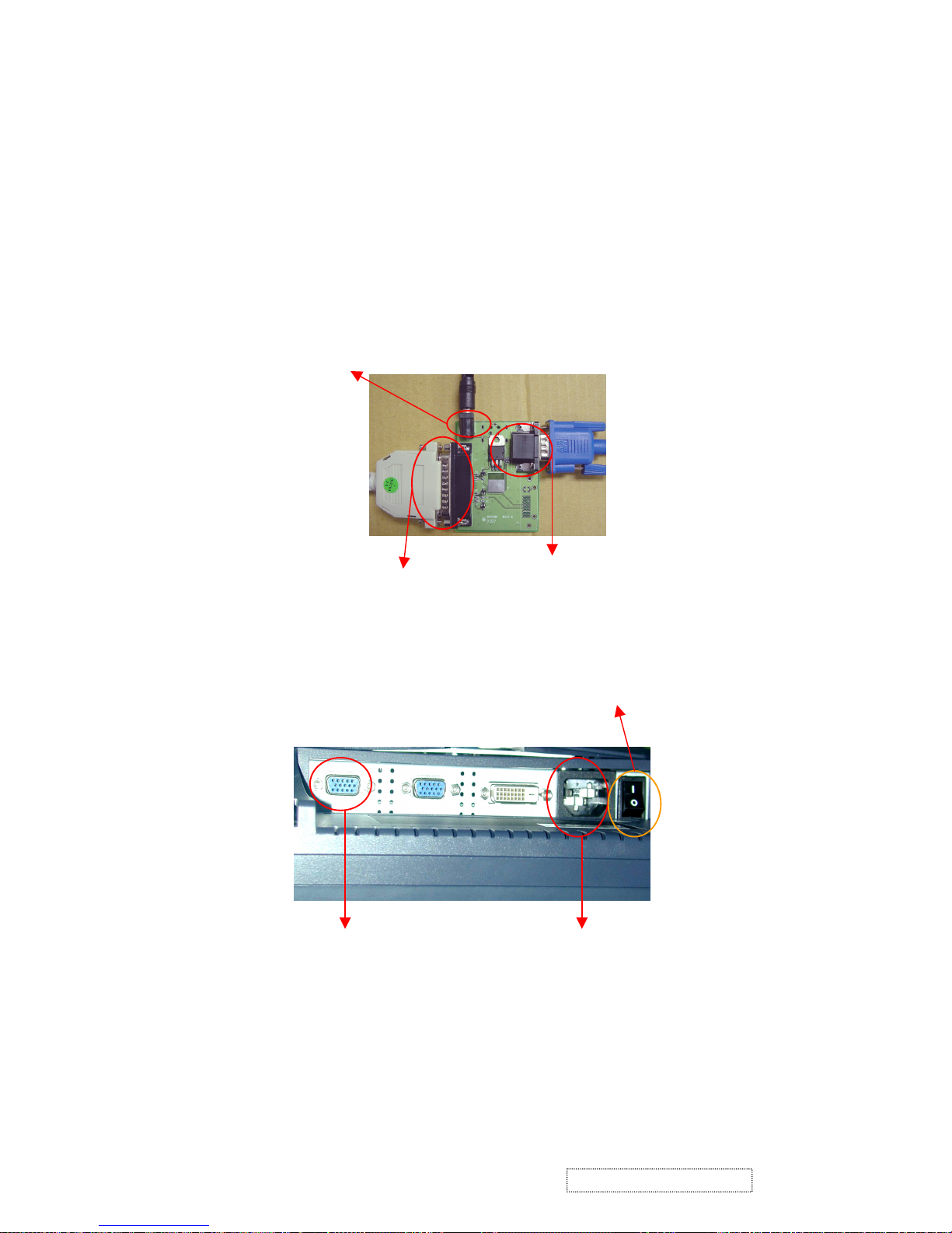
2.2 Setup Procedure
1. Connect P2 of Fixture with printer port of PC by Printer Cable.
2. Connect P1 of Fixture with VP912 Monitor by VGA Cable.
3. Plug Power Adapter to Fixture.
4. Connect Power Cord to VP912 Monitor, and turn on the Power Switch.
5. Connect PC to the additional monitor.
25
ViewSonic Corporation Confidential
-
Do Not Copy VP912s/b
P1: to VGA Cable
P2: to Printer Cable
JP1: to Power Adapter
Connect to Power Cord
Switch on Power Switch
Connect to VGA Cable
Page 29

6. Install GProbe Program by selecting and clicking Gprobe icon. Press “Yes” or “Next” buttons until the installation is
complete.
26
ViewSonic Corporation Confidential
-
Do Not Copy VP912s/b
Page 30

27
ViewSonic Corporation Confidential
-
Do Not Copy VP912s/b
Page 31

28
ViewSonic Corporation Confidential
-
Do Not Copy VP912s/b
Page 32

29
ViewSonic Corporation Confidential
-
Do Not Copy VP912s/b
Page 33

2.3 Firmware Upgrade Procedure
1. Save these three files <bdisp.txt>, <p204_205.bin> and <vp912_AU_V2_001_04611.bin> in the computer.
30
ViewSonic Corporation Confidential
-
Do Not Copy VP912s/b
2. Open <bdisp.txt> file.
Key in the path where you save the driver <p204_205.bin> and firmware <vp912_AU_V2_001_040611.bin>.
Page 34

31
ViewSonic Corporation Confidential
-
Do Not Copy VP912s/b
3. Execute Gprobe program.
4. Click Connection Setup icon. Select Protocol: DDC 2Bi3, Port: Printer1 (0x378), Speed: 70000.
Page 35

5. Link test: Key in “0” and then press “Enter”. It will show “0x00=0xD2” (If the screen shows “Error
Message”, please check your Hardware set up procedure is correct or not.
32
ViewSonic Corporation Confidential
-
Do Not Copy VP912s/b
6. Key in “batch c:\VP912\bdisp.txt” after “Probe :>”, and then press “Enter” key to begin programming
automatically.
The path is where you save <bdisp.txt> file
Page 36

33
ViewSonic Corporation Confidential
-
Do Not Copy VP912s/b
7. The successful picture is as follows:
8. Turn off the power switch of VP912, and turn it on again. Then enter “Burn In Mode”, and Serial Number will
appear. Check if the version of BIOS is correct.
Power Switch
Page 37

Troubleshooting:
1. If the firmware upgrade fails at the last step, don’t unplug the power cord of the monitor. Just try the upgrade
procedure again.
(a) If there is error to execute the command at or before line10 in the “bdisp.txt” batch file (for instance, the
message “Error executing batch file at line 4” shows up in the Gprobe program (see the following picture)),
please try to upgrade the firmware again.
Test failed.
Test failed.
Test failed.
Test failed.
Test failed.
Test failed.
Error executing batch file at line 4.
Execution time: 5.72s
GProbe:>
(b) If there is error to execute the command at or after line11 in the “bdisp.txt” batch file, please copy the error
line of the “bdisp.txt” batch file to “Gprobe:>” in the Gprobe program, and then press “Enter.” For example,
there is “Error executing batch file at line 16” (see the following picture). Then you have to copy line 16
“FLASHWRITE C:\VP912b\VP912_AU_V2_001_040611.bin” in the “bdisp.txt” file to “Gprobe:>” in the
Gprobe program, and then press “Enter” (see the picture next page).
34
ViewSonic Corporation Confidential
-
Do Not Copy VP912s/b
Page 38

Test passed.
Test passed.
Test passed.
Erasing FLASH... Done.
Writing FLASH...
Writing FLASH... FAILED.
Error executing batch file at line 16.
Execution time: 9.61s
GProbe:>
Line 16
Line 16
35
ViewSonic Corporation Confidential
-
Do Not Copy VP912s/b
Page 39

Copy the error line of the
“bdisp.txt” batch file to
“Gprobe:>”
2. If the firmware upgrade still fails, reboot the PC, or simply use another PC to upgrade.
3. If the above procedures don’t work, unplug and re-plug the power cord of VP912. Then try to upgrade the
firmware again if VP912 can be powered on. If VP912 cannot be turned on, that means the flash memory of
the main board is out of work. You then have to replace the main board.
3. DDC Key In Procedure
Note:
1. Every time after replacing the main board, you have to do the DDC key in.
2. If you find the DDC does not conform to the monitor, you have to do the DDC key in.
3.1 Equipment Needed
- VP912 Series Monitor
- Fixture (V3) for DDC Key in (JP3 must be closed)
- RS232 Cable (P/N: 42.55907.001) *1
- VGA Cable (P/N: 42.59901.008) *2
- DVI-DVI Cable *1
36
ViewSonic Corporation Confidential
-
Do Not Copy VP912s/b
Page 40

- PC (Personal Computer)
- Power Adapter (P/N: 47.56001.402) *1 for Fixture (12 VDC)
- DDC Key In Program
- One additional monitor for checking the program execution
COM1:
to
RS232
Cable
JP3 must be closed
V3 Fixture
PC VP912
Power Adapter for Fixture
(P/N: 47.56001.402)
RS-232 Cable
(P/N: 42.55907.001)
DVI-DVI Cable
Barcode Reader
VGA Cable (P/N: 42.59901.008)
37
ViewSonic Corporation Confidential
-
Do Not Copy VP912s/b
Page 41

3.2 Setup Procedure
3.2.1 Connect P2 of Fixture with VGA port of VP912 by VGA Cable.
3.2.2 Connect P3 of Fixture with DVI port of VP912 by DVI-DVI Cable.
3.2.3 Connect P1 of Fixture with COM1 of PC by RS-232 Cable.
3.2.4 Plug Power Adapter to Fixture(JP1).
3.2.5 Connect Power Cord to VP912 Monitor.
3.2.6 Connect PC to the additional monitor.
38
ViewSonic Corporation Confidential
-
Do Not Copy VP912s/b
JP1: to Power
Adapter
P1: to RS232 Cable
P2:&P4: to VGA Cable
P3: to DVI-DVI Cable
JP3 must be closed
Turn on Power Switch
Connect to Power Cord DVI PortVGA Port
Page 42

3.3 DDC Key In Procedure
2. Select and execute DDC Key In program.
3. Type “W” to enter the writing mode.
39
ViewSonic Corporation Confidential
-
Do Not Copy VP912s/b
1. Press “1” and “Power” buttons simultaneously to enter Factory Mode.
Note: The Method to check if Factory Mode is enabled: Press “1” and “Up” buttons simultaneously,
if the message of “DMT XXX” appears, that means Factory Mode is enabled.
Page 43

4. Key in the serial number and press “Enter”key.
Notice: The English of the serial number should be capital letters.
5. The successful picture is as follows. “The checksum values will appear after DDC is upgraded successfully in both VGA
and DFP (DVI) modes.”
40
ViewSonic Corporation Confidential
-
Do Not Copy VP912s/b
Page 44

6. Press “〜” button (“Shift”+”
、
”) to check DDC CheckSum is correct or not.
7. Enter “Burn In Mode.” Turn off the power switch of the rear cover of VP912, and turn it on again. Check if the
serial number is correct.
41
ViewSonic Corporation Confidential
-
Do Not Copy VP912s/b
Page 45

This chapter describes some primary methods of repairing and maintaining this product,
and is intended for technicians and others who have a background in electronics.
1. Equipment Needed
- VP912 Monitor
- Philips Screw Driver #101 and #107
- Electronic Hex Nut M5 mm
- PC (Personal Computer) with SXGA resolution and sound card or a Pattern Generator
2.Main Procedure
Note: Before troubleshooting, first execute "All Mode Reset" to restore the monitor's
settings to the factory defaults.
Power-on
Start
Power LCD ok ?
A. Power circuit
Troubleshooting
No
B. Performance
Troubleshooting
C. Function
Troubleshooting
No
Ye s
No
Is function adjustment OK ?
Ye s
Ye s
Is display performance ok?
End
6. Troubleshooting Flow Chart
42
ViewSonic Corporation Confidential
-
Do Not Copy VP912s/b
Page 46

2.1 A. Power Circuit Troubleshooting
2.2 B. Performance Troubleshooting
Change Power
Board
Start
No
Change Main Board
Ye s
Yes
End
1
Is screen white?
Yes
Replug or Change
FPC Cable
Ye s
Is screen black?
No
Change
Main Board
Abnormal Color ?
Start
Change
Inverter Board
No
Change
LCD Panel
Yes
Yes
Ye s
No
No
Change
Main Board
No
Change
LCD Panel
Ye s
Ye s
No
Yes
Ye s
Change
Main Board
No
Change
LCD Panel
Ye s
Ye s
No
43
ViewSonic Corporation Confidential
-
Do Not Copy VP912s/b
Page 47

Is screen flickering?
Yes
Change
Inverter
Yes
Is screen scrolling?
No
Change
Main Board
Is LCD line
defective ?
Change
VGA Cable
Yes
Yes
No
No
Change
Main Board
No
Change
LCD Panel
Yes
Ye s
No
Yes
Ye s
Change
LCD Panel
Ye s
No
1
Have line bar or
noise?
Ye s
AdjustFine Tune
Sharpness or
Auto Adjustment
Yes
Bad Uniformity?
No
Change
LCD Panel
Change
Inverter Board
Yes
Yes
No
No
Change
Main Board
Ye s
Yes
YesNo
No
Refer to
No
NoYe s
Refer to
AdjustFine Tune
Sharpness or
Auto Adjustment
No
Change
Main Board
Yes
Ye s
Yes
End
Notes:
1. Make sure the VGA cable is connected to the PC directly, not via any data transfer or distribution
devices. After this action if the ghost image disappears, go to "Yes"; otherwise go to "No."
2. Check the compatibility of the computer. If it is a compatibility problem, feedback the
information to ViewSonic and go to "Yes"; otherwise go to "No."
44
ViewSonic Corporation Confidential
-
Do Not Copy VP912s/b
Ghost Image?
note 1
note 2
Page 48

2.3 C. Control Function Troubleshooting
Change
Control Board
Start
No
Change Main Board
Yes
Yes
End
45
ViewSonic Corporation Confidential
-
Do Not Copy VP912s/b
Page 49

Rev: 1c
Item ECR/ECN ViewSonic P/N Ref. P/N Location Universal number# Q'ty
1 Open Frame IN:100-240V OUT:12V/4.16A "TIGER Power" A-AD-0114-0242 44.61103.002 Power 1
2 Open Frame IN:100-240V OUT:12V/4.16A"LSE-1"(N A-AD-0114-0243 44.61103.004 Power 1
3 PCBA Control BD FOR VP171 B-CB-0206-0158 80.61102.001 Control Board 1
4 PCBA Inverter PLCD 0819402A;EMAX-AUEN02 B-SB-0221-0690 44.61801.001 Inverter 1
5 PCBA Main BD VP912 FOR "GM5321+AP1501" B-00001423 80.61205.003 Main Board 1
6 Assy Base Cover CS-VS08 VP191 C-BS-0303-0377 75.61204.002 Assy Base Cover 1
7 Assy Hinge Cap PC+ABS-VS08 VP191b M-CV-0830-2432 75.61202.002 Assy Hinge Cover 1
8 Assy Rear Cover-MB GM5321 CS-VS08A VP191b/912b C-00001526 75.61201.004 Assy Rear Cover 1
9 Assy Stand CS-VS08 VP191b C-BS-0303-0531 70.61202.002 Assy Stand 1
10 Base Cover PC+ABS-VS08 VP191b M-CV-0830-2430 51.61209.002 Base Cover 1
11 Front Arm PC+ABS-VS08 VP191b M-MS-0808-7823 51.61207.002 Front Arm 1
12 Front Cover PC+ABS-VS08A VP912b C-FP-0301-1078 51.61201.004 Front Cover 1
13 Hinge Cap-1 PC+ABS-VS08 VP191b M-CV-0830-2427 51.61204.002 Hinge Cap-1 1
14 Hinge Cap-2 PC+ABS-VS08 VP191b M-CV-0830-2428 51.61205.002 Hinge Cap-2 1
15 Hinge Cap-3 PC+ABS-VS08 VP191b M-CV-0830-2429 51.61206.002 Hinge Cap-3 1
16 Hinge Cap-4 PC+ABS-VS08 VP191b M-CV-0830-2431 51.61212.002 Hinge Cap-4 1
17 Oval Cap PC+ABS-VS08A VP191b M-CV-0830-2426 51.61203.002 Oval Cap 1
18 Rear Arm PC+ABS-VS08 VP191b M-MS-0808-7824 51.61208.002 Rear Arm 1
19 Rear Cover-MB GM5321 PC+ABS-VS08A VP191b/912b C-00001351 51.61202.004 Rear Cover 1
20 W.A. 10/6P UL1007 #24 50mm VP191(INV) M-WR-0828-0716 42.61202.001 Inverter Wire 1
21 W.A. 30P UL 20276#28 160mm VP912 M-WR-0828-6657 42.61206.A01 Wire 1
22 W.A. 3P UL1007 #18 50mm VP191(Inlet) M-WR-0828-0719 42.61205.001 Inlet Wire 1
23 W.A. 4P UL1007 #18 VP191(SWT) M-WR-0828-0718 42.61204.001 Switch Wire 1
24 W.A. 4P UL1007 #24 250mm VP191(Power) M-WR-0828-0717 42.61203.001 Power Wire 1
25 Hi-Pot Test Label F10mm VP191/191b M-LB-0830-0726 35.61205.001 HI-Pot 1
26 Label Bar Code 40*14 ViewSonic M-LB-0813-0736 35.58304.001 Label 1
27 Label Bar Code 50*25mm VP191 M-LB-0813-0781 35.61203.001 Label 1
28 Label Carton 76*76mm M-LB-0813-0706 35.58203.001 Label 1
29 Label Caution High Voltage 25.4*19mm M-LB-0813-1016 35.00010.002 Label 1
30 Label Spec 120*50mm VP912b TCO99 M-LB-0813-1064 35.61201.004 Label Spec 1
31
Electronics:
TFT LCD 19" 1280*1024 AUO M190EN04 V4 E-00001527 48.61202.002 LCD Panel 1
32 Base Plate SPHC 3.0t Zn M-MS-0808-8772 61.61204.001 Base Plate 1
33 Hinge VP191 M-MS-0808-8755 61.61205.001 Hinge 1
34 LCD BRKT-MB GM5321 SECC 1.0t VP191/912 HW-00001424 61.61201.003 LCD BRKT 1
35 Lock BRKT+CAP SECC 0.8t M-BK-0805-0023 61.00042.001 Lock BRKT 1
36 Shielding BRKT-MB MST9151B SECC 1.0t VP191 HW-00001425 61.61202.002 Shielding BRKT 1
37 Shielding Plate-INV TinePlate 0.3t VP191 M-MS-0808-9559 61.61203.001 Shielding Plate 1
38 Bird Logo AL E015-004 "ViewSonic" M-MS-0808-7800 35.61202.001 LOGO 1
39 Cosmetic Strip Adhesive 180*10*0.3(t)mm PC-VS08 VP191b M-00000685 35.61204.002 Cosmetic Strip 1
40 EMI Gasket UGT-7-0.5-8mm M-MS-0808-9541 41.54002.002 EMI Gasket 2
41 EMI Tape (80560) 25*30mm M-MS-0808-7799 41.54612.001 EMI Tape 6
42 EMI Tape (80560) 30*50mm M-MS-0808-7798 41.53615.001 EMI Tape 2
43 Filament Tape 3M NO.8915 25mm*55M M-MS-0808-8797 51.00014.002 Filament Tape 0.0032
44 Mylar Adhesive 150*45*0.25t VG710 M-00001840 51.62709.002 Mylar 1
45 Mylar Adhesive t=0.3mm VP191 M-MS-0808-7797 51.61216.001 Mylar 1
46 Mylar Protect Film 400*315 0.1t M-MS-0808-9552 51.61217.001 Protect Film 1
47 PC 20*12*1.0t mm VP191F P-BX-0601-1082 51.61218.003 PC 2
48 PC 30*12*0.65t mm VP191F P-BX-0601-1083 51.61218.002 PC 4
49 Carton AB-18 490*265*440 VP912b P-BX-0601-1065 55.61201.004 Carton 1
50 Cushion L EPS VP191 P-FM-0602-0580 56.61202.001 Left Cushion 1
51 Cushion R EPS VP191 P-FM-0602-0579 56.61201.001 Right Cushion 1
52 PE Bag LDPE 150*65*0.04t mm VP171/191 Series M-MS-0808-9911 51.61220.001 PE Bag 2
53 PE Bag LDPE 540*750*0.07t W/Hole M-MS-0808-9551 51.00081.004 PE Bag 1
54 Clip Nylon-VS08 VP191b PL-CL-0710-0033 51.61213.002 Clip 3
55 LED Lens PMMA VP191 M-MS-0808-9539 51.61211.001 LED Lens 1
56 NamePlate Ellipse CS-VS08 ViewSonic M-MS-0808-8299 51.58711.002 NamePlate 1
57 Rubber 35*10*4mm M-MS-0808-9912 52.59901.001 Rubber 14
58 Rubber Foot 25*10*1.2t PL-PD-0714-0064 52.00003.001 Rubber Foot 5
59 Rubber Kit Silicone 20*10*3.5mm M-MS-0808-9914 52.61202.002 Rubber Kit 2
60 Rubber Kit Silicone 20*10*7.0mm M-MS-0808-9913 52.61202.003 Rubber Kit 3
61 Rubber Pad 27d*2t VP191 PL-PD-0714-0091 52.61201.001 Rubber Pad 4
62 Select Button PC+ABS-VS08 VP191b PL-BT-0706-0134 51.61210.002 Select Button 1
63 Wear Plate (Front ) VP191 M-MS-0808-7795 51.61214.001 Wear Plate 1
64 Wear Plate (Rear ) VP191 M-MS-0808-7796 51.61215.001 Wear Plate 1
M-Model (VP912b-1M)
Item
ECR/ECN
ViewSonic P/N
Ref. P/N
Location
Universal number#
Q'ty1Accessories:
Power Cord1830mm SP30+IS14
A-PC-0106-0272
42.50115.001
POWER CORD
1
P-Model (VP912b-1P)
Item
ECR/ECN
ViewSonic P/N
Ref. P/N
Location
Universal number#
Q'ty1Accessories:
Power Cord 1830mm SP30+IS14
A-PC-0106-0272
42.50115.001
POWER CORD
1
Plastics:
ViewSonic Model Number: VLCDS25973
Miscellaneous:
Cabinets:
Accessories:
Packing Material:
PC Board Assembly:
Documentation:
Cables:
Hardware:
RECOMMENDED SPARE PARTS LIST (VP912b-1 with "AUO Panel M190EN04 v.4")
Description
Description
Description
7. Recommended Spare Parts List
46
ViewSonic Corporation Confidential
-
Do Not Copy VP912s/b
Page 50

G-Model (VP912b-1G)
Item
ECR/ECN
ViewSonic P/N
Ref. P/N
Location
Universal number#
Q'ty1Accessories:
Power Cord 1.8M+0.1M Color CS-VS08 China
A-PC-0106-0187
42.50126.001
POWER CORD
1
2
Warrnaty Card S. Chinese Second Version ViewSonic
3
Warranty Sticker S. Chinese
M-LB-0813-0737
36.58308.001
WARRANTY
14Shipping Warranty Sticker S. Chinese ViewSonic
M-LB-0813-0739
36.58309.001
WARRANTY
1
5
Packing:
PE Bag LDPE 820*850*0.05t VP191/191b (For Carton)
M-MS-0808-8794
51.61219.001
PE BAG
1
A-Model (VP912b-1A)
Item
ECR/ECN
ViewSonic P/N
Ref. P/N
Location
Universal number#
Q'ty1Accessories:
Power Cord 1830mm SP30+IS14
A-PC-0106-0272
42.50115.001
POWER CORD
1
Description
Description
Documentation:
47
ViewSonic Corporation Confidential
-
Do Not Copy VP912s/b
Page 51

Rev: 1c
Item ECR/ECN ViewSonic P/N Ref. P/N Location Universal number# Q'ty
1 Open Frame IN:100-240V OUT:12V/4.16A "Tiger Power" A-AD-0114-0242 44.61103.002 Power 1
2 Open Frame IN:100-240V OUT:12V/4.16A"LSE-1"(N A-AD-0114-0243 44.61103.004 Power 1
3 PCBA Control BD For VP171 B-CB-0206-0158 80.61102.001 Control Board 1
4 PCBA Inverter PLCD 0819402A;EMAX-AUEN02 B-SB-0221-0690 44.61801.001 Inverter 1
5 PCBA Main BD VP912 For "GM5321+AP1501" B-00001423 80.61205.003 Main Board 1
6 Assy Base Cover PC+ABS-VS06 VP191s M-CV-0830-2456 75.61204.003 ASSY Base Cover 1
7 Assy Hinge Cap CS-VS06 VP191s M-CV-0830-2457 75.61202.003 ASSY Hinge Cap 1
8 Assy Rear Cover-MB GM5321 CS-VS06A VP191s C-00001529 75.61201.005 ASSY Rear Cover 1
9 Assy Stand VS06 VP191s C-BS-0303-0532 70.61202.003 ASSY Stand 1
10 Base Cover PC+ABS-VS06 VP191s M-CV-0830-2454 51.61209.003 Base Cover 1
11 Front Arm PC+ABS-VS06 VP191s M-MS-0808-8751 51.61207.003 Front ARM 1
12 Front Cover PC+ABS-VS07A VP912s C-FP-0301-1071 51.61201.005 Front Cover 1
13 Hinge Cap-1 PC+ABS-VS06 VP191s M-CV-0830-0297 51.61204.003 Hinge Cap-1 1
14 Hinge Cap-2 PC+ABS-VS06 VP191s M-CV-0830-0298 51.61205.003 Hinge Cap-2 1
15 Hinge Cap-3 PC+ABS-VS06 VP191s M-CV-0830-2453 51.61206.003 Hinge Cap-3 1
16 Hinge Cap-4 PC+ABS-VS06 VP191s M-CV-0830-2455 51.61212.003 Hinge Cap-4 1
17 Oval Cap PC+ABS-VS06A VP191s M-CV-0830-2452 51.61203.003 Oval Cap 1
18 Rear Arm PC+ABS-VS06 VP191s M-MS-0808-8752 51.61208.003 Rear Am 1
19 Rear Cover-MB GM5321 PC+ABS-VS06A VP191s/ C-00001352 51.61202.005 Rear Cover 1
20 Cable DVI-D 1.8M 2-Core Molex A-VC-0101-0262 42.59902.012 DVI-D Cable 1
21 Cable VGA 15P 1800mm 2*75mm 2-Core CB-00000183 42.59910.A01 VGA Cable 1
22 W.A. 10/6P UL1007 #24 50mm VP191(INV) M-WR-0828-0716 42.61202.001 Inverter Wire 1
23 W.A. 30P UL 20276#28 160mm VP912 M-WR-0828-6657 42.61206.A01 Wire 1
24 W.A. 3P UL1007 #18 50mm VP191(Inlet) M-WR-0828-0719 42.61205.001 Inlet Wire 1
25 W.A. 4P UL1007 #18 VP191(SWT) M-WR-0828-0718 42.61204.001 Switch Wire 1
26 W.A. 4P UL1007 #24 250mm VP191(Power) M-WR-0828-0717 42.61203.001 Power Wire 1
27 Hi-Pot Test Label F10mm VP191/191b M-LB-0830-0726 35.61205.001 Hi-Pot 1
28 Label Barcode 40*14 ViewSonic M-LB-0813-0736 35.58304.001 Label 1
29 Label Barcode 50*25mm VP191 M-LB-0813-0781 35.61203.001 Label 1
30 Label Carton 76*76mm M-LB-0813-0706 35.58203.001 Label 1
31 Label Caution High Voltage 25.4*19mm M-LB-0813-1016 35.00010.002 Label 1
32 Label Spec 120*50mm VP912s TCO03 M-LB-0813-1065 35.61201.005 Label Spec 1
33 PE Bag LDPE 150*65*0.04t mm VP171/191 Series M-MS-0808-9911 51.61220.001 PE Bag 2
34 User Guide +CD VP912s (AU EN04V1) A-CD-VP912S 36.61201.006 User Guide 1
35
Electronics:
TFT LCD 19" 1280*1024 AUO M190EN04 V4 E-00001527 48.61202.002 LCD Panel 1
36 Base Plate SPHC 3.0t Zn M-MS-0808-8772 61.61204.001 Base Plate 1
37 Hinge VP191 M-MS-0808-8755 61.61205.001 Hinge 1
38 LCD BRKT-MB GM5321 SECC 1.0t VP191/912 HW-00001424 61.61201.003 LCD BRKT 1
39 Lock BRKT+Cap SECC 0.8t M-BK-0805-0023 61.00042.001 Lock BRKT 1
40 Shielding BRKT-MB MST9151B SECC 1.0t VP191 HW-00001425 61.61202.002 Shielding BRKT 1
41 Shielding Plate-INV TinePlate 0.3t VP191 M-MS-0808-9559 61.61203.001 Shielding Plate 1
42 Bird Logo AL E015-004 "ViewSonic" M-MS-0808-7800 35.61202.001 Logo 1
43 EMI Gasket UGT-7-0.5-8mm M-MS-0808-9541 41.54002.002 EMI Gasket 2
44 EMI Tape (80560) 25*30mm M-MS-0808-7799 41.54612.001 EMI Tape 6
45 EMI Tape (80560) 30*50mm M-MS-0808-7798 41.53615.001 EMI Tape 2
46 Filament Tape 3M NO.8915 25mm*55M M-MS-0808-8797 51.00014.002 Filament Tape 0.0032
47 Mylar Adhesive 150*45*0.25t VG710 M-00001840 51.62709.002 Mylar 1
48 Mylar Adhesive t=0.3mm VP191 M-MS-0808-7797 51.61216.001 Mylar 1
49 Mylar Protect Film 400*315 0.1t M-MS-0808-9552 51.61217.001 Protect Film 1
50 PC 20*12*1.0t mm VP191F P-BX-0601-1082 51.61218.003 PC 2
51 PC 30*12*0.65t mm VP191F P-BX-0601-1083 51.61218.002 PC 4
52 Rear Strip Adhesive 180*10*0.3(t)mm P M-00000174 35.61204.003 Rear Strip 1
53 Carton AB-18 490*265*440 VP912s P-BX-0601-1066 55.61201.005 Carton 1
54 Cushion L EPS VP191 P-FM-0602-0580 56.61202.001 Left Cushion 1
55 Cushion R EPS VP191 P-FM-0602-0579 56.61201.001 RIight Cushion 1
56 PE Bag LDPE 540*750*0.07t W/HOLE M-MS-0808-9551 51.00081.004 PE BAG 1
57 CLIP Nylon-VS06 VP191s M-MS-0808-8753 51.61213.003 CLIP 3
58 LED Lens PMMA VP191 M-MS-0808-9539 51.61211.001 LED Lens 1
59 Name plate Ellipse ViewSonic M-MS-0808-8116 51.58711.001 Name plate 1
60 Rubber 35*10*4mm M-MS-0808-9912 52.59901.001 Rubber 14
61 Rubber Foot 25*10*1.2t PL-PD-0714-0064 52.00003.001 Rubber Foot 5
62 Rubber Kit Silicone 20*10*3.5mm M-MS-0808-9914 52.61202.002 Rubber Kit 2
63 Rubber Kit Silicone 20*10*7.0mm M-MS-0808-9913 52.61202.003 Rubber Kit 3
64 Rubber Pad 27d*2t VP191 PL-PD-0714-0091 52.61201.001 Rubber Pad 4
65 Select Button PC+ABS-VS07A VP191s PL-BT-0706-0166 51.61210.003 Select Button 1
66 Wear Plate (Front) VP191 M-MS-0808-7795 51.61214.001 Wear Plate 1
67 Wear Plate (Rear) VP191 M-MS-0808-7796 51.61215.001 Wear Plate 1
M-Model (VP912b-1M)
Item
ECR/ECN
ViewSonic P/N
Ref. P/N
Location
Universal number#
Q'ty1Accessories:
Cable Power Cord1830mm SP30+IS14
A-PC-0106-0272
42.50115.001
POWER CORD
1
P-Model (VP912b-1P)
Item
ECR/ECN
ViewSonic P/N
Ref. P/N
Location
Universal number#
Q'ty1Accessories:
Power Cord 1830mm SP30+IS14
A-PC-0106-0272
42.50115.001
POWER CORD
1
Description
Description
Cables:
Hardware:
RECOMMENDED SPARE PARTS LIST (VP912s-1 with "AUO Panel M190EN04 v.4")
Description
Plastics:
ViewSonic Model Number: VLCDS25973
Miscellaneous:
Cabinets:
Accessories:
Packing Material:
PC Board Assembly:
Documentation:
A-Model (VP912b-1A)
Item
ECR/ECN
ViewSonic P/N
Ref. P/N
Location
Universal number#
Q'ty1Accessories:
Power Cord 1830mm SP30+IS14
A-PC-0106-0272
42.50115.001
POWER CORD
1
E-Model (VP912b-1E)
Item
ECR/ECN
ViewSonic P/N
Ref. P/N
Location
Universal number#
Q'ty1Accessories:
Power Cord 1830mm SP-023+IS14 EUR.
A-PC-0106-0271
42.50112.001
POWER CORD
1
Description
Description
G-Model (VP912b-1G)
Item
ECR/ECN
ViewSonic P/N
Ref. P/N
Location
Universal number#
Q'ty1Accessories:
Power Cord 1.8M+0.1M Color CS-VS08 China
A-PC-0106-0187
42.50126.001
POWER CORD
1
2
Warrnaty Card S. Chinese Second Version ViewSonic
3
Warranty Sticker S. Chinese
M-LB-0813-0737
36.58308.001
WARRANTY
14Shipping Warranty Sticker S. Chinese ViewSonic
M-LB-0813-0739
36.58309.001
WARRANTY
1
5
Packing:
PE Bag LDPE 820*850*0.05t VP191/191b (For Carton)
M-MS-0808-8794
51.61219.001
PE BAG
1
Description
Documentation:
48
ViewSonic Corporation Confidential
-
Do Not Copy VP912s/b
Page 52

ViewSonic Model Number: VLCDS25973
Rev: 1b
Item ViewSonic P/N Ref. P/N Description Location Q'ty
1 VP912b-1 DC.61214.003 D.C. AUO M190EN04 V4 W/GM5321 CS-VS08 VP9 1
2 M-LB-0813-1064 35.61201.004 Label Spec 120*50mm VP912b TCO99 1
3 M-LB-0813-0781 35.61203.001 LABEL BAR CODE 50*25mm VP191 1
4 M-MS-0808-8299 51.58711.002 NAMEPLATE ELLIPSE CS-VS08 ViewSonic 1
5 M-CV-0830-2426 51.61203.002 OVAL CAP PC+ABS-VS08A VP191b 1
6 M-CV-0830-2431 51.61212.002 HINGE CAP-4 PC+ABS-VS08 VP191b 1
7 #N/A 70.61201.021 ASSY DISPLAY AUO M190EN04 V4 W/GM5321 CS-VS08 VP912b 1
8 M-LB-0813-1016 35.00010.002 LABEL CAUTION HIGH VOLTAGE 25.4*19mm 1
9 M-LB-0813-0736 35.58304.001 LABEL BARCODE 40*14 ViewSonic 1
10 M-MS-0808-7800 35.61202.001 BIRD LOGO AL E015-004 "ViewSonic" 1
11 M-00000685 35.61204.002 COSMETIC STRIP ADHESIVE 180*10*0.3(t)mm P 1
12 M-LB-0830-0726 35.61205.001 HI-POT TEST LABLE F10mm VP191/191b 1
13 #N/A 39.61205.003 DDC RECORDER VP912b FOR GM5321 1
14 M-MS-0808-7798 41.53615.001 EMI Tape (80560) 30*50mm 2
15 M-MS-0808-9541 41.54002.002 EMI GASKET UGT-7-0.5-8mm 2
16 M-MS-0808-7799 41.54612.001 EMI Tape (80560) 25*30mm 6
17 M-WR-0828-6657 42.61206.A01 W.A. 30P UL 20276#28 160mm VP912 1
18 M-WR-0828-0716 42.61202.001 W.A. 10/6P UL1007 #24 50mm VP191(INV) 1
19 M-WR-0828-0717 42.61203.001 W.A. 4P UL1007 #24 250mm VP191(POWER) 1
20 M-WR-0828-0718 42.61204.001 W.A. 4P UL1007 #18 VP191(SWT) 1
21 M-WR-0828-0719 42.61205.001 W.A. 3P UL1007 #18 50mm VP191(INLET) 1
22 B-SB-0221-0690 44.61801.001 PCBA INVERTER PLCD 0819402A;EMAX-AUEN02 1
23 A-AD-0114-0242 44.61103.002 OPEN FRAME IN:100-240V OUT:12V/4.16A "TIGER POWER" 1
24 E-00001527 48.61202.002 TFT LCD 19" 1280*1024 AUO M190EN04 V4 1
25 M-MS-0808-8797 51.00014.002 FILAMENT TAPE 3M NO.8915 25mm*55M 0.0033
26 #N/A 51.59911.001 TRANSPARENT ADHESIVE TAPE 12mm*0.05mm*50m 0.003
27 C-FP-0301-1078 51.61201.004 FRONT COVER PC+ABS-VS08A VP912b 1
28 PL-BT-0706-0134 51.61210.002 SELECT BUTTON PC+ABS-VS08 VP191b 1
29 M-MS-0808-9539 51.61211.001 LED LENS PMMA VP191 1
30 M-MS-0808-7797 51.61216.001 MYLAR ADHESIVE t=0.3mm VP191 1
31 P-BX-0601-1083 51.61218.002 PC 30*12*0.65t mm VP191F 3
32 M-MS-0808-9552 51.61217.001 MYLAR PROTECT FILM 400*315 0.1t 1
33 #N/A 51.62709.002 MYLAR ADHESIVE 150*45*0.25t VG710 1
34 M-MS-0808-9912 52.59901.001 RUBBER 35*10*4mm 2
35 M-MS-0808-9914 52.61202.002 RUBBER KIT SILICONE 20*10*3.5mm 2
36 M-MS-0808-9913 52.61202.003 RUBBER KIT SILICONE 20*10*7.0mm 2
37 HW-00001424 61.61201.003 LCD BRKT-MB GM5321 SECC 1.0t VP191/912 1
38 HW-00001425 61.61202.002 SHIELDING BRKT-MB MST9151B SECC 1.0t VP19 1
39 M-MS-0808-9559 61.61203.001 SHIELDING PLATE-INV Tineplate 0.3t VP191 1
40 C-00001526 75.61201.004 ASSY REAR COVER-MB GM5321 CS-VS08A VP191b 1
41 C-00001351 51.61202.004 REAR COVER-MB GM5321 PC+ABS-VS08A VP191b/912b 1
42 M-BK-0805-0023 61.00042.001 LOCK BRKT+CAP SECC 0.8t 1
43 B-CB-0206-0158 80.61102.001 PCBA CTRL BD FOR VP171 1
44 #N/A 00.61102.001 BARE PCB L:2 CTRL BD VP171 1
45 #N/A 09.00000.042 DIODE LED 19-22SOVGC/TR8 "EVERLIGHT" 1
46 #N/A 35.00016.001 LABEL BARCODE 6*38mm BLANK 1
47 #N/A 42.61101.001 W.A. FFC 10P 26cm PCB TO CTRL VP171&VP191 1
48 #N/A 43.58423.301 SWITCH PUSH STS-07-A DC15V 20mA "HCH" SW1,SW2,SW3,SW4 5
49 M-MS-0808-8797 51.00014.002 FILAMENT TAPE 3M NO.8915 25mm*55M 0.00027
50 #N/A 51.59911.001 TRANSPARENT ADHESIVE TAPE 12mm*0.05mm*50m 0.003
51 B-00001423 80.61205.003 PCBA MAIN BD VP912 FOR "GM5321+AP1501" 1
52 #N/A 00.61104.B01 BARE PCB L:2 MAIN BD FOR VP GM5321 1
53 #N/A 01.00036.502 RES RP 0 5% 1/16W CHIP #0603;"TA-I TECHNOLOGY"
R117,R118,R119,R1
37,R1,R245,R246,R3
01.R46,R4
17
54 #N/A 01.10039.201 RES RD 10 5% 1/10W CHIP #0805
R285,R286,R287,R2
88.
4
55 #N/A 01.10136.501 RES RP 100 5% 1/16W #0603 R14. 1
56 #N/A 01.10236.502 RES RP 1K 5% 1/16W #0603;"TA-I TECHNOLOGY"
R12,R130,R144,R22
3.R224
5
57 #N/A 01.10236.503 RES RP 1K 5% 1/16W X4 V8V 8P SMD(MATSUSHITA/KOA/HOKURIKU/TA-I)-TA-I RP1,RP4. 2
58 #N/A 01.10336.502 RES RP 10K 5% 1/16W CHIP #0603;"TA-I TECHNOLOGY"
R124,R30,R60,R61,
R62,R69,R70,R75,R
94,R95,
10
59 #N/A 01.10536.501 RES RP 1M 5% 1/16W CHIP#0603 R101. 1
60 #N/A 01.20116.501 RES RP 200 1% 1/16W CHIP #0603 R17. 1
BOM LIST (VP912b-1)
49
ViewSonic Corporation Confidential
-
Do Not Copy VP912s/b
Page 53

Item ViewSonic P/N Ref. P/N Description Location Q'ty
61 #N/A 01.22036.501 RES RP 22 5% 1/16W CHIP #0603
R100,R162,R163,R1
76,R177,R181,R182,
R271,R278,R28,R28
4,R29,R306,R307,R3
3,R34,R39,R40,R41,
R42,
20
62 #N/A 01.22136.501 RES RP 220 5% 1/16W CHIP #0603;"TA-I TECHNOLOGY" R302,R304. 2
63 #N/A 01.22236.501 RES RP 2.2K 5% 1/16W CHIP #0603
R178,R179,R269,R2
70,R276,R277,R282,
R283,R31,R32,R37,
R38,
12
64 #N/A 01.22236.502 RES RP 2.2K 5% 1/16W X4 V8V 8P SMD RP2,RP3. 2
65 #N/A 01.24116.501 RES RP 249 1% 1/16W CHIP #0603 R64. 1
66 #N/A 01.33036.502 RES RP 33 5% 1/16W CHIP #0603;"TA-I TECHNOLOGY"
R152,R153.R154,R1
55,R233,R234,R43,R
44,
8
67 #N/A 01.33116.501 RES RP 330 1% 1/16W CHIP #0603 R18. 1
68 #N/A 01.39116.501 RES RP 390 1% 1/16W CHIP #0603 R135. 1
69 #N/A 01.47236.501 RES RP 4.7K 5% 1/16W CHIP #0603
R131,R160,R161,R2
35,R264,R265,R268,
R272,R275,R279,R3
03,R305.
12
70 #N/A 01.47934.501 RES RP 4.7 5% 1/4W CHIP #1206 R52,R53,R54. 3
71 #N/A 01.51136.501 RES RP 510 5% 1/16W CHIP #0603;"TA-I TECHNOLOGY" R123. 1
72 #N/A 01.75016.501 RES RP 75 1% 1/16W CHIP #0603;"TA-I TECHNOLOGY"
R127,R128,R129,R1
64,R165,R166.R49,R
50,R51,
9
73 #N/A 01.75139.501 RES RP 750 5% 1/10W CHIP #0805 R142.R143, 2
74 #N/A 02.10174.404 CAP CE 100u 20% 16V 6.3*11 RADIAL 105 deg
C106,C116.C17,C95,
C96,CT1,CT10,CT11
,CT12,CT13,CT19,C
T20,CT23,CT24,CT2
5,CT6,CT9,
17
75 #N/A 02.10747.101 CAP CC 0.01uF 10% 50V X7R #0603;"YCTC""TEAM YOUNG"
C132,C133,C135,C1
37,C182, C184.
6
76 #N/A 02.10887.101 CAP CC 0.1uF +80%-20% 50V Y5V #0603; "YCTC""TEAM YOUNG"
C10,C100,C101,C10
2,C103,C105,C107,C
109,C111,C115,C118
,C126,C128,C130,C1
39,C14,C140,C141,C
144,C145,C153,C154
,C155,C157,C158,C1
59,C16,C160,C170,C
171,C172,C173,C174
,C175,C176,C177,C1
78,C179,C18,C180.C
181,C183,C185,C19,
C20,C22,C23,C24,C
31,C32,C33,C34,C36
,C38,C39,C40,C41,C
42,C43,C44,C45,C46
,C47,C48,C49,C5,C5
0,C51,C52,C53,C56,
C57,C58,C59,C6C60
,C63,C64,C65,C66,C
67,C68,C69,C7,C70,
C75,C76,C77,C78,C
79,C8,C80,C82,C83,
C84,C85,C86,C87,C
88,C89,C9,C90,C91,
C92,C93,C94,C97,C
98,C99,
109
77 #N/A 02.10987.101 CAP CC 1uF +80%-20% 16V Y5V #0603 C113. 1
78 #N/A 02.20437.101 CAP CC 20pF 5% 50V NPO CHIP #0603 C73,C74. 2
79 #N/A 02.22447.101 CAP CC 22pF 5% 50V NPO #0603; "YCTC","TEAM YOUNG"
C147,C148,C149,C1
50,C151,C152.
6
50
ViewSonic Corporation Confidential
-
Do Not Copy VP912s/b
Page 54

Item ViewSonic P/N Ref. P/N Description Location Q'ty
80 #N/A 02.22537.102 CAP CC 220pF 5% 50V CHIP #0603
C54,C55,C61,C62,C
71,C72.
6
81 #N/A 02.47174.404 CAP CE 470u 20% 16V 8*11.5 105 Degree RAD
CT2,CT22,CT26,CT
3,CT5,CT7,
6
82 #N/A 02.47983.101 CAP CC 4.7uF +80%-20% 10V Y5V CHIP #0805
C108,C110,C112,C1
27,C129,C131.
6
83 #N/A 03.00010.401 INDCTR BEAD CHIP #1206 MLB-321611-0070A-N1 "MAG LAYERS"
FB1,FB2,FB3,FB4,F
B5,FB6,FB7.
7
84 #N/A 03.15100.301 INDCTR CHOKE 150uH 20% 3A DIP A0060D1 "ARONA" L4. 1
85 #N/A 03.22040.301 INDCTR CHOKE COIL 22u 10% 3A DIP A00601C2 L2,L20,L5, 3
86 #N/A 07.14318.001 XTAL 14.318MHz HC-49S HALF SIZE "鴻星" Y1. 1
87 #N/A 08.2N390.603 TRANSTR PNP GENERAL PURPOSE 2N3906 SST3 " Q4,Q5, 2
88 #N/A 08.DTC14.401 TRNSTR NPN DTC144W(SMT3) 100nA; "ROHM"
Q1,Q14,Q15,Q16,Q1
7,Q18,Q19,Q2,Q9.
9
89 #N/A 09.1N582.201 DIODE IN5822 SCHOTTKY RECTIFIER DO201AD D1. 1
90 #N/A 09.1PS22.601 DIODE HIGH-SPEED 1PS226 SMD "PHILIPS"
D10,D11,D12,D13,D
14,D15,D16,D17,D1
8,D19.D4,D5,D6,D7,
D8,D9
16
91 #N/A 09.DAN20.2K1 DIODE ARRAY DAN202K SMD; "ROHM" D2,D20.D3, 3
92 #N/A 11.044M2.304 CNNT M 4P 2.5mm RT/LEAD TU3001WNR-4P "TYU" JP2. 1
93 #N/A 11.101F4.701 CNNT 10P FPC 1.0mm RT/SMD FPC1S10B11R03 " JP6. 1
94 #N/A 11.102M2.303 CNNT 10P 2.0mm TU2001WNR-10 RT/DIP;"TYU" J6. 1
95 #N/A 11.155F2.205 CNNT D-SUB 15P RT/LEAD BLUE PC99 VGA SBFR CN1.CN2, 2
96 M-MS-0808-9904 11.299F2.211 CNNT DVI-I F 29P 1.91mm RT/LEAD HELM QH11 CN5. 1
97 #N/A 11.302M2.301 CNNT M 30P 2mm RT/LEAD P220-2*15-R ;"LCU" JP9. 1
98 E-IC-0401-2771 20.24LC2.1A1 IC CMOS 24LC21A EEPROM 128*8 BIT 8SOIC U4,U5,U8. 3
99 #N/A 20.74LVC.121 IC CMOS 74LVC126A BUS BUFFER GATE "TI""TSSOP";"T.I" U14. 1
100 #N/A 20.78D05.001 IC 78D05 LINEAR VOLATGE REGULATE TO252"UTC" U31. 1
101 #N/A 20.AIC10.842 IC AIC1084:(TO252) 5A ADJUSTABLE REGULATOR U2. 1
102 #N/A 20.AP150.101 IC AP1501 5V SWITCHING REGULATOR SMD 150K U1. 1
103 #N/A 20.GM532.101 IC GM5321 A+D INTERFACE SXGA 208P PQFP U6. 1
104 #N/A 20.IRF72.041 IC PMOS IRF7204 SWITCHER VOLTAGE 8SO "IRTRONIC" Q11. 1
105 #N/A 20.LD111.701 IC LD1117 LOW DROP FIXED-1.8V VOLTAGE REG U3. 1
106 #N/A 20.M6132.3FP IC VIDEO SWITCH M61323FP 36FP 36SSOP"MITS U10. 1
107 #N/A 20.PI5C3.251 IC PI5C3257 BUS SWITCH QUAD 2:1 MUX/DEMUX U12. 1
108 #N/A 21.24LC1.601 IC EEPROM 24LC16B/SN M 2K*8 BIT IIC BUS 8 U11. 1
109 #N/A 22.61203.002 PROGRAMMED IC VP912 "GM5321" 1
110 #N/A 21.Pm39L.V02 IC Pm39LV020 CMOS FLASH MEMORY 2M BIT 3.0 U7. 1
111 #N/A 39.61206.002 FW BIOS SOURCE CODE VP912 FOR GM5321 1
112 #N/A 35.00017.001 LABEL BIOS 13*11mm BLANK 1
113 #N/A 35.00018.001 LABEL BARCODE 13*26.5mm BLANK 1
114 #N/A 35.59907.001 LABEL SPEC ASIC 13*11mm BLANK For VIEWSONIC 1
115 #N/A 75.55104.002 ASSY BALL SWITCH TFT5010"PC940" JP4. 1
116 M-MS-0808-6287 85.005AG.075 SCREW HEX I/O #4-40*H5*L7.5 Ni NYLOK
B.L-DVI*2.B.L-
VGA*4,
6
117 M-SCW-0824-6827 85.1C124.060 SCREW PAN MECH W/T M4*6 Ni GND-B.L*1. 1
118 M-SCW-0824-0651 85.1F123.060 SCREW PAN MECH W/SF M3*6 Ni
E.I-B.L*2,E.MB.L*4,E.P-B.L*4.
10
119 M-SCW-0824-6826 85.1F323.080 SCREW PAN MECH W/SF M3*8 BLACK 4
120 M-SCW-0824-6753 85.4A323.040 SCREW FLAT MECH M3*4 BLACK S.M-B.L*3. 3
121 M-SCW-0824-6961 85.1H123.040 SCREW PAN MECH W/SPG M3*4 Ni
S.I-B.L*2,S.MB.L*7.
9
122 #N/A 85.ZA123.060 SCREW M3*6 B.L-LCD*4. 4
123 C-BS-0303-0531 70.61202.002 ASSY STAND CS-VS08 VP191b 1
124 M-CV-0830-2429 51.61206.002 HINGE CAP-3 PC+ABS-VS08 VP191b 1
125 M-MS-0808-7823 51.61207.002 FRONT ARM PC+ABS-VS08 VP191b 1
126 M-MS-0808-7824 51.61208.002 REAR ARM PC+ABS-VS08 VP191b 1
127 PL-CL-0710-0033 51.61213.002 CLIP NYLON-VS08 VP191b 3
128 M-MS-0808-9911 51.61220.001 PE BAG LDPE 150*65*0.04t mm VP171/191 Ser 2
129 PL-PD-0714-0064 52.00003.001 RUBBER FOOT 25*10*1.2t 1
130 PL-PD-0714-0091 52.61201.001 RUBBER PAD 27d*2t VP191 4
131 M-MS-0808-8772 61.61204.001 BASE PLATE SPHC 3.0t Zn 1
132 M-MS-0808-8755 61.61205.001 HINGE VP191 1
133 M-CV-0830-2432 75.61202.002 ASSY HINGE CAP PC+ABS-VS08 VP191b 1
134 M-CV-0830-2427 51.61204.002 HINGE CAP-1 PC+ABS-VS08 VP191b 1
135 M-CV-0830-2428 51.61205.002 HINGE CAP-2 PC+ABS-VS08 VP191b 1
136 C-BS-0303-0377 75.61204.002 ASSY BASE COVER CS-VS08 VP191 1
137 M-CV-0830-2430 51.61209.002 BASE COVER PC+ABS-VS08 VP191b 1
138 M-MS-0808-7795 51.61214.001 WEAR PLATE (FRONT) VP191 1
139 M-MS-0808-7796 51.61215.001 WEAR PLATE (REAR) VP191 1
140 M-SCW-0824-6753 85.4A323.040 SCREW FLAT MECH M3*4 BLACK Hng-C1.H*4. 4
141 M-SCW-0824-0868 85.4A623.080 SCREW FLAT MECH M3*8 BLACK NYLOK P.B-Hng*1. 1
142 M-SCW-0824-0869 85.4A624.080 SCREW FLAT MECH M4*8 BLACK NYLOK P.B-Hng*4. 4
51
ViewSonic Corporation Confidential
-
Do Not Copy VP912s/b
Page 55

Item ViewSonic P/N Ref. P/N Description Location Q'ty
143 M-SCW-0824-0847 85.5A124.080 SCREW BINDING MECH M4*8 Ni Hng-C.R*4. 4
144 M-SCW-0824-6755 85.UA123.080 DOUBLE THREADS SCREW PAN TAP M3*8 Ni
Au.R-A.F*2.HngAu.F*2,
4
145 M-SCW-0824-0845 85.YA323.080 SCREW FLAT TAP M3*8 BLACK P.B-C.B*3. 3
146 #N/A DP.61211.00A D.P. CS-VS08 VP912b,AUO M190EN04,USA 1
147 DC-00000425 35.58305.001 MERCURY WARNING WORDING ON CARTON BOX FOR 1
148 M-LB-0813-1017 35.59906.001 LABEL 210*65mm BLANK FOR PALLET 0.0625
149 A-PC-0106-0272 42.50115.001 CABLE POWER CORD 1830mm SP30+IS14 1
150 #N/A 51.00069.001 PACKING STRAP 12MM*2000M*0.6MM 0.00072
151 #N/A 51.00070.001 PE STRETCH FILM 500MM*1500M*0.02MM 0.0013
152 #N/A 51.00080.001 3 INCH TRANSPARENT ADHESIVE TAPE (600M) 0.0021
153 #N/A 51.59912.001 ViewSonic security tape 50t*100000mm 0.01
154 #N/A 55.55103.001 CORNER BOARD 40*40*5*1050mm 0.0625
155 #N/A 55.57202.001 CORNER BOARD 40*40*5*960mm 0.0625
156 #N/A 55.61205.001 CORNER BOARD 40*40*5*2040mm VP191 0.125
157 #N/A 55.61204.002 COVER PALLET AB FLUTE 114*102*0.7cm FOR V 0.03125
158 #N/A 58.61201.001 WOOD PALLET 1140*1020*115 for VP191 0.03125
159 #N/A 70.612DP.011 COMMON PACKAGE CS-VS08 VP912b,AUO M190EN0 1
160 M-LB-0813-0706 35.58203.001 LABEL CARTON 76*76mm 1
161 A-CD-VP912B 36.61202.005 USER GUIDE+CD VP912b (AU EN04V1) 1
162 A-VC-0101-0262 42.59902.012 CABLE DVI-D 1.8M 2-CORE MOLEX 1
163 CB-00000183 42.59910.A01 CABLE VGA 15P 1800mm 2*75mm 2-CORE 1
164 P-00000334 51.00081.009 PE BAG LDPE 570*850*0.1t W/HOLE 1
165 P-BX-0601-1065 55.61201.004 CARTON AB-18 490*265*440 VP912b 1
166 P-FM-0602-0579 56.61201.001 CUSHION R EPS VP191 1
167 P-FM-0602-0580 56.61202.001 CUSHION L EPS VP191 1
52
ViewSonic Corporation Confidential
-
Do Not Copy VP912s/b
Page 56

ViewSonic Model Number: VLCDS25973
Rev: 1b
Item ViewSonic P/N Ref. P/N Description Location Q'ty
1 VP912s-1
DC.61214.004 D.C. AUO M190EN04 V4 W/GM5321 VP912s 1
2 M-LB-0813-1065
35.61201.005 Label Spec 120*50mm VP912s TCO03 1
3 M-LB-0813-0781 35.61203.001 LABEL BAR CODE 50*25mm VP191
1
4 M-MS-0808-8116
51.58711.001 NAMEPLATE ELLIPSE ViewSonic 1
5 M-CV-0830-2452
51.61203.003 OVAL CAP PC+ABS-VS06A VP191s 1
6 M-CV-0830-2455
51.61212.003 HINGE CAP-4 PC+ABS-VS06 VP191s 1
7 #N/A
70.61201.022 ASSY DISPLAY AUO M190EN04 V4 W/GM5321 VP9 1
8 M-LB-0813-1016 35.00010.002 LABEL CAUTION HIGH VOLTAGE 25.4*19mm
1
9 M-LB-0813-0736 35.58304.001 LABEL BARCODE 40*14 ViewSonic
1
10 M-MS-0808-7800 35.61202.001 BIRD LOGO AL E015-004 "ViewSonic"
1
11 M-00000174
35.61204.003 COSMETIC STRIP ADHESIVE 180*10*0.3(t)mm P 1
12 M-LB-0830-0726 35.61205.001 HI-POT TEST LABLE F10mm VP191/191b
1
13 #N/A
39.61205.004 DDC RECORDER VP912s FOR GM5321 1
14 M-MS-0808-7798 41.53615.001 EMI Tape (80560) 30*50mm
2
15 M-MS-0808-9541 41.54002.002 EMI GASKET UGT-7-0.5-8mm
2
16 M-MS-0808-7799 41.54612.001 EMI Tape (80560) 25*30mm
6
17 M-WR-0828-6657 42.61206.A01 W.A. 30P UL 20276#28 160mm VP912
1
18 M-WR-0828-0716 42.61202.001 W.A. 10/6P UL1007 #24 50mm VP191(INV)
1
19 M-WR-0828-0717 42.61203.001 W.A. 4P UL1007 #24 250mm VP191(POWER)
1
20 M-WR-0828-0718 42.61204.001 W.A. 4P UL1007 #18 VP191(SWT)
1
21 M-WR-0828-0719 42.61205.001 W.A. 3P UL1007 #18 50mm VP191(INLET)
1
22 B-SB-0221-0690 44.61801.001 PCBA INVERTER PLCD 0819402A;EMAX-AUEN02
1
23 A-AD-0114-0242 44.61103.002 OPEN FRAME IN:100-240V OUT:12V/4.16A "TIGER POWER"
1
24 E-00001527 48.61202.002 TFT LCD 19" 1280*1024 AUO M190EN04 V4
1
25 M-MS-0808-8797 51.00014.002 FILAMENT TAPE 3M NO.8915 25mm*55M
0.0033
26 #N/A 51.59911.001 TRANSPARENT ADHESIVE TAPE 12mm*0.05mm*50m
0.003
27 C-FP-0301-1071
51.61201.005 FRONT COVER PC+ABS-VS07A VP912s 1
28 PL-BT-0706-0166
51.61210.003 SELECT BUTTON PC+ABS-VS07A VP191s 1
29 M-MS-0808-9539 51.61211.001 LED LENS PMMA VP191
1
30 M-MS-0808-7797 51.61216.001 MYLAR ADHESIVE t=0.3mm VP191
1
31 P-BX-0601-1083 51.61218.002 PC 30*12*0.65t mm VP191F
3
32 M-MS-0808-9552 51.61217.001 MYLAR PROTECT FILM 400*315 0.1t
1
33 #N/A 51.62709.002 MYLAR ADHESIVE 150*45*0.25t VG710
1
34 M-MS-0808-9912 52.59901.001 RUBBER 35*10*4mm
2
35 M-MS-0808-9914 52.61202.002 RUBBER KIT SILICONE 20*10*3.5mm
2
36 M-MS-0808-9913 52.61202.003 RUBBER KIT SILICONE 20*10*7.0mm
2
37 HW-00001424 61.61201.003 LCD BRKT-MB GM5321 SECC 1.0t VP191/912
1
38 HW-00001425 61.61202.002 SHIELDING BRKT-MB MST9151B SECC 1.0t VP19
1
39 M-MS-0808-9559 61.61203.001 SHIELDING PLATE-INV Tineplate 0.3t VP191
1
40 #N/A
75.61201.005 ASSY REAR COVER-MB GM5321 CS-VS06A VP191s 1
41 C-00001352
51.61202.005 REAR COVER-MB GM5321 PC+ABS-VS06A VP191s/912s 1
42 M-BK-0805-0023 61.00042.001 LOCK BRKT+CAP SECC 0.8t
1
43 B-CB-0206-0158 80.61102.001 PCBA CTRL BD FOR VP171
1
44 #N/A 00.61102.001 BARE PCB L:2 CTRL BD VP171
1
45 #N/A 09.00000.042 DIODE LED 19-22SOVGC/TR8 "EVERLIGHT"
1
46 #N/A 35.00016.001 LABEL BARCODE 6*38mm BLANK
1
47 #N/A 42.61101.001 W.A. FFC 10P 26cm PCB TO CTRL VP171&VP19
1
48 #N/A 43.58423.301 SWITCH PUSH STS-07-A DC15V 20mA "HCH" SW1,SW2,SW3,SW4,SW5 5
49 M-MS-0808-8797 51.00014.002 FILAMENT TAPE 3M NO.8915 25mm*55M
0.00027
50 #N/A 51.59911.001 TRANSPARENT ADHESIVE TAPE 12mm*0.05mm*50m
0.003
51 B-00001423 80.61205.003 PCBA MAIN BD VP912 FOR "GM5321+AP1501"
1
52 #N/A 00.61104.B01 BARE PCB L:2 MAIN BD FOR VP GM5321
1
53 #N/A 01.00036.502 RES RP 0 5% 1/16W CHIP #0603;"TA-I TECHNOLOGY"
R117,R118,R119,R137,R1,R24
5,R246,R301.R46,R4 17
54 #N/A 01.10039.201 RES RD 10 5% 1/10W CHIP #0805 R285,R286,R287,R288.
4
55 #N/A 01.10136.501 RES RP 100 5% 1/16W #0603 R14.
1
56 #N/A 01.10236.502 RES RP 1K 5% 1/16W #0603;"TA-I TECHNOLOGY" R12,R130,R144,R223.R224
5
57 #N/A 01.10236.503
RES RP 1K 5% 1/16W X4 V8V 8P
SMD(MATSUSHITA/KOA/HOKURIKU/TA-I)-TA-I
RP1,RP4.
2
58 #N/A 01.10336.502 RES RP 10K 5% 1/16W CHIP #0603;"TA-I TECHNOLOGY"
R124,R30,R60,R61,R62,R69,R
70,R75,R94,R95, 10
59 #N/A 01.10536.501 RES RP 1M 5% 1/16W CHIP#0603 R101.
1
60 #N/A 01.20116.501 RES RP 200 1% 1/16W CHIP #0603 R17.
1
61 #N/A 01.22036.501 RES RP 22 5% 1/16W CHIP #0603
R100,R162,R163,R176,R177,R
181,R182,R271,R278,R28,R284
,R29,R306,R307,R33,R34,R39,
R40,R41,R42,
20
62 #N/A 01.22136.501 RES RP 220 5% 1/16W CHIP #0603;"TA-I TECHNOLOGY" R302,R304.
2
BOM LIST (VP912s-1)
53
ViewSonic Corporation Confidential
-
Do Not Copy VP912s/b
Page 57

Item ViewSonic P/N Ref. P/N Description Location Q'ty
63 #N/A 01.22236.501 RES RP 2.2K 5% 1/16W CHIP #0603
R178,R179,R269,R270,R276,R
277,R282,R283,R31,R32,R37,R
38,
12
64 #N/A 01.22236.502 RES RP 2.2K 5% 1/16W X4 V8V 8P SMD RP2,RP3.
2
65 #N/A 01.24116.501 RES RP 249 1% 1/16W CHIP #0603 R64.
1
66 #N/A 01.33036.502 RES RP 33 5% 1/16W CHIP #0603;"TA-I TECHNOLOGY"
R152,R153.R154,R155,R233,R
234,R43,R44, 8
67 #N/A 01.33116.501 RES RP 330 1% 1/16W CHIP #0603 R18.
1
68 #N/A 01.39116.501 RES RP 390 1% 1/16W CHIP #0603 R135.
1
69 #N/A 01.47236.501 RES RP 4.7K 5% 1/16W CHIP #0603
R131,R160,R161,R235,R264,R
265,R268,R272,R275,R279,R30
3,R305.
12
70 #N/A 01.47934.501 RES RP 4.7 5% 1/4W CHIP #1206 R52,R53,R54.
3
71 #N/A 01.51136.501 RES RP 510 5% 1/16W CHIP #0603;"TA-I TECHNOLOGY" R123.
1
72 #N/A 01.75016.501 RES RP 75 1% 1/16W CHIP #0603;"TA-I TECHNOLOGY"
R127,R128,R129,R164,R165,R
166.R49,R50,R51, 9
73 #N/A 01.75139.501 RES RP 750 5% 1/10W CHIP #0805 R142.R143,
2
74 #N/A 02.10174.404 CAP CE 100u 20% 16V 6.3*11 RADIAL 105 deg
C106,C116.C17,C95,C96,CT1,
CT10,CT11,CT12,CT13,CT19,
CT20,CT23,CT24,CT25,CT6,C
T9,
17
75 #N/A 02.10747.101 CAP CC 0.01uF 10% 50V X7R #0603;"YCTC""TEAM YOUNG"
C132,C133,C135,C137,C182,
C184. 6
76 #N/A 02.10887.101 CAP CC 0.1uF +80%-20% 50V Y5V #0603; "YCTC""TEAM YOUNG"
C10,C100,C101,C102,C103,C1
05,C107,C109,C111,C115,C118
,C126,C128,C130,C139,C14,C1
40,C141,C144,C145,C153,C154
,C155,C157,C158,C159,C16,C1
60,C170,C171,C172,C173,C174
,C175,C176,C177,C178,C179,C
18,C180.C181,C183,C185,C19,
C20,C22,C23,C24,C31,C32,C3
3,C34,C36,C38,C39,C40,C41,C
42,C43,C44,C45,C46,C47,C48,
C49,C5,C50,C51,C52,C53,C56,
C57,C58,C59,C6C60,C63,C64,
C65,C66,C67,C68,C69,C7,C70,
C75,C76,C77,C78,C79,C8,C80,
C82,C83,C84,C85,C86,C87,C8
8,C89,C9,C90,C91,C92,C93,C9
4,C97,C98,C99,
109
77 #N/A 02.10987.101 CAP CC 1uF +80%-20% 16V Y5V #0603 C113.
1
78 #N/A 02.20437.101 CAP CC 20pF 5% 50V NPO CHIP #0603 C73,C74.
2
79 #N/A 02.22447.101 CAP CC 22pF 5% 50V NPO #0603; "YCTC","TEAM YOUNG"
C147,C148,C149,C150,C151,C
152. 6
80 #N/A 02.22537.102 CAP CC 220pF 5% 50V CHIP #0603 C54,C55,C61,C62,C71,C72. 6
81 #N/A 02.47174.404 CAP CE 470u 20% 16V 8*11.5 105 Degree RAD
CT2,CT22,CT26,CT3,CT5,CT7, 6
82 #N/A 02.47983.101 CAP CC 4.7uF +80%-20% 10V Y5V CHIP #0805
C108,C110,C112,C127,C129,C
131. 6
83 #N/A 03.00010.401 INDCTR BEAD CHIP #1206 MLB-321611-0070A-N1 "MAG LAYERS"
FB1,FB2,FB3,FB4,FB5,FB6,FB
7. 7
84 #N/A 03.15100.301 INDCTR CHOKE 150uH 20% 3A DIP A0060D1 "ARONA" L4.
1
85 #N/A 03.22040.301 INDCTR CHOKE COIL 22u 10% 3A DIP A00601C2 L2,L20,L5,
3
86 #N/A 07.14318.001 XTAL 14.318MHz HC-49S HALF SIZE "鴻星" Y1.
1
87 #N/A 08.2N390.603 TRANSTR PNP GENERAL PURPOSE 2N3906 SST3 " Q4,Q5,
2
88 #N/A 08.DTC14.401 TRNSTR NPN DTC144W(SMT3) 100nA; "ROHM"
Q1,Q14,Q15,Q16,Q17,Q18,Q19
,Q2,Q9. 9
89 #N/A 09.1N582.201 DIODE IN5822 SCHOTTKY RECTIFIER DO201AD D1.
1
90 #N/A 09.1PS22.601 DIODE HIGH-SPEED 1PS226 SMD "PHILIPS"
D10,D11,D12,D13,D14,D15,D1
6,D17,D18,D19.D4,D5,D6,D7,
D8,D9
16
91 #N/A 09.DAN20.2K1 DIODE ARRAY DAN202K SMD; "ROHM" D2,D20.D3,
3
92 #N/A 11.044M2.304 CNNT M 4P 2.5mm RT/LEAD TU3001WNR-4P "TYU" JP2.
1
93 #N/A 11.101F4.701 CNNT 10P FPC 1.0mm RT/SMD FPC1S10B11R03 " JP6.
1
94 #N/A 11.102M2.303 CNNT 10P 2.0mm TU2001WNR-10 RT/DIP;"TYU"
J6. 1
95 #N/A 11.155F2.205 CNNT D-SUB 15P RT/LEAD BLUE PC99 VGA SBFR
CN1.CN2, 2
54
ViewSonic Corporation Confidential
-
Do Not Copy VP912s/b
Page 58

Item ViewSonic P/N Ref. P/N Description Location Q'ty
96 M-MS-0808-9904 11.299F2.211 CNNT DVI-I F 29P 1.91mm RT/LEAD HELM QH11 CN5.
1
97 #N/A 11.302M2.301 CNNT M 30P 2mm RT/LEAD P220-2*15-R ;"LCU" JP9.
1
98 E-IC-0401-2771 20.24LC2.1A1 IC CMOS 24LC21A EEPROM 128*8 BIT 8SOIC U4,U5,U8.
3
99 #N/A 20.74LVC.121 IC CMOS 74LVC126A BUS BUFFER GATE "TI""TSSOP";"T.I"
U14. 1
100 #N/A 20.78D05.001 IC 78D05 LINEAR VOLTAGE REGULATE TO252"UTC" U31.
1
101 #N/A 20.AIC10.842 IC AIC1084:(TO252) 5A ADJUSTABLE REGULATOR U2.
1
102 #N/A 20.AP150.101 IC AP1501 5V SWITCHING REGULATOR SMD 150K
U1. 1
103 #N/A 20.GM532.101 IC GM5321 A+D INTERFACE SXGA 208P PQFP U6.
1
104 #N/A 20.IRF72.041 IC PMOS IRF7204 SWITCHER VOLTAGE 8SO "IRTRONIC"
Q11. 1
105 #N/A 20.LD111.701 IC LD1117 LOW DROP FIXED-1.8V VOLTAGE REG U3.
1
106 #N/A 20.M6132.3FP IC VIDEO SWITCH M61323FP 36FP 36SSOP"MITS U10.
1
107 #N/A 20.PI5C3.251 IC PI5C3257 BUS SWITCH QUAD 2:1 MUX/DEMUX U12.
1
108 #N/A 21.24LC1.601 IC EEPROM 24LC16B/SN M 2K*8 BIT IIC BUS 8 U11.
1
109 #N/A 22.61203.002 PROGRAMMED IC VP912 "GM5321"
1
110 #N/A 21.Pm39L.V02 IC Pm39LV020 CMOS FLASH MEMORY 2M BIT 3.0 U7.
1
111 #N/A 39.61206.002 FW BIOS SOURCE CODE VP912 FOR GM5321
1
112 #N/A 35.00017.001 LABEL BIOS 13*11mm BLANK
1
113 #N/A 35.00018.001 LABEL BARCODE 13*26.5mm BLANK
1
114 #N/A 35.59907.001 LABEL SPEC ASIC 13*11mm BLANK For VIEWSONIC
1
115 #N/A 75.55104.002 ASSY BALL SWITCH TFT5010"PC940" JP4.
1
116 M-MS-0808-6287 85.005AG.075 SCREW HEX I/O #4-40*H5*L7.5 Ni NYLOK B.L-DVI*2.B.L-VGA*4,
6
117 M-SCW-0824-6827 85.1C124.060 SCREW PAN MECH W/T M4*6 Ni GND-B.L*1.
1
118 M-SCW-0824-0651 85.1F123.060 SCREW PAN MECH W/SF M3*6 Ni
E.I-B.L*2,E.M-B.L*4,E.PB.L*4. 10
119 M-SCW-0824-6826 85.1F323.080 SCREW PAN MECH W/SF M3*8 BLACK
4
120 M-SCW-0824-6753 85.4A323.040 SCREW FLAT MECH M3*4 BLACK S.M-B.L*3.
3
121 M-SCW-0824-6961 85.1H123.040 SCREW PAN MECH W/SPG M3*4 Ni S.I-B.L*2,S.M-B.L*7.
9
122 #N/A 85.ZA123.060 SCREW M3*6 B.L-LCD*4.
4
123 C-BS-0303-0532
70.61202.003 ASSY STAND VS06 VP191s 1
124 M-CV-0830-2453
51.61206.003 HINGE CAP-3 PC+ABS-VS06 VP191s 1
125 M-MS-0808-8751
51.61207.003 FRONT ARM PC+ABS-VS06 VP191s 1
126 M-MS-0808-8752
51.61208.003 REAR ARM PC+ABS-VS06 VP191s 1
127 M-MS-0808-8753
51.61213.003 CLIP NYLON-VS06 VP191s 3
128 M-MS-0808-9911 51.61220.001 PE BAG LDPE 150*65*0.04t mm VP171/191 Ser
2
129 PL-PD-0714-0064 52.00003.001 RUBBER FOOT 25*10*1.2t
1
130 PL-PD-0714-0091 52.61201.001 RUBBER PAD 27d*2t VP191
4
131 M-MS-0808-8772 61.61204.001 BASE PLATE SPHC 3.0t Zn
1
132 M-MS-0808-8755 61.61205.001 HINGE VP191
1
133 M-CV-0830-2457
75.61202.003 ASSY HINGE CAP CS-VS06 VP191s 1
134 M-CV-0830-0297
51.61204.003 HINGE CAP-1 PC+ABS-VS06 VP191s 1
135 M-CV-0830-0298
51.61205.003 HINGE CAP-2 PC+ABS-VS06 VP191s 1
136 M-CV-0830-2456
75.61204.003 ASSY BASE COVER PC+ABS-VS06 VP191s 1
137 M-CV-0830-2454
51.61209.003 BASE COVER PC+ABS-VS06 VP191s 1
138 M-MS-0808-7795 51.61214.001 WEAR PLATE (FRONT) VP191
1
139 M-MS-0808-7796 51.61215.001 WEAR PLATE (REAR) VP191
1
140 M-SCW-0824-6753 85.4A323.040 SCREW FLAT MECH M3*4 BLACK Hng-C1.H*4.
4
141 M-SCW-0824-0868 85.4A623.080 SCREW FLAT MECH M3*8 BLACK NYLOK P.B-Hng*1.
1
142 M-SCW-0824-0869 85.4A624.080 SCREW FLAT MECH M4*8 BLACK NYLOK P.B-Hng*4.
4
143 M-SCW-0824-0847 85.5A124.080 SCREW BINDING MECH M4*8 Ni Hng-C.R*4.
4
144 M-SCW-0824-6755 85.UA123.080 DOUBLE THREADS SCREW PAN TAP M3*8 Ni Au.R-A.F*2.Hng-Au.F*2,
4
145 M-SCW-0824-0845 85.YA323.080 SCREW FLAT TAP M3*8 BLACK P.B-C.B*3.
3
146 #N/A
DP.61212.00A D.P. VP912s,AUO M190EN04,USA 1
147 DC-00000425 35.58305.001 MERCURY WARNING WORDING ON CARTON BOX FOR
1
148 M-LB-0813-1017 35.59906.001 LABEL 210*65mm BLANK FOR PALLET
0.0625
149 A-PC-0106-0272 42.50115.001 CABLE POWER CORD 1830mm SP30+IS14
1
150 #N/A 51.00069.001 PACKING STRAP 12MM*2000M*0.6MM
0.00072
151 #N/A 51.00070.001 PE STRETCH FILM 500MM*1500M*0.02MM
0.0013
152 #N/A 51.00080.001 3 INCH TRANSPARENT ADHESIVE TAPE (600M)
0.0021
153 #N/A 51.59912.001 ViewSonic security tape 50t*100000mm
0.01
154 #N/A 55.55103.001 CORNER BOARD 40*40*5*1050mm
0.0625
155 #N/A 55.57202.001 CORNER BOARD 40*40*5*960mm
0.0625
156 #N/A 55.61205.001 CORNER BOARD 40*40*5*2040mm VP191
0.125
157 #N/A 55.61204.002 COVER PALLET AB FLUTE 114*102*0.7cm FOR V
0.03125
158 #N/A 58.61201.001 WOOD PALLET 1140*1020*115 for VP191
0.03125
159 #N/A
70.612DP.012 COMMON PACKAGE VP912s,AUO M190EN04 1
160 M-LB-0813-0706 35.58203.001 LABEL CARTON 76*76mm
1
161 A-CD-VP912S
36.61201.006 USER GUIDE +CD VP912s (AU EN04V1) 1
162 A-VC-0101-0262 42.59902.012 CABLE DVI-D 1.8M 2-CORE MOLEX
1
163 CB-00000183 42.59910.A01 CABLE VGA 15P 1800mm 2*75mm 2-CORE
1
164 P-00000334 51.00081.009 PE BAG LDPE 570*850*0.1t W/HOLE
1
165 P-BX-0601-1066
55.61201.005 CARTON AB-18 490*265*440 VP912s 1
166 P-FM-0602-0579 56.61201.001 CUSHION R EPS VP191
1
167 P-FM-0602-0580 56.61202.001 CUSHION L EPS VP191
1
55
ViewSonic Corporation Confidential
-
Do Not Copy VP912s/b
Page 59

8. Exploded Diagram And Spare Parts List
56
ViewSonic Corporation Confidential - Do Not Copy VP912s/b
61
Page 60

Rev: 1b
Item ViewSonic P/N Ref. P/N Description Q'ty
1 M-CV-0830-2427 51.61204.002 HINGE CAP-1 PC+ABS-VS08 VP191b 1
2 M-CV-0830-2428 51.61205.002 HINGE CAP-2 PC+ABS-VS08 VP191b 1
3 M-CV-0830-2429 51.61206.002 HINGE CAP-3 PC+ABS-VS08 VP191b 1
4 M-MS-0808-7823 51.61207.002 FRONT ARM PC+ABS-VS08 VP191b 1
5 M-MS-0808-7824 51.61208.002 REAR ARM PC+ABS-VS08 VP191b 1
6 M-CV-0830-2430 51.61209.002 BASE COVER PC+ABS-VS08 VP191b 1
7 M-CV-0830-2431 51.61212.002 HINGE CAP-4 PC+ABS-VS08 VP191b 1
8 M-MS-0808-8772 61.61204.001 BASE PLATE SPHC 3.0t Zn 1
9 PL-CL-0710-0033 51.61213.002 CLIP NYLON-VS08 VP191b 3
10 M-MS-0808-7795 51.61214.001 WEAR PLATE (FRONT) VP191 1
11 M-MS-0808-7796 51.61215.001 WEAR PLATE (REAR) VP191 1
12 PL-PD-0714-0091 52.61201.001 RUBBER PAD 27d*2t VP191 4
13 M-MS-0808-8755 61.61205.001 HINGE VP191 1
14 M-SCW-0824-0845 85.YA323.080 SCREW FLAT TAP M3*8 BLACK 3
15 M-SCW-0824-0869 85.4A624.080 SCREW FLAT MECH M4*8 BLACK NYLOK 4
16 M-SCW-0824-6753 85.4A323.040 SCREW FLAT MECH M3*4 BLACK
4
17 M-SCW-0824-6755 85.UA123.080 DOUBLE THREADS SCREW PAN TAP M3*8 Ni 4
18 C-FP-0301-1078 51.61201.004 FRONT COVER PC+ABS-VS08A VP912b 1
19 C-00001351 51.61202.004 REAR COVER-MB GM5321 PC+ABS-VS08A VP191b/912b 1
20 M-CV-0830-2426 51.61203.002 OVAL CAP PC+ABS-VS08A VP191b 1
21 PL-BT-0706-0134 51.61210.002 SELECT BUTTON PC+ABS-VS08 VP191b 1
22 M-MS-0808-9539 51.61211.001 LED LENS PMMA VP191 1
23 B-CB-0206-0158 80.61102.001 PCBA CTRL BD FOR VP171 1
24 E-00001527 48.61202.002 TFT LCD 19" 1280*1024 AUO M190EN04 V4 1
25 HW-00001424 61.61201.003 LCD BRKT-MB GM5321 SECC 1.0t VP191/912 1
26 B-00001423 80.61205.003 PCBA MAIN BD VP912 FOR "GM5321+AP1501" 1
27 B-SB-0221-0690 44.61801.001 PCBA INVERTER PLCD 0819402A;EMAX-AUEN02 1
28 A-AD-0114-0242 44.61103.002 OPEN FRAME IN:100-240V OUT:12V/4.16A "TIGER POWER" 1
29 M-WR-0828-0718 42.61204.001 W.A. 4P UL1007 #18 VP191(SWT) 1
30 HW-00001425 61.61202.002 SHIELDING BRKT-MB MST9151B SECC 1.0t VP191 1
31 M-WR-0828-0719 42.61205.001 W.A. 3P UL1007 #18 50mm VP191(INLET) 1
32 M-MS-0808-9559 61.61203.001 SHIELDING PLATE-INV Tineplate 0.3t VP191 1
33 M-SCW-0824-6753 85.4A323.040 SCREW FLAT MECH M3*4 BLACK 3
34 M-SCW-0824-6961 85.1H123.040 SCREW PAN MECH W/SPG M3*4 Ni 9
35 M-SCW-0824-0651 85.1F123.060 SCREW PAN MECH W/SF M3*6 Ni 10
36 M-SCW-0824-6826 85.1F323.080 SCREW PAN MECH W/SF M3*8 BLACK 4
37 M-SCW-0824-6829 85.ZA123.080 SCREW WCH/W MECH M3*8 Ni 4
38 M-BK-0805-0023 61.00042.001 LOCK BRKT+CAP SECC 0.8t 1
39 M-MS-0808-8299 51.58711.002 NAMEPLATE ELLIPSE CS-VS08 ViewSonic 1
40 M-MS-0808-7797 51.61216.001 MYLAR ADHESIVE t=0.3mm VP191 1
41 M-LB-0813-1016 35.00010.002 LABEL CAUTION HIGH VOLTAGE 25.4*19mm 1
42 M-SCW-0824-0847 85.5A124.080 SCREW BINDING MECH M4*8 Ni 4
43 M-MS-0808-6287 85.005AG.075 SCREW HEX I/O #4-40*H5*L7.5 Ni NYLOK 6
44 M-SCW-0824-0868 85.4A623.080 SCREW FLAT MECH M3*8 BLACK NYLOK 1
45 M-SCW-0824-6827 85.1C124.060 SCREW PAN MECH W/T M4*6 Ni 1
46 M-MS-0808-7800 35.61202.001 BIRD LOGO AL E015-004 "ViewSonic" 1
47 M-LB-0813-0781 35.61203.001 LABEL BAR CODE 50*25mm VP191 1
48 M-LB-0813-0736 35.58304.001 LABEL BARCODE 40*14 ViewSonic 1
49 M-LB-0813-0783 35.61201.002 LABEL SPEC 120*50mm VP191b 1
50 M-WR-0828-0725 42.61201.001 W.A. 30P UL20276 #28 250mm VP191 1
51 M-WR-0828-0716 42.61202.001 W.A. 10/6P UL1007 #24 50mm VP191(INV) 1
52 M-WR-0828-0717 42.61203.001 W.A. 4P UL1007 #24 250mm VP191(POWER) 1
53 M-MS-0808-8239 51.00014.001 FILAMENT TAPE 3M NO.897 25mm*45M 0.003
54 M-MS-0808-9552 51.61217.001 MYLAR PROTECT FILM 400*315 0.1t 1
55 PL-PD-0714-0064 52.00003.001 RUBBER FOOT 25*10*1.2t 1
56 M-MS-0808-9911 51.61220.001 PE BAG LDPE 150*65*0.04t mm VP171/191 Series 2
57 M-MS-0808-9554 52.61202.001 SPACER RUBBER ADHESIVE 20*10*5(h)mm VP191 2
58 PL-PD-0714-0063 52.57503.002 RUBBER FOOT 35*10*2t VX2000 1
59 P-BX-0601-1083 51.61218.002 PC 30*12*0.65t mm VP191F 4
60 P-BX-0601-1082 51.61218.003 PC 20*12*1.0t mm VP191F 1
61 M-LB-0830-0726 35.61205.001 HI-POT TEST LABLE F10mm VP191/191b 1
EXPLODED PART LIST (VP912b-1)
ViewSonic Model Number: VLCDS25973
57
ViewSonic Corporation Confidential
-
Do Not Copy VP912s/b
Page 61

58
ViewSonic Corporation Confidential - Do Not Copy VP912s/b
Rev: 1b
Item ViewSonic P/N Ref. P/N Description Q'ty
1 M-LB-0813-0706 35.58203.001 LABEL CARTON 76*76mm 1
2 A-CD-VP912B 36.61202.005 USER GUIDE+CD VP912b (AU EN04V1) 1
3 A-PC-0106-0272 42.50115.001 CABLE POWER CORD 1830mm SP30+IS14 1
4 M-MS-0808-9911 51.61220.001 PE BAG LDPE 150*65*0.04t mm VP171/191 Series 1
5 CB-00000183 42.59910.A01 CABLE VGA 15P 1800mm 2*75mm 2-CORE 1
6 A-VC-0101-0262 42.59902.012 CABLE DVI-D 1.8M 2-CORE MOLEX 1
7 P-00000334 51.00081.009 PE BAG LDPE 570*850*0.1t W/HOLE 1
8 M-MS-0808-9552 51.61217.001 MYLAR PROTECT FILM 400*315 0.1t
1
9 P-00001414 55.61201.008 CARTON AB-18 490*265*440 VP912b W/GM5321 1
10 P-FM-0602-0579 56.61201.001 CUSHION R EPS VP191 1
11 P-FM-0602-0580 56.61202.001 CUSHION L EPS VP191 1
12 VP912b DC.61214.003 D.C. AUO M190EN04 V4 W/GM5321 CS-VS08 VP912b
1
PACKING PART LIST (VP912s-1)
ViewSonic Model Number: VLCDS25973
PACKING FOR SHIPPING
Page 62

A. Packing Procedure
1.1 Turn the power switch to the "OFF" position. (Figure 1)
1.2 Apply 25mm tape to the power switch. (Figure 2)
1.3 Apply protective film to protect the monitor face. (Figure 3)
1.4 Put the monitor in the PE bag and seal the bag with tape. (Figure 4)
PE BAG
Protection film
Figure 3
Protection Film
1/3
1/3 1/3
Figure 4
59
ViewSonic Corporation Confidential
-
Do Not Copy VP912s/b
Figure 2
Position of tape
Switch
Figure 1
25mm
Page 63

1.5 Put the cushions on the monitor. (Figure 5)
1.6 Place the monitor into the carton and then put all the accessories (1.VGA cable. 2.DVI-D cable. 3.user guide +CD. 4.
power cord) into the carton. At last, close the carton and seal it with tape. (Figure 6)
3
421
Figure 5 Figure 6
60
ViewSonic Corporation Confidential
-
Do Not Copy VP912s/b
Page 64

1. Disassembly of Stand unit from Monitor
Put the monitor facedown. Take off Oval Cap and pry Hinge Cap off.
The Front View The Rear View
Hinge Cap
Oval Cap
1.1
61
ViewSonic Corporation Confidential
-
Do Not Copy VP912s/b
B. Disassembly Procedure
Page 65

1.2 Unscrew four screws which secure Stand Unit and detach Stand from Panel Unit.
1.3 Unscrew five screws of Base Plate to remove Base Plate from Hinge.
1.4 Unscrew three screws that secure Base Plate to separate Base Plate from Base Cover.
Panel Unit
Stand
Hinge
Base Plate
Base Cover
Base Plate
62
ViewSonic Corporation Confidential
-
Do Not Copy VP912s/b
Page 66

1.6Turn Hinge and unscrew two screws that secure
Hinge.
Front Arm to detach Front Arm from
1.5 Unscrew two screws that secure Rear Arm to separate Rear Arm from Hinge.
Rear Arm
Hinge
Front Arm
Hinge
63
ViewSonic Corporation Confidential
-
Do Not Copy VP912s/b
Page 67

C. Disassembly of Rear Cover
Unscrew four screws of Rear Cover, and then detach LCD Panel module from Rear
Cover.
Rear Cover
LCD Panel Module
LCD Panel Module
64
ViewSonic Corporation Confidential
-
Do Not Copy VP912s/b
1.
Page 68

D. Disassembly of Inverter Board, Main Board and Power Board
Unscrew two screws that secure Shielding Plate and remove Shielding Plate.
Shielding Plate
Unscrew two screws and uplug five wires to remove Inverter Board.
Inverter Board
EMI Tape
65
ViewSonic Corporation Confidential
-
Do Not Copy VP912s/b
1.
2.
Note: EMI tape cannot be reused; please apply new EMI tape in the original position.
Page 69

Unscrew six hex screws and four screws that secure Main Board, unplug three wires and
disconnect the Control Board wire to remove Main Board.
Unscrew eleven screws that secure M/B Shielding Bracket,
uplug one wire to remove M/B Shielding Bracket.
M/B Shielding Bracket
Wire
EMI Tape
Hex Screw
Screw
Wire
Main Board
Control Board wire
66
ViewSonic Corporation Confidential
-
Do Not Copy VP912s/b
3.
4.
two pieces of EMI tape and
Page 70

Unscrew four screws that secure Power Board and unplug one wire to remove Power
Board.
Power Board with Mylar
67
ViewSonic Corporation Confidential
-
Do Not Copy VP912s/b
5.
Page 71

E. Disassembly of Switch and Inlet Wires
1. Disconnect two wires that are connected to Switch Wire and press four tenons that
secure Switch wire and Inlet Wire and use flat screw driver to pull and press out Inlet
and Switch Wires.
Inlet Wire
Switch Wire
Tenon
Switch Wire
68
ViewSonic Corporation Confidential
-
Do Not Copy VP912s/b
Page 72

F. Disassembly of Front Cover Module and LCD Panel
Tear off Control Board wire and press four tenons to remove Front Cover from LCD
Panel.
Unscrew four screws beside LCD Bracket to detach LCD Panel from LCD Bracket.
Tenon
Front Cover
Control Board wire
Screw
LCD Bracket LCD Panel
69
ViewSonic Corporation Confidential
-
Do Not Copy VP912s/b
1.
2.
Page 73

Cable
Tape
70
ViewSonic Corporation Confidential
-
Do Not Copy VP912s/b
3. Tear off two pieces of tape to remove one cable.
Page 74

GM5120
AUO
14.318MHz
EEPROM
EEPROM
(50-60Hz)
INPUT
INPUT
TMDS
Pm39LV010R
A/D BUS
24LC16B
LVDS Singal
RB/GB/BB[0~7]
RA/GA/BA[0~7]
INPUT
EEPROM
Multiplexer
VP912
BLOCK DIAGRAM
77Thursday, June 24, 2004
C
Title
Size Document Number
Rev
Date: Sheet
of
SCL
SDA
DDC_IIC
AC (110-240V)
+12V
HS/VS
DDC_IIC
VLVH
BLON
+12V
+12VIN
+5V
+3.3VD
+3.3VA
+2.5V
DVS/DHS/DEN/DCLK
DDC_IIC
HS/VS
R/G/B
R/G/B
D_SUB
DDC
INVERTER
DPMS
ASIC
ADAPTER
FLASH MEMORY
PANEL
XTAL
EEPROM
DDC
DVI
DDC
D_SUB
LVDS
71
ViewSonic Corporation Confidential - Do Not Copy VP912s/b
9. Block Diagram
Page 75

5V_MAIN=2.5A
3.3V_MAIN MAX 5A
(GM5120)
(GM5120)
(GM5120)
Close to GM5120
B
2
C
3
E
1
Debug
NC
0805
LESR
08050805
C
VP912
1
7
Thursday, June 24, 2004
POWER
Title
Size Document Number
Rev
Date:
Sheet
of
+12VA
BRI
ON
BLON3
PNL_EN3
BRIGHT3
+5V
+3.3VD
+2.5VD
2.5V_VDD
2.5V_AVDD
3.3V_AVDD
+3.3VA
3.3V_DVDD
+5V
+12VA
+12VA
+5V
+3.3VA
VPL
+5V
+5V
+3.3VD
+5VIN
+12VIN
+2.5VD
+5V
+12VA
GND
+12VA
+12V
L11 BEAD /0805
C3
0.1uF
C42
0.1uF
C11
0.1uF
C13
NC
C44
1000uF/10V
C1
100uF/16V
JP2
BNC-2
2
3
1
R4
330/1%
C6
470uF/16V
C45
0.1uF
R7
200/1%
C38
100uF/16V
L9 BEAD /0805
U1
AIC1084
3 1
2
VIN VOUT
GND
C2
0.1uF
R3
4.7K
C48
0.1uF
C46
0.1uF
R11
750R
L8 22uH
C51
0.1uF
C40
0.1uF
L4 22uH L5 22uH
C53
NC
C43
0.1uF
C34
0.1uF
R1
330/1%
R13
33
C52
NC
D1
IN5822
C176
0.1uF
R6 0
C15
100uF/16V
R12
10K
U2
XC6201
3 1
2
VI VO
GND
R2
NC
L10 BEAD /1206
R5
1K
C33
0
C27
100uF/16V
Q3
2N3904
1
2 3
C4
100uF/16V
C21
10k
C39
0.1uF
C8
0.1uF
C19
100uF/16V
L1 22uH
C41
0.1uF
U4 AP1501
1 2
4
5
3
+VIN VOUT
VOS
S.S
GND
C36
0.1uF
C28
0.1uF
C20
NC
R14
NC
C22
100uF/16V
L6 BEAD 0805
C14
NC
JP1
HEADER 10-2.0
1
2
3
4
5
6
7
8
9
10
C31
0.1uF
C49
NC
C24
0.1uF
C17
0.1u
U3
AIC1084
3 1
2
VIN VOUT
GND
C23
0.1uF
C16
100uF/16V
R9
100K
C25
100uF/16V
R8
330/1%
C5
0.1uF
C18
0.1u
CN1
TU2001WNR-5P
1
2
3
4
C12
0.1uF
L3 150uH
C54
NC
SOT
23
D
G
S
MOSN
N
Q1
AO3400
Power NMOS
NMos
132
C47
0.1uF
C50
NC
R10
100K
C35
0.1uF
C30
1000uF/10V
C10
2200uF/16V
Q2
2N3904
1
2 3
C29
0.1uF
C7
0.1uF
10. Schematic Diagrams
72
ViewSonic Corporation Confidential - Do Not Copy VP912s/b
Page 76

DVI CONNECTOR
For AD8183 VEE
For AD8183 VCC
For AD8183 DVCC
C
VP912
2
7
Thursday, June 24, 2004
2-Input Connector
Title
Size Document Number
Rev
Date:
Sheet
of
VS_DSUB1
HS_DSUB1
SCL_IN1
HOT_PLUG
SCL IND
SDA IND
SDA_IN1
DVI_5V
DVI_5V
RIN1
MUX_SEL
MUX_G
MUX_B
BIN1
MUX_B
GIN1
GIN1
MUX_R
MUX_R
MUX_G
GIN2
RIN1
BIN1
HS_DSUB2
BIN2
VS_DSUB2
BIN2
GIN2
RIN2
SDA_IN2
SCL_IN2
RIN2
DDCSDA2 3
RX1+ 3
RX0+ 3
RX0- 3
RXC- 3
RX2- 3
RXC+ 3
RX2+ 3
ISP_SDA 3
RX1- 3
BLUE+ 3
BLUE- 3
GREEN+ 3
GREEN- 3
DVI_5V 3
DDCSCL2 3
RED- 3
RED+ 3
ISP_SCL 3
SCL_IN2 6
ISP_SCL 3
SDA_IN2
6
ISP_SDA 3
HS_DSUB1
6
VS_DSUB2
6
HS_DSUB2 6
VS_DSUB1 6
MUX_SEL
3,6
DSUB1 3
DSUB2 3
SDA_IN1 6
SCL_IN1 6
Switch_enable 3
DVI_5V +5V
DVI_5V
DSUB2_5V
3.3V_DVDD
+5V
AGND
AGND
3.3V_DVDD
+5V
-5VA
+5V
-5VA
-5VA
+5V
DSUB1_5V
R18 NC
R39
3.3K
R29 0
C63
10uF/25V
U8
NC/AD8183
1
2
3
4
5
6
7
8
9
10
11
12 13
14
15
16
17
18
19
20
21
22
23
24
IN0A
DGND
IN1A
GND
IN2A
VCC
VEE
IN2B
GND
IN1B
GND
IN0B VCC
DVCC
VEE
OUT2
VCC
OUT1
VEE
OUT0
VCC
SELA/B
OE
VCC
R47
75
R30
NC
U6
ICL7660S
1
2
3
4
8
7
6
5
BOOST
CAP+
GND
CAP-
V+
OSC
LV
Vout
R52
NC
C78 0.01uF
C71
0.01uF
C79 0.01uF
R36 0
R33 100 C76 0.01uF
C55
0.1u
C56
0.1u
C77 0.01uF
C60
100uF/16V
R32
0
R137 0
C80 0.01uF
R136 0
R42 0
R31
NC
R43 100
R38 100
R25
NC
R19 100
C75 0.01uF
R28
NC
12
3
SOT23
D2
BAV70
R26 NC
R27
NC
R16
2.2K
R20 100
C69
0.1u
R21 NC
U7
24LC21A
4
81
2
3
7
6
5
GND
VCCNC
NCNCWP
SCL
SDA
C57
0.1uF
R23 NC
D_SUBJP5
1
2
3
4
5
6
7
8
9
10
11
12
13
14
15
RIN
GIN
BIN
NC
GND
GND
GND
GND
5V
GND
NC
SDA
HS
VS
SCL
C70
0.1uF
JP4
DVI-I
1
2
3
4
5
6
7
8
9
10
11
12
13
14
15
16
17
18
19
20
21
22
23
24
25
26
27
28
29
RX2RX2+
GND
RX4RX4+
SCL
SDA
VS
RX1RX1+
GND
RX3RX3+
5V
GND
HP
RX0RX0+
GND
RX5RX5+
GND
RXC+
RXC-
RIN
GIN
BIN
HS
GND
C67
0.1uF
C62
0.1uF
D_SUBJP6
1
2
3
4
5
6
7
8
9
10
11
12
13
14
15
RIN
GIN
BIN
NC
GND
GND
GND
GND
5V
GND
NC
SDA
HS
VS
SCL
R22 10K
R53 0
C73
NC
C59
10uF/25V
R15
2.2K
R54
NC
R50
0
R55
0
C65
0.01uF
C74
NC
C64
0.01uF
C58
0.1uF
R51
10K
R49
75
R34 75
R46
75
C72
0.01uF
R35 75
R41
3.3K
R37 75
R40
3.3K
R138
NC
C68
0.01uF
R4575R44
75
R24
10K
R17 NC
R48
75
73
ViewSonic Corporation Confidential - Do Not Copy VP912s/b
Page 77

100pF on pin-196
C
VP912
3
7
Thursday, June 24, 2004
GM5120
Title
Size Document Number
Rev
Date:
Sheet
of
RMDATA6
RMDATA5
RMDATA2
RMDATA4
RMDATA3
RMDATA7
RMDATA0
RMDATA1
RMDATA0
RMDATA[0..7]
RMDATA7
RMDATA4
RMDATA2
RMDATA5
RMDATA6
RMDATA3
RMDATA1
ROM_OEn
FLASH_OEn
RMADDR[0..15]
/WR
RMADDR7
RMADDR5
RMADDR10
RMADDR7
RMADDR13
RMADDR6
RMADDR6
RMADDR4
RMADDR11
RMADDR10
RMADDR4
RMADDR12
RMADDR5
RMADDR13
RMADDR11
RMADDR15
RMADDR12
RMADDR15
XTAL
RMADDR1
RMADDR2
RMADDR2
RMADDR0
RMADDR0
RMADDR1
RMADDR3
RMADDR3
Bank0
RESETn
RMADDR8
RMADDR9
RMADDR9
RMADDR14
RMADDR14
RMADDR8
RMADDR9
RMADDR14
UART_D0
UART_D1
OB3
OB4
OR5
OB2
OR3
OR6
OB6
OR7
OR4
OR2
OB7
OB5
OB1
OB0
OR1
OR0
ER3
EG4
EG7
EG3
ER7
ER4
ER2
ER5
ER6
EG2
EG6
EG5
EG1
EG0
ER1
ER0
RESETn
OG2
OG4
OG7
OG5
OG6
OG1
OG0
OG3
EB2
EB7
EB0
EB5
EB4
EB6
EB3
EB1
SDA
SCL
UART_D1
UART_D0
Bank0
WP
SDA
SCL
DEN\
DVS\
DHS\
RMADDR8
TCLK
WP
DDCSCL22,6
DDCSDA22,6
PNL_EN1
BLON1
DCLK 5
GREEN+2
RX1-2
RXC+2
RX2+2
RX2-2
RED+2
GREEN-2
BLUE+2
RX0+2
VS6
RED-2
BLUE-2
RXC-2
HS6
RX1+2
RX0-2
PWR_SW 6
SDA
SCL
ISP_SCL2
ISP_SDA2
OB[0..7]
4
EG[0..7] 4
ER[0..7] 4
DSUB1 2
SDA
SCL
SELECT 6
ROTATE6
DSUB22
DEN 5
DHS
5
LEDR 6
LEDG 6
LVDSON5
LVDSON 5
DVI_5V2
MENU 6
OG[0..7] 4
EB[0..7] 4
OR[0..7] 4
DVS
5
BRIGHT 1
DOWN 6
MUX_SEL
2,6
UP 6
DDCSDA1 6
DDCSCL1 6
Switch_enable 2
2.5V_VDD2.5V_VDD
3.3V_AVDD 3.3V_AVDD
3.3V_AVDD
3.3V_AVDD
3.3V_AVDD
2.5V_AVDD 2.5V_AVDD
2.5V_AVDD
3.3V_DVDD3.3V_DVDD
3.3V_DVDD
3.3V_DVDD
3.3V_AVDD
3.3V_DVDD2.5V_VDD
3.3V_DVDD3.3V_DVDD
3.3V_DVDD
3.3V_DVDD
+5V
3.3V_DVDD
3.3V_DVDD
3.3V_DVDD
3.3V_DVDD
3.3V_DVDD
3.3V_DVDD
R70
NC
Q4
2N3904
1
2 3
C85
0.1uF
C94
22pF
C109
100uF/16V
C123
5pF
R56 68
R79
10K
R77
10K
C99
0.1uF
CP1
NC
12736
45
8
R135
4.7K
C132
0.1UF
Q5
SST3906
C102
0.1uF
U10
24LC16B
4
81
237
6
5
GND
VCCA0
A1A2WP
SCL
SDA
R82 NC
R84
10K
3.3V_A
AGND
Int_Test
U9
gm5120
PQFP208
171
170
167
166
163
162
179
180
185
186
191
192
151
152
40
41
42
43
44
45
50
51
52
118
115
117
116
195
194
174
205
204
5
4
6
7
39
201
25
24
23
22
19
18
17
16
15
8
35
34
33
32
31
30
29
28
9
10
14
12
13
11
36
155
153
165
169
161
158
157
178
22053678197111
129
2688134
203
176
113
114
175
182
184
188
190
197
198
199
150
149
148
146
144
141
139
145
140
137
136
3213854688298
112
13089133
202
135
156
154
177
183
189
147
143
138
200
159
61
62
65
66
69
70
71
72
94
93
75
76
77
78
79
80
74
73
85
86
87
90
91
92
84
83
95
96
99
100
101
102
64
63
105
106
107
108
109
110
104
103
27
131
142
132
173
181
187
193
196
164
168
172
160
60
59
58
57
56
55
37
119
120
121
122
123
124
125
126
127
49
48
128
47
46
206
207
208
1
RED+
REDGREEN+
GREENBLUE+
BLUE-
RX2+
RX2RX1+
RX1RX0+
RX0-
XTAL
TCLK
GPIO0/PWM0
GPIO1/PWM1
GPIO2/PWM2
GPIO3/TIMER1
GPIO4/UART_D1
GPIO5/UART_D0
GPIO11/ROM_WEn
GPIO12/NVRAM_SDA
GPIO13/NVRAM_SCL
DCLK
DEN
DVS
DHS
RXC-
RXC+
REXT
GPIO16/HFSn
GPIO22/HCLK
RESETn
GPIO21/IRQn
DDC_SCL
DDC_SDA
GPIO8/IRQINn
CLKOUT
ROM_ADDR0
ROM_ADDR1
ROM_ADDR2
ROM_ADDR3
ROM_ADDR4
ROM_ADDR5
ROM_ADDR6
ROM_ADDR7
ROM_ADDR8
ROM_ADDR15
ROM_DATA0
ROM_DATA1
ROM_DATA2
ROM_DATA3
ROM_DATA4
ROM_DATA5
ROM_DATA6
ROM_DATA7
ROM_ADDR14
ROM_ADDR13
ROM_ADDR9
ROM_ADDR11
ROM_ADDR10
ROM_ADDR12
ROM_OEn
VDD1_ADC_2.5
VDD2_ADC_2.5
AGND_GREEN
AGND_RED
AGND_BLUE
AGND_ADC
SGND_ADC
AGND_RX2
RVDD
RVDD
RVDD
RVDD
RVDD
RVDD
RVDD
RVDD
CVDD_2.5
CVDD_2.5
CVDD_2.5
CVDD_2.5
VDD_RX2_2.5
PPWR
PBIAS
AGND_IMB
VDD_RX1_2.5
AGND_RX1
VDD_RX0_2.5
AGND_RX0
AGND_RXC
AGND_RXPLL
VDD_RXPLL_2.5
AVDD_RPLL
AVSS_RPLL
VDD_DPLL_3.3
AVDD_SDDS
VDD_SDDS_3.3
AVDD_DDDS
VDD_DDDS_3.3
AVSS_SDDS
AVSS_DDDS
HSYNC
VSYNC
RVSS
RVSS
RVSS
RVSS
RVSS
RVSS
RVSS
RVSS
RVSS
CVSS
CVSS
CVSS
CVSS
GND1_ADC
GND2_ADC
GND_RX2
GND_RX1
GND_RX0
VSS_DPLL
VSS_SDDS
VSS_DDDS
N/C
ADC_TEST
PD6/ER6
PD7/ER7
PD10/EG2
PD11/EG3
PD12/EG4
PD13/EG5
PD14/EG6
PD15/EG7
PD33/OG1
PD32/OG0
PD18/EB2
PD19/EB3
PD20/EB4
PD21/EB5
PD22/EB6
PD23/EB7
PD17/EB1
PD16/EB0
PD26/OR2
PD27/OR3
PD28/OR4
PD29/OR5
PD30/OR6
PD31/OR7
PD25/OR1
PD24/OR0
PD34/OG2
PD35/OG3
PD36/OG4
PD37/OG5
PD38/OG6
PD39/OG7
PD9/EG1
PD8/EG0
PD42/OB2
PD43/OB3
PD44/OB4
PD45/OB5
PD46/OB6
PD47/OB7
PD41/OB1
PD40/OB0
CVSS
Reserved
N/C
Reserved
AVDD_IMB
AVDD_RX2
AVDD_RX1
AVDD_RX0
AVDD_RXC
AVDD_BLUE
AVDD_GREEN
AVDD_RED
AVDD_ADC
PD5/ER5
PD4/ER4
PD3/ER3
PD2/ER2
PD1/ER1
PD0/ER0
RVDD
GPO0
GPO1
GPO2
GPO3
GPO4
GPO5
GPO6
GPO7
TCON_RCLK
GPIO10/TCON_ROE3
GPIO9/TCON_ROE2
TCON_ROE
GPIO7/TCON_TDIV
GPIO6/TCON_SHC
GPIO20
GPIO19
GPIO18
GPIO17
C93
0.1uF
C122
0.1uF
R81 NC
R80
10K
C83
0.1uF
C92
0.1uF
R73
10K
R83
5.6K
C112
0.1uF
C91
0.1uF
C84
0.1uF
C100
0.1uF
C128
NC
C130
0.1UF
C115
0.1uF
U11
AT49HF/F010-45JC
3
29
28
4
25
23
26
27
5
6
7
8
9
10
11
12
21
20
19
18
17
15
14
13
24
31
32
1
16
2
30
22
A15
A14
A13
A12
A11
A10
A9
A8
A7
A6
A5
A4
A3
A2
A1
A0
DQ7
DQ6
DQ5
DQ4
DQ3
DQ2
DQ1
DQ0
OEWEVCC
NC
GND
A16
NC/A17
CE
R57 NC
C131
0.1UF
C97
0.1uF
C101
0.1uF
R67 0
C124
5pF
C81
100uF/16V
C119
100uF/16V
C133
NC
C103
0.1uF
C89
0.1uF
C95
22pF
R78
NC
C106
0.1uF
C88
0.1uF
R60
2.2K
C134
10uF/16V
C117
0.1uF
C87
0.1uF
C120
0.1uF
C127
NC
C82
0.1uF
R61
10K
D3
1N4148
1 2
C104
0.1uF
C118
0.1uF
C96
100uF/16V
C116
0.1uF
R62
10K
R74 10K
C98
0.1uF
TP3
R59 100 /NC
RP1 100x4
4
3
2
1
5
6
7
8
R69 1K
1%
C114
0.1uF
R76 NC
R71
10K
R134 0
R75 10K
C129
0.1uF
R132
NC
C113
0.1uF
C105
0.1uF
R64 33
R72 10K
R139 0
R65 33
R63
NC
C126
0.1uF
C111
0.1uF
TP4
JP7
+5V 1
RXD 2
TXD 3
GND 4
C125
0.1uF
C110
0.1uF
C108
100pF
C121
100pF
X1
14.318MHz
C107
0.1uF
R66
10K
R68
0
C86
0.1uF
C90
0.1uF
74
ViewSonic Corporation Confidential - Do Not Copy VP912s/b
Page 78

C
VP912
4
7
Thursday, June 24, 2004
OUTPUT INTERFACE
Title
Size Document Number
Rev
Date: Sheet
of
EB[0..7]
EG[0..7]
OB[0..7]
OG[0..7]
ER[0..7]
OR[0..7]
OB0
OB2
OG5
OB4
OG4
OB1
OB3
OG6
OG7
OR4
OR7
OR5
OR6
OR1
OR0
OR2
OR3
EB4
EB7
EB5
EB6
OB7
OB6
OB5
DRO4
DRO7
DRO5
DRO6
DRO2
DRO3
ER5
ER4
ER7
ER6
EG6
EG4
EG5
EG7
EG1
EG0
EG3
EG2
DBE[0..7]
DGE[0..7]
DRE[0..7]
DBO[0..7]
DRO[0..7]
DGE7
DRO0
DGO7
DGE1
DGE5
DRE6
DRO1
DGE6
DBE7
DGO6
DRE4
DBO4
DBE4
DGO[0..7]
DBO1
DRE5
DGE3
DBO5
DBE6
DGO4
DBO7
DGO5
DBE5
DGE4
DBO3
DGE2
DGE0
DBO0
DRE7
DBO6
DBO2
OG0
OG3
OG1
OG2 DGO2
DGO0
DGO1
DGO3
EB0
EB3
EB1
EB2 DRE2
DRE0
DRE1
DRE3
ER0
ER3
ER1
ER2 DBE2
DBE0
DBE1
DBE3
OG[0..7]3
OR[0..7]3
EB[0..7]3
EG[0..7]3
ER[0..7]3
OB[0..7]3 DRO[0..7] 5
DGO[0..7]
5
DBO[0..7] 5
DRE[0..7] 5
DGE[0..7] 5
DBE[0..7]
5
RP6
100X4
1 8
2 7
3 6
4 5
RP9
100X4
1 8
2 7
3 6
4 5
RP2
100X4
1 8
2 7
3 6
4 5
RP4
100X4
1 8
2 7
3 6
4 5
RP5
100X4
1 8
2 7
3 6
4 5
RP7
100X4
1 8
2 7
3 6
4 5
RP8
100X4
1 8
2 7
3 6
4 5
RP3
100X4
1 8
2 7
3 6
4 5
CP3
NC
12736
45
8
RP10
100X4
1 8
2 7
3 6
4 5
CP6
NC
12736
45
8
CP8
NC
12736
45
8
CP11
NC
12736
45
8
RP11
100X4
1 8
2 7
3 6
4 5
CP5
NC
12736
45
8
CP2
NC
12736
45
8
CP12
NC
12736
45
8
RP12
100X4
1 8
2 7
3 6
4 5
CP7
NC
12736
45
8
CP9
NC
12736
45
8
RP13
100X4
1 8
2 7
3 6
4 5
CP13
NC
12736
45
8
CP4
NC
12736
45
8
CP10
NC
12736
45
8
75
ViewSonic Corporation Confidential - Do Not Copy VP912s/b
Page 79
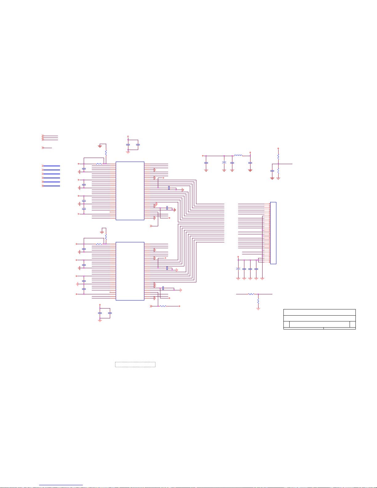
C
VP912
5
7
Thursday, June 24, 2004
LVDS CONNECTOR
Title
Size Document Number
Rev
Date:
Sheet
of
Vcont
RxOIN1-
DBO0
DGO2
DRO7
DCLK
DEN
RxOIN0+
RxOIN0+
DGE7
DBO1
DBE6
RxOCLKIN+
DGE2
DGE6
RxOIN2-
RxEIN2-
DRE3
DBE4
DGO0
DBE7
DBO6
DEN
RxOIN2-
DBO2
DRO1
RxECLKIN+
RxEIN0+
DBE3
DRO0
RxOIN2+
RxOIN0-
Vcont
DGE3
RxEIN1+
DGE0
RxEIN3-
SELLVDS
DBO3
DVS
RxEIN2+
DGO5
RxEIN2+
RxOIN2+
RxEIN0-
RxOCLKIN+
DRE2
DRO3
DRO2
DRO4
RxOIN3+
DBE1
DCLK
DGO4
DGO1
DGE1
DBE2
DRE0
RxEIN1+
DVS
DHS
RxEIN0-
DBO7
RxEIN3+
DEN
RxOIN1+
RxEIN3+
RxOCLKIN-
DGE4
DRO6
RxOIN0-
RxOIN3-
DGO6
RxEIN2-
DRO5
DBE0
SELLVDS
DRE4
RxEIN0+
DBO4
RxOCLKIN-
DRE7
DGO3
DRE1
DHS
DGO7
DGE5
RxOIN3-
RxECLKIN-
DBE5
RxECLKIN+
DRE6
DRE5
RxEIN3-
RxOIN3+
DBO5
RxEIN1-
RxOIN1+
RxECLKIN-
RxOIN1-
RxEIN1-
DGO[0..7]4
DVS3
DGE[0..7]
4
DHS3
LVDSON3
DEN3
LVDSON3
DRE[0..7]4
DCLK3
DBE[0..7]
4
DBO[0..7]4
DRO[0..7]4
+3.3VL
+3.3VL
+3.3VD
+3.3VL
+3.3VL
+3.3VL
+3.3VL
+3.3VL
+3.3VL
+3.3VL
+3.3VL
+3.3VL
+3.3VL
+3.3VL
+3.3VL
+3.3VL
+3.3VL
VPL
+3.3VL
C138
0.1uF
C150
100uF/16V
R92
0R
C153
0.1uF
R86
10K
+
C137
10uF/16V
C139
0.1uF
JP8
HEADER 30
1
2
3
4
5
6
7
8
9
10
11
12
13
14
15
16
17
18
19
20
21
22
23
24
25
26
27
28
29
30
C173
0.1uF
R88
NC
C136
100pF
R91
NC
C147
0.1uF
C148
0.1uF
C155 0.1uF
C135
100pF
C154
0.1uF
C149 0.1uF
C157
100pF
C156
0.1uF
C158
100pF
U12
DS90CF383
1
2
3
4
6
5
13
21
7
8
9
17
10
11
12
14
15
16
18
19
20
22
23
24
25
27
28
30
26
51
52
54
55
56
53
29
31
32
33
34
35
36
37
38
39
40
41
42
43
44
45
46
47
48
49
50
VCC
TxIN5
TxIN6
TxIN7
TxIN8
GND
GND
GND
TxIN9
TxIN10
VCC
VCC
TxIN11
TxIN12
TxIN13
TxIN14
TxIN15
TxIN16
TxIN17
TxIN18
TxIN19
TxIN20
TxIN21
TxIN22
TxIN23
TxIN24
TxIN25
TxIN26
VCC
TxIN0
TxIN1
TxIN2
TxIN3
TxIN4
GND
GND
TxCLKIN
/PWRDWN
PLLGND
PLLVCC
PLLGND
LVDSGND
TxOUT3+
TxOUT3-
TxCLKOUT+
TxCLKOUT-
TxOUT2+
TxOUT2-
LVDSGND
LVDSVCC
TxOUT1+
TxOUT1-
TxOUT0+
TxOUT0-
LVDSGND
TxIN27
U13
DS90CF383
1
2
3
4
6
5
13
21
7
8
9
17
10
11
12
14
15
16
18
19
20
22
23
24
25
27
28
30
26
51
52
54
55
56
53
29
31
32
33
34
35
36
37
38
39
40
41
42
43
44
45
46
47
48
49
50
VCC
TxIN5
TxIN6
TxIN7
TxIN8
GND
GND
GND
TxIN9
TxIN10
VCC
VCC
TxIN11
TxIN12
TxIN13
TxIN14
TxIN15
TxIN16
TxIN17
TxIN18
TxIN19
TxIN20
TxIN21
TxIN22
TxIN23
TxIN24
TxIN25
TxIN26
VCC
TxIN0
TxIN1
TxIN2
TxIN3
TxIN4
GND
GND
TxCLKIN
/PWRDWN
PLLGND
PLLVCC
PLLGND
LVDSGND
TxOUT3+
TxOUT3-
TxCLKOUT+
TxCLKOUT-
TxOUT2+
TxOUT2-
LVDSGND
LVDSVCC
TxOUT1+
TxOUT1-
TxOUT0+
TxOUT0-
LVDSGND
TxIN27
R85
NC
L12
Bead /1206
C146
0.1uF
C142
0.1uF
C145 0.1uF
C144
0.1uF
C143 0.1uF
C141
0.1uF
R90 NC
R89
NC
R87 NC
R93
4.7k
C151
0.1uF
C152
0.1uF
C140
0.1uF
76
ViewSonic Corporation Confidential - Do Not Copy VP912s/b
Page 80

74LVC126
PIN14
(KEYPAD)
Option for Pivot SW
VP912
C
KEYPAD & DDC
67
Thursday, June 24, 2004
Title
Size Document Number
Rev
Date:
Sheet
of
KSELECT
KMENU
KLEDG
KPWR
KLEDR
KDOWN
KUP
KMENU
KSELECT
KDOWN
KUP
KLEDG
KLEDR
KPWR
VS_DSUB22
SCL_IN12
SDA_IN12
SCL_IN22
SDA_IN22
HS_DSUB22
HS_DSUB12
VS_DSUB12
MUX_SEL
2,3
DDCSCL1
3
DDCSCL2
3
DDCSDA2
3
DDCSDA1
3
ROTATE3
MENU 3
SELECT 3
DOWN 3
UP 3
PWR_SW 3
LEDG 3
LEDR 3
HS 3
VS 3
+3.3VD
+3.3VD
+3.3VD
DSUB2_5V +5V
GND
GND
DSUB1_5V +5V
GND
GND
+3.3VD
R99 100
R102 NC
R118
2.2K
R103 NC
R117 100
C167
0.1uF
R123 100R
R109 10K
R94
2.2K
R122 100R
JP9
Ball Switch
12
34
C174 0.1uF
R106
510
R104 0
R115
2.2K
U16C
74LVC126
9 8
10
R112 33
R105 0
R124 1k
RP15
1k
1 8
2 7
3 6
4 5
U14
PCB2421
4
81
2
3
7
6
5
GND
VCCA0
A1A2WP
SCL
SDA
CP14
NC
12736
45
8
U16D
74LVC126
12 11
13
R100
100
C169
0.1uF
C162
22pF
R97
2.2K
R110
0
C160
0.1uF
C168
0.1uF
JP11
SMD
1
2
3
4
5
6
7
8
9
10
R114
2.2K
R116 100
R101 100
R113 33
R120
NC
R96
2.2K
C164
47pF
U15
PCB2421
4
81
237
6
5
GND
VCCA0
A1A2WP
SCL
SDA
C159
0.1uF
R95
2.2K
12
3
SOT23
D5
BAV70
C166
47pF
R98
100
R119
2.2K
C161
0.1uF
C175
0.1uF
C177
0.1uF
R108
4.7K
R126
510R
C163
47pF
R125
510R
C165
47pF
U16B
74LVC126
5 6
4
U16A
74LVC126
2 3
1
12
3
SOT23
D4
BAV70
JP10
HEADER 12-2.0
1
2
3
4
5
6
7
8
9
10
11
12
Q6
DTC144
R121 NC
R131 33
C179
22pF
R130 33
RP14
10k
1 8
2 7
3 6
4 5
R107
10k
R111 NC
C178
22pF
77
ViewSonic Corporation Confidential - Do Not Copy VP912s/b
Page 81

11. PCB Layout Diagrams
78
ViewSonic Corporation Confidential - Do Not Copy VP912s/b
Page 82

*Readers Response*
Dear Readers:
Thank you in advance for your feedback on our Service Manual, which allows continuous improvement
of our products. We would appreciate your completion of the Assessment Matrix below, for return to
ViewSonic Corporation.
Assessment
Readers basic data:
After completing this form, please return it to ViewSonic Quality Assurance
metI tnellecxE dooG riaF daB
.1
.2
.3
tinU riaF daB
in the USA at facsimile
1-909-839-7943.
You may also e-mail any suggestions to the Director, Quality Systems & Processes
(marc.maupin@viewsonic.com)
dooGtnellecxE
Precautions and Safety Notices
1.
8. Exploded Diagram and Spare Parts List
7. Recommended Spare Parts List
Adjustment Procedure
2. Specification
5.
4. Circuit Description
3.
6. Troubleshooting Flow Chart
Front Panel Function Control Description
9. Block Diagram
10. Schematic Diagrams
11. PCB Layout Diagrams
Service Manual Content
Service Manual Layout
The form and listing
Name: Title:
Company:
Add.:
Tel:
E-mail:
Fax:
A. What do you think about the content of the VP912s/b Service Manual?
B. Are you satisfied with the VP912s/b Service Manual?
C. Do you have any other opinions or suggestions regarding this service manual?
79
ViewSonic Corporation Confidential
-
Do Not Copy VP912s/b
 Loading...