

ViewSonic VG500b-1, VLCDS24349-1 Service Manual

Service Manual
ViewSonic VG500b-1
Model No. VLCDS24349-1
15” Digital Controlled Color Monitor
(VG500b-1_SM_574-Rev. 1.0-October 2002)
ViewSonic
381 Brea Canyon Road, Walnut, California 91789 USA - (800) 888-8583
Copyright
Copyright
¤
2002 by ViewSonic Corporation. All rights reserved. No part of this publication may be
reproduced, transmitted, transcribed, stored in a retrieval system, or translated into any language or
computer language, in any form or by any means, electronic, mechanical, magnetic, optical, chemical,
manual or otherwise, without the prior written permission of ViewSonic Corporation.
Disclaimer
ViewSonic makes no representations or warranties, either expressed or implied, with respect to the
contents hereof and specifically disclaims any warranty of merchantability or fitness for any particular
purpose. Further, ViewSonic reserves the right to revise this publication and to make changes from time
to time in the contents hereof without obligation of ViewSonic to notify any person of such revision or
changes.
Trademarks
ViewSonic is a registered trademark of ViewSonic Corporation.
All other trademarks used within this document are the property of their respective owners.
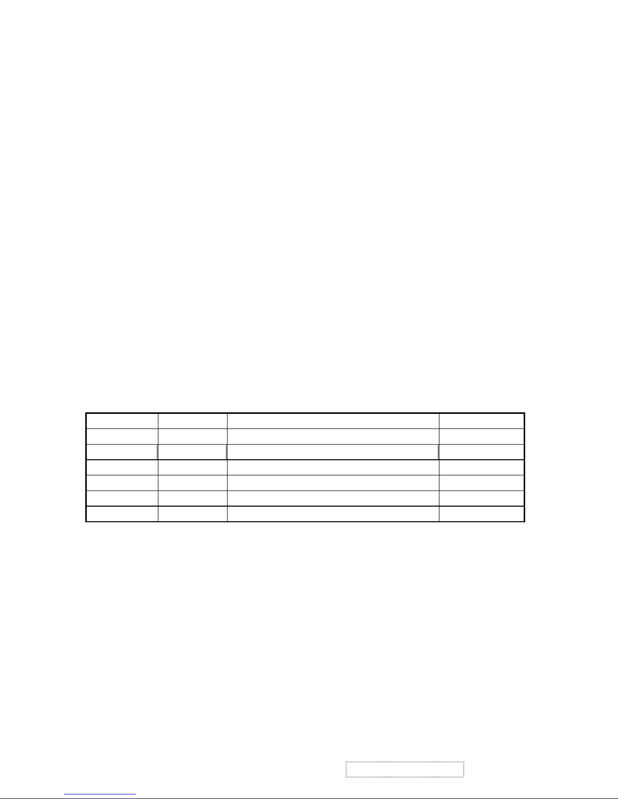
Revision History
Revision Date Description Of Changes Approval
1a 10/01/02 Initial Release DCN-2350 K.Yang
ViewSonic Corporation
i
VG500b-1 Confidential – Do Not Copy
1b 10/31/02 Revise DCN-2350
C.Shen

TABLE OF CONTENTS
1. Precautions and notices ..................................................................1
2. Service Tool and Equipment Required........................................2
3. Specifications...............................................................................3
4. Internal Connector Pin Assignment.................................................6
5. Troubleshooting Flow Chart.....................................................10
6. Adjustment................................................................................14
7. Theory of Operation...................................................................15
8. Electrical Parts List..................................................................16
10. Block Diagram.........................................................................21
11. Schematic Diagrams.................................................................22
12. PCB Layout DiagramS..............................................................31
9.. Exploded Diagram and Mechanical Parts List........................19
ViewSonic Corporation
ii
VG500b-1 Confidential – Do Not Copy

1. PRECAUTION AND NOTICES
SAFETY PRECAUTIONS
This monitor is manufactured and tested on a ground principle that a user’s safety comes
first. However, improper used or installation may cause damage to the monitor as well as
to the user.
WARNINGS:
z This monitor should be operated only at the correct power sources indicated on the
label on the rear of the monitor. If you’re unsure of the power supply in your residence,
consult your local dealer or Power Company.
z Use only the special power adapter that comes with this monitor for power input.
z Do not try to repair the monitor by yourself, as it contains no user-serviceable parts.
This monitor should only be repaired by a qualified technician.
z Do not remove the monitor cabinet. There are high-voltage parts inside that may cause
electric shock to human bodies.
z Stop using the monitor if the cabinet is damaged. Have it checked by a service
technician.
z Put your monitor only in a clean, cool, dry environment. If it gets wet, unplug the power
cable immediately and consult your local dealer.
z Always unplug the monitor before cleaning it. Clean the cabinet with a clean, dry cloth.
Apply non-ammonia based cleaner onto the cloth, not directly onto the glass screen.
z Do not place heavy objects on the monitor or power cord.
PRODUCT SAFETY NOTICE
Many electrical and mechanical parts in this chassis have special safety visual inspections
and the protection afforded by them cannot necessarily be obtained by using replacement
components rated for higher voltage, wattage, etc. Before replacing any of these
components read the parts list in this manual carefully. The use of substitute replacement
parts, which do not have the same safety characteristics as specified in the parts list, may
create shock, fire, or other hazards.
SERVICE NOTES
1. When replacing parts or circuit boards, clamp the lead wires around terminals before
soldering.
2. Keep wires away from high voltage, high temperature components and sharp edges.
3. Keep wires in their original position so as to reduce interference.
4. Adjustment of this product please refer to the user’ manual.
1.
PRECAUTIONS AND NOTICES
ViewSonic Corporation
1
VG500b-1 Confidential – Do Not Copy

SERVICE TOOLS & EQUIPMENT REQUIRED
1. SIGNAL GENERATOR: Chroma 2237 or equivalent
2. MULTIMETER Fluke 45 or equivalent
3. SCREW DRIVER
4. OSCILLOSCOPE Tektronik TDS3054 digital oscilloscope or equivalent
5. SOLDER IRON
2. SERVICE TOOL AND EQUIPMENT REQUIRED
ViewSonic Corporation
2
VG500b-1 Confidential – Do Not Copy

SPECIFICATIONS
3.1 PRODUCT SPECIFICATIONS
LCD Panel 15.0” TFT
Power Management ENERGY Star compliant VESA
DPMS compatible
<2W
Displayable Resolution XGA, 1024x768 (max.)
Pixel Dimension 0.2907(H) x 0.2907(V) mm
LCD Display Color 16.7M color (max.)
Viewing Angle CR>10
Horizontal: -60˚~+60˚
Vertical: -55˚~+45˚
Tilt -5˚~20˚
Contrast Ratio
Brightness
400:1 typical
250:1 minimum
200cd/m² (min)
250cd/m² (typ.)
Response Time Tr: 7ms, Tf: 23ms
Active Display Area 304.1mm(H) x 228.1mm(V)
Temperature Operating: 0˚C~+40˚
Storage: -20˚C~+60˚
Compliance UL, CSA, FCC, CE, CB, BSMI, ENERGY Star, TUV,
Semko, Nemko, Fimko, Demko, DHHS, MPRII, TCO95,
GOST-R, C-Tick, VCCI, CCC, PCT, NOM, PCBC
Power Input Voltage: 100~240 Vac
Consumption: 36 Watts (Max.)
3.
SPECIFICATIONS
ViewSonic Corporation
3
VG500b-1 Confidential – Do Not Copy
C
C
3.2. SUPPORTING MODES
Primary Preset: VESA 1024 x 768 @ 60Hz
Factory Preset Modes:
1. VGA 640x350 @ 70Hz, 25.176MHz
2. VESA 640x480 @ 60Hz, 25.175MHz
3. MAC 640x480 @ 67Hz, 31.500MHz
4. VESA 640x480 @ 72Hz, 31.50MHz
5. VESA 640x480 @ 75Hz, 31.50MHz
6. VESA 720x400 @ 70Hz, 28.320MHz
7. VESA 800x600 @ 56Hz, 36.00MHz
8. VESA 800x600 @ 60Hz, 40.00MHz
9. VESA 800x600 @ 72Hz, 50.00MHz
10. VESA 800x600 @ 75Hz, 49.5MHz
11. MAC 832x624 @ 75Hz, 57.272MHz
12. VESA 1024x768 @ 60Hz, 65MHz
13. VESA 1024x768 @ 70Hz, 75.000MHz
14. VESA 1024x768 @ 72Hz, 78.000MHz
15. MAC 1024x768 @ 75Hz, 80.000MHz
16. VESA 1024x768 @ 75Hz, 78.750MHz
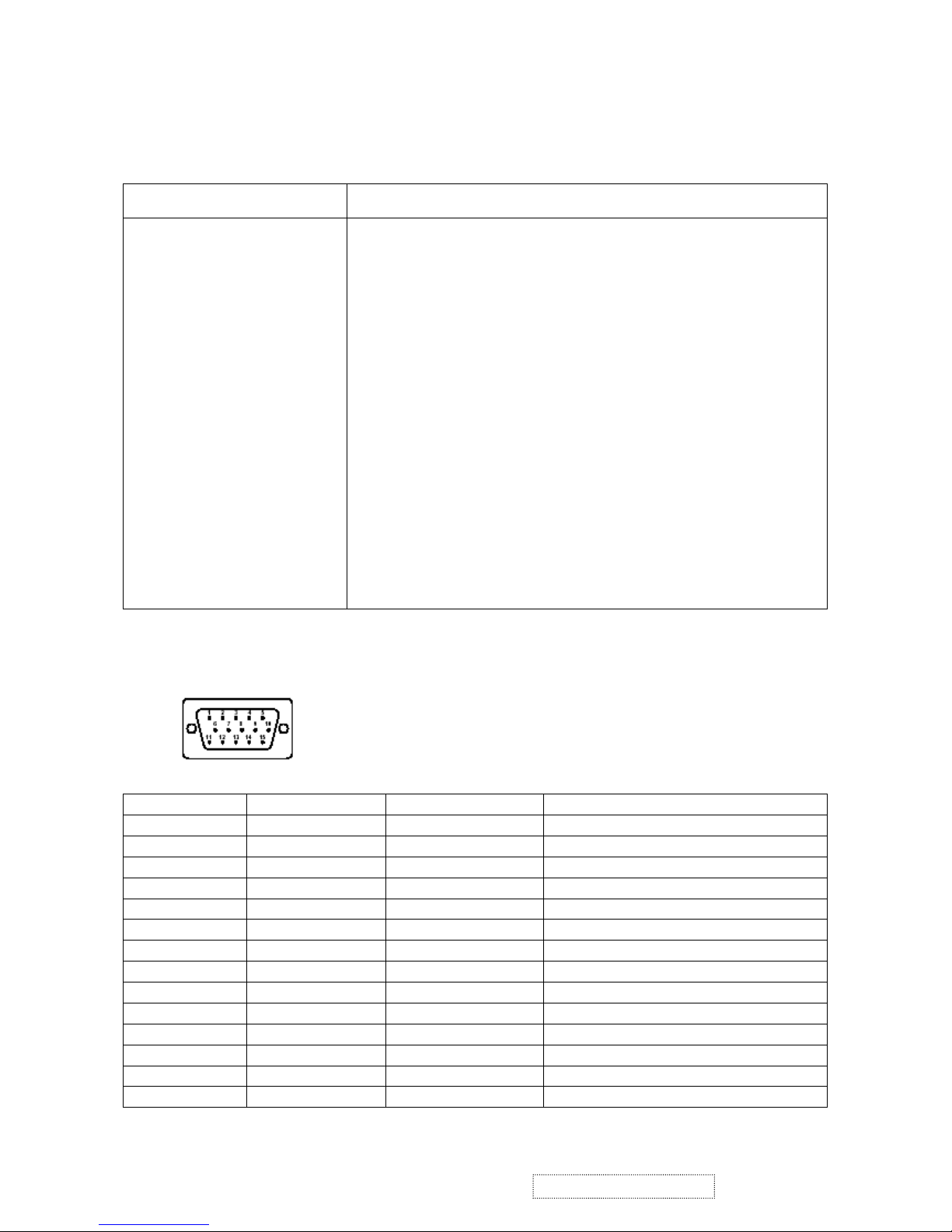
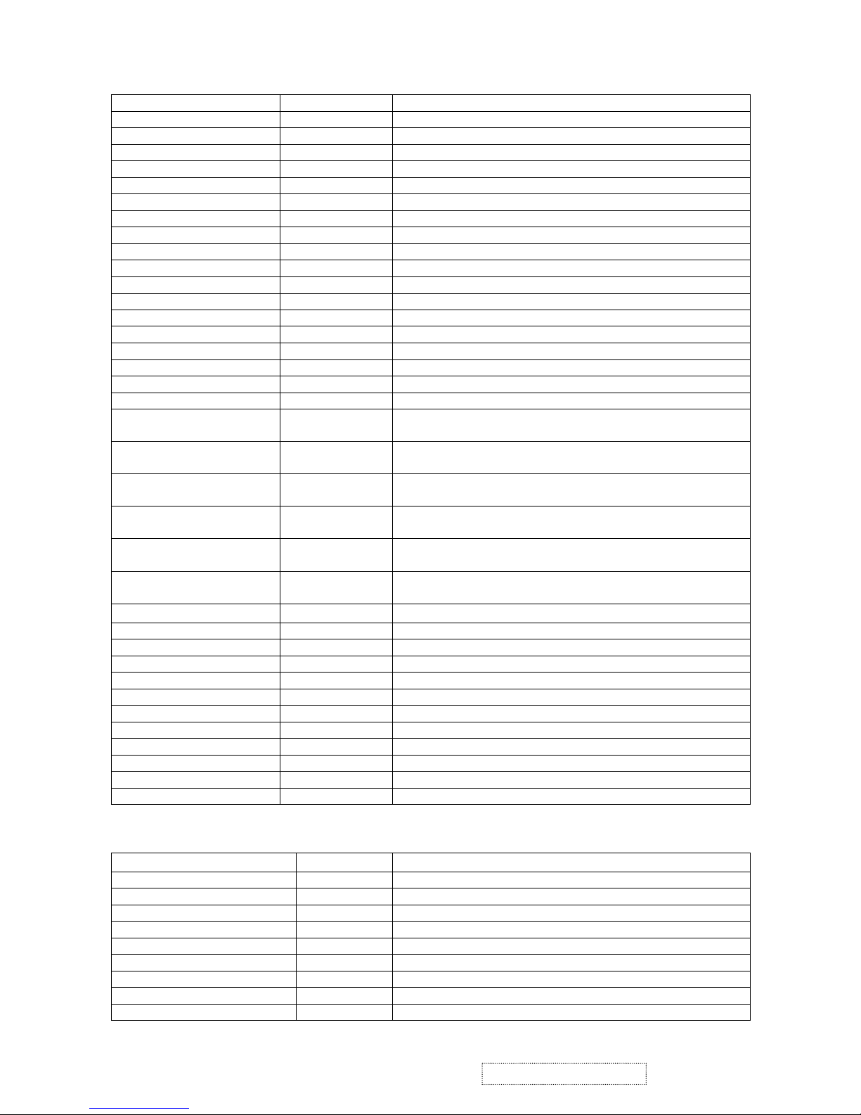
3.3. D-SUB CONNECTOR PINASSIGNMENT
Pin No. Symbol Signal Description
1 R RED 0.7vp-p (VIDEO)
2 G GREEN 0.7vp-p (VIDEO)
3 B BLUE 0.7vp-p (VIDEO)
4 GND GROUND
5 GND GROUND
6 GND GROUND
7 GND GROUND
8 GND GROUND
9 VCC_+5V PC +5V
10 GND GROUND
11 N.C.
12 DDC_SDA DDC1/2B TTL
13 DDC_SCL DDC1/2B TTL
14 VGA_VSYNC VSYNC TTL positive or negative
ViewSonic Corporation
4
VG500b-1 Confidential – Do Not Copy
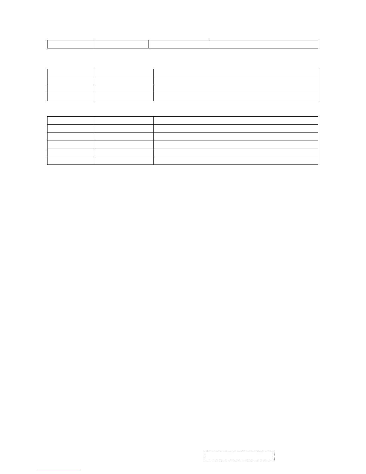
15 VGA_HSYNC HSYNC TTL positive or negative
3.4 Main DC+12V Input (J800 on I/F Board)
Pin No. Symbol Function
1 GND Ground
2 DC+12V Main DC+12V Input
3 GND Ground
3.5 Audio Input Jack (J701 on I/F Board)
Pin No. Symbol Function
1 Ground
2 L_CH_Audio Input
3 R_CH_Audio Input
4 L_CH_Audio Return
5 R_CH_Audio Return
ViewSonic Corporation
5
VG500b-1 Confidential – Do Not Copy
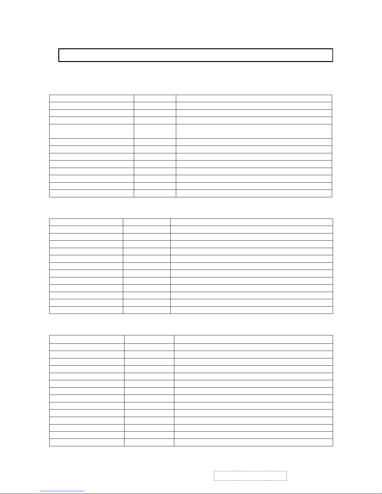
XGA Interface Board (LIF-007)
JP2 (T-S12BZR): Connect with Control board
Pin No. Symbol Function
1 Mute OSD, Audio Mute Function Button
2 SP- Adjust audio volume smaller
3 SP+ Adjust audio volume louder
4 Menu
Call out or close the OSD menu or come back to the previous
menu
5 Down Choose the next one item or value
6 Up Choose the last one item or value
7 Sel Select
8 GND Ground
9 Amber Indicate the system in power saving mode
10 Green Indicate the system in active mode
11 GND Ground
12 Power Power on/off control port
CON220 (T-B12B-ZR): Connect to the LOR-002, which is power/audio board
Pin No. Symbol Function
1 SENSOR Detect audio I/P signal
2 GND Ground
3 +12V DC+12V
4 GND Ground
5 CCFL_EN Backlight lamps ON(high)/Off(Low) control
6 GPIO2/PWM2 Brightness adjustments (Low Max./ Hi. Min.)
7 MUTE+ Audio Must control (High means SPK off, Low means On)
8 GND Ground
9 +5V DC+5V
10 +5V DC+5V
11 STDBY Audio Stand-by control (Hi means stand-by, Low means Normal)
12 VOLUME Speaker volume control (0V means Sound off, 1.2V means MAX.)
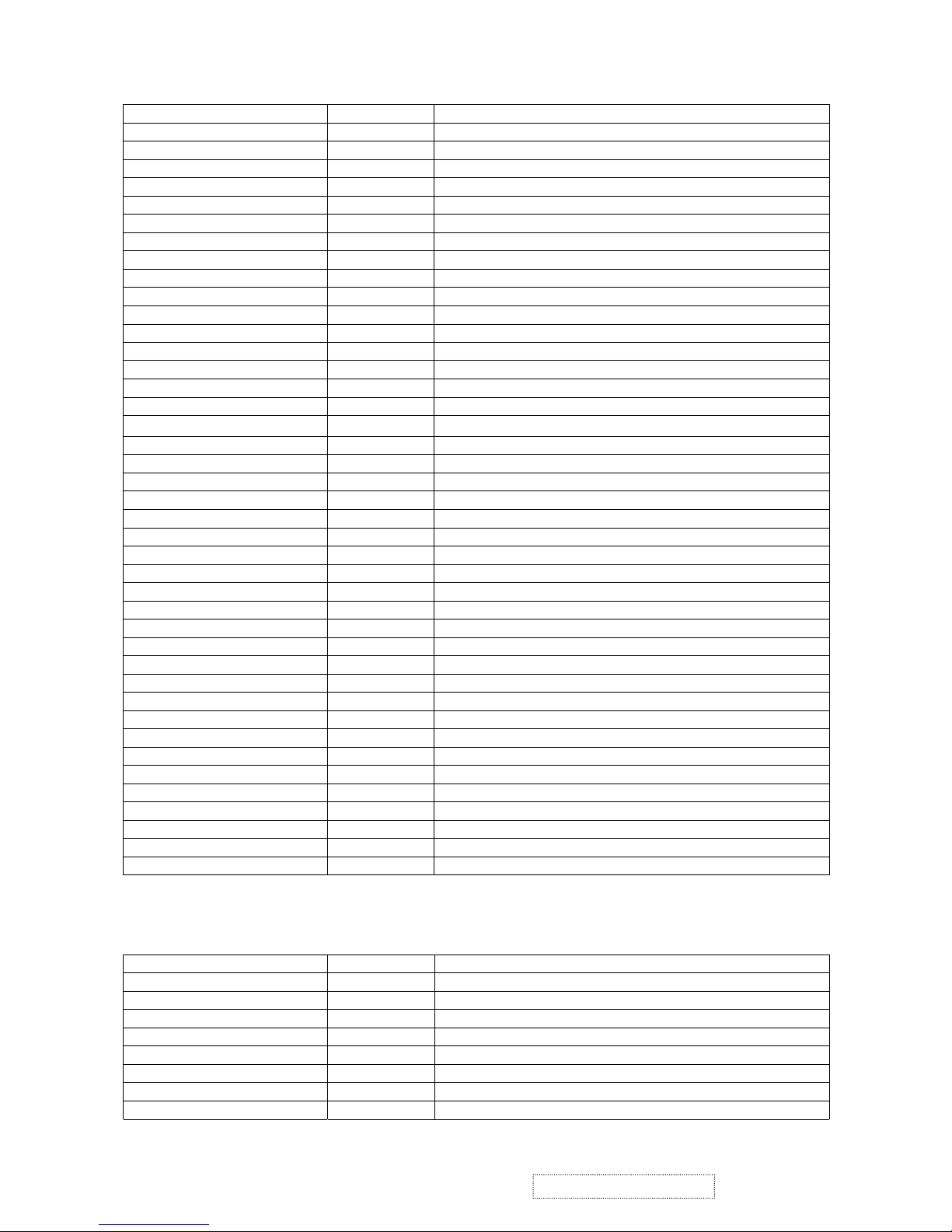
CN501 (IL-FHR-50S-HF): Output to panel
Pin No. Symbol Function
1 GND Ground
2 GND Ground
3 CLKH- Sampling Clock for line pixels
4 GND Ground
5 GND Ground
6 OB7 Blue data signal of odd pixel
7 OB6 Blue data signal of odd pixel
8 OB5 Blue data signal of odd pixel
9 OB4 Blue data signal of odd pixel
10 OB3 Blue data signal of odd pixel
11 OB2 Blue data signal of odd pixel
12 OB1 Blue data signal of odd pixel
13 OB0 Blue data signal of odd pixel
14 GND Ground
4. INTERNAL CONNECTOR PIN ASSIGNMENT
ViewSonic Corporation
6
VG500b-1 Confidential – Do Not Copy
15 OG7 Green data signal of odd pixel
16 OG6 Green data signal of odd pixel
17 OG5 Green data signal of odd pixel
18 OG4 Green data signal of odd pixel
19 OG3 Green data signal of odd pixel
20 OG2 Green data signal of odd pixel
21 OG1 Green data signal of odd pixel
22 OG0 Green data signal of odd pixel
23 GND Grounding
24 OR7 Red data signal of odd pixel
25 OR6 Red data signal of odd pixel
26 OR5 Red data signal of odd pixel
27 OR4 Red data signal of odd pixel
28 OR3 Red data signal of odd pixel
29 OR2 Red data signal of odd pixel
30 OR1 Red data signal of odd pixel
31 OR0 Red data signal of odd pixel
32 GND Ground
33 GND Ground
34 VDDA
DC+9V for panel D/A reference voltage to make gray scale
smooth
35 VDDA
DC+9V for panel D/A reference voltage to make gray scale
smooth
36 VDDA
DC+9V for panel D/A reference voltage to make gray scale
smooth
37 VDDA
DC+9V for panel D/A reference voltage to make gray scale
smooth
38 VDDA
DC+9V for panel D/A reference voltage to make gray scale
smooth
39 VDDA
DC+9V for panel D/A reference voltage to make gray scale
smooth
Pin No. Symbol Function
40 GND Ground
41 GND Ground
42 GND Ground
43 GND Ground
44 EPOL O/E reference voltage selection
45 HMS2_E Even pixel inverter for power saving and reducing EMI
46 HMS1_O Odd pixel inverter for power saving and reducing EMI
47 DHS_LP Latch pulse for per line
48 STH1 Trigger the first pixel per line
49 GND Ground
50 GND Ground
CN502 (IL-FHR-50S-HF): Output to panel
Pin No. Symbol Function
1 GND Ground
2 GND Ground
3 VEEG DC-6V for frame dark
4 VEEG DC-6V for frame dark
5 VDDG DC+18V for frame white
6 VDDG DC+18V for frame white
7 CLKV Sampling Clock for frame line
8 STV1 Trigger the first line per frame
9 VDDD DC_3.3V for panel VCC
ViewSonic Corporation
7
VG500b-1 Confidential – Do Not Copy
10 VDDD DC_3.3V for panel VCC
11 VDDD DC_3.3V for panel VCC
12 VDDD DC_3.3V for panel VCC
13 VDDD DC_3.3V for panel VCC
14 VDDD DC_3.3V for panel VCC
15 VCOM Panel flicker adjustment, Adjustable voltage from DC3.3V ~4V
16 VCOM Panel flicker adjustment, Adjustable voltage from DC3.3V ~4V
17 VCOM Panel flicker adjustment, Adjustable voltage from DC3.3V ~4V
18 VCOM Panel flicker adjustment, Adjustable voltage from DC3.3V ~4V
19 VCOM Panel flicker adjustment, Adjustable voltage from DC3.3V ~4V
20 VCOM Panel flicker adjustment, Adjustable voltage from DC3.3V ~4V
21 GND Ground
22 GND Ground
23 EB7 Blue data signal of even pixel
24 EB6 Blue data signal of even pixel
25 EB5 Blue data signal of even pixel
26 EB4 Blue data signal of even pixel
Pin No. Symbol Function
27 EB3 Blue data signal of even pixel
28 EB2 Blue data signal of even pixel
29 EB1 Blue data signal of even pixel
30 EB0 Blue data signal of even pixel
31 GND Ground
32 EG7 Green data signal of even pixel
33 EG6 Green data signal of even pixel
34 EG5 Green data signal of even pixel
35 EG4 Green data signal of even pixel
36 EG3 Green data signal of even pixel
37 EG2 Green data signal of even pixel
38 EG1 Green data signal of even pixel
39 EG0 Green data signal of even pixel
40 GND Ground
41 ER7 Red data signal of even pixel
42 ER6 Red data signal of even pixel
43 ER5 Red data signal of even pixel
44 ER4 Red data signal of even pixel
45 ER3 Red data signal of even pixel
46 ER2 Red data signal of even pixel
47 ER1 Red data signal of even pixel
48 ER0 Red data signal of even pixel
49 GND Ground
50 GND Ground
POWER/AUDIO Board (LOR-002)
JP2 (T-B12B-ZR): Connect to the I/F Board
Pin No. Symbol Function
1 Volume Speaker volume control (0V sound off, 1.2V sound Max.)
2 Stdby Audio standby control (High standby, Low normal)
3 DC+5V DC+5V
4 DC+5V DC+5V
5 GND Ground
6 MUTE+ Audio mute control (Voltage High speaker off, Low speaker on)
7 BRT Brightness adjustment (Low is max., High is Min.)
8 CCFL_EN Backlight lamps enable (ON/high, OFF/low)
ViewSonic Corporation
8
VG500b-1 Confidential – Do Not Copy
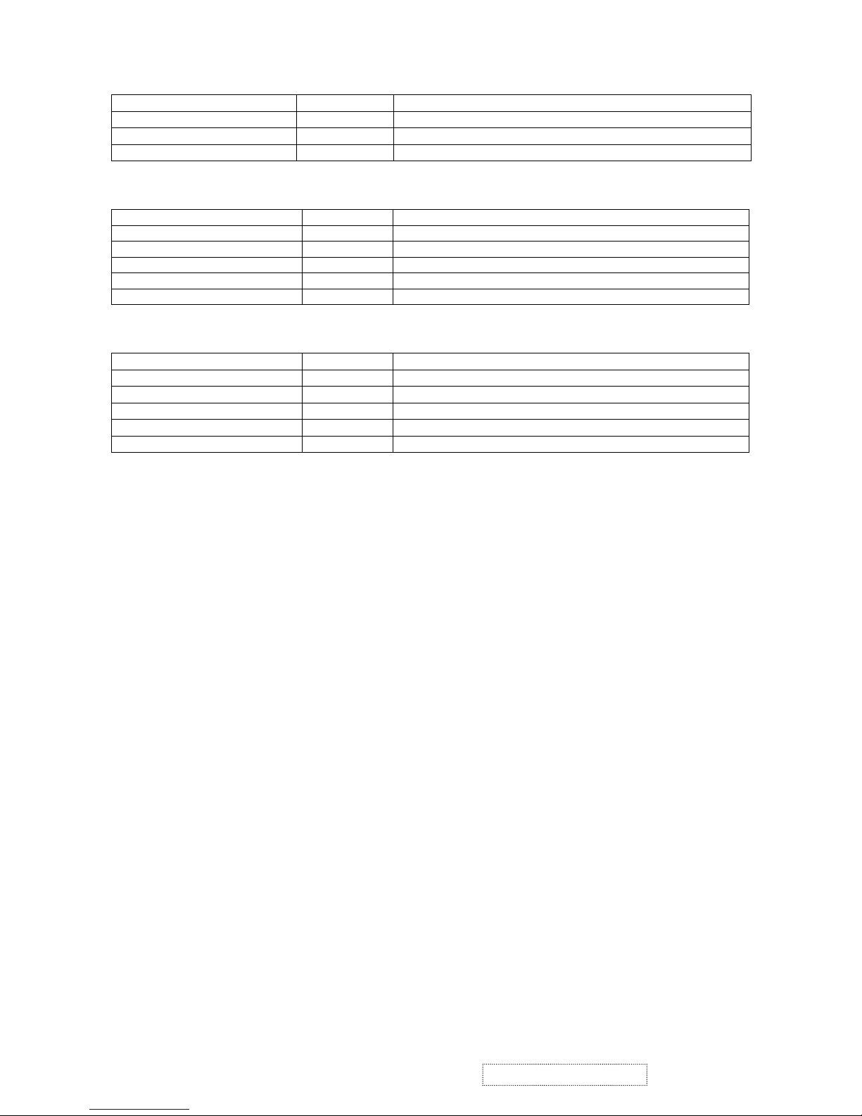
9 GND Ground
10 DC+12V DC+12V
11 GND Ground
12 SENSOR Detect audio I/P signal
CN830 (S5B-PH-K): Connect to inverter
Pin No. Symbol Function
1 DC+12V DC+12V
2 GND Ground
3 BRT Brightness adjustment (Low is Max., High is Min.)
4 DC+5V DC+5V
5 CCFL_EN Backlight lamps enable (ON/high, OFF/low)
CN701 (S5BPH-K): Connect to control board, control the audio
Pin No. Symbol Function
1 L- L_CH_SP_-Signal
2 L+ L_CH_SP_+Signal
3 GND_S1 Ground
4 R+ R_CH_SP_-Signal
5 R- R_CH_SP_+Signal
ViewSonic Corporation
9
VG500b-1 Confidential – Do Not Copy
 Loading...