

ViewSonic VG900b-1, VLCDS24020-2W Service Manual

Service Manual
ViewSonic VG900b-1
(VG900b-1_SM_575-Rev. 1.0-October 2002)
ViewSonic
381 Brea Canyon Road, Walnut, California 91789 USA - (800) 888-8583
Model No. VLCDS24020-2W
19” Color TFT LCD Display
Copyright
Copyright ¤ 2002 by ViewSonic Corporation. All rights reserved. No part of this publication may be
reproduced, transmitted, transcribed, stored in a retrieval system, or translated into any language or
computer language, in any form or by any means, electronic, mechanical, magnetic, optical, chemical,
manual or otherwise, without the prior written permission of ViewSonic Corporation.
Disclaimer
ViewSonic makes no representations or warranties, either expressed or implied, with respect to the
contents hereof and specifically disclaims any warranty of merchantability or fitness for any particular
purpose. Further, ViewSonic reserves the right to revise this publication and to make changes from time
to time in the contents hereof without obligation of ViewSonic to notify any person of such revision or
changes.
Trademarks
ViewSonic is a registered trademark of ViewSonic Corporation.
All other trademarks used within this document are the property of their respective owners.
Revision History
Revision Date Description Of Changes Approval
1a 10/2/02 Initial Reversion DCN-2351 K.Yang
ViewSonic Corporation
i
Confidential – Do Not Copy
VG900b-1
1b 11/11/02 Revise DCN-2351 C.Shen

TABLE OF CONTENTS
ViewSonic Corporation
ii
Confidential – Do Not Copy
VG900b-1
1.
PRECAUTIONS AND NOTICES...............................................................................1
2.
SPECIFICATIONS ....................................................................................................2
3.
LOCATION OF CONTROLS.....................................................................................3
5. BLOCK DIAGRAM....................................................................................................9
6. TROUBLE SHOOTING FLOW CHART...................................................................11
7. SPARE PARTS LIST...............................................................................................15
8. EXPLODED DIAGRAM AND SPARE PARTS LIST................................................23
9.
SCHEMATIC DIAGRAMS........................................................................................25
10. PCB LAYOUT DIAGRAM........................................................................................35
4.
ADJUSTING PROCEDURE......................................................................................4

1.
PRECAUTIONS AND NOTICES
Prior to using this manual, please ensure that you have carefully followed all the procedures outlined in
the user manual for this product.
Read all of these instructions.
Save these instructions for later use.
Follow all warnings and instructions marked on the product.
Do not use this product near water.
This display should be installed on a solid horizontal base.
When cleaning, use only a neutral detergent cleaner with a soft damp cloth. Do not spray with liquid or
aerosol cleaners.
Do not expose this display to direct sunlight or heat. Hot air may cause damage to the cabinet and other
parts.
Adequate ventilation must be maintained to ensure reliable and continued operation and to protect the
display from overheating. Do not block ventilation slots and openings with objects or install the display
in a place where ventilation may be hindered.
Do not install this display near a motor or transformer where strong magnetism is generated. Images
on the display will become distorted and the color irregular.
Do not allow metal pieces or objects of any kind fall into the display from ventilation holes.
Slots and openings in the cabinet and the back or bottom are provided for ventilation, to ensure reliable
operation of the product and to protect it from overheating, those openings must not be blocked or
covered. Those openings should never be blocked by placing this product on a bed, sofa, rug, or other
similar surface. This product should never be placed near or over a radiator or heat register. This
product should not be placed in a built-in installation unless proper ventilation is provided.
ViewSonic Corporation
1
Confidential – Do Not Copy
VG900b-1

2.
SPECIFICATIONS
1.
Specifications
LCD panel type
19.0” TFT(Fujitsu)
Power Consumption
48 W (typ)
Displayable Resolution
SXGA 1280 x 1024 maximum
Pixel dimension
0.294 mm x 0.294 mm
Display Color
16.7 M
Viewing Angle
(CR=10)
Horizontal: ±85
q
Vertical: ±85
q
Response Time
25 ms typ.
Contrast Ratio
500:1 typ.
Brightness
250 cd / m2 typ.
Active Display Area
376 mm horizontal x 301mm vertical
AC/DC adapter
Input:AC 100~264V,47~63 Hz
Output:+12V DC.
Dimensions ( WxHxD )
439 mm(W) x 465mm(H) x 180mm(D)
Weight
7.5 kg (unit)
Input connector
15 Pin D-Sub.
Power management
YES
Temperature
Operating : 0°C ~ +40°C
Storage : -20°C ~ +60°C
ViewSonic Corporation
2
Confidential – Do Not Copy
VG900b-1
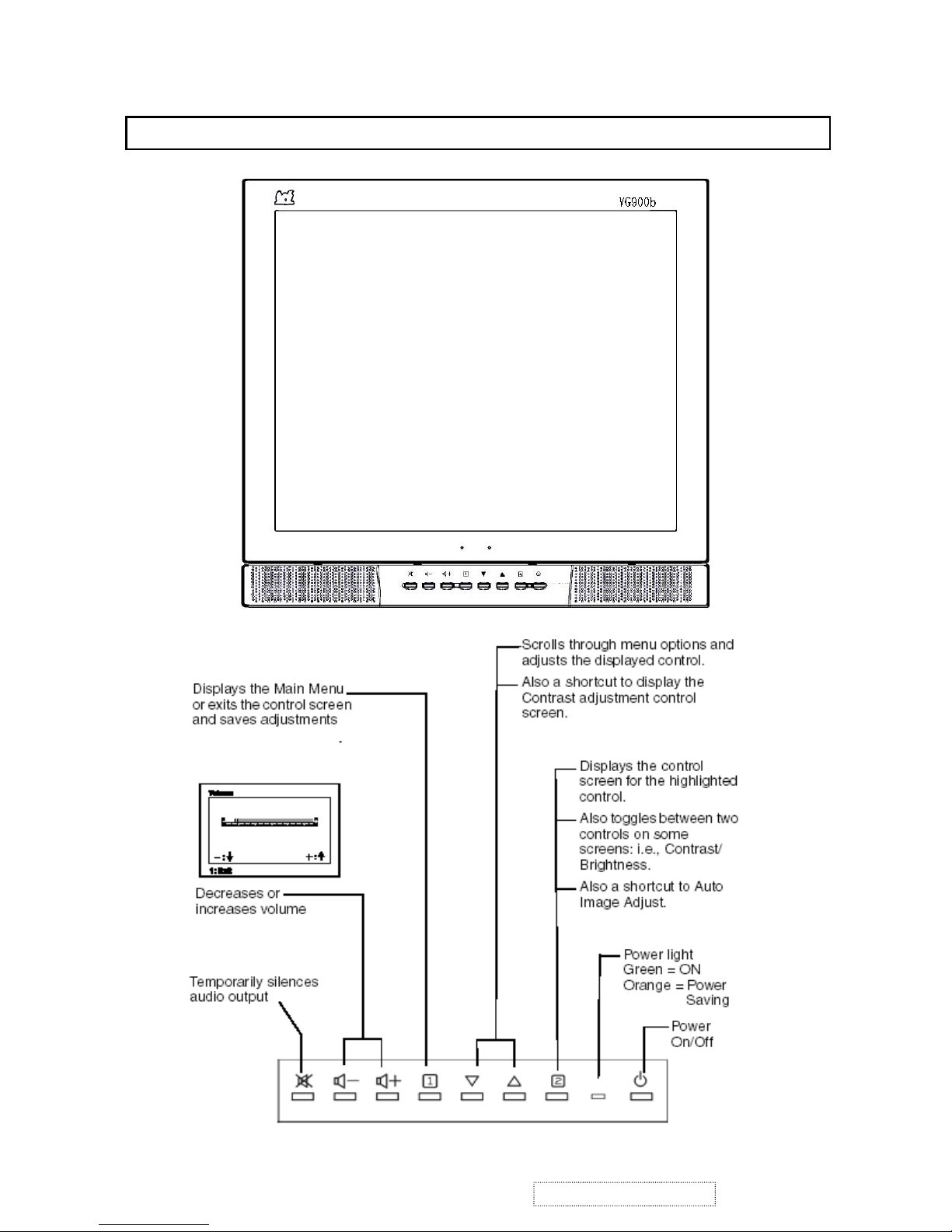
3.
LOCATION OF CONTROLS
3.
LOCATION OF CONTROLS
ViewSonic Corporation
3
Confidential – Do Not Copy
VG900b-1

The " adjusting procedure" of VG900b model
1. Turn off the display by power button key on the front of bezel,
2. Disconnect the DC power cable from power jack at rear side.
3. Press and hold the “Ÿ” button key on the front of the bezel
4. Connect the power cable with power jack, and keep pressing the “Ÿ” button key.
5. Press the power button key to turn the display on, and then release the “Ÿ” and power button.
6. The unit is set into Reset mode, OSD main window will be shown on the display,
you can see a red message for “ALL RESET” with a red frame inside OSD windows.
7. The LED lights up with orange and change to green color during reset procedure.
8. OSD changes into a message for "Auto Image Adjust", it disappears after reset procedure.
9. The input video signal is shown on display.
4.
ADJUSTING PROCEDURE
ViewSonic Corporation
4
Confidential – Do Not Copy
VG900b-1
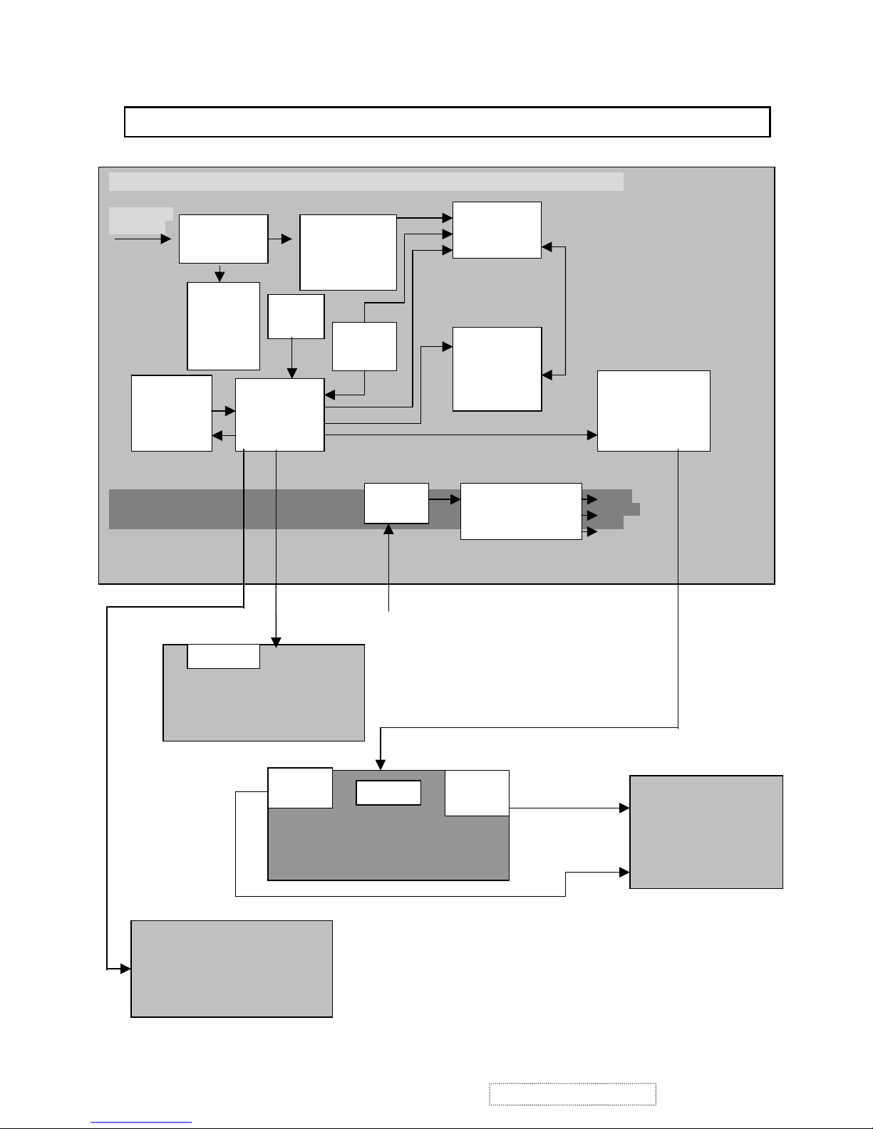
5.
BLOCK DIAGRAM
FROM
A/D ADAPTOR
INTERFACE BOARD(DPWBN5419T8---A)
COMPUTER
GRAPHIC
12V
3.3V
5V
W1
(DB15)
A/D
CONVERTER
AD9883
(U3)
SCALER
SD1210-2
(U8)
DDC
EPROM
24C21A
(U5)
Serial
EEPROM
24C16
(U17)
MPU
(U15)
MTV230P
Serial
EEPROM
24C16
(U9)
JP2
TO
INVERTER
JP3
SWITCH MODE
POWER SUPPLY
19” LCD
PANEL
SW BOARD
DPWBN5418T8----
INVERTER
RUNTP5392T8----
CON1
CON4
5CON
CON2
CON3
JP7
X1
OSC
PLL
U12
AUDIO BOARD
DPWBN5417T8----
ViewSonic Corporation
5
Confidential – Do Not Copy
VG900b-1
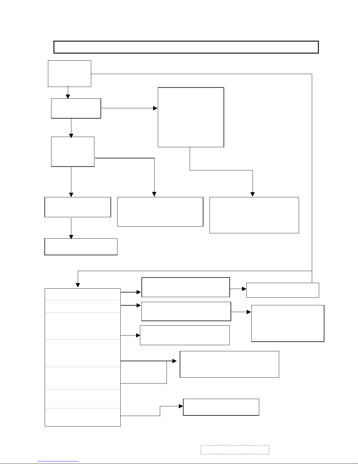
YES
NO
ON
OFF
GREEN
Hsync,Vsync
Or DE error
ORANGE
OSD no response
Picture too dim
The brightness is
different between upper
and lower side of panel
Picture without
Color
Vertical, Horizontal
Out of sync
One or more colored
vertical lines
Even (or odd) vertical
line is dark
Does
picture
display
Back-light
On or off?
A
dark picture
full of
colored
vertical lines
Check
power
LED
Check display
resolution
Check inverter
Check I/F board JP1
Check LCD cable
Check I/F board JP4
Check LCD panel
J1,J2,J3
Check I/F board
Check SW board S1~S4
Check OSD adjustment
Check inverter
Check backlight
Check signal cable
Check I/F board
Check LCD panel
Check LCD panel
Check I/F board
Check SW board
J1
Check inverter
Check I/F board
RGB signal
error
H,V sync
error
or a picture
6. TROUBLE SHOOTING FLOW CHART
ViewSonic Corporation
6
Confidential – Do Not Copy
VG900b-1
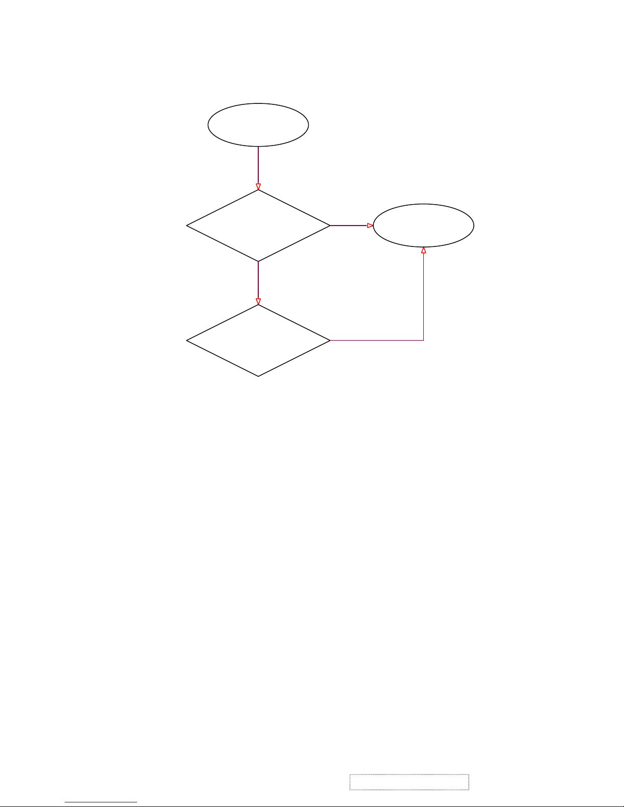
YES
YES
YES
NO
CHECK 5V,3.3VB,
LCD_VCC & 3V3_MCU
START
POWER CKT
(12V,+5V & 3.3V CKT)
POWER CKT
CHECK POWER CKT
END
ViewSonic Corporation
7
Confidential – Do Not Copy
VG900b-1
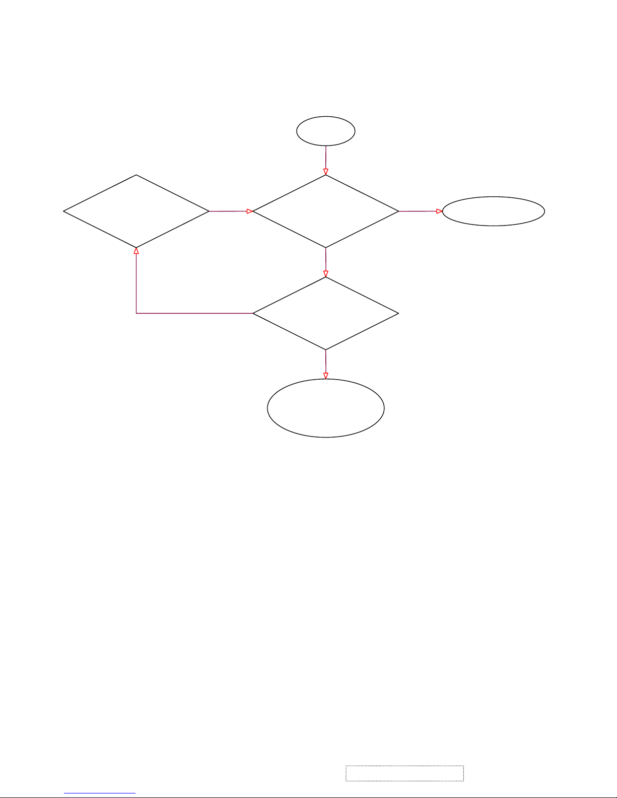
YES
YES
NO
NO
OK
YES
SIGNAL
Check U3 O/P
TO SD1210 CKT
ADC CKT
CHECK I/P R,G & B Video,
HSYNC(pin 30),Coast(pin 31) AND
I2C BUS Signal
START
CHECK MCU CKT(I2C
BUS),D_SUB connector
And U2(74LV14)
ADC CKT
REPLACE U3
& VCLK00
ViewSonic Corporation
8
Confidential – Do Not Copy
VG900b-1
 Loading...