

Page 1

Service Manual
ViewSonic VG930m-3
VA930m-1
Model No. VS11369
19” Color TFT LCD Display
(VG930m-3_VA930m-1_SM Rev. 1a Oct. 2006)
ViewSonic 381 Brea Canyon Road, Walnut, California 91789 USA - (800) 888-8583
Page 2
Copyright
Copyright © 2006 by ViewSonic Corporation. All rights reserved. No part of this publication
may be reproduced, transmitted, transcribed, stored in a retrieval system, or translated into any
language or computer language, in any form or by any means, electronic, mechanical, magnetic,
optical, chemical, manual or otherwise, without the prior written permission of ViewSonic
Corporation.
Disclaimer
ViewSonic makes no representations or warranties, either expressed or implied, with respect to
the contents hereof and specifically disclaims any warranty of merchantability or fitness for any
particular purpose. Further, ViewSonic reserves the right to revise this publication and to make
changes from time to time in the contents hereof without obligation of ViewSonic to notify any
person of such revision or changes.
Trademarks
Optiquest is a registered trademark of ViewSonic Corporation.
ViewSonic is a registered trademark of ViewSonic Corporation.
All other trademarks used within this document are the property of their respective owners.
Revision History
Revision SM Editing Date ECR Number Description of Changes Editor
1a 10/29/2006 Initial Release Jamie Chang
ViewSonic Corporation Confidential - Do Not Copy VG930m-3_VA930m-1
i
Page 3
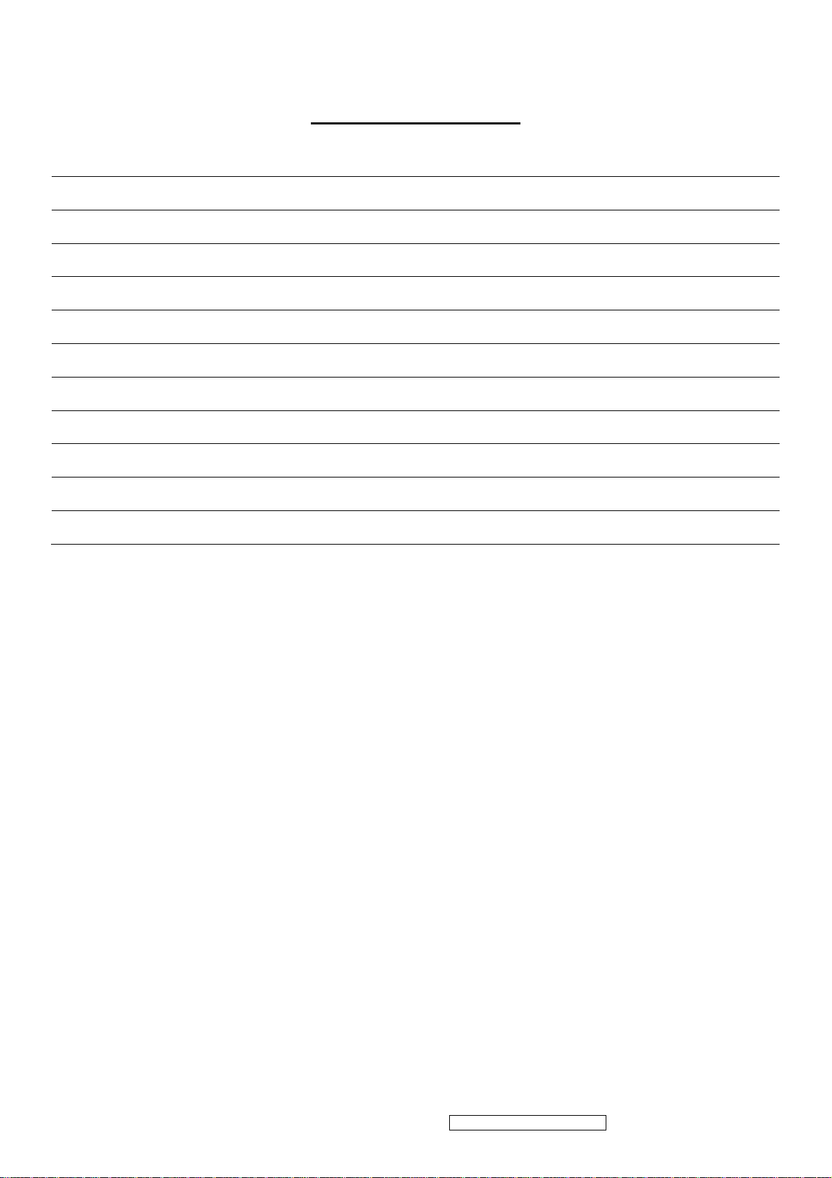
TABLE OF CONTENTS
1. Precautions and Safety Notices 1
2. Specification 4
3. Front Panel Function Control Description 8
4. Circuit Description 14
5. Adjustment Procedure 21
6. Troubleshooting Flow Chart 53
7. Recommended Spare Parts List 61
8. Exploded Diagram and Exploded Parts List 66
9. Block Diagram 69
10. Schematic Diagrams 70
11. PCB Layout Diagrams 75
ViewSonic Corporation Confidential - Do Not Copy VG930m-3_VA930m-1
ii
Page 4

1. Precautions and Safety Notices
1. Please carefully read this manual before operating the device and keep it available for future reference.
2. To avoid the danger of the monitor falling and thereby possibly causing injury and/or serious damage to
the monitor itself, do not place it on unstable cars or desks. Be careful to avoid placing any stress on the
LCD screen during handling.
3. Do not place this monitor in areas that are wet or where water or other liquids may come in contact with it,
such as bathrooms, kitchens, wet floors, near washing machines or by swimming pools.
4. Remove the power plug from the electrical socket before cleaning. No water-containing cleaning agent
should be used to clean the screen, but only cleaning agents formulated specifically for cleaning LCD
screens. Do not put any liquid cleaning agent directly on the screen, but put it on a soft cloth first and then
gently apply the cloth to the screen.
5. In order to guarantee reliable operation and ad equate heat dissipation, do not cover or block vent holes
on the monitor. Do not put the monitor close to heat sources. Do not place the monitor on furniture such
as a bookshelf, unless sufficient ventilation is available.
6. A 3-pin grounding plug is provided for this monitor. In order to guarantee normal operation and safety of
this unit, this plug should be used with a matching grounded power socket.
7. Please follow all warnings and instructions that accompany the monitor.
8. Please pay special attention to power supply overloads, as electrical shock or fire may occur.
9. Do not pl ace anything on the power cord. Do not hang the power cord over an area where people or
objects may pass.
10. In case the monitor is not be used for an extended period, turn off power to avoid the possibility of short
circuits caused by lightning.
11. In order to avoid electrical shock or fire risks, do not insert any object through any openings in the
monitor’s enclosure. Do not allow any liquid to come in contact with the monitor.
12. In case of any abn ormal noise or odor caused by incorrect operation, turn off power immediately and
contact a professional technician. Do not attempt to repair this monitor by yourself, as electrical shock
may occur when opening the back cover or accessing internal components.
13. If any of the following conditions occurs, turn off power and contact a repair service provider:
1) the power cord is damaged or worn;
2) liquid has gotten into the monitor, or the monitor has experienced immersion or wetting;
3) the monitor has fallen;
4) the monitor’s performance shows obvious changes;
5) the monitor fails to work normally when correct procedures are followed. In that case, please make
any adjustments in accordance with instructions supplied with the monitor; do not attempt any
changes to established procedures, as further damage may occur, making successful repair of the
monitor more difficult.
14. In case parts need to be replaced, you must use identical parts or those supplied by our certified
manufacturers. Any other parts used without our authorization may result in electrical shock or fire risk.
ViewSonic Corporation Confidential - Do Not Copy VG930m-3_VA930m-1
1
Page 5
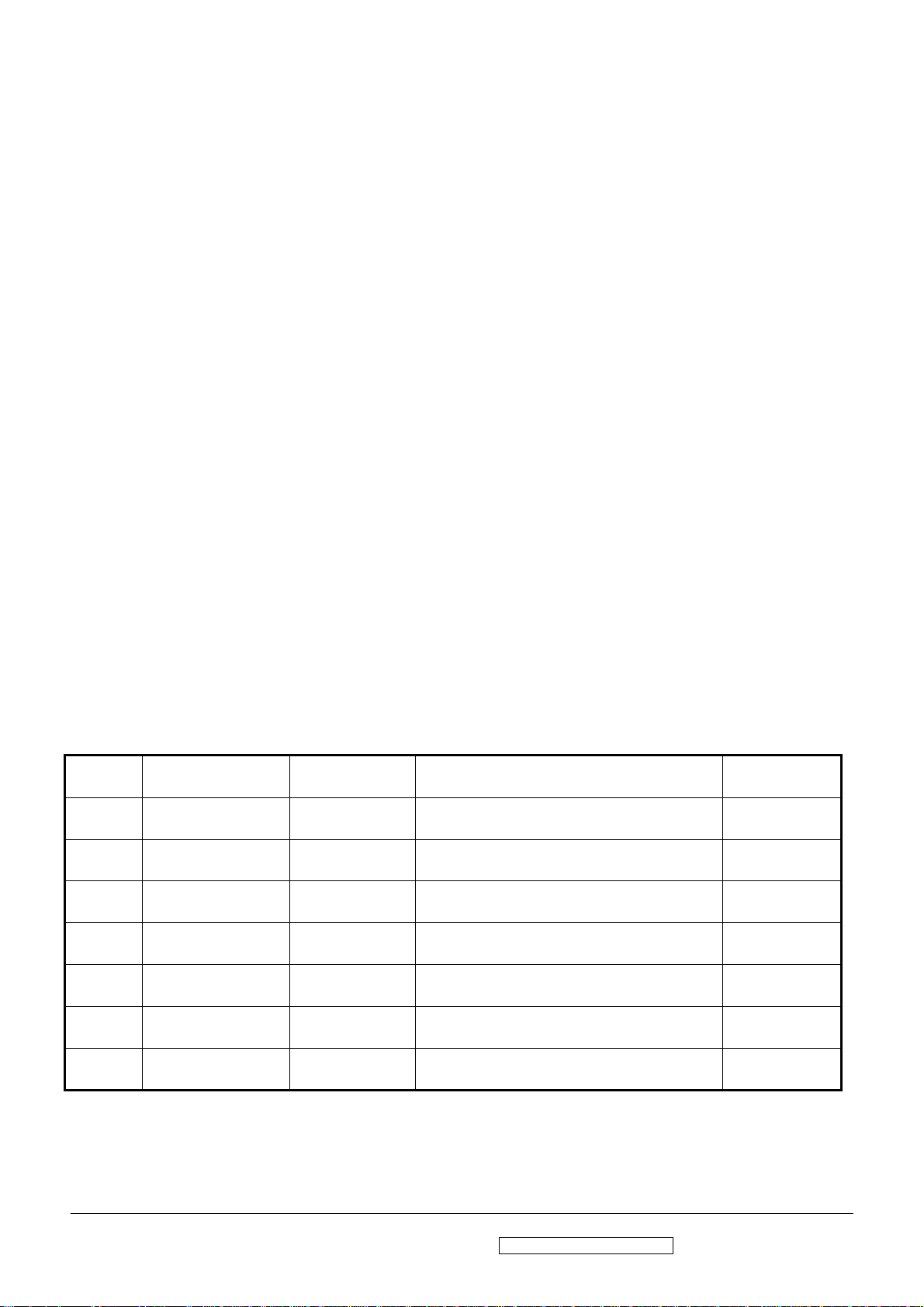
Handing and Placing methods
Correct methods Incorrect methods
Only touch the metal frame of the LCD panel or the front
cover of the monitor, DO not touch the surface of the POL
Take out the monitor with cushions
Surface of the LCD panel is pressed by fingers and that
may cause”mura”
Taking out the monitor by grasping the LCD panel, that
May cause”mura”
ViewSonic Corporation Confidential - Do Not Copy VG930m-3_VA930m-1
2
Page 6
Correct methods Incorrect methods
Place the monitor on a clean and soft foam pad Placing the monitor on a foreign objects, that could
scratch The surface of the "Panel" or cause "mura"
The panel is placed facedown the lap,that may cause
"mura"
ViewSonic Corporation Confidential - Do Not Copy VG930m-3_VA930m-1
3
Page 7
2. Specification
Introduction
The purpose of this document is to define design and performance requirements for MR19V (using
RTD2523B and HSD 19” panel), the 19.X-inch TFT -LCD monitor .
Features
19” SXGA TFT LCD panel
TN (Twist Nematic) Mode
Analog input up to 1280X1024@75Hz
4 dual CCFTs (Cold Cathode Fluorescent Tube)
Supported to 75Hz refresh rate
Supported to 16.2M colors display
Supported VESA-DDC2B plug & play function
Supported VESA-DPMS power management function
LVDS (Low Voltage Differential Signaling) interface (2 pixels/clock)
1 LCD PANEL
st
source)
(1
2 LCD PANEL
nd
(2
source)
Panel:
Size
Pixel Arrange
Glass
Treatment
Contrast Ratio
Viewing Angle
Colors
Luminance
Response
Time
Backlight
Backlight Life
Mercury
Panel:
Size
Pixel Arrange
Glass
Treatment
Contrast Ratio
Viewing Angle
Colors
Luminance
Response
Time
Backlight
Backlight Life
Mercury
CR >=
10
CR >= 5
On/Off
CR >=
10
CR >= 5
On/Off
HSD190ME13-A16
19" Color a-Si TFT Active Matrix 1280x1024 LCD
0.294 mm x 0.294 mm
Anti-Glare, Hard coating (3H)
700 :1
150/135 (degrees; typ)
160/155 (degrees; typ)
16.2 million colors (6+2 bit panel)
300 cd/m2
8 ms
4 CCFL
50000 Hrs (Min)
3 mg per lamp
HSD 190ME13- A10
19" Color a-Si TFT Active Matrix 1280x1024 LCD
0.294 mm x 0.294 mm
Anti-Glare, Hard coating (3H)
700 :1
150/135 (degrees; typ)
N/A (degrees; typ)
16.2 million colors (6+2 bit panel)
300 cd/m2
8 ms
4 CCFL
40000 Hrs (Min)
3 mg per lamp
ViewSonic Corporation Confidential - Do Not Copy VG930m-3_VA930m-1
4
Page 8
LCD PANEL
rd
source)
(3
3 INPUT SIGNAL Video
4 COMPATIBILITY PC
5 RESOLUTION
6 AUDIO Speaker
7 CONNECTORS
Panel:
Size
Pixel Arrange
Glass
Treatment
Contrast Ratio
Viewing Angle
Colors
Luminance
Response
Time
Backlight
Backlight Life
Mercury
Sync
Mac
Recommended
Video
Power
CR >=
10
CR >= 5
On/Off
Analog
Digital
HSD 190ME13-D10
19" Color a-Si TFT Active Matrix 1280x1024 LCD
0.294 mm x 0.294 mm
Anti-Glare, Hard coating (3H)
700 :1
150/140 (degrees; typ)
N/A (degrees; typ)
16.2 million colors (6+2 bit panel)
300 cd/m2
8 ms
4 CCFL
50000 Hrs (Max)/ 40000Hrs @ 7.5mA
3 mg per lamp
RGB Analog (75 ohms, 0.7 / 1.0 Vp-p), DVI
(TMDS, 100 ohms)
Separate Sync / Composite Sync / SOG
Fh = 24 – 82 kHz ; Fv = 50 – 75 Hz
PC Compatibles (from VGA up to 1280x1024 Non
Interlaced)
Power Mac (up to 1280X1024 )
1280x1024 @ 60Hz
640 x 350 @ 70Hz
640 x 400 @ 60, 70Hz
640 x 480 @ 50, 60, 67, 72, 75Hz
720 x 400 @ 70Hz
720 x 480 @ 60Hz
720 x 576 @ 50Hz
800 x 600 @ 50, 56, 60, 72, 75Hz
832 x 624 @ 75Hz
1024 x 768 @ 50, 60, 70, 75Hz
1152 x 864 @ 75Hz
1152 x 870 @ 75Hz
1152 x 900 @ 67Hz
1280 x 720 @ 50, 60Hz
1280 x 768 @ 50, 60, 75Hz
1280 x 960 @ 50, 60, 75Hz
1280 x 1024 @ 50, 60, 75Hz
1.5W x2
DB-15
DVI
Internal Power Adapter, 3-pin plug (CEE22)
8 POWER Voltage
Consumption
9 ERGONOMICS Tilt
Swivel
Height Adjust
Typ/Max
20 ~ -5 degrees
AC 100-240V (Universal); 50-60 Hz
35 W / 40 W
360 degrees
0 ~ 80 mm
ViewSonic Corporation Confidential - Do Not Copy VG930m-3_VA930m-1
5
Page 9
10 CONTROLS
Physical
OSD Function
Key
buttons
Main
Menu
Short cut
key
[PW], [Mute], [ 2 ], [Up], [Dn], [ 1 ]
Auto Image Adjust
Contrast/Brightness
Input Select
Analog, Digital
Color Adjust
sRGB, 9300K, 7500K, 6500K, 5400K, User
Color [R, G, B]
Information
Manual Image Adjust
Horizontal Size, H/V Position, Fine Tune,
Sharpness
Setup Menu
Language Select, Resolution Notice, OSD
Position, OSD Time Out, OSD Background
Memory Recall
[ 1 ] : Main Menu
[ 2 ] : Input Select
[Up] or [Dn] : Contrast / Brightness
[Up] + [Dn] : Recall both of Contrast and
Brightness to default
[ 1 ] + [ 2 ] : Toggle 720x400 and 640x400 mode
[ 1 ] + [Up] + [Dn] : Auto White Balance
[ 1 ] + [Dn] : Power Lock
[ 1 ] + [Up] : OSD Lock
11 BANDWIDTH 135 MHz
12 OPERATING
CONDITION
13 STORAGE /
SHIPPING
CONDITION
14 DIMENSIONS Physical:
Temperature
Humidity
Temperature
Humidity
(W x H x D)
Packing
(W x H x D)
Display
w Stand
Wall
Mount
32°F to 104°F (0°C to 40°C)
10% to 90% (no condensation)
-4°F to 140°F (-20°C to 60°C)°
10% to 90% (no condensation)
428 mm (W) x 479 mm (H) x 230 mm (D)
16.8" (W) x 18.8" (H) x 9.0" (D)
428 mm (W) x399 mm (H) x 68 mm (D)
16.8" (W) x 15.7" (H) x 2.6" (D)
486 mm (W) x 590 mm (H) x 278 mm (D)
19.13" (W) x 23.23" (H) x 10.94" (D)
15 WEIGHT Net
Gross
6.0Kg (13.33 lbs)
7.2Kg (16 lbs)
16 REGULATIONS
UL/CUL, FCC (ICES-003B), CB, CE, TCO'03
TUV/GS, TUV ERGO(covers ISO13406-2 &
MPRII), IRAM, VCCI, GOST-R, HYGIENIC (20
copies), Energy Star, CCC, BSMI, PSB, C-TICK,
SASO, WEEE, RoHS
17 RELIABILITY MTBF 100,000 Hr (Excluding Panel).
18 POWER
SAVING
FUNCTION
"On"
" Active Off"
“Off”
Blue
Amber
Off
Normal
≦1 W
≦1 W
ViewSonic Corporation Confidential - Do Not Copy VG930m-3_VA930m-1
6
Page 10
18 POWER
SAVING
FUNCTION
19 LOGISTICS Container
"On"
" Active Off"
“Off”
Load
(20' / 40')
Pallet Load
UPC Code
Serial Format
EDID Code
Country of
Blue
Amber
Off
Standard
Normal
≦1 W
≦1 W
260 / 624 pieces
26 pieces
76690722783 3
QC2
Byte 10 – 0 x 1E, Byte 11 – 0 x 99
China
origin
20 Wall Mount VESA 100mm x 100mm
21 OTHERS DDC/2B, KENSINGTON MicroSaver Security
Compatible, WorldWide Model.
22 Package
Contents
LCD Display
Power Cable
Video Cable
Audio Cable
Quick Start Guide
ViewSonic Wizard CD-ROM
23 Packaging
Information
Carton -- One piece construction with signal wall, 0.65 Kg
Plastic Handle -- PE-LD, 12g
Poly Foam -- EPS, 207g, 2 pices
Accessory Plastic Bags -- PE-LD, 2g
The PE bag that cover monitor -- PE-LD, 18g
Pallet (M Model ) -- Fumigation wood, 22.5Kg
Pallet (Others) -- Poplar, 22.5Kg
ViewSonic Corporation Confidential - Do Not Copy VG930m-3_VA930m-1
7
Page 11
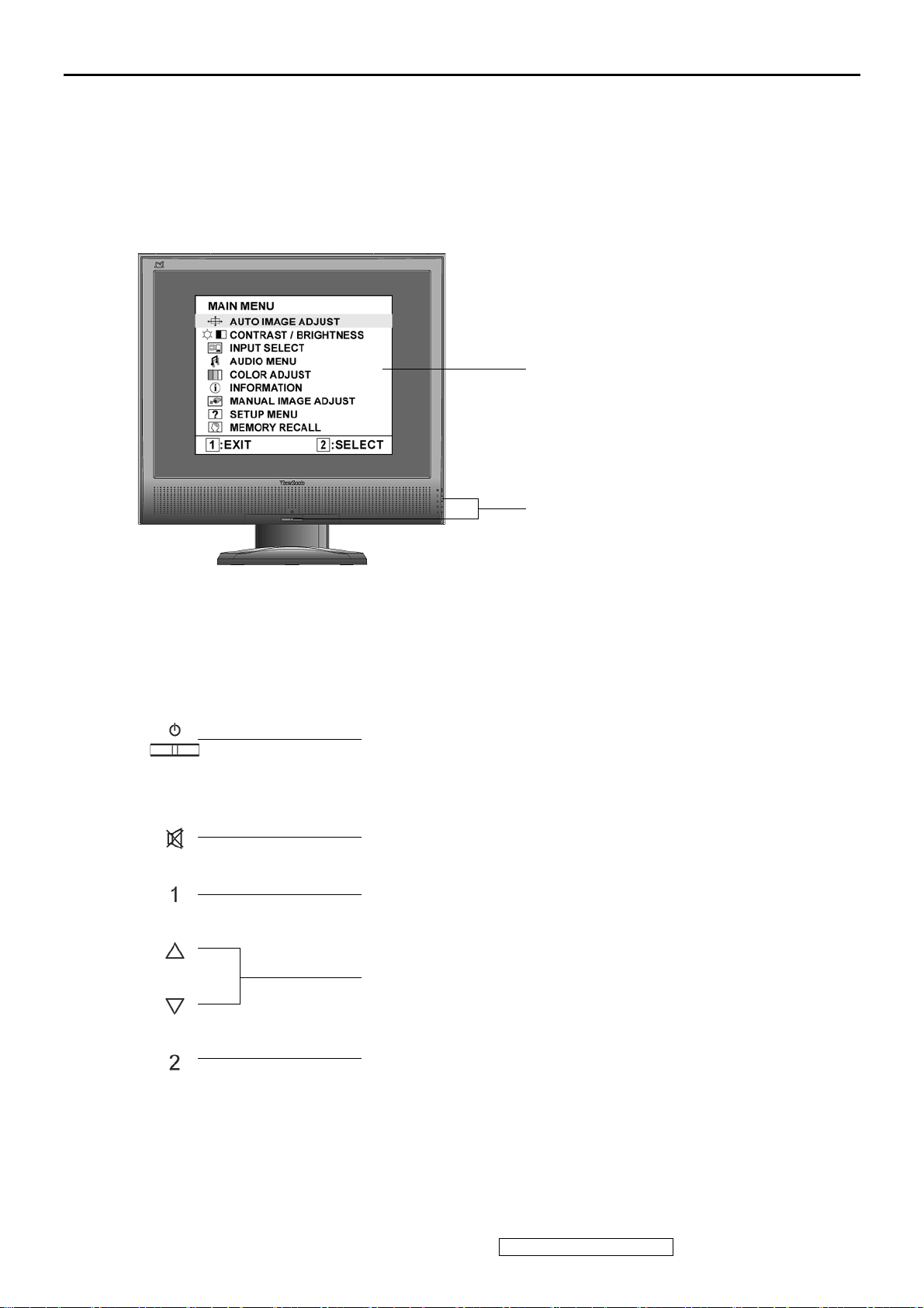
3. Front Panel Function Control Description
Adjusting the Screen Image
Use the buttons on the front control panel to display and adjust the OSD controls which display
on the screen. The OSD controls are explained at the top of the next page and are defined in
“Main Menu Controls” on page 10.
Main Menu
with OSD controls
Front Control Panel
shown below in detail
Standby Power On/Off
Power light
Blue = ON
Orange = Power Saving
Audio Mute button turns the sound off
Displays the Main Menu or exits the control screen and saves
adjustments.
Scrolls through menu options and adjusts the displayed control.
Also a shortcut to display the Contrast adjustment control screen.
Displays the control screen for the highlighted control.
Also toggles between two controls on some screens.
ViewSonic Corporation Confidential - Do Not Copy VG930m-3_VA930m-1
8
Page 12
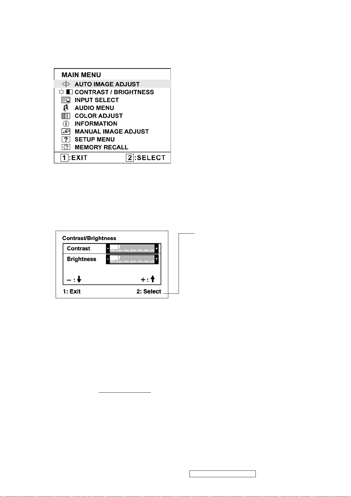
Do the following to adjust the display setting:
1. To display the Main Menu, press button [1].
NOTE: All OSD menus and adjustment screens disappear automatically after about 15
seconds. This is adjustable through the OSD timeout setting in the setup menu.
2. To select a control to adjust, pressSorTto scroll up or down in the Main Menu.
3. After the desired control is selected, press button [2]. A control screen like the one shown
below appears.
The command line at the bottom of the
control screen tells what to do next from
this screen. You can toggle between control
screens, adjust the selected option, or exit
the screen.
4. To adjust the setting, press the up S or down T buttons.
5. To save the adjustments and exit the menu, press button [1] twice.
The following tips may help you optimize your display:
• Adjust the computer's graphics card so that it outputs a 1280 x 1024 @ 60Hz video signal to
the LCD display. (Look for instructions on “changing the refresh rate” in the graphics card's
user guide.)
• If necessary, make small adjustments using H. POSITION and V. POSITION until the
screen image is completely visible
. (The black border around the edge of the screen should
barely touch the illuminated “active area” of the LCD display.)
ViewSonic Corporation Confidential - Do Not Copy VG930m-3_VA930m-1
9
Page 13
Main Menu Controls
Adjust the menu items shown below by using the up S and down T buttons.
Control Explanation
Auto Image Adjust sizes and centers the screen image automatically.
Contrast adjusts the difference between the image background (black level)
and the foreground (white level).
Brightness adjusts background black level of the screen image.
Input Select toggles between inputs if you have more than one computer
connected to the VG930m.
Audio Adjust
Vol ume increases the volume, decreases the volume, and mutes the audio.
Mute temporarily silences audio output.
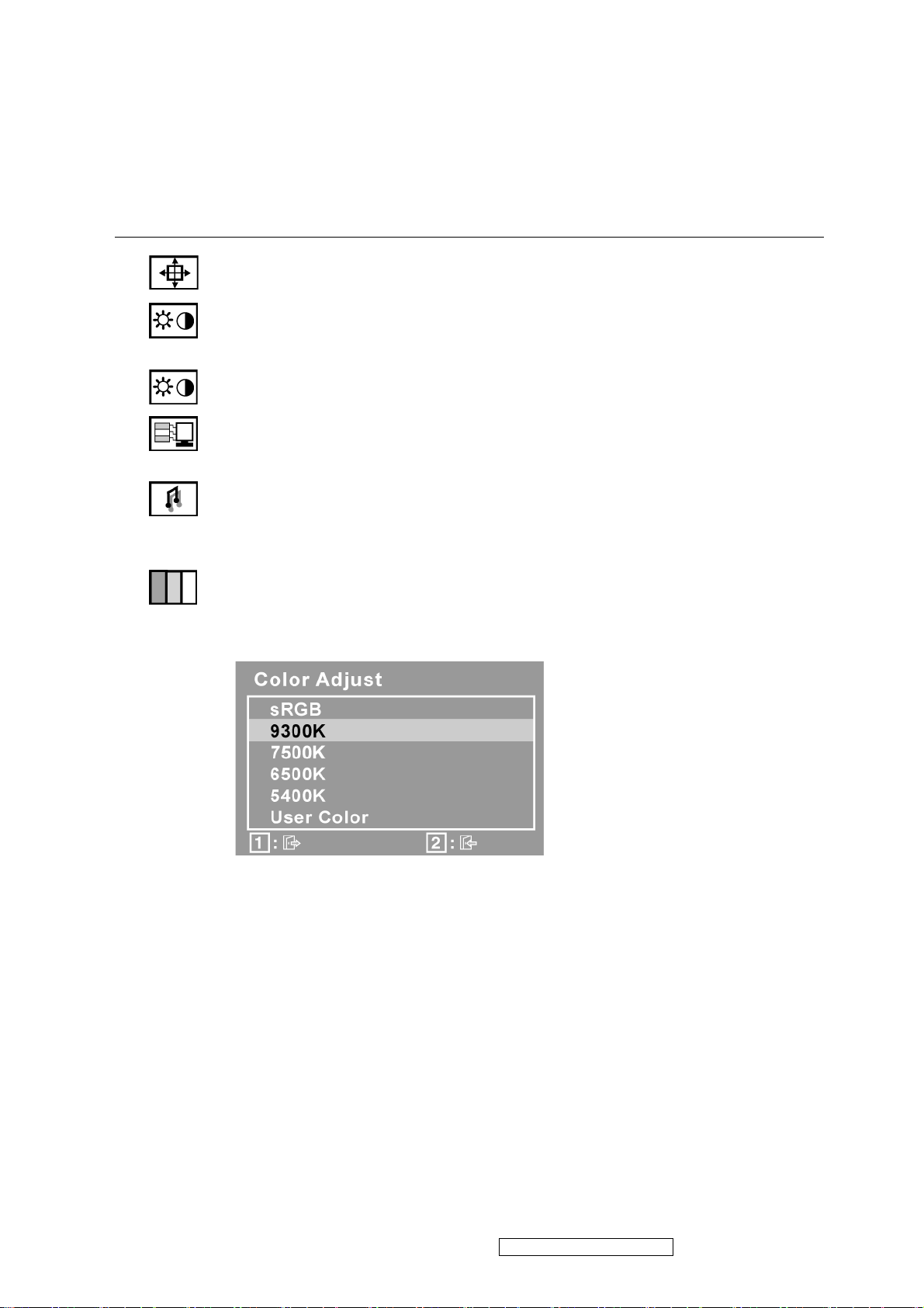
Color Adjust provides several color adjustment modes, including preset color
temperatures and a User Color mode which allows independent adjustment of
red (R), green (G), and blue (B). The factory setting for this product is 6500K
(6500 Kelvin).
sRGB-This is quickly becoming the industry standard for color management,
with support being included in many of the latest applications. Enabling this
setting allows the LCD display to more accurately display colors the way they
were originally intended. Enabling the sRGB setting will cause the Contrast and
Brightness adjustments to be disabled.
9300K-Adds blue to the screen image for cooler white (used in most office
settings with fluorescent lighting).
7500K-Adds blue to the screen image for cooler white (used in most office
settings with fluorescent lighting).
6500K-Adds red to the screen image for warmer white and richer red.
5400K-Adds green to the screen image for a darker color.
ViewSonic Corporation Confidential - Do Not Copy VG930m-3_VA930m-1
10
Page 14

Control Explanation
User Color Individual adjustments for red (R), green (G), and blue (B).
1. To select color (R, G or B) press button [2].
2. To adjust selected color, pressSandT.
Important: If you select RECALL from the Main Menu when the product is
set to a Preset Timing Mode, colors return to the 6500K factory preset.
Information displays the timing mode (video signal input) coming from the
graphics card in the computer, the LCD model number, the serial number, and
the ViewSonic® website URL. See your graphics card’s user guide for
instructions on changing the resolution and refresh rate (vertical frequency).
NOTE: VESA 1280 x 1024 @ 60Hz (recommended) means that the resolution
is 1280 x 1024 and the refresh rate is 60 Hertz.
Manual Image Adjust
H. Size (Horizontal Size) adjusts the width of the screen image.
H./V. Position (Horizontal/Vertical Position) moves the screen image left or
right and up or down.
ViewSonic Corporation Confidential - Do Not Copy VG930m-3_VA930m-1
11
Page 15
Control Explanation
Fine Tune sharpens the focus by aligning text and/or graphics with pixel
boundaries.
NOTE: Try Auto Image Adjust first.
Sharpness adjusts the clarity and focus of the screen image.
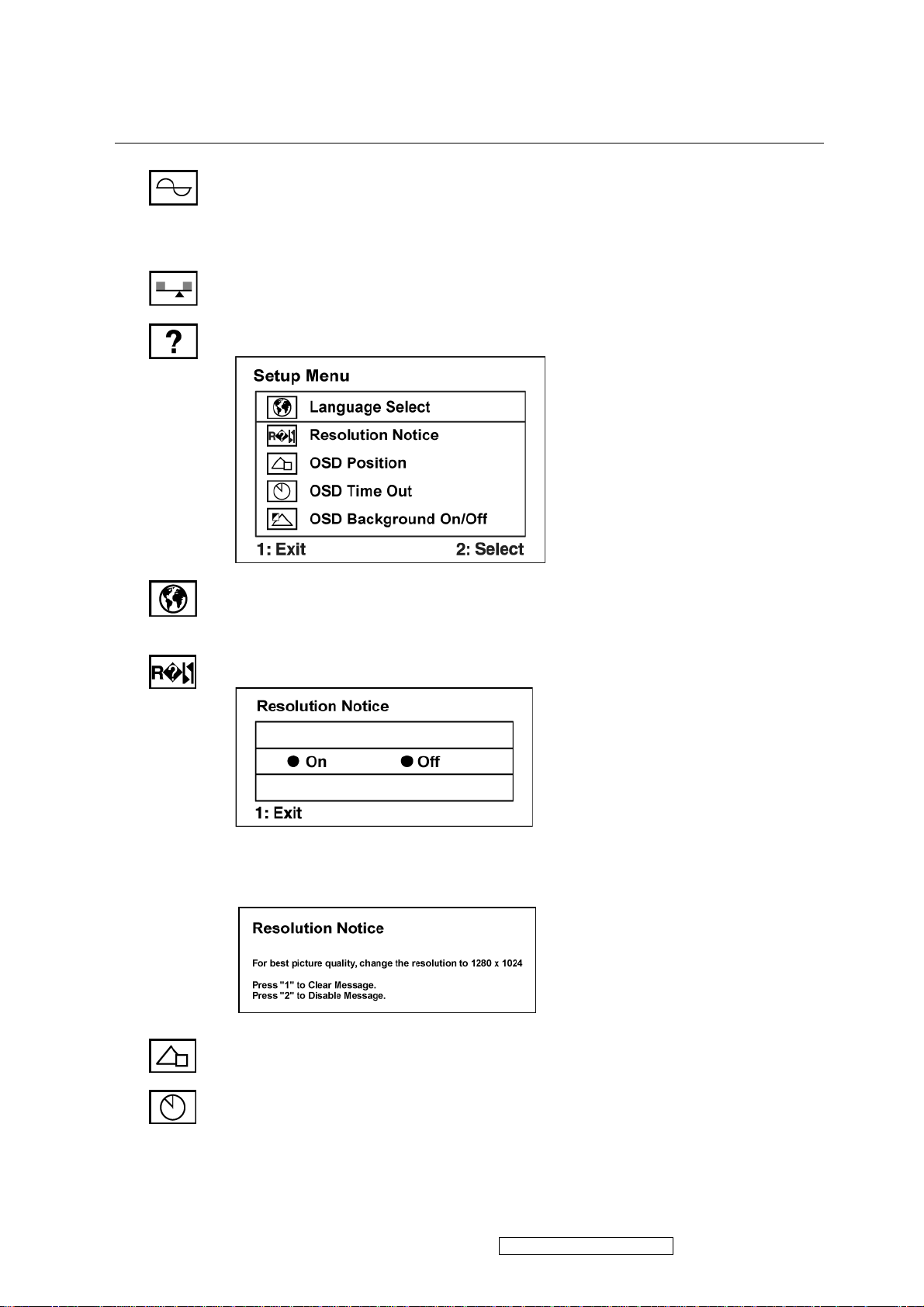
Setup Menu displays the menu shown below:
Language Select allows the user to choose the language used in the menus and
control screens.
Resolution Notice allows the user to enable or disable this notice.
If you enable the Resolution Notice shown above and your computer is set at a
resolution other than 1280 x 1024, the following screen appears.
OSD Position allows the user to move the OSD menus and control screens.
OSD Timeout sets the length of time the OSD screen is displayed. For example,
with a “30 second” setting, if a control is not pushed within 30 seconds, the
display screen disappears.
ViewSonic Corporation Confidential - Do Not Copy VG930m-3_VA930m-1
12
Page 16

Control Explanation
OSD Background allows the user to turn the OSD background On or Off.
Memory Recall returns the adjustments back to factory settings if the display is
operating in a factory Preset Timing Mode listed in the Specifications of this
manual.
ViewSonic Corporation Confidential - Do Not Copy VG930m-3_VA930m-1
13
Page 17
4. Circuit Description
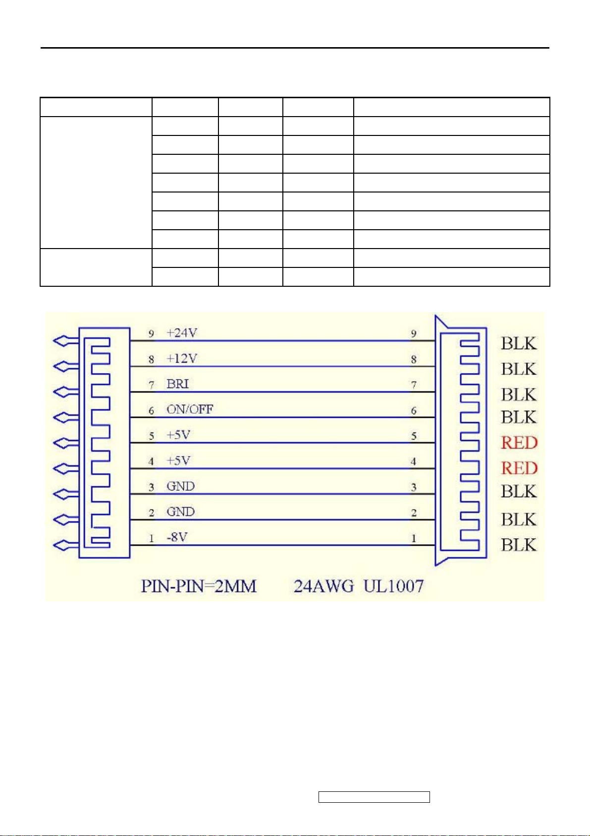
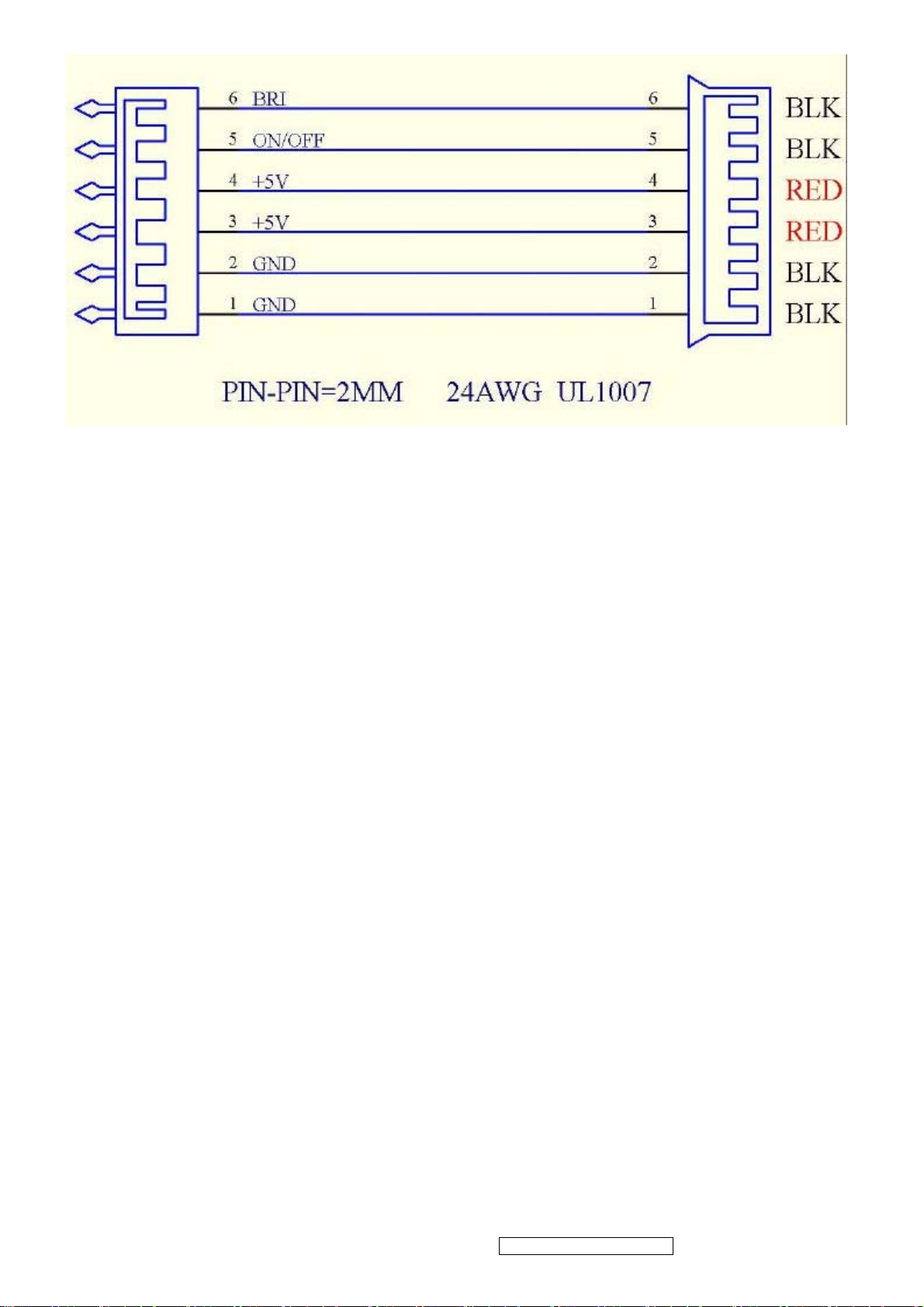
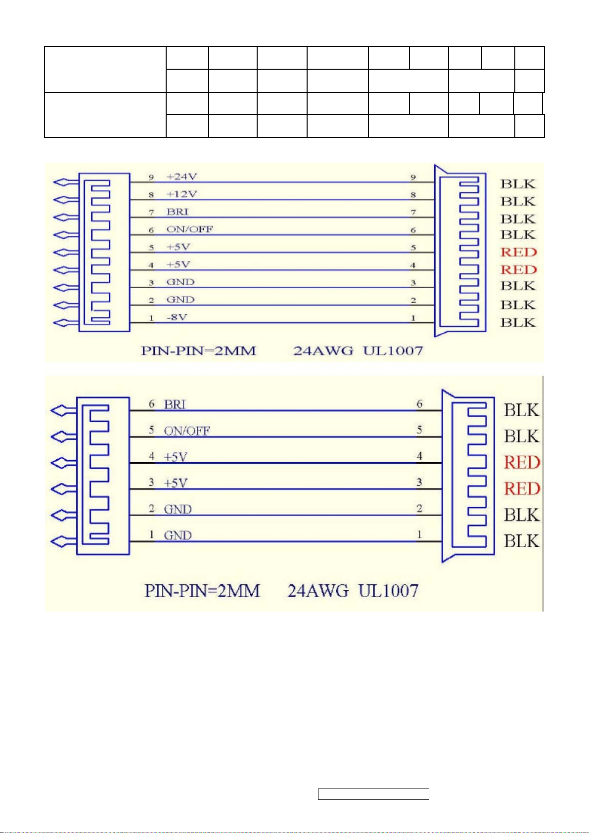
4.2 Power Board
Electric Spec :
Connection 9Pin NO. 6Pin NO. Symbol Description
9 NC DC-Output 24.0±10%Vdc / 50mA (Optional)
8 NC DC-Output 12±10%Vdc / 200mA (Optional)
7 6 BL-Adj Luminance Control ( 0Vdc~3.3Vdc )
CON802 6 5 ON/OFF ON : 3.3Vdc or 5.0Vdc ; OFF : 0V
4. 5 3. 4 DC-Output 5.0±5%Vdc / 2500mA
2. 3 1. 2 GND GND
1 NC DC-Output -8±10%Vdc / 100mA(Optional)
CON901~CON904
1 1 H.V High Voltage
2 2 Return Return Pin
ViewSonic Corporation Confidential - Do Not Copy VG930m-3_VA930m-1
14
Page 18
ELECTRIC TEST
1. POWER TEST :
1-1 . OUTPUT VOLTAGE TEST : Output 24V connect 50mA, CON801 Input
1-2 . HI-POT TEST :
1) Test Requirements – Input Voltage : 3.0KVdc
– Measurement Time : 3sec
– Temperature : 25 ± 5 ℃℃
2) A method of measurement : Injection voltage between Utility (Line and Neutral short) and output line (short
between + and - )
3) Criterion for Judging : PASS
1-3 . SHORT TEST PROTECT :
24Vdc SHORT to GND , POWER PROTECT .
12Vdc SHORT to GND , POWER PROTECT .
5Vdc SHORT to GND , POWER PROTECT .
-8Vdc SHORT to GND , POWER PROTECT .
1-4 . LOW POWER CONSUMPTION: Input 240Vac/50Hz Output NO LOAD , Power Consumption≦0.5W . 1-5 .
GROUND TEST :
1) Test Requirements – Input Current : 25A
– Measurement Time : 3sec
– Temperature : 25℃± 5℃
2) A method of measurement : Injection current between Utility F.G. (inlet socket F.G.) and output ground (heat
sink)
3) Criterion for Judging : ≦Resistor 100mΩ
ViewSonic Corporation Confidential - Do Not Copy VG930m-3_VA930m-1
15
Page 19
1-6 . Insulation Resistance
1) Test Requirements – Input Voltage : 500Vdc
– Temperature : 25℃± 5℃
2) A method of measurement : Test between Utility (live and neutral short) and output line (+ and - short).
(insulation resistance test)
3) Criterion for Judging : Insulation resistance ≧ 100MΩ 2. INVERTER TEST: 2-1. OPEN LAMP PROTECT
TEST :
Test Condition : ON/OFF PIN=3.3Vdc or 5.0Vdc , BL-Adj PIN=3.3Vdc or 5.0Vdc . Result : CN901~CN904
OPEN , INVERTER TURN ON CONTINUE 1~2 SECONDS SHUT DOWN .
2-2. KICK-OFF VOLTAGE TEST : Test Condition : ON/OFF PIN=3.3Vdc or 5.0Vdc , BL-Adj PIN=3.3Vdc or 5.0Vdc .
Result :
CN901~CN903 TEST CN904 H.V PIN Output Voltage≧1.5KV rms.
CN902~CN904 CONNECT TEST CN901 H.V PIN Output Voltage≧1.5KV rms .
CN903 . CN904 . CN901 CONNECT TEST CN902 H.V PIN Output Voltage≧ 1.5KV rms .
CN901 . CN902 . CN904 CONNECT TEST CN903 H.V PIN Output Voltage≧ 1.5KV rms .
2-3 . OUTPUT CURRENT TEST :
CN802 Pin
24V GND
22~28Vdc 3.3Vdc
22~28Vdc 0Vdc
22~28Vdc
Test Condition
CN802
CN802 Pin
BL-Adj
ON/OFF
PIN
3.3Vdc or
5.0Vdc
3.3Vdc or
5.0Vdc
0Vdc or
0Vdc
3.3Vdc
17'' or 19''
PANEL
17'' or 19''
PANEL
17'' or 19''
PANEL
Result
CN901~CN904
6.5±0.5mA /
50±5KHz
7.0±0.5mA /
50±5KHz 7.5±0.5mA
/ 50±5KHz MEET L
NEED
Jumper
3.5±0.5mA
NO Output
ViewSonic Corporation Confidential - Do Not Copy VG930m-3_VA930m-1
16
Page 20
OLD TEST
CN801 Input 100~240Vac , CN802 BL-Adj Pin CONNECT 3.3Vdc , CN802 ON/OFF Pin CONNECT
3.3Vdc OR 5.0Vdc ,
ATTENTION
1. WHEN OPERATION, WEAR STATIC ELECTRICITY RING AND KEEP GND.
2. TO PREVENT A SHORT CIRCUIT.
3. CON801 / C809 / C802 / C803 / BD801/ Q801 / T801/T802/T901/ THESE LARGE VOLUM MUST WEIGHT
A LOT
4.3 Scaler Board
17 '' and 19 '' LCD MONITOR
WORK ENVIROMENT 1. WORK ENVIROMENT TEMPERATURE : 0 ℃ ∼40 ℃2. WORK ENVIROMENT
humidity : 30% ∼ 85% RH . 3. STORE ENVIROMENT TEMPERATURE :-25℃∼+85℃4. STORE
ENVIROMENT humidity : 30% ∼ 90% RH
INPUT REQUIREMENT: AC Input Voltage :100Vac ~240Vac / 50~60Hz
SPEC :
NO List CH 1 CH 2 CH 3 CH4
1 Channel Name -8V(Optional) +5V +12V(Optional) +24V
OUTPUT VOLTAGE
2
SPEC
1. 900mA for
3 OUPUT CURRENT SPEC 50mA 2500mA 200mA
PANEL(Optional)
LOWEST WORK
4
CURRENT
WAITTING 5V
5 Load=50~80mA , 7V ~ 12V 4.75V ~ 5.25V 11.5V ~ 16V 22.6V~30V
6 Ripple & Noise 200mVp-p 100mVp-p 300mVp-p 300mVp-p
-8V±10% +5V±5% +12V(11.5~13.5V) +24V±10%
Inverter 2. 50mA for
SIP
10mA 400mA 50mA 10mA
WAITTING MERIT : AC INPUT 240Vac , NO Load
(L=80mm) INTRODUCTION :
ViewSonic Corporation Confidential - Do Not Copy VG930m-3_VA930m-1
17
Page 21
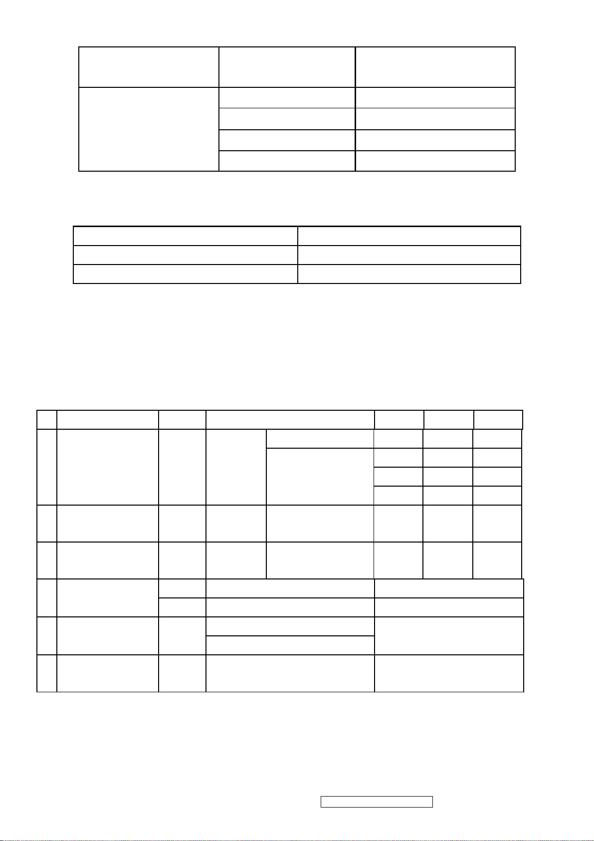
PIN NO. FOR RSDS
PANEL SPEC 24V 12V ADJ On/Off 5V GND -8V
PIN NO. FOR LVDS
PANEL SPEC NC NC ADJ On/Off 5V GND NC
9 8 7 6 5 4 3 2 1
NC NC 6 5 4 3 2 1 NC
OUTPUT VOLTAGE RISE TIME AC INPUT 90 Vac ~264Vac, <100mS .
AC ELECTRICITY TIME DELAY WHEN AC INPUT , OUTPUT VOLTAGE SHOULD WITHIN 1.5S .
SURGE ELECTRI CURRENT AC INPUT 240Vac .
PROTECT FOR SHORT CIRCUIT
PROTECT FOR OVER-CURRENT
ViewSonic Corporation Confidential - Do Not Copy VG930m-3_VA930m-1
18
Page 22
Input Voltage(V) Output(V) Output Current limits (A)
90Vac~264Vac +12 <4
47~63Hz
PROTECT FOR OVER-CURRENT
Output Voltage (V) Voltage limit (V)
24 38
12 20
Hi-POT TEST 3KVac / 3Sec
INSULATION IMPEDANCE INPUT 500Vdc , INSULATION IMPEDANCE > 100M Ohm
GND TEST INPUT 25Adc / 3 Sec , RESISTANCE CONNECT GROUNS <100m Ohm
INVERTER INTRODUCTION : 17 '' and 19 '' PANEL LCD MONITOR
1) 1 .-4 lamp type of 17 '' and 19 '' PANEL
+24 <2A
+5 <6
-8 <4
2) 2. SPEC REQUIREMENT
Items Sign. Condition Min Typ Max
BL-ADJ=0V 3.0 3.5 4.0
6.0 6.5 7.5
1 Output Current (mA) Lout1.2 Vin=24V
7.0 7.5 8.0
Output Voltage
2
(Vrms)
Lamp Frequency
3
(kHz)
4 On/Off Control
Dim Adjust (Lamp
5
Current Control)
Kick-Off
6
Voltage(Vrms)
Vin=24V BL-ADJ=3.3V 560 660 760
f Vin=24V BL-ADJ =3.3V 45 50 55
On Vin=24V, On/Off=3.3V or 5V Normal Operation
Off Vin=24V, On/Off=0V Shunt-down (Lamp off)
BL-ADJ = 3.3V, Max Current
BL-ADJ
BL-ADJ = 0V, Min Current
Vk-off Kick-Off More than 1500
BL-ADJ=3.3V
6.5 7.0 7.5
0V ~ 3.3V
ViewSonic Corporation Confidential - Do Not Copy VG930m-3_VA930m-1
19
Page 23
4.4 EDID Data
[DDC#1]
00 FF FF FF FF FF FF 00 5A 63 1E 99 01 01 01 01
01 10 01 03 80 26 1E 78 2E C5 56 A4 54 4A 9D 24
14 4F 54 BF EF 80 81 80 81 40 71 4F 31 0A 01 01
01 01 01 01 01 01 30 2A 00 98 51 00 2A 40 30 70
13 00 78 2D 11 00 00 1E 00 00 00 FF 00 51 43 32
30 36 30 31 30 30 30 30 31 0A 00 00 00 FD 00 32
4B 1E 52 0E 00 0A 20 20 20 20 20 20 00 00 00 FC
00 56 47 39 33 30 6D 2D 33 0A 20 20 20 20 00 3E
[DDC#1]
00 FF FF FF FF FF FF 00 5A 63 1E 99 01 01 01 01
01 10 01 03 0E 26 1E 78 2E C5 56 A4 54 4A 9D 24
14 4F 54 BF EF 80 81 80 81 40 71 4F 01 01 01 01
01 01 01 01 01 01 30 2A 00 98 51 00 2A 40 30 70
13 00 78 2D 11 00 00 1E 00 00 00 FF 00 51 43 32
30 36 30 31 30 30 30 30 31 0A 00 00 00 FD 00 32
4B 1E 52 0E 00 0A 20 20 20 20 20 20 00 00 00 FC
00 56 47 39 33 30 6D 2D 33 0A 20 20 20 20 00 E9
4.5 Interface
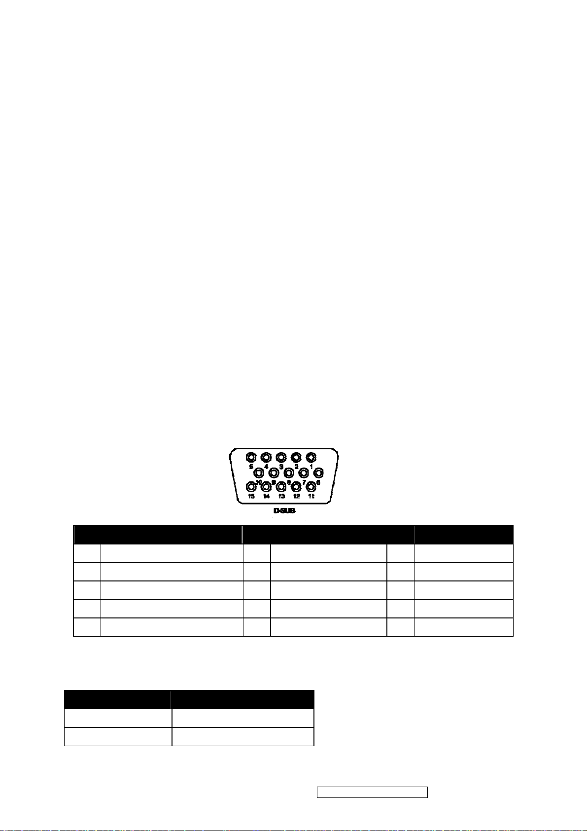
4.5.1Pin Assignment
D-SUB connector:CN2
Pin Input Signal Pin Input Signal Pin Input Signal
1 Red video 6 Red Video Ground 11 Open
2 GreenVideo/Sync on Green 7 Green Video Ground 12 Data line (SDA)*
3 Blue Video 8 Blue Video Ground 13 H-Sync
4 Ground 9 +5V (for cable detect) 14 V-Sync
5 Ground 10 Connector detector 15 Clock line (SCL)*
*Compliant to VESA DDC.
4.5.2Audio Input (line-in)
Item Specifications
Input Voltage 1 Vrms
Output Power 1 W dual channel output
ViewSonic Corporation Confidential - Do Not Copy VG930m-3_VA930m-1
20
Page 24
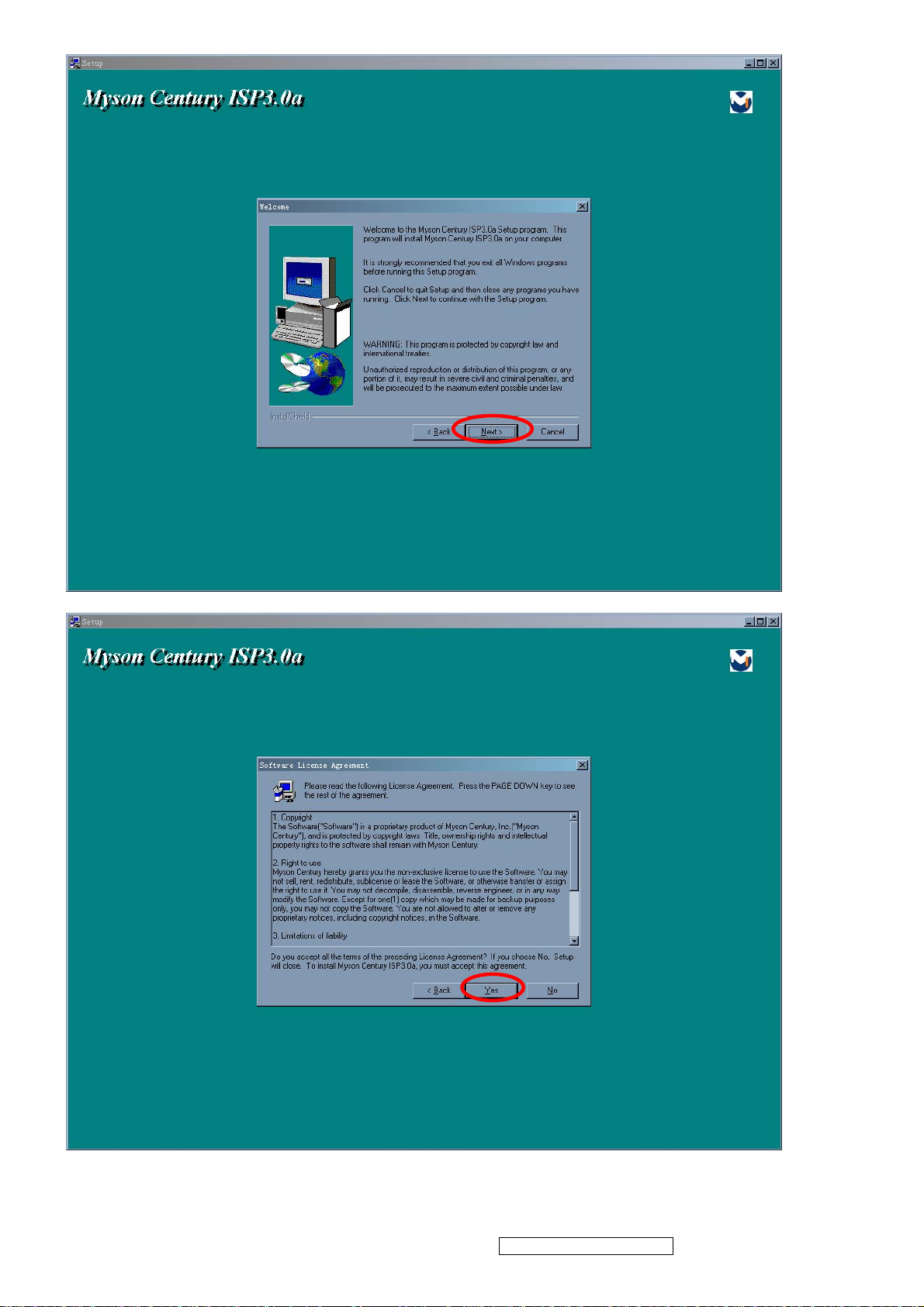
5. Adjusting Procedure
Setup Procedure.
ViewSonic Corporation Confidential - Do Not Copy VG930m-3_VA930m-1
21
Page 25
ViewSonic Corporation Confidential - Do Not Copy VG930m-3_VA930m-1
22
Page 26
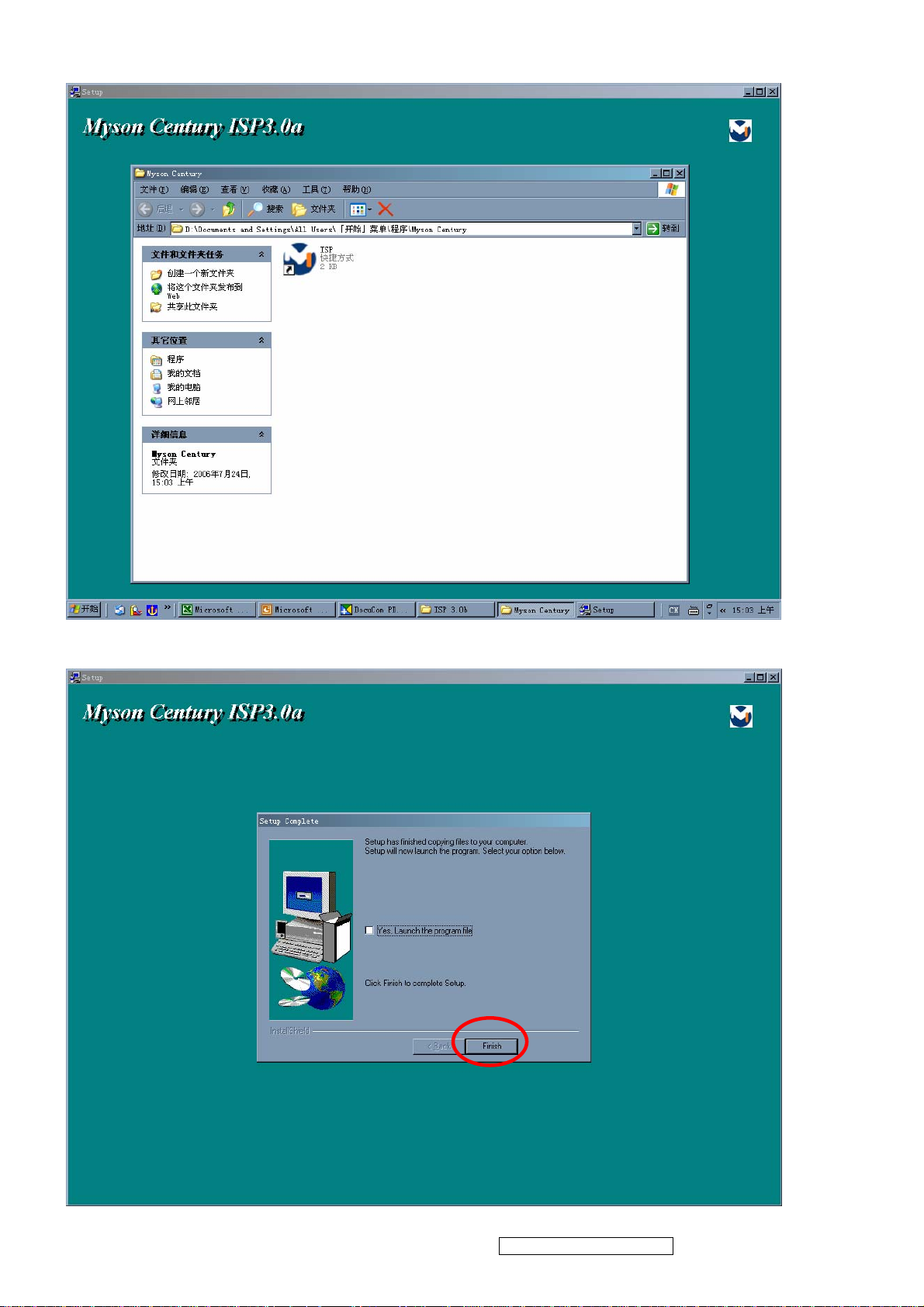
Installation will create a icon for ISP application in “START MENU”\PROGRAM
Press “finish” button exit setup
ViewSonic Corporation Confidential - Do Not Copy VG930m-3_VA930m-1
23
Page 27

Firmware Update Procedure
17. 1 The monitor’s firmware update for VG930 have two method.
1.1. Download the MCU IC by the fire machine. This procedure is finished in SMT .
1.2. ISP Method. When the monitor’s BIOS isn’t exist or firmware isn’t final program, this method Is worked by
ISP Cord with monitor
17.2.1 Equipment Needed
- USB cable for print port *1
- VGA cable*1
- LPT cable (25pin)*1
- AC power cable*1
- ISP fire cord ( the fixture is made in TE ) for firmware upgrade*1
- Power adapter for firmware upgrade (this adapter is made in TE)*1
- A computer with WindowsXP
- VG930 monitor ( no firmware)
- a additional monitor for system display
- ISP & ISP3.0 program
2. VG930 monitor upgrade firmware by ISP Cord.
NOTE:
The fixture for firmware upgrade provide two different method to fire. Please check you monitor’s
Main board, refer to MCU-RSIC type and choose the method.
Below form appear the relation between the method and the MCU-RSIC type
METHOD MCU ASIC JUMPER
A MYSON M-STAR & NOVATEK PIN2-3 CLOSED
B OTHER REALTEK PIN1-2 CLOSED
ViewSonic Corporation Confidential - Do Not Copy VG930m-3_VA930m-1
24
Page 28

LPT PORT
LPT Cable
TEST PC
Fixture ISP_CORD Fixture POWER_ADAPTER
AC power Cable
ISP3.0 SOFT
VGA Cable
USB FOR PRINT
ViewSonic Corporation Confidential - Do Not Copy VG930m-3_VA930m-1
25
Page 29

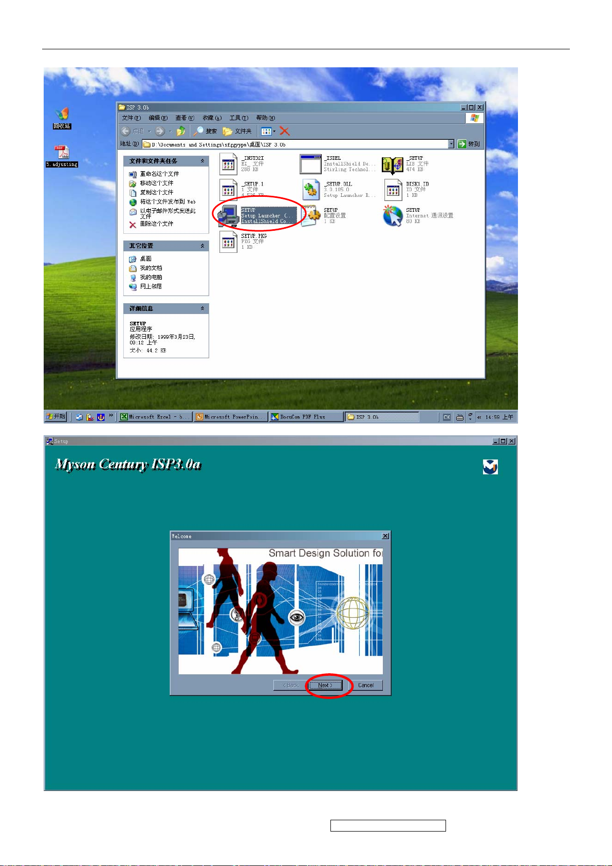
17.2.4. Firmware Upgrade Procedure
Step17.2.4.1 connect all kinds of cable with PC ok, turn on the computer and open the ISP.EXE
Isp.exe
Step17.2.4.2 The “ISP.EXE” application is running as the below picture. Press the “create security file” Button
to create a security file
ViewSonic Corporation Confidential - Do Not Copy VG930m-3_VA930m-1
26
Page 30

Step17.2.4.3 In this dialog box. at first , key in or press the “up toward” key to change the command number to
4. second, key “94,94,AC,CA,53”in the ISP slave add. Slave b add. Command1.Command2. command3.table,
the below form showed the data list
Setp17.2.4.4 Select MTV Type in the “MTV type” list . VG930 monitor must be choose the
“MTV512M64”option
ViewSonic Corporation Confidential - Do Not Copy VG930m-3_VA930m-1
27
Page 31

Step17.2.4.5 Load the MCU file to fire. Click the “load MCU file” button to entry to interface of setting
current path and select the BIOS file in the disk
2. Entry to interface of selecting file
3. Open file and load file ok
4.Check the BIOS checksum
Step17.2.4.6 Select the program upgrade made must be select “autorun” mode at this .
ViewSonic Corporation Confidential - Do Not Copy VG930m-3_VA930m-1
28
Page 32

Step17.2.4.7 click the “run” button to upgrade monitor’s firmware.
Step17.2.4.8 Firmware is upgraded ok .please check the data of “S/W CRC” “H/W CRC”“CHECKSUM” “MAX
ADDR” .
ViewSonic Corporation Confidential - Do Not Copy VG930m-3_VA930m-1
29
Page 33

EDID
Note: After having assembled the monitor, please do the DDC Key In procedure. If you find the DDC does not
conform to the monitor, please do the DDC Key In again .
17.3. 1 Equipment Needed
- VG730 Series Monitor
- RS232-VGA Cable*1
- RS232-DVI Cable*1
- AC POWER Cable*1
- TEST PC with WindowsXP
- Display Data Channel (D8330 DDC Card) to plug PC_PCI _Slot
- DYNACOLOR DDC Tester System software
- Barcode Scanner *1
- AC POWER Source
- one additional monitor for Test System displaying
DDC CORD Barcode Scanner
PC
RS232-VGA Cable AC POWER Cable RS232-DVI Cable
DDC TESTER SOFT
D8330 CORD
ViewSonic Corporation Confidential - Do Not Copy VG930m-3_VA930m-1
30
Page 34

17.3.2 Setup Procedure
17.3.2.1 Open computer’s box cover, pluged D8330 CORD in PCI slot, closed cover and connect AC power
, Monitor, Barcode Scanner, Mouse, Keyboard with PC Connect RS232-VGA cable to DDC RS232 OUT port
of PC ( if you do DDC Key In for D_SUB )
17.3.2.2 Connect RS232-DVI cable to DDC RS232 OUT port of PC ( if you do DDC key In for D_DVI ).
NOTE:
Barcode Scanner and Keyboard pluged in Keyboard port of computer together
DDC RS232 output port
RS232-VGA & RS232-DVI coble
17.3.2.3 DDC TESTER SYSTEM SOFT SETUP( from setup file )
NOTE:
Before install DDC Tester System Soft , please checking the D8330 CORD is plugged Or the DDC Tester
application could’t be run .
17.3.2.3.1 Install DDC Tester System by selecting and checking setup.exe icon. Press “YES” or “NEXT”
Buttons until the installation is completed.
ViewSonic Corporation Confidential - Do Not Copy VG930m-3_VA930m-1
31
Page 35

ViewSonic Corporation Confidential - Do Not Copy VG930m-3_VA930m-1
32
Page 36

ViewSonic Corporation Confidential - Do Not Copy VG930m-3_VA930m-1
33
Page 37

DDC Key In Procedure
Step 1 select and execute DDC Key In program ( winDDC.exe icon on desktop )
ViewSonic Corporation Confidential - Do Not Copy VG930m-3_VA930m-1
34
Page 38

Step 2 Load DDC source file
Step2.1 Choose “File “menu, click “Model Edit “and entry” model edit “ialog box
Step2.2 Press “Brower” button , set current DDC_LOAD_FILE working path
ViewSonic Corporation Confidential - Do Not Copy VG930m-3_VA930m-1
35
Page 39

Step2.3 click “working Model”, select Model in list box
Step2.4 Return to main windows of “ WinDDC.exe”. And choose DDC file in “work Model” down-list box
ViewSonic Corporation Confidential - Do Not Copy VG930m-3_VA930m-1
36
Page 40

Step3 Double click the “input barcode” icon at the toolbar, Key in the serial number or Use Barcode Scanner to
scan the barcode of the monitor. and press the “enter” key .
Step 4 The successful picture is as follows. The EDID data Description will appear the bottom of windows
The EDID Data will appear the top of windows.
ViewSonic Corporation Confidential - Do Not Copy VG930m-3_VA930m-1
37
Page 41

Step 5 Checking Methods
Step5.2 open up the “my computer” attribute dialog box, select the “hardware” option, open up “drive
management”. Below the monitor catalog, uninstall the monitor.
Step5.3 Scan the hardware change ,until system find the new monitor driver
ViewSonic Corporation Confidential - Do Not Copy VG930m-3_VA930m-1
38
Page 42

Step5.4 Select and click the “EDIDW2K.EXE “file, the EDID information will show on the screen
Setp5.5 Ckeck the DDC
ViewSonic Corporation Confidential - Do Not Copy VG930m-3_VA930m-1
39
Page 43

Packing For Shipping And Disassembly Procedure
ViewSonic Corporation Confidential - Do Not Copy VG930m-3_VA930m-1
40
Page 44

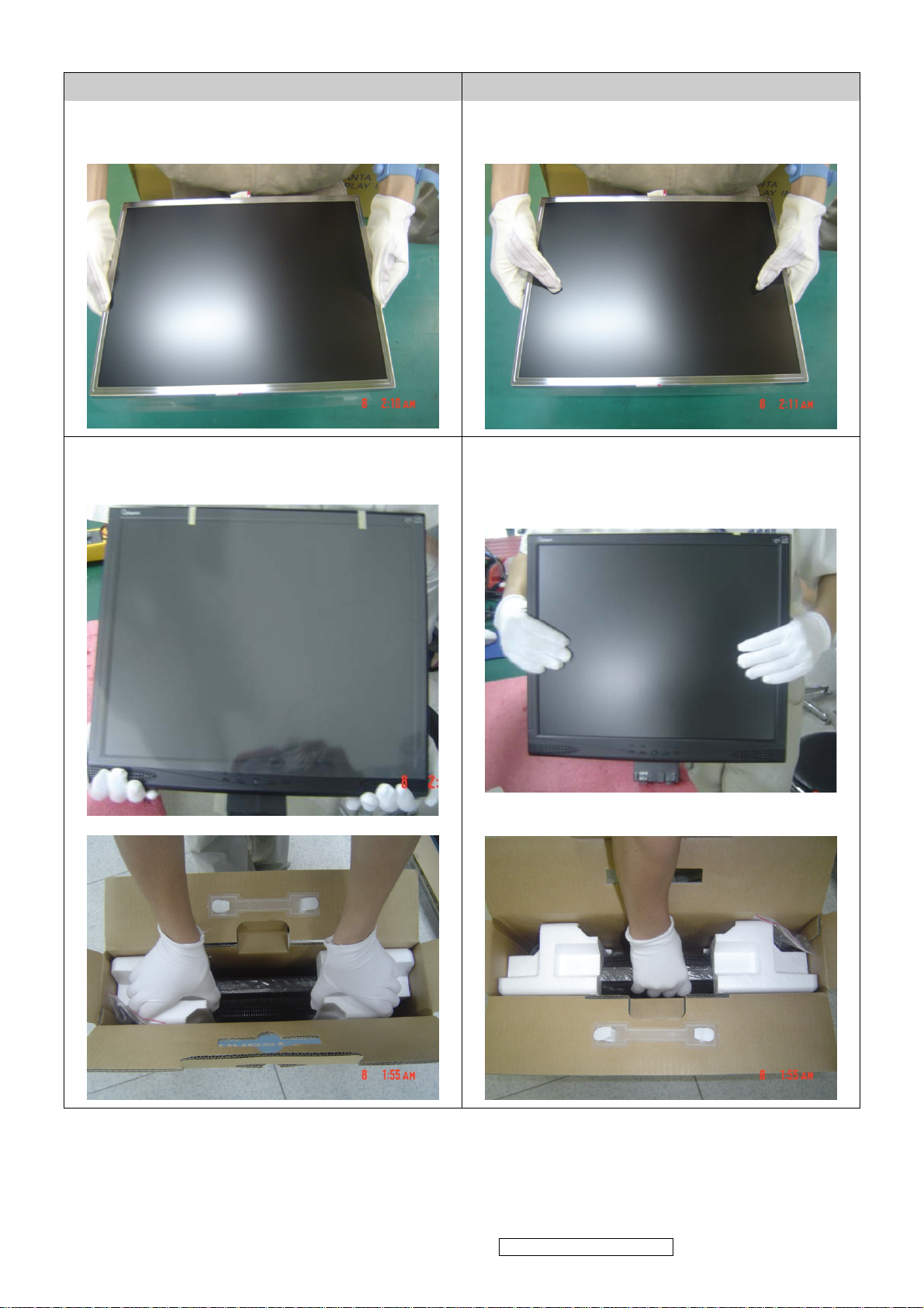
Disassembly Procedure
1. (Take down the cover of bracket)
2. (4PCS)(Take down fixed screws on hinge)
ViewSonic Corporation Confidential - Do Not Copy VG930m-3_VA930m-1
41
Page 45

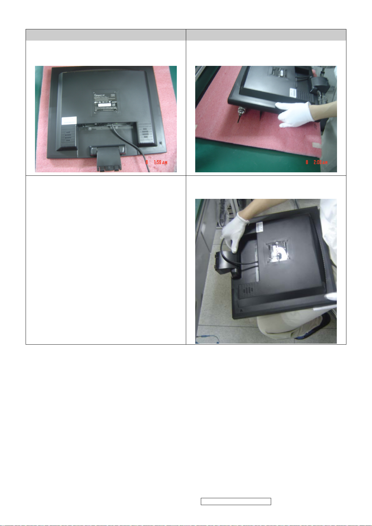
3 (3PCS)(Take down the rear cover screws)
4. (Take apart the rear cover)
ViewSonic Corporation Confidential - Do Not Copy VG930m-3_VA930m-1
42
Page 46

5. (Take down the speaker for right & left)
6. (Take down fixed wire of speaker; Unplug the wire of speaker)
7. (Take down fixed ALT of wire on key-board; then, Unplug wire of main board)
ViewSonic Corporation Confidential - Do Not Copy VG930m-3_VA930m-1
43
Page 47

8. (Take down the screws on key-board)
9.((Take down the ALT of wire on lamp)
ViewSonic Corporation Confidential - Do Not Copy VG930m-3_VA930m-1
44
Page 48

10.(Take down the screws on screen cover)
11. ( Take down the ALT of wire with main board & power board)
12. ( Take down fixed the FFC ALT )
(Take down the FFC)
ViewSonic Corporation Confidential - Do Not Copy VG930m-3_VA930m-1
45
Page 49

13 (Take down the FFC)
.
ViewSonic Corporation Confidential - Do Not Copy VG930m-3_VA930m-1
46
Page 50

14. ( Unplug the linked wire with main board & lamp)
15.Take dow n the screws of power board & then take down the power board)
.
ViewSonic Corporation Confidential - Do Not Copy VG930m-3_VA930m-1
47
Page 51

ViewSonic Corporation Confidential - Do Not Copy VG930m-3_VA930m-1
48
Page 52

16. ( Take down the screws of main board & then take down the main board)
ViewSonic Corporation Confidential - Do Not Copy VG930m-3_VA930m-1
49
Page 53

17. Tear down the around hook outside, and then take down the Bezel.
ViewSonic Corporation Confidential - Do Not Copy VG930m-3_VA930m-1
50
Page 54

18.Take dow n the main hob around the sides of screws, and then take down the main hob.
ViewSonic Corporation Confidential - Do Not Copy VG930m-3_VA930m-1
51
Page 55

ViewSonic Corporation Confidential - Do Not Copy VG930m-3_VA930m-1
52
Page 56

6. Troubleshooting Flow Chart
Main Procedure
Start
Connect all of devices to
the LCD monitor
Power On
Is indicator LED
light?
Yes
No
A. Power Circuit
Troubleshooting
1
ViewSonic Corporation Confidential - Do Not Copy VG930m-3_VA930m-1
53
Page 57

1
Is backlight on?
Yes
Display Performance
O.K.?
Yes
Function Adjustment
O.K.?
Yes
No
No
No
B. Backlight
Troubleshooting
C. Performance
Troubleshooting
D. Function
Troubleshooting
Audio Function O.K.?
No Trouble Found
End
No
E. Audio
Troubleshooting
ViewSonic Corporation Confidential - Do Not Copy VG930m-3_VA930m-1
54
Page 58

A. Power Circuit Troubleshooting
Start
Change AC/
DC Adapter
Retry Power
On
End
Change Main
Board & Retry
End
No Trouble Found
End
ViewSonic Corporation Confidential - Do Not Copy VG930m-3_VA930m-1
55
Page 59

B. Backlight Troubleshooting
Start
Change
Inverter and
Retry
Change
Main
Board&
Retry
Backlight
Change
End
End
End
Module
No Trouble Found
End
ViewSonic Corporation Confidential - Do Not Copy VG930m-3_VA930m-1
56
Page 60

C. Performance Troubleshooting
Start
Screen is
scrolling?
NO
Screen is
flickering?
NO
LCD Line Defect?
NO
Yes
YES
YES
Change VGA
Cable
YES
Change
Inverter Board
YES
Change LCD
Module
YES
NO
No
Change Main
Board
YES
Change Main
Board
YES
NO
Change LCD
Module
YES
Bad Uniformity?
NO
Is screen white?
NO
2
YES
YES NO
Change LCD
Module
YES
Check
Connector
YES
Change Main
Board
YES
ViewSonic Corporation Confidential - Do Not Copy VG930m-3_VA930m-1
57
Page 61

2
Screen with noise or line
bar?
No
Screen is smaller?
Yes
Prss Reset Button from
front panel control
No
Change Main
Board
Make sure relution is set
at default
No
YesYes
End
No
No Trouble Found
End
Yes
Yes
Reset O.K.?
No
Change Main
Board
ViewSonic Corporation Confidential - Do Not Copy VG930m-3_VA930m-1
58
Page 62

D. Function Troubleshooting
Start
Change
Control Menu not
Functioning?
Yes
No
Control Board
and Retry?
No
Change Main
Board
Yes
No Trouble Found
End
ViewSonic Corporation Confidential - Do Not Copy VG930m-3_VA930m-1
59
Page 63

Audio Troubleshooting
Start
Make sure sound output, Audio
cable is OK.
No Sound
No
Sound is broken?
No
Yes
Yes
Change
Speaker
Change
Speaker
Volume
Unadjustable?
No
No Trouble Found
End
Yes
Change Main
Board
ViewSonic Corporation Confidential - Do Not Copy VG930m-3_VA930m-1
60
Page 64

7. Recommended Spare Parts List
ViewSonic Model Number: VS11369
Serial No. Prefix: QC2 Rev: 1a
Item ECR/ECN ViewSonic P/N Ref. P/N Location Universal number#
Accessories:
1
PC Board Assembly:
2
3
4
Cabinets:
5
6
Cables:
7
8
Documentation:
9
10
11
Electronic
12
Components:
Hardware:
13
Packing Material:
14
15
16
17
18
Power Cord AC A-00008026 W402091809531
Main Board B-00008051 XLM19VA040002
Key Board B-00008052 XLM19VA050001
Power Board + Inverter Board B-00008053 XLM1700390015-SF
Front Panels C-00008073 XLM19VA100001
Housing RGB+AUDIO+DVI C-00008074 XLM19VA110001
Audio Cable 26AWG UL2547 L=1800mm 6C CB-00005758 W0026918A0142
VGA Cable 30AWG UL20276 L1800mm CB-00006504 W0926418AQ951
Safety Label L150.5*W29.5 DC-00008064 F10250619VA01
Blank Label DC-00008065 F103015171A01
CD DC-00008066 F801190000021
Speaker 2W E-00008035 XLM19VA030001
Bracket + Base HW-00008005 XLM19VA270001
Foam Left P-00008055 F2013319VA001
Foam Right P-00008056 F2014319VA001
Craft Box P-00008057 F40071619VA01
Generic Foam Set P-00001347 30833
Generic Box P-00002515 20653
Remark 1: Above listed items are examples, supplier can expand the rows to add more necessary items.
Remark 2:
All revised RSPLs with newly added items or any change made should be highlighted and correlated with the ECN/ECR approved by ViewSonic
Corporation. This is to eliminate repeated cross checks of each item between this version and prior versions.
RECOMMENDED SPARE PARTS LIST (VG930m-3)
Description
RECOMMENDED SPARE PARTS LIST (VA930M-1)
ViewSonic Model Number: VS11369
Rev: 1a
Serial No. Prefix: QEW
Item ECR/ECN ViewSonic P/N Ref. P/N Location Universal number#
1 MAIN BOARD ASSY B-00008051 XLM19VA040002
PC Board Assembly:
2 KEY BOARD ASSY LM/MR19V-AAAD B-00008052 XLM19VA050001
3 POWER BOARD+INVERTER BOARD ASSY (REV:1) B-00008053 XLM1700390015-SF
Cabinets:
4
5 HOUSING ASSY LM/MR19V-AAAD RGB+AUDIO+DVI C-00008074 XLM19VA110001
6 AUDIO CABIE 26AWG UL2547 L=1800mm 6C BLACK CB-00005758 W0026918A0142
Cables:
7 VGA CABLE 30AWG UL20276 L1800mm 15PIN BLACK CB-00006504 W0926418AQ951
8 FFC CABLE CY050408001 P=1.0mm 30PIN L150mm CB-00008033 W47A103015003
Electronic
9
Components:
10 BOX P-00008081 F40071619VA02
Packing Material:
11 GENERIC FOAM SET P-00001347 30833
12 GENERIC BOX P-00002515 20657
13 FOAM -L EPS P-00008055 F2013319VA001
14 FOAM -R EPS P-00008056 F2014319VA001
Remark 1:
Remark 2:
FRONT PANEL BEZEL ASSY +POWER
BUTTON+FUNCTION BUTTON+LENS
LCD MODULE HSD190ME13-A16 19" LVDS HANNSTAR E-00005792 E34862190H303-A
Above listed items are examples, supplier can expand the rows to add more necessary items.
All revised RSPLs with newly added items or any change made should be highlighted and correlated with the ECN/ECR approved by ViewSonic
Corporation. This is to eliminate repeated cross checks of each item between this version and prior versions.
Description
C-00008099 XLM19VA100002
ViewSonic Corporation Confidential - Do Not Copy VG930m-3_VA930m-1
61
Page 65

ViewSonic Model Number: VS11369
o
0
r
m
m
a
s
c
m
m
m
m
R
m
)
m
l
m
l
e
e
0
0
0
)
m
m
m
(
)
n
(
)
(
)
)
)
)
)
)
)
BOM LIST (VG930m-3)
Rev: 1a
Serial No. Prefix: QC2
Item ViewSonic P/N Ref. P/N Description Location Universal number# Q'ty
1 N/A E015-006-W (10mm*14mm) Bird log
2 N/A E015-016-1-W VIEWSONIC AL 38MM 1
3 E-00005792 E34862190H303 LCD MODULE HSD190ME13-A16 1280×1024 [SX] 19" LVDSHANNSTAR 1
4 N/A F000417VAK001 Quick Install Manual LM/MR17V-AAAD L190*W127mm for viewsonic VG730m REV:
5 N/A F001217043001 USER'S GUIDE LM/LM1704 ENGLISH L210*W148mm for ViewsonicREV:0 1
6 N/A F101415170401 MARK LM/LM1704 L11*W11mm energy sta
7 DC-00008064 F10250619VA01 Safety Label LM/MR19V-AAAD L150.5*W29.5mm for viewsonic VG930
8 N/A F103015170401 Blank Label LM/LM1704 L50*W25m
9 DC-00008065 F103015171A01 Blank Label LM/MR17I-AAA L36*W9mm for viewsonic chin
10 N/A F103915170401 CARTON LABEL(UPC) LM/LM1704 L76*W76mm FOR VIEWSONIC 1
11 N/A F103915171A01 CARTON LABEL LM/MR17I-AAA L89*W58mm forviewsonic 8m
12 N/A F104515170401 RATING LABEL LM/LM1704 L7*W7mm for Viewsoni
13 P-00008055 F2013319VA001 POLYETHYLENE -L EPS LM/MR19V-AAAD L155*W270*H565m
14 P-00008056 F2014319VA001 POLYETHYLENE -R EPS LM/MR19V-AAAD L155*W270*H565m
15 N/A F300257605251 PLASTIC BAG PE L760*W525*T0.08m
16 P-00008057
17 N/A F401422LM0001 PARTITION SUPPORT BC Flute(Craft) LM/MONITOR L800*W50*H50*T5m
18 N/A
19 N/A
20 N/A F40191819VA02 Top/Bottom paper sheet C Flute LM/MR19V-AAAD L980*W595*H60mm(inside Dim.
21 N/A F50301191A001 PALLET SMOKE WOOD LM/MR19I-AAA L1140*W980*H120m
22 DC-00008066
23 N/A F900181000001 PE LIMPID W500*T0.03mm 1500m/rol
24 N/A F900381000004 Pallete Wrap Film, PE LIMPID L1200*W1200*T0.15m
25 N/A F9008G2000002 PACKTHREAD PP WHITE W14.5mm*T0.8mm 1300m/rol
26 N/A M101082807401 Screw, Machine Copper Hexagonal head L5mm Φ2.8*L7mm Nickel plat
27 N/A
28 N/A
29 N/A
30 N/A
31 N/A M621700LM0420-A Bracket SECC LM/MR19V-AAAD REV:
32 N/A M628700LM0010-F Supporter SECC riveted LM/MR19V-AAAD REV:
33 N/A P703A995LM010-A Cover, ABS HB BLACK LM/MR19V-AAAD REV:
34 N/A
35 N/A V5004AP150201 ADHESIVE TAPE L25000*W15*T0.25mm 25m/ROLL(YW0910300002
36 N/A V5011A5150101 ADHESIVE TAPE L50000*W8*T0.1m
37 N/A V501275024801 ADHESIVE TAPE L75m*W48*T 0.045mm FOR VIEWSONEC 0.0133
38 N/A V900505020003 AL FOIL L50×W30×T0.10m
39 N/A V900505030001 AL FOIL L100xW40xT0.07m
40 N/A V900505030007 AL FOIL L100xW30*T0.35mm(Y78400004G*1) 4
41 CB-00005758 W0026918A0142 AUDIO CABIE 26AWG UL2547 L=1800mm 6C BLACK(N65B80-1800) 1
42 CB-00006504 W0926418AQ951 VGA CABLE 30AWG UL20276 L1800mm 15PIN BLACK 1
43 A-00008026 W402091809531 AC POWER CORD UL RVV 300/500V 3G S0.75mm2 L180cmBLACK YISHENG 1
44 N/A W47A103015003 FFC WIRE CY050408001 P=1.0mm 30PIN L150mm HANQUAN 1
45 N/A W47A103015004 FFC WIRE CY050408001 P=1.0mm 30PIN L150mm LOCK HUNG FU 1
46 N/A W47B100620001 FFC WIRE FFCC0605T2350EC P=1.0mm 6TO 6PIN L200mm HANQUAN 1
47 N/A W47B101030001 FFC WIRE FFCC0605T2350EC P=1.0mm 10PIN L300mm HANQUAN 1
48 B-00008053
49 B-00008051 XLM19VA040002 MAIN BOARD ASSY LM/MR19V-AAAD For VG721/VG921 Commo
50 N/A A01F241615A21 IC EEPROM AT24C16 2500ns ATMEL SOIC-8 2K*8 (SMD) 1
51 N/A
52 N/A A03D111703A54 IC LINEAR VOLTAGE REGULATOR AP1117E33A SOT-223 ANACHIP (SMD) 1
53 N/A A07D212005R01 IC MCU RTD2120L 96KB LQFP48 Realtek LeadFree (SMD) 1
54 N/A A082523BR2001 IC ASIC/SCALER RTD2523B PQFP-128 REALTEK (SMD) 1
55 N/A
56 N/A BLM19VAM10115 BARE PCB LM/MR19V-AAAD MAIN BOARD 2SIDES FR-4 T1.6mm REV:1.5 1
57 N/A C02205003C111 CAP MLCC NPO 5pF 50V ±0.25%(C) 0603 TAPPING (SMD) 3
58 N/A C02210003J111 CAP MLCC NPO 10pF 50V ±5% 0603 TAPPING (SMD) 2
59 N/A C02212003J111 CAP MLCC /NPO 12PF 50V ±5%(J) 0603 TAPPING (SMD) 1
60 N/A C02222003J111 CAP MLCC /NPO 22PF 50V ±5%(J) 0603 TPPING (SMD) 3
61 N/A C02310501K111 CAP MLCC X5R 1uF 16V ±10% (K) 0603 TAPING (SMD) 3
62 N/A C02410302K111 CAP MLCC X7R 10nF/25V ±10%(K) 0603TAPPING (SMD) 1
63 N/A C02410403K111 CAP MLCC X7R 0.1UF/50V ±10%(K) 0603 TAPPING(SMD) 47
64 N/A C02447302K111 CAP MLCC/ X7R 0.047uF /25V ±10%(K) 0603 TAPPING(SMD) 6
65 N/A C02447401K111 CAP MLCC X7R 470nf 16V ±10%(K) 0603 TAPING lead free (SMD) 1
66 N/A
67 N/A
68 N/A
69 N/A
70 N/A
71 N/A C4026813M5341 CAP EC -40~105°c 680uF 10V ±20%(M) Φ8*H11.5mm P=3.5mm LEAD FREE (DIP
72 N/A D00BAV9905G01 DIODE BAV99 SOT-23 GTM (SMD) 11
73 N/A D00L414803Y11 DIODE LL4148 SOD-123 YING SMD 5
74 N/A D01ZT52C03K01 ZENER BZT52C SOD-123KINGWELL 5.6V (SMD) 10
75 N/A J41070515T201 Ear-Phone JACK,5 PIN,DIP 90°,LIME GREEN,Tekcon 1
76 N/A
77 N/A J4509100102H1 FFC CONNECTOR P=1mm 10PIN 90° CF16061D0T0 HANQUAN (DIP) 1
F40071619VA01
F401422LM0002 PARTITION SUPPORT BC Flute(Craft) LM/MONITO
F40191819VA01
F801190000021
M105243005401 SCREW MACHINE low carbon steel 十 Binding head Φ3.0mm L5mm NICKEL
M105244005401
M105244006C01 SCREW MACHINE low carbon steel 十/Binding Φ4.0*L6mm black anti-releas
M155243008401
V300800000001 GLUE 50g/PES (﹕- 60℃~+200℃)
XLM1700390015-SF
A03D111703G03
A43H206506A01
C4021006M2431 CAP EC(S) -40~105℃ 10uF 25V ±20% (M) Φ5×H7mm P=2.5mm (DIP
C4021014M2222 CAP EC(S) -40~105℃ 100uF 16V ±20% (M) Φ5×H11mmP=2.0mm (DIP
C4022204M2322 CAP EC -40~105℃ 22UF/16V ±20%(M) ∮5*H5MM P=2.0MM (DIP
C4022296M2122 CAP EC -40℃~105℃ 2.2uF/25V ±20%(M) ψ4*H5mm P=2.0mm (DIP
C4024704M2422 CAP EC -40∘~105℃ 47UF/16V ±20% (M) ∮5*H7MM P=2.0MM (DIP
J4507270155B1
CARTON K3K (C Flute) LM/MR19V-AAAD L486*W278*H590mm for viewsonic VG930m 1
0.077
系列 L1800*W50*H50*T5m
Top/Bottom paper sheet C Flute LM/MR19V-AAAD L1140*W980*H60mm(inside Dim.) 0.0385
CARTON K3K (C Flute) LM/MR19V-AAAD L486*W278*H590mm for viewsonic VG930m 1
SCREW MACHINE low carbon steel 十/Binding head Φ4.0*L5mm NICKEL with toothed
lock washers
SCREW, Tapping(w/o tail cut - single thread) low carbon steel 十/Binding Φ3.0*L8mm
NICKEL
POWER BOARD+INVERTER BOARD ASSY PI-SB03 24V+5V LM/17''/19'' LCD
MONITOR FOR VIEWSONIC REV:1
IC LINEAR IC VOLTAGE REGULATOR GL1117A-3.3 (INPUT4.8~12V OUTPUT 3.3V)
SOT-223 GTM LeadFree
LINEAR IC POWER AMPLIFIE with Volume contorl PA2065JI 2W DIP-16PIN ANPEC
DIP
D-SUB H/D,15PIN,VGA PC99(LIGHT BLUE)DIP 90°,3 ROW,1285-15S-004-98C01,TEKCON
SMD
PHIHONG
0.154
0.0385
0.0385
0.00054
0.0385
0.00067
14
0.01
0.01
0.0064
1
1
1
1
1
1
1
1
1
1
1
4
1
8
4
1
1
1
2
1
1
1
1
1
4
6
2
1
1
1
1
ViewSonic Corporation Confidential - Do Not Copy VG930m-3_VA930m-1
62
Page 66

Item ViewSonic P/N Ref. P/N Description Location Universal number# Q'ty
e
(
)
(
)
T
0
0
0
C
0
K
E
r
0
E
78 N/A J4509100306H1 FFC CONN ,30 PIN,1.0,DIP 180°,1 ROW,Cvilux 16301V0T0 or compatibl
79 N/A
80 N/A L012121201113 BEAD CHOKE Ferrite(generalcircuit) DDY160808U121MB120Ω 200mA 0603(SMD) 8
81 N/A
82 N/A Q441240047151 CRYSTAL QUARTZ 24MHZ 30PPM 20PF 49US CRE (DIP) 2
83 N/A R070000J10311 RES CHIP 0Ω ±5%(J) 1/10W 0805 TAPPING (SMD)(Y180320000J0) 4
84 N/A R070000J20111 05: RESISTOR.RES CHIP 0Ω ±5%(J).1/8W 0603 TAPPING (SMD)...... 9
85 N/A R070059J61111 RES CHIP 0.5Ω ±5%(J) 1/2W 1210 TAPING LEAD FREE (SMD) 1
86 N/A R070100J10111 RES CHIP 10Ω ±5%(J) 1/10W 0603 TAPPING(SMD) 8
87 N/A R070470J10111 RESISTOR.RES CHIP 47Ω ±5%(J) 1/10W.0603 TAPPING(SMD) 3
88 N/A R070750J10111 RESISTOR.RES CHIP 75Ω ±5%(J) 1/10W.0603 TAPPING(SMD)...... 5
89 N/A R071000J10111 RES CHIP 100Ω ±5%(J) 1/10W 0603 TAPPING (SMD) 15
90 N/A R071001J20111 05: RESISTOR.RES CHIP 1KΩ ±5%(J) 1/8W.0603 TAPPING (SMD)...... 6
91 N/A R071002J20111 05: RESISTOR.RES CHIP 10KΩ ±5%(J) 1/8W.0603 TAPPING(SMD)...... 6
92 N/A R071003J10111 RES CHIP 100KΩ ±5%(J) 1/10W 0603 TAPPING (SMD) 1
93 N/A R071004J30111 RES CHIP 1MΩ ±5%(J) 1/16W 0603 TAPPING (SMD) 1
94 N/A R071502F30111 RES CHIP 15KΩ ±1%(F) 1/16W 0603 TAPPING (SMD) 2
95 N/A
96 N/A R072200J20111 05: RESISTOR.RES CHIP 220Ω ±5%(J) 1/8W.0603 TAPPING(SMD)...... 7
97 N/A R073002J10111 05: RESISTOR.RES CHIP 30KΩ ±5%(J) 1/10W.0603 TAPPING (SMD)...... 1
98 N/A R074701J20111 RESISTOR.RES CHIP 4.7KΩ ±5%(J) 1/8W.0603 TAPPING(SMD)...... 12
99 N/A R074702J20111 05: RESISTOR.RES CHIP 47KΩ ±5%(J) 1/8W.0603 TAPPING (SMD)...... 2
100 N/A R076801J10111 RES CHIP 6.8KΩ ±5%(J) 1/10W 0603 TAPPING (SMD) 2
101 N/A R144701J20112 RES ARRAY 4.7KΩ ±5%(J) 1/10W 8P4R 3216 TAPPING (SMD) 6
102 N/A T00T390402G01 TR GMBT3904 SOT-23 GTM (SMD) 3
103 N/A T00T390602G01 TR GMBT3906 SOT-23 GTM (SMD) 6
104 N/A T01A340102A21 XSTR AO3401/ST3401, SOT-23;3 , Alpha & Omega/S
105 N/A Y640224002*1 DVI HD FEMALE 24P H=20MM 1
106 N/A Y64115HB04*1 CONNECTOR M 180°/2.0mm 1 ROW 4P 1
107 N/A Y64115HB06*1 CONNECTOR 180° 2mm 1ROW 6PIN 1
108 B-00008052 XLM19VA050001 KEY BOARD ASSY LM/MR19V-AAAD 1
109 N/A BLM19VAB10212 BARE PCB LM/MR19V-AAAD BUTTON BOARD 1SIDE FR-1 T1.0mm REV:1.2 1
110 N/A J4509100065H1 FFC CONN ,6 PIN,1.0,DIP 90°,1 ROW,Cvilux CF16071D0T0 or compatible 1
111 N/A P764P281LM010-A SWITCH PA66 WHITE 22051 LM/MR17D-AAAD REV:0 5
112 N/A XLM19VA050002 KEY BOARD ASSY LM/MR19V-AAAD 2SIDES 1
113 N/A BLM19VAB10112 BARE PCB LM/MR19V-AAAD BUTTON BOARD 2SIDES FR-4 T1.0mm REV:1.2 1
114 N/A D062103810001 LED BLUE+ORANGE KPB-3025 TAPING LEAD FREE (SMD) 1
115 N/A J4509100065H1 FFC CONN ,6 PIN,1.0,DIP 90°,1 ROW,Cvilux CF16071D0T0 or compatible 1
116 N/A J4509100102H1 FFC CONNECTOR P=1mm 10PIN 90° YELLOW CF16061D0T0 HANQUAN (DIP) 1
117 N/A P764P295LM010 SWITCH PA66 BLACK LCD MONITOR SERIES REV:0 1
118 C-00008073
119 N/A P727A900LM100-H BEZEL ABS HB BLACK+SILVER Paint+ Logo Print LM/MR19V-AAAD REV:
120 N/A P761A998LM010-B POWER BUTTON ABS HB SILVER Paint LM/MR19V-AAAD REV:0 1
121 N/A P763A998LM130-B FUNCTION BUTTON ABS HB SILVER PaintLM/MR19V-AAAD REV:
122 N/A P791P500LM060-A LENS PMMA Transparent LM/MR19V-AAAD Texturized REV:
123 C-00008074 XLM19VA110001 HOUSING ASSY LM/MR19V-AAAD RGB+AUDIO+DVI 1
124 N/A M410810130001 VASA BKT T=0.8mm SEC
125 N/A M632700LM0060 Fix Plate SECC T0.8mm LM/ML17A2-a REV:
126 N/A P642004010001 Rubber Cap Round Φ4.84*H5.5mm BLAC
127 N/A P728A995LM140-A HOUSING ABS HB BLACK LM/MR19V-AAAD RGB+AUDIO+DVI REV:0 1
128 HW-00008005 XLM19VA270001 MECHANICAL ASSY LM/MR19V-AAAD BRACKET+BAS
129 N/A XLM19VA380001 SHIELD ASSY LM/MR19V-AAAD W/Myla
130 N/A M711200LM0150-E Shielding cover, SPTE LM/MR19V-AAAD REV:
131 N/A P369579010001 MYLAR L95*W79.5*T0.1mm WHITH ADHESIV
L004100201101
L013121302A11
R072001J30111 RES CHIP 2KΩ ±5%(J) 1/16W 0603 TAPPING (SMD)(Y180222001J0)
XLM19VA100001
BEAD Chip Beads DDY160808U011MB 10Ω 200mA 0603(1608) TAPING MAGIC LEAD
FREE
SMD
CHIP BEAD Ferrite Chip Beads (high current) WB201209B601QLT02 120Ω 3000mA 1206
SMD
Walsin
BEZEL ASSY LM/MR19V-AAAD BEZEL+POWER BUTTON+FUNCTION
BUTTON+LENS
1
3
5
3
1
1
1
1
1
4
1
4
1
1
1
1
ViewSonic Corporation Confidential - Do Not Copy VG930m-3_VA930m-1
63
Page 67

W
o
M
G
0
0
r
D
m
n
C
m
c
m
m
m
m
m
m
)
m
0
l
m
l
e
L
L
e
L
0
0
0
)
m
C
m
)
)
K
G
N
U
N
N
D
)
n
)
)
)
6
)
)
)
)
ViewSonic Model Number: VS11369
BOM LIST (VA930M-1)
Rev: 1a
Serial No. Prefix: QE
Item ViewSonic P/N Ref. P/N Description Location Universal number# Q'ty
1 N/A E015-006-W
2 N/A E015-016-1-W
3 E-00005792
4 N/A
5 N/A F001217043001
6 N/A
7 N/A F101415170401
8 N/A F10250619VA02
9 N/A F103015170401
10 DC-00008065 F103015171A01
11 N/A F103915170401
12 N/A F103915171A01
13 N/A F10451019VA01
14 N/A F104515170401
15 P-00008055 F2013319VA001
16 P-00008056 F2014319VA001
17 N/A F300257605251
18 P-00008081 F40071619VA02
19 N/A F401422LM0001
20 N/A
21 N/A
22 N/A
23 N/A F50301191A001
24 N/A F801190000023
25 N/A F900181000001
26 N/A F900381000004
27 N/A F9008G2000002
28 N/A M101082807401
29 N/A M104254008401
30 N/A M105243005401
31 N/A
32 N/A
33 N/A M155223008401
34 N/A M621700LM0420-A
35 N/A M628700LM0010-F
36 N/A P703A995LM010-A
37 N/A
38 N/A V5004AP150201
39 N/A V5011A5150101
40 N/A V501275024801
41 N/A V900505020003
42 N/A V900505030001 AL FOIL L100xW40xT0.07mm 1
43 N/A V900505030007
44 CB-00005758 W0026918A0142
45 CB-00006504 W0926418AQ951
46 A-00008026 W402091809531
47 CB-00008033 W47A103015003
48 N/A W47A103015004
49 N/A W47B100620001
50 N/A W47B101030001
51 B-00008053
52 N/A
53 E-00008035 XLM19VA030001
54 N/A
55 N/A P392522A40001
56 B-00008051 XLM19VA040002
57 N/A A01F241615A21
58 N/A
59 N/A A03D111703A54
60 N/A A03D111703U01
61 N/A A03D111703A53
62 N/A A03D916403R01
63 N/A A07D212005R01
64 N/A A082523BR2001
65 N/A
66 N/A BLM19VAM10116
67 N/A C02205003C111
68 N/A C02210003J111
69 N/A C02212003J111
70 N/A C02222003J111
71 N/A C02310501K111
72 N/A C02410302K111
73 N/A C02410403K111
74 N/A C02447302K111
75 N/A C02447401K111
76 N/A
77 N/A
E34862190H303-A
F000417VAK001
F001217VA3001
F401422LM0002
F40191819VA01
F40191819VA02 Top/Bottom paper sheet C Flute LM/MR19V-AAAD L980*W595*H60mm(inside Dim.) 0.0385
M105244005401
M105244006C01
V300800000001
XLM1700390015-SF
XLM1700390015-SH
E231080200020
A03D111703G03
A43H206506A01
C4021006M2431
C4021014M2222
(10mm*14mm) Bird log
VIEWSONIC AL38M
LCD MODULE HSD190ME13-A16 1280×1024 [SX] 19" LVDS
HANNSTAR(8B0/G0/A0"A" FOR VA/V
Quick Install Manual LM/MR17V-AAAD L190*W127mm for viewsonic VG730m
REV:0
USER'S GUIDE LM/LM1704 ENGLISH L210*W148mm for ViewsonicREV:
Explanation card LM/MR17V-AAAD ENGLISH L210*W148mm for viewsonic
VA730m REV:
MARK LM/LM1704 L11*W11mm energy sta
Safety Label LM/MR19V-AAAD L150.5*W29.5mm for viewsonic VA930m HS
Blank Label LM/LM1704 L50*W25m
Blank Label LM/MR17I-AAA L36*W9mm for viewsonic chi
CARTON LABEL(UPC) LM/LM1704 L76*W76mm FOR VIEWSONI
CARTON LABEL LM/MR17I-AAA L89*W58mm forviewsonic 8m
RATING LABEL LM/MR19V-AAAD L322*W14mm for viewsonic VA930
RATING LABEL LM/LM1704 L7*W7mm for Viewsoni
POLYETHYLENE -L EPS LM/MR19V-AAAD L155*W270*H565m
POLYETHYLENE -R EPS LM/MR19V-AAAD L155*W270*H565m
PLASTIC BAG PE L760*W525*T0.08m
CARTON K3K LM/MR19V-AAAD L486*W278*H590mm for viewsonic VA930
PARTITION SUPPORT BC Flute(Craft) LM/MONITOR L800*W50*H50*T5m
PARTITION SUPPORT BC Flute(Craft) LM/MONITOR系列
L1800*W50*H50*T5m
Top/Bottom paper sheet C Flute LM/MR19V-AAAD L1140*W980*H60mm(inside
Dim.
PALLET SMOKE WOOD LM/MR19I-AAA L1140*W980*H120m
CD MANUAL LM/MR19V-AAAD for viewsonic VA930m HSD REV:
PE LIMPID W500*T0.03mm 1500m/rol
Pallete Wrap Film, PE LIMPID L1200*W1200*T0.15m
PACKTHREAD PP WHITE W14.5mm*T0.8mm 1300m/rol
Screw, Machine Copper Hexagonal head L5mm Φ2.8*L7mm Nickel plat
SCREW MACHINE/STEELΦ4xL8mm NICKE
SCREW MACHINE low carbon steel + Binding head Φ3.0mm L5mm NICKE
SCREW MACHINE low carbon steel +/Binding head Φ4.0*L5mm NICKEL with
toothed lock washers
SCREW MACHINE low carbon steel +/Binding Φ4.0*L6mm black anti-releas
SCREW P head Φ3.0* L8mm NICKE
Bracket SECC LM/MR19V-AAAD REV:
Supporter SECC riveted LM/MR19V-AAAD REV:
Cover, ABS HB BLACK LM/MR19V-AAAD REV:
GLUE 50g/PES (﹕- 60℃~+200℃)
ADHESIVE TAPE L25000*W15*T0.25mm 25m/ROLL(YW0910300002
ADHESIVE TAPE L50000*W8*T0.1m
ADHESIVE TAPE L75m*W48*T 0.045mm FOR VIEWSONE
AL FOIL L50×W30×T0.10m
AL FOIL L100xW30*T0.35mm(Y78400004G*1
AUDIO CABIE 26AWG UL2547 L=1800mm 6C BLACK(N65B80-1800
VGA CABLE 30AWG UL20276 L1800mm 15PIN BLAC
AC POWER CORD UL RVV 300/500V 3G S0.75mm2 L180cmBLACK YISHEN
FFC WIRE CY050408001 P=1.0mm 30PIN L150mm HANQUA
FFC WIRE CY050408001 P=1.0mm 30PIN L150mm LOCK HUNG F
FFC WIRE FFCC0605T2350EC P=1.0mm 6TO 6PIN L200mm HANQUA
FFC WIRE FFCC0605T2350EC P=1.0mm 10PIN L300mm HANQUA
POWER BOARD+INVERTER BOARD ASSY PI-SB03 24V+5V LM/17''/19'' LCD
MONITOR FOR VIEWSONIC REV:1(PHIHONG)
POWER BOARD+INVERTER BOARD ASSY PI-SB03 24V+5V LM/17''/19'' LCD
MONITOR FOR VIEWSONIC REV:1(UMEC)
SPEAKER ASSY LM/MR19V-AAA
SPEAKER 4020CPC OBLONG 8Ω 2W 4PIN*1孔 L+R/L450mmY&G LEAD FREE
SPEAKER SPONGE L25*W22.25*H14.1mm EVA(25°
MAIN BOARD ASSY LM/MR19V-AAAD For VG721/VG921 Commo
IC EEPROM AT24C16 2500ns ATMEL SOIC-8 2K*8 (SMD)
IC LINEAR IC VOLTAGE REGULATOR GL1117A-3.3 (INPUT4.8~12V OUTPUT
3.3V) SOT-223 GTM LeadFree (SMD)
IC LINEAR VOLTAGE REGULATOR AP1117E33A SOT-223 ANACHIP (SMD
VOLTAGE REGULATOR LD1117-18-A SOT-223 3PIN 1.8V UTC (SMD)
IC Linear voltage converter AP1117E18A SOT-223-3Pin(SMD
IC , Analog , Regulator , RT9164-18CG , SOT223-3 ,Richtek
IC MCU RTD2120L 96KB LQFP48 Realtek LeadFree (SMD
IC ASIC/SCALER RTD2523B PQFP-128 REALTEK (SMD)
LINEAR IC POWER AMPLIFIE with Volume contorl PA2065JI 2W DIP-16PIN
ANPEC (DIP)
BARE PCB LM/MR19V-AAAD MAIN BOARD 2SIDES FR-4 T1.6mm REV:1.
CAP MLCC NPO 5pF 50V ±0.25%(C) 0603 TAPPING (SMD)
CAP MLCC NPO 10pF 50V ±5% 0603 TAPPING (SMD)
CAP MLCC /NPO 12PF 50V ±5%(J) 0603 TAPPING (SMD)
CAP MLCC /NPO 22PF 50V ±5%(J) 0603 TPPING (SMD)
CAP MLCC X5R 1uF 16V ±10% (K) 0603 TAPING (SMD)
CAP MLCC X7R 10nF/25V ±10%(K) 0603TAPPING (SMD
CAP MLCC X7R 0.1UF/50V ±10%(K) 0603 TAPPING(SMD)
CAP MLCC/ X7R 0.047uF /25V ±10%(K) 0603 TAPPING(SMD)
CAP MLCC X7R 470nf 16V ±10%(K) 0603 TAPING lead free (SMD
CAP EC(S) -40~105℃ 10uF 25V ±20% (M) Φ5×H7mm P=2.5mm (DIP
CAP EC(S) -40~105℃ 100uF 16V ±20% (M) Φ5×H11mmP=2.0mm (DIP
0.077
0.154
0.0385
0.0385
0.00054
0.0385
0.00067
14
0.01
0.01
0.0064
0.0133
46
1
1
1
1
1
1
1
1
1
1
1
1
1
1
1
1
1
1
1
4
4
1
4
4
1
1
1
4
1
1
1
1
1
1
1
1
1
1
4
1
1
1
1
1
1
1
1
1
1
1
3
1
3
1
6
1
4
6
ViewSonic Corporation Confidential - Do Not Copy VG930m-3_VA930m-1
64
Page 68

Item ViewSonic P/N Ref. P/N Description Location Universal number# Q'ty
)
)
e
)
T
M
P
N
D
2
e
0
S
2
e
0
m
0
0
0
0
I
C
0
K
0
E
r
0
78 N/A
79 N/A
80 N/A
81 N/A
82 N/A D00BAV9905G01
83 N/A D00L414803Y11
84 N/A D01ZT52C03K01
85 N/A J41070515T201
86 N/A
87 N/A J4509100102H1
88 N/A J4509100306H1
89 N/A
90 N/A
91 N/A
92 N/A Q441240047151
93 N/A R070000J10311
94 N/A R070000J20111
95 N/A R070059J61111
96 N/A R070100J10111
97 N/A R070470J10111
98 N/A R070750J10111
99 N/A R071000J10111
100 N/A R071001J20111
101 N/A R071002J20111
102 N/A R071003J10111
103 N/A R071004J30111
104 N/A R071502F30111
105 N/A
106 N/A R072200J20111
107 N/A R073002J10111
108 N/A R074701J20111
109 N/A R074702J20111
110 N/A R076801J10111
111 N/A R144701J20112
112 N/A T00T390402G01
113 N/A T00T390602G01
114 N/A T01A340102A21
115 N/A Y640224002*1
116 N/A Y64115HB04*1
117 N/A Y64115HB06*1
118 B-00008052 XLM19VA050001
119 N/A BLM19VAB10212
120 N/A J4509100065H1
121 N/A P764P281LM010-A
122 N/A XLM19VA050002
123 N/A BLM19VAB10112
124 N/A D062103810001
125 N/A J4509100065H1
126 N/A
127 N/A P764P295LM010
128 C-00008099
129 N/A P727A900LM100-B
130 N/A P761A998LM010-B
131 N/A P763A998LM130-B
132 N/A P791P500LM060-A
133 C-00008074 XLM19VA110001
134 N/A M410810130001
135 N/A M632700LM0060
136 N/A P642004010002
137 N/A P728A995LM140-A
138 HW-00008005 XLM19VA270001
139 N/A XLM19VA380001
140 N/A M711200LM0150-E
141 N/A
C4022204M2322
C4022296M2122
C4024704M2422
C4026813M5341 CAP EC -40~105°c 680uF 10V ±20%(M) Φ8*H11.5mm P=3.5mm LEAD FREE (DIP) 1
J4507270155B1
L004100201101
L012121201113 BEAD CHOKE Ferrite(generalcircuit) DDY160808U121MB120Ω 200mA 0603(SMD) 8
L013121302A11
R072001J30111
J4509100102H1 FFC CONNECTOR P=1mm 10PIN 90° YELLOW CF16061D0T0 HANQUAN (DIP) 1
XLM19VA100002
P369579010001 MYLAR L95*W79.5*T0.1mm WHITH ADHESIVE 1
CAP EC -40~105℃ 22UF/16V ±20%(M) ∮5*H5MM P=2.0MM (DIP)
CAP EC -40℃~105℃ 2.2uF/25V ±20%(M) ψ4*H5mm P=2.0mm (DIP
CAP EC -40∘~105℃ 47UF/16V ±20% (M) ∮5*H7MM P=2.0MM (DIP)
DIODE BAV99 SOT-23 GTM (SMD)
DIODE LL4148 SOD-123 YING SMD
ZENER BZT52C SOD-123KINGWELL 5.6V (SMD)
Ear-Phone JACK,5 PIN,DIP 90°,LIME GREEN,Tekcon
D-SUB H/D,15PIN,VGA PC99(LIGHT BLUE)DIP 90°,3 ROW,1285-15S-004-98C01,TEKCON
FFC CONNECTOR P=1mm 10PIN 90° CF16061D0T0 HANQUAN (DIP
FFC CONN ,30 PIN,1.0,DIP 180°,1 ROW,Cvilux 16301V0T0 or compatibl
BEAD Chip Beads DDY160808U011MB 10Ω 200mA 0603(1608) TAPING MAGIC
LEAD FREE (SMD)
CHIP BEAD Ferrite Chip Beads (high current) WB201209B601QLT02 120Ω 3000mA
1206 Walsin (SMD
CRYSTAL QUARTZ 24MHZ 30PPM 20PF 49US CRE (DIP)
RES CHIP 0Ω ±5%(J) 1/10W 0805 TAPPING (SMD)(Y180320000J0)
05: RESISTOR.RES CHIP 0Ω ±5%(J).1/8W 0603 TAPPING (SMD)......
RES CHIP 0.5Ω ±5%(J) 1/2W 1210 TAPING LEAD FREE (SMD)
RES CHIP 10Ω ±5%(J) 1/10W 0603 TAPPING(SMD)
RESISTOR.RES CHIP 47Ω ±5%(J) 1/10W.0603 TAPPING(SMD)
RESISTOR.RES CHIP 75Ω ±5%(J) 1/10W.0603 TAPPING(SMD)......
RES CHIP 100Ω ±5%(J) 1/10W 0603 TAPPING (SMD)
05: RESISTOR.RES CHIP 1KΩ ±5%(J) 1/8W.0603 TAPPING (SMD)......
05: RESISTOR.RES CHIP 10KΩ ±5%(J) 1/8W.0603 TAPPING(SMD)......
RES CHIP 100KΩ ±5%(J) 1/10W 0603 TAPPING (SMD)
RES CHIP 1MΩ ±5%(J) 1/16W 0603 TAPPING (SMD)
RES CHIP 15KΩ ±1%(F) 1/16W 0603 TAPPING (SMD)
RES CHIP 2KΩ ±5%(J) 1/16W 0603 TAPPING (SMD)(Y180222001J0)
05: RESISTOR.RES CHIP 220Ω ±5%(J) 1/8W.0603 TAPPING(SMD)......
05: RESISTOR.RES CHIP 30KΩ ±5%(J) 1/10W.0603 TAPPING (SMD)......
RESISTOR.RES CHIP 4.7KΩ ±5%(J) 1/8W.0603 TAPPING(SMD)......
05: RESISTOR.RES CHIP 47KΩ ±5%(J) 1/8W.0603 TAPPING (SMD)......
RES CHIP 6.8KΩ ±5%(J) 1/10W 0603 TAPPING (SMD)
RES ARRAY 4.7KΩ ±5%(J) 1/10W 8P4R 3216 TAPPING (SMD)
TR GMBT3904 SOT-23 GTM (SMD)
TR GMBT3906 SOT-23 GTM (SMD)
XSTR AO3401/ST3401, SOT-23;3 , Alpha & Omega/S
DVI HD FEMALE 24P H=20M
CONNECTOR M 180°/2.0mm 1 ROW 4
CONNECTOR 180° 2mm 1ROW 6PI
KEY BOARD ASSY LM/MR19V-AAA
BARE PCB LM/MR19V-AAAD BUTTON BOARD 1SIDE FR-1 T1.0mm REV:1.
FFC CONN ,6 PIN,1.0,DIP 90°,1 ROW,Cvilux CF16071D0T0 or compatibl
SWITCH PA66 WHITE 22051 LM/MR17D-AAAD REV:
KEY BOARD ASSY LM/MR19V-AAAD 2SIDE
BARE PCB LM/MR19V-AAAD BUTTON BOARD 2SIDES FR-4 T1.0mm REV:1.
LED BLUE+ORANGE KPB-3025 TAPING LEAD FREE (SMD)
FFC CONN ,6 PIN,1.0,DIP 90°,1 ROW,Cvilux CF16071D0T0 or compatibl
SWITCH PA66 BLACK LCD MONITOR SERIES REV:
BEZEL ASSY LM/MR19V-AAAD BEZEL+POWER BUTTON+FUNCTION
BUTTON+LENS VA930
BEZEL ABS HB BLACK+SILVER Paint+ Logo Print LM/MR19V-AAAD REV:
POWER BUTTON ABS HB SILVER Paint LM/MR19V-AAAD REV:
FUNCTION BUTTON ABS HB SILVER PaintLM/MR19V-AAAD REV:
LENS PMMA Transparent LM/MR19V-AAAD Texturized REV:
HOUSING ASSY LM/MR19V-AAAD RGB+AUDIO+DV
VASA BKT T=0.8mm SEC
Fix Plate SECC T0.8mm LM/ML17A2-a REV:
Rubber Cap Round Φ4.84*H5.5mm BLAC
HOUSING ABS HB BLACK LM/MR19V-AAAD RGB+AUDIO+DVI REV:
MECHANICAL ASSY LM/MR19V-AAAD BRACKET+BAS
SHIELD ASSY LM/MR19V-AAAD W/Myla
Shielding cover, SPTE LM/MR19V-AAAD REV:
11
10
15
12
2
1
1
5
1
1
1
1
3
5
2
4
9
1
8
3
5
6
6
1
1
2
3
7
1
2
2
6
3
6
1
1
1
1
1
1
1
5
1
1
1
1
1
1
1
1
1
1
1
4
1
4
1
1
1
1
ViewSonic Corporation Confidential - Do Not Copy VG930m-3_VA930m-1
65
Page 69

8. Exploded Diagram and Exploded Parts List
ViewSonic Corporation Confidential - Do Not Copy VG930m-3_VA930m-1
66
Page 70

ViewSonic Model Number: VS11369
EXPLODED PARTS LIST (VA930m-1)
Rev: 1a
Serial No. Prefix: QEW
Item ViewSonic P/N Ref. P/N Description Q'ty
1 N/A P791P500LM060-A LENS PMMA LM/MR19V-AAAD 1
2 N/A P761A998LM010-B POWER BUTTON ABS HB SILVER LM/MR19V-AAAD REV:0 1
3 N/A P763A99BLM130-B FUNCTION BUTTON ABS HB SILVER LM/MR19V-AAAD REV.0 1
4 N/A P727A900LM101-B BEZEL ABS HB SILVER+BLACK LM/MR19V-AAAD FOR VA930m REV:1 1
5 N/A P392522A40001 SPEAKER SPONGEL25*W22.25*H14.1mmEVA 4
6 N/A E231080200020 SPEAKER 4020CPC OBLONG 8Ω 2W4PIN 1
7 E-00005792 E34862190H303 LCD MODULE HSD190ME13-A16 1280×1024 [SX] 19" LVDSHANNSTAR 1
8 N/A M101082807401 SCREWMACHINE H Φ2.8*L7mm 4
9 N/A M105243005401 SCREW MACHINE B(Binding) Φ3.0mm L5mm NICKEL 14
10 N/A M621700LM0420-A Bracket SECC 1
11 B-00008051 XLM19VA040002 MAIN BOARD ASSY LM/MR19V- AAAD For VG730/VG930 1
12 B-00008053 XLM1700390015-SF POWER BOARD+INVERTER BOARD 1
13 N/A M105244005401 SCREW MACHINE B Φ4.0*L5mm NICKEL withtoothed lock washers 1
14 N/A P369579010001 MYLARL95*W79.5*T0.125mmWHITH ADHESIVE 1
15 N/A M711200LM0150-E SPTEL M/MR19V-AAAD 1
16 N/A M155223008401 SCREW 十/ P Φ3.0* L8mm NICKEL 4
17 N/A M628700LM0010-F Supporter SECC LM/MR19V-AAAD REV:0 1
18 N/A M632700LM0060 FIX PLATE SECC T0.8mmLM/ML17A2-a REV.0 1
19 N/A M410810130001 VASA BKT T=0.8mmSECC 4
20 N/A P728A995LM140-A HOUSING ABS HB BLACK LM/MR19V-AAAD 1
21 HW-00008005 XLM19VA270001 MECHANICAL ASSY LM/MR19V-AAAD BRACKET+BASE 1
22 N/A M105244006C01 SCREW MACHINE 十/BΦ4.0*L6mm 8
23 N/A P642004010001 Φ4.84*H5.5mmBLACK 4
24 N/A P703A995LM010-A ABS HB BLACK LM/MR19V-AAAD REV:0 1
EXPLODED PARTS LIST (VG930m-3)
ViewSonic Model Number: VS11369
Rev: 1a
Serial No. Prefix: QC2
Item ViewSonic P/N Ref. P/N Description Q'ty
1 N/A P791P500LM060-A LENS PMMA LM/MR19V-AAAD 1
2 N/A P761A99BLM010-B POWER BUTTON ABS HB SILVER LM/MR19V-AAAD REV.0 1
3 N/A P763A99BLM130-B FUNCTION BUTTON ABS HB SILVER LM/MR19V-AAAD REV.0 1
4 N/A P727A900LM100-H BEZEL ABS HB BLACK+SILVER LM/MR19V-AAAD REV.0 1
5 N/A P392522A40001 SPEAKER SPONGEL25*W22.25*H14.1mmEVA 4
6 N/A E231080200020 SPEAKER 4020CPC OBLONG 8Ω 2W4PIN 1
7 E-00005792 E34862190H303 LCD MODULE HSD190ME13-A16 1280×1024 [SX] 19" LVDSHANNSTAR 1
8 N/A M101082807401 SCREWMACHINE H Φ2.8*L7mm 4
9 N/A M105243005401 SCREW MACHINE B(Binding) Φ3.0mm L5mm NICKEL 14
10 N/A M621700LM0420-A Bracket SECC 1
11 B-00008051 XLM19VA040002 MAIN BOARD ASSY LM/MR19V- AAAD For VG730/VG930 1
12 B-00008053 XLM1700390015-SF POWER BOARD+INVERTER BOARD 1
13 N/A M105244005401 SCREW MACHINE B Φ4.0*L5mm NICKEL withtoothed lock washers 1
14 N/A P369579010001 MYLARL95*W79.5*T0.125mmWHITH ADHESIVE 1
15 N/A M711200LM0150-E SPTEL M/MR19V-AAAD 1
16 N/A M155223008401 SCREW 十/ P Φ3.0* L8mm NICKEL 4
17 N/A M628700LM0010-F Supporter SECC LM/MR19V-AAAD REV:0 1
18 N/A M632700LM0060 FIX PLATE SECC T0.8mmLM/ML17A2-a REV.0 1
19 N/A M410810130001 VASA BKT T=0.8mmSECC 4
20 N/A P728A995LM140-A HOUSING ABS HB BLACK LM/MR19V-AAAD 1
21 HW-00008005 XLM19VA270001 MECHANICAL ASSY LM/MR19V-AAAD BRACKET+BASE 1
22 N/A M105244006C01 SCREW MACHINE 十/BΦ4.0*L6mm 8
23 N/A P642004010001 Φ4.84*H5.5mmBLACK 4
24 N/A P703A995LM010-A ABS HB BLACK LM/MR19V-AAAD REV:0 1
ViewSonic Corporation Confidential - Do Not Copy VG930m-3_VA930m-1
67
Page 71

PACKING PART LIST (VA930m-1)
ViewSonic Model Number: VS11369
Rev: 1a
Item ViewSonic P/N Ref. P/N Location Q'ty
1 P-00008081 F40071619VA02
2 P-00008056 F2014319VA001
3 P-00008055 F2013319VA001
4 A-00008026 W402091809531
5 CB-00005758 W0026918A0142
6 CB-00006504 W0926418AQ951
7 N/A F801190000012
8 N/A F300272501501
9 N/A YLM19VAR73A01
10 P-00008176 F300257605251 PLASTIC BAG PE L760*W525*T0.08m
CARTON K3K LM/MR19V-AAAD L486*W278*H590mm for viewsonic VA930m
POLYETHYLENE -R EPS LM/MR19V-AAAD L155*W270*H565mm
POLYETHYLENE -L EPSLM/MR19V-AAADL155*W270*H565mm
AC POWER CORD US RVV300/500V 3G S0.75mm2 L180cm BLACK
AUDIO CABIE 26AWG UL2547 L=1800mm 6C BLACK
VGA CABLE 30AWG UL20276 L1800mm 15PIN BLACK
CD
ENGLISH+FRRENCH+GERMANY+ITALY+SPAIN+FINLAND+JAPANESE+KOREA
N+CZECH+CHINESELM/MR19I-AAA FOR VIEWSONIC CMO REV:0
PLASTIC BAG LDPE L250*W150*T0.08mm
FINISH GOODS LM/MR19V-AAAD RGB+DVI+AUDIO HANNSTAR USA UL mark
CB+CUL+UL+SASO+OTHER FOR ViewSonic
m 1
1
1
1
1
1
1
1
1
ViewSonic Corporation Confidential - Do Not Copy VG930m-3_VA930m-1
68
PACKING PART LIST (VG930m-3)
ViewSonic Model Number: VS11369
Rev: 1a
Item ViewSonic P/N Ref. P/N Location Q'ty
1 P-00008057 F40071619VA01 CARTON K4K (C)LM/MR19V- AAAD L486*W278*H590mm for viewsonic VG930m 1
2 P-00008056 F2014319VA001 POLYETHYLENE -R EPS LM/MR19V-AAAD L155*W270*H565mm 1
3 P-00008055 F2013319VA001 POLYETHYLENE -L EPSLM/MR19V-AAADL155*W270*H565mm 1
4 A-00008026 W402091809531 AC POWER CORD US RVV300/500V 3G S0.75mm2 L180cm BLACK 1
5 CB-00005758 W0026918A0142 AUDIO CABIE 26AWG UL2547 L=1800mm 6C BLACK
6 CB-00006504 W0926418AQ951 VGA CABLE 30AWG UL20276 L1800mm 15PIN BLACK 1
7 N/A F801190000012
8 N/A F300272501501 PLASTIC BAG LDPE L250*W150*T0.08mm 1
9 N/A YLM19VAR73A01
10 P-00008176 F300257605251 PLASTIC BAG PE L760*W52
CD
ENGLISH+FRRENCH+GERMANY+ITALY+SPAIN+FINLAND+JAPANESE+KOREAN+CZECH+CHINESEL
M/MR19I-AAA FOR VIEWSONIC CMO REV:0 1
FINISH GOODS LM/MR19V-AAAD RGB+DVI+AUDIO HANNSTAR USA UL mark
CB+CUL+UL+SASO+OTHER FOR ViewSonic 1
5*T0.08mm 1
Page 72

9. Block Diagram
Audio(5V)
3.3V supply chip
DC
POWER
RTD2523B/RTD2023L and
DC
MTV512
POWER
REGULAT
OR
5V supply to panel
TX0+ TX0-
Backlight
17” panel
19” panel(Option)
TX1+ TX1-
Backlight
Control
Inverter
TX2+ TX2-
AC-IN
POWE(90V~264V)
XIN
Crystal
24MHZ
Colock
Triple
GEN
ADC
Interface
XOUT
24MHZ
PHD ,PCLK
PHS, PVS
Realtek
LVDS
Transmitter
RE「7:0」,RO「7:0」
RTD2523B/
RTD2023L
Switch
A03401
GE「7:0」GO「7:0」
BE「7:0」BO「7:0」
Panel
Interface
Host
Interface
ON/OFF
XOUT
24MHZ
MCU
MTV512
64KB
Power
Audio
Amp.
Supply
APA2065
Speaker
(Option)
Out
ARAGABHSVS
ANALOG
RGB
Digital
DVI
TMDS
(Option)
SCL
SDA
+,-,Down
Auto,Right
EEPROM
AT24C16
Keypad
Line
In
ViewSonic Corporation Confidential - Do Not Copy VG930m-3_VA930m-1
69
Page 73

10. Schematic Diagrams
1
2
3
4
5
6
CN1
2.0_11pin
5DVCC
BKLT-VBRI
BKLT-EN
3
VIN
U3
1
VOUT
GND
1117-33/AIC1084-33
DGND
C1
100uF_16V
5V
L1FEB/1206
5V
3.3V
L2 FEB/1206
2
100uF_16V
C2
C7
+
100nF
5DVCC
C8
100nF
3.3V PANEL_VCC
5V
3.3DVCC
+
R2 NC/0
R2 NC/0
R3
0/NC
ONPANEL_5V
R4
10K
J1
C6
+
100uF_16V
R6
1K
Q1
40mil 40mil
100k
R5
C9
NC
AO3401
1
Q2
1
KST3904
2 3
PANEL POWER
32
C3
22uF/16V
C4
100nF
FB1 FEB/1206
C5
0.01uF
DGND
DGND
BKLT-VBRI
BKLT-EN
R8 2K
C10
1uF
Q3
KST3904
R14 220
5DVCC
R7
4.7K
2 3
DGND
R9 NC
1
5DVCC
R12
4.7K
R15 NC
R126
1K
DGND
VBRI
JP1
10
10
9
9
8
8
7
7
6
6
5
5
4
4
3
3
2
2
1
1
HEADER 13/SM
MCU_VCC
R10
330
23
Q4
2N3906
LED-2
LED-1
R11
330
1
R13 1K
Q5
23
2N3906
C132
100nF
R17 1K
1
C131
100nF
C130
100nF
LED1
C129
100nF
LED2
C128
100nF
R123
R116 220
R117 220
R118 220
R119
R120 220
R121
R122 220
C127
100nF
220
220
220
LED-2
LED-1
MUTE
UP
DOWN
EXIT
MENU
POWER
C70
47uF_16V/NC
+
R16
10K/NC
C11
100nF
Q6
KST3904
2 3
DGND
1
R127 1K
INVON
ViewSonic Corporation Confidential - Do Not Copy VG930m-3_VA930m-1
70
ViewSonic Corporation
Model
Title
Date Rev:
Page 74

JP5
10
10
9
9
8
8
7
7
6
6
5
5
4
4
3
3
2
2
1
1
HEADER 13/SM
MUTE
UP
DOWN
EXIT
MENU
POWER
LED-2
LED-1
LED1
A1C
A2
6
5
4
3
2
1
HEADER 13/SM
1 2
3 4
JP4
6
5
4
3
2
1
SW6
JP3
1
2
3
4
5
6
HEADER 13/SM
1
2
3
4
5
6
MENU
EXIT
DOWN
UP
MUTE
DGND
1 2
3 4
1 2
3 4
1 2
SW1
SW2
SW3
3 4
1 2
SW4
3 4
1 2
SW5
3 4
ViewSonic Corporation Confidential - Do Not Copy VG930m-3_VA930m-1
71
ViewSonic Corporation
Model
Title
Date Rev:
Page 75

FBA1
FBA2
FEB/1206
5VA
5DVCC3
CA1
0.1uF
AGND
BED/6
CA2
DGND
0.1uF
CNA1
PHONEJACK 5P
1
2
4
5
3
FBA5 BED/6
FBA4
BED/6
FBA6
AGND
3
BED/6
NC/180PF
CA6
AGND
VOLUME3
AGND
STBY
RA4
RA6
CA10
NC/180PF
10K
10K
RA5
47K
RA3 15K
10uF_16V
AGND
CA3
RA7
AGND
E
47K
+
AGND
CA4
1uF
CA8
1uF
AGND
UA1
1
ROUT+
2
SHUTDOWN
3
RIN-
4
GND
5
GND
6
VOLUME
7
LOUT+
8 9
LIN- VDD
VDD
ROUT-
SE/BTL
GND
GND
BYPASS
LOUT-
APA2065
16
15
14
13
12
11
10
2.2uF_16V
CA12
5VA
CA13
0.1uF
CA11
+
100uF_16V
AGND
FBA7 BED/6
CA15
NC/0.1uF
CNA2
1
2
2PIN 2.0mm180"
RA8
NC/1R2
FBA8 BED/6
FBA9 BED/6
CA16
NC/0.1uF
RA9
NC/1R2
CNA3
1
2
FBA10 BED/6
+
2PIN 2.0mm180"
ViewSonic Corporation Confidential - Do Not Copy VG930m-3_VA930m-1
72
AGND
ViewSonic Corporation
Model
Title
Date Rev:
Page 76

VGA5V_1
DVI_POWER
3.3DVCC
3.3DVCC
R141
1N4148
D26
1 2
1N4148
D28
1 2
0
1N4148
D27
1 2
R145
NC/4.7K
Q10
2 3
2N3906
1
4.7K
R139
2 3
Q11
2N3906
1
R144
4.7K
DGND
RESET_MCU
DDC2_SDA
UP
DOWN
EXIT
MENU
POWER
VOLUME
DDC2_SCL
LED1
DDC1_SDA
DDC1_SCL
R143
NC/4.7K
IICSDA
IICSCL
MCU_VCC
R146 100
R147 100
R148
R149 100
C122
+
10uF_16V
R142
4.7K
100
MCU_VCC
R136
R137
4.7K
IICSDA
IICSCL
12
D29
1N4148
MCU_RESET
D30
1N4148
1 2
C123
C124
+
100nF
RP3
472_4
44
45
46
47
48
10
11
12
13
14
1
2
3
9
8
5
100uF
MCU_RESET
U5
P5.0/DA0
P5.1/DA1
P5.2/DA2
P5.3/DA3
P5.4/DA4
P5.5/DA5
HSCL2/P5.6
HSDA2/P5.7
P3.2/INT0
P3.3/INT1
P3.4/T0
P3.5/T1
P7.6/CLKO
P7.7
HDA1/TX/P3.1
HCL1/RX/P3.0
MTV512
4
RST
15
41
VCC
MTV512MG
XTAL2
XTAL1
VSS
16
17
40393837363534
P1.0
P1.1
P1.2
NC
6
MCU_VCC
RP4
1 8
2 7
3 6
472_4
1 8
2 7
3 6
4 5
4 5
P1.3
P1.4
P1.5
VSYNC
P6.7
P6.6/CLK0
P6.5
P6.4
P6.3/AD3
P6.2/AD2
P6.1/AD1
P6.0/AD0
NC
32
MCU_VCC
33
P1.6
P1.7
29
NC
28
27
26
25
24
23
22
21
20
RP1
472_4
1 8
2 7
3 6
4 5
4 5
RP2
472_4
1 8
2 7
3 6
R138 100Ω
R140 100Ω
ONPANEL_5V
INVON
RTD_SCSB
RTD_SCLK
RP5
SDIO0
SDIO1
SDIO2
RTD_SD3/SDI
MUTE
DVII_DETECT
DSUB_DETECTLED2
STBY
4.7K
U4
8
5DVCC
5
SDA
6
SCL
4
GND
X24C16 (SMD)
TEST
A2
A1
A0
DGND
C121
7
3
2
1
100nF
DGND
RP6
4 5
2 7
3 6
472_4
1 8
MCU_VCC
C125
10pF
ViewSonic Corporation Confidential - Do Not Copy VG930m-3_VA930m-1
73
Y224MHz
R152
6.8K
C126
10pF
Closed to MCU
R150
10K
5DVCC
R151
10K
472_4
1 8
2 7
3 6
4 5
MCU_VCC
ViewSonic Corporation
Model
Title
Date Rev:
Page 77

PANEL_VCC
30
TXO0-
TXE3+
RXO0+
TXO0+
TXE3-
RXE3-
RXO1-
TXO1-
TXEC+
RXEC+
29
28
27
26
25
24
23
22
21
20
19
18
17
16
15
14
13
12
11
10
9
8
7
6
5
4
3
2
1
RXO1+
37
TXO1+
TXO2-
TXO2+
TXOC-
TXOC+
TXO3-
TXO3+
TXE0-
TXE0+
TXE1-
TXE1+
TXE2-
TXE2+
TXEC-
24
RXEC-
CN2 CF1601S 30Pin-1.0H(Cvilux)(DIP)
RXO2-
36
RXO2+
35
RXOC-
34
RXOC+
33
RXO3-
32
RXO3+
31
RXE0-
30
RXE0+
29
RXE1-
28
RXE1+
27
RXE2-
26
RXE2+
25
R3.3DVCC
C40
100nF
R1.8DVCC
C41
100nF
R58
4.7K
R61
NC
R3.3DVCC
C42
100nF
NC/FEB/1206
L11
100uF_16V
C45
R59
NC
R62
4.7K
C43
100nF
Closed to Scaler
C27
22pF
R47
6.8KNC
C28
22pF
R3.3DVCC
R63
4.7K
R64
NC
C44
+
+
10uF_16V
R65
1K
C46
100nF
C47
100nF
XO
Y1
24MHz
2
XI
R1.8DVCC
C37
100nF
RX2P
RX2N
RX1P
RX1N
RX0P
RX0N
RXCP
RXCN
B0+2
G0-2
G0+2
SOG02
R0-2
R0+2
AHS02
AVS02
DDC1_SCL
DDC1_SDA
L10 FEB/1206
10uF_16V
XO
XI
RX2P
RX2N
RX1P
RX1N
RX0P
RX0N
RXCP
RXCN
B0-
B0-2
B0+
G0-
G0+
SOG0
R0R0+
AHS0
AVS0
R66 100
R67 100
C38
C36
+
100nF
U2
127
XO
128
XI
125
DPLL_VDD
126
DPLL_GND
1
APLL_GND
2
APLL_VDD
3
PLL_TEST1 / TCON0 / TCON3
4
PLL_TEST2 / TCON1 / TCON12
5
TMDS_TST / PWM0 / TCON2
6
REXT
7
TMDS_VDD
8
RX2P
9
RX2N
10
TMDS_GND
11
RX1P
12
RX1N
13
TMDS_VDD
14
RX0P
15
RX0N
16
TMDS_GND
17
RXCP
18
RXCN
19
AVS0
20
AHS0
21
ADC_VDD
22
ADC_GND
23
B0+
24
B0-
25
SOG0
26
G0+
27
G0-
28
R0+
29
R0-
30
B1- / V7
31
B1+ / V6
32
G1- / V5
33
G1+ / V4
34
SOG1 / V3
35
R1- / V2
36
R1+ / V1
37
ADC_GND
38
ADC_VDD
39
AHS1 / V0
40
AVS1 / VCLK
DDCSCL1
DDCSDA1
1.8CC
C39
100nF
47465972839510860718496
116
117
VCCK
GNDK
GNDK
RTD2523B( LVDS )
DDCSCL1 / TCON4
DDCSDA1 / TCON9
SDIO[1] / TCON7
SDIO[0] / TCON13
50
51
52
VCCK
SDIO[3] / TCON0
SDIO[2] / TCON11
SCSB / TCON12
57
555453
56
RV1
PVCC
SCLK / TCON3
C29
100nF
0
107
PVCC
PVCC
PVCC
PVCC
PGND
PGND
PGND
PGND
DDCSCL2 / VCLK / TCON4
DDCSDA2 / V7 / TCON6
SDIO[0] / V1 / TCON10
PWM1 / TCON0 / COUT
BJT_B
BB3P/BBLU7
BB3N/BBLU6
BB2P/BBLU5
BB2N/BBLU4
BB1P/BBLU3
PWM2 / TCON1/TCON7
4858616263646566676869
49
BJT_B
BB1N/BBLU2
C30
C31
100nF
100nF
C34
C35
100nF
100nF
PGND
33VRST_REF
RESET_OUT
TCON9 / PWM0
SCLK / V6 / TCON3
SCSB / V5 / TCON7
SDIO[3] / V4 / TCON9
SDIO[2] / V3 / TCON5
SDIO[1] / V2 / TCON8
V0 / TCON2/PWM1
TCON13 / COUT
33VPNLOUT
AR1N
AR1P
AR2N
AR2P
AR3N
AR3P
AG1N
AG1P
AG2N
AG2P
AG3N / TXO0-
AG3P / TXO0+
ACLKN / TXO1ACLKP / TXO1+
AB1N / TXO2AB1P / TXO2+
AB2N / TXOC-
AB2P / TXOC+
AB3N / TXO3AB3P / TXO3+
BR1N / TXE0BR1P / TXE0+
BR2N / TXE1BR2P / TXE1+
BR3N / TXE2BR3P / TXE2+
BG1N / TXEC-
BG1P / TXEC+
BG2N / TXE3BG2P / TXE3+
BCLKP/BGRN7
BCLKN/BGRN6
BG3P/BGRN5
BG3N/BGRN4
70
C32
+
22uF_16V
124
123
122
121
120
119
118
115
114
113
112
111
110
109
106
105
104
103
102
101
100
99
98
97
94
93
92
91
90
89
88
87
86
85
82
81
80
79
78
77
76
75
74
73
FEB/1206
L9
33VRST_REF
RST_OUT
RXO0RXO0+
RXO1RXO1+
RXO2RXO2+
RXOCRXOC+
RXO3RXO3+
RXE0RXE0+
RXE1RXE1+
RXE2RXE2+
RXECRXEC+
RXE3RXE3+
R60 0
R112
3.3DVCCR3.3DVCC
3.3DVCC
C33
100nF
DGND
XO
XI
DGND
AVS0
AHS0
B0-
B0+
G0-
G0+
SOG0
R0-
R0+
DDC1_SDA
DDC1_SCL
PWM0
RESET_MCU3
RST_OUT
R3.3DVCC
33VRST_REF
4847464544434241403938
U6
1
XO
PLL_VDD
SCLK/PWM0
2
3
4
5
6
7
8
9
10
11
12
RTD_SD3/SDI3
XI
PLL_GND
AVS/VCLK
AHS/V0
B-/V1
B+/V2
G-/V3
G+/V4
SOG/V5
R-/V6
R+/V7
RTD_SCSB3
RTD_SCLK3
RESET_OUT
33VRST_REF
ADC_GND
ADC_VDD
PWM0/SDIO[3]
PWM1/DDCSCL/SCSB
1314151617181920212223
DGND
R1.8DVCC
SCSB/PWM1/DDCSCL
RTD2023L
PWM2/DDCSDA/SCLK
PWM0
4.7K
R3.3DVCC
RESET_MCU
VBRI
3.3DVCC
R70 0
R71 0
BJT_B
2N3906
3.3DVCC
R55
15K
R56
30K
R68
0
1
Q8
3
2
2N3906
1
Q9
3
2
R69
NC/1K
R1.8DVCC
C49
100nF
C48
+
100uF_16V
SDIO[3]/PWM2/DDCSDA
BJT_CTRL
BJT_B
1.8CC
1.8CC
VCCK
VCCK
DGND
PGND
PGND
DGND
RXE3+
RXE3RXEC+
RXECRXE2+
RXE2-
RXE1+
RXE1-
RXE0+
RXE0RXO3+
RXO3RXOC+
RXOC-
RXO2+
RXO2RXO1+
RXO1RXO0+
RXO0-
RXO0-
RXE3+
SDIO2
SDIO1
SDIO0
RTD_SCLK
RTD_SCSB
RTD_SD3/SDI
ViewSonic Corporation Confidential - Do Not Copy VG930m-3_VA930m-1
74
ViewSonic Corporation
Model
Title
Date Rev:
Page 78

11. PCB Layout Diagrams
ViewSonic Corporation Confidential - Do Not Copy VG930m-3_VA930m-1
75
Page 79

ViewSonic Corporation Confidential - Do Not Copy VG930m-3_VA930m-1
76
Page 80

ViewSonic Corporation Confidential - Do Not Copy VG930m-3_VA930m-1
77
Page 81

ViewSonic Corporation Confidential - Do Not Copy VG930m-3_VA930m-1
78
Page 82

ViewSonic Corporation Confidential - Do Not Copy VG930m-3_VA930m-1
79
Page 83

ViewSonic Corporation Confidential - Do Not Copy VG930m-3_VA930m-1
80
Page 84

ViewSonic Corporation Confidential - Do Not Copy VG930m-3_VA930m-1
81
Page 85

ViewSonic Corporation Confidential - Do Not Copy VG930m-3_VA930m-1
82
Page 86

* Reader’s Response*
Dear Readers:
Thank you in advance for your feedback on our Service Manual, which allows continuous improvement
of our products. We would appreciate your completion of the Assessment Matrix below, for return to
ViewSonic Corporation.
Assessment
A. What do you think about the content of this Service Manual?
Unit Excellent Good Fair Bad
1. Precautions and Safety Notices
2. Specification
3. Front Panel Function Control Description
4. Circuit Description
5. Adjustment Procedure
6. Troubleshooting Flow Chart
7. Recommended Spare Parts List
8. Exploded Diagram and Exploded Parts List
9. Block Diagrams
10. Schematic Diagrams
11.PCB Layout Diagrams
B. Are you satisfied with this Service Manual?
Item Excellent Good Fair Bad
1. Service Manual Content
2. Service Manual Layout
3. The form and listing
C. Do you have any other opinions or suggestions regarding this service manual?
Name:
Reader’s basic dada:
Title:
Company:
Add:
Tel:
Fax:
E-mail:
After completing this form, please return it to ViewSonic Quality Assurance in the USA at facsimile
1-909-839-7943. You may also e-mail any suggestions to the Director, Quality Systems & Processes
(marc.maupin@viewsonic.com)
ViewSonic Corporation Confidential - Do Not Copy VG930m-3_VA930m-1
83
 Loading...