

Page 1

Service Manual
ViewSonic VG921m-2
Model No. VS11313
19” Color TFT LCD Display
(VG921m-2_SM Rev. 1a Jan. 2007)
ViewSonic 381 Brea Canyon Road, Walnut, California 91789 USA - (800) 888-8583
Page 2
Copyright
Copyright © 2007 by ViewSonic Corporation. All rights reserved. No part of this publication
may be reproduced, transmitted, transcribed, stored in a retrieval system, or translated into any
language or computer language, in any form or by any means, electronic, mechanical, magnetic,
optical, chemical, manual or otherwise, without the prior written permission of ViewSonic
Corporation.
Disclaimer
ViewSonic makes no representations or warranties, either expressed or implied, with respect to
the contents hereof and specifically disclaims any warranty of merchantability or fitness for any
particular purpose. Further, ViewSonic reserves the right to revise this publication and to make
changes from time to time in the contents hereof without obligation of ViewSonic to notify any
person of such revision or changes.
Trademarks
Optiquest is a registered trademark of ViewSonic Corporation.
ViewSonic is a registered trademark of ViewSonic Corporation.
All other trademarks used within this document are the property of their respective owners.
Revision History
Revision SM Editing Date ECR Number Description of Changes Editor
1a 12/20/2006 Initial Release Jamie Chang
i
ViewSonic Corporation Confidential - Do Not Copy VG921m-2
Page 3
TABLE OF CONTENTS
1. Precautions and Safety Notices 1
2. Specification 3
3. Front Panel Function Control Description 6
4. Circuit Description 13
5. Adjustment Procedure 14
6. Troubleshooting Flow Chart 34
7. Block Diagram 36
8. Schematic Diagrams 37
9. PCB Layout Diagrams 47
10. Exploded Diagram and Exploded Parts List 55
11. Recommended Spare Parts List 58
ii
ViewSonic Corporation Confidential - Do Not Copy VG921m-2
Page 4

1. Precautions and Safety Notices
1. Appropriate Operation
(1) Turn off the product before cleaning.
(2) Use only a dry soft cloth when cleaning the LCD panel surface.
(3) Use a soft cloth soaked with mild detergent to clean the display housing.
(4) Disconnect the power plug from AC outlet if the product is not used for a long period of time.
(5) If smoke, abnormal noise, or strange odor is present, immediately switch the LCD display off.
(6) Do not touch the LCD panel surface with sharp or hard objects.
(7) Do not place heavy objects on the LCD display, video cable, or power cord.
(8) Do not use abrasive cleaners, waxes or solvents for your cleaning.
(9) Do not operate the product under the following conditions:
- Extremely hot, cold or humid environment.
- Areas susceptible to excessive dust and dirt.
- Near any appliance generating a strong magnetic field.
- Place in direct sunlight.
2. Caution
No modification of any circuit should be attempted. Service work should only be performed after you
are thoroughly familiar with all of the following safety checks and servicing guidelines.
3. Safety Check
Care should be taken while servicing this LCD display. Because of the high voltage used in the inverter
circuit, the voltage is exposed in such areas as the associated transformer circuits.
4. Power Supply Requirements
The external AC power operating range shall be from 90 to 264Vac
5. LCD Module Handling Precautions
5.1. Handling Precautions
(1) Since front polarizer is easily damaged, pay attention not to scratch it.
(2) Be sure to turn off power supply when inserting or disconnecting from input connector.
(3) Wipe off water drop immediately. Long contact with water may cause discoloration or spots.
(4) When the panel surface is soiled, wipe it with absorbent cotton or other soft cloth.
(5) Since the panel is made of glass, it may break or crack if dropped or bumped on hard surface.
(6) Since CMOS LSI is used in this module, take care of static electricity and insure human earth when
handling.
(7) Do not open nor modify the Module Assembly.
(8) Do not press the reflector sheet at the back of the module to any directions.
(9) In case if a Module has to be put back into the packing container slot after once it was taken out from
the container, do not press the center of the CCFL Reflector edge. Instead, press at the far ends of the
CFL Reflector edge softly. Otherwise the TFT Module may be damaged.
(10) At the insertion or removal of the Signal Interface Connector, be sure not to rotate nor tilt the Interface
Connector of the TFT Module.
(11) After installation of the TFT Module into an enclosure (LCD monitor housing, for example),
do not twist nor bend the TFT Module even momentary. At designing the enclosure, it should be taken
into consideration that no bending/twisting forces are applied to the TFT Module from outside.
Otherwise the TFT Module may be damaged.
(12) Cold cathode fluorescent lamp in LCD contains a small amount of mercury. Please follow local
ordinances or regulations for disposal.
(13) Small amount of materials having no flammability grade is used in the LCD module. The LCD module
should be supplied by power complied with requirements of Limited Power Source, or be applied
exemption.
(14) The LCD module is designed so that the CFL in it is supplied by Limited Current Circuit.
Do not connect the CFL in Hazardous Voltage Circuit.
1
ViewSonic Corporation Confidential - Do Not Copy VG921m-2
Page 5
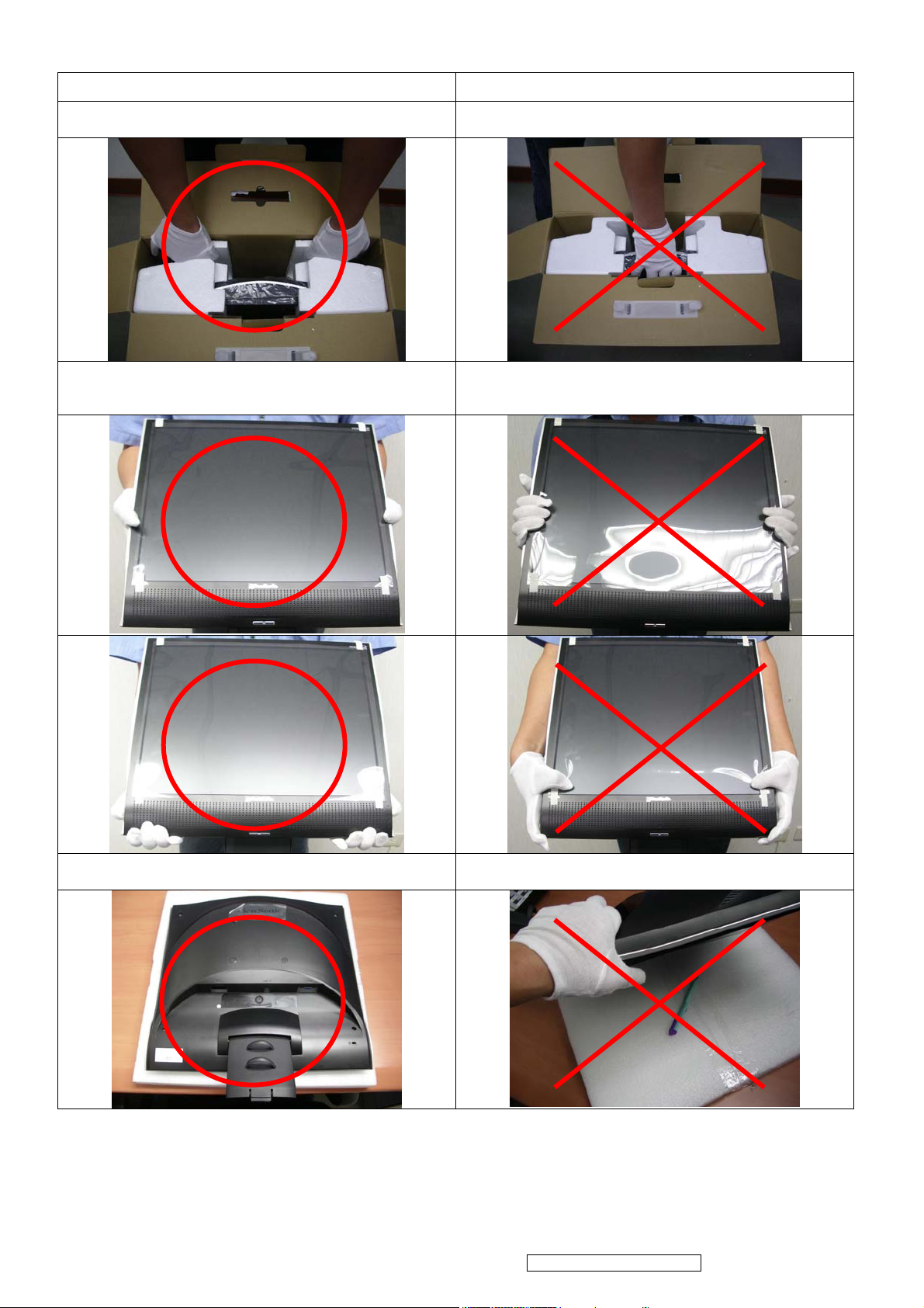
5.2 Handling and Placing Methods
Correct Methods: Incorrect Methods:
1.Take out the monitor with cushions 1.Taking out the monitor by grasping the LCD panel.
That may cause ”Mura”
2.Only touch the metal frame of the LCD panel or the
front cover of the monitor. Do not touch the surface of
the polarizer.
2.Surface of the LCD panel is pressed by fingers and
that may cause ”Mura”.
3.Place the monitor on a clean and soft foam pad. 3.Placing the monitor on foreign objects. That could
scratch the surface of the panel or cause “Mura”.
2
ViewSonic Corporation Confidential - Do Not Copy VG921m-2
Page 6
2. Specification
FEATURES VG921m
Size
Luminance (Typ)
TFTLCD PANEL
1st
HSD
HSD190SEN1-A04
Input Signal
Sync Compatibility
Compatibility
Power Voltage AC 100-240V, 50/60Hz Yes
Contrast Ratio (Typ) *1 700:1
Colors 16.2 M (6 bits + 2 bits FRC)
Response Time *1 8 ms (on/off)
Viewing Angle (H/V) 150 ° / 135 °@ CR ≥ 10
160 ° / 160 °@ CR ≥ 5
Recommend resolution 1280x1024@60Hz
Analog Yes (75ohms, 0.7/1.0 Vp-p)
Digital NO
Separate Sync Yes
Composite Sync Yes
Sync on Green Yes
PC Yes
Power Mac Yes
19 "
300 cd/㎡
On Mode(Max) ≦ 36 W Power
Consumption
Audio 1.5W / THD 0.5% (Max) Yes
Ergonomics
OSD Control [ 1 ] [ 2 ] [ ] [▼] [▲] [Mute] Yes
Dimension
Weight
Operating
Condition
Storage Condition
Off Mode (Max) ≦1 W
Tilt ( 20 ° - -5 °)
Swivel No
Pivot No
Height Adjust No
Physical (W x H x D) 425.4 mm x 457.7 mm x 205 mm
Package (W x H x D) 497 mm x 516 mm x 158 mm
Physical (Net Weight) 5.2Kg (11.5 lbs)
Package (Gross Weight) 6.8Kg (14.9 lbs)
Temperature (℉/℃) 32℉-104℉ / 0℃-40℃
Humidity (%) 20 % - 80 %
Temperature (℉/℃) -4℉-140℉ / -20℃-60℃
Humidity (%) 10% - 90 % (no condensation)
Yes
UL/CUL, FCC (ICES-003B), CB, CE, TCO'03, GS, ERGO(covers
ISO13406-2 & MPRII), IRAM, VCCI, GOST-R, HYGIENIC (20
Regulation
3
ViewSonic Corporation Confidential - Do Not Copy VG921m-2
copies), Energy Star, CCC, BSMI, PSB, C-TICK, SASO, WEEE,
RoHS, Windows Vista Basic
Page 7
Audio Interface (Speaker Specification)
Line input connection 3.5 mm stereo jack
Line input signal 1.0 Vrms
Line input impedance 10 kOhm
Maximum power output (Electric) 1.2 W / ch
Speaker 1.5W / ch (max)
Signal to Noise Ratio 50 dB
Frequency response 100 Hz – 20 kHz
Distortion < 10 % THD (@1kHZ)
Vibration
Screen image
Connector PC99 requirement Audio in Lime Green pantone # 577C
Cable type / length 3.5mm stereo cable / 1.8m length
Audio DPMS
Panel Characteristics:
1st Source Panel
There should be no audible vibration with
volume at 100% and treble / bass at default.
There should be no affect on the screen
image stability under any conditions.
Speakers should be off when the rest of the
monitor is in power saving.
Model number HSD190SEN1-A04
Type Active Matrix TFT, TN technology
Active Size 19” (376.32mm x 301.056mm)
Pixel Arrangement RGB Vertical Stripe
Pixel Pitch 0.294 mm
Glass Treatment Anti-Glare, Hard coating (3H)
# of Backlights 4 CCFL
Backlight Life 50000 Hrs (Min)
Luminance (Center) –
CT = 6500K,
Contrast/ Brightness = Max
300 cd/m2 (Typ)
240 cd/m2 (Min)
Brightness Uniformity (13 points) 75 % (Min)
Contrast Ratio 700 :1 (Typ)
450 : 1 (Min)
Color Depth 16.2 million colors (6+2 bit panel)
150 degrees (Typ) / 130 degrees (Min) @ CR>10
Horizontal Viewing Angle
160 degrees (Typ) @ CR>5
Vertical Viewing Angle
135 degrees (Typ) / 110 degrees (Min) @ CR>10
160 degrees (Typ) @ CR>5
Response Time
On-Off
10%-90% @ Ta=25°C 8ms (Typ) / 12ms (Max)
Mercury 3.0 mg per lamp
Panel Defects Please see Panel Quality Specifications.
4
ViewSonic Corporation Confidential - Do Not Copy VG921m-2
Page 8
ELECTRICAL REQUIREMENT
Horizontal / Vertical Frequency
Horizontal Frequency
Vertical Refresh Rate
Maximum Pixel Clock 135 MHz
Sync Polarity Independent of sync polarity
Timing Table
Item Timing
1 640 x 350 @ 70 Hz, 31.5 KHz
2 640 x 400 @ 60 Hz, 31.5 KHz
3 640 x 400 @ 70 Hz, 31.5 KHz
640 x 480 @ 50 Hz, 24.7 KHz
4
5 640 x 480 @ 60 Hz, 31.5 KHz
24 – 82 kHz
50 – 75 Hz
Analog
Composite
Separated
Digital - TMDS
SOG
The image quality might be
worse than 640x480@60Hz
Remark
640 x 480 @ 67 Hz, 35 KHz
6
7 640 x 480 @ 72 Hz, 37.9 KHz
8 640 x 480 @ 75 Hz, 37.5 KHz
9 720 x 400 @ 70 Hz, 31.5 KHz
10 800 x 600 @ 56 Hz, 35.1 KHz
11 800 x 600 @ 60 Hz, 37.9 KHz
12 800 x 600 @ 72 Hz, 48.1 KHz
13 800 x 600 @ 75 Hz, 46.9 KHz
14 832 x 624 @ 75 Hz, 49.7 KHz
15 1024 x 768 @ 60 Hz, 48.4 KHz
16 1024 x 768 @ 70 Hz, 56.5 KHz
17 1024 x 768 @ 75 Hz, 60 KHz
18 1152 x 864 @ 75 Hz, 67.5 KHz
19
1152 x 870 @ 75 Hz, 68.7 KHz
20 1280 x 720 @ 60 Hz, 45 KHz
DMT
DMT
DMT
DMT
DMT
DMT
MAC
DMT
DMT
DMT
DMT
For MAC
DTV
21 1280 x 1024 @ 60 Hz, 64 KHz
22 1280 x 1024 @ 75 Hz, 80 KHz
*1. Tolerance ≧ ±2KHz (if no overlapping issue)
*2. Any timing not in the list, it should display as normal or show on “OUT OF RANGE” OSD message without
blanking.
*3. The image quality of 50Hz mode might be worse than 60Hz.
5
DMT
DMT
ViewSonic Corporation Confidential - Do Not Copy VG921m-2
Page 9
3. Front Panel Function Control Description
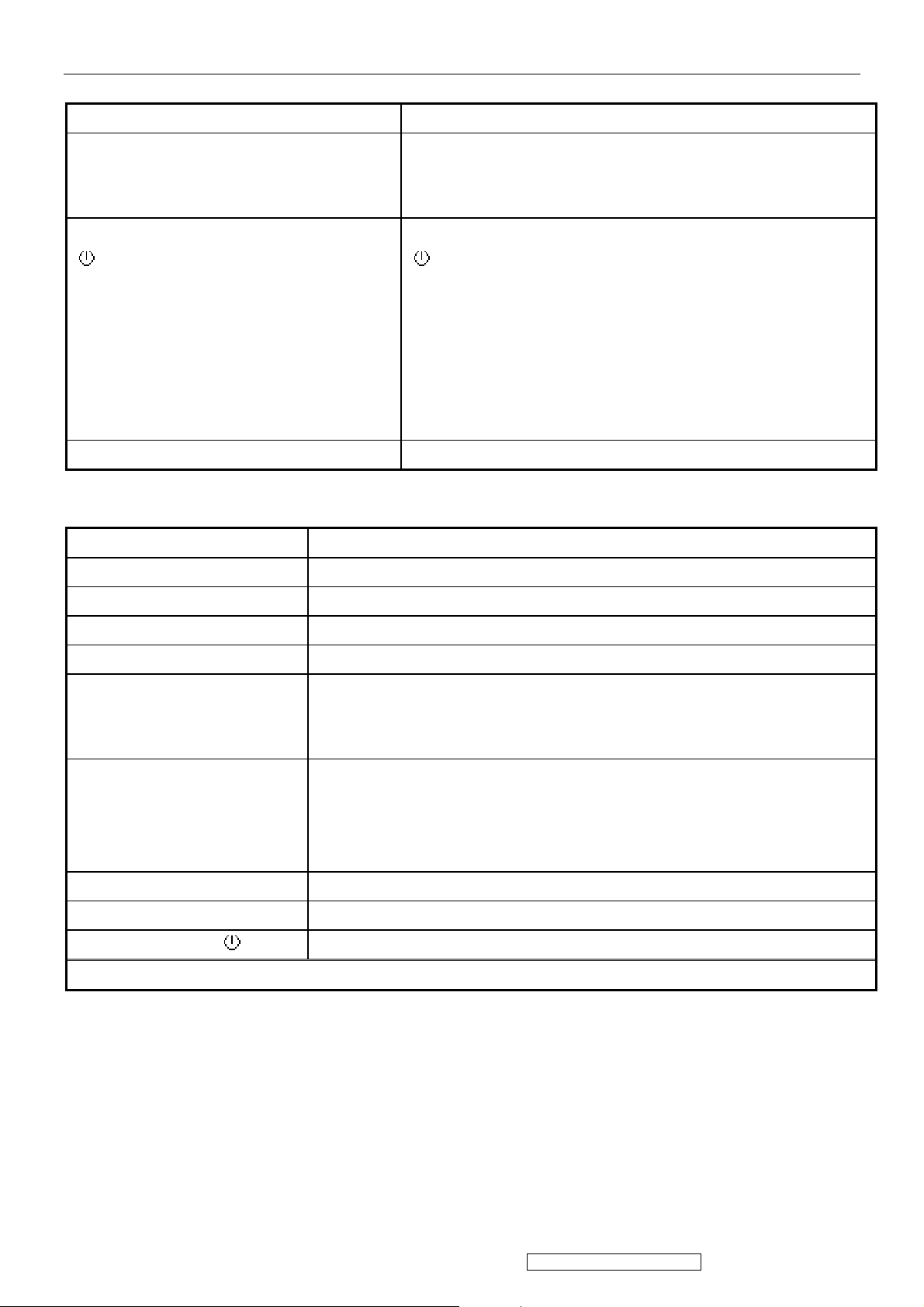
3.1 Front Panel Hardware Controls
Power Switch (Front Head) Power Control, soft Power Switch.
Power LED (Front Head) Green – ON
Orange – Power Saving Mode
Dark = Soft Power Switch OFF
Front Panel Controls (Head)
[
] [ 1 ] [ 2 ] [▲] [▼] [;X]
Reaction Time OSD must fully appear within 0.5s after pushing Button 1
3.2 Short Cuts Function from the button(s)
[1] Main Menu
[2] Auto Image Adjust
[▼] Brightness adjust
[▲] Contrast adjust
[▼]+ [▲] recall both of Contrast and Brightness to default
[;X] Mute
[
] Power
[ 1 ] BUTTON 1
[ 2 ] Button 2
[▲] UP ARROW BUTTON
[▼] DOWN ARROW BUTTON
Note: Power Button, Button 1 and Button 2 must be one-shot logic
operation. (i.e. there should be no cycling)
[1] + [2] 1. toggle 720x400@70Hz/640x400@70Hz mode when input one of the two mode
2. toggle 640x480@60Hz/640x400@60Hz mode when input one of the two mode
[1] + [▼] + [▲] White Balance.
*1. Not shown on user’s guide
*2. Recommend resolution = 640x480@60Hz)
[1] + [▼] Power Lock
[1] + [▲] OSD Lock
Signal + [1] + [ ] Factory Mode (include burning mode)
Remark : All the short cuts function are only available while OSD off
6
ViewSonic Corporation Confidential - Do Not Copy VG921m-2
Page 10
3.3 Function descriptions
Main Menu Controls
The Main Menu OSD includes most of control functions.
Please refer to APPENDIX C (Main Menu OSD Table) for the detail.
OSD Lock short cuts function for the buttons
The OSD lock will be activated by pressing the front panel control buttons "(1), & (▲)" for 10 seconds. If the user then tries to
access the OSD by pressing any of the buttons "1", "▼", "▲", "2" a message will appear on the screen for 3 seconds showing
"OSD Locked". The OSD lock will be deactivated by pressing the front panel control buttons "(1), & (▲)" again for 10
seconds.
Note 1: When the OSD is locked will lock all functions, including “Volume” and “Mute”
Note 2: Status bar indicating OSD Lock or Unlock is in progress and when complete it will indicate “OSD Locked”
Note 3: OSD Lock should not lock Power Button and Power Lock function
Power Lock short cuts function for the buttons
The power button lock will be activated by pressing the front panel control buttons "(1), & (▼)" for 10 seconds. Locking the
power button means that the user won't be able to turn off the LCD while the power button is locked. If the user presses the
power button while it is locked, a message will appear on the screen for 3 seconds showing "Power Button Locked". It also
means that with the power button locked, the LCD would automatically turn back "On" when power is restored after a power
failure. If the power button is not in the locked mode, then power should return to it's previous state when power is restored
after a power failure. The power button lock will be deactivated by pressing the front panel control buttons "(1), & (▼)" again
for 10 seconds.
Note 1: Status bar indicating Power Button lock or unlock is in progress and when complete it will indicate “Power Button
Locked”
Note 2: Power should only be lockable in the “On State”
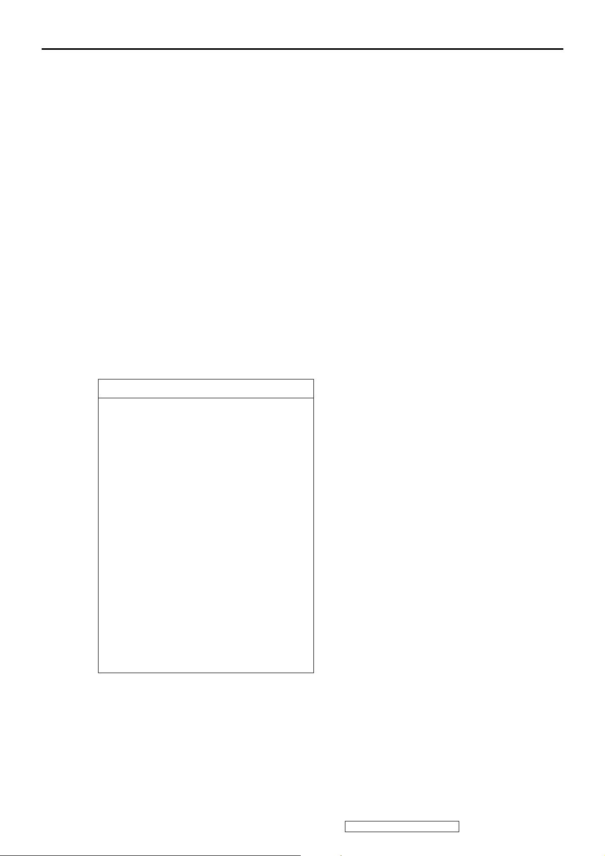
Memory Recall Actions
Memory Recall action as below
1. Recall white balance to factory setting
2. Set the factory defaults as shown in Section 4-8
3. Clean all the mode setting buffer
4. Execute Auto Image Adjust
Note: Memory Recall should have no effect for Language, Power Lock, User Color Settings or Input Priority
Input Signal Notice Actions
1. The Input Signal Notice OSD appears 3 seconds when power turns on or change input signal.
2. The Input Signal Notice OSD position is on the right-bottom side of image. And the OSD background shall be transparent.
(OSD Background = off).
Resolution Notice Ac tions
1. Resolution Notice OSD should show on screen after changing to non-native mode for 30 sec
2. For auto input select function, it shall meet the requirement in Appendix D.
3. The OSD should disappear after 10 sec or by pushing button [1] or [2]
Resolution Notice function should be disabled when push button [2] under Resolution Notice OSD
7
ViewSonic Corporation Confidential - Do Not Copy VG921m-2
Page 11
0-Touch™ Function Actions
1. Execute Auto Image Adjust when new mode detected, and save the settings to buffer for further use
2. It should be reset by Memory Recall function
(Should not reset by power off, power unplug and others)
OSD Auto Save
The OSD shall save new settings when it is turned off by the user or when it times out. There shall not be a separate save
3.4 Factory Defaults
Item Defaults Item Defaults
Contrast 70% Input Priority N/A
Brightness 100% Resolution Notice On
Color Temperature 6500K Volume 50%
Sharpness 100% Balance N/A
OSD H. Position 50% Treble N/A
OSD V. Position 50% Bass N/A
OSD Time Out 15 720x400 / 640x400 (@70Hz) 720x400
OSD Background On 640x480 / 640x400
(@60Hz)
640x480
8
ViewSonic Corporation Confidential - Do Not Copy VG921m-2
Page 12
3.5 OSD Menu Controls
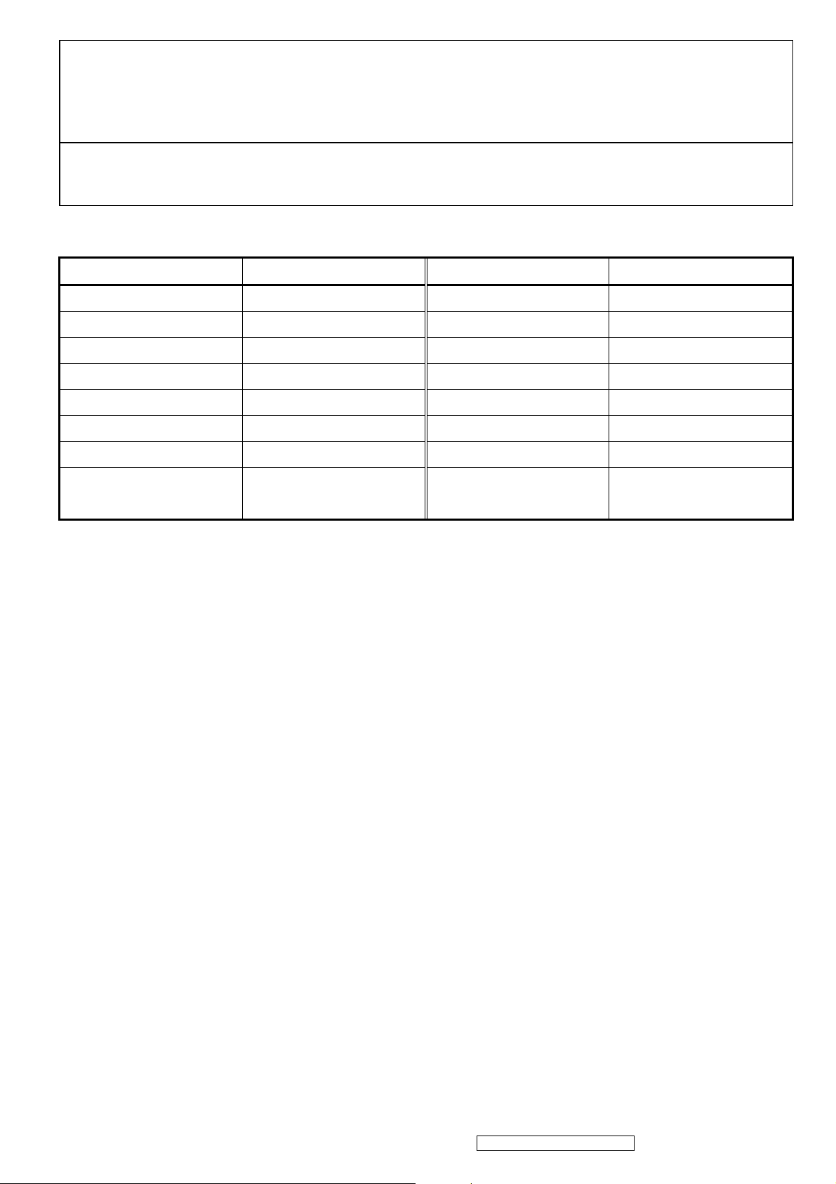
Select the menu items shown below by using the up [▲] and down [▼] buttons.
Main Menu :
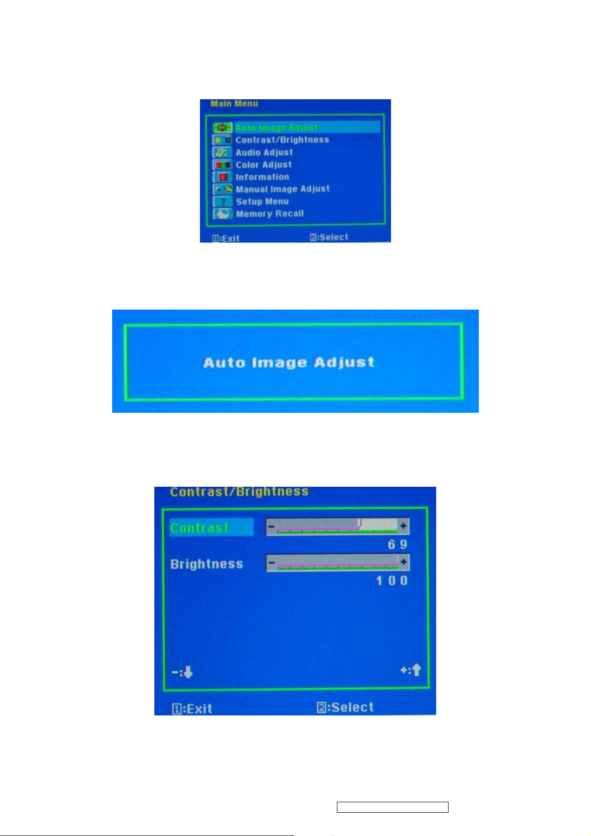
Auto Image Adjust :
To automatically adjust H./ V. Position, Phase adjust and Clock adjust.
REMARK: There may need to select “Manual Image Adjust” to optimized Performance for various VGA tolerance.
Contrast / Brightness :
To adjust the Contrast of the video and the backlight currency.
REMARK: 1. These functions setting can be recalled to default by [Up] + [Dn].
2. These functions should be disabled and setting to default in sRGB Mode.
9
ViewSonic Corporation Confidential - Do Not Copy VG921m-2
Page 13
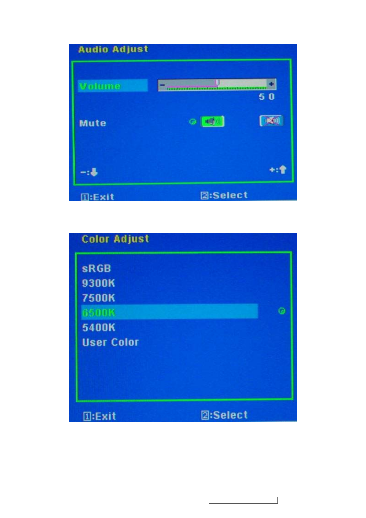
Audio Adjust :
To adjust the audio volume and mute.
Color Adjust :
To select the color temperature sRGB, 9300°K, 7500°K ,6500°K, 5400°K or user color.
10
ViewSonic Corporation Confidential - Do Not Copy VG921m-2
Page 14
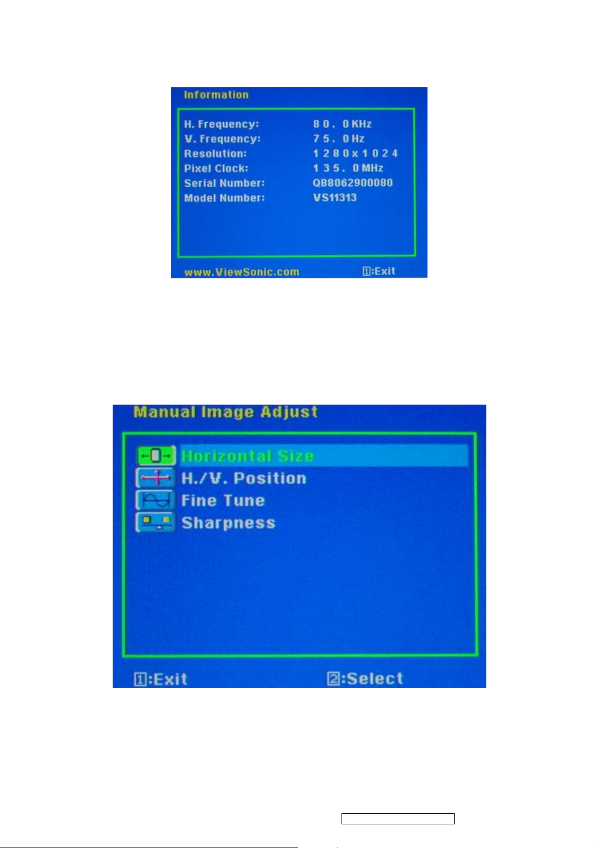
Information:
To display the data about Horizontal / Vertical frequency, Pixel clock, Resolution , Model number and Serial No. of the
monitor.
Manual Image Adjust:
Horizontal Size: To adjust the horizontal pixel clock of the video.
H./V. Position: To adjust the horizontal and vertical position of the video.
Fine Tune: To adjust the delay time of data and clock.
Sharpness: To select the picture sharpness of display.
REMARK: This function is available under Native Resolution Mode.
11
ViewSonic Corporation Confidential - Do Not Copy VG921m-2
Page 15
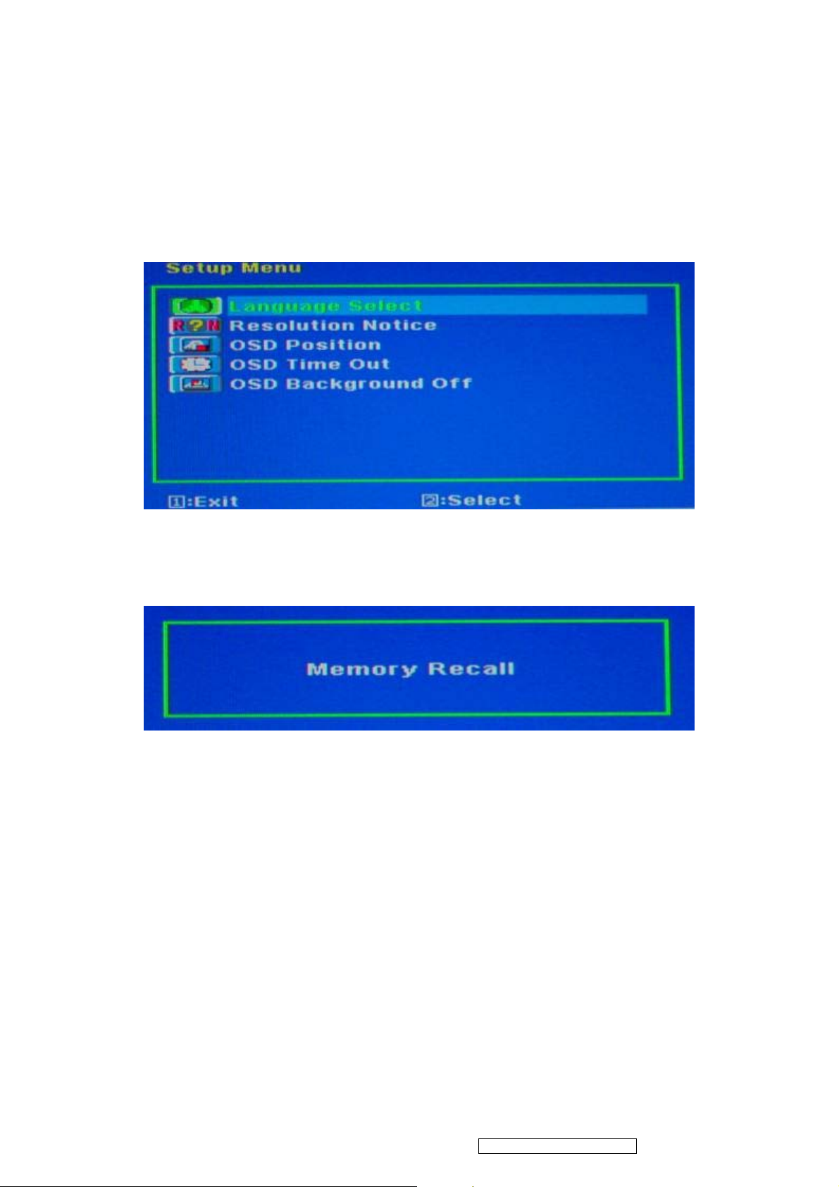
Setup Menu:
Language Select: To select one of eight languages.(English, French, German, Spanish, Italian, Finnish, Japanese,
Traditional Chinese, and Simplified Chinese)
Resolution Notice: Enable (on) : OSD will notify the best picture quality resolution change the resolution to 1280 x
1024.
OSD Position: To set OSD position.
OSD Timeout: To set the displaying time of OSD ( 5” / 15” / 30” / 60” ).
OSD Background: To select video background brightness.
Memory Recall:
Restore default settings of Clock, H./V. Position, Phase, Contrast, Brightness, Color temperature, OSD position, OSD
timeout and Sharpness, Volume.
12
ViewSonic Corporation Confidential - Do Not Copy VG921m-2
Page 16

4. Circuit Description
1. Power supply (DC/DC Converter)
This brick convert is the 110-220AC input voltage to 12V AND 5V output for inverter,
audio, panel and system controller use.
It consists of a PWM IC (CM0565R, U101)
2. Scaling controller
The ADC is to convert RGB analog signal to digital signal that scaling chip can
acknowledge.
The HSYNC input receives a logic signal and provides the frequency reference for
pixel clock generation.
The scaling IC is to converts the input signal ranging from VGA to SXGA.
GENERAL DESCRIPTION
The TSUM57AK is a high performance, and fully integrated graphics processing IC solution
for LCD monitors with resolutions up to SXGA. It is configured with an integrated triple-ADC/PLL,
a high quality scaling engine, an on-screen display controller, a built-in output clock generator,
and LVDS display interface. To further reduce system costs, the TSUM57AK also integrates
intelligent power management .
13
ViewSonic Corporation Confidential - Do Not Copy VG921m-2
Page 17
5. Adjustment Procedure
1. Function Test
1.1 Product
- 19” LCD Monitor
1.2 Test Equipment
- Color Video Signal & Pattern (or PC with SXGA resolution and a sound card)
1.3 Test Condition
Before function test and alignment, each LCD Monitor should be run-in and warmed
up for at least 30 minutes with the following conditions:
(a) In room temperature,
(b) With full-white screen, RGB, and Black
(c) With cycled display modes,
640*480 (H=37.5kHz, V=75Hz)
800*600 (H=46.9kHz, V=75Hz)
1024*768 (H=60kHz, V=75Hz)
1280*1024 (H=80kHz, V=75Hz)
1.4 Test Display Modes & Pattern
1.4.1 Compatible Modes
Analog
1. 640 x 480 @ 60Hz, 31.5kHz
2. 640 x 480 @ 67Hz, 35.0kHz
3. 640 x 480 @ 72Hz, 37.9kHz
4. 640 x 480 @ 75Hz, 37.5kHz
5. 720 x 400 @ 70Hz, 31.5kHz
6. 800 x 600 @ 56Hz, 35.1kHz
7. 800 x 600 @ 60Hz, 37.9kHz
8. 800 x 600 @ 72Hz, 48.1kHz
9. 800 x 600 @ 75Hz, 46.9kHz
10. 832 x 624 @ 75Hz, 49.7kHz
11. 1024 x 768 @ 60Hz, 48.4kHz
12. 1024 x 768 @ 70Hz, 56.5kHz
13. 1024 x 768 @ 75Hz, 60.0kHz
14. 1280 x 1024 @ 60Hz, 64.0kHz
15. 1280 x 1024 @ 75Hz, 80.0kHz
14
ViewSonic Corporation Confidential - Do Not Copy VG921m-2
Page 18
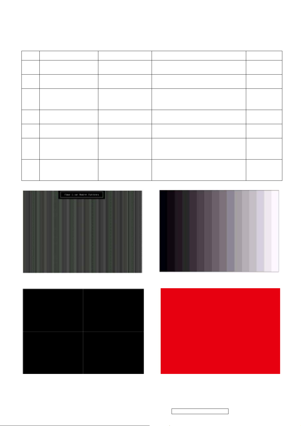
1.4.2 Function Test Display Pattern
Item Test Content Pattern Specification Remark
1 Frequency &
Tracking
2 Contrast/Brightness 16 Gray Scale 16 gray levels should be
3 Boundary Horizontal &
4 RGB Color
Performance
5 Screen Uniformity
& Flicker
6 Dead Pixel/Line White Screen &
7 White Balance White & Black
Fine Line Moire Eliminate visual wavy
noise.
distinguishable.
Horizontal and Vertical position
Vertical
Thickness
RGB Color
Intensities
Full White Should be compliant with the
Dark Screen
Pattern
of video should be adjustable to
be within the screen frame.
Contrast of each R, G, B, color
should be normal.
spec.
The numbers of dead pixels
should be compliant with the
spec.
The screen must have the pure
white and black pattern, no other
color.
Figure 1
Figure 2
Figure 3
Figure 4, 5,
6
Figure 7
Figure 7, 8
Figure 9
Fine Line Morie Pattern (Figure1) Gray Scale Pattern (Figure2)
Horizontal & Vertical Thickness Pattern
(Figure 3)
15
ViewSonic Corporation Confidential - Do Not Copy VG921m-2
R. Color Pattern (Figure 4)
Page 19
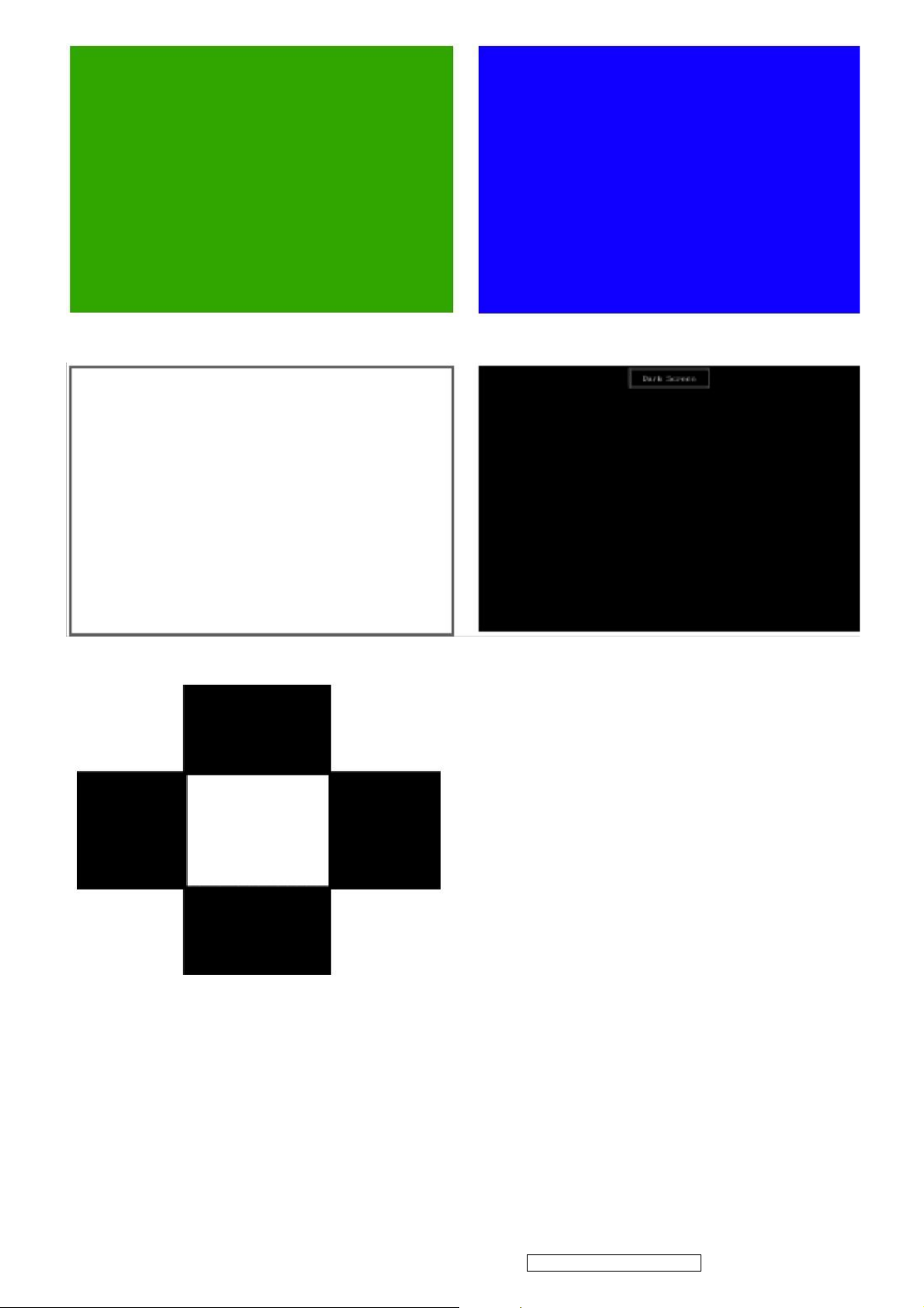
G. Color Pattern (Figure5) B. Color Pattern (Figure 6)
Full White Patter (Figure 7) Dark Screen Pattern (Figure 8)
Black-White Pattern (Figure 9)
16
ViewSonic Corporation Confidential - Do Not Copy VG921m-2
Page 20

1.5 Function Test and Alignment Procedure
1.5.1 Memory Recall
You should do “Memory Recall” first. This action will allow you to erase all
end-user’s settings and restore the factory defaults.
1.5.2 Auto Image Adjust
Please select and enter “Auto Image Adjust” function on Main Menu to see if it is
workable.
The “Auto Image Adjust” function is aimed to offer a better screen quality by
built-in ASIC. For optimum screen quality, the user has to adjust each function
manually.
1.5.3 Firmware
Test Pattern: Burn In Mode ( Refer to Chapter 3-2. Short Cuts Function from the
button(s) )
- Make sure the F/W is the latest version.
1.5.4 DDC
Test Pattern: EDID program
- Make sure it can pass test program.
1.5.5 Fine Tune and Sharpness
Test Signal: 1280x1024@60Hz
Test Pattern: Line Moire Pattern
- Check and see if the image has noise and focus performs well. Eliminate visual line
bar.
- If not, readjust by the following steps:
(a) Select and enter “Fine Tune” function on “Manual Image Adjust” to adjust the
image
to eliminate visual wavy noise.
(b) Then, select and enter “Sharpness” function to adjust the clarity and focus of the
screen image.
1.5.6 Boundary
Test Signal: 1280x1024@60Hz
Test Pattern: Horizontal & Vertical Line Thickness Pattern
- Check and see if the image boundary is within the screen frame.
- If not, readjust by the following steps:
(a) Select and enter “Manual Image Adjust” function on OSD Main Menu.
(b) Then, select and enter “Horizontal Size” or “Horizontal/Vertical Position”
function to adjust the video boundary to be full scanned and within screen frame.
17
ViewSonic Corporation Confidential - Do Not Copy VG921m-2
Page 21

1.5.7 White Balance
Test Signal: 1280x1024@60Hz
Test Pattern: White and Black Pattern
1.5.8 R, G, B, Colors Contrast
Test Signal: 1280x1024@60Hz
Test Pattern: R, G, B, Color Intensities Pattern and 16 Gray Scale Pattern
- Check and see if each color is normal and distinguishable.
- If not, please return the unit to repair area.
1.5.9 Screen Uniformity and Flicker
Test Signal: 1280x1024@60Hz
Test Pattern: Full White Pattern
- Check and see if it is in normal condition.
1.5.10 Dead Pixel and Line
Test Signal: 1280x1024@60Hz
Test Pattern: Dark and White Screen Pattern
- Check and see if there are dead pixels on LCD panel with shadow gauge and filter
film.
- The total numbers and distance of dead pixels should be compliant with the spec.
1.5.11 Mura
1.5.12 Audio
resonance.
Test Pattern: White, RGB, Black, & Grey
Test Tool: 8% ND Filter
- Check if the Mura can pass 8% ND Filter.
Test Signal: Voice signal (optional, depend on model)
Test Pattern: liberty
- Make sure there is audio output.
- Make sure that audio function (volume≦80%) is working without noise and
- Make sure that the sound of right and left speakers are in balance.
1.5.13 Check for Secondary Display Modes
Test Signal : Analog
640*350@70Hz 640*480@60HZ / 75HZ 720*400@70Hz
800*600@60HZ / 75HZ 832*624@75Hz 1024*768@60HZ / 75HZ
1280x1024@75Hz
- Normally when the primary mode 1280x1024@60Hz is well adjusted and compliant
18
ViewSonic Corporation Confidential - Do Not Copy VG921m-2
Page 22

with the specification, the secondary display modes will be great possible to be
compliant with the spec. But we still have to check with the general test pattern to
make sure every secondary is compliant with the specification.
1.5.14 Memory Recall
After final QC step, we have to erase all saved changes again and restore the
factory defaults. You should do “Memory Recall” again.
1.5.15 Power Off Monitor
Turn off the monitor by pressing “Power” button.
2. Firmware Upgrade Procedure
When you receive the returned monitor, please check whether the firmware version is the
latest.
If not, please do the following procedures to upgrade it to the latest version.
2.1 Equipment Needed
- VG921m Monitor
- Fixture for Firmware Upgrade
- VGA Cable
- PC (Personal Computer)
- ISP Tool
- Firmware Upgrade Program
- One additional monitor for checking the program execution
ISP tool instruction
15 pin D-Sub LPT cable
19
ViewSonic Corporation Confidential - Do Not Copy VG921m-2
Page 23

ISP tool Use 12V adapter
ISP connect method
ISP Download program procedure
Hardware Connect status:
Version update
1. Check : Monitor model
2. Check : Firmware version
20
ViewSonic Corporation Confidential - Do Not Copy VG921m-2
Page 24

Factory Mode :
a. Hold on [2] + [ ] with signal (hold for 3 seconds) into the factory mode.
b. Press [ ] key exit factory mode.
3. Update final firmware version
Example : ( VG921m follows the same setting procedure )
1. Check : Monitor model : HC154
2. Check : Firmware version : HC154_AL_150MX17A01R30.2 (ps)
3. Update final firmware version : HC154_AL_150MX17A01R30.3
(ps) HC154_AL_150MX17A01R30.2
AL : Analog / LVDS
DL : Analog + Digital / LVDS
AR : Analog /RSDS
DR : Analog + Digital / RSDS
Panel type : 150MX17A01
Firmware version : R30.2
Change Panel (Version update)
1. Check : Monitor model
2. Check : Firmware version
21
ViewSonic Corporation Confidential - Do Not Copy VG921m-2
Page 25

Factory Mode :
a. Hold on [2] + [ ] with signal (hold for 3 seconds) into the factory mode.
b. Press [ ] key exit factory mode.
3. Check : Panel type.
4. Change Panel.
5. Update final firmware version.
6. Update EDID code.
Example : ( VG921m follows the same setting procedure )
1. Check : Monitor model : HC154
2. Check : Firmware version : HC154_AL_150MX17A00R30.2 (ps.1)
3. Check : Panel type : HSD150MX17A00.
4. Change Panel. (ps.2)
(ps.1) HC154_AL_150MX17A00R30.2
AL : Analog / LVDS
DL : Analog + Digital / LVDS
AR : Analog /RSDS
DR : Analog + Digital / RSDS
Panel type : 150MX17A01
Firmware version : R30.2
(ps.2) If change panel : (Form HSD150MX17A00 change to HSD150MX17A01)
Panel type : 150MX17A00 => 150MX17A01
Firmware change : HC154_AL_150MX17A00R30.2 =>
22
ViewSonic Corporation Confidential - Do Not Copy VG921m-2
Page 26

HC154_AL_150MX17A01R30.2
5. Update final firmware version : HC154_AL_150MX17A01R30.3
6. Update EDID code : HC154_150MX17A01_EDID_A.txt
Change Scaler Board (Version update)
1. Check : Monitor model
2. Check : Firmware version
Factory Mode :
a. Hold on [2] + [ ] with signal (hold for 3 seconds) into the factory mode.
b. Press [ ] key exit factory mode.
3. Change scaler board.
4. Update final firmware version.
5. Update EDID code.
Example : ( VG921m follows the same setting procedure )
1. Check : Monitor model : HC154
2. Check : Firmware version : HC154_AL_150MX17A01R30.2 (ps)
(ps) HC154_AL_150MX17A01R30.2
AL : Analog / LVDS
DL : Analog + Digital / LVDS
AR : Analog /RSDS
DR : Analog + Digital / RSDS
Panel type : 150MX17A01
Firmware version : R30.2
3. Change scaler board.
4. Update final firmware version : HC154_AL_150MX17A01R30.3
5. Update EDID code : HC154_150MX17A01_EDID_A.txt
Mstar scaler ISP function
1. Enforce Mstar ISP_Tool program.
23
ViewSonic Corporation Confidential - Do Not Copy VG921m-2
Page 27

2. After Enforcing Mstar ISP_Tool Program, open Utility Window.
3. Enforce Mstar ISP Utility Window's Connect function, and Device Type's Dialog
window will be opened ,then press "Sure " on Dialog window.
4. Enforce Mstar ISP Utility window’s Read function.
5. Choose the path and the file of Binary code.
24
ViewSonic Corporation Confidential - Do Not Copy VG921m-2
Page 28

6. Choose the path and file of Binary code ,and Program Bin Ready Dialog window will
be opened, then press "Sure" on Dialog window.
7. Enforce Mstar ISP "Auto" function of Utility window.
8. Enforce Mstar ISP Utility window "Run" and write in the data .
25
ViewSonic Corporation Confidential - Do Not Copy VG921m-2
Page 29

9. After writing in the dat a , Enforce Dis Connect function of Mst ar ISP Utility window and
the burn in procedure will be completed.
26
ViewSonic Corporation Confidential - Do Not Copy VG921m-2
Page 30

DDC Key In Procedure
Note:
1. Every time after replacing the main board, you have to do the DDC key in.
2. If you find the DDC does not conform to the monitor, you have to do the DDC key in.
Equipment Needed
- VG921m Series Monitor
- DDC Card
- PC
- RS232 cable
- VGA Cable or DVI Cable
DDC Card (D8330)
RS-232 Cable VGA Cable
Step 1 : Select VG921m in Working Model column to show EDID data on left.
Example : VX1935wm ( VG921m follows the same setting procedure )
27
ViewSonic Corporation Confidential - Do Not Copy VG921m-2
Page 31

Step 2 : Modify the column of Week of Manufacture and Year of Manufacture and ID serial
Number then press “2B” button for changing serial number data.
Example : VX1935wm ( VG921m follows the same setting procedure )
Step 3 : You will see the result as follows.
28
ViewSonic Corporation Confidential - Do Not Copy VG921m-2
Page 32

Packing For Shipping And Disassembly Procedure
Packing For Shipping
1. Packing Procedure
1.1 Put the monitor in the PE bag and seal the bag with tape. (Figure 1 ~ 2)
1.2 Put the cushions on the monitor. (Figure 3) 1.3 Put the Cables in the PE bag. (Figure 4)
(Figure 1) (Figure 2)
D-Sub cable Power cord Audio cable
(Figure 3) (Figure 4)
1.4 Place the monitor into the carton and then put all the accessories into the carton. At last,
close the carton and seal it with tape. (Figure 5 ~ 6)
Base short side turn upward
User’s manual / Warranty card/
CD package
Power Cord /
Panel side forward
D-Sub Cable
Audio Cable
29
ViewSonic Corporation Confidential - Do Not Copy VG921m-2
(Figure 5) (Figure 6)
Page 33

2. Disassembly Procedure
1. Remove the base cover. 2. Remove the hinge cover.
3. Unfasten 4 pcs of screws to remove
base.
4. Unfasten 4 pcs of screws with back
cover.
5. Separate the Cover from the bottom of the Housing by using a Flat tool to
remove back cover.
30
ViewSonic Corporation Confidential - Do Not Copy VG921m-2
Page 34

6. Disconnect the cables of Power-Key
board and remove it.
8. Unfasten 2 pcs of screws to remove
left speaker.
7. Unfasten 2 pcs of screws to remove
right speaker.
9. Tear off the tape.
10. Unfasten 2 pcs of screws to remove
key board.
31
ViewSonic Corporation Confidential - Do Not Copy VG921m-2
11. Pull and open the fixed support to
remove Front Bezel.
Page 35

12. Disconnect the cables of P/I/A
board.
14. Unfasten 5 pcs of screws with
Shielding.
13. Tear off the tape with the Shielding.
15. Disconnect the cables of P/I board.
16. Disconnect the cables of D-Sub. 17. Unfasten 8 pcs of screws to remove
P/I/A board.
32
ViewSonic Corporation Confidential - Do Not Copy VG921m-2
Page 36

18. Disconnect the cables of P/I/A
board.
20. Unfasten 5 pcs of screws to remove
D-Sub board.
19. Set the short pin before changing
new P/I/A board.
21. Disconnect the cables of D-Sub
board.
33
ViewSonic Corporation Confidential - Do Not Copy VG921m-2
Page 37

6. Troubleshooting Flow Chart
Q1
NO POWER
Please check if power cable is
connected properly
YES
NO
Q2
NO DISPLAY
Please check if signal cable is
connected properly
YES
NO
Change P/I/A board (ps)
Please reconnect power
cable
Change Panel
Please reconnect signal
cable
Q3
Display panel have horizontal
line or vertical line
Q4
The backlight is OFF
Please change panel
1
Please check inverter
wire if properly connected
Please change panel or
2
P/I/A board (ps)
34
ViewSonic Corporation Confidential - Do Not Copy VG921m-2
Page 38

Q5
Display panel have block bar
Q6
Display panel with missing
color
Please change
1
Please check signal cable if
connected properly and
check all pins are good
without bent
2
3
Q7
Audio output error
(ps) : P/I/A board Power/Inverter/Audio board
Please check if panel wire is
loose connection or not
Please change panel
Please change P/I/A
board (ps)
35
ViewSonic Corporation Confidential - Do Not Copy VG921m-2
Page 39

7. Block Diagram
AC
INPUT
100V~240V
AUDIO
U501
TDA7496
SPEAKER
AUDIO
INPUT
CN501
SW Power
12V
5V
INVERTER
MP 1038EY
BL_EN
BL-BRIGHT
OSC 12M
Y1
+5V
PANEL
DISPLAY
SCALAR
U401
TSUM57AK
DC-DC
U3
AIC1084-33PM
3.3V
DC-DC
U301
G1117-33
1.8V
EEPROM
U1
AT24C16N-10SC-2.
7
Flash
U402
H、SYNC
V、SYNC
H、V SYNC
VGA D-SUB
SCL、SDA
VGA 5V
CONN CN4
R、G、
BINPUT
DDC
U6
AT24C02
SST25VH010
36
ViewSonic Corporation Confidential - Do Not Copy VG921m-2
Page 40

8. Schematic Diagrams
VDD12
R204
C218
100KΩ 1/16W
R205
11.5k 1%
GND
0.1u/NC
NC
C217
18pF
VCC
R527
33k/NC
C225
GND
GND
VDD+5
R216
0Ω 1/16W
SD
R206
75KΩ 1/16W
GND
C219
0.0022uF
GND
SD
U202
1
OUT
2
S-80924LMC-G6U-T2G/NC
CD
VDD
GND3NC
C200
10uF/16V
1
2
3
R526
0Ω 1/16W
5
4
GND
U200
COMP
FB
FREQ
SHDN
GND4LX
AAT1102
R215
0/NC
GND
C203
0.1uF/16V
SS
IN
C226
220p/NC
8
7
6
5
XAO
R201
0Ω 1/16W
C220
0.068uF/16V
GND
L200
LK.CD032.A01
D105
SSM5818SPT
1 2
C207
C221
3
0.47uF/25V
1uF
GND
C211
0.22uF/25V
1
2
GND
C227
10uF/16V
D201
BAT54SPT
1
C208
1uF
GND
D215
BAT54SPT
3
R207
1KΩ 1/16W
C210
0.22uF/25V
2
1
C212
0.22uF/25V
VDD12
56KΩ 1/16W
Q209
MMBT3906
3 2
1
12
1 2
GND
VDD12
D204
BAT54SPT
3
C223
0.47uF/25V
R208
0.1uF/16V
D214
6.2V
D208
CHPT521S-30
100uF/16V
2
GND
C222
C202
10u/NC
C228
D207
CHPT521S-30
1
1 2
GND
+
Q210
C205
0.1uF/16V
MMBT3906
1
3
Q211
MMBT3904
2
R209
56KΩ 1/16W
GND
0.1uF/16V
C204
32
10KΩ 1/16W
R212
24KΩ 1/16W
R202
0Ω 1/16W
R210
GND
C213
10uF/16V
GND
VDD12
VGL
Q212
MMBT3904
3
C209
1uF
1
Q213
3
MMBT3904
2
D23
5.6V
1 2
GND
VGL: -6V
R200
0Ω 1/16W
2
R211
10KΩ 1/16W
1
VDDA:+12V
VDD+12
TP1
GND
R214
110k 1%
R213
39.2k 1%
C224
2.2u
R203
0Ω 1/16W
VGH: 23.5V
C206
0.1uF
VGH
37
ViewSonic Corporation Confidential - Do Not Copy VG921m-2
ViewSonic Corporation
Model
Title
Date Rev:
Page 41

CN5
C411
TP148
0.1uF/16V
R400
0Ω 1/16W
C140
NC
C415
TP149
XAO
NC
VCC VGLVGH
TP145
TP146
C416
C413
10u/NC
VCOM
VCOM
TP2
VCOM: 4~6V
0.1uF/16V
C412
2.2u/NC
TP150
R528
10KΩ 1/16W
C403
10uF/16V
VCOM
C418
0.1uF/16V
TP151
TP152
TP153
TP154
TP155
TP156
TP157
TP158
TP159
TP160
TP161
TP162
TP163
TP164
10uF/16V
GNDGNDGNDGND
C404
GND
VGMA0
VGMA1
VGMA2
VGMA3
VGMA4
VGMA5
VGMA6
VGMA7
VGMA8
VGMA9
VGMA10
VGMA11
VGMA12
VGMA13
1
GND
2
GND
3
GND
4
VDD
5
VDD
6
NC
7
STV
8
STV2
9
CPV
10
OE
11
NC
12
VGH
13
NC
14
VGL
15
NC
16
VGC
17
XAO
18
VCOM
19
VCOM
20
GND
21
GND
22
GND
23
GND
24
GND
25
GND
26
GND
AF724L-N2GIZ
VGMA[0..13]
VDD+12
C414
0.1uF/16V
GND
VR1
TMC3K-B10K-TR
20KΩ 1/16W
R406
13
GND
VDD+12
R405
30.1k
GND
C408
NC
STV1
CPV
OE
TP147
U400
20
V0
V1
V5
V8
V12
V13
2
C406
19
18
17
16
15
14
13
12
11
VDD
IN1
IN2
IN3
IN4
IN5
IN6
NC
INCOM
GND
BUF07703
OUT1
OUT2
OUT3
OUT4
OUT5
OUT6
OUTCOM
0.1uF/16V
GND
VDD
NC
GND
1
2
3
4
5
6
7
8
9
10
GNDGND
VGMA0
VGMA1
VGMA5
VGMA8
VGMA12
VGMA13
R404
10KΩ 1/16W
C400
+
47uF/16V
C405
0.1uF/16V
GND
VDD+12
R402
0
R401
NC
C407
10u
1206
C420
0.1u
GND
C419
NC
C421
0.1u
R422
11 1%
R413
NC
C422
0.1u
V0
R439
14.3 1%
C423
0.1u
R415
NC
R441
93.1 1%
R417
NC
V1
VGMA2
C424
0.1u
R443
27.4 1%
VGMA3
C425
0.1u
R445
21 1%
R421
NC
V5 V8
VGMA4
C426
0.1u
R447
39.2 1%
C427
0.1u
R419
46.4 1%
VGMA6
R418
NC
C428
0.1u
R403
6.2 1%
VGMA7
C429
0.1u
R420
39 1%
R416
NC
C430
0.1u
R448
39 1%
VGMA9
C431
0.1u
R414
NC
R446
21 1%
VGMA10
C432
0.1u
R444
27.4 1%
VGMA11
C433
0.1u
V12VDD+12
R442
91 1%
C434
0.1u
R440
15 1%
V13
C435
0.1u
R423
6.2 1%
GND
ViewSonic Corporation
Model
Title
Date Rev:
38
ViewSonic Corporation Confidential - Do Not Copy VG921m-2
Page 42

TP52
TP53
TP54
TP55
TP56
TP57
TP58TP51
TP60
TP61 TP67
TP63
TP65
TP64TP59
TP66
TP70
TP69
TP68TP62
B_D[0..19]
TP172
LPC
VCOM
STH_B
INV
POL
LP
MODE
TP133
C558
0.1u/NC
B_D1
R164
B_D2
100Ω 1/16W
R163
B_D0
100Ω 1/16W
C554
0.1uF/16V
TP121
TP125
TP129
GND
5S1
B_D1
B_D3
B_D4 B_D4
B_D5
B_D18
B_D19
VGMA0
VGMA1
VGMA2
VGMA3
VGMA4
VGMA5
VGMA6
VGMA7
VGMA8
VGMA9
VGMA10
VGMA11
VGMA12
B_D6
B_D7
B_D8
B_D9
B_D10
B_D11
B_D12
B_D13
B_D14
B_D15
B_D16
B_D17
5S480
VCOM
TP137
TP141
X5
1
TP2
2
TP2
3
COM2
4
COM2
5
COM2
6
NC
7
S1
8
STHR
9
D00N
10
D00P
11
VSS1
12
D01N
13
D01P
14
VSS1
15
D02N
16
DO2P
17
VSS1
18
INV
19
POL
20
STB
21
VSS1
22
CLKN
23
CLKP
24
Osel
25
VSS1
26
MODE
27
V0
28
V1
29
V2
30
V3
31
V4
32
V5
33
V6
34
VSS2
35
VSS2
36
NC
37
VDD2
38
VDD2
39
V7
40
V8
41
V9
42
V10
43
V11
44
V12
45
V13
46
R/L
47
LPC
48
VDD1
49
VDD1
50
NC
51
VSS1
52
D10N
53
D10P
54
VSS1
55
D11N
56
D11P
57
VSS1
58
D12N
59
D12P
60
VSS1
61
D20N
62
D20P
63
VSS1
64
D21N
65
D21P
66
VSS1
67
D22N
68
D22P
69
STHL
70
S480
71
NC
72
COM1
73
COM1
74
COM1
75
TP1
76
TP1
TP134
X_IC
GND
GND GND GNDGND
B_D3
R165
B_D4
100Ω 1/16W
B_D5
R166
B_D6
100Ω 1/16W
B_D7
R167
B_D8
100Ω 1/16W
B_D9
R168
B_D10
100Ω 1/16W
B_D11
R169
B_D12
100Ω 1/16W
C555
0.1uF/16V
TP122
GND
TP126
TP130
6S1
STH5-6
B_D0B_D0
B_D1
B_D2
B_D3
B_D4
B_D5
INV
POL
LP
B_D18
B_D19
MODE
VGMA0
VGMA1
VGMA2
VGMA3
VGMA4
VGMA5
VGMA6
VDDA2VDDA2
VGMA7
VGMA8
VGMA9
VGMA10
VGMA11
VGMA12
VGMA13VGMA13
LPC
VDDB2 VDDB2
B_D6
B_D8
B_D9
B_D10
B_D11
B_D12
B_D13
B_D14
B_D16
B_D17
6S480
VCOM
TP138
C559
0.1u/NC
TP142
X6
1
TP2
2
TP2
3
COM2
4
COM2
5
COM2
6
NC
7
S1
8
STHR
9
D00N
10
D00P
11
VSS1
12
D01N
13
D01P
14
VSS1
15
D02N
16
DO2P
17
VSS1
18
INV
19
POL
20
STB
21
VSS1
22
CLKN
23
CLKP
24
Osel
25
VSS1
26
MODE
27
V0
28
V1
29
V2
30
V3
31
V4
32
V5
33
V6
34
VSS2
35
VSS2
36
NC
37
VDD2
38
VDD2
39
V7
40
V8
41
V9
42
V10
43
V11
44
V12
45
V13
46
R/L
47
LPC
48
VDD1
49
VDD1
50
NC
51
VSS1
52
D10N
53
D10P
54
VSS1
55
D11N
56
D11P
57
VSS1
58
D12N
59
D12P
60
VSS1
61
D20N
62
D20P
63
VSS1
64
D21N
65
D21P
66
VSS1
67
D22N
68
D22P
69
STHL
70
S480
71
NC
72
COM1
73
COM1
74
COM1
75
TP1
76
TP1
X_IC
GND
B_D13
VCOM
R170
B_D14
100Ω 1/16W
B_D15
R171
B_D16
100Ω 1/16W
B_D17
R172
B_D18
100Ω 1/16W
B_D19
C556
0.1uF/16V
TP123
TP127
GND
TP131
INV
POL
LP
VDDB2VDDB2
STH7-8STH6-7STH5-6
VCOM
VDDA2
7S1
B_D0
B_D1
B_D2B_D2
B_D3
B_D5
B_D18
B_D19
VGMA0
VGMA1
VGMA2
VGMA3
VGMA4
VGMA5
VGMA6
VGMA7
VGMA8
VGMA9
VGMA10
VGMA11
VGMA12
VGMA13
LPC
B_D6
B_D7
B_D8
B_D9
B_D10
B_D11
B_D12
B_D13
B_D14
B_D15B_D15
B_D16
B_D17
7S480
TP139
TP143
STH6-7 STH7-8
TP135
C560
0.1u/NC
X7
1
TP2
2
TP2
3
COM2
4
COM2
5
COM2
6
NC
7
S1
8
STHR
9
D00N
10
D00P
11
VSS1
12
D01N
13
D01P
14
VSS1
15
D02N
16
DO2P
17
VSS1
18
INV
19
POL
20
STB
21
VSS1
22
CLKN
23
CLKP
24
Osel
25
VSS1
26
MODE
27
V0
28
V1
29
V2
30
V3
31
V4
32
V5
33
V6
34
VSS2
35
VSS2
36
NC
37
VDD2
38
VDD2
39
V7
40
V8
41
V9
42
V10
43
V11
44
V12
45
V13
46
R/L
47
LPC
48
VDD1
49
VDD1
50
NC
51
VSS1
52
D10N
53
D10P
54
VSS1
55
D11N
56
D11P
57
VSS1
58
D12N
59
D12P
60
VSS1
61
D20N
62
D20P
63
VSS1
64
D21N
65
D21P
66
VSS1
67
D22N
68
D22P
69
STHL
70
S480
71
NC
72
COM1
73
COM1
74
COM1
75
TP1
76
TP1
X_IC
GND
TP136
VCOM
C561
0.1u/NC
INV
POL
LP
MODEMODE
LPC
VDDA2
VCOMVCOM
GND
GND
C557
0.1uF/16V
TP124
TP128
TP132
B_D0
B_D1
B_D2
B_D3
B_D4
B_D5
B_D18
B_D19
VGMA0
VGMA1
VGMA2
VGMA3
VGMA4
VGMA5
VGMA6
VGMA7
VGMA8
VGMA9
VGMA10
VGMA11
VGMA12
VGMA13
B_D6
B_D7B_D7
B_D8
B_D9
B_D10
B_D11
B_D12
B_D13
B_D14
B_D15
B_D16
B_D17
8S1
8S480
TP140
TP144
X8
1
TP2
2
TP2
3
COM2
4
COM2
5
COM2
6
NC
7
S1
8
STHR
9
D00N
10
D00P
11
VSS1
12
D01N
13
D01P
14
VSS1
15
D02N
16
DO2P
17
VSS1
18
INV
19
POL
20
STB
21
VSS1
22
CLKN
23
CLKP
24
Osel
25
VSS1
26
MODE
27
V0
28
V1
29
V2
30
V3
31
V4
32
V5
33
V6
34
VSS2
35
VSS2
36
NC
37
VDD2
38
VDD2
39
V7
40
V8
41
V9
42
V10
43
V11
44
V12
45
V13
46
R/L
47
LPC
48
VDD1
49
VDD1
50
NC
51
VSS1
52
D10N
53
D10P
54
VSS1
55
D11N
56
D11P
57
VSS1
58
D12N
59
D12P
60
VSS1
61
D20N
62
D20P
63
VSS1
64
D21N
65
D21P
66
VSS1
67
D22N
68
D22P
69
STHL
70
S480
71
NC
72
COM1
73
COM1
74
COM1
75
TP1
76
TP1
X_IC
VGMA[0..13]
VCC VDD+12
L502
B0603/0
0.1uF/16V
C536
0.1uF/16V
C530
0.1uF/16V
C532
0.1uF/16V
VDDB2
C534
L503
B0603/0
0.1uF/16V
C529
0.1uF/16V
C531
0.1uF/16V
C533
0.1uF/16V
VDDA2
C535
GND GND
39
ViewSonic Corporation Confidential - Do Not Copy VG921m-2
ViewSonic Corporation
Model
Title
Date Rev:
Page 43

TP22
TP23
TP24
TP25 TP31
TP27 TP32
TP28
TP29
TP30
TP33TP26
TP34
TP35
TP36
TP37
TP38
TP39
TP40
TP41
R149
F_D0
100Ω 1/16W
R150
F_D2
F_D1
100Ω 1/16W
R151
F_D3
F_D4
100Ω 1/16W
R152
F_D5
F_D6
100Ω 1/16W
R153
F_D8
F_D7
100Ω 1/16W
R154
F_D10
F_D9
100Ω 1/16W
F_D11
R155
F_D12
100Ω 1/16W
F_D13
R156
F_D14
100Ω 1/16W
F_D15
R157
F_D16
100Ω 1/16W
F_D17
R158
F_D18
100Ω 1/16W
F_D19
F_D[0..19]
VGMA[0..13]
TP166
TP167
TP168
VCOM
STH_F
POL
LP
TP109
VCOM
C548
0.1uF/16V
TP97
TP101
TP105
GND GND
1S1
F_D0
F_D1
F_D2
F_D3
F_D4
F_D5
INV
F_D18
F_D19
MODE
VGMA0
VGMA1
VGMA2
VGMA3
VGMA4
VGMA5
VGMA6
VDDA1
VGMA7
VGMA8
VGMA9
VGMA10
VGMA11
VGMA12
VGMA13
LPC
VDDB1
F_D6
F_D7
F_D8
F_D9
F_D10
F_D11
F_D12
F_D13
F_D14
F_D15
F_D16
F_D17
STH1-2 STH2-3
1S480
VCOM
TP113
TP117
C550
0.1u/NC
X1
1
TP2
2
TP2
3
COM2
4
COM2
5
COM2
6
NC
7
S1
8
STHR
9
D00N
10
D00P
11
VSS1
12
D01N
13
D01P
14
VSS1
15
D02N
16
DO2P
17
VSS1
18
INV
19
POL
20
STB
21
VSS1
22
CLKN
23
CLKP
24
Osel
25
VSS1
26
MODE
27
V0
28
V1
29
V2
30
V3
31
V4
32
V5
33
V6
34
VSS2
35
VSS2
36
NC
37
VDD2
38
VDD2
39
V7
40
V8
41
V9
42
V10
43
V11
44
V12
45
V13
46
R/L
47
LPC
48
VDD1
49
VDD1
50
NC
51
VSS1
52
D10N
53
D10P
54
VSS1
55
D11N
56
D11P
57
VSS1
58
D12N
59
D12P
60
VSS1
61
D20N
62
D20P
63
VSS1
64
D21N
65
D21P
66
VSS1
67
D22N
68
D22P
69
STHL
70
S480
71
NC
72
COM1
73
COM1
74
COM1
75
TP1
76
TP1
X_IC
TP110
C551
0.1u/NC
GND GND GND GND
VCOM
STH1-2
INV
POL
LP
MODE
VDDA1
LPC
VDDB1
VCOM
C549
0.1uF/16V
TP98
TP102
TP106
F_D0
F_D1
F_D2
F_D3
F_D4
F_D5
F_D18
F_D19
VGMA0
VGMA1
VGMA2
VGMA3
VGMA4
VGMA5
VGMA6
VGMA7
VGMA8
VGMA9
VGMA10
VGMA11
VGMA12
VGMA13
F_D6
F_D7
F_D8
F_D9
F_D10
F_D11
F_D12
F_D13
F_D14
F_D15
F_D16
F_D17
2S1
2S480
TP114
TP118
X2
1
TP2
2
TP2
3
COM2
4
COM2
5
COM2
6
NC
7
S1
8
STHR
9
D00N
10
D00P
11
VSS1
12
D01N
13
D01P
14
VSS1
15
D02N
16
DO2P
17
VSS1
18
INV
19
POL
20
STB
21
VSS1
22
CLKN
23
CLKP
24
Osel
25
VSS1
26
MODE
27
V0
28
V1
29
V2
30
V3
31
V4
32
V5
33
V6
34
VSS2
35
VSS2
36
NC
37
VDD2
38
VDD2
39
V7
40
V8
41
V9
42
V10
43
V11
44
V12
45
V13
46
R/L
47
LPC
48
VDD1
49
VDD1
50
NC
51
VSS1
52
D10N
53
D10P
54
VSS1
55
D11N
56
D11P
57
VSS1
58
D12N
59
D12P
60
VSS1
61
D20N
62
D20P
63
VSS1
64
D21N
65
D21P
66
VSS1
67
D22N
68
D22P
69
STHL
70
S480
71
NC
72
COM1
73
COM1
74
COM1
75
TP1
76
TP1
X_IC
C552
0.1u/NC
VCOM
C546
0.1uF/16V
TP99
TP103
GND
TP107
3S1
STH2-3
F_D0
F_D1
F_D2
F_D3
F_D4
F_D5
INV
POL
LP
F_D18
F_D19
MODE
VGMA0
VGMA1
VGMA2
VGMA3
VGMA4
VGMA5
VGMA6
VDDA1
VGMA7
VGMA8
VGMA9
VGMA10
VGMA11
VGMA12
VGMA13
LPC
VDDB1
F_D6
F_D7
F_D8
F_D9
F_D10
F_D11 F_D11
F_D12
F_D13
F_D14
F_D15
F_D16
F_D17
STH3-4
VCOM
3S480
TP115
TP119
X3
1
TP2
2
TP2
3
COM2
4
COM2
5
COM2
6
NC
7
S1
8
STHR
9
D00N
10
D00P
11
VSS1
12
D01N
13
D01P
14
VSS1
15
D02N
16
DO2P
17
VSS1
18
INV
19
POL
20
STB
21
VSS1
22
CLKN
23
CLKP
24
Osel
25
VSS1
26
MODE
27
V0
28
V1
29
V2
30
V3
31
V4
32
V5
33
V6
34
VSS2
35
VSS2
36
NC
37
VDD2
38
VDD2
39
V7
40
V8
41
V9
42
V10
43
V11
44
V12
45
V13
46
R/L
47
LPC
48
VDD1
49
VDD1
50
NC
51
VSS1
52
D10N
53
D10P
54
VSS1
55
D11N
56
D11P
57
VSS1
58
D12N
59
D12P
60
VSS1
61
D20N
62
D20P
63
VSS1
64
D21N
65
D21P
66
VSS1
67
D22N
68
D22P
69
STHL
70
S480
71
NC
72
COM1
73
COM1
74
COM1
75
TP1
76
TP1
TP112TP111
X_IC
C553
0.1u/NC
STH3-4
GNDGND GND GND
VCOM
INV
POL
LP
MODE
VDDA1
LPC
VDDB1
VCOM
GND
C547
0.1uF/16V
TP100
TP104
TP108
F_D0
F_D1
F_D2
F_D3
F_D4
F_D5
F_D18
F_D19
VGMA0
VGMA1
VGMA2
VGMA3
VGMA4
VGMA5
VGMA6
VGMA7
VGMA8
VGMA9
VGMA10
VGMA11
VGMA12
VGMA13
F_D6
F_D7
F_D8
F_D9
F_D10
F_D12
F_D13
F_D14
F_D15
F_D16
F_D17
4S1
4S480
TP116
TP120
X4
1
TP2
2
TP2
3
COM2
4
COM2
5
COM2
6
NC
7
S1
8
STHR
9
D00N
10
D00P
11
VSS1
12
D01N
13
D01P
14
VSS1
15
D02N
16
DO2P
17
VSS1
18
INV
19
POL
20
STB
21
VSS1
22
CLKN
23
CLKP
24
Osel
25
VSS1
26
MODE
27
V0
28
V1
29
V2
30
V3
31
V4
32
V5
33
V6
34
VSS2
35
VSS2
36
NC
37
VDD2
38
VDD2
39
V7
40
V8
41
V9
42
V10
43
V11
44
V12
45
V13
46
R/L
47
LPC
48
VDD1
49
VDD1
50
NC
51
VSS1
52
D10N
53
D10P
54
VSS1
55
D11N
56
D11P
57
VSS1
58
D12N
59
D12P
60
VSS1
61
D20N
62
D20P
63
VSS1
64
D21N
65
D21P
66
VSS1
67
D22N
68
D22P
69
STHL
70
S480
71
NC
72
COM1
73
COM1
74
COM1
75
TP1
76
TP1
X_IC
VDD+12VCC
R53
0
C538
C539
0.1uF/16V
0.1uF/16V
0.1uF/16V
VDDB1 VDDA1
C540
C541
0.1uF/16V
R56
0
C544
C545
0.1uF/16V
0.1uF/16V
C542
0.1uF/16V
C543
0.1uF/16V
GND GND
40
ViewSonic Corporation Confidential - Do Not Copy VG921m-2
VCC VCC VCC
R523
NC
TP169
R501
1KΩ 1/16W
Charge sharing setting(Low : Enable)
GND GND GND
R500
R524
NC
1KΩ 1/16W
MODE LPC INV
MODE LPC INV
TP170
R525
NC
TP171
R502
1KΩ 1/16W
Data pol (Low : Disable)
Low Power Control(Hi : Enable)
ViewSonic Corporation
Model
Title
Date Rev:
Page 44

CN3
L4 NC
1
2
3
4
5
6
7
8
9
10
11
12
13
14
15
16
BK_EN
BK_PWM
MUTE
STBY
SW1_AUTO
SW2_VOL-
SW3_POWER
SW4_VOL+
SW5_MENU
LED_B
LED_G
R9
0Ω 1/16W
VOLUME
F1
VOLUME
R476 10KΩ 1/16W
R477 10KΩ 1/16W
ERBSE2R00U
5V
3.3V5V
TP3
C32
0.1uF
R38 100Ω 1/16W
R40 47Ω 1/16W
SW4_VOL+
R41 22Ω 1/16W
R39 22Ω 1/16W
SW5_MENU
PWR
PWR_LEDB
PWR_LEDG
BL_ON/OFF
BL_ADJ
C30
0.1uF
U3
3
VIN
1
GND
AIC1084-33PM
VOUT
2
+
C31
47uF/16V
CONN
MUTE
STBY
GND
C45
0.1uF/16V
GND
0.1uF/16V
R6
0Ω 1/16WC1NC
GND
C53
NC
GND
Q1
NC
C46
Q2
NC
C2
NC
GND
5V
R45
NC
R46 4.7KΩ 1/16W
NC
GND
5V
R48
NC
R49 4.7KΩ 1/16W
GNDGND
R47
NC
R50
C41
0.1uF/16V
AMP_MUTE
AMP_STBY
GND GND
C40
+
100uF/16V
0.1uF/16V
C33
0.1uF/16V
GND
BL_EN
C35
C34
0.1uF/16V
0.1uF/16V
BL_BRIGHT
C36
C37
C38
0.1uF/16V
0.1uF/16V
R538 NC
R540
4.7KΩ 1/16W
R542 NC
R544 4.7KΩ 1/16W
D401
3.6V
0.1uF/16V
5V
R537 1KΩ 1/16W
GND
5V
R541 1KΩ 1/16W
GND
Q17
PMBS3904
Q16
PMBS3904
C39
D402
3.6V
GND
R543 4.7KΩ 1/16W
GND
C164
0.1uF/16V
C165
1uF/16V
BL_ON/OFF
BL_ADJ
PWR_EN
VDD+5
R54
NC
R174
NC
C301
10uF/16V
GND
GND
10KΩ 1/16W
R58
4.7KΩ 1/16W
0.1uF/16V
GND
3
1
R51
U301
G1117-33
C49
VIN
GND
5V
Q4
PMBS3904
GND
VOUT
VOUT
51KΩ 1/16W
R57
VCC
R302
2
4
0Ω 1/16W
R303
10KΩ 1/16W
C303
10uF/16V
C302
0.1uF/16V
VDD+5
R301
0Ω 1/16W
Q3
AO3401
5V
R55
0Ω 1/16W
C47
0.1uF/16V
C48
10uF/16V
R59
10KΩ 1/16W
GND
41
ViewSonic Corporation Confidential - Do Not Copy VG921m-2
ViewSonic Corporation
Model
Title
Date Rev:
Page 45

C50
1
CN4
CONN
DDC_SCL
DDC_SDA
GND
D8
UDZS5.6B
GND
R63
1KΩ 1/16W
D18
NC/UDZS5.6B
VGA_DET
D7
DB_R-
1
DB_R+
2
DB_G-
3
DB_G+
4
DB_B-
5
DB_B+
6
7
DDC_VDD
8
9
VGA_CONN
10
VGA_HS
11
VGA_VS
12
13
DDC_SDA
14
DDC_SCL
15
16
17
DDC_VDD
D11
GND
C231
UDZS5.6B
0.1uF
GND
GND
UDZS5.6B
VGA_CONN
DB_B+
DB_G+
DB_R+
D9
UDZS5.6B
GND
DDC_SCL
DDC_SDA
2
0.22uF
2
0.22uF
C51
D6
BAV99
GND
FB3
3
60ohm
R61
75Ω 1/16W
DB_B-
R60 56Ω 1/16W
C146
NC
R62 100Ω 1/16W
B_IN+
B_IN-
GND
1
D10
3
BAV99
FB4
60ohm
DB_G-
GND
R66
75Ω 1/16W
R64 100Ω 1/16W
R65 56Ω 1/16W
C147
NC
R67 100Ω 1/16W
SOGI
G_IN+
G_IN-
GND
1
2
3
U6
AT24C02
A0
A1
A2
GND4SDA
GND
VCC
WP
SCLK
C149
0.1uF/16V
8
7
6
5
VGA-VDD
GND
R179
R178
4.7KΩ 1/16W
4.7KΩ 1/16W
4.7KΩ 1/16W
R180 100Ω 1/16W
R181 100Ω 1/16W
24C02_WP
DDC_WP
R184
D24
BAV70
DDC_VDD
DDC_SCL
DDC_SDA
GND
2
0.22uF
C52
1
D14
GND
BAV99
FB5
3
60 ohm
5V
R69
75Ω 1/16W
DB_R-
R68 56Ω 1/16W
C148
NC
R72 100Ω 1/16W
R_IN+
R_IN-
R71
GND
C230
0.1uF
4.7KΩ 1/16W
GND
D17
UDZS5.6B
GND
FB7
5V
VGA_HS
R70 1KΩ 1/16W
HSI
120ohm
VGA_VS
D15UDZS5.6B
D16UDZS5.6B
C55
33pF
2.2KΩ 1/16W
R74
R75
2.2KΩ 1/16W
R73 1KΩ 1/16W
C56
220pF
VSI
ViewSonic Corporation
Model
Title
Date Rev:
GND
GND
GND
42
ViewSonic Corporation Confidential - Do Not Copy VG921m-2
Page 46

R529
51Ω 1/16W
+
C163
TP81
4.7uF/35V
R530
2KΩ 1/16W
GND
TP78
HSI
VSI
AVDD
Y1
14.318MHZ
3.3V
R192 NC
R193 NC
C157
10uF/16V
NC/UDZS5.6B
C156
0.1uF/16V
5V
+
R19
10KΩ 1/16W
GND
GND
LL4148WP
DDC_SDA
DDC_SCL
D20
GND GND
GND
D26
R531
100Ω 1/16W
R35 100Ω 1/16W
R37 100Ω 1/16W
D21
NC/UDZS5.6B
3.3V
8
R1510KΩ 1/16W
7
3
WP
NC
R20
GND
Q15
CHT2907
B
U402
VDD
HOLD#
WP#
VSS4SDI
SST25VH010
C229
0.1uF
D25
C
LL4148WP
E
3.3V
R36 NC
R34 NC
2
SDO
1
CE#
6
SCK
5
C28 22pF
VCTRL
C13 0.047uF
R_IN+
C12 0.047uF
R_IN-
C15 0.047uF
G_IN+
C14 0.047uF
G_IN-
C16 0.047uF
SOGI
C20 0.047uF
B_IN+
C17 0.047uF
B_IN-
DVI_R+
DVI_RDVI_G+
DVI_GDVI_B+
DVI_BDVI_CLK+
DVI_CLKDVI_SDA
DVI_SCL
R28 390 1%
GND
R29
NC/ 1MΩ 1/16W
1.8V
3.3V
C27
0.1uF
GND
R27 10KΩ 1/16W
FB2
1.8V
600 OHM
C24
0.1uF/16V
C9
0.1uF/16V
3.3V
+
C23
10uF/16V
FB6
VDDP
600 OHM
+
C22
C21
VDVI
VMPLL
VPLL
AVDD
VDDP
VDDC
10uF/16V
0.1uF/16V
GND
44
50
52
60
59
58
56
55
57
54
53
63
64
65
66
39
40
42
43
45
46
48
49
36
37
51
62
61
U401
RIN0P
RIN0N
GIN0P
GIN0N
SOGIN0
BIN0P
BIN0N
HSYNC0
VSYNC0
DDCA_SDA
DDCA_SCL
RX2P
RX2N
RX1P
RX1N
RX0P
RX0N
RXCKP
RXCKN
DDCD_SDA
DDCD_SCL
REXT
REFP
REFM
4
AVDD_DVI
AVDD_DVI
AVDD_MPLL34AVDD_MPLL
AVDD_PLL
67
14
VDDP
VDDP
AVDD_ADC
103
VDDP95VDDP
TSUM57AK
70
SDO
71
SCZ
72
SCK
73
SDI
19
RST
32
XIN
33
XOUT
102
MODE[0]
104
MODE[1]
RSDS/LVDS/TTL
R33 10KΩ 1/16W
GND41GND
GND38GND96GND
GND
47
13
116
GND
68
12
97
117
115
VDDP
VDDC
VDDC
VDDC
NC/LVACKP/NC
NC/LVACKM/NC
VDD_OTP
RA1P/LVA2P/RA2
RA1N/LVA2M/RA3
RA2P/LVA1P/RA4
RA2N/LVA1M/RA5
RA3P/LVA0P/RA6
RA3N/LVA0M/RA7
GA1P/NC/ GA2
GA1N/NC/GA3
GA2P/NC/ GA4
GA2N/NC/GA5
GA3P/LVA3 P/GA6
GA3N/LVA3M /GA7
BA1P/NC/BA2
BA1N/NC/BA3
BA2P/NC/BA4
BA2N/NC/BA5
BA3P/NC/BA6
BA3N/NC/BA7
RB1P/NC/RB2
RB1N/NC/RB3
RB2P/NC/RB4
RB2N/NC/RB5
RB3P/NC/RB6
RB3N/NC/RB7
GB1P/NC/ GB2
GB1N/NC/ GB3
GB2P/NC/ GB4
GB2N/NC/ GB5
GB3P/NC/ GB6
GB3N/NC/ GB7
CLKAP/LVB3P/LHSYNC
CLKAN/LVB3M/LVSYNC
CLKBP/LVBCKP/LCK_ODD
CLKBN/LVBCKM/LDE
NC/LVB2P/NC
NC/LVB2M/NC
BB1P/LVB1P/BB2
BB1N/LVB1M/BB3
BB2P/LVB0P/BB4
BB2N/LVB0M/BB5
BB3P/NC/BB6
BB3N/NC/BB7
PWM2/GPIO_P24
GPIO_P27/PWM1
PWM1/GPIO_P25
GPIO_P17/SAR0
GPIO_P00/SAR1
GPIO_P01/SAR2
GPIO_P02/SAR3
PWM0/GPIO_P26
DDCROM_SCL
DDCROM_SDA
VCTRL
GPO0
GPO1
GPO2
GPO3
GPO4
GPO5
GPO6
GPIO_P22
GPIO_P23
GPIO_P03
GPIO_P16
GPIO_P15
GPIO_P16
GPIO_P06
GPIO_P07
GPIO_P13
GPIO_P14
ESP
OSP
11
107
108
109
110
111
112
113
114
98
99
100
101
105
106
89
90
91
92
93
94
9
10
15
16
17
18
2
3
5
6
7
8
118
119
120
121
122
123
124
125
126
127
128
1
ESP
80
OSP
81
R17 22Ω 1/16W
88
R22 22Ω 1/16W
87
R18 22Ω 1/16W
86
R21 22Ω 1/16W
85
R16 22Ω 1/16W
84
83
82
75
74
26
R31 100Ω 1/16W
35
69
78
79
20
21
22
23
24
25
27
28
29
30
31
77
76
WP
VCTRL
F_D13
F_D12
F_D15
F_D14
F_D17
F_D16
F_D7
F_D6
F_D9
F_D8
F_D11
F_D10
F_D1
F_D0
F_D3
F_D2
F_D5
F_D4
B_D5
B_D4
B_D3
B_D2
B_D1
B_D0
B_D11
B_D10
B_D9
B_D8
B_D7
B_D6
F_D19
F_D18
B_D19
B_D18
B_D17
B_D16
B_D15
B_D14
B_D13
B_D12
C11NC
R42 100Ω 1/16W
R43 100Ω 1/16W
R44 100Ω 1/16W
R30 4.7KΩ 1/16W
SCL
SDA
GND
GND
GND
C25 NC
C26 NC
C42 NC
POL
LP
STV1
CPV
OE
TP76
TP96
C18NC
TP79
GNDGND
3.3V
R32 4.7KΩ 1/16W
R7 100Ω 1/16W
R8 100Ω 1/16W
TP74
GND
C19
0.1uF/16V
C154
0.1uF/16V
B_D17
B_D16
B_D15
B_D14
B_D13
B_D12
B_D11
B_D10
B_D9
B_D8
B_D7
B_D6
B_D5
B_D4
B_D3
B_D2
B_D1
B_D0
B_D19
B_D18
F_D19
F_D18
F_D17
F_D16
F_D15
F_D14
F_D13
F_D12
F_D11
F_D10
F_D9
F_D8
F_D7
F_D6
F_D5
F_D4
F_D3
F_D2
F_D1
F_D0
TP73
C151
0.1uF/16V
C152
0.1uF/16V
B_D[0..19]
F_D[0..19]
R5 4.7KΩ 1/16W
8
7
6
5
VDDC
GND
C153
C155
0.1uF/16V
0.1uF/16V
R4 4.7KΩ 1/16W
R3 4.7KΩ 1/16W
R177 4.7KΩ 1/16W
C10 0.1uF/16V
U1
VCC
WP
SCL
SDA
AT24C16N-10SC-2.7
3.3V
R176 39KΩ 1/16W
SW5_MENU
SW4_VOL+
A0
A1
A2
GND
R175 39KΩ 1/16W
PWR_EN
3.3V
R217 4.7KΩ 1/16W
1
2
3
4
FB1
600 OHM
FB408
3.3V
600 OHM
STHB,F SWAP 10/06
R532 NC
R533 NC
R1 22Ω 1/16W
R2 22Ω 1/16W
DVI_DET
VGA_DET
PWR
LEDG
LEDB
GND
AVDD
C3
0.1uF/16V
GND
VDVI
C5
C6
0.1uF/16V
0.1uF/16V
GND
STH_B
STH_F
R187 22KΩ 1/16W
5V
R23 10KΩ 1/16W
R173 10KΩ 1/16W
R24 4.7KΩ 1/16W
R11 4.7KΩ 1/16W
FB407
3.3V
600 OHM
FB406
3.3V
600 OHM
R77 NC
R76 NC
C158
0.1uF/16V
R190 10KΩ 1/16W
GND
5V
R12 4.7KΩ 1/16W
R25 15KΩ 1/16W
C43
NC
GND
VPLL
C4
0.1uF/16V
GND
VMPLL
C7
0.1uF/16V
C8
0.1uF/16V
GND
H11
1
L1
R10 NC
80ohm
R78 NC
H12
1
L2
R13 NC
R79 NC
80ohm
GND GND GND
H2
H1
1
1
H7
H8
1
1
5V
R182
4.7KΩ 1/16W
DDC_WP
Q11
PMBS3904
GND
TP84
TP86
BL_EN
BL_BRIGHT
TP80
TP77
TP85
R534 NC
AMP_MUTE
AMP_STBY
C44
NC
R536 4.7KΩ 1/16W
GND
H13
1
L3
R80 NC
H3
80ohm
H4
H5
1
1
1
R14 NC
R81 NC
5V
LEDG
Q12
PMBS3906
R191 47Ω 1/16WC29 22pF
R189 47Ω 1/16W
R188 10KΩ 1/16W
5V
R194 10KΩ 1/16W
LEDB
R195 47Ω 1/16W
Q13
PMBS3906
R198 47Ω 1/16W
5V
R535 220KΩ 1/16W
R199 1KΩ 1/16W
Q14
PMBS3904
GND
ViewSonic Corporation
Model
H6
1
PWR_LEDG
PWR_LEDB
VOLUME
C160
0.1uF/16V
GND
Title
Date Rev:
43
ViewSonic Corporation Confidential - Do Not Copy VG921m-2
Page 47

Vin
VCC
R2
C24
OUTL
VCCL
OUTR
UGR
VCCR
BTL
PRL
UGL
LGL
PGL
BTR
PRR
LGR
PGR
C31
C35
LV1
CN1
CN1B
FB1
23
22
25
24
26
27
28
16
15
18
17
19
20
21
C25
C27
C26
C28
U2
3
S2
4
G2
1
S1
2
G1
U3
3
S2
4
G2
1
S1
2
G1
D2
D2
D1
D1
D2
D2
D1
D1
6
5
C36
8
7
6
5
C37
8
7
C29
C30
C19 C20
6.7
2.3
T1
C32
LV2
8
FB2
1
5
4
FB3
C33
LV3
FB4
C34
LV4
3
4
CN1A
1
2
CN2
CN2A
1
2
CN2B
3
4
DBRT
R12
IC_VCC
R40
C1
GND
ON/OFF
C8
R1
LV1
R41
R19
D1
C2
Q3
C4
IC_VCC
R9
R3
G
D S
Q1
R10
C3
R4
R5
R7
C5
C6
C18
R6
R11
C21
R43
D15
14
13
12
11
10
9
8
7
6
5
4
3
2
1
C7
U1
LOK
ENSYNC
ABRT
DBRT
BRS
BRC
LCC
LCS
FT
AG
COMP
LV
LI
SI
R8
LV2
LV3
LV4
D2
D3
D4
C14
C15
C16
C17
DS
R15
Q2
LI
D10 D12
R20R39R38
R16
R17
R34
FB1
C9
R23
R30
R31
D7
FB3
D13
JP10
2
1
4
3
IC_VCC
LI LI
R21
R26
R27
D5
D11
C11
R36
C22
R35
FB2
C10
D8
R32
FB4
R24
R33
G
R18
C23
D14
R25
R28
D6
R22
R29
C12
R37
ViewSonic Corporation
Model
Title
Date Rev:
44
ViewSonic Corporation Confidential - Do Not Copy VG921m-2
Page 48

CN100
L
FG
N
F101
1
4
CY102
LF101
CY101
2
VA101
3
TH101
R123
R124
CX101
R122
6
5
4
3
R101
R102
CY104
Ilimit
NC
FB
Vcc
2
3
U101
LF102
Drain
GND
1
BD101
2
4
R120R121
1
2
R260A
C260
R260B
3
C261
+
C264
R262
R263
+12V
ZD260
1
C114
R112
+
1
C115
T101
11.12
D260
INVERTER
4
ZD110
R113
R264
3
R114
D240
D110
D120
L120
L240
7.8
R240A
R241
6
5
9.10
C240
R240B
+
C244
+
C241
R235
+
C242
+5.2V
+5.2V/3A
C243
RTN
ZD120
+
C123
C124
ZD121
C120
PC201B
3 4
CY103
R231
C232
R230
R234
12
PC201A
C231
R232
+
R
IC230
R233
A K
ViewSonic Corporation
Model
Title
Date Rev:
45
ViewSonic Corporation Confidential - Do Not Copy VG921m-2
Page 49

+12V
CN501
+
C501
C505
8
16
15
U501
FB501
R506
C502
+
+
C504
R507
R501
1
2
3
4
5
C509
C510
FB503
R502
R504
R505
C507
C508
11
12
4
9
6
INL
INR
VOLUME
STBY
MUTE
GND1GND2GND
NC
VS
VS
OUTL
OUTR
VAROUT_R
VAROUT_L
GND
GND18GND19GND
SVR
17
14
10
7
5
+
FB502
FB504
SPL
SPL
SPR
SPR
C512C511
C503
3
13
20
Volome
AUDIO_STBY
AUDIO_MUTE
Volume
R510
R511
AUDIO_STBY
AUDIO_MUTE
+5V
R503
Q501
R509R508
R512
C506
ViewSonic Corporation
Model
Title
Date Rev:
46
ViewSonic Corporation Confidential - Do Not Copy VG921m-2
Page 50

9. PCB Layout Diagrams
47
ViewSonic Corporation Confidential - Do Not Copy VG921m-2
Page 51

48
ViewSonic Corporation Confidential - Do Not Copy VG921m-2
Page 52

49
ViewSonic Corporation Confidential - Do Not Copy VG921m-2
Page 53

50
ViewSonic Corporation Confidential - Do Not Copy VG921m-2
Page 54

51
ViewSonic Corporation Confidential - Do Not Copy VG921m-2
Page 55

52
ViewSonic Corporation Confidential - Do Not Copy VG921m-2
Page 56

SILKSCREEN-TOP
53
ViewSonic Corporation Confidential - Do Not Copy VG921m-2
Page 57

TOP SIDE
54
ViewSonic Corporation Confidential - Do Not Copy VG921m-2
Page 58

10. Exploded Diagram and Exploded Parts List
55
ViewSonic Corporation Confidential - Do Not Copy VG921m-2
Page 59

EXPLODED PARTS LIST ( VG921m-2 )
y
N
Q
N
N
N
N
k
N
g
N
pp
N
pp
N
g
N
g
N
g
m
N
m
N
y
N
N
p
N
N
N
N
(
(
)
N
g
ViewSonic Model Number: VS11313
Rev: 1a
Serial No. Prefix: QB8
Item ViewSonic P/N Ref. P/N Description Q't
1 E-00008261
2
3 TAIWAN
4
5 C-00008256
6
7
8
9 C-00008257
10 C-00008258
11 PL-00008085
12
13
14
15
16
17
18
19
20
21
22
23
24
25
26 B-00008252
27 B-00008251
28
29 M-00008001
30 PL-00008002
/A
/A
/A
/A
/A
/A
/A
/A
/A
/A
/A
/A
/A
/A
/A
/A
/A
/A
/A
/A
30-V9211R53G001 VG921 SPEAKER 1.5W/8R 100mm 2
41-03010037G000 HX191 WALL MOUNT BRACKET 2
190SEN1-A04 LI
40-01010054G000 VG921m Bezel ABS-HB TY4818A 1
40-02010023G000 VG921m Back Cover ABS-HB Black 1
40-03010028G000 VG921m Power Button ABS-HB 1
40-03010029G000 VG921m Function Botton ABS-HB 1
40-04060009G000 VG921m LED LENS PMMA 1
40-05010017G000 VG921m Arm Front Cover ABS-HB Black 1
40-05010018G000 VG921m Arm Back Cover ABS-HB Black 1
40-06010018G000 VG921m Base ABS-HB Blac
40-07010006G000 VG921m Hin
40-09010001G000 VG921m Cable Cli
40-09010002G000 VG921m Cable Cli
41-03010041G000 VG921 Hin
41-03010071G000 VG921 Hin
41-07010013G000 VG921m Hin
41-08010001G000 VG921m Base Plate SECC , T=2m
42-01120014G000 VG921 m
42-02110009G000 VG921m Rubber Pad 1
43-01030602G010 Screw M3*6 Pan Head Ni Ta
43-01030802G110 SCREW M3x8 PAN WASHER NI TAP 4
43-02040602G000 Screw M4*6 Wafer Head Black-Ni Me 4
43-01041004G300 SCREW M4*10 PAN SPRING+WASHER BZ 4
43-04030802G010 SCREW M3*8 FLAT NI TAP 6
70-VG921000G000 VG921 Power KEY BOARD ASS’Y
70-VG921001G000 VG921 KEY BOARD ASS’Y
42-02110009G000 VG921m Rubber Pad 5
42-04260007G000 Bird Lo
42-04170008G000 Name plate Brand for Viewsonic AL 1
UID CRYSTAL DEVICE HSD190SEN1-A 1
e Cover ABS-HB Black 1
er Up ABS-HB Black 1
er Down ABS-HB Black 1
e BKT R SECC,T=1mm 1
e BKT L SECC,T=1mm 1
e SECC , T=2m
lar transparent 33.2x20.7x0.25t 1
Lead Free)1
Lead Free
o Brand for Viewsonic AL+PC 1
15
1
1
1
1
56
ViewSonic Corporation Confidential - Do Not Copy VG921m-2
Page 60

p
p
g
p
r
g
y
g
p
)
y
2
PACKING PART LIST ( VG921m-2 )
ViewSonic Model Number: VS11313
Rev: 1a
Item ViewSonic P/N Ref. P/N Location Q'ty
1 N/A
2 P-00008257
3 CB-00008097
4 P-00008258
5 DC-00008004
6 N/A
7 DC-00008213
8 P-00008005
9 A-00008004
10 CB-00008109
11 M-00008002
12 P-00008256
57
61-01000003G000 U171
61-01000028G000 VG921 end ca
33-R3910501G000 Cable si
61-01000033G000 VG921 end ca
62-07000013G000 8ms sticke
62-0600003G000 Barcode label 76.2*76.2mm
72-01921M02G000 V
61-03000007G000 Pe ba
33-E3980011G000 PWR cord TWN 125V/7A 1.8m 3C BLK
33-R3910506G000 Cable stereo
42-01260012G000 M
60-01000031G000 VG921 carton viewsonic taiwan
e bag 225 * 400 mm
-L EPS
nal D/15p(M) 1800mm-JHEN
-R EPS
921m packing ass’
500*650mm
hone(JHEN VEI
lar 393*318*0.1 for 19”
ViewSonic Corporation Confidential - Do Not Copy VG921m-2
1
1
1
1
1
1
1
1
1
1
1
1
Page 61

11. Recommended Spare Parts List
e
ViewSonic Model Number: VS11313
RECOMMENDED SPARE PARTS LIST ( VG921m-2 )
Serial No. Prefix: QB8 Rev: 1a
Item ECR/ECNViewSonic P/N Ref. P/N Location Universal number#
1 Power Cord 125V/7A 1.8M 3C Taiwan A-00008004
Accessories:
[Adapter, Remote
2 Power Cord - 250V/10A 1.8M 3C BLK (China) A-00008038
Control;Power
3 Power Cord - 125V/10A 1.8M 3C BLK (USA) A-00008039
Cord]
4 Power Cord - 250V/10A 1.8M 3C BLK (Europe) A-00008040
5 Power + Inverter Board - 190SEN-A00 B-00008179
PC Board
Assembly: [All
6
PCBA]
7
8
Cabinets:
[Front Panel, All
9
Covers, Base
10
Assembly]
11
12 Video Cable - (Signal Cable - D/15P-15P(M) CB-00008097
Cables: [All Cabl
13
14 Energy Star Label DC-00008001
Documentation:
[Quick Start
15 Label - (QC-Pass China) DC-00008002
Guide, CD Rom;
16 Hi-Pot Pass Label DC-00008003
Label]
17 8ms Sticker DC-00008004
18
19
20
21
Electronic
Components:
22
Miscellaneous:
23 Bird Logo Brand For Viewsonic M-00008001
[Switch, Fan,
24 Mylar 393*318*0.1(Protective Film) for 19 M-00008002
25 PE BAG 225*400MM P-00008004
Packing
Material:
26 PE BAG 500*650mm P-00008005
Foam, Bags]
27 PE bag 700*700mm (CHN) P-00008243
28
29
30
31 Name plate Brand for Viewsonic PL-00008002
Plastics:
[Pedestal, Plate,
32
Power Key Board ASS’Y (Lead Free)
Key Board (Lead Free)
Front Panels
Back Cover
Front Cover - (Arm) C-00008257 40-05010017G000
Back Cover (Arm)
Stereo AV Cable - JHEN VEI)
Packing Assy - (User Guide, QSG, CD) China
Packing Assy - (User Guide, QSG, CD) Taiwan
Packing Assy - (User Guide, QSG, CD) USA
LCD Panel - HSD190SEN1-A
Speaker 1.5W/8R 100mm
[Box,
Craft Box
END CAP EPS
END CAP-R EPS
Pedestal (Base)
Description
B-00008252
B-00008251
C-00008255
C-00008256
C-00008258
CB-00008109
DC-00008213
DC-00008214
DC-00008215
E-00008260
E-00008261
P-00008256
P-00008257
P-00008258
PL-00008085
33-E3980011G000
33-E3980005G000
33-E3980000G000
33-E3980003G000
7055F00A01-B1
70-VG921000G000
70-VG921001G000
45-G9210116G000
40-02010023G000
40-05010018G000
33-R3910501G000
33-R3910506G000
62-07000009G000
62-07000010G000
62-07000011G000
62-07000013G000
72-01921M02G000
72-01921M03G000
72-01921M01G000
190SEN1-A04
30-V9211R53G001
42-04260007G000
42-01260012G000
61-03000003G000
61-03000007G000
61-03000010G000
60-01000031G000
61-01000028G000
61-01000033G000
42-04170008G000
40-06010018G000
Remark 1:
Remark 2:
Above listed items are examples, supplier can expand the rows to add more necessary items.
All revised RSPLs with newly added items or any change made should be highlighted and correlated with the ECN/ECR
approved by ViewSonic Corporation. This is to eliminate repeated cross checks of each item between this version and prior
58
ViewSonic Corporation Confidential - Do Not Copy VG921m-2
Page 62

N
A
B
(
m
(M)
M
(
k
"
"
"
"
(M)
I
(
)
0
k
A
k
k
k
g
k
pp
pp
k
T
g
g
g
,
y
y
(
硬質保護膜
)
φ
φ
p
g
p
P
E
e
P
y
g
Q
y
A
y
N
M
M
M
m
gy
l
Q
l
(
)
(
)
g
y
Y
BOM LIST ( VG921m-2 )
ViewSonic Model Number: VS11313
Rev: 1a
Serial No. Prefix: QB8
Item ViewSonic P/N Ref. P/N Description Location Universal number# Q'ty
1 N/A
2 N/A
3 TAIWA
4 E-00008261
5 N/A
6 CB-00008003
7 N/A
8 A-00008003
9 CB-00008001
10 N/A
11 A-00008039
12 A-00008040
13 A-00008038
14 A-00008004
15 CB-00008097
16 CB-00008109
17 N/A
18 N/A
19 N/A
20 N/A
21 C-00008256
22 N/A
23 N/A
24 N/A
25 C-00008257
26 C-00008258
27 PL-00008085
28 N/A
29 N/A
30 N/A
31 N/A
32 N/A
33 N/A
34 N/A
35 N/A
36 N/A
37 M-00008002
38 C-00008004
39 C-00008005
40 N/A
41 PL-00008002
42 M-00008001
43 N/A
44 N/A
45 N/A
46 N/A
47 N/A
48 N/A
49 C-00008255
50 P-00008256
51 P-00008257
52 P-00008258
53 P-00008004
54 P-00008005
55 P-00008243
56 N/A
57 N/A
58 N/A
59 N/A
60 N/A
61 N/A
62 N/A
63 N/A
64 N/A
65 N/A
66 DC-00008001
67 DC-00008002
68 DC-00008003
69 DC-00008004
70 N/A
71 N/A
72 B-00008252
73 B-00008251
74 DC-00008215
75 DC-00008213
76 DC-00008214
04-1VG92100G000 EDID VG921m-2 190ME13 EDID A 4
06-VG322100G000 Bin Code VG921m-2 AR HSD190ME13 A11R30.0 4
190SEN1-A04 LIQUID CRYSTAL DEVICE HSD190SEN130-V9211R53G001 VG921 SPEAKER 1.5W/8R 100mm 8
33-00000004G000 PWR CORD EUR 250V/10A 1800MM 3C BLK 1
33-00070500G000 CABLE STEREO PHONE SZE33261
33-00080000G000 PWR CORD AMERICAN
33-00080002G000 PWR CORD CHINA 250V/10A 1800MM LF 1
33-00090501G000 CABLE SIGNAL D/15P-15P
33-E3910011G000 PWR CORD TAIWAN
33-E3980000G000 PWR CORD USA 125V/10A 1.8M 3C BLK"Linetek
33-E3980003G000 PWR CORD EUR 250V/10A 1.8M 3C BLK"Linetek
33-E3980005G000 PWR CORD CHN 250V/10A 1.8M 3C BLK"Linetek
33-E3980011G000 PWR CORD TWN 125V/7A 1.8M 3C BLK "LintekLinetek
33-R3910501G000 CABLE SIGNAL D/15P-15P
33-R3910506G000 CABLE STEREO PHONE
34-04170016G000 AL FOIL W30*L22
34-04170022G000 AL. Foil W 10 x L 80 x t0.1mm 4
34-04170023G000 AL. foil w10 x L30 x t0.1mm 4
40-01010054G000 VG921m Bezel ABS-HB TY4818A 4
40-02010023G000 VG921m Back Cover ABS-HB Blac
40-03010028G000 VG921m Power Button ABS-HB 4
40-03010029G000 VG921m Function Botton ABS-HB 4
40-04060009G000 VG921m LED LENS PMM
40-05010017G000 VG921m Arm Front Cover ABS-HB Blac
40-05010018G000 VG921m Arm Back Cover ABS-HB Blac
40-06010018G000 VG921m Base ABS-HB Blac
40-07010006G000 VG921m Hin
40-09010001G000 VG921m Cable Cli
40-09010002G000 VG921m Cable Cli
41-03010037G000 HX191 WALL MOUNT BRACKE
41-03010041G000 VG921 Hin
41-03010071G000 VG921 Hin
41-07010013G000 VG921m Hin
41-08010001G000 VG921m Base Plate SECC
42-01120014G000 VG921 m
42-01260012G000 M
42-02110007G000 Back cover of ESD rubber-1 Black
42-02110008G000 Back cover of ESD rubber-2 Black
42-02110009G000 VG921m Rubber Pad 24
42-04170008G000 Name
42-04260007G000 Bird Lo
43-01030602G010 Screw M3*6 Pan Head Ni Ta
43-01030802G110 SCREW M3x8 PAN WASHER NI TA
43-01041004G300 SCREW M4*10 PAN SPRING+WASHER BZ M
43-02040602G000 Screw M4*6 Wafer Head Black-Ni M
43-04030802G010 SCREW M3*8 FLAT NI TA
43-12030302G001 Screw M3*3 Round washer Ni Me 16
45-G9210116G000 VG921m Bezel Sub-Ass
60-01000031G000 VG921 Carton Viewsonic Taiwan 4
61-01000028G000 VG921 END CAP EPS 4
61-01000033G000 VG921 END CAP-R EPS 4
61-03000003G000 U171 PE BAG 225*400MM 4
61-03000007G000 PE BAG 500*650mm 4
61-03000010G000 PE ba
62-02000021G000 VG921m Base Guide 4
62-02000023G000 VG921m
62-03000017G000 ViewSonic Warrant
62-03000018G000 ViewSonic Warrant
62-04000011G000 VG921m CD User Guide 4
62-05000026G000 VG921 ID LABEL TAIWA
62-06000003G000 BARCODE LABEL 76.2*76.2M
62-06000004G000 BARCODE LABEL 50*25M
62-06000005G000 BARCODE LABEL 25*12M
62-06000006G000 Barcode label 35*4m
62-07000009G000 Ener
62-07000010G000
62-07000011G000 Hi-Pot Pass Label 4
62-07000013G000 8ms sticker 3
62-07000014G000 Customer label 1
62-07000015G000 ViewSonic Customer label 180*100mm 1
70-VG921000G000 VG921 Power KEY BOARD ASS’Y
70-VG921001G000 VG921 KEY BOARD ASS’Y
72-01921M01G000 VG921m USA Packin
72-01921M02G000 VG921M CHINA PACKING ASS
72-01921M03G000 VG921m Packing assy 2
lar 393*318*0.1
C-Pass Labe
e Cover ABS-HB Blac
e BKT R SECC, T=1mm 4
e BKT L SECC, T=1mm 4
e SECC , T=2mm 4
lar transparent 33.2x20.7x0.25t 4
late Brand for Viewsonic AL 4
o Brand for Viewsonic AL+PC 4
700*700mm 1
uick Start Taiwan 4
Star Labe
UL/CSA) 125V/10A 1800
1800M
BSMI) 125V/7A1800mm bl
1800MM-JHEN VE
JHEN VEI
er Up ABS-HB Black 4
er Down ABS-HB Blac
T=2mm 4
for 19” 4
8*1.5 8
7*1.5 16
60
16
16
16
24
US
China 1
Lead Free
Lead Free
ass
4
4
1
4
1
1
1
1
1
4
4
4
4
4
4
4
4
4
4
8
4
1
4
4
4
4
4
4
1
4
4
1
1
59
ViewSonic Corporation Confidential - Do Not Copy VG921m-2
Page 63

* Reader’s Response*
Dear Readers:
Thank you in advance for your feedback on our Service Manual, which allows continuous improvement
of our products. We would appreciate your completion of the Assessment Matrix below, for return to
ViewSonic Corporation.
Assessment
A. What do you think about the content of this Service Manual?
Unit Excellent Good Fair Bad
1. Precautions and Safety Notices
2. Specification
3. Front Panel Function Control Description
4. Circuit Description
5. Adjustment Procedure
6. Troubleshooting Flow Chart
7. Block Diagrams
8. Schematic Diagrams
9.PCB Layout Diagrams
10. Exploded Diagram and Exploded Parts List
11 Recommended Spare Parts List
B. Are you satisfied with this Service Manual?
Item Excellent Good Fair Bad
1. Service Manual Content
2. Service Manual Layout
3. The form and listing
C. Do you have any other opinions or suggestions regarding this service manual?
Name:
Reader’s basic dada:
Title:
Company:
Add:
Tel:
Fax:
E-mail:
After completing this form, please return it to ViewSonic Quality Assurance in the USA at facsimile
1-909-839-7943. You may also e-mail any suggestions to the Director, Quality Systems & Processes
(marc.maupin@viewsonic.com)
60
ViewSonic Corporation Confidential - Do Not Copy VG921m-2
 Loading...