

ViewSonic VG721m Service manual

Service Manual
ViewSonic VG721m-2
Model No. VS11353
17” Color TFT LCD Display
(VG721m-2_SM Rev. 1b Jan. 2007)
ViewSonic 381 Brea Canyon Road, Walnut, California 91789 USA - (800) 888-8583
Copyright
Copyright © 2007 by ViewSonic Corporation. All rights reserved. No part of this publication
may be reproduced, transmitted, transcribed, stored in a retrieval system, or translated into any
language or computer language, in any form or by any means, electronic, mechanical, magnetic,
optical, chemical, manual or otherwise, without the prior written permission of ViewSonic
Corporation.
Disclaimer
ViewSonic makes no representations or warranties, either expressed or implied, with respect to
the contents hereof and specifically disclaims any warranty of merchantability or fitness for any
particular purpose. Further, ViewSonic reserves the right to revise this publication and to make
changes from time to time in the contents hereof without obligation of ViewSonic to notify any
person of such revision or changes.
Trademarks
Optiquest is a registered trademark of ViewSonic Corporation.
ViewSonic is a registered trademark of ViewSonic Corporation.
All other trademarks used within this document are the property of their respective owners.
Revision History
Revision SM Editing Date ECR Number Description of Changes Editor
1a 10/2/2006 Initial Release Jamie Chang
1b 01/04/2007 VS-E060414 Phase in INL MT170EN01 V9 panel as backup. Jamie Chang
ViewSonic Corporation Confidential - Do Not Copy VG721m-2
i
TABLE OF CONTENTS
1. Precautions and Safety Notices 1
2. Specification 4
3. Front Panel Function Control Description 12
4. Circuit Description 18
5. Adjustment Procedure 29
6. Troubleshooting Flow Chart 40
7. Recommended Spare Parts List 48
8. Exploded Diagram and Exploded Parts List 51
9. Block Diagram 55
10. Schematic Diagrams 56
11. PCB Layout Diagrams 63
ViewSonic Corporation Confidential - Do Not Copy VG721m-2
ii

1. Precautions and Safety Notices
1. SAFETY PRECAUTIONS
This monitor is manufactured and tested on a ground principle that a user’s safety comes first. However,
improper used or installation may cause damage to the monitor as well as to the user.
WARNINGS:
This monitor should be operated only at the correct power sources indicated on the label on the rear of
the monitor. If you’re unsure of the power supply in you residence, consult your local dealer or Power
Company.
Use only the special power adapter that comes with this monitor for power input.
Do not try to repair the monitor by yourself, as it contains no user-serviceable parts. Only the qualified
technician can repair it.
Do not remove the monitor cabinet. There are high-voltage parts inside that may cause electric shock to
human bodies.
Stop using the monitor if the cabinet is damaged. Have it checked by a service technician.
Put your monitor only in a lean, cool, dry environment. If it gets wet, unplug the power cable immediately
and consult your closed dealer.
Always unplug the monitor before cleaning it. Clean the cabinet with a clean, dry cloth. Apply
non-ammonia based cleaner onto the cloth, not directly onto the glass screen.
Do not place heavy objects on the monitor or power cord.
2. PRODUCT SAFETY NOTICE
Many electrical and mechanical parts in this chassis have special safety visual inspections and the protection
afforded by them cannot necessarily be obtained by using replacement components rated for higher voltage,
wattage, etc. Before replacing any of these components read the parts list in this manual carefully. The use of
substitute replacement parts, which do not have the same safety characteristics as specified in the parts list, may
create shock, fire, or other hazards.
3. SERVICE NOTES
When replacing parts or circuit boards, clamp the lead wires around terminals before soldering.
Keep wires away from high voltage, high temperature components and sharp edges.
Keep wires in their original position so as to reduce interference.
Adjustment of this product please refers to the user’ manual.
ViewSonic Corporation Confidential - Do Not Copy VG721m-2
1
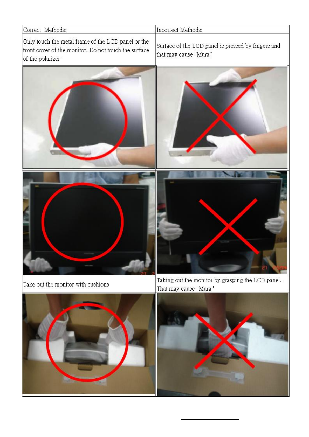
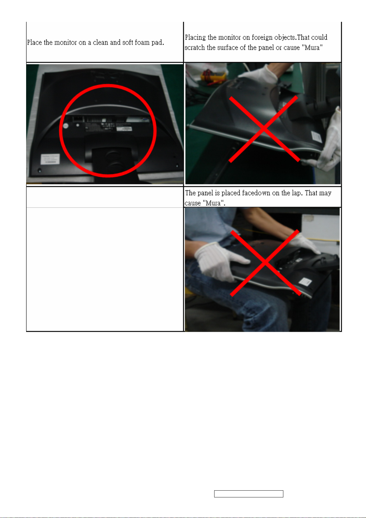
4. Handling and Placing Methods
ViewSonic Corporation Confidential - Do Not Copy VG721m-2
2
ViewSonic Corporation Confidential - Do Not Copy VG721m-2
3
2. Specification
A
1. INTPRODUCTION
Product Name ViewSonic VG721m
Oracle item# VG721M-2
Model Number VS11353
OSD Languages
TFT LCD Panel and Model #
English, French, German, Italian, Spanish, Finnish,
Japanese, Traditional Chinese, Simplified Chinese
st
1
Source: Innolux MT170EN01 V.7
nd
Source: Innolux MT170EN01 V.9
2
Scalar MST TSUM56AL-LF-1
Input Signal Analog x1
Sync Compatibility Separate Sync / Composite Sync / SOG
Adapter Internal Power Board
Power Cable
nalog Cable (1.8 m, black), with PC 2001 and Hot
Plug Detect &DDC
refer to APPENDIX B: Power Cable
(Detached cable; refer the Appendix A)
Yes,
Yes
DVI-D Cable(1.8m, black) with PC 2001 No
Audio Cable(1.8m, black) with PC 2001 Yes
MIC Cable(1.8m, black) with PC 2001 No
USB Cable (V2.0) No
ViewSonic CD Wizard
ViewSonic Quick Start Guide
Arabic, English, Finnish, Spanish, German, Italian,
Japanese, Swedish, Polish, Korean, Portuguese, Russian,
Turkish , French, Czech, Hungarian, Simplified Chinese,
Traditional Chinese
PerfectSuite CD No
Screen Protector Mylar Yes
Foot Protector plastic No
Service Insert For Region code = M units only
Response Time Sticker For Region code = M/E/U/G units only
Warranty Sticker For Region code = G units only
Warranty Card For Region code = G units only
Carton Sticker For Region code = G units only
PE bag of Carton For Region code = G units only
ViewSonic Corporation Confidential - Do Not Copy VG721m-2
4
2 GENERAL specification
Test Resolution & Frequency 1280x1024@60Hz
Test Image Size Full Size
Contrast and Brightness Controls
Factory Default:
Contrast = 70%, Brightness = 100%
3 VIDEO INTERFACE
Analog Input Connector DB-15 (Analog), refer the appendix A
Video Cable Strain Relief
Video Cable Connector DB-15 Pin out Compliant DDC 1/2B
Video Signals
Video Impedance 75 Ohms (Analog)
Maximum PC Video Signal 950 mV with no damage to monitor
Maximum Mac Video Signal 1250 mV with no damage to monitor
DDC 1/2B Compliant with Revision 3
Sync Compatibility Separate Sync/Composite Sync/ SOG,
Video Compatibility
Equal to twice the weight of the monitor for five
minutes
Video RGB (Analog) – Separate Sync/Composite
Sync/ SOG,
Shall be compatible with all PC type computers,
Macintosh computers, and after market video cards
640 x 350, 640 x 400, 640 x 480, 720 x 400, 720 x
Resolution Compatibility
Exclusions Not compatible with interlaced video
480,800 x 600, 832 x 624, 1024 x 768, 1152 x 864,
1152 x 870, 1152 x 900, 1280 x 768,1280 x 960,
1280 x 1024,1440x900
4 POWER SUPPLY
Internal Power Supply Part Number:ILPI-023
Input Voltage Range 90 to 264 VAC
Input Frequency Range 47 to 63 Hertz
Short Circuit Protection Output can be shorted without damage
Over Current Protection 5.0 A typical at 14.0 VDC
Leakage Current 3.5mA (Max) at 254VAC / 60Hz
Efficiency 80% typical at 115VAC Full Load
Fuse Internal and not user replaceable
Power Output 38 Watts (typ)
Max Input AC Current 1.5 Arms @ 90VAC, 0.75 Arms @180VAC
Inrush Current (Cold Start) 50 A @ 115VAC, 90 A (max) @ 230VAC
Power Supply Cold Start Shall start and function properly when under full load,
ViewSonic Corporation Confidential - Do Not Copy VG721m-2
5
with all combinations of input voltage, input
frequency, and operating temperature
Shall be able to withstand an ANSI/IEEE
Power Supply Transient Immunity
Power Supply Line Surge Immunity
Power Supply Missing Cycle Immunity
Power Supply Acoustics
US Type Power Cable
C62.41-1980 2000V 200 ampere ring wave transient
test with no damage
Shall be able to withstand 1.5 times nominal line
voltage for one cycle with no damage
Shall be able to function properly, without reset or
visible screen artifacts, when ½ cycle of AC power is
randomly missing at nominal input
The power supply shall not produce audible noise
that would be detectable by the user. Audible shall
be defined to be in compliance with ISO 7779 (DIN
EN27779:1991) Noise measurements of machines
acoustics. Power Switch noise shall not be
considered
Separate 3-prong NEMA 5-15P type plug. Length =
1.8m. Connects to display.
Color = Black
Schuko CEE7-7 type plug.
European Type Power Cable
CCC Type Power Cable
PSE Type Power Cable
Power Saving Operation(Method) VESA DPMS Signaling
Power Consumption
Recovery Time On Mode = N/A, Active Off < 3 sec
Length = 1.8m, Connects to display.
Color = Black
Separate 3-prong type plug.
Length = 1.8m. Connects to display.
Color = Black
Separate 2-prong NEMA 1-15P type plug. Length =
1.8m. Connects to display.
Color = Black
On Mode <42 W (max)
Off Mode< 1W
5 ELECTRICAL REQUIREMENT
Horizontal / Vertical Frequency
Horizontal Frequency
Vertical Refresh Rate
Maximum Pixel Clock 135 MHz
24 – 82 kHz
50 – 75* Hz.
Sync Polarity Independent of sync polarity.
ViewSonic Corporation Confidential - Do Not Copy VG721m-2
6
Timing Table
Item Timing
Analog
Separated
Composite
SOG
Digital - TMDS
Remark
1 640 x 350 @ 70 Hz, 31.5 KHz
2 640 x 400 @ 60 Hz, 31.5 KHz
3 640 x 400 @ 70 Hz, 31.5 KHz
4 640 x 480 @ 50 Hz, 24.7 KHz
5 640 x 480 @ 60 Hz, 31.5 KHz
6 640 x 480 @ 67 Hz, 35 KHz
7 640 x 480 @ 72 Hz, 37.9 KHz
8 640 x 480 @ 75 Hz, 37.5 KHz
9 720 x 400 @ 70 Hz, 31.5 KHz
10 720 x 480 @ 60 Hz, 31.5 KHz
11 720 x 576 @ 50 Hz, 31.3 KHz
12 800 x 600 @ 56 Hz, 35.1 KHz
13 800 x 600 @ 60 Hz, 37.9 KHz
14 800 x 600 @ 72 Hz, 48.1 KHz
15 800 x 600 @ 75 Hz, 46.9 KHz
16 832 x 624 @ 75 Hz, 49.7 KHz
DMT
DMT
For MAC
DMT
DMT
DTV
DTV
DMT
DMT
DMT
DMT
MAC
17 1024 x 768 @ 50 Hz, 39.6 KHz
18 1024 x 768 @ 60 Hz, 48.4 KHz
19 1024 x 768 @ 70 Hz, 56.5 KHz
21 1024 x 768 @ 75 Hz, 60 KHz
23 1152 x 864 @ 75 Hz, 67.5 KHz
24 1152 x 870 @ 75 Hz, 68.7 KHz
25 1152 x 900 @ 67 Hz, 62.5 KHz
26 1280 x 720 @ 50 Hz, 37.5 KHz
27 1280 x 720 @ 60 Hz, 45 KHz
28 1280 x 768 @ 50 Hz, 39.6 KHz
29 1280 x 768 @ 60 Hz, 47.8 KHz
30 1280 x 768 @ 75 Hz, 60.3 KHz
31 1280 x 960 @ 50 Hz, 49.4 KHz
32 1280 x 960 @ 60 Hz, 59.7 KHz
33 1280 x 960 @ 75 Hz, 75.2 KHz
34 1280 x 1024 @ 50 Hz, 52.7 KHz
DMT
DMT
DMT
DMT
For MAC
For SUN
DTV
DTV
DMT;
DMT;
DMT
35 1280 x 1024 @ 60 Hz, 64 KHz
36 1280 x 1024 @ 75 Hz, 80 KHz
37 1440 x 900 @ 60 Hz 55.9 KHz
DMT
DMT
DMT
ViewSonic Corporation Confidential - Do Not Copy VG721m-2
7

*1. Tolerance ≧ ±2KHz (if no overlapping issue)
*2. Any timing not in the list, it should display as normal or show on “OUT OF RANGE” OSD message without
blanking.
*3. The image quality of 85Hz mode might be worse than 75Hz.
Primary Presets
1280x1024 @ 60Hz
User Presets
Number of User Presets (recognized timings) Available: 10 presets total in FIFO configuration
Changing Modes
● Maximum Mode Change Blank Time for image stability : 5 seconds (Max), excluding “Auto
Adjust” time
● Under DOS mode (640 x 350, 720 x 400 & 640 x 400), it should recall factory setting when
execute “Auto Adjust”
● The monitor needs to do “Auto Adjust” the first time a new mode is detected
(see section “0-Touch™ Function Actions”)
● While running Change Mode, Auto Adjust or Memory Recall, the image shall blank
ViewSonic Corporation Confidential - Do Not Copy VG721m-2
8
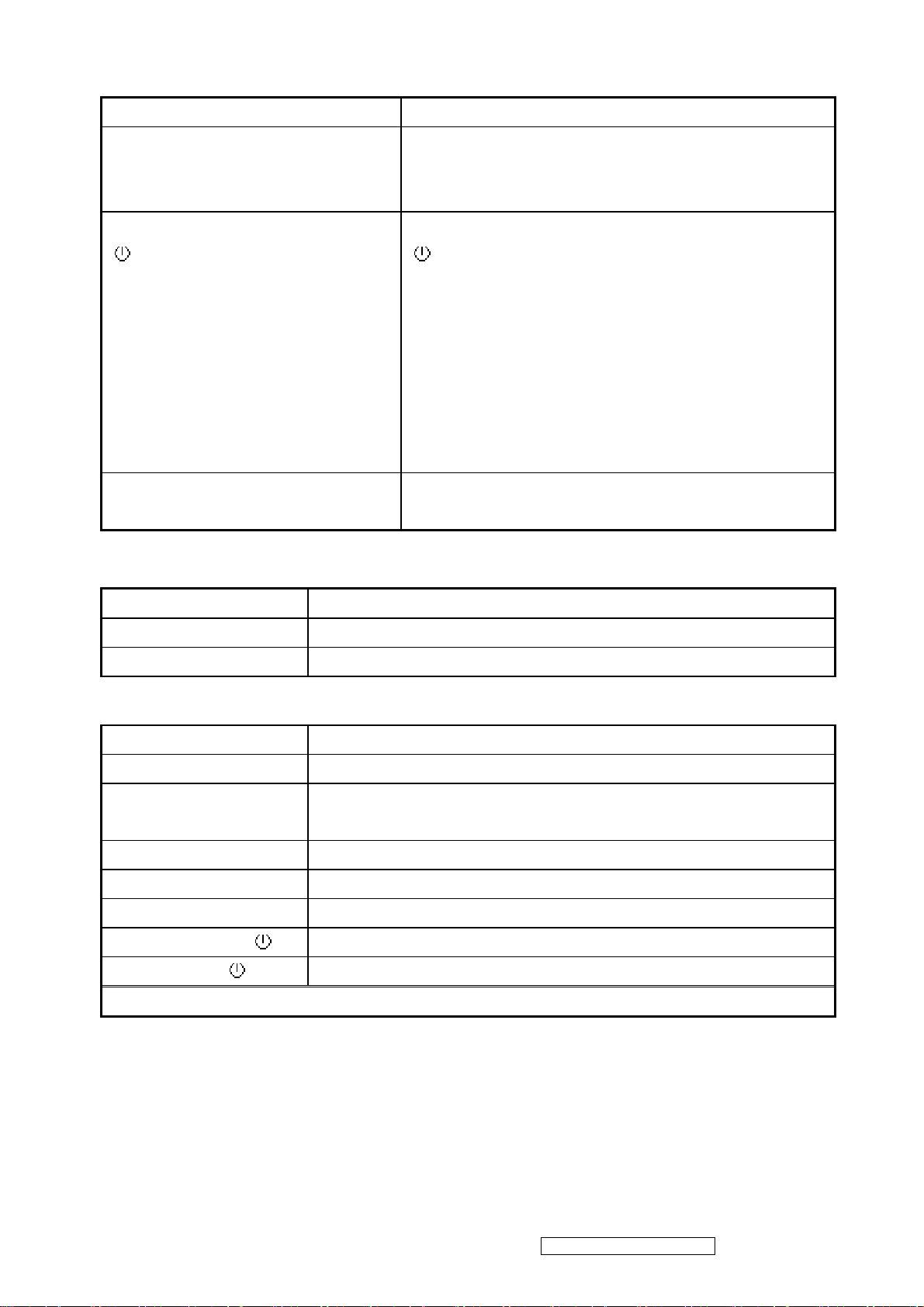
6 FRONT PANEL CONTROLS AND INDICATORS
Front Panel Hardware Controls
Power Switch (Front Head) Power Control, soft Power Switch.
Power LED (Front Head) Blue – ON
Orange – Power Saving Mode
Dark = Soft Power Switch OFF
Front Panel Controls (Head)
[ ] [ 1 ] [ 2 ] [▲] [▼]
[;X] Mute
[ ] Power
[ 1 ] BUTTON 1
[ 2 ] Button 2
[▲] UP ARROW BUTTON
[▼] DOWN ARROW BUTTON
Note: Power Button, Button 1 and Button 2 must
be one-shot logic operation. (i.e. there should be
no cycling)
Reaction Time OSD must fully appear within 0.5s after pushing
Button 1
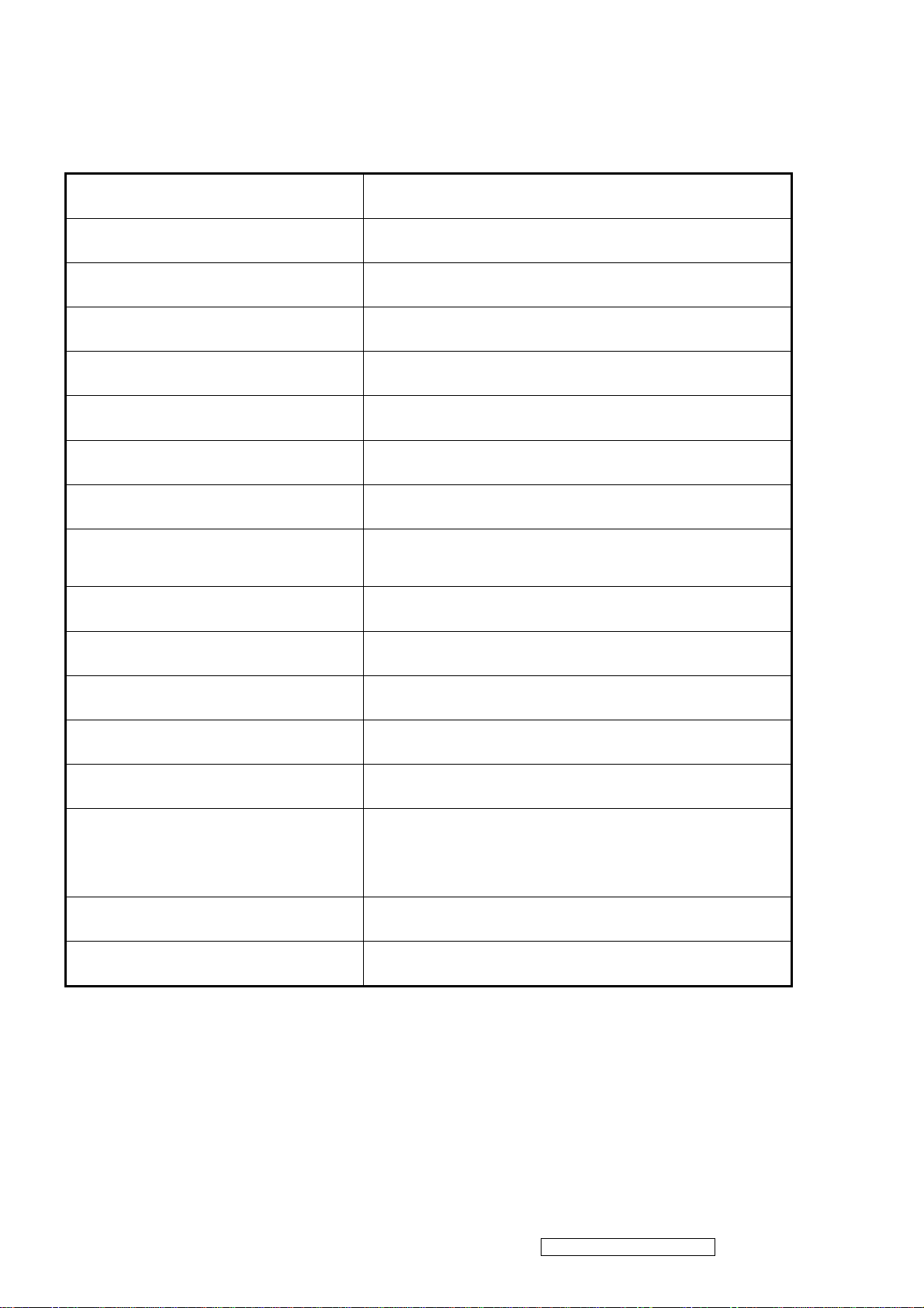
Short Cuts Function from the button(s)
[1] Main Menu
[2] Auto Image Adjust
[▼] Brightness adjust
[▲] Contrast adjust
[▼]+ [▲] recall both of Contrast and Brightness to default
[1] + [2] toggle 720x400 and 640x400 mode when input 720x400 or
640x400 mode
[1] + [▼] + [▲] White Balance. (Not shown on user’s guide)
[1] + [▼] Power Lock
[1] + [▲] OSD Lock
No signal + [2] + [ ] Burning mode
Signal + [2] + [ ] Factory Mode
Remark : All the short cuts function are only available while OSD off
ViewSonic Corporation Confidential - Do Not Copy VG721m-2
9
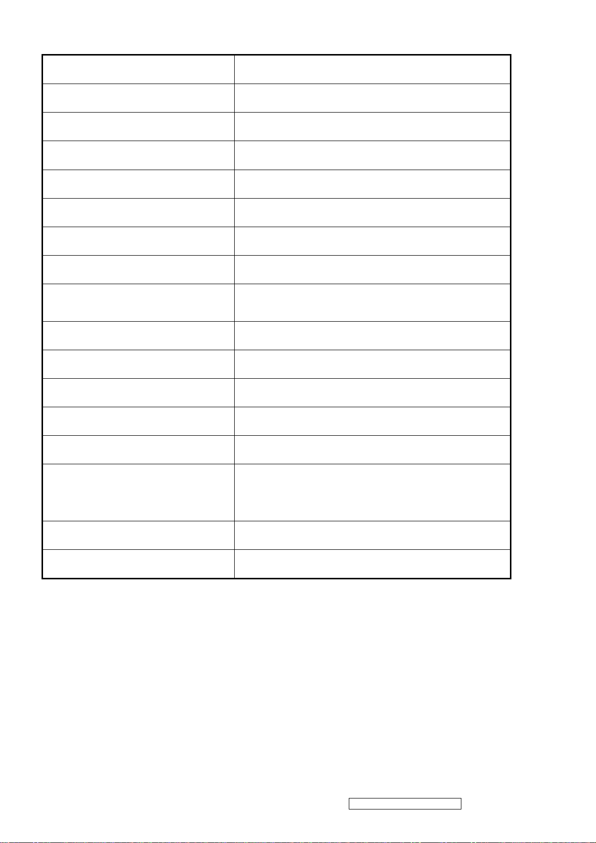
7 TFT LCD PANEL
Panel Characteristics :
1st Source Panel
Model number Innolux MT170EN01 V.7
Type Active Matrix TFT, TN technology
Active Size 17” (337.9mm x 270.3mm)
Pixel Arrangement RGB Vertical Stripe
Pixel Pitch 0.264 mm
Glass Treatment Anti-Glare, Hard coating (3H)
# of Backlights 4 CCFL
Backlight Life 50000 Hrs (Min)
Luminance (Center) –
CT = 6500K,
Contrast/ Brightness = Max
280 cd/m2 (Typ after 30 minute warm up)
250 cd/m2 (Min after 30 minute warm up)
Brightness Uniformity (13 points) 80 % (Typ) / 75 % (Min)
Contrast Ratio
600 :1 (Typ)
500 : 1 (Min)
Color Depth 16.2 million colors (6+2 bit panel)
Horizontal Viewing Angle
Vertical Viewing Angle
Response Time
150 degrees (Typ) / 130 degrees (Min) @ CR>10
170 degrees (Typ) / 150 degrees (Min) @ CR>5
135 degrees (Typ) / 115 degrees (Min) @ CR>10
155 degrees (Typ) / 135 degrees (Min) @ CR>5
On-Off
10%-90% @ Ta=25°C 8ms (Typ) / 16ms (Max)
Mercury 3.0 mg per lamp
Panel Defects Please see Panel Quality Specifications.
*Over 50% units of shipment shall be equal or better than the Typical value above.
ViewSonic Corporation Confidential - Do Not Copy VG721m-2
10
2nd Source Panel
Model number Innolux MT170EN01 V.9
Type Active Matrix TFT, TN technology
Active Size 17” (337.9mm x 270.3mm)
Pixel Arrangement RGB Vertical Stripe
Pixel Pitch 0.264 mm
Glass Treatment Anti-Glare, Hard coating (3H)
# of Backlights 4 CCFL
Backlight Life 50000 Hrs (Min)
Luminance (Center) –
CT = 6500K,
Contrast/ Brightness = Max
300 cd/m2 (Typ after 30 minute warm up)
250 cd/m2 (Min after 30 minute warm up)
Brightness Uniformity (13 points) 80 % (Typ) / 75 % (Min)
Contrast Ratio 800 :1 (Typ)
600 : 1 (Min)
Color Depth 16.7 million colors (6 bit + Hi-FRC)
Horizontal Viewing Angle
Vertical Viewing Angle
Response Time
10%-90% @ Ta=25°C
Mercury
160 degrees (Typ) / 140 degrees (Min) @ CR>10
170 degrees (Typ) / 150 degrees (Min) @ CR>5
160 degrees (Typ) / 140 degrees (Min) @ CR>10
170 degrees (Typ) / 150 degrees (Min) @ CR>5
On-Off
5ms (Typ) / 10ms (Max)
3.0 mg per lamp
Panel Defects Please see Panel Quality Specifications.
*Over 50% units of shipment shall be equal or better than the Typical value above.
ViewSonic Corporation Confidential - Do Not Copy VG721m-2
11
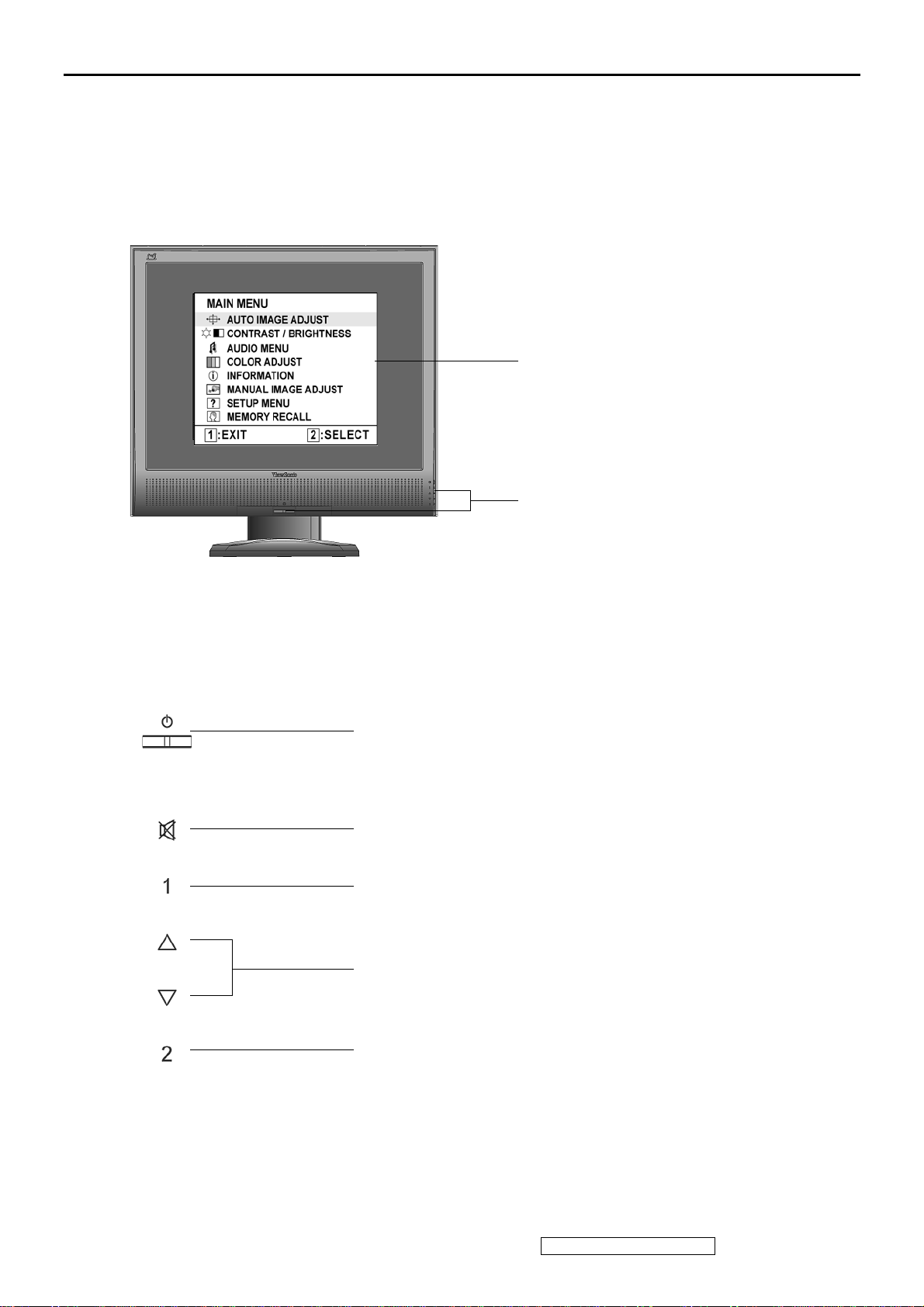
3. Front Panel Function Control Description
Adjusting the Screen Image
Use the buttons on the front control panel to display and adjust the OSD controls which display
on the screen. The OSD controls are explained at the top of the next page and are defined in
“Main Menu Controls” on page 10.
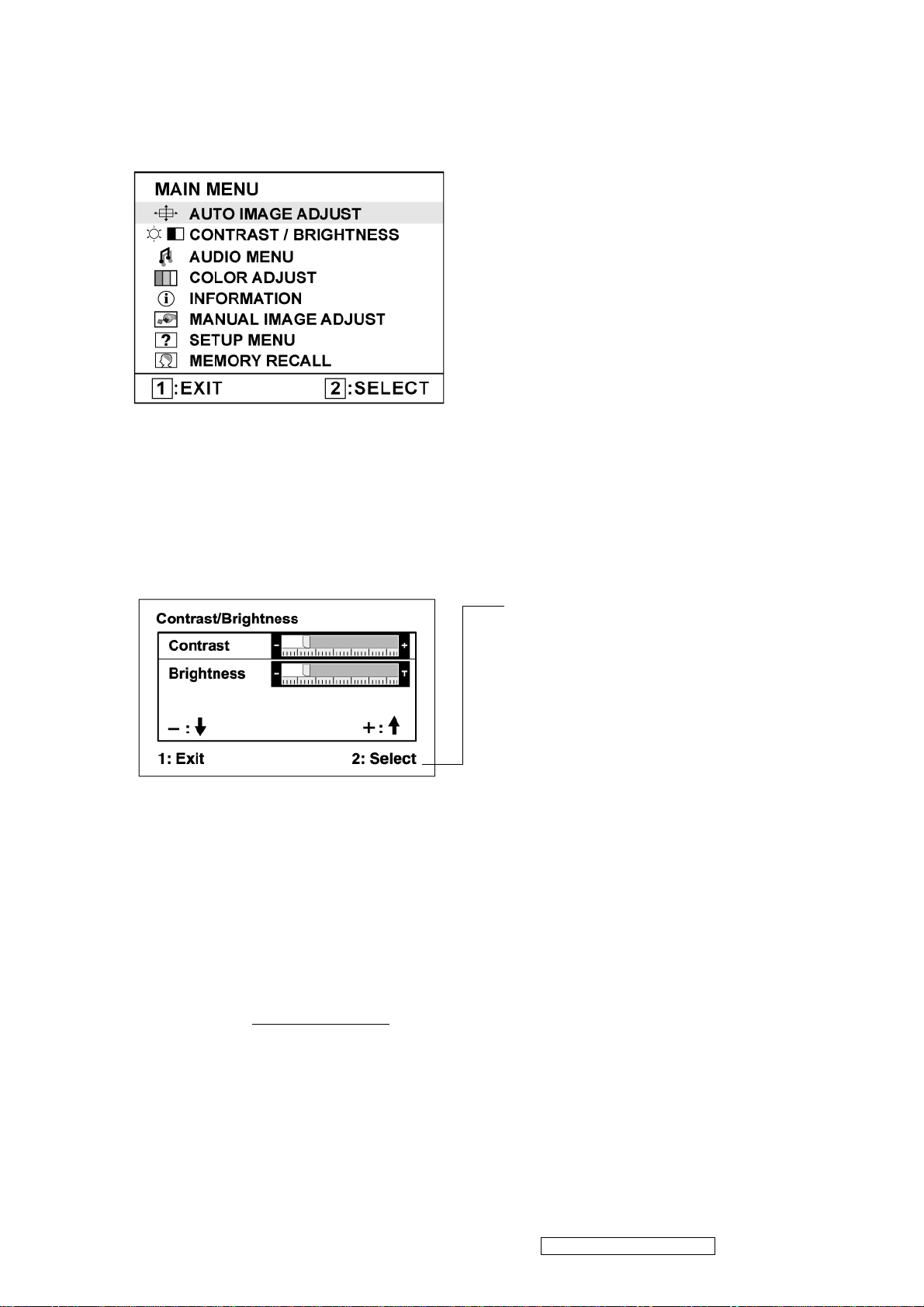
Main Menu
with OSD controls
Front Control Panel
shown below in detail
Standby Power On/Off
Power light
Blue = ON
Orange = Power Saving
Audio Mute button turns the sound off
Displays the Main Menu or exits the control screen and saves
adjustments.
Scrolls through menu options and adjusts the displayed control.
Also a shortcut to display the Contrast adjustment control screen.
Displays the control screen for the highlighted control.
Also toggles between two controls on some screens.
ViewSonic Corporation Confidential - Do Not Copy VG721m-2
12
Do the following to adjust the display setting:
1. To display the Main Menu, press button [1].
NOTE: All OSD menus and adjustment screens disappear automatically after about 15
seconds. This is adjustable through the OSD timeout setting in the setup menu.
2. To select a control to adjust, pressSorTto scroll up or down in the Main Menu.
3. After the desired control is selected, press button [2]. A control screen like the one shown
below appears.
The command line at the bottom of the
control screen tells what to do next from
this screen. You can toggle between control
screens, adjust the selected option, or exit
the screen.
4. To adjust the setting, press the up S or down T buttons.
5. To save the adjustments and exit the menu, press button [1] twice.
The following tips may help you optimize your display:
• Adjust the computer's graphics card so that it outputs a 1280 x 1024 @ 60Hz video signal to
the LCD display. (Look for instructions on “changing the refresh rate” in the graphics card's
user guide.)
• If necessary, make small adjustments using H. POSITION and V. POSITION until the
screen image is completely visible. (The black border around the edge of the screen should
barely touch the illuminated “active area” of the LCD display.)
ViewSonic Corporation Confidential - Do Not Copy VG721m-2
13
Main Menu Controls
Adjust the menu items shown below by using the up S and down T buttons.
Control Explanation
Auto Image Adjust sizes and centers the screen image automatically.
Contrast adjusts the difference between the image background (black level)
and the foreground (white level).
Brightness adjusts background black level of the screen image.
Audio Adjust
Vol ume increases the volume, decreases the volume, and mutes the audio.
Mute temporarily silences audio output.
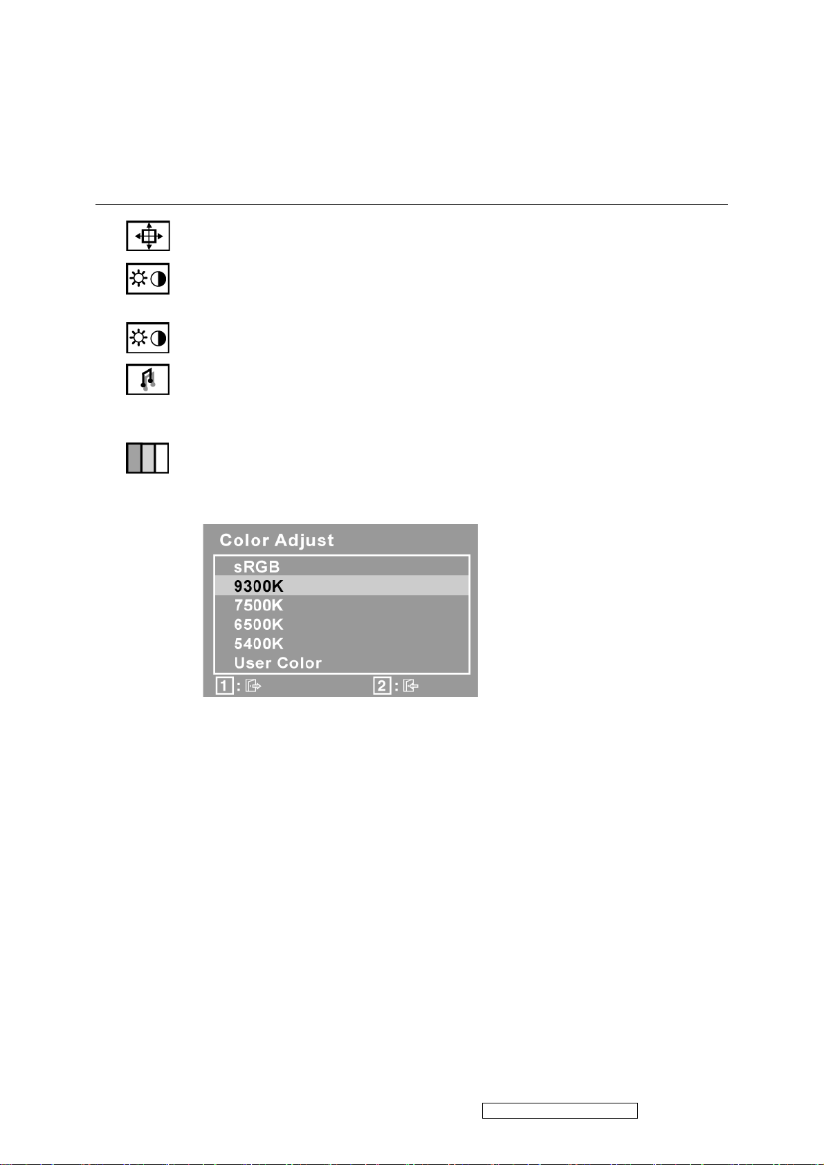
Color Adjust provides several color adjustment modes, including preset color
temperatures and a User Color mode which allows independent adjustment of
red (R), green (G), and blue (B). The factory setting for this product is 6500K
(6500 Kelvin).
sRGB-This is quickly becoming the industry standard for color management,
with support being included in many of the latest applications. Enabling this
setting allows the LCD display to more accurately display colors the way they
were originally intended. Enabling the sRGB setting will cause the Contrast and
Brightness adjustments to be disabled.
9300K-Adds blue to the screen image for cooler white (used in most office
settings with fluorescent lighting).
7500K-Adds blue to the screen image for cooler white (used in most office
settings with fluorescent lighting).
6500K-Adds red to the screen image for warmer white and richer red.
5400K-Adds green to the screen image for a darker color.
ViewSonic Corporation Confidential - Do Not Copy VG721m-2
14
Control Explanation
User Color Individual adjustments for red (R), green (G), and blue (B).
1. To select color (R, G or B) press button [2].
2. To adjust selected color, pressSandT.
Important: If you select RECALL from the Main Menu when the product is
set to a Preset Timing Mode, colors return to the 6500K factory preset.
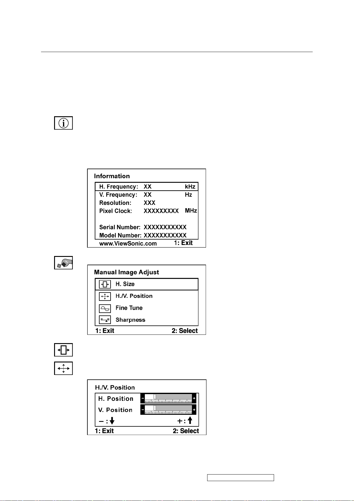
Information displays the timing mode (video signal input) coming from the
graphics card in the computer, the LCD model number, the serial number, and
the ViewSonic® website URL. See your graphics card’s user guide for
instructions on changing the resolution and refresh rate (vertical frequency).
NOTE: VESA 1280 x 1024 @ 60Hz (recommended) means that the resolution
is 1280 x 1024 and the refresh rate is 60 Hertz.
Manual Image Adjust
H. Size (Horizontal Size) adjusts the width of the screen image.
H./V. Position (Horizontal/Vertical Position) moves the screen image left or
right and up or down.
ViewSonic Corporation Confidential - Do Not Copy VG721m-2
15
Control Explanation
Fine Tune sharpens the focus by aligning text and/or graphics with pixel
boundaries.
NOTE: Try Auto Image Adjust first.
Sharpness adjusts the clarity and focus of the screen image.
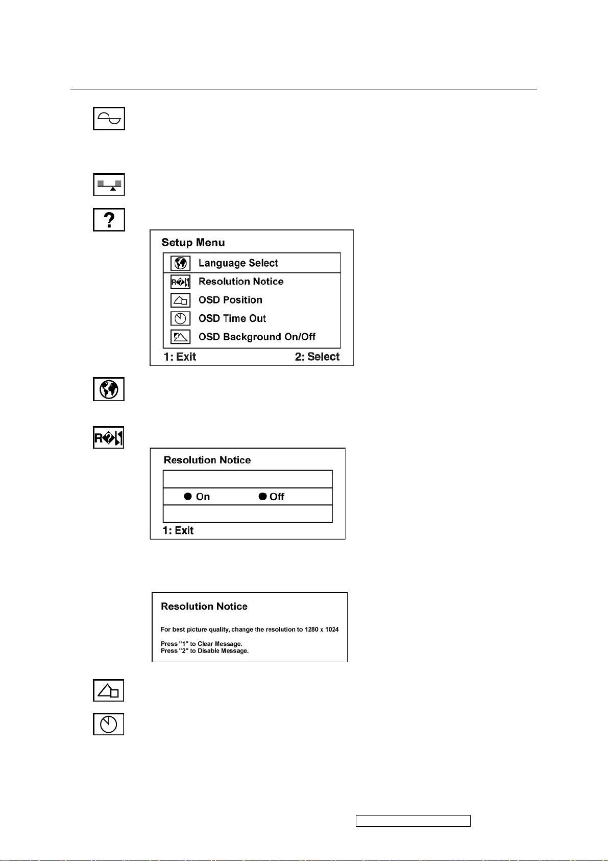
Setup Menu displays the menu shown below:
Language Select allows the user to choose the language used in the menus and
control screens.
Resolution Notice allows the user to enable or disable this notice.
If you enable the Resolution Notice shown above and your computer is set at a
resolution other than 1280 x 1024, the following screen appears.
OSD Position allows the user to move the OSD menus and control screens.
OSD Timeout sets the length of time the OSD screen is displayed. For example,
with a “30 second” setting, if a control is not pushed within 30 seconds, the
display screen disappears.
ViewSonic Corporation Confidential - Do Not Copy VG721m-2
16

Control Explanation
OSD Background allows the user to turn the OSD background On or Off.
Memory Recall returns the adjustments back to factory settings if the display is
operating in a factory Preset Timing Mode listed in the Specifications of this
manual.
ViewSonic Corporation Confidential - Do Not Copy VG721m-2
17
4. Circuit Description
Electronic Circuit Theory
2.1 Switching Mode Power Supply
Switching Mode Power Supply
2.1.1 AC Current Input Circuit
P801 is a connector for connecting AC Power. F801 is a fuse to protect all the circuit. AC input voltage is from
90v to 264V. R820 and R821 joined between two inputting main circuit to prevent man from shock. L801 is
used to clear up low frequency wave. C801 and C806 are used to discharge the waves that L801 produced.
High frequency waves are damped by C801 and C806. D801 is a rectifier which composed of 4 build-in diodes,
it inverts AC to DC.
2.1.2 High Voltage to Low Voltage Control Circuit
C805 is used to smooth the wave from rectifier. IC802 is a highly integrated PWM controller which build-in
power MOSFET. When rectified DC high voltage is applied to the DRAIN pin during start-up, the MOSFET is
initially off, and the CONTROL pin capacitor is charged through a switched high voltage current source
connected internally between the DRAIN and CONTROL pins. When the CONTROL pin voltage Vc reaches
approximately 5.8V, the control circuitry is activated and the soft-start begins. The soft-start circuit gradually
increases the duty cycle of the MOSFET from zero to the maximum value over approximately 10ms. If no
external feedback/supply current is fed into the CONTROL pin by the end of the soft-start, the high voltage
current source is turned off and the CONTROL pin will start discharging in response to the supply current
drawn by the control circuitry.
Resistor R803, R807, R824 and R825 are for line over voltage shutdown(OV) and line under-voltage
detection(UV).
Resistors R801, R805, R822, R823 are for external current limit adjustment. And used to reduce the current
limit externally to a value close to the operating peak current of primary about 1.35A. The mean is power will
protected when the primary current over about 1.35A.
When PWM is turned off, the main current flow will be consumed through D804, and ZD802, This will
prevent MOSFET which built-in IC802 from being damaged under large current impulse and voltage spike.
D806 and C815 to provide internal Auxiliary current to CONTROL pin during normal operation. Otherwise,
error amplifier and feedback current input the CONTROL pin for duty cycle control.
2.1.3 DC_5V and DC_14V Output Circuit
For DC 5V, D805 is used to rectify the inducted current. R806 and C811 are used to store energy when current
is reversed. The parts including C814, C814, C822, C821, B801 and L803 are used to smooth the current
waves.
For DC 14V, D803 is used to rectify the inducted current. R802 and C802
2. 2 Inverter Circuit
2.2.1 Low voltage to high voltage circuit
14VDC provides the power for IC501; the control signals Brightness and ON/OFF come from I/F board.
ON/OFF signal connect to pin10 of IC501 and makes IC501 enable. Brightness signal connect to pin4 of
IC501 and regulates the panel brightness, R526, R529, C505 make up a network of delaying time circuit and
R523, R524 make up a divided voltage network, C504 is used to dump noise. The operation frequency is
ViewSonic Corporation Confidential - Do Not Copy VG721m-2
18
 Loading...