

ViewSonic VG720 - 17"" LCD Monitor, VG920, VS10790, VG720, VS10791 Service Manual
- 1 –
ViewSonic Corporation
Confidential - Do Not Copy VG720
Manufacture Date: Aug-10-05
Service Manual
ViewSonic VG720
Model No VS10791
17” Color TFT LCD Display
- 2 –
ViewSonic Corporation
Confidential - Do Not Copy VG720
Copyright
Copyright © 2005 by ViewSonic Corporation. All rights reserved. No part of this publication
may be reproduced, transmitted, transcribed, stored in a retrieval system, or translated into
any language or manual or otherwise, without the prior written permission of ViewSonic
Corporation.
Disclaimer
ViewSonic makes no representation or warranties, either expressed or implied, with
respect to the contents hereof and specifically disclaims any warranty of merchantability of
fitness for any particular purpose. Further, ViewSonic reserves the right to revise this
publication and to make changes from time to time in the contents hereof without
obligation of ViewSonic to notify any person of such revision or changes.
Trademarks
Optiquest is a registered trademark of ViewSonic Corporation.
ViewSonic is a registered trademark of ViewSonic Corporation.
All other trademarks used within this document are the property of their respective owners.
Revision History
Revision Date Description of changes Approval
A00 Aug-10-05 Initial Release YG.WANG
A01 Dec-28-05
Update the Handing and Placing Methods
and the Circuit Description and the
Adjustment Procedure
YG.WANG
- 3 –
ViewSonic Corporation
Confidential - Do Not Copy VG720
TABLE OF CONTENTS
1. Precautions And Safety Notices 4
2. Specification 7
3. Front Panel Control And Indicators 10
4. Circuit Description 16
5. Adjustment Procedure 23
6. Troubleshooting Flow Chart 43
7. Recommended Spare Parts List 44
8. Exploded Diagram And Spare Parts List 61
9. Disassemble Process 64
10. Block Diagram 71
11. Schematic Diagram 72
12. PCB Layout Diagram 79

- 4 –
ViewSonic Corporation
Confidential - Do Not Copy VG720
1. Precautions And Safety Notices
1.1 SAFETY PRECAUTIONS
This monitor is manufactured and tested on a ground principle that a user’s safety comes
first. However, improper use or installation may cause damage to the monitor as well as
the user. Carefully go over the following WARNINGS before installing and keep this guide
handy.
WARNINGS
.This monitor should be operated only at the correct power sources indicated on the label
on the rear end of the monitor. If you’re unsure of the power supply in your residence,
consult you local dealer or power company.
.Use only the special power adapter that comes with this monitor for power input.
.Do not try to repair the monitor your self as it contains no user-serviceable parts. This
monitor should only be repaired by a qualified technician.
.Do not remove the monitor cabinet. There is high-voltage parts inside that may cause
electric shock to human bodies, even when the power cord is unplugged.
.Stop using the monitor if the cabinet is damaged. Have it checked by a service technician.
.Put your monitor only in a clean, dry environment. If it gets wet, unplug the power cable
immediately and consult your service technician.
.Always unplug the monitor before cleaning it .Clean the cabinet with a clean, dry cloth.
Apply non-ammonia based cleaner onto the cloth, not directly onto the glass screen.
.Keep the monitor away from magnetic objects, motors, TV sets, and transformer.
.Do not place heavy objects on the monitor or power cord.
1.2 PRODUCT SAFETY NOTICE
Many electrical and mechanical parts in this chassis have special safety visual inspections
and the protection afforded by them cannot necessarily be obtained by using replacement
components rated for higher voltages, wattage, etc. Before replacing any of these
components read the parts list in this manual carefully. The use of substitute replacement
parts which do not have the same safety characteristics as specified in the parts list may
create shock, fire ,or other hazards.
1.3 SERVICE NOTES
1. When replacing parts or circuit boards, clamp the lead wires around terminals before
soldering.
2. When replacing a high wattage resistor(more than 1W of metal oxide film resistor) in
circuit board, keep the resistor about 5mm away from circuit board.
3. Keep wires away from high voltage, high temperature components and sharp edges.
4. Keep wires in their original position so as to reduce interference.
5. Usage of this product please refer to also user’s manual.
- 5 –
ViewSonic Corporation
Confidential - Do Not Copy VG720
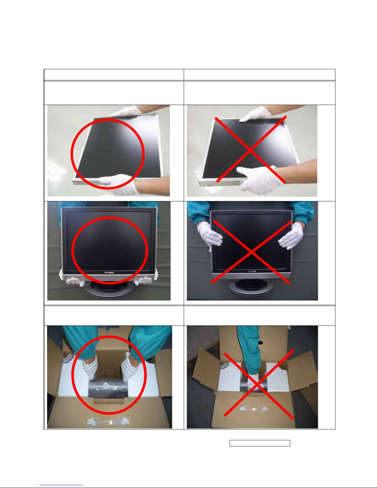
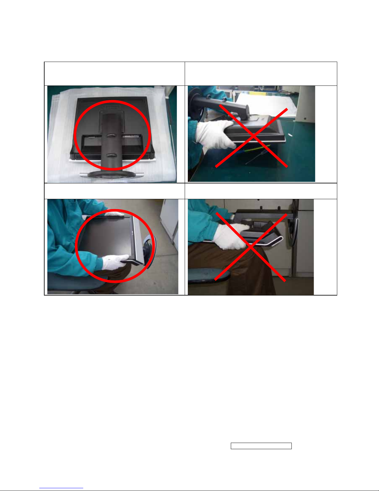
1.4 HANDING AND PLACING METHODS
Correct Methods: Incorrect Methods:
Only touch the metal frame of the LCD
panel or the front cover of the monitor. Do
not touch the surface of the polarizer.
Surface of the LCD panel is pressed by fingers
and that may cause “Mura.”
Take out the monitor with cushions
Taking out the monitor by grasping the LCD
panel. That may cause “Mura.”
- 6 –
ViewSonic Corporation
Confidential - Do Not Copy VG720
Place the monitor on a clean and soft foam
pad.
Placing the monitor on foreign objects. That
could scratch the surface of the panel or cause
“Mura.”
Place the monitor on the lap, the panel
surface must be upwards.
The panel is placed facedown on the lap. That
may cause “Mura.”

- 7 –
ViewSonic Corporation
Confidential - Do Not Copy VG720
2. Specification
2.1 PRODUCT SPECIFICATIONS
LCD Panel 17.0” TFT
Recommend Resolution 1280 x1024@60Hz
Pixel Dimension 0.264(H) x 0.264(V)mm
LCD Display Color 16.2M Colors (RGB 6-bit+FRC data)
Viewing Angle
Horizontal: 140
°
Vertical: 125 °
Contrast Ratio 600:1 (Typ.)
Brightness 270 cd/㎡(Typ.)
Response Time 8ms(Typ.)
Active Display Area 337.920(H) x 270.336(V)
Maximum Pixel Clock 135 MHz
Horizontal Frequency 30 – 82 kHz
Vertical Refresh Rate 50 – 75 Hz.
Temperature
Operating: 0°C to +40°C
Storage: -20°C to +60°C
Power Management
Energy Star compliant VESA
DPMS compatible
<1 W
Power
Input Voltage : 90V~264V
Consumption: 48 Watts(Max.) 43 Watts(Typ.)
- 8 –
ViewSonic Corporation
Confidential - Do Not Copy VG720
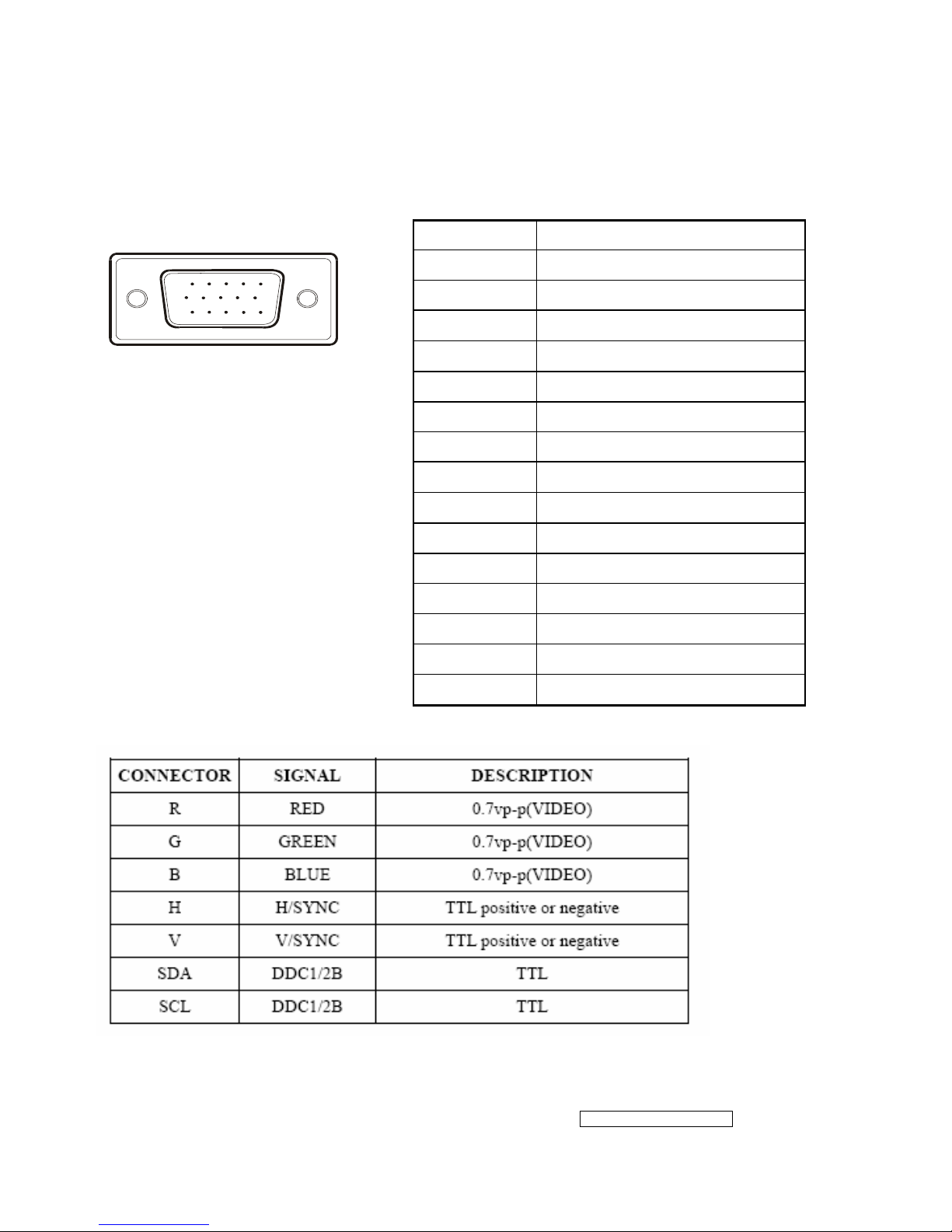
2.2 INTERFACE DESCRIPTION
D-SUB 15 PIN CONNECTOR
15
6
10
11 15
SIGNAL LEVEL
Pin Number Pin Function
1 Red video input
2 Green video input
3 Blue video input
4 No Connection
5 Ground
6 Red video ground
7 Green video ground
8 Blue video ground
9 +5V
10 H/V sync ground
11 No co n ne c t i o n
12 (SDA)
13 Horizontal sync (Composite sync)
14 Vertical sync
15 (SCL)
- 9 –
ViewSonic Corporation
Confidential - Do Not Copy VG720
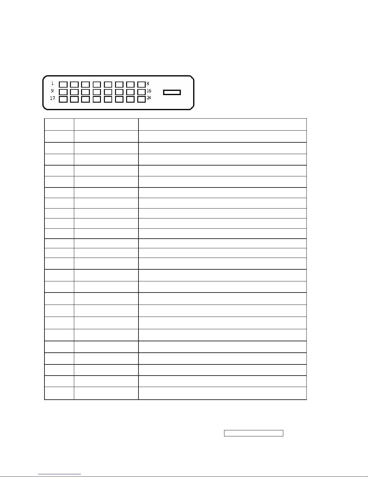
DVI-D 24 PIN CONNECTOR
Pin No. Signal Name Description
1 RX2- TMDS negative differential input, channel 2
2 RX2+ TMDS positive differential input, channel 2
3 GND Logic Ground
4 Reserved 4 Reserved. No connection
5 Reserved 5 Reserved. No connection
6 DDC-CLK DDC2B Clock
7 DDC-DAT DDC2B Data
8 Reserved 8 Reserved. No connection
9 RX1- TMDS negative differential input, channel 1
10 RX1+ TMDS positive differential input, channel 1
11 GND Logic Ground
12 Reserved 12 Reserved. No connection
13 Reserved 13 Reserved. No connection
14 VCCX Power
15 GND Logic Ground
16 SENS SENSE Pin, Pull High
17 RX0- TMDS negative differential input, channel 0
18 RX0+ TMDS positive differential input, channel 0
19 GND Logic Ground
20 Reserved 20 Reserved. No connection
21 Reserved 21 Reserved. No connection
22 GND Logic Ground
23 RXC+ TMDS positive differential input, reference clock
24 RXC- TMDS negative differential input, reference clock
- 10 –
ViewSonic Corporation
Confidential - Do Not Copy VG720
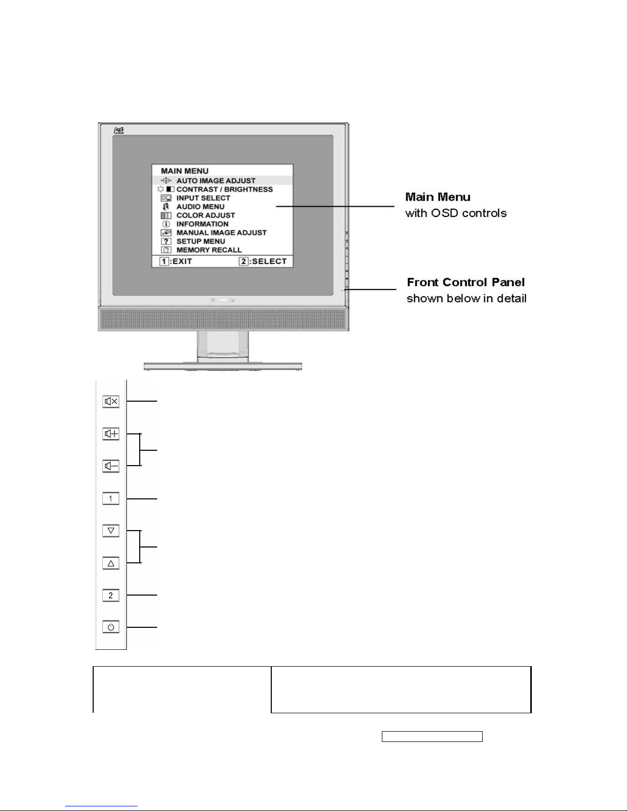
3. Front Panel Function Controls And Indicators
Mute: Audio Mute button turns the sound off
Volume+/ Volume-:Decreases or increases volume
Button 1:Scrolls through menu options and adjusts the displayed
control. Also a shortcut to display the Contrast adjustment control
screen.
[▲]、[▼]:Displays the control screen for the highlighted control. Also
toggles between two controls on some screens. Also a shortcut to toggle
analog and digital connection.
Button 2:Displays the control screen for the highlighted control. Also toggles
between two controls on some screens. Also a shortcut to toggle analog and
digital connection.
Power:Standby Power On/Off
Power LED (Front Head)
Green – ON
Orange – Active Off
Dark = Soft Power Switch OFF
- 11 –
ViewSonic Corporation
Confidential - Do Not Copy VG720
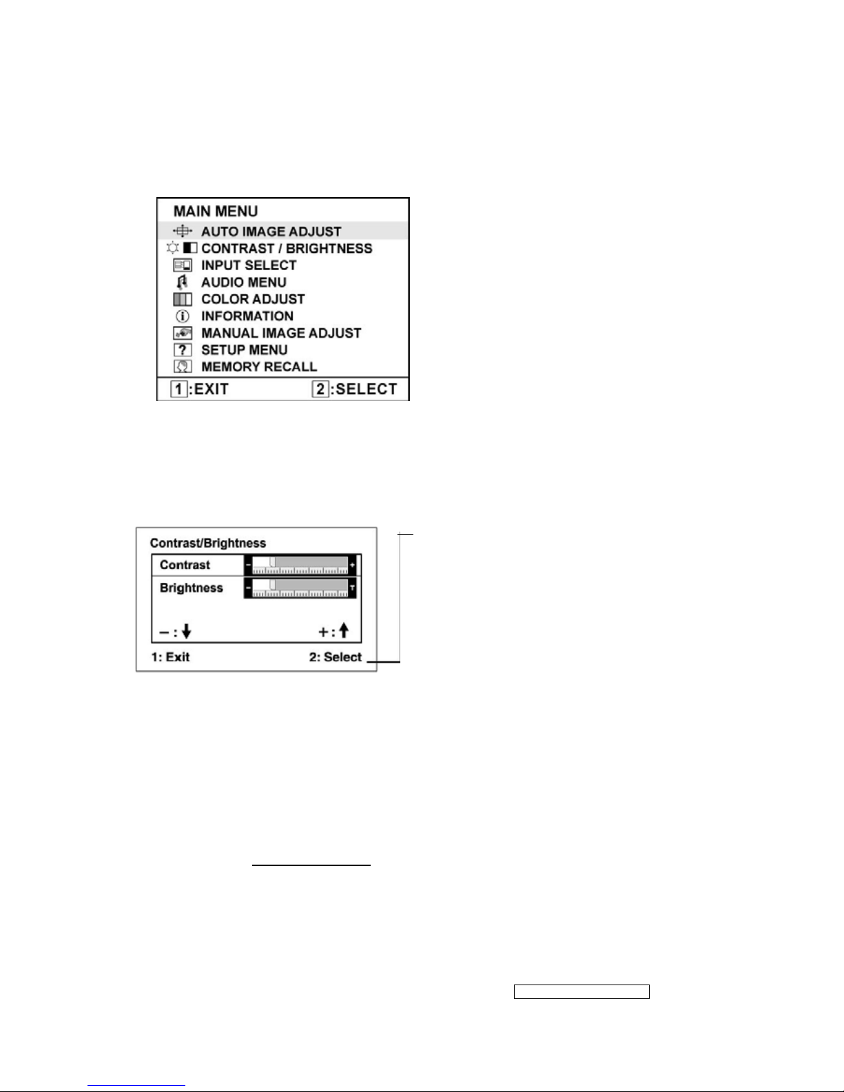
Do the following to adjust the display setting:
1. To display the Main Menu, press button [1].
NOTE: All OSD menus and adjustment screens disappear automatically after about 15
seconds. This is adjustable through the OSD timeout setting in the setup menu.
2. To select a control to adjust, press or ▼ to ▲ scroll up or down in the Main Menu.
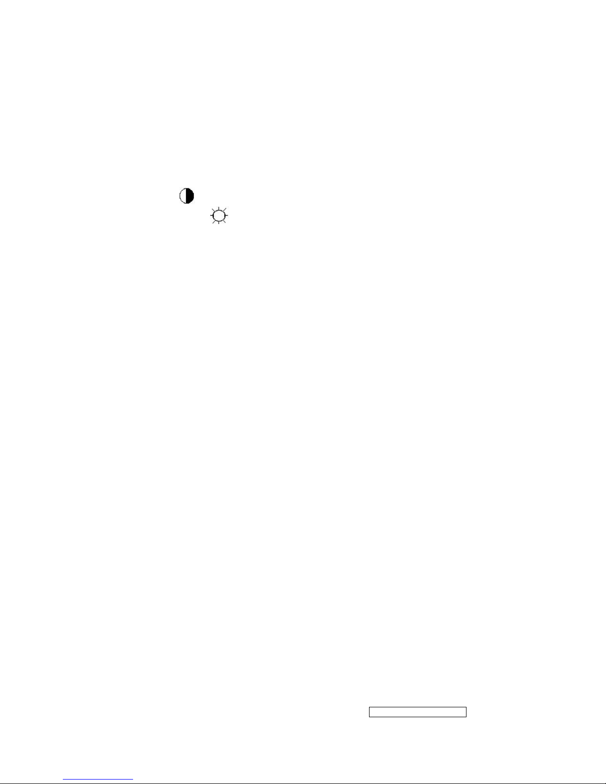
3. After the desired control is selected, press button [2]. A control screen like the one
shown below appears.
The command line at the bottom of the control
screen tells what to do next from this screen.
You can toggle between control screens,
adjust the selected option, or exit the screen.
4. To adjust the setting, press the up ▼ or ▲ down T buttons.
5. To save the adjustments and exit the menu, press button [1] twice.
The following tips may help you optimize your display:
• Adjust the computer's graphics card so that it outputs a 1280 x 1024 @ 60Hz video
signal to the LCD display. (Look for instructions on “changing the refresh rate” in the
graphics card's user guide.)
• If necessary, make small adjustments using H. POSITION and V. POSITION until the
screen image is completely visible
. (The black border around the edge of the screen
should barely touch the illuminated “active area” of the LCD display.)
- 12 –
ViewSonic Corporation
Confidential - Do Not Copy VG720
Main Menu Controls
Adjust the menu items shown below by using the up
and down buttons.
Control
Explanation
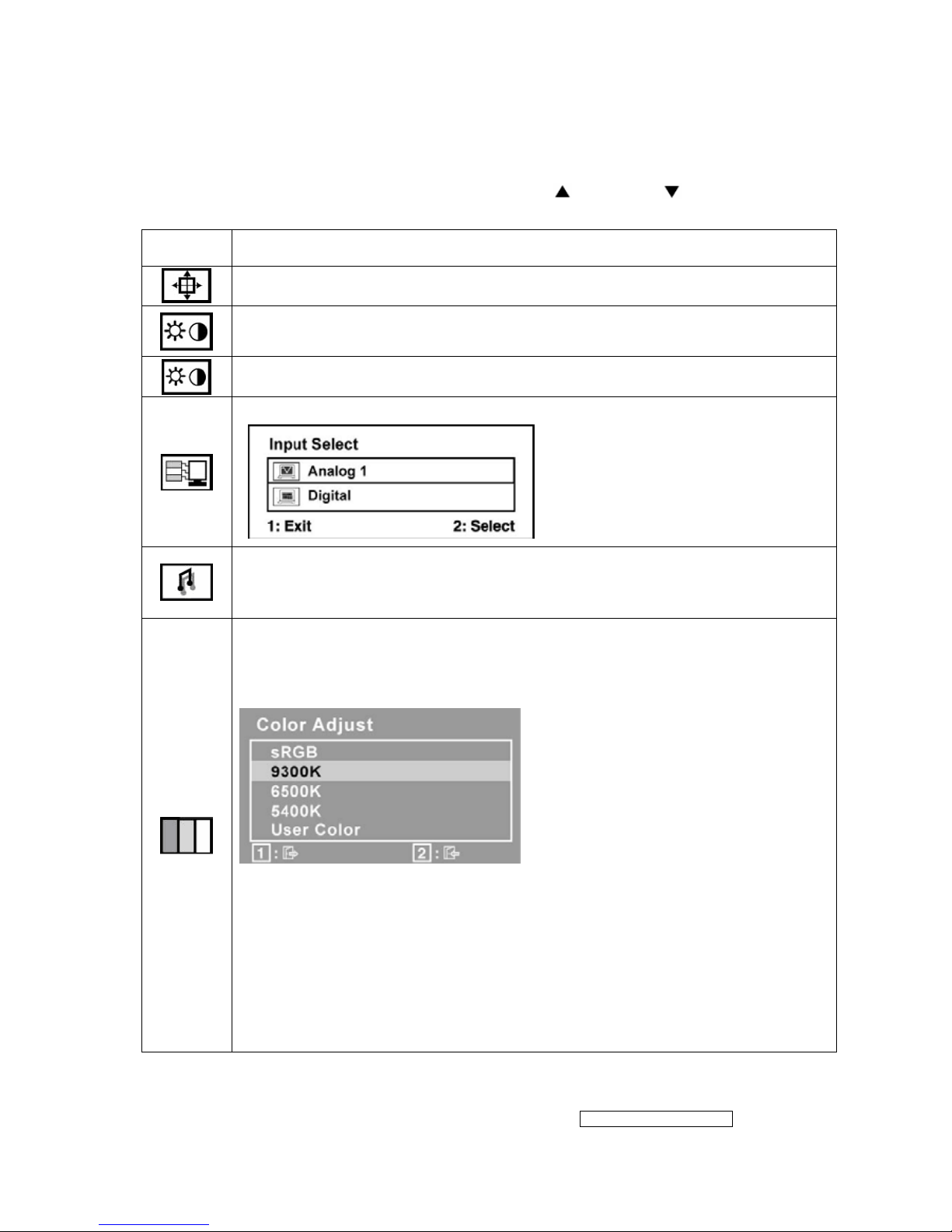
Auto Image Adjust sizes and centers the screen image automatically.
Contrast adjusts the difference between the image background (black level)
and the foreground (white level).
Brightness adjusts background black level of the screen image.
Input Select allows the user to toggle between an analog and a digital signal.
Audio Adjust
Volume increases the volume, decreases the volume, and mutes the audio.
Mute temporarily silences audio output.
Color Adjust provides several color adjustment modes, including preset color
temperatures and a User Color mode which allows independent adjustment of
red (R), green (G), and blue (B). The factory setting for this product is 6500K
(6500 Kelvin).
9300K-Adds blue to the screen image for cooler white (used in most office
settings with fluorescent lighting).
6500K-Adds red to the screen image for warmer white and richer red.
5400K-Adds green to the screen image for a darker color.
User Color Individual adjustments for red (R), green (G), and blue (B).
1. To select color (R, G or B) press button [2].
2. To adjust selected color, press
▼ and ▲.
Important: If you select RECALL from the Main Menu when the product is
set to a Preset Timing Mode, colors return to the 6500K factory preset.
- 13 –
ViewSonic Corporation
Confidential - Do Not Copy VG720
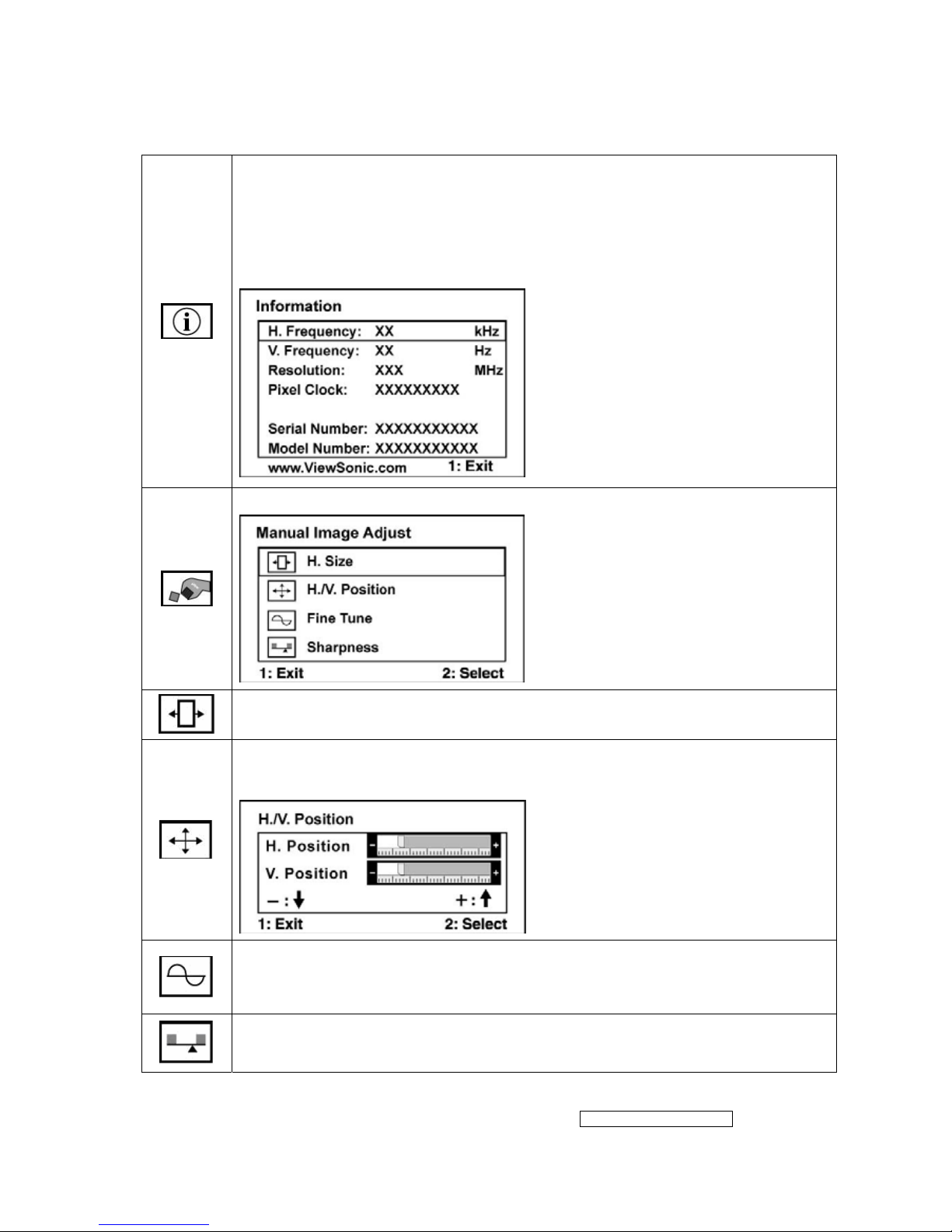
Information displays the timing mode (video signal input) coming from the
graphics card in the computer, the LCD model number, the serial number, and
the ViewSonic
®
website URL. See your graphics card’s user guide for
instructions on changing the resolution and refresh rate (vertical frequency).
NOTE: VESA 1280 x 1024 @ 60Hz (recommended) means that the resolution
is 1280 x 1024 and the refresh rate is 60 Hertz.
Manual Image Adjust Sub-menu
H. Size (Horizontal Size) adjusts the width of the screen image.
H./V. Position (Horizontal/Vertical Position) moves the screen image left or
right and up or down.
Fine Tune sharpens the focus by aligning text and/or graphics with pixel
boundaries.
NOTE: Try Auto Image Adjust first.
Sharpness adjusts the clarity and focus of the screen image.
- 14 –
ViewSonic Corporation
Confidential - Do Not Copy VG720
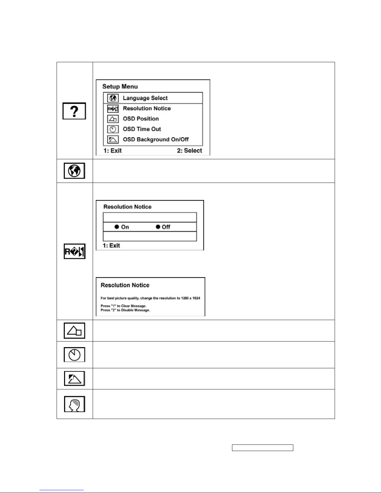
Setup Menu displays the menu shown below:
Language Select allows the user to choose the language used in the menus
and control screens.
Resolution Notice allows the user to enable or disable this notice.
If you enable the Resolution Notice shown above and your computer is set at
a resolution other than 1280 x 1024, the following screen appears.
OSD Position allows the user to move the OSD menus and control screens.
OSD Timeout sets the length of time the OSD screen is displayed. For
example, with a “30 second” setting, if a control is not pushed within 30
seconds, the display screen disappears.
OSD Background allows the user to turn the OSD background On or Off.
Memory Recall returns the adjustments back to factory settings if the display
is operating in a factory Preset Timing Mode listed in the Specifications of this
manual.

- 15 –
ViewSonic Corporation
Confidential - Do Not Copy VG720
SHORT CUTS FUNCTION FROM THE BUTTONS
[1]
Main Menu
[2]
Input toggle (Analog or Digital).
[▼] or [▲]
To immediately activate Contrast menu. It should be
change to Brightness OSD by push button [2]
[▼] + [▲]
recall both of Contrast and Brightness to default
[;+] or [;-]
To immediately activate Volume menu for audio volume.
[;+] + [;X]
Recall volume to default
[1] + [2]
toggle 720x400 and 640x400 mode when input 720x400
or 640x400 mode
[1] + [;X]
White Balance. (Not shown on user’s guide)
[2] + [▼]
• Power Button Lock: Press and hold “[2], & ▼” for 10
seconds. If the power button is pressed the message
Power Button Locked will display for 5 seconds. With or
without this setting, after a power failure, your LCD
display’s power will automatically turn ON when power is
restored.
• Power Button Unlock: Press and hold “[2], & ▼” again
for 10 seconds.
[1] + [▲]
• OSD Lock: Press and hold "[1], & (▲)" for 10 seconds.
If any buttons are pressed the message OSD Locked will
display for 5 seconds.
• OSD Unlock: Press and hold “[1], & ▲” again for 10
seconds.
Remark : All the short cuts function are only available while OSD off
- 16 –
ViewSonic Corporation
Confidential - Do Not Copy VG720
4. Circuit Description
4.1 LCD MONITOR DESCRIPTION
The LCD MONITOR will contain a Main Board, an Power Board, Key Board which
house the flat panel control logic, brightness control logic and DDC.
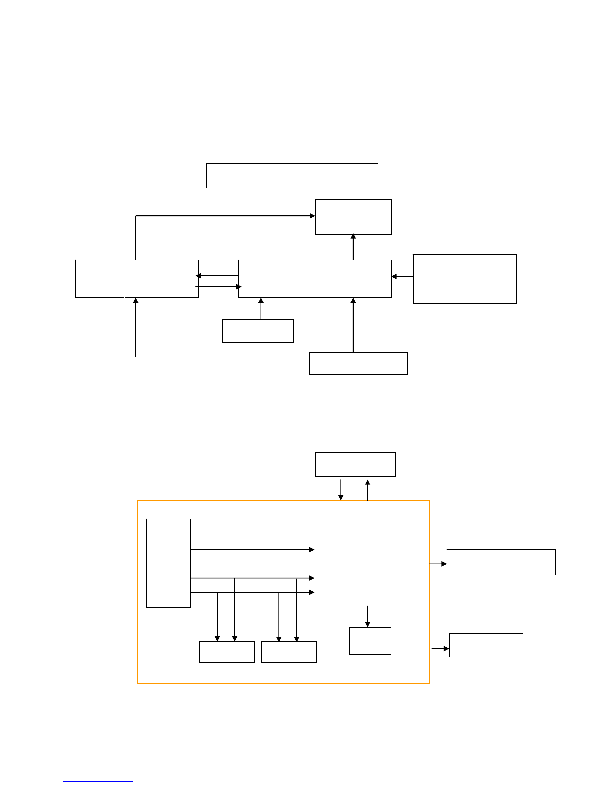
4.2 MAIN BOARD BLOCK FUNCTION DESCRIPTION
The main board contains panel control logic, brightness control logic, DDC and DC
convert DC circuit and so on.
Power Board
(Include: adapter, inverter)
Flat Panel and
CCFL backlight
Main Board
Key Board
RS232 Connector
For white balance
adjustment in factory
mode
HOST Computer
CCFL Drive.
AC-IN
100V-240V
Video signal, DDC
Monitor Block Diagram
R
G
B
H
V
SDA
SCL
OSC
Backlight and Panel
PWPC board
EPROM EPROM
Keyboard
TSUM56AK
- 17 –
ViewSonic Corporation
Confidential - Do Not Copy VG720
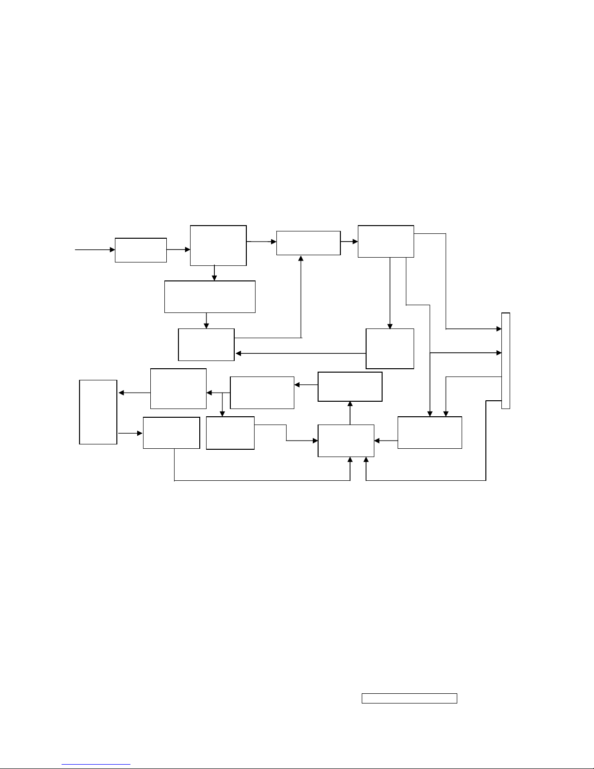
4.3 PWPC BOARD BLOCK FUNCTION DESCRIPTION
PWPC board combines to adapter and inverter, Adapter which commonly consists
of bridge rectifier and filter, start circuit, PWM control circuit, protection circuits and
convert to 12V, 5V DC voltage by input 90V-240V AC voltage that provide power supply
for each chips in the main board and inverter. Inverter is DC TO AC circuit. It changes
the 12v DC of power supply to about 600-800v AC that drives the backlight. It mostly
consists of starting circuit, PWM controller, DC changing circuit, LC surging circuit,
output circuit and protection circuit etc.
AC input
EMI filter
Bridge
Rectifier
and Filter
Start Circuit
R903, R904,R905
PWM
Control IC
Over
Vol tage
Protect
Rectifier
CMOS
ON/OFF
Control
PWM
Control IC
Feedback
Circuit
OSC and
Output
Circuit
DC Convert
Circuit
MOSFET
Q203
Over
Voltage
CN902
Transformer
Lamp
5V
12V
ON/OF
DIM
- 18 –
ViewSonic Corporation
Confidential - Do Not Copy VG720
4.4 INTRODUCTION OF IC
STUM56AK(U401): integrate ADC, OSD, SCALER, MCU, LVDS, convert analog RGB
into digital and room and shrink scaling output to LCD panel.
PIN Function:
AIC1084-33PM (U702): DC power convert, used to 5v convert 3.3v.
LT1117-18(U701): DC power convert, used to 5v convert 3.3v.
Pin Symbol Description
70 SDO SPI flash serial data output; Input w/5V-tolerant
71 CSZ SPI flash chip select; output
72 SCK SPI flash serial select; output
73 SDI SPI flash serial data input; output
65 DDCA_SDA/RS232_TX DDC data for analog interface; 4mA driving
strength/UART transmitter/GPIO; I/O w/5V-tolrant
66 DDCA_SDA/RS232_RX DDC data for analog interface/UART
transmitter/GPIO;Input w/5V-tolrant
36 DDCD_SDA DDC data for DVI interface; 4mA driving strength;
I/O w/5V-tolerant
37 DDCD_SCL DDC clock for DVI interface; Input w/5V-tolerant
19 RST Chip reset; High reset; Input w/5V-tolerant
22 RSTN Chip reset; Low reset; Input w/5W-toerant
11 VCTRL Regulator control; Output
63 HSYNCO Analog HSYNC input
64 VSYNCO Analog VSYNC input
62 REFP Internal ADC top de-coupling pin
61 REFM Internal ADC bottom de-coupling pin
51 REXT
External resistor 390 ohm to AVDD_DVI
21 PWM1 PWM1; 4mA driving strength; Output
29 PWM0 PWM0; 4mA driving strength; Output
4 BYPASS For External Bypass Capacitor
33 XIN Xin; Crystal Oscillator Input
34 XOUT Xout; Crystal Oscillator Output
44、50 AVDD_DVI
DVI Power 3.3V
60
AVDD_ADC
ADC Power 3.3V
52
AVDD_PLL
PLL Power 3.3V
34
AVDD_MPLL
MPLL Power 3.3V
14、67、95、
103、115
VDDP Digital Output Power 3.3V
13、38、41、
47、96、116
VDDC Digital Core Power 1.8V
- 19 –
ViewSonic Corporation
Confidential - Do Not Copy VG720
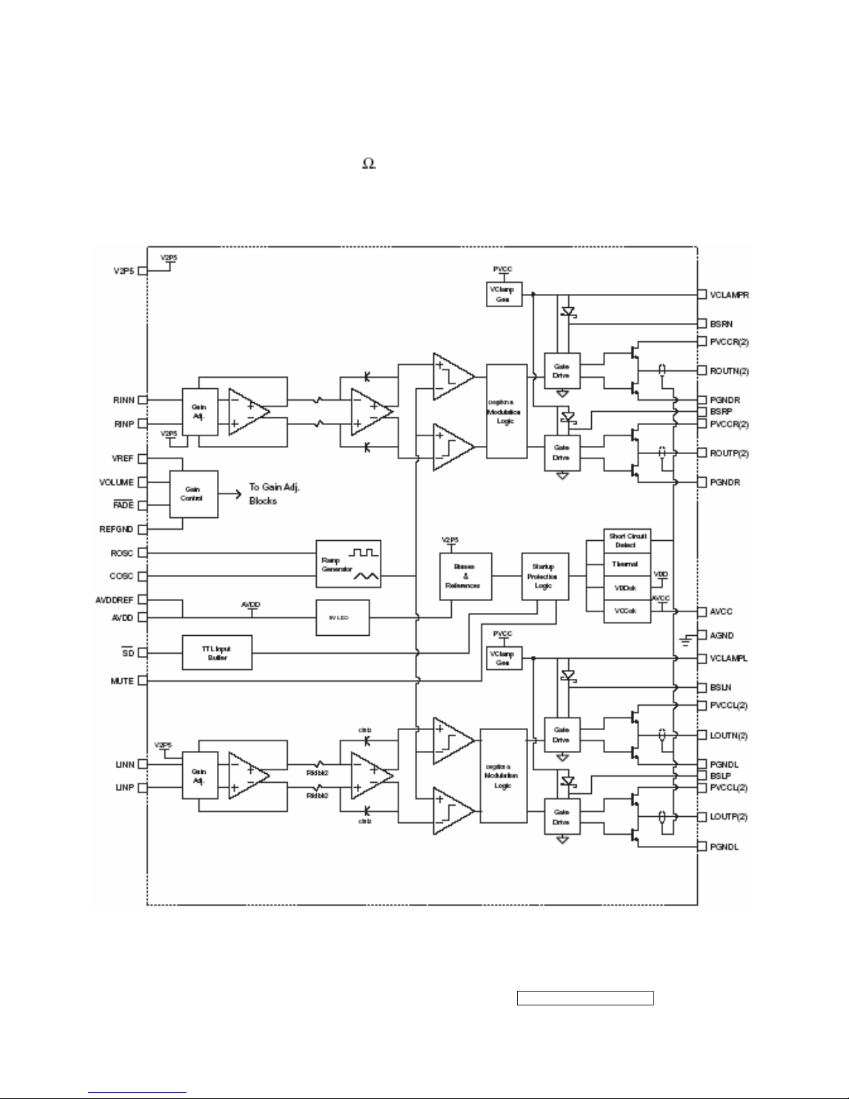
TPA3003D2 (U601): The TPA3003D2 is a audio amplifier IC,3-W efficient, driving
speakers as low as 8
, range of gain from -40dB to 36 dB. The function of
each pin and the inside circuit diagram are as follows:
Circuit Diagram
- 20 –
ViewSonic Corporation
Confidential - Do Not Copy VG720
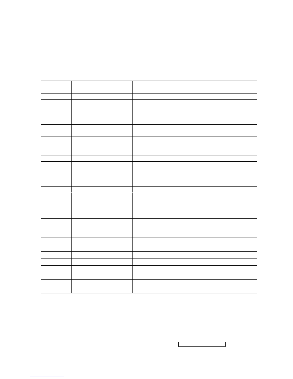
PIN Function
TERMINAL
NO. NAME
I/O DESCRIPTION
AGND 9,10,26 -
Analog ground for digital/analog cells in core
AVcc 33 -
High-voltage analog power supply (8.5V to 14V)
AVDD 29 O
5-V Regulated output
AVDDREF 7 O
5-V Reference output-provided for connection to adjacent VREF terminal.
BSLN 13 I/O
Bootstrap I/O for left channel, negative high-side FET
BSLP 24 I/O
Bootstrap I/O for left channel, positive high-side FET
BSRN 48 I/O
Bootstrap I/O for right channel, negative high-side FET
BSRP 37 I/O
Bootstrap I/O for right channel, positive high-side FET
COSC 28 I/O
I/O for charge/discharging currents onto capacitor for ramp generator triangle wave
biased at V2P5
FADE 30 I
Input for controlling volume ramp rate when cycling SD or during power-up. A logic
low on this pin places the amplifier in fade mode. A logic
high on this pin allows a quick transition to the desired volume setting.
LINN 6 I
Negative differential audio input for left channel
LINP 5 I
Positive differential audio input for left channel
LOUTN 16,17 O
Class-D 1/2-H-bridge negative output for left channel
LOUTP 20,21 O
Class-D 1/2-H-bridge positive output for left channel
MUTE 34 I
A logic high on this pin disables the outputs. A low on this pin enables the outputs.
NC 31,32,35 -
Not internally connected
PGNDL 18,19 -
Power ground for left channel H-bridge
PGNDR 42,43 -
Power ground for right channel H-bridge
PVVCCL 14,15 -
Power supply for left channel H-bridge(tied to pins 22 and 23 internally), not
connected to PVCCR or AVcc
PVVCCL 22,23 -
Power supply for left channel H-bridge(tied to pins 14 and 15 internally), not
connected to PVCCR or AVcc
PVCCR 38,39 -
Power supply for right channel H-bridge(tied to pins 46 and 47 internally), not
connected to PVCCL or AVcc
PVCCR 46,47 -
Power supply for right channel H-bridge(tied to pins 38 and 39 internally), not
connected to PVCCL or AVcc
REFGND 12 -
Ground for gain control circuitry. Connect to AGND. If using a DAC to control the
volume, connect the DAC ground to this terminal.
RINP 3 I
Positive differential audio input for right channel
RINN 2 I
Negative differential audio input for right channel
ROSC 27 I/O
Current setting resistor for ramp generator. Nominally equal to 1/8*Vcc
ROUTN 44,45 O
Class-D 1/2-H-bridge negative output for right channel
ROUTP 40,41 O
Class-D 1/2-H-bridge positive output for right channel
SD 1 I
Shutdown signal for IC (low=shutdown, high=operational). TTL logic levels with
compliance to Vcc.
VCLAMPL 25 -
Internally generated voltage supply for left channel bootstrap capacitors.
VCLAMPR 36 -
Internally generated voltage supply for right channel bootstrap capacitors.
VOLUME 11 I
DC voltage that sets the gain of the amplifier.
VREF 8 I
Analog reference for gain control section.
V2P5 4 O
2.5-V Reference for analog cells, as well as reference for unused audio input when
using single-ended inputs.
- 21 –
ViewSonic Corporation
Confidential - Do Not Copy VG720
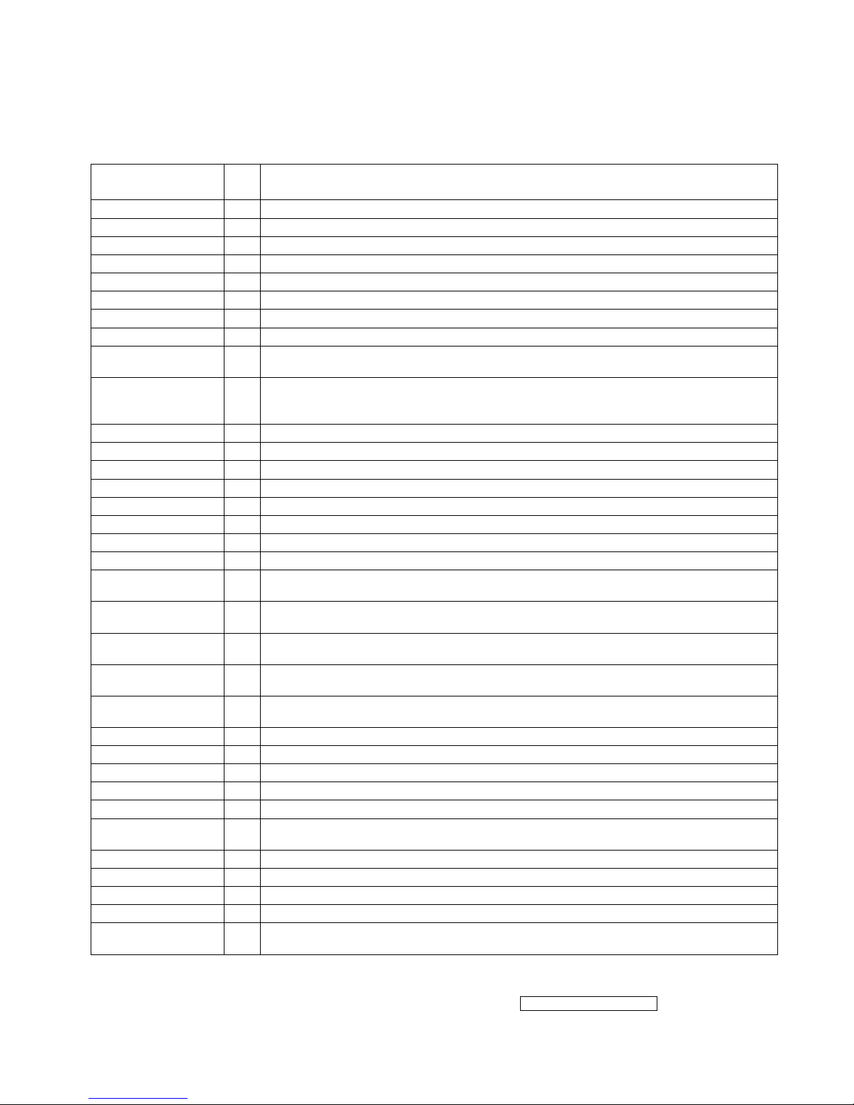
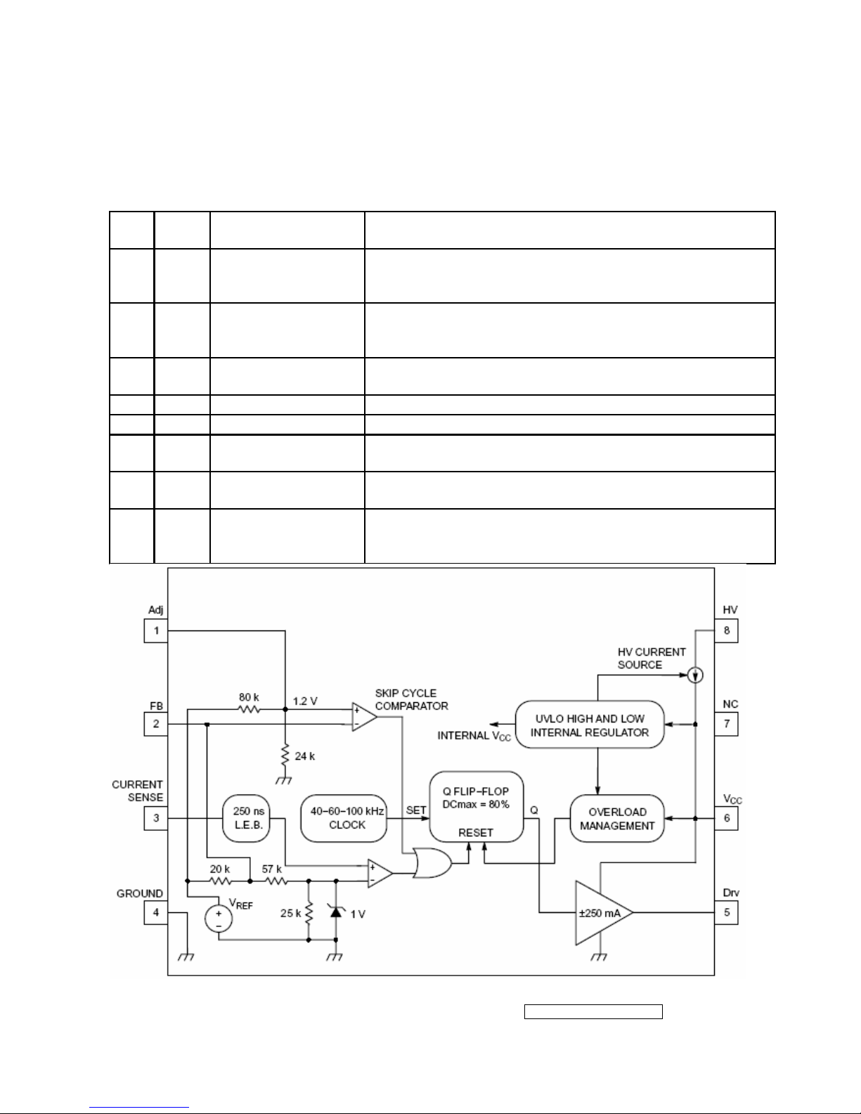
NCP1203D60R2G (IC901): PWM control, high-voltage startup current. The circuit unit
has functions such as over-current protection, over-voltage protection, output
short-circuit protection and etc. The function of each pin and the inside circuit diagram
are as follows:
Pin
No.
Pin
Name
Function Pin Description
1 Adj
Adjust the skipping
peak current
This pin lets you adjust the level at which the cycle
skipping process takes place. Shorting this pin to ground,
permanently disables the skip cycle feature.
2 FB
Sets the peak
current setpoint
By connecting an optocoupler to this pin, the peak current
setpoint is adjusted accordingly to the output power
demand. Skip cycle occurs when FB falls below Vpin1.
3 CS Current sense input
This pin senses the primary current and routes it to the
internal comparator via an L.E.B.
4 GND The IC ground −
5 Drv Driving pulses The driver’s output to an external MOSFET.
6 VCC Supplies the IC
This pin is connected to an external bulk capacitor of
typically 22 F.
7 NC −
This unconnected pin ensures adequate creepage
distance.
8 HV
Ensure a clean and
lossless startup
sequence
Connected to the high−voltage rail, this pin injects a
constant current into the VCC capacitor during the startup
sequence.
- 22 –
ViewSonic Corporation
Confidential - Do Not Copy VG720
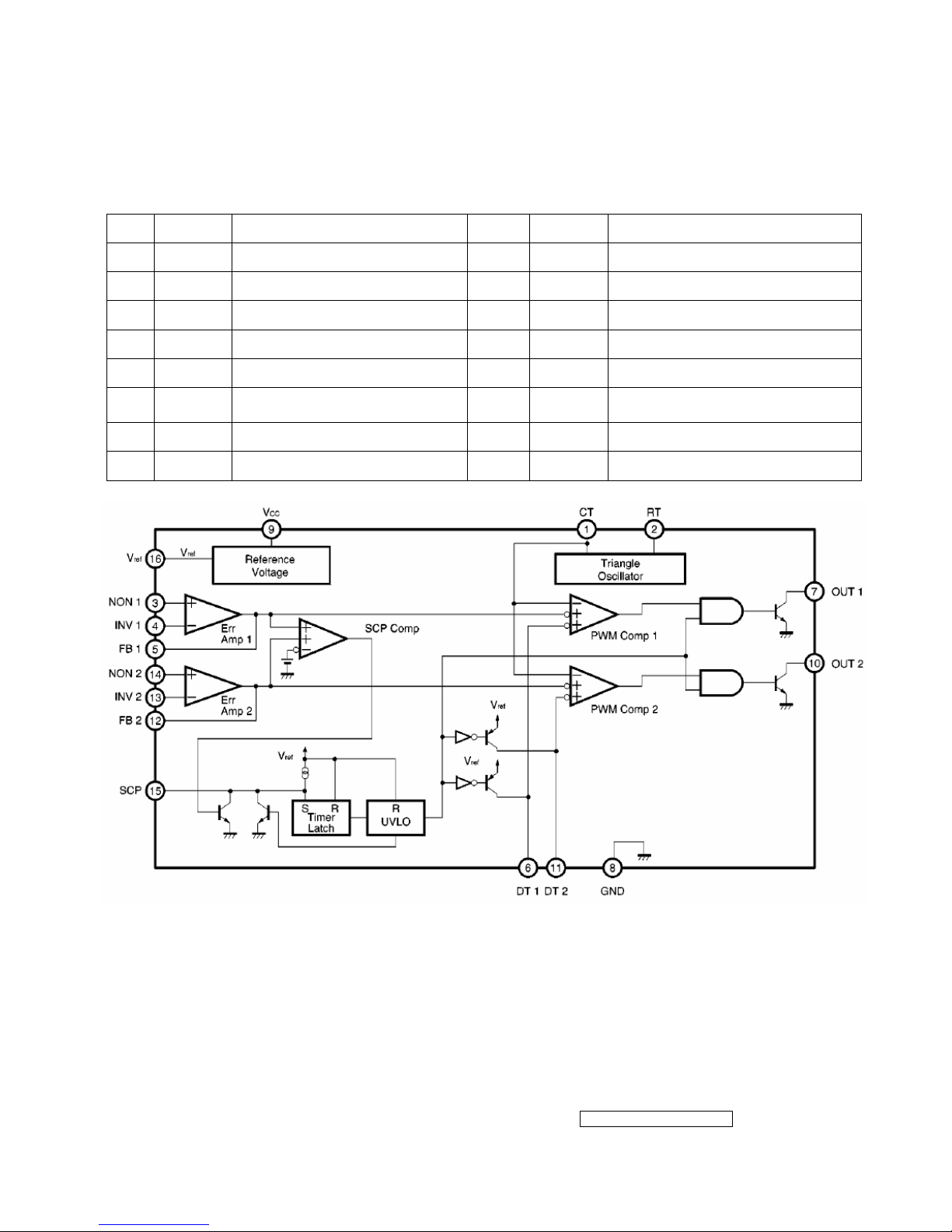
TL1451 (IC201): PWM control, voltage range for working: 3.6~35V, Has such functions
as short-voltage protection, Over-voltage protection, over-current protection and
etc. The function of each pin and the circuit diagram inside are as follows:
Pin Symbol Description Pin Symbol Description
1 CT External timing capacitor 9 VCC Power supply
2 RT External timing resistor 10 2OUT Output 2
3 1IN+ Positive input for error amplifier 1 11 2DTC Output 2 dead time/soft start setting
4 1IN- Positive input for error amplifier 2 12 2FBK Error amplifier 2 output
5 1FBK Error amplifier 1 output 13 2IN+ Positive input for error amplifier
6 1DTC
Output 1 dead time/soft start
setting
14 2IN- Positive input for error amplifier
7 1OUT Output 1 15 SCP Timing latch setting
8 GND Ground 16 REF Reference voltage output (2.5v)

- 23 –
ViewSonic Corporation
Confidential - Do Not Copy VG720
5. Adjustment Procedure
5.1 ADJUSTMENT CONDITIONS AND PRECAUTIONS
1. Approximately 30 minutes should be allowed for warm up before proceeding.
2. Adjustments should be undertaken only on those necessary elements since most of them
have been carefully preset at the factory.
3. ESD protection is needed before adjustment.
5.2 MAIN ADJUSTMENTS
NO. FUNCTIONS DESIGNATION
1. White Balance Function Key
2. Geometry Function Key
5.3 ALIGNMENT PROCEDURES
Approximately 30 minutes should be allowed for warm up before proceeding
White-Balance adjustment.
1. Adjust of White Balance
1.)How to do the Chroma-7120 MEM .Channel setting
A、Reference to chroma 7120 user guide
B、Use “ SC” key and “ NEXT” key to modify xyY value and use “ID” key to modify the
TEXT description Following is the procedure to do white-balance adjust
2.)Setting the color temp. You want
A、MEM.CHANNEL9 ( 9300 color):
9300 color temp. parameter is Wx = 0.283 ±0.03;Wy = 0.298 ±0.03;
Y = 250 ±20 cd/m
2 ,
B、MEM.CHANNEL10 ( 6500 color):
6500 color temp. parameter is Wx = 0.313±0.03;Wy = 0.329 ±0.03;
Y = 260 ±20 cd/m
2,
C、MEM.CHANNEL 11 ( 5400 color):
5400 color temp. parameter is Wx = 0.335±0.03;Wy = 0.350 ±0.03;
Y = 250 ±20 cd/m
2,
D、MEM.CHANNEL10 ( SRGB color):
6500 color temp. parameter is Wx = 0.313±0.03;Wy = 0.329 ±0.03;
Y = 220 ±20 cd/m
2,
- 24 –
ViewSonic Corporation
Confidential - Do Not Copy VG720
3.)Into factory mode of VG720
A、First Power off, then press Switch 2 button along with press Power button will activate
the factory mode, then MCU will do AUTO LEVEL automatically. Meanwhile press
MENU the OSD screen will located at LEFT TOP OF PANEL.
4.)Bias adjustment :
Set the Contrast
to 70
Adjust the Brightness
to 100.
5.)Gain adjustment :
Move cursor to “-F-” and press MENU key
A、Adjust 9300 color-temperature
(1)、Switch the Chroma-7120 to RGB-Mode (with press “MODE” button )
(2)、Switch the MEM. channel to Channel 9 ( with up or down arrow on chroma 7120 )
(3)、The LCD-indicator on chroma 7120 will show x = 0.283 ±0.03, y =0.298 ±0.03,
Y = 250 ±20 cd/m
2
(4)、Adjust the RED of color1 on factory window until chroma 7120 indicator reached
the value R=100
(5)、Adjust the GREEN of color1 on factory window until chroma 7120 indicator reached
the value G=100
(6)、Adjust the BLUE of color1 on factory window until chroma 7120 indicator reached
the value B=100
(7)、Repeat above procedure ( item 4,5,6) until chroma 7120 RGB value meet the
tolerance =100±5
B、Adjust 6500 color-temperature
(1)、Switch the chroma-7120 to RGB-Mode (with press “MODE” button )
(2)、Switch the MEM .channel to Channel 10( with up or down arrow on chroma 7120 )
(3)、The LCD-indicator on chroma 7120 will show x = 0.313 ±0.03, y = 0.329 ±0.03, Y =
260 ±20 cd/m
2
(4)、Adjust the RED of color3 on factory window until chroma 7120 indicator reached
the value R=100
(5)、Adjust the GREEN of color3 on factory window until chroma 7120 indicator reached
the value G=100
(6)、Adjust the BLUE of color3 on factory window until chroma 7120 indicator reached
the value B=100
(7)、Repeat above procedure ( item 4,5,6) until chroma 7120 RGB value meet the
tolerance =100±5

- 25 –
ViewSonic Corporation
Confidential - Do Not Copy VG720
C、Adjust 5400 color-temperature
(1) Switch the chroma-7120 to RGB-Mode (with press “MODE” button )
(2)、Switch the MEM .channel to Channel 11( with up or down arrow on chroma 7120 )
(3)、The LCD-indicator on chroma 7120 will show x = 0.335 ±0.03, y = 0.350 ±0.03, Y =
250 ±20 cd/m
2
(4)、Adjust the RED of color3 on factory window until chroma 7120 indicator reached the
value R=100
(5)、Adjust the GREEN of color3 on factory window until chroma 7120 indicator reached
the value G=100
(6)、Adjust the BLUE of color3 on factory window until chroma 7120 indicator reached
the value B=100
(7)、Repeat above procedure ( item 4,5,6) until chroma 7120 RGB value meet the
tolerance =100±5
D、Adjust SRGB color-temperature
(1)、Switch the chroma-7120 to RGB-Mode (with press “MODE” button )
(2)、Switch the MEM .channel to Channel 10( with up or down arrow on chroma 7120 )
(3)、The LCD-indicator on chroma 7120 will show x = 0.313 ±0.03, y = 0.329 ±0.03, Y =
220 ±20 cd/m
2
(4)、Adjust the RED of color3 on factory window until chroma 7120 indicator reached
the value R=100
(5)、Adjust the GREEN of color3 on factory window until chroma 7120 indicator reached
the value G=100
(6)、Adjust the BLUE of color3 on factory window until chroma 7120 indicator reached
the value B=100
(7)、Repeat above procedure ( item 4,5,6) until chroma 7120 RGB value meet the
tolerance =100±5
E、Press reset key and Turn the Power-button “off to on” to quit from factory mode.
2. Geometry
1).Set cross-hatch pattern and preset timing as timing table listed.
2).Change to each mode in turn and wait for the monitor finish auto-alignment and save
press before change to next mode.
3).Until all of modes are adjusted,exit OSD menu and press POWER OFF to exit factory
mode.
- 26 –
ViewSonic Corporation
Confidential - Do Not Copy VG720
5.4 Factory Defaults
Item Defaults Item Defaults
Contrast 70% Sharpness 33%
Brightness 100% OSD H. Position 50%
Volume 50% OSD V. Position 50%
Balance 50% OSD Time Out 15 Sec
Bass 50% OSD Background On
Treble 50% OSD PIVOT Off
Color Temperature 6500K Resolution Notice Enabled
720x400/640x400 720x400
5.5 Function Test
1 Product: 17” LCD Monitor
2 Test Equipment: Color Video Signal & Pattern (or PC with SXGA resolution and a
sound card)
3 Test Condition: Before function test and alignment, each LCD Monitor should be
warmed up for at least 30 minutes with the following conditions:
(a)In room temperature,
(b) With full-white screen, RGB, and Black
(c) With cycled display modes,
640*480 (H=43.27kHz, V=85Hz)
800*600 (H=53.7kHz, V=85Hz)
1024*768 (H=68.67kHz, V=85Hz)
1280*1024 (H=79.97kHz, V=75Hz)
4 Test Display Modes & Pattern
Compatible Modes
Analog Digital
640 x 350 @ 70Hz, 31.5kHz
640 x 400 @ 70Hz, 31.5kHz
640 x 480 @ 60Hz, 31.5kHz
640 x 480 @ 67Hz, 35.0kHz
640 x 480 @ 72Hz, 37.9kHz
640 x 480 @ 75Hz, 37.5kHz
720 x 400 @ 70Hz, 31.5kHz
800 x 600 @ 56Hz, 35.1kHz
800 x 600 @ 60Hz, 37.9kHz
800 x 600 @ 75Hz, 46.9kHz
800 x 600 @ 72Hz, 48.1kHz
832 x 624 @ 75Hz, 49.7kHz
1024 x 768 @ 60Hz, 48.4kHz
 Loading...