

ViewSonic VG2021m-1, VS11234 Service Manual
ViewSonic VG2021m-1
Model No. VS11234
20” Color TFT LCD Display
(VG2021m-1_SM Rev. 1a Apr. 2006)
ViewSonic 381 Brea Canyon Road, Walnut, California 91789 USA – (800) 888-8583
Service Manual
Display
ViewSonic Corporation
Copyright
Copyright © 2006 by ViewSonic Corporation. All rights reserved. No part of this publication
may be reproduced, transmitted, transcribed, stored in a retrieval system, or translated into any
language or computer language, in any form or by any means, electronic, mechanical, magnetic,
optical, chemical, manual or otherwise, without the prior written permission of ViewSonic
Corporation.
Disclaimer
ViewSonic makes no representations or warranties, either expressed or implied, with respect to
the contents hereof and specifically disclaims any warranty of merchantability or fitness for any
particular purpose. Further, ViewSonic reserves the right to revise this publication and to make
changes from time to time in the contents hereof without obligation of ViewSonic to notify any
person of such revision or changes.
Trademarks
Optiquest is a registered trademark of ViewSonic Corporation.
ViewSonic is a registered trademark of ViewSonic Corporation.
All other trademarks used within this document are the property of their respective owners.
Revision History
Revision SM Editing Date ECR Number Description of Changes Editor
1a 04/03/2006 Initial Release Jamie Chang
VG2021m-1 Confidential - Do Not Copy
ViewSonic Corporation
TABLE OF CONTENTS
1. Precautions and Safety Notices 1
2. Specification 4
3. Front Panel Function Control Description 12
4. Circuit Description 17
5. Adjustment Procedure 18
6. Troubleshooting Flow Chart 51
7. Recommended Spare Parts List 59
8. Exploded Diagram and Exploded Parts List 63
9. Block Diagram 67
10. Schematic Diagrams 68
11. PCB Layout Diagrams 84
VG2021m-1 Confidential - Do Not Copy

ViewSonic Corporation
1
1. Precautions and Safety Notices
1. Appropriate Operation
(1) Turn off the product before cleaning.
(2) Use only a dry soft cloth when cleaning the LCD panel surface.
(3) Use a soft cloth soaked with mild detergent to clean the display housing.
(4) Use only a high quality, safety approved AC/DC power cord.
(5) Disconnect the power plug from the AC outlet if the product will not be used for a long period of time.
(6) If smoke, abnormal noise, or strange odor is present, immediately switch the LCD display off.
(7) Do not touch the LCD panel surface with sharp or hard objects.
(8) Do not place heavy objects on the LCD display, video cable, or power cord.
(9) Do not use abrasive cleaners, waxes or solvents for your cleaning.
(10) Do not operate the product under the following conditions:
- Extremely hot, cold or humid environment.
- Areas containing excessive dust and dirt.
- Near any appliance generating a strong magnetic field.
- In direct sunlight.
2. Caution
No modification of any circuit should be attempted. Service work should only be performed after you are thoroughly
familiar with all of the following safety checks and servicing guidelines.
3. Safety Check
Care should be taken while servicing this LCD display. Because of the high voltage used in the inverter circuit, the
voltage is exposed in such areas as the associated transformer circuits.
4. LCD Module Handling Precautions
4.1 Handling Precautions
(1) Since front polarizer is easily damaged, pay attention not to scratch it.
(2) Be sure to turn off power supply when connecting or disconnecting input connector.
(3) Wipe off water drops immediately. Long contact with water may cause discoloration or spots.
(4) When the panel surface is soiled, wipe it with absorbent cotton or other soft cloth.
(5) Since the panel is made of glass, it may break or crack if dropped or bumped on hard surface.
(6) Since CMOS LSI is used in this module, take care of static electricity and ensure human earth when handling.
(7) Do not open or modify the Module Assembly.
(8) Do not press the reflector sheet at the back of the module in any direction.
VG2021m-1 Confidential - Do Not Copy

ViewSonic Corporation
2
(9) In the event that a Module must be put back into the packing container slot after it was taken out of the container, do
not press the center of the CCFL Reflector edge. Instead, press at the far ends of the CFL Reflector edge softly.
Otherwise the TFT Module may be damaged.
(10) At the insertion or removal of the Signal Interface Connector, be sure not to rotate or tilt the Interface Connector of the
TFT Module.
(11) After installation of the TFT Module into an enclosure (LCD monitor housing, for example), do not twist or bend the
TFT Module even momentarily. When designing the enclosure, it should be taken into consideration that no
bending/twisting forces may be applied to the TFT Module from outside. Otherwise the TFT Module may be damaged.
(12) The cold cathode fluorescent lamp in the LCD contains a small amount of mercury. Please follow local ordinances or
regulations for disposal.
(13) The LCD module contains a small amount of materials having no flammability grade. The LCD module should be
supplied with power that complies with the requirements of Limited Power Source (IEC60950 or UL1950), or an
exemption should be applied for.
(14) The LCD module is designed so that the CCFL in it is supplied by a Limited Current Circuit (IEC60950 or UL1950).
Do not connect the CCFL to a Hazardous Voltage Circuit
VG2021m-1 Confidential - Do Not Copy
ViewSonic Corporation
3
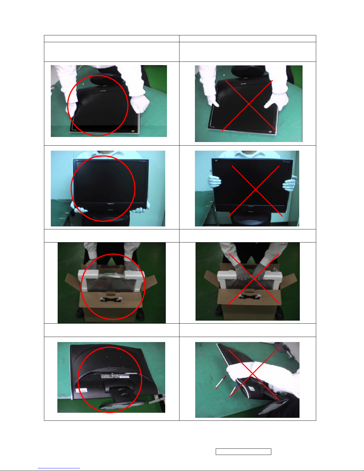
Correct methods : Incorrect Methods :
Only touch the metal-frame of the panel or the front
cover of the monitor.
Do not touch the surface of the polarizer .
Surface of the panel is pressed by fingers & this may
cause “ MURA “
Take out the monitor with cushion Take out the monitor by grasping the LCD panel.
That may cause “ MURA“.
Place the monitor on a clean & soft foam pad . Place the monitor on foreign objects .
That could scratch the surface of panel
VG2021m-1 Confidential - Do Not Copy
ViewSonic Corporation
4
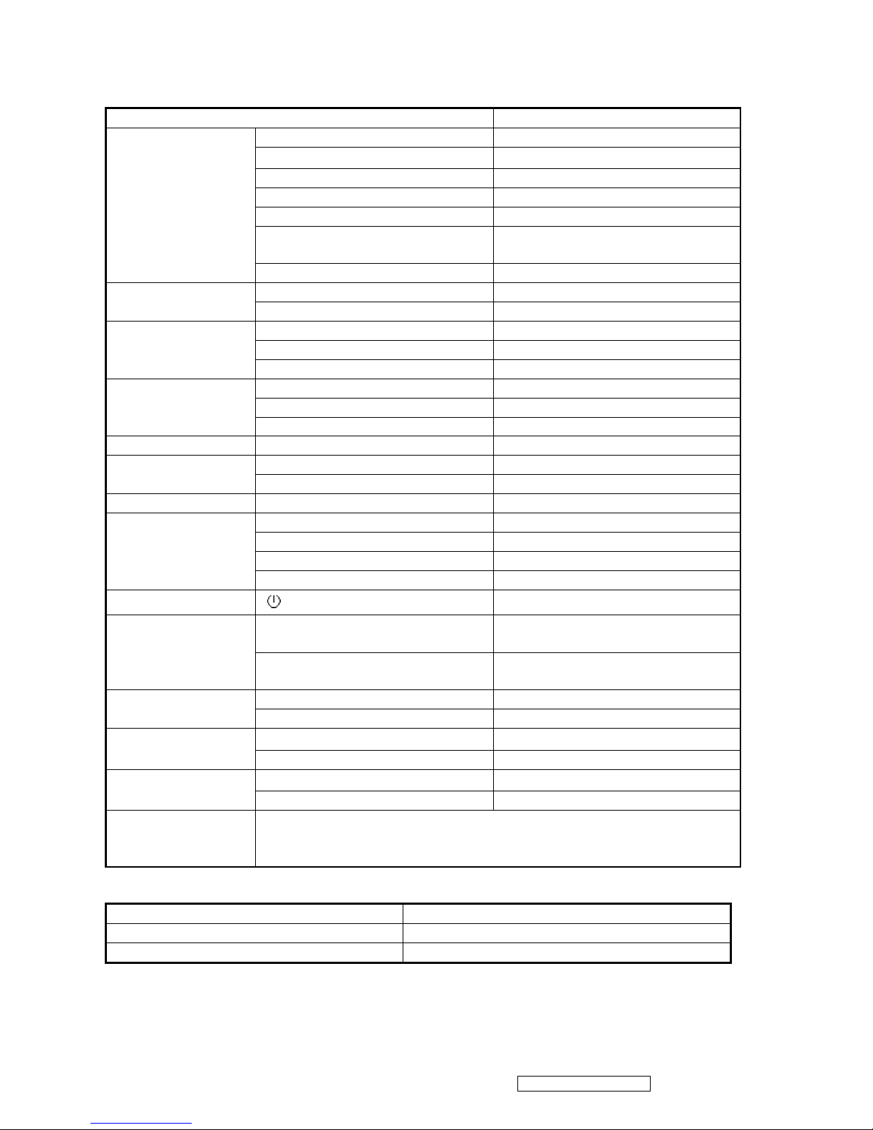
2. Specification
INTRODUCTION
FEATURES VG2021M-1
Size 20.1 “
Luminance (Typ)
300 cd/㎡
Contrast Ratio (Typ) 500:1
Colors 16.2 M colors
Response Time (Typ) 8 ms
Viewing Angle (H/V) 150 / 130 @CR>=10
170/ 150 @CR>= 5
TFTLCD PANEL
Recommend resolution 1400 X 1050 @60Hz
Analog (75ohms, 0.7/1.0 Vp-p)
Yes
Input Signal
Digital Yes
Separate Sync Yes
Composite Sync No
Sync Compatibility
Sync on Green No
PC Yes
Power Mac Yes
Compatibility
TV Box (NextVision 6) Yes
Power Voltage AC 100-240V, 50/60Hz Yes
On Mode(Max / Typ) 45 W / 30 W Power
Consumption
Active Off Mode (Max) 1 W
Audio W 2.5W
Tilt -5 ° ~ 20 °
Swivel ( -xx ° - xx °) No
Pivot ( XX ° - XX °) No
Ergonomics
Height Adjust ( XX-XX mm) No
OSD Control [ ] [ 1 ] [ 2 ] [?] [?] [X X] Yes
Physical (W x H x D) 459 x 465 x 205(mm ),
18.1 x18.3x8.1(in)
Dimension
Package (W x H x D) 490x510x160 (mm)
19.3 x 20.1 x6.3 (in)
Physical (lbs / Kg) 13.7 lbs (6.2 kgs )
Weight
Package (lbs / Kg) 16.9 lbs( 7.7 kgs )
Temperature (℉/℃) 41℉-95 ℉ / 5℃-35℃
Operating
Condition
Humidity (%) 20 % - 80 %
Temperature (℉/℃) -4℉-131℉ / -20℃-55 ℃
Storage Condition
Humidity (%) 20 % - 85 %
Regulation
CB / TCO03/ UL/cUL / FCC-B / ICES 003 / Argentina-TUV/S /
NOM / EPA Energy Star / TUV/Ergo / ISO13406-2 / TUV/GS / CE /
GOST-R / SASO / BSMI / PSB / C-Tick / MIC / CCC
GENERAL specification
Test Resolution & Frequency “1400 X 1050” @ 60Hz
Test Image Size Full Size
Contrast and Brightness Controls Factory Default
VG2021m-1 Confidential - Do Not Copy
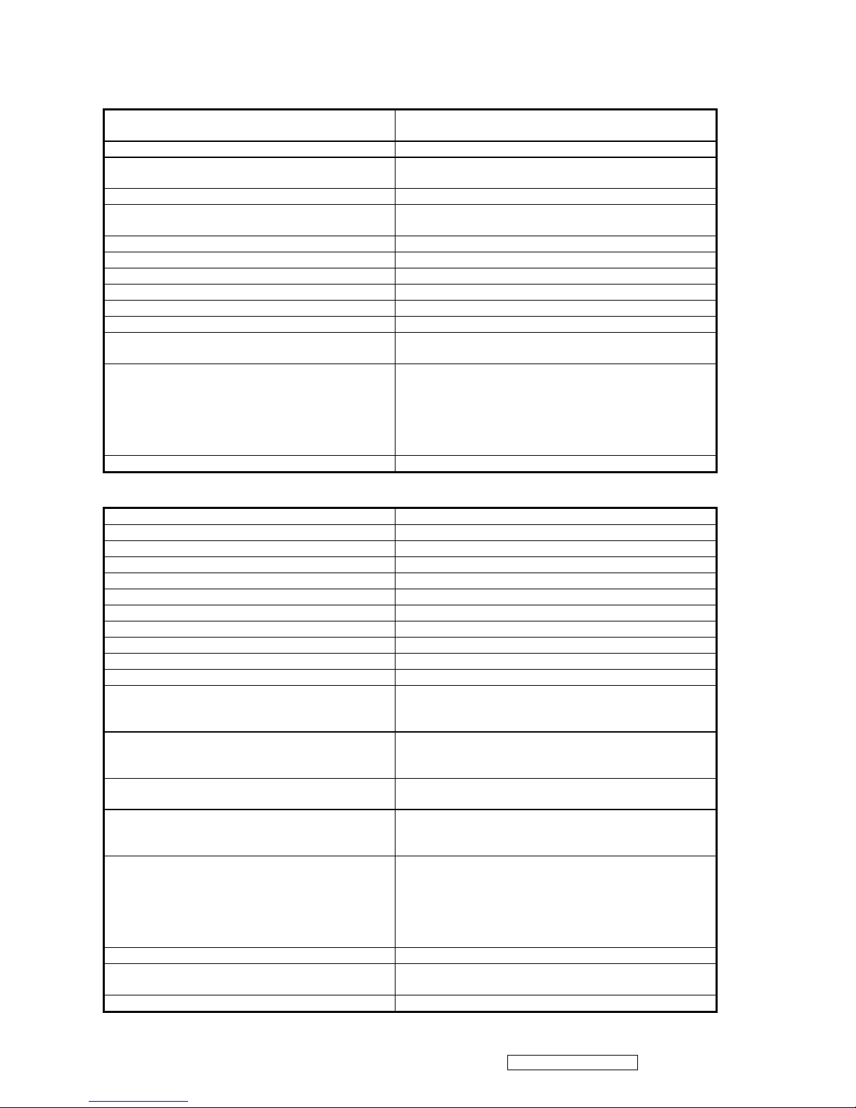
VIDEO INTERFACE
Input Connector(refer the appendix A) Analog : D-sub 15 ,
Digital: DVI-D
Default Input Connector Defaults to the first detected input
Video Cable Strain Relief
Equal to twice the weight of the monitor for five
minutes
Video Cable Connector DB-15 Pin out Compliant DDC 2B
Video Signals
1. Video RGB (Analog): Separate
2. DVI (Digital)
Video Impedance 75 Ohms (Analog), 100 Ohms (Digital)
Maximum PC Video Signal 950 mV with no damage to monitor
Maximum Mac Video Signal 1250 mV with no damage to monitor
Sync Signals TTL
DDC 1/2B Compliant with Revision 1.3
Sync Compatibility Separate Sync
Video Compatibility
Shall be compatible with all PC type computers,
Macintosh computers, and after market video cards
Resolution Compatibility
640 x 350, 640 x 480, 720 x 400 * (640 x 400*) 800 x
600, 832 x 624, 1024 x 768, 1152x864, 1280X960,
1280x1024, 1400x1050
* The image vertical size might not be full screen.
But the image vertical position should be at the
center
Exclusions Not compatible with interlaced video
POWER SUPPLY
Internal Power Supply Part Number: DAC-12M033 AF(DELTA)
Input Voltage Range 90 TO 264 VAC
Input Frequency Range 47.5 TO 63 HERTZ
Short Circuit Protection Output can be shorted without damage
Over Current Protection N/A
Leakage Current 3.5mA (Max) at 254VAC / 60Hz
EFFICIENCY 80 % typical at 115VAC Full Load
Fuse Internal and not user replaceable
Power Dissipation 50 Watts (typ)
Max Input AC Current 1.0Arms @ 90VAC, 0.8 Arms @180VAC
INRUSH CURRENT (COLD START) 30 A @ 120VAC, 60 A(max) @220VAC
Power Supply Cold Start
Shall start and function properly when under full load,
with all combinations of input voltage, input
frequency, and operating temperature
Power Supply Transient Immunity
Shall be able to withstand an ANSI/IEEE
C62.41-1980 6000V 200 ampere ring wave transient
test with no damage
Power Supply Line Surge Immunity
Shall be able to withstand 1.5 times nominal line
voltage for one cycle with no damage
Power Supply Missing Cycle Immunity
Shall be able to function properly, without reset or
visible screen artifacts, when ½ cycle of AC power is
randomly missing at nominal input
Power Supply Acoustics
The power supply shall not produce audible noise
that would be detectable by the user. Audible shall
defined to be in compliance with ISO 7779 (DIN
EN27779:1991) Noise measurements of machines
acoustics. Power Switch noise shall not be
considered
Power Saving Operation(Method) VESA DPMS Signaling
Power Consumption
ON Mode < 40 W (max) / 30 W (typ)
ACTIVE OFF < 1W
Recovery Time ON MODE = N/A, ACTIVE OFF < 3 SEC
ViewSonic Corporation
5
VG2021m-1 Confidential - Do Not Copy
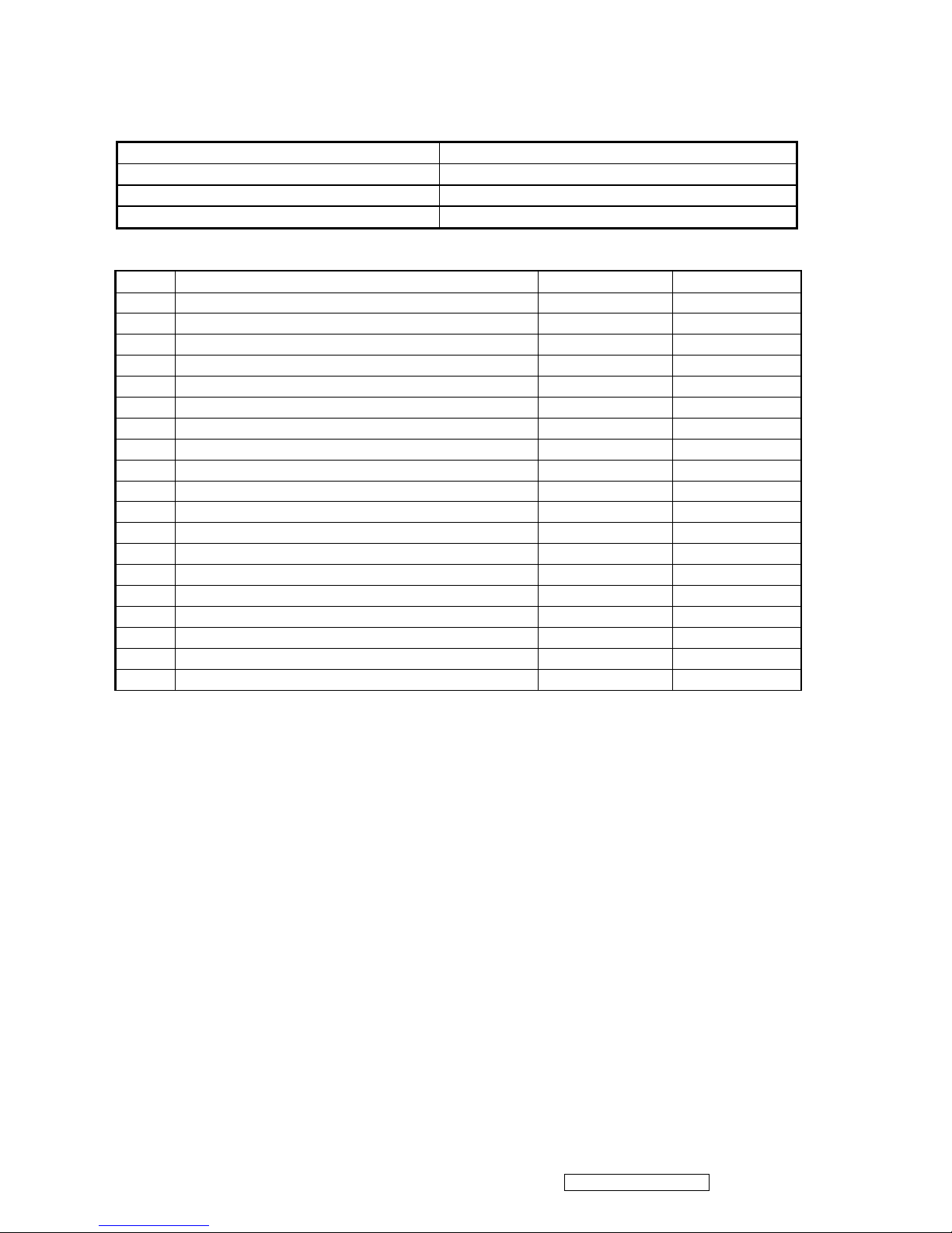
ELECTRICAL REQUIREMENT
Horizontal / Vertical Frequency
Horizontal Frequency 30 – 82 KHZ
Vertical Refresh Rate 56– 76 HZ.
Maximum Pixel Clock 156 MHz
Sync Polarity Independent of sync polarity.
Timing Table
Item
Timing Analog Digital
1.
640 x 400 @ 70Hz, 31.5kHz Yes Yes
2.
640 x 480 @ 60Hz, 31.5kHz Yes Yes
3.
640 x 480 @ 67Hz, 35.0kHz Yes Yes
4.
640 x 480 @ 72Hz, 37.9kHz Yes Yes
5.
640 x 480 @ 75Hz, 37.5kHz Yes Yes
6.
720 x 400 @ 70Hz, 31.5kHz Yes Yes
7.
800 x 600 @ 56Hz, 35.1kHz Yes Yes
8.
800 x 600 @ 60Hz, 37.9kHz Yes Yes
9.
800 x 600 @ 75Hz, 46.9kHz Yes Yes
10. 800 x 600 @ 72Hz, 48.1kHz Yes Yes
11. 832 x 624 @ 75Hz, 49.7kHz Yes Yes
12. 1024 x 768 @ 60Hz, 48.4kHz Yes Yes
13. 1024 x 768 @ 70Hz, 56.5kHz Yes Yes
14. 1152X 864 @75Hz, 67.5kHz Yes Yes
15. 1152X 870 @75Hz, 70.8kHz Yes Yes
16. 1024 x 768 @ 75Hz, 60.0kHz Yes Yes
17. 1280 x 1024 @ 60Hz, 63.4kHz Yes Yes
18. 1280 x 1024 @ 75Hz, 79.97kHz Yes Yes
19. 1400x 1050 @ 60Hz, 65.3kHz Yes Yes
Primary Presets
“1400 x 1050” @ 60Hz
User Presets
Number of User Presets (recognized timings) Available: 10 presets total in FIFO configuration
Changing Modes
l Maximum Mode Change Blank Time for image stability : 3 seconds (Max), excluding
“Auto Adjust” time
l Under DOS mode (640 x 350, 720 x 400 & 640 x 400), it should recall factory setting
when execute “Auto Adjust”
l The monitor needs to do “Auto Adjust” the first time a new mode is detected
l (see section “0-Touch™ Function Actions”)
l While running Change Mode, Auto Adjust or Memory Recall, the image shall blank
ViewSonic Corporation
6
VG2021m-1 Confidential - Do Not Copy
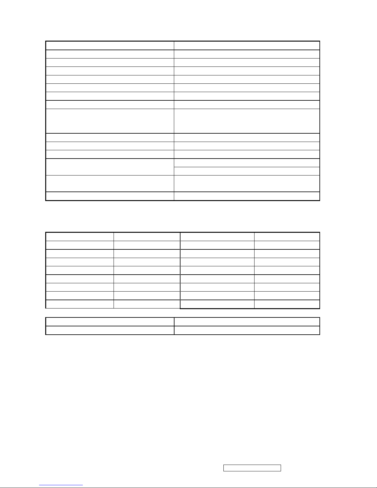
Panel Characteristics:
1st Source Panel A201P1
Type “TN Technology”
Active Size 408.24 (H) x 306.18(V)
Pixel Arrangement RGB Vertical Stripe
Pixel Pitch 0.2916 mm
GLASS TREATMENT Anti Glare (Hard coating 3H)
# OF BACKLIGHTS 4 CCFL edge-light (2 top / 2 bottom)
BACKLIGHT LIFE 50,000 Hours (Min)
Luminance – Condition:
CT = 6500K, Contrast = Max,
Brightness = Max
300 cd/m2 (Typ after 30 minute warm up)
200 cd/m2 (Min after 30 minute warm up)
Brightness Uniformity 77%(typ); 67% (min)
Contrast Ratio 500:1 (Typ), 350:1 (Min)
Color Depth 16.2 million colors (6 bit +FRC panel)
150/130 (typ), 130/110(min) @ CR>10, Viewing Angle (Horizontal/ vertical)
170/150 (typ), 150/130 (min) @ CR>5
Response Time
10%-90% @ Ta=25°C
8 ms (Tr= 2 ms, Tf = 6 ms) (Typ)
18 ms (Tr= 7 ms, Tf = 11 ms) (Max)
Panel Defects Please see Panel Quality Specifications.
IMAGE PERFORMANCE
Factory Defaults
Item Defaults Item Defaults
Contrast 70% Sharpness 100%
Brightness 100% OSD H. Position 50%
Volume 50% OSD V. Position 50%
Balance N/A OSD Time Out 15 Sec
Bass N/A OSD Background On
Treble N/A OSD PIVOT N/A
Color Temperature 6500K Resolution Notice on
720x400/640x400 720x400
Display Size
Horizontal Display Size, Primary Preset Full Screen
Vertical Display Size, Primary Preset Full Screen
ViewSonic Corporation
7
VG2021m-1 Confidential - Do Not Copy
ViewSonic Corporation
8
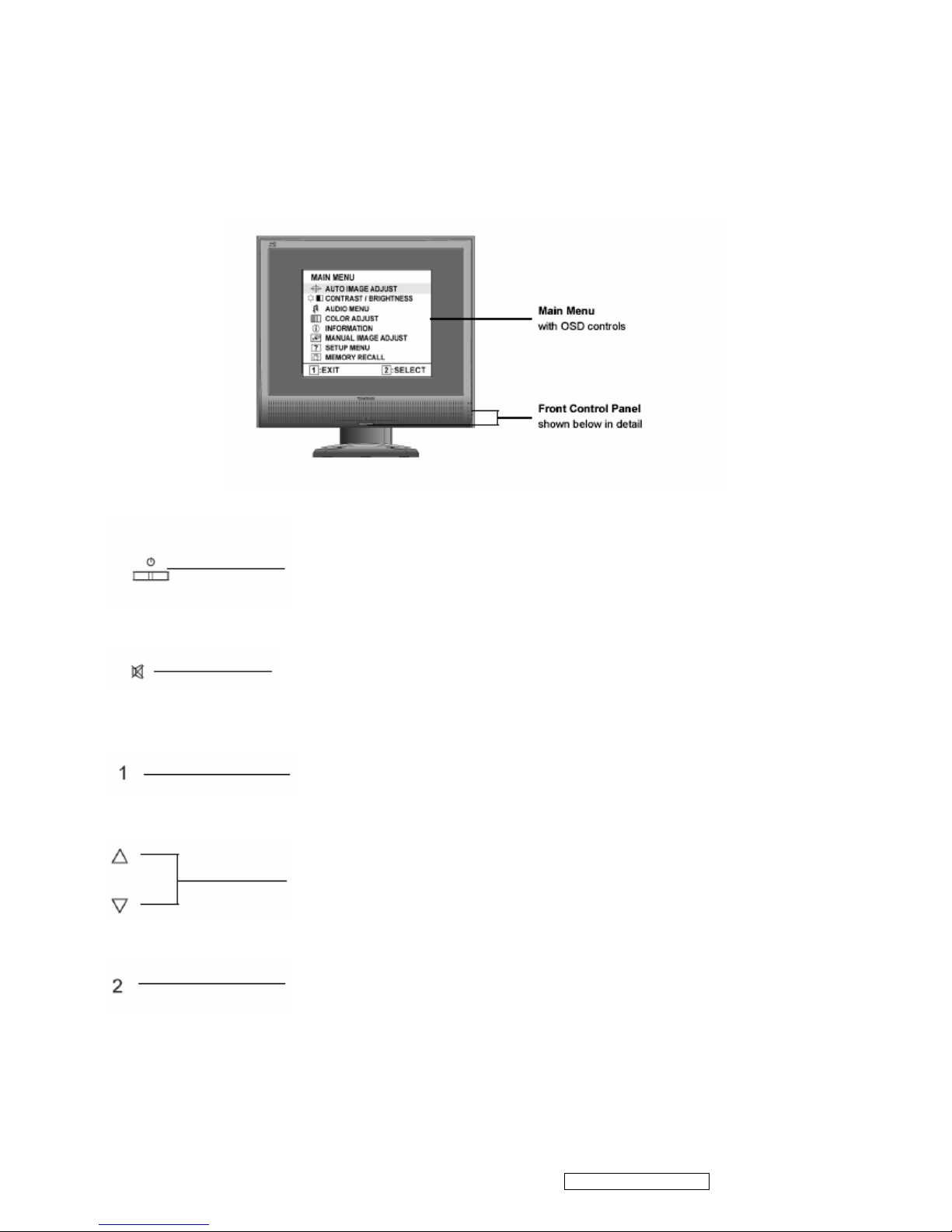
3. Front Panel Function Control Description
Adjusting the Screen Image
Use the buttons on the front control panel to display and adjust the OSD controls which display
on the screen.
Power light
Blue = ON
Orange = Power Saving
Standby Power On/Off
Audio Mute button turns the sound off
Displays the Main Menu or exits the control screen
and saves adjustments.
Scrolls through menu options and adjusts the displayed control.
Also a shortcut to display the Contrast adjustment control screen.
Displays the control screen for the highlighted control.
Also toggles between two controls on some screens.
VG2021m-1 Confidential - Do Not Copy
ViewSonic Corporation
9
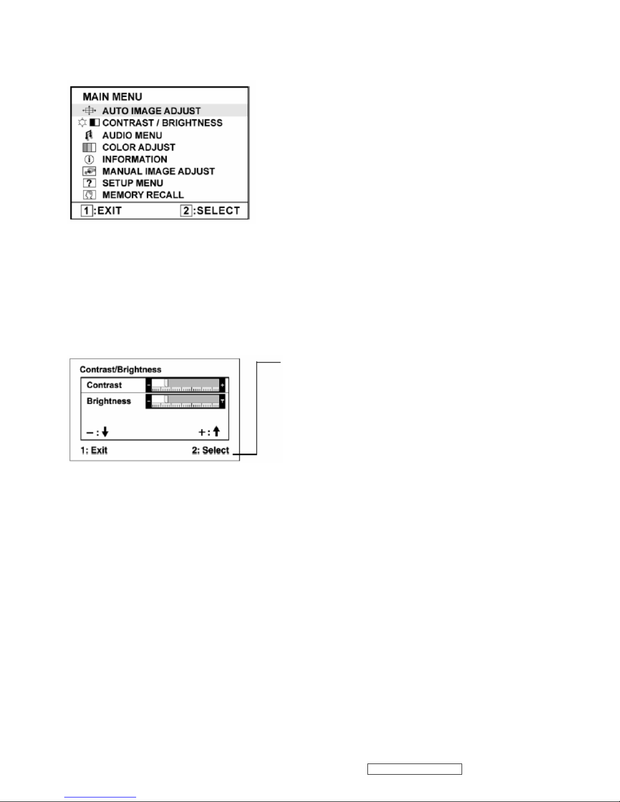
Do the following to adjust the screen image:
1. To display the Main Menu, press button [1].
NOTE: All On View menus and adjustment screens disappear automatically after about 15 seconds. This is adjustable through
the OSD timeout setting in the setup menu.
2. To select a control you want to adjust, press p or qto scroll up or down the Main Menu.
3. After the control is selected, press button [2]. A control screen like the one shown below
appears.
The command line at the bottom of the control screen
tells what to do next from this screen. You can toggle
between control screens, adjust the selected option, or
exit the screen.
4. To adjust the setting, press the up p or down q buttons.
5.To save the adjustments and exit the menu, press button [1] twice.
The following tips may help you optimize your display:
• Adjust the computer's graphics card so that it outputs a 1400 x 1050 @ 60Hz video signal to
the LCD display. (Look for instructions on “changing the refresh rate” in the graphics card's
user guide.)
• If necessary, make small adjustments using H. POSITION and V. POSITION until the
screen image is completely visible. (The black border around the edge of the screen should
barely touch the illuminated “active area” of the LCD display.)
VG2021m-1 Confidential - Do Not Copy
ViewSonic Corporation
10
Main Menu Controls
Adjust the menu items shown below by using the up p and down q buttons.
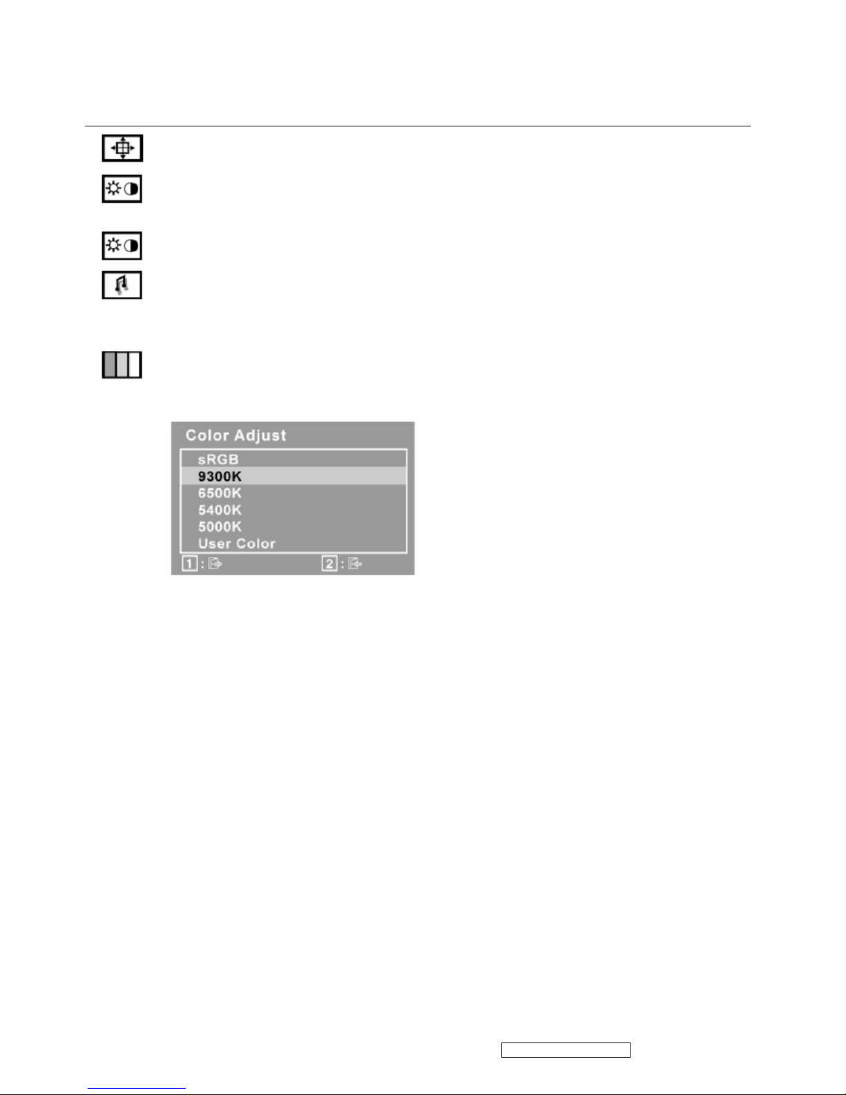
Control Explanation
Auto Image Adjust sizes and centers the screen image automatically.
Contrast adjusts the difference between the image background (black level) and the
foreground (white level).
Brightness adjusts background black level of the screen image.
Audio Adjust
Volume increases the volume, decreases the volume, and mutes the audio.
Mute temporarily silences audio output.
Color Adjust provides several color adjustment modes, including preset color temperatures
and a User Color mode which allows independent adjustment of red (R), green (G), and
blue (B). The factory setting for this product is 6500K (6500 Kelvin).
sRGB-This is quickly becoming the industry standard for color management, with support
being included in many of the latest applications. Enabling this setting allows the LCD
display to more accurately display colors the way they were originally intended. Enabling
the sRGB setting will cause the Contrast and Brightness adjustments to be disabled.
9300K-Adds blue to the screen image for cooler white (used in most office settings with
fluorescent lighting).
6500K-Adds red to the screen image for warmer white and richer red.
5400K-Adds green to the screen image for a darker color.
5000K-Adds blue and green to the screen image for a darker color.
User Color Individual adjustments for red (R), green (G), and blue (B).
1. To select color (R, G or B) press button [2].
2. To adjust selected color, press pand q
Important: If you select RECALL from the Main Menu when the product is set to a Preset
Timing Mode, colors return to the 6500K factory preset.
VG2021m-1 Confidential - Do Not Copy
ViewSonic Corporation
11
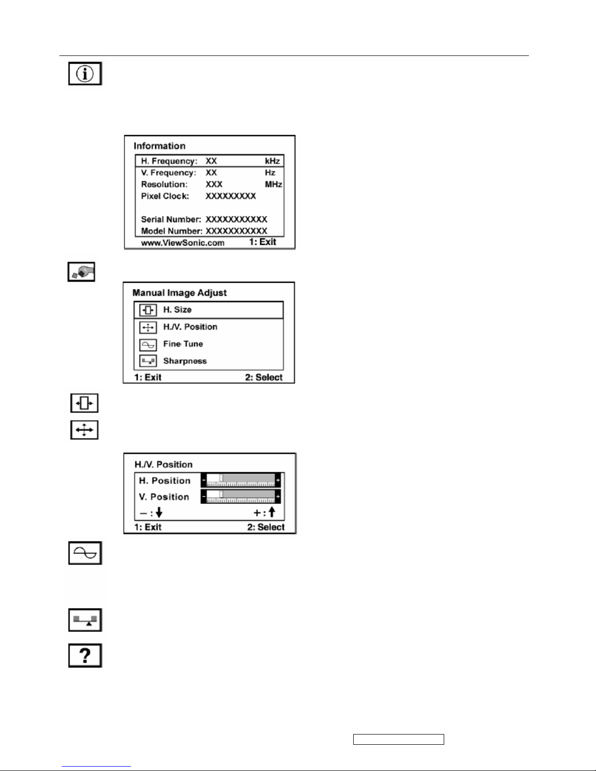
Control Explanation
Information displays the timing mode (video signal input) coming from the
graphics card in the computer, the LCD model number, the serial number, and
the ViewSonic® website URL. See your graphics card’s user guide for
instructions on changing the resolution and refresh rate (vertical frequency).
NOTE: VESA 1400 x 1050 @ 60Hz (recommended) means that the resolution
is 1400 x 1050 and the refresh rate is 60 Hertz.
Manual Image Adjust Sub-menu
H. Size (Horizontal Size) adjusts the width of the screen image.
H./V. Position (Horizontal/Vertical Position) moves the screen image left or
right and up or down.
Fine Tune sharpens the focus by aligning text and/or graphics with pixel boundaries.
NOTE: Try Auto Image Adjust first.
Sharpness adjusts the clarity and focus of the screen image.
Setup Menu displays the menu shown below
VG2021m-1 Confidential - Do Not Copy
ViewSonic Corporation
12
Language Select allows the user to choose the language used in the menus and control
screens.
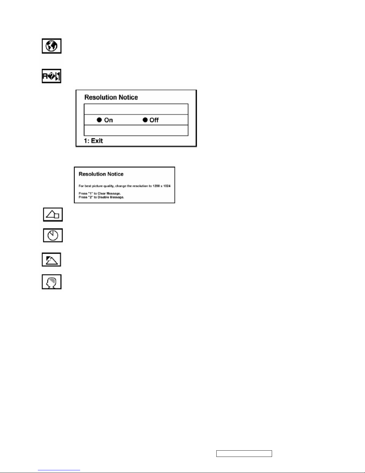
Resolution Notice allows the user to enable or disable this notice.
If you enable the Resolution Notice shown above and your computer is set at a resolution
other than 1400 x 1050, the following screen appears.
OSD Position allows the user to move the OSD menus and control screens.
OSD Timeout sets the length of time the OSD screen is displayed. For example, with a “30
second” setting, if a control is not pushed within 30 seconds, the display screen disappears.
OSD Background allows the user to turn the OSD background On or Off.
Memory Recall returns the adjustments back to factory settings if the display is operating
in a factory Preset Timing Mode listed in the Specifications of this manual.
VG2021m-1 Confidential - Do Not Copy

ViewSonic Corporation
13
4. Circuit Description
The TSUM57AK is total solution graphics processing IC for LCD monitors with panel resolutions up to
SXGA. It is configured with a high-speed integrated triple-ADC/PLL, an integrated DVI receiver, a high
quality display processing engine, and an integrated output display interface that can support RSDS panel
interface format. To further reduce system costs, the TSUM57AK also integrates intelligent power
management control capability for green-mode requirements and spread- spectrum support for EMI
management.
The TSUM57AK incorporates the world’s first coherent oversampled RGB graphics ADC in a monitor
controller system. The oversampling ADC samples the input RGB signals at a frequency that is much
higher than the signal source pixel rate. This can preserve details in the video signal that ordinarily would
be lost due to input signal jitter or bandwidth limitations in non-oversampled systems. The TSUM57AK
also incorporates a new Dynamic Frame Rate (DFR) generator for the digital output video to the display
panel that preserves the advantages of a fixed output clock rate, while eliminating the output end of frame
short-line.
VG2021m-1 Confidential - Do Not Copy

ViewSonic Corporation
14
5. Adjustment Procedure
A. Function Test and Alignment Procedure
1. All Modes Reset
You should do “All Model Reset” (Refer to Chap 3. Hot Keys for Function Controls) first.
This action will allow you to erase all end-user’s settings and restore the factory defaults.
2. Auto Image Adjust
The Auto Adjust is aimed to offer a best screen quality by built-in ASIC. For optimum screen
quality, the user has to adjust each function manually.
A.Turn the computer and LCD monitor on.
B. Press the ‘Auto’ button on monitor keypad to Auto Adjust.
C. The LCD monitor will start the Auto Adjust process automatically and run for 10 consecutive
seconds, during which time you will notice the image change.
3. Firmware
Test Patten: Burn in Model (Refer to Chap3. Hot Keys for Function Control)
-Make sure the F/W is the latest version.
4. DCC
Test Patten: EDID program
-Make sure it can pass test program.
5. Window Shut Down
Test Signal: 1400*1050@60Hz
Test Pattern:
Checkered Pattern Every One Pixel (50%Green & 50%Blue)
Inspection Item: Flicker, Mura
6. Window BG
Test Signal: 1400*1050@60Hz
Test Pattern:
Window standard pattern
Inspection Item: Line Defect, Function Defect & Mura
7. 25 Gray
Test Signal: 1400*1050@60Hz
Test Pattern:
Full Screen 25% White (Gray)
Inspection Item: Particle, Line Defect & Mura
VG2021m-1 Confidential - Do Not Copy
ViewSonic Corporation
15
8. 50 Gray
Test Signal: 1400*1050@60Hz
Test Pattern:
Full Screen 50% White (Gray)
Inspection Item: Bright Dot, Particle, Line Defect & Mura
9. White Box
Test Signal: 1400*1050@60Hz
Test Pattern:
Window standard pattern
Inspection Item: Particle, Line Defect, Power, Image Remain & Mura
10. Black Box
Test Signal: 1400*1050@60Hz
Test Pattern:
Window standard pattern
Inspection Item: Bright Dot, Line Defect & Power
11. RED
Test Signal: 1400*1050@60Hz
Test Pattern:
Full Screen Red
Inspection Item: Bright Dot, Partial & Line Defect
12. Green
Test Signal: 1400*1050@60Hz
Test Pattern:
Full Screen Green
Inspection Item: Bright Dot, Partial & Line Defect
13. Blue
Test Signal: 1400*1050@60Hz
Test Pattern:
Full Screen Green
Inspection Item: Bright Dot, Partial & Line Defect
VG2021m-1 Confidential - Do Not Copy
ViewSonic Corporation
16
14. Gray_Scale_0-100_V64
Test Signal: 1400*1050@60Hz
Test Pattern:
Vertical 64 (256) Gray Scale (Right → Left,From 0 to 100% White)
Inspection Item: Line Defect & Function Defect
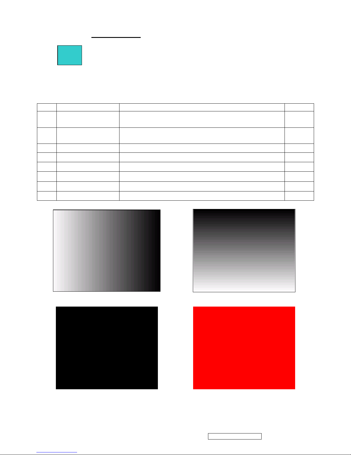
15. Function Test Display pattern
Item
Pattern Description Remark
1
Gray_Scale_0-100_V
Vertical 64 (256) Gray Scale
(right→left,From 0 to 100% White)
Figure 1
2
Gray_Scale_0-100_H
Horizontal 64 (256) Gray Scale
(up→down,From 0 to 100% White)
Figure 2
3
Black Full Screen Black Figure 3
4
Red Full Screen 50% Red Figure 4
5
Green Full Screen 50% Green Figure 5
6
Blue Full Screen 50% Blue Figure6
7
White Full Screen White Figure7
8
Black_Tile Black Tile Under White Background Figure 8
Figure 1 Figure 2
Figure 3 Figure 4
VG2021m-1 Confidential - Do Not Copy

ViewSonic Corporation
17
Figure 5 Figure 6
Figure 7 Figure 8
VG2021m-1 Confidential - Do Not Copy

BIOS update procedure
1. To setup ISP environment
Hardware:
PC or Notebook , Parallel(Printer) cable , ISP tool( Fig 1)
Software:
ISP driver .
If the O.S. was Win2000 or Win XP please have to install
PORT95NT.exe
Fig1
In order to ensure can execute ISP program, please set BIOS in PC or Notebook as Fig 2
Fig 2
ViewSonic Corporation
18
VG2021m-1 Confidential - Do Not Copy
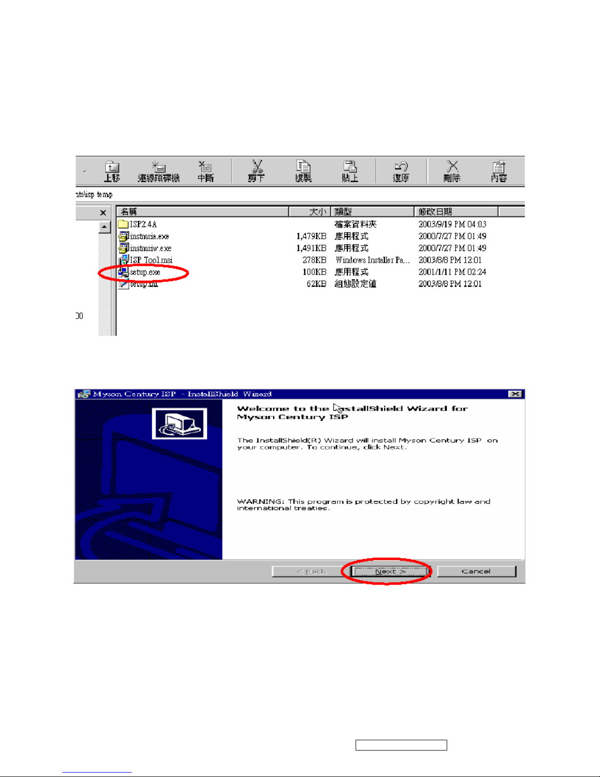
2. Install ISP
2.1 User could download ISP driver and PORT95NT install file from Myson Century website (http://www.myson.com.tw )
2.2 After extracting the zip file, the total files list as Fig 2.2, and double click the file of setup.exe to install.
Fig 2.2
2.3 Press “Next” button to continue., see Fig 2.3
Fig 2.3
ViewSonic Corporation
19
VG2021m-1 Confidential - Do Not Copy
 Loading...