

Page 1
VG175 ViewPanel
User Guide
Guide de l’utilisateur
Bedienungsanleitung
Guía del usuario
Guida dell’utente
Guia do usuário
Användarhandbok
Руководство пользователя
Podręcznik użytkownika
®
With Landscape and Portrait Display Modes
Full 17.4" Diagonal Viewable Screen
Page 2

Contents
For Your Records ..................................................................2
Getting Started
Package Contents .................................................................3
Precautions ...........................................................................3
Quick Installation ...................................................................4
Installation of Wall Mount (Optional) .................................5
LCD Screen Protector (Optional) ......................................5
Landscape/Portrait Modes ....................................................6
To Raise and Lower the Display ...........................................6
Using the ViewPanel
Setting the Timing Mode .......................................................7
Adjusting the Screen Image ..................................................8
Other Information
Specifications ......................................................................13
Troubleshooting...................................................................14
Customer Support ...............................................................15
Cleaning the ViewPanel ......................................................16
Limited Warranty .................................................................17
E
N
G
L
I
S
H
Appendix
Power Cord Safety Guidelines ............................................18
FCC Information .................................................................. 19
CE Conformity ..................................................................... 19
ViewSonic VG175 1
Page 3
Copyright © ViewSonic Corporation, 2000. All right reserved.
Macintosh and Power Macintosh are registered trademarks of Apple Computer, Inc.
E
N
G
L
I
S
H
Microsoft, Windows, Windows NT, and the Windows logo are registered trademarks of Microsoft
Corporation in the United States and other countries.
ViewSonic, the three birds logo, OnView, ViewMatch, and ViewMeter are registered trademarks of
ViewSonic Corporation.
VESA is a registered trademark of the Video Electronics Standards Association. DPMS and DDC
are trademarks of VESA.
E
NERGY STAR
As an E
NERGYSTAR
E
Disclaimer: ViewSonic Corporation shall not be liable for technical or editorial errors or omissions
contained herein; nor for incidental or consequential damages resulting from furnishing this
®
is a registered trademark of the U.S. Environmental Protection Agency (EPA).
NERGYSTAR
®
partner, ViewSonic Corporation has determined that this product meets the
®
guidelines for energy efficiency.
material, or the performance or use this product.
In the interest of continuing product improvement, ViewSonic Corporation reserves the right to
change product specifications without notice. Information in this document may change without
notice.
No part of this document may be copied, reproduced, or transmitted by any means, for any purpose
without prior written permission from ViewSonic Corporation.
Electronic Warranty Registration
To meet your future needs, and to receive any additional product information as it
becomes available, please register your ViewPanel's warranty on the Internet at:
http://www.viewsonic.com
Product Name:
Model Number:
Document Number:
Serial Number:
Purchase Date:
2 ViewSonic VG175
For Your Records
VG175
VLCDS21833-1
VG175_UG-47_1b
_______________
_______________
Page 4

Getting Started
Congratulations on your purchase of a VG175 color ViewPanel®.
Important! Save the original box and all packing material for future shipping needs.
NOTE:
Microsoft
Windows NT
The word “Windows” in this user guide refers to the following
®
operating systems: Windows 95, Windows 98, Windows 2000,
®
.
Package Contents
Your VG175 package includes:
• VG175 ViewPanel with video cable
• Setup Guide
• Power cords
• Video cable
• AC/DC Adapter
• ViewSonic Wizard CD-ROM (including user guide PDF file and INF/ICM
display optimization files)
IMPORTANT:
The supplied INF file ensures compatibility with Windows
operating systems, and the ICM file (Image Color Matching) assures accurate
on-screen colors.
Precautions
• For best viewing conditions sit at least
18" from the ViewPanel.
• AVOID TOUCHING THE SCREEN
WITH YOUR FINGERS. Oils from the
skin are difficult to remove.
• NEVER REMOVE THE REAR
COVER. The ViewPanel contains
high-voltage parts. You may suffer
serious injury if you touch these parts.
• Avoid exposing the ViewPanel to direct
sunlight or another heat source. The
ViewPanel should be facing away from
direct sunlight to reduce glare.
• Always handle your ViewPanel with
care when moving it.
• Place your ViewPanel in a well
ventilated area. Do not place anything on
the ViewPanel that prevents adequate
dissipation of heat.
• Ensure the area around the ViewPanel is
clean and free of moisture.
• Do not place heavy objects on the
ViewPanel, video cable, or power cord.
• If smoke, abnormal noise, or strange
odor is present, immediately switch the
ViewPanel off and call your dealer or
ViewSonic. It is dangerous to continue
using the ViewPanel.
E
N
G
L
I
S
H
ViewSonic VG175 3
Page 5
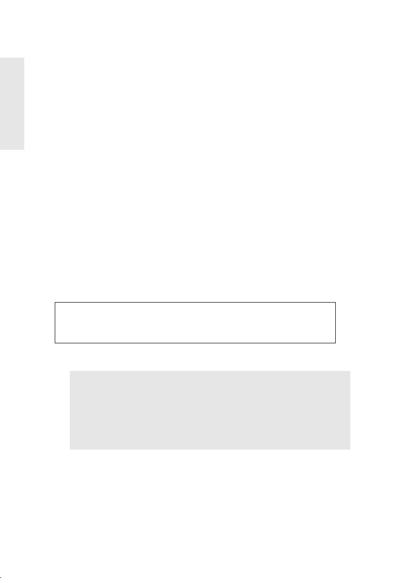
Quick Installation
Video cable to
computer
Power cord
with adapter
to wall plug
E
N
G
L
I
S
H
1 Connect video cable
Make sure both the ViewPanel®and computer
are powered OFF.
• Rotate the ViewPanel 90
easier connection of cables).
• Connect the video cable to the computer, then
to the ViewPanel.
Macintosh
require a Macintosh adapter. Attach the adapter
to the computer and plug the video cable into
the adapter.
To order a ViewSonic
contact ViewSonic. See “Customer Support” on
page 15.
®
users: Models older than G3
clockwise (to allow
°
®
Macintosh adapter
2 Connect power cord and AC/DC
adapter
Connect the power cord and AC/DC adapter
from the ViewPanel to a properly grounded AC
outlet.
3 Power-ON ViewPanel and computer
Power-ON the ViewPanel, then power-ON the
computer. This sequence (ViewPanel before
computer) is very important.
NOTE: At this point Windows
users may receive a message askingthem to install
the ViewSonic VG175 INF file.
®
95, 98, and 2000
4 Install INF and ICM files
(1) Insert the ViewSonic Wizard CD-ROM into
your computer's CD-ROM drive.
NOTE: If your computer does not have a
CD-ROM drive, see Customer Support in this
user guide.
(2) Wait for the CD-ROM to auto-start.
NOTE: If your computer does not auto-start:
double-click on the CD-ROM icon in the
Windows Explorer, then double-click on
install.exe
(3) Follow the on-screen instructions.
5 Windows users: Set the Timing
Mode (resolution and refresh rate)
Example: 1280 X 1024 @ 60 Hz.
For instructions on changing the resolution and
refresh rate, see the user guide for your
computer's graphics card.
Installation is complete.
Enjoy your new VG175 ViewPanel.
To be best prepared for any future customer
service needs:
• Write the serial number (see back of the
ViewPanel) in “For Your Records” on page 2.
• Register the warranty of your ViewPanel on
the Internet at:
www.viewsonic.com
4 ViewSonic VG175
Page 6
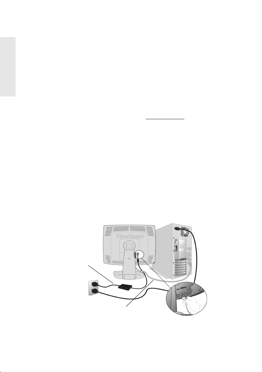
Installation of Wall Mount (Optional)
Remove the plate
on the back of
the ViewPanel
Remove (4) screws
The holes are threaded
for wall mount
To obtain a wall-mounting kit, contact ViewSonic or your local dealer. To
convert your ViewPanel from a desk-mounted to a wall-mounted display, do the
following:
Disconnect Power.
1
Lay the ViewPanel
2
face down on a towel
or blanket.
Remove the square
3
plastic cover from the
back panel to reveal
the screw heads.
Remove the (4) screws.
4
Attach the ViewPanel
5
to the wall using the
wall mounting kit and
instructions.
E
N
G
L
I
S
H
LCD Screen Protector (Optional)
Special slots have been added to the front panel
of your VG175 to enable you to install an
optional LCD screen protector.
This special poly carbonate sheet (not shown in
the graphic) is easy to install and will protect the
LCD panel from scratches. Contact ViewSonic
Customer Support for more information.
ViewSonic VG175 5
Page 7
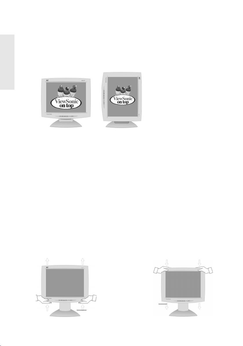
Landscape/Portrait Modes
NOTE: Before using the
portrait display mode, install
the PerfectPortrait®software
included with your VG175
ViewPanel. Follow the
instructions that accompany
the software.
Raise the display
Lower the display
E
N
G
L
I
S
H
The VG175 ViewPanel can operate in either Landscape or Portrait mode
(see below).
To switch from landscape (default) to Portrait mode, do the following:
Face the front of the ViewPanel.
1
Pull the bottom of the ViewPanel toward you to tilt the bottom away from
2
the base.
Manually rotate the VG175 clockwise 90 degrees.
3
PerfectPortrait software is compatible with most PCI and AGP graphics (video)
cards. For information on compatible graphics cards and approved hardware
configurations, go to the ViewSonic website at www.viewsonic.com.
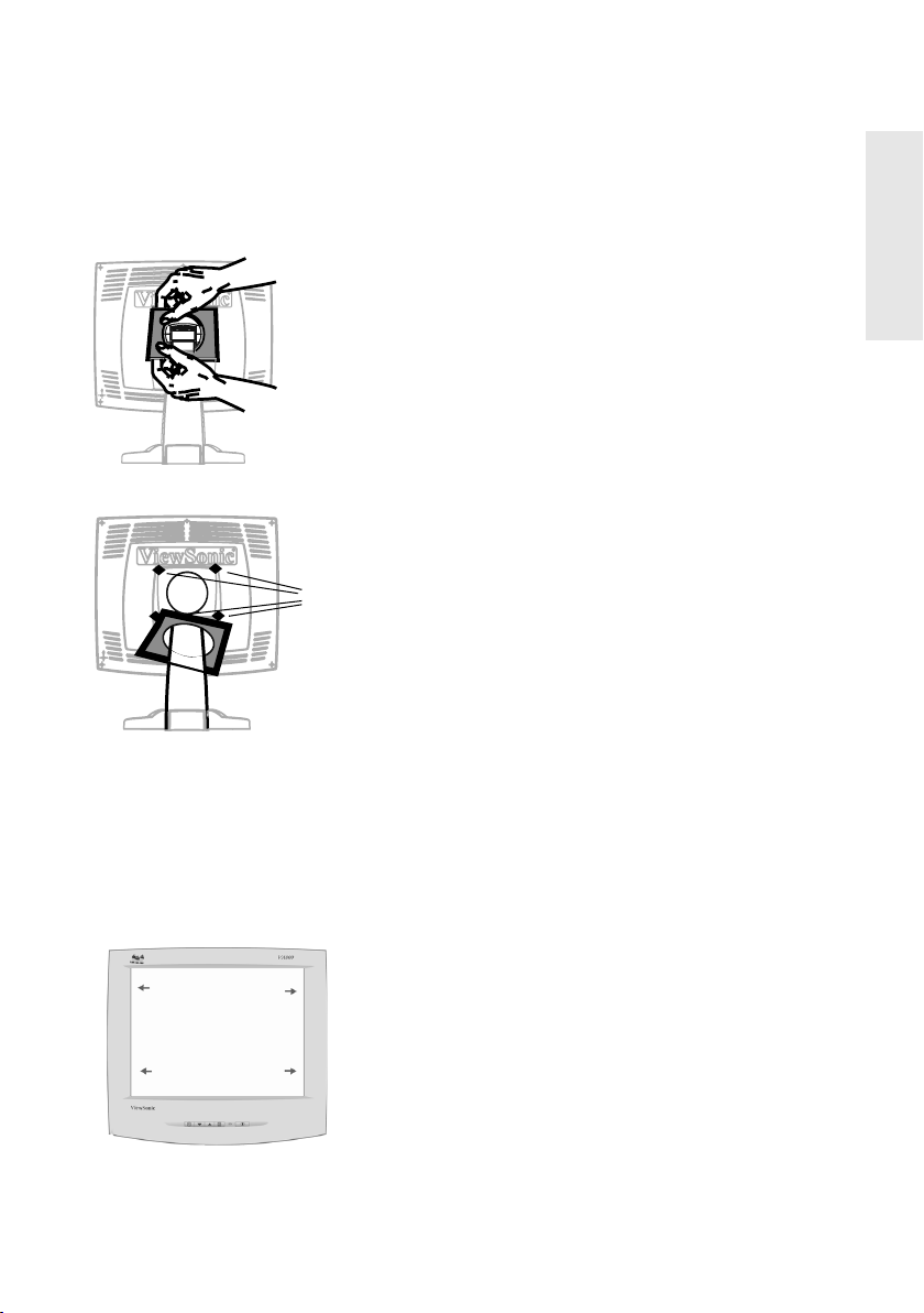
To Raise and Lower the Display
You can easily raise and lower the display panel (the head) manually. As you
face the front of the display, grasp each side of the head and pull upward or
downward to meet your personal preference.
6 ViewSonic VG175
Page 8

Using the ViewPanel
Setting the Timing Mode
Setting the timing mode is important for maximizing the quality of the screen
image and minimizing eye strain. The timing mode consists of the resolution
(example 1280 x 1024) and refresh rate (or vertical frequency--example 60
Hz). After setting the timing mode, use the OnView
page 10) to adjust the screen image.
The recommended timing mode for this ViewPanel is:
VESA®1280 x 1024 @ 60 Hz
To set the Timing Mode:
1 Set the resolution
Settings > Desktop Area (Screen Area for Windows 95 and newer) > set
the resolution.
2 Set the refresh rate
: Right-click on the Windows®desktop > Properties >
: See your graphic card's user guide for instructions.
®
controls (beginning on
E
N
G
L
I
S
H
WARNING:
maximum refresh rate of 75 Hz. Doing so may result in permanent damage to
your ViewPanel.
Do not set the graphics card in your computer to exceed the
ViewSonic VG175 7
Page 9

Adjusting the Screen Image
Scroll through menu
options and adjust the
displayed control.
Displays, saves
changes to, and exits
theMainMenu.
Power On/Off
Displays the control screen for the
highlighted control and toggles
between control pairs.
Power light
Main Menu
With OnView controls
Front Control Panel
Button 2 selects to the
highlighted control screen.
E
N
G
Use the buttons on the front control panel to display and adjust the OnView
controls from ViewSonic®. The controls are explained in the steps at the top of
the next page and are further explained in “Main Menu Controls” on page 10.
®
L
I
S
H
8 ViewSonic VG175
Page 10

To adjust the screen image:
To display the Main Menu as shown below, press button [1].
1
To highlight a control you want to adjust, press the up ▲ or down ▼ button
2
on the display’s front control panel to scroll up or down the Main Menu: for
example, Contrast.
To select the highlighted control, for example, Contrast, press button [2]. A
3
control screen for the selected control appears as shown below.
E
N
G
L
I
S
H
To adjust the selected control, press the up ▲ or down ▼ button.
4
To save the adjustments and exit the menu, press button [1].
5
The following tips may help you optimize your display:
• Adjust your computer's graphic card so that it outputs a video signal of 1280
x 1024 @ 60Hz to the VG175. (Look for instructions on changing the refresh
rate in your graphic card's user guide.) Then, use Auto Sync to size and
center the screen image.
• If necessary, make small adjustments using the Fine Tune control.
• Adjust the Smoothing control so that the screen image looks focused, crisp,
and sharp when using a resolution other than 1280 x 1024.
ViewSonic VG175 9
Page 11

Main Menu Controls
E
N
G
L
I
S
H
The menu items shown below can be adjusted by using the up
buttons.
Control Explanation
Video Source selects between two analog video inputs.
Note: Onscreen display will show Video Source 1 or Video
▲ and down ▼
Source 2, depending upon the currently selected input
source.
Auto Contrast
compensates for any differences in video
card output levels.
Press button [2] to activate Auto Contrast.
Shortcut: Press the up arrow [
▲] button. The Auto Contrast
control screen appears and bypasses the Main Menu.
Contrast adjusts the difference between the image
background (black level) and the foreground (white level).
Brightness
adjusts background black level of the screen
image.
ViewMatch® Color
provides several color options: preset
color temperatures and USER which allows you to adjust
red (R), green (G), and blue (B) individually.
Preset 1— Adds red to the screen image for warmer white
and richer red.
Preset 2— Adds blue to the screen image for cooler white
(used in most office settings with fluorescent lighting).
User — Individual adjustments for red, green, and blue.
Important: If you select Recall from the Main Menu when
the product is set to a Preset Timing Mode, colors return to
the factory Preset 1.
10 ViewSonic VG175
Page 12

Control Explanation
LCD Adjust positions and fine tunes the onscreen image.
PC/MAC selects the type of computer that will be used with
the ViewPanel.
H Size (Horizontal Size) adjusts the width of the screen
image.
H Position (Horizontal Position) moves the screen
image to the left or to the right.
V Position (Vertical Position) moves the screen image
up or down.
Fine Tune sharpens the focus by aligning the illuminated
text or graphic characters.
Auto Sync automatically sizes, centers, and fine tunes the
video signal to eliminate noise and distortion.
Press button [2] to activate.
Note: Windows users start from the Windows desktop.
E
N
G
L
I
S
H
ViewSonic VG175 11
Page 13

Control Explanation
E
N
G
L
I
S
H
Misc provides access to the miscellaneous control features
shown below.
H OSD Position allows you to move the menu and control
screen horizontally.
VOSDPositionallows you to move the menu and control
screen vertically
Smoothing eliminates jagged edges around text characters
for easier reading.
NOTE:
Only for resolutions lower than 1024 x 768.
Background turns the blue OSD background on or off.
This affects the background of the OnView display only.
Viewmeter displays information regarding the current
input signal coming from the graphics card of the computer.
Recall returns adjustments to the original factory settings if
the display is operating in a factory Preset Timing Mode
listed in this user guide.
Exception: This control does not affect changes made with
the User Color control.
NOTE:
12 ViewSonic VG175
Using this control resets color to Preset 1.
Page 14

Other Information
Specifications
LCD
Maximum
viewing angles
Input signal
Compatibility
Resolution
Powe r
Display area
Operating
conditions
Storage
conditions
Dimensions
Weight
Regulations
Power saving
modes
Preset Timing
Mode
Ty p e
Color Filter
Glass surface
Horizontal
Ve rt ic a l
Video
Sync
PC
Macintosh
Recommended
Supported
Voltage
Consumption
Full Scan 345.6 mm (H) x 276.5 mm (V)
Temperature
Humidity
Temperature
Humidity
Physical
(ViewPanel
Net
On
Suspend
Off
E
17.4" (full 17.4" viewable diagonal area),
TFT (Thin Film Transistor), Active Matrix LCD,
0.27 mm pixel pitch
RGB vertical stripe
Anti-Glare
160°
160°
RGB analog (0.7/1.0 Vp-p, 75 ohms)
H./V Separated (TTL), Composite sync, Sync-On-Green
:30-82 kHz, fv:50-75 Hz
f
h
®
*
®
VGA up to 1280 x 1024 Non Interlaced
Powe r Ma cint osh®up to 1280 x 1024
1280 x 1024 @ 60 Hz
1152 x 870 @ 75 Hz 640 x 480 @ 60, 72, 75 Hz
1024 x 768 @ 60, 70, 72, 75 Hz 640 x 400 @ 70 Hz
832 x 624 @ 75 Hz 720 x 400 @ 70 Hz
800 x 600 @ 56, 60, 72, 75 Hz 640 x 350 @ 70 Hz
81-264 VAC (Universal) via external DC Converter Brick
65 W (max)
17.4” Diagonal
32° F to + 104° F(0° Cto+40° C)
10% to 90% (no condensation)
-4° F to + 140° F (-20° Cto+60° C)
10% to 90% (no condensation)
460 mm (W) x 460 mm (H) x 240 mm (D)
18.1" (W) x 18.1" (H) x 9.4" (D)
)
8.5 kg (18.7 lb) ViewPanel
UL, CSA, FCC-B, CB, CE, DOC-B, TUV/ERGO (covers ISO
13406-2 & MPRII), TUV/GS, TCO99, E2000, VCCI, BSMI,
NEMKO, SEMKO, DEMKO, FIMKO, B-MARK, NOM, PCT+
HYGIENIC, ARGENTINA, S-MARK, C-TICK, CCIB + CCEE
60 W (green LED) Normal
<3W (amber LED) Max
<3 W (amber LED)
Pre-adjusted to VESA®1280 x 1024 @ 60 Hz
Warning: Do not set the graphics card in your computer to
exceed the maximum vertical refresh rate. Doing so may result in
permanent damage to the ViewPanel.
®
only
N
G
L
I
S
H
*
Macintosh computers older than G3 require a ViewSonic®, Macintosh adapter. To order an adapter,
contact ViewSonic.
ViewSonic VG175 13
Page 15

Troubleshooting
E
N
G
L
I
S
H
No power
• Make sure power button (or switch) is ON.
• Make sure A/C power cord is securely connected to the DC power supply and
®
the power supply is firmly connected to the ViewPanel
.
• Plug another electrical device (like a radio) into the power outlet to verify that
the outlet is supplying proper voltage.
Power on but no screen image
• Make sure the video cable supplied with the ViewPanel is tightly secured to
the video output port on the back of the computer. If the other end of the
video cable is not attached permanently to the ViewPanel, tightly secure it to
the ViewPanel. The ViewPanel comes with a 15 pin mini D-sub signal cable.
• Adjust brightness and contrast.
®
• If you are using an Macintosh
older than G3, you need a Macintosh adapter.
Wrong or abnormal colors
• If any colors (red, green, or blue) are missing, check the video cable to make
sure it is securely connected. Loose or broken pins in the cable connector
could cause an improper connection.
• Connect the ViewPanel to another computer.
®
• If you have an older graphics card, contact ViewSonic
for a non-DDC
adapter.
Entire screen image scrolls (rolls) vertically
• Make sure video input signals are within the ViewPanel's specified frequency
range.
• Try the ViewPanel with another power source, graphics card, or computer
system.
• Connect the video cable securely.
Control buttons do not work
• Press only one button at a time.
14 ViewSonic VG175
Page 16

Customer Support
For the most expedient answer to your question, do the following:
Check Troubleshooting (on the previous page).
1
For assistance contact your reseller.
2
For further assistance see the contact information listed below.
3
If contact information for your country or region is not listed below, ask your
reseller to refer you to a service center.
NOTE:
You will need to provide the serial number (on the back of the product).
Country/Region T = Telephone
F=FAX
United States
Canada
United Kingdom T: 0800 833 648
Europe, Middle East,
Baltic countries, and
North Africa
Australia (contact reseller) -----------------------------
New Zealand T: 64-3-366-1135
T: (800) 688-6688
F: (909) 468-1202
T: (800) 688-6688
F: (909) 468-1202
F: 0044 (0)1293 643910
T: 0044 (0)1293 643900
F: 0044 (0)1293 643910
F: 64-3-366-7006
Email
vstech@viewsonic.com
vstech@viewsonic.com
----------------------------
-----------------------------
mbarlass@vistech.co.nz
E
N
G
L
I
S
H
Singapore/Southeast
Asia
Other Asia/Pacific
countries and Indian
Peninsula
South Africa T: 27-11-314-0002
T: 65-273-4018
F: 65-273-1566
T: 886-2-2248-4072
F: 886-2-2240-8238
F: 27-11-314-0002
viewsonicspore@pacific.net.sg
vsi@viewsonic.com.tw
atscom@mweb.co.za
ViewSonic VG175 15
Page 17

Cleaning the ViewPanel
E
N
G
L
I
S
H
• MAKE SURE THE ViewPanel®IS TURNED OFF.
• NEVER SPRAY OR POUR ANY LIQUID DIRECTLY ONTO THE
SCREEN OR CASE.
To clean the screen:
Wipe the screen with a clean, soft, lint-free cloth. This removes dust and
1
other particles.
If still not clean, apply a small amount of non-ammonia, non-alcohol based
2
glass cleaner onto a clean, soft, lint-free cloth, and wipe the screen.
To clean the case:
Use a soft, dry cloth.
1
If still not clean, apply a small amount of a non-ammonia, non-alcohol
2
based, mild non-abrasive detergent onto a clean, soft, lint-free cloth, then
wipe the surface.
Disclaimer
®
ViewSonic
does not recommend the use of any ammonia or alcohol-based
cleaners on the ViewPanel screen or case. Some chemical cleaners have been
reported to damage the screen and/or case of the ViewPanel. ViewSonic will not
be liable for damage resulting from use of any ammonia or alcohol-based cleaners.
16 ViewSonic VG175
Page 18

Limited Warranty
VIEWSONIC LCD VIEWPANEL
What the warranty covers:
ViewSonic
warranty period. If a product proves to be defective in material or workmanship during the warranty
period, ViewSonic will, at its sole option, repair or replace the product with a like product. Replacement
product or parts may include remanufactured or refurbished parts or components.
How long the warranty is effective:
ViewSonic LCD ViewPanels are warranted for three (3) years for all parts including the light source and
three (3) years for all labor from the date of the first consumer purchase.
Who the warranty protects:
This warranty is valid only for the first consumer purchaser.
What the warranty does not cover:
1. Any product on which the serial number has been defaced, modified or removed.
2. Damage, deterioration or malfunction resulting from:
3. Removal, installation, and set-up service charges.
How to get service:
1. For information about receiving service under warranty, contact ViewSonic Customer Support.
2. To obtain service under warranty, you will be required to provide (a) the original dated sales slip, (b) your
3. Take or ship the product freight prepaid in the original container to an authorized ViewSonic
4. For additional information or the name of the nearest ViewSonic service center, contact
Limitation of implied warranties:
THERE ARE NO WARRANTIES, EXPRESS OR IMPLIED, WHICH EXTEND BEYOND THE
DESCRIPTION CONTAINED HEREIN INCLUDING THE IMPLIED WARRANTY OF
MERCHANTABILITY AND FITNESS FOR A PARTICULAR PURPOSE.
Exclusion of damages:
VIEWSONIC'S LIABILITY IS LIMITED TO THE COST OF REPAIR OR REPLACEMENT OF THE
PRODUCT. VIEWSONIC SHALL NOT BE LIABLE FOR:
1. DAMAGETOOTHERPROPERTYCAUSEDBYANYDEFECTSINTHEPRODUCT,DAMAGES
2. ANY OTHER DAMAGES, WHETHER INCIDENTAL, CONSEQUENTIAL OR OTHERWISE.
3. ANY CLAIM AGAINST THE CUSTOMER BY ANY OTHER PARTY.
Effect of state law:
This warranty gives you specific legal rights, and you may also have other rights which vary from state
to state. Some states do not allow limitations on implied warranties and/or do not allow the exclusion of
incidental or consequential damages, so the above limitations and exclusions may not apply to you.
Sales outside the U.S.A. and Canada:
For warranty information and service on ViewSonic products sold outside of the U.S.A. and Canada,
contact ViewSonic or your local ViewSonic dealer.
ViewSonic LCD Warranty (V2.0) Release Date: 10-15-1999
®
warrants its products to be free from defects in material and workmanship during the
a. Accident, misuse, neglect, fire, water, lightning, or other acts of nature, unauthorized product
modification, or failure to follow instructions supplied with the product.
b. Repair or attempted repair by anyone not authorized by ViewSonic.
c. Any damage of the product due to shipment.
d. Removal or installation of the product.
e. Causes external to the product, such as electrical power fluctuations or failure.
f. Use of supplies or par ts not meeting ViewSonic’s specifications.
g. Normal wear and tear.
h. Any other cause which does not relate to a product defect.
You will need to provide your product's serial number.w
name, (c) your address, (d) a description of the problem, and (e) the serial number of the product.
service center or ViewSonic.
ViewSonic.
BASED UPON INCONVENIENCE, LOSS OF USE OF THE PRODUCT, LOSS OF TIME, LOSS OF
PROFITS, LOSS OF BUSINESS OPPORTUNITY, LOSS OF GOODWILL, INTERFERENCE WITH
BUSINESS RELATIONSHIPS, OR OTHER COMMERCIAL LOSS, EVEN IF ADVISED OF THE
POSSIBILITY OF SUCH DAMAGES.
®
E
N
G
L
I
S
H
ViewSonic VG175 17
Page 19

Appendix
Figure A1
Figure A2
E
N
G
L
I
S
H
Power Cord Safety Guidelines
CAUTION: Use a power cable that is properly grounded. Always use the AC cords listed for each country.
In other areas, use an AC cord which meets local safety standards.
USA................. UL
Canada............. CSA
Germany.......... VDE
AC PLUG CORD PRECAUTIONS FOR THE UNITED KINGDOM
FOR YOUR SAFETY PLEASE READ THE FOLLOWING TEXT CAREFULLY.
IF THE FITTED MOULDED PLUG IS UNSUITABLE FOR THE SOCKET OUTLET THEN THE PLUG SHOULD BE
CUT OFF AND DISPOSED OF SAFELY.
THERE IS A DANGER OF SEVERE ELECTRICAL SHOCK IF THE CUT OFF PLUG IS INSERTED INTO AN APPROPRIATE
SOCKET.
If a new plug is to be fitted, please observe the wiring code as shown below.
If in any doubt, please consult a qualified electrician.
WARNING:
IMPORTANT:
If the coloured wires of the mains lead of this appliance do not correspond with the coloured markings identifying the
terminals in your plug, proceed as follows:
The wire which is coloured GREEN-AND-YELLOW must be connected to the terminal in the plug which is marked by
the letter E or by the Earth symbol or coloured GREEN or GREEN-AND-YELLOW.
The wire which is coloured BLUE must be connected to the terminal in the plug which is marked with the letter N or
coloured BLACK. The wire which is coloured BROWN must be connected to the terminal in the plug which is marked
with the letter L or coloured RED.
THIS APPLIANCE MUST BE EARTHED.
The wires in this mains lead are coloured in accordance with the following code:
Green-and-Yellow: Earth
Blue: Neutral
Brown: Live
Switzerland ..... SEV
Britain ............. BASE/BS
Japan ............... Electric Appliance Control Act
IMPORTANT NOTICE CONCERNING POWER CORD SELECTION
The power cord set for this unit has been enclosed and has been selected according to the country of
destination and must be used to prevent electric shock. Use the following guidelines if it is necessary to
replace the original cord set, or if the cord set is not enclosed.
The female receptacle of the cord set must meet CEE-22 requirements and will look like (Figure 1 below):
For the United States and Canada
In the United States and Canada the male plug is a NEMA5-15 style (Figure 2), UL Listed, and CSA
Labeled. For units which are mounted on a desk or table, type SVT or SJT cord sets may be used. For
units which sit on the floor, only SJT type cord sets may be used. The cord set must be selected according
to the current rating for your unit. Please consult the table below for the selection criteria for power cords
used in the United States and Canada.
For European Countries
In Europe you must use a cord set which is appropriate for the receptacles in your country. The cord set is
HAR-Certified, and a special mark that will appear on the outer sheath, or on the insulation of one of the
inner conductors.
If you have any questions concerning which proper power cord to use, please consult with the dealer from
whom you have purchased the product.
Cord Type Size of Conductors in Cord Maximum Current Rating of Unit
SJT 18 AWG
SVT 18 AWG
16 AWG
14 AWG
17 AWG
10 Amps
12 Amps
12 Amps
10 Amps
12 Amps
18 ViewSonic VG175
Page 20

FCC Information
This equipment has been tested and found to comply with the limits for a Class B digital device, pursuant to
part 15 of the FCC Rules. These limits are designed to provide reasonable protection against harmful
interference in a residential installation. This equipment generates, uses, and can radiate radio frequency
energy, and if not installed and used in accordance with the instructions, may cause harmful interference to
radio communications. However, there is no guarantee that interference will not occur in a particular
installation. If this equipment does cause harmful interference to radio or television reception, which can be
determined by turning the equipment off and on, the user is encouraged to try to correct the interference by
one or more of the following measures:
• Reorient or relocate the receiving antenna.
• Increase the separation between the equipment and receiver.
• Connect the equipment into an outlet on a circuit different from that to which the receiver is connected.
• Consult the dealer or an experienced radio/TV technician for help.
FCC Warning
To assure continued FCC compliance, the user must use grounded power supply cord and the provided
shielded video interface cable with bonded ferrite cores. If a BNC cable is going to be used, use only a
shielded BNC(5) cable. Also, any unauthorized changes or modifications not expressly approved by the
party responsible for compliance could void the user's authority to operate this device.
Notice for Germany
The x-rays generated in this unit are shielded sufficiently. High voltage: Max. 30 kV. Also, for ergonomic reasons, we
recommend that you do not display blue characters on a dark background. Doing so may produce insufficient
contrast that could lead to eye strain.
Notice for Japan
This is a Class B product based on the standard of the Voluntary Control Council for Interference from Information
Technology Equipment (VCCI). If this is used near a radio or television receiver in a domestic environment, it may
cause radio interference. Install and use the equipment according to the instruction manual.
CE Conformity
The device complies with the requirements of the EEC directive 89/336/EEC as amended
by 92/31/EEC and 93/68/EEC Art.5 with regard to “Electromagnetic compatibility,” and 73/
23/EEC as amended by 93/68/EEC Art.13 with regard to “Safety.”
E
N
G
L
I
S
H
ViewSonic VG175 19
Page 21

NOTES
E
N
G
L
I
S
H
20 ViewSonic VG175
Page 22

ViewSonic
Corporation
381 Brea Canyon Road
Walnut, CA 91789
Tel (909) 869-7976
Tel (800) 688-6688
Fax (909) 468-1202
 Loading...