

ViewSonic VG150m-1, VG150mb-1, VLCDS23587-3W, VLCDS23587-4W Service Manual
ViewSonic VG150m-1
Model No.VLCDS23587-3W
Service Manual
15” Color TFT LCD Display
( VG150m-1_SM_547-R ev.1 a –Dec 2 0 02 )
ViewSonic
“ 381 Brea Canyon Road, Walnut, California 91789 USA - (800) 888-858
3
VG150mb-1
VLCDS23587-4W
Copyright
Copyright © 2002 by ViewSonic Corporation. All rights reserved. No part of this
publication may be reproduced, transmitted, transcribed, stored in a retrieval system, or
translated into any language or computer language, in any form or by any means,
electronic, mechanical, magnetic, optical, chemical, manual or otherwise, without the prior
written permission of ViewSonic Corporation.
Disclaimer
ViewSonic makes no representations or warranties, either expressed or implied, with
respect to the contents hereof and specifically disclaims any warranty of merchantability or
fitness for any particular purpose. Further, ViewSonic reserves the right to revise this
publication and to make changes from time to time in the contents hereof without obligation
of ViewSonic to notify any person of such revision or changes.
Trademarks
ViewSonic is a registered trademark of ViewSonic Corporation. All other trademarks used
within this document are the property of their respective owners.
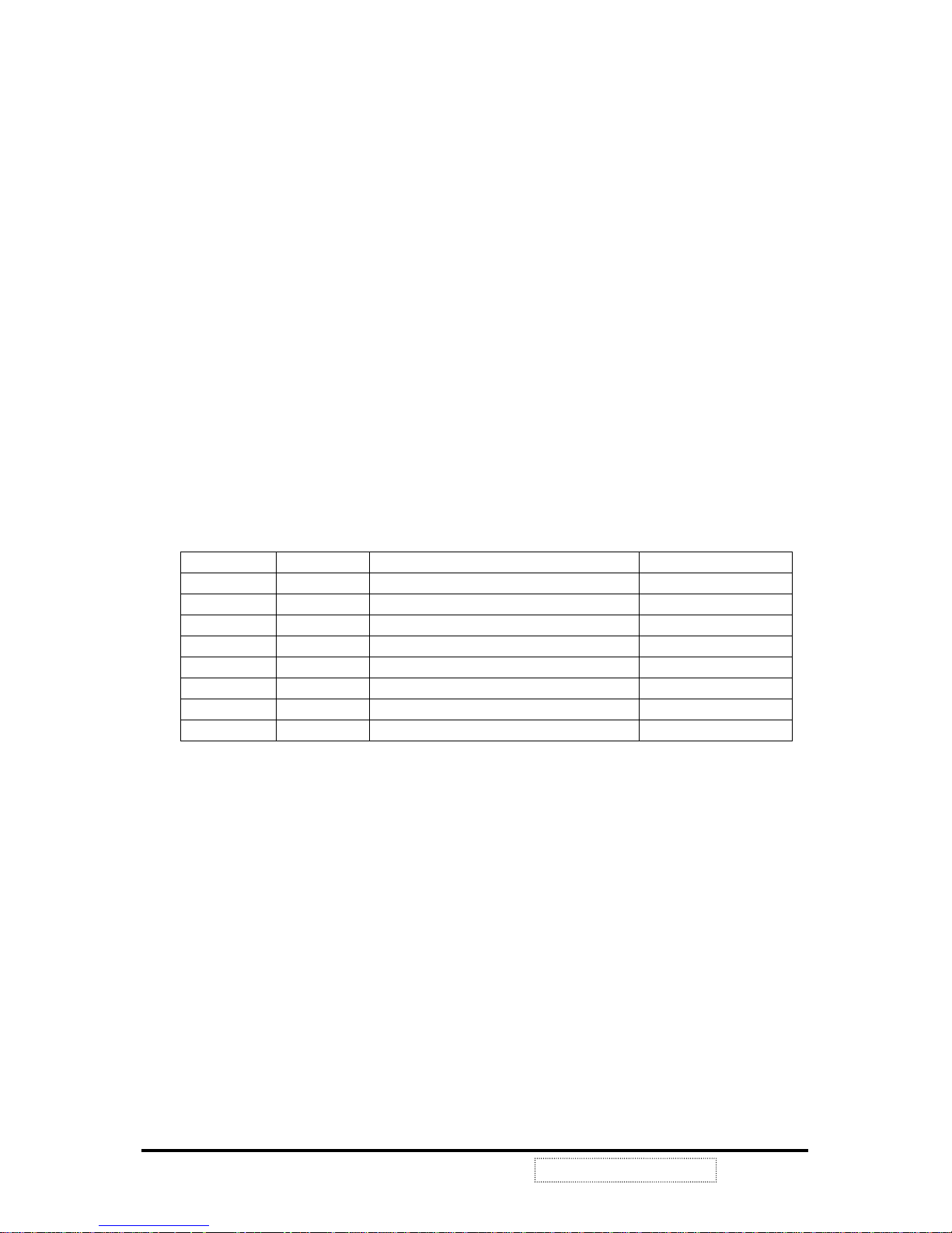
Revision History
Revision Date Description Approval
ViewSonic Corporation
i
Confidential --Do Not Copy VG150m/mb
1a 12/17/02 Initial Release DCN-2256 C.Shen

TABLE OF CONTENTS
Chapter 1 Precautions and Notices…………………………………………1
Chapter 2 Specification…………………………………………………….....3
2-1 General Specification………………………………………....3
2-2 Factory Preset Timing…………………………………….......4
2-3 D-Sub Connector Pin Assignment…………………………...5
Chapter 3 Disassembly / Assembly Instructions………………………...6
Chapter 4 Electronic Circuit Description…………………………………..7
4-1 Block Diagram………………………………………………….7
4-2 Main Board I/O Connections………………………………….8
4-3 Inverter Board I/O Connections………………………………8
4-4 Theory of Circuit Operation……………………………………9
Chapter 5 Adjustment………………………………………………………….24
Chapter 6 Troubleshooting Flow Chart…………………………………..26
6-1 Figures of Wave Form……………………………………….26
6-2 Troubleshooting Flow Chart…………………...……………29
Chapter 7 Schematic Diagrams…………………………………………….33
Chapter 8 PCB Layout…………………………………………………………37
Chapter 9 Exploded Diagram and Mechanical Parts List…………………41
Chapter 10 Recommended Spare Parts List………………………………….43
Chapter 11 Complete Parts List……………………………………………...44
ViewSonic Corporation
ii
Confidential --Do Not Copy VG150m/mb
Appendix
Reader's Response
1. Precautions and Notices
Prior to using this manual, please ensure that you have carefully followed all the
procedures outlined in the user manual for this product.
Read all of these instructions.
Save these instructions for later use.
Follow all warnings and instructions marked on the product.
Do not use this product near water.
This display should be installed on a solid horizontal base.
When cleaning, use only a neutral detergent cleaner with a soft damp cloth. Do not
spray with liquid or aerosol cleaners.
Do not expose this display to direct sunlight or heat. Hot air may cause damage to
the cabinet and other parts.
Adequate ventilation must be maintained to ensure reliable and continued
operation and to protect the display from overheating. Do not block ventilation slots
and openings with objects or install the display in a place where ventilation may be
hindered.
Do not install this display near a motor or transformer where strong magnetism is
generated. Images on the display will become distorted and the color irregular.
Do not allow metal pieces or objects of any kind fall into the display from ventilation
holes.
Slots and openings in the cabinet and the back or bottom are provided for
ventilation, to ensure reliable operation of the product and to protect it from
overheating, those openings must not be blocked or covered. The openings should
never be blocked by placing the product on a bed, sofa, rug, or other similar surface.
This product should never be placed near or over a radiator or heat register. This
product should not be placed in a built-in installation unless proper ventilation is
provided.
ViewSonic Corporation
1
Confidential --Do Not Copy VG150m/mb
FCC Statement
This equipment has been tested and found to comply with the limits of Class B digital device, pursuant to part
15 of the FCC Rules. These limits are designed to provide reasonable protection against harmful interference
in a residential installation. This equipment generates and can radiate radio frequency energy, and if
not installed and used in accordance with the instructions, may cause harmful interference to radio
communication. However, there is no guarantee that the interference will not occur in a particular installation.
If this equipment does cause unacceptable interference to radio or television reception, which can be
determined by turning the equipment off and on, the user is encouraged to try to correct the interference by
one or more of following measures
Κ
Reorient or relocate the receiving antenna.
Increase the separation between equipment and receiver.
Connect into an outlet on circuit different from that to which the receiver is connected.
Consult the dealer or an experience radio/TV technician for help.
FCC Warning
To assure continued FCC compliance the user must use a grounded power supply cord and the provided
shielded video interface cable with bonded ferrite cores. Also, unauthorized changes or modifications to
ViewSonic products will void the usercs authority to operate this device. Thus ViewSonic will not be held
responsible for the product and its safety.
CE Certification
This device complies with the requirements of the ECC directive 89/3366/EEC with regard to
sElectromagnetic compatibility.s
Safety Guidelines
Caution: Use a power cable properly grounded. Always use the AC Mains cords listed below for each area
Κ
USA
(UL)
Canada
(CSA)
Germany
(VDE)
Switzerland
(SEV)
Britain
(BASE/BS)
Japan
(Electric Appliance Control Act)
In other areas, use AC cord which meets the local safety standards.
ViewSonic Corporation
2
Confidential --Do Not Copy VG150m/mb
2. Specification
2-1 General Specification
ViewSonic Corporation
3
Confidential --Do Not Copy VG150m/mb
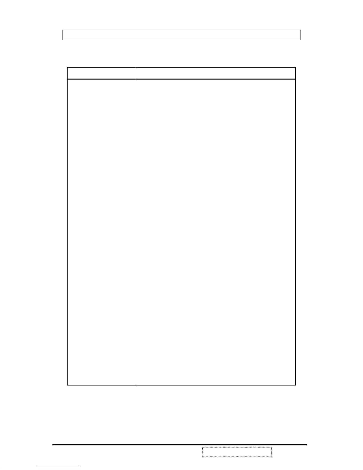
Characteristic Description
LCD Panel Mitsubishi 15.0” AA150XC01, 0.297mm (H/V), Anti-glare
Maximum Viewing Angles Horizontal: 150 degrees @ CRЊ10
Vertical: 110 degrees @ CRЊ10
Signal Input VideoΚRGB analog
SyncΚH.V. Separate Sync, H.V. Composite Sync
(TTL Compatible), Sync. On Green
HorizontalΚ30 to 62KHz
Vertical Κ50 to 75Hz
Connector Analog: 15 Pin Mini D-Sub
Maximum Resolution 1024x768
Video Bandwidth 85 MHz nominal
Display Area 304.1 mm (H) x 228.1 mm (V)
Power Voltage 87~264VAC @ 47~63 Hz
Power Consumption 40W max. (Adaptor plus monitor)
Operating Conditions Temperature : 32л to 104л (0к to 40к)
Humidity : 10% to 90% (no condensation)
Altitude : 0 to +3,000 meters
Storage Conditions Temperature : -4л to +140л (-20к to +60к)
Humidity : 10% to 90% (no condensation)
Altitude : 0 to +12,000 meters
Mechanical Dimensions Width: 359.0mm / 14.13”
Height: 325.0mm / 12.8”
Depth: 190.5mm / 7.5”
Depth side view panel w/o base: 49.0mm / 1.92”
Monitor Weight: 3.3Kg / 7.3 lbs
Package Dimensions Width: 480.0mm / 18.9“
Height: 425.0mm / 16.7”
Depth: 110.0mm / 4.3”
Gross: 5.1Kg (11.2 lbs)
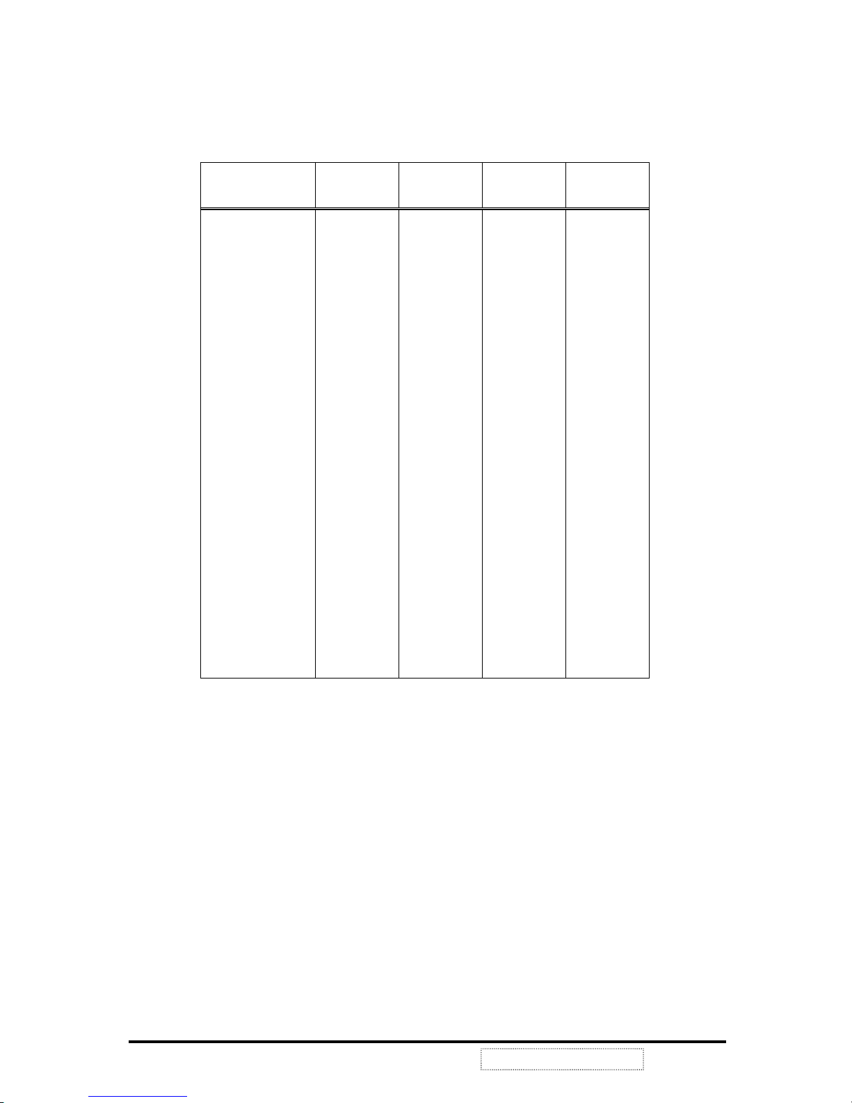
2-2 Factory Preset Timing
This timing chart is already preset for the TFT LCD monitors.
ViewSonic Corporation
4
Confidential --Do Not Copy VG150m/mb
Timing Horizontal
Polarity
Horizontal
Frequency
Vertical
Polarity
Vertical
Frequency
VGA 640x350 + 31.47 kHz - 70.09 Hz
VGA 720x400 - 31.46 + 70.08
VGA 640x400 - 31.46 + 70.08
VGA 640x480 - 31.47 - 60.05
VESA 640x480 - 37.86 - 72.81
VESA 640x480 - 37.50 - 75.00
MAC 640x480 Composite 35.00 Ѻ 66.66
VESA 800x600 + 35.15 + 56.25
VESA 800x600 + 37.87 + 60.31
VESA 800x600 + 48.07 + 72.18
VESA 800x600 + 46.87 + 75.00
MAC 832x624 SOG 37.86 Ѻ 72.80
VESA 1024x768 - 48.36 - 60.00
VESA 1024x768 - 56.47 - 70.06
VESA 1024x768 - 58.03 - 71.91
VESA 1024x768 + 60.02 + 75.02
MAC 1024x768 Composite 60.24 Ѻ 74.92
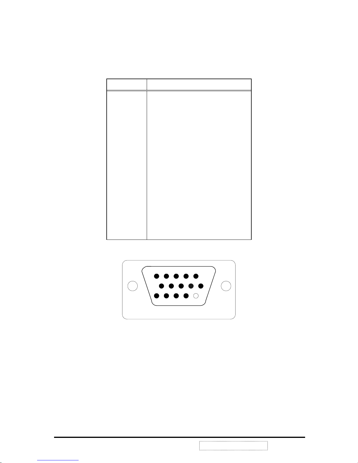
2-3 D-Sub connector Pin Assignment
The TFT LCD analog display monitors use a 15 Pin Mini D-Sub connector
as video input source.
Pin Number Pin Description
1 Red video input
2 Green video input
3 Blue video input
4 Ground
5 Ground
6 R video ground
7 G video ground
8 B video ground
9 +5V
10 Ground
11 No Connection
12 (SDA)
13 Horizontal sync (Composite sync)
14 Vertical sync
15 (SCL)
5
11
1
6
10
15
ViewSonic Corporation
5
VG150m/mb
Confidential --Do Not Copy
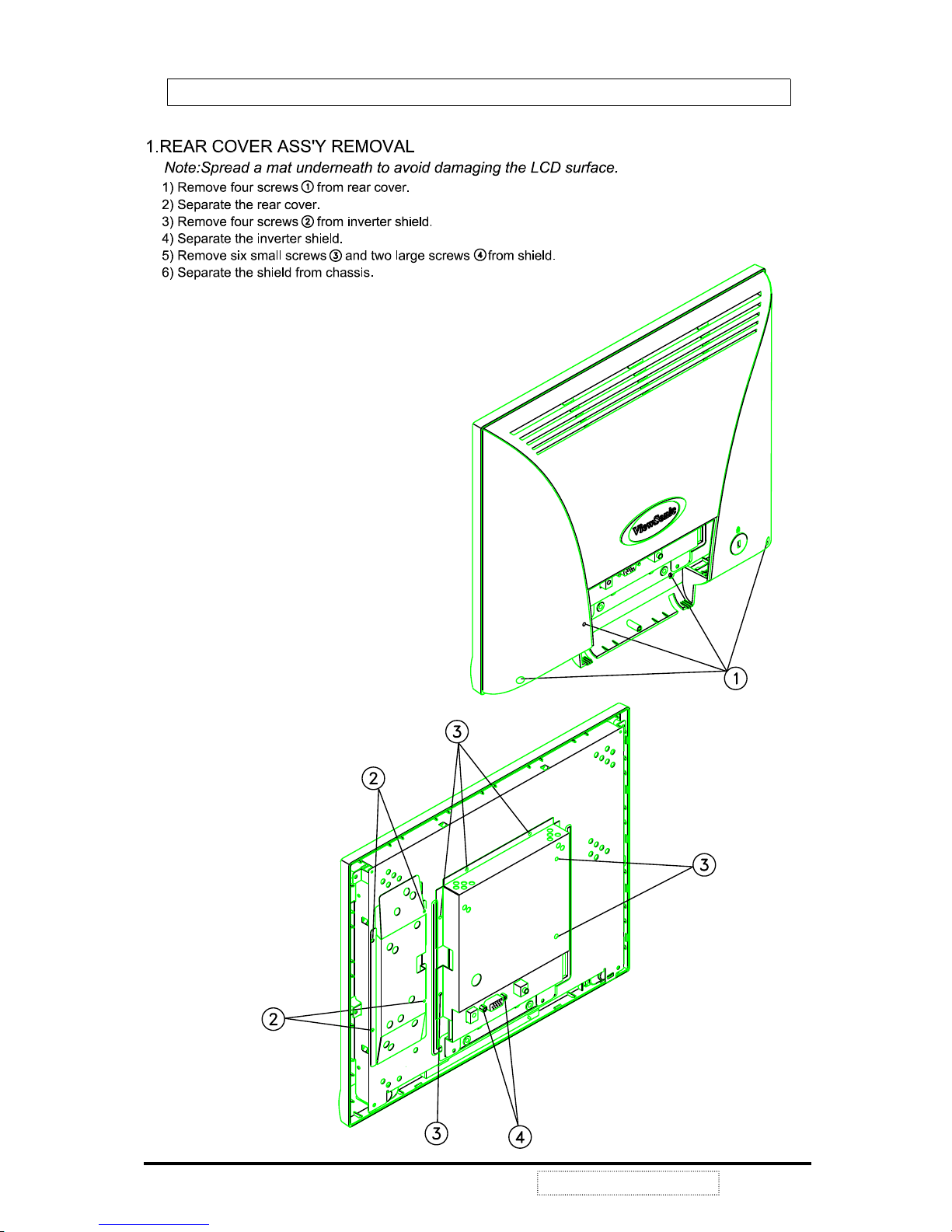
3. Disassembly / Assembly Instructions
ViewSonic Corporation
6
Confidential - Do Not Copy VG150m/mb
AUDIO IN
SPEAKER
AC Outlet
Adaptor
Main Board
Inverter
ControlBrightness
TFT
LCD
Panel
Digital
Signal
Analog
Signal
Video Card
12V
12V
VA C
Volume control & Mute on/off
Speaker
Audio in
DC/DC
Converter
+5V
VLCD
+3.3V
+12V
Clamp
Video Gain
Video Level
ADC
MUX
Scaling
Engine
Sync detect
Phase calibration
OSD Generator
OSD overlay
MCU port
Dithering
Output control
Output
LCD
Panel
R, G, B
Sync
Buffer
U6
SYNCMOS
SM5964
MCU
HS
VS
HS
VS
U1 MRT
MASCOT
R, G, B offset
Gamma control
Audio amp.
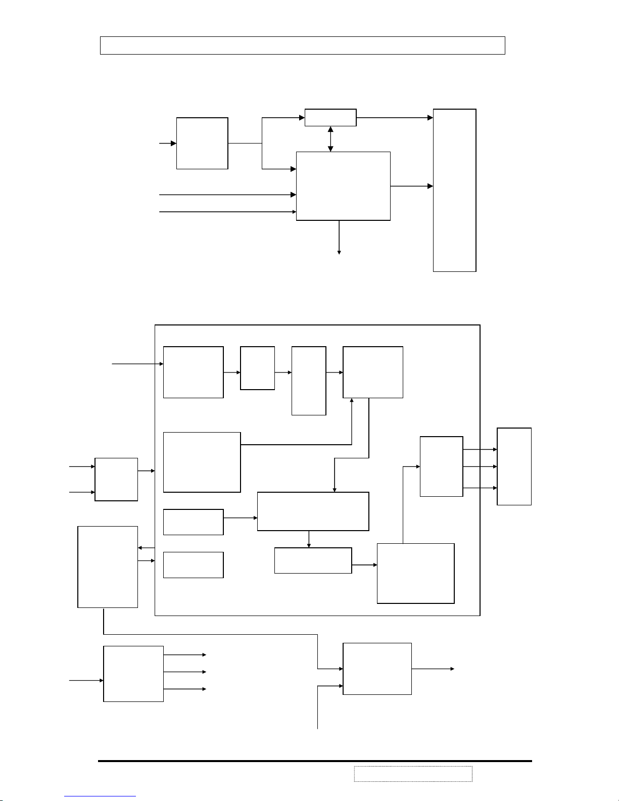
4. Electronic Circuit Description
4-1 Block Diagram
ViewSonic Corporation
7
Confidential --Do Not Copy VG150m/mb
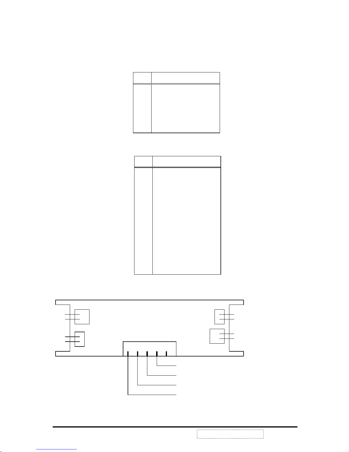
4-2 Main Board I/O Connections
P3 C
ONNECTION "INVERTER CONTROL"
Pin Description
1 N.C
2 CON
3 VEE
4 GND
5 VDD
ViewSonic Corporation
8
Confidential --Do Not Copy VG150m/mb
P5 CONNECTION "OSD CONTROL"
Pin Description
1 POW 1
2 GND
3 LED1
4 LED2
5 KEY1
6 KEY2
7 KEY3
8 KEY4
9 +
10 11 MUTE
4-3 Inverter Board I/O Connections
NOTE: MANUF ACTURER’S NAME MUST BE ON THE PRINTED SIDE FOR THE INVERTER BOARD TO
BE F A CING UP.
CON
VEE
GND
VDD
1
HV out
HV out
RTN
RTN
HV out
HV out
RTN
RTN
CN1
CN3
CN2
CN4
CN5
compatibles, Power PC and Macintosh. VG150m uses a TFT LCD panel with a 0.297mm pixel pitch,
provides 16.7 millions color images.
As the previous block diagram illustrates, VG150m uses a highly integrated solution (U1: Mascot V)
that combines a high performance ADC with an advanced image process controller. Using advanced
image scaling algorithms, Mascot V has intelligently adaptive sub-algorithms that will automatically
optimize the display quality for different images – the text is sharper and the graphics is smoother.
Furthermore, each TFT LCD monitor uses the 24LC02 (U14) chip to provide DDC1/2B¥ with
Analog Plug&Play, the DDC data format is EDID v1.3.
Digital process and control system allows users to control OSD menu values to change monitor
settings. The follow sections are major part discussions of the TFT LCD display control board.
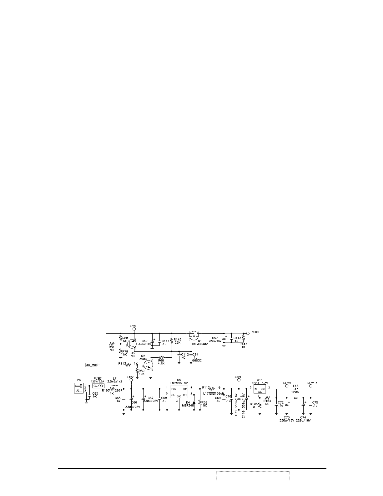
POWER SYSTEM
This product uses an external power adapter to provide DC+12V. It is the source of other voltages +5VX,
3.3VX, and VLCD.
The voltage of +5VX is produced by regulator LM2596-5V (U5) and external components that can realize DC
to DC conversion from +12V to +5V. For some chips (MPU, ADC) that are sensitive to any voltage variance,
we need LDO 1084-3.3V (U11) to produce a stable voltage 3.3VX.
There is still an important consideration about power consumption. We must greatly reduce the power
consumption even up to 90% in power saving mode. So we need to switch off the power that needn’t exist
when the system enters to this mode. We use the P-channel MOSFET TRLML6402 (Q1) to control the on/off
state of the panel’s power VLCD.
See FIG1-1.
FIG1-1
ViewSonic Corporation
9
Confidential --Do Not Copy VG150m/mb
4-4 Theory of Circuit Operation
VG150m/mb is a multi-frequency and multi-mode color TFT LCD monitor. It supports different
resolutions including XGA, SVGA, VGA and other various high resolution up to 1024x768 for IBM, PC
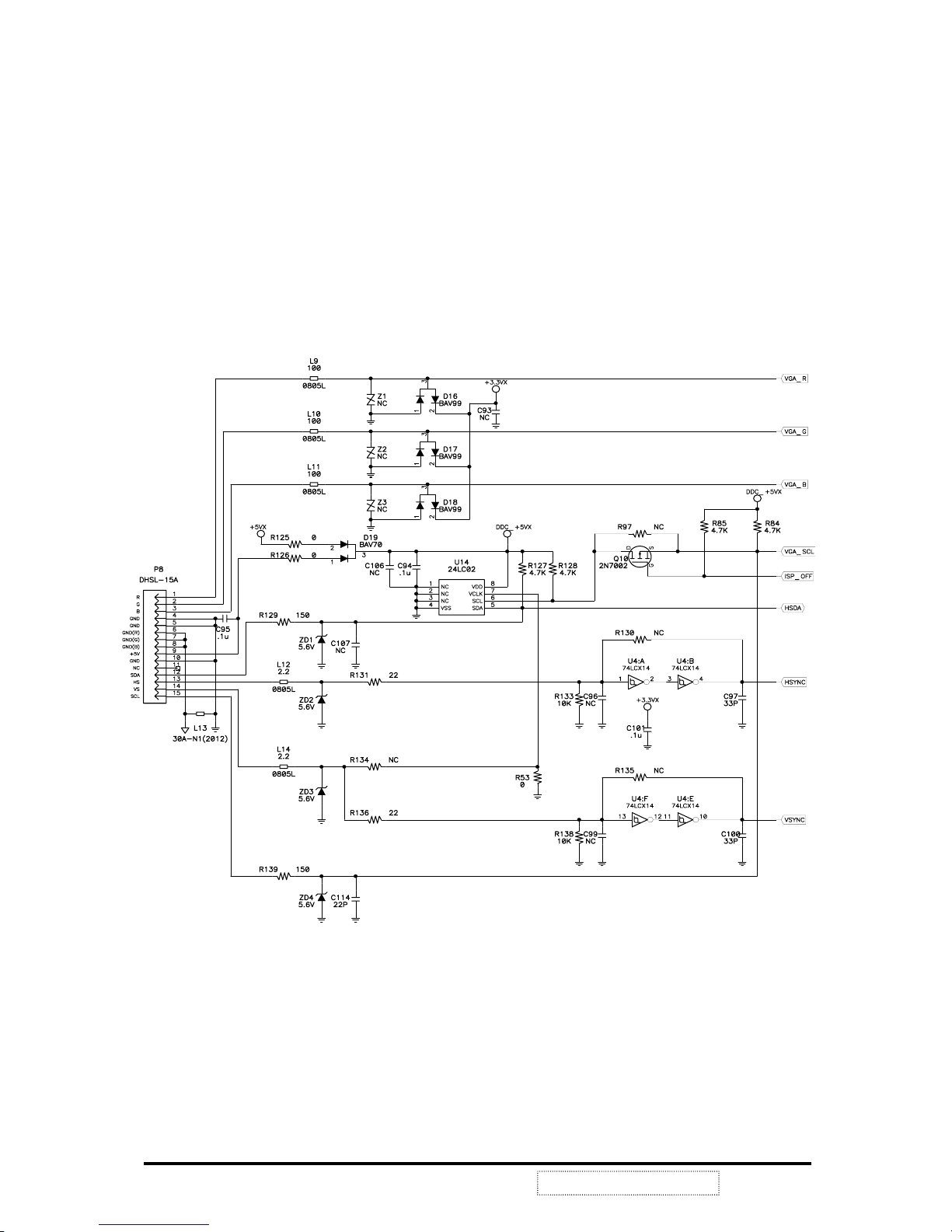
ANALOG SIGNAL INPUT and EDID
This product uses the internal function of Mascot V (U1) as a signal detector in order to support separate SYNC.
The analog input Horizontal and Vertical Synchronal signals pass through the Schmitt trigger buffer U4 to stabilize
then input to
Mascot U1 pin38 VGA_VSYNC, pin39 VGA_HSYNC or pin40 SOGI and the image processing.
Then
Mascot will detect the signal type if it is separate SYNC, composite SYNC or SOG. MPU (U6) reads the
input signal type from IIC protocol and does the correct procedure to generate the proper signals to the whole
system.
24LC02 (U14) chip provide DDC1/2B¥ with Analog Plug&Play , and the DDC data format is EDID v1.3.
See FIG1-2.
FIG1-2
ViewSonic Corporation
10
Confidential --Do Not Copy VG150m/mb
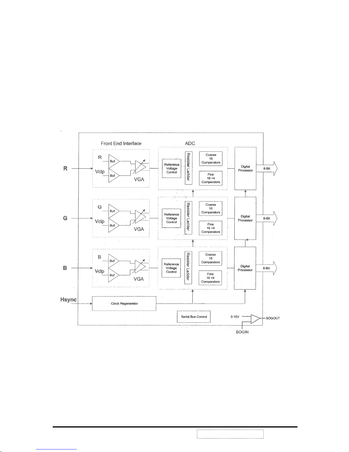
ANALOG to DIGITAL CONVERSION and PROCESSING
General Description of Mascot
Mascot V is a highly integrated solution (U1) that combines a high performance ADC with an advanced image
process controller . Using a dvanced ima ge scaling alg orithms, Mascot V has i nte lligently adaptive sub -algo rithms
that will automatically optimize the display quality for different images – the text is sharper and the graphics is
smoother.
The build-in analog interface includes an 80MHz, 8-bit 3-channel ADC, pre-amplifier, and VGA, allowing
seamless support to resolution from VGA to XGA. ADC function block diagram, see FIG3-1.
FIG3-1 ADC Functional Block Diagram
ViewSonic Corporation
11
Confidential --Do Not Copy VG150m/mb
Clock Re-Generator Functional Block Diagram
FIG3-2 Clock Re-Generator
ADC Block Description
Variable Gain Amplifier (VGA)
The front-end circuit is designed to provide four major functions:
Provide AC coupled interface with single-ended R/G/B input signal, convert single-ended sign al to
differential signal, and define common mode voltage.
Define CLAMPING voltage level with respect to ground for image brightness control.
Perform user programmable precision gain amplification.
Provide low impedance differential driver for ADC.
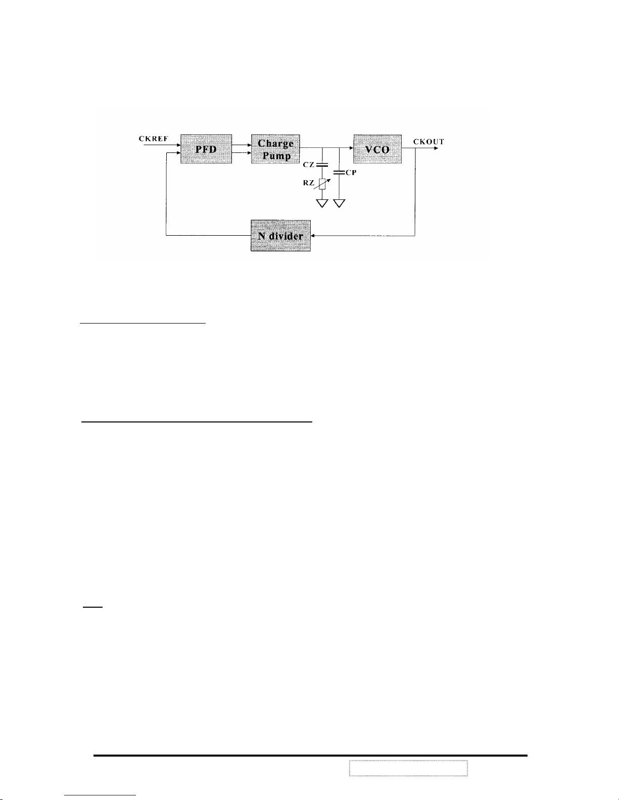
Phase Locked Loop (PLL) and Multi-Phase Generation
The phase locked loop (PLL) generates desired ADC sampling cl ock frequency (30 MHz to 80 MHz) from
external line clock CKREF. The exact frequency is register programmable and rel ated to the input line clock
CKREF as follows:
Freq (PLL) = Freq (CKREF)* Ndiv <12:0>
To ease the graphic interface, a phase programmable output clock is also generated for external use. The exact
phase delay with respect to VCO output clock is register programmable and can be formulated as follows:
T
DELAY
= IJ+Tclk * phase<4:0> / 32
Where there is a systematic delay. Due to the periodic nature of the clock, user can practically program the ADC
sampling anywhere with respect to data in the step size of Tclk/32.
ADC
Based on the requirements for this ADC (high speed, low power and small size). The sub ranging architecture is
used to minimize the number of comparators. The interpolation technique is also used to reduce the number of
preamplifiers. Two ide ntical 8bit ADC converters are used to increase the throughput of sub ranging ADC to one
conversion per clock cycle.
Each ADC operates in two-step sub range, i.e. coarse (3 bits) and fine (5 bits). One to four interpolations is
ViewSonic Corporation
12
Confidential --Do Not Copy VG150m/mb
performed in fine conversion step to minimize the number of preamplifier and to improve differential non-linearity
errors (DNL). In addition, in order to prevent potential error occurred during coarse conversion, digital error
correction technique is also used.
Clock Re-Generator Functional Block Diagram
FIG3-3 Clock Re-Generator
ViewSonic Corporation
13
Confidential --Do Not Copy VG150m/mb

Host Interface Control
Host interface controller is an interface between Mascot V and an external CPU. The access to Mascot V internal
internal registers, SRAM, programmable fonts, gamma tables, and ROM is performed by interface controller.
Mascot V provides single read/write and incremental read/write. Mascot V supports I2C bus and SPI protocols.
The bus protocol selection is determined by pin CONFIG[4], and Mascot V slave address is determined by pin
CONFIG[3:0].
GPIO (General Purpose Input/Output)
Gerenal Purpose Input/Output
Mascot V has provided three pins for general purpose input/output(GPIO); these pins can be programmed
as input or output pins; each GPIO pin has three registers for programming: GPIO Input/output control register,
GPIO output data register and GPIO input register; When GPIO is programmed as output pin, GPIO Input/output
control register is programmed as I (output), and the output data is provided by GPIO output data register; When
programmed as input pin, GPIO Input/output control register is programmed as 0(input), the input value can be
accessed thrugh GPIO input register.
PWM (Pulse Width Modulation)
Mascot V has provided two sets of PWM, each PWM can generate programmable periodic square waves. The
generated wave consists of low period and high period. The low period and high period can be programmed
separately. Each period can be programmed to be 0Д255 basic cycles. The basic cycle is defined by design,
which also has four kinds of basic cycles can be chosen by programming.
Sync Processor
Sync Processor is used to detect input source (analog RGB or 24-bit RGB) and generate interruption to an
external CPU if input source changes. Then the CPU can program Mascot V correctly according to different input
sources. Sync Processor can generate interruption when there are frequency changes, Hsync and Vsync polarity
changes, and when there is no input signal. Sync processor provides h_counter and v_counter which are stored
in registers CR0B, CR0C, CR0D, and CR0E. V frequency can be calculated by (refclk/64) / v_counter or
187.5kHz/ v_counter for using 12MHz refclk. H frequency is calculated by (refclk/512k) * h_counter or 46.5Hz *
h_counter or 46.5Hz * h_counter for using 12MHz refclk.
Mascot V Sync Processor can also support composite Sync and sync-on-green inputs. If sync Processor detects
the input source is composite sync or sync-on-green input, Mascot V will separate composite sync or sync-on-green
to Hsync and Vsync.
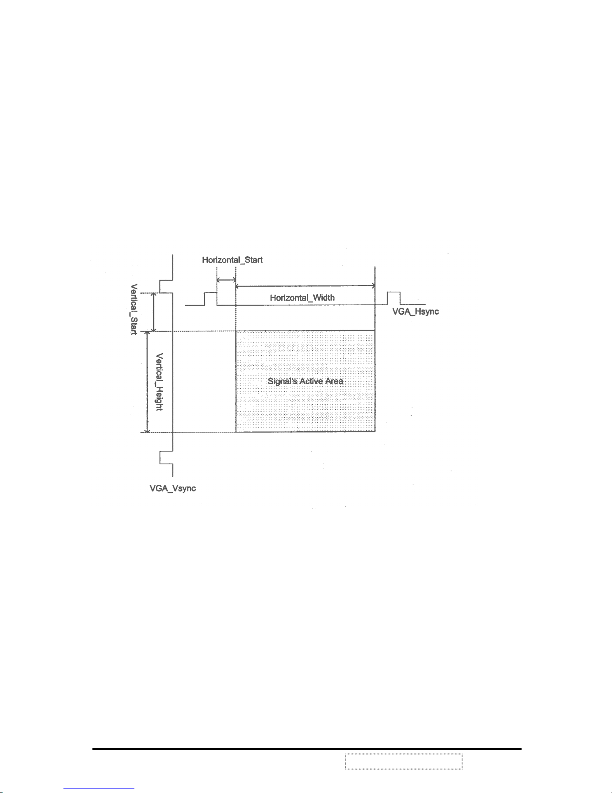
Calibration
Calibration block performs position calibration, color calibration and phase calibration. In position calibration,
non-zero data are detected horizontally and vertically. The Left most and right most positions and their
corresponding pitch can be found.Also Horizontal Total & Vertical Total are calculated.
Color calibration includes maximum color component detection, co lor read back from specified position and
maximum color difference in 2 neighboring pixels.
ViewSonic Corporation
14
Confidential --Do Not Copy VG150m/mb
In maximum color calibration, the pixel which has the maximum color component (based on CRB1[3:0]) can be
found. In color read back calibration, the color component (based on CRB[3:0]) for specific position can be read
back. In maximum color difference calibration, for specific color component, color differences between every 2
neighboring pixels are compared from first till the last pair within a frame. The position which has the largest color
difference with its neighboring data is found.
Phase calibration can report pixel mismatch in up to 32 frames based on 2 specified points.
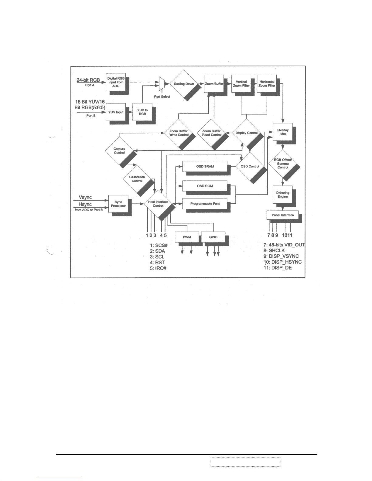
Capture Controller
Capture Controller is used to generate synchronization signals which are used for internal Mascot V. Within
Capture Controller block(FIG3-4), incoming data are processed, filtered, minimized and aligned with
controlling signals. Important internal synchronization signals in clude H_cnt, V_cnt, internal blank, and
end_of_frames.
FIG3-4 Capture Controller block
YUV to RGB Block
This block performs color space format conversion. Mascot V can convert 16 Bit YUV, RGB into 24 Bit RGB data
format.
Scaling Down
This block is used to conditionally drop incoming data if the incoming resolution is greater than 1024x768 which
is the physical resolution of the panel. A modified version of the Bresenham line-drawing algorithm is used to
determine which incoming data not to discard.
ViewSonic Corporation
15
Confidential --Do Not Copy VG150m/mb

Zoom Buffer
Zoom Buffer is used to store input data for scaling (zoom) function.
Zoom Buffer Write Control and Zoom Buffer Read Control
This Block generates write and read control signal to access zoom buffer.
Vertical Zoom Filter and Horizontal Zoom Filter
The
Mascot V scaling engine uses an advanced scaling technology and provides high quality scaling of text
images, graphic images and real-time video.
Display Control
FIG3-5 Display Control
ViewSonic Corporation
16
Confidential --Do Not Copy VG150m/mb
 Loading...