

ViewSonic VE710b-1,VE710s-1,VLCDS27998-2W,VLCDS279981W Service manual
Service Manual
ViewSonic VE710b/s-1
Model No. VLCDS27998-2W/-1W
17” Color TFT LCD Display
ViewSonic
(VE710b/s_1_SM_736- Rev. 1b – July 2004)
381 Brea Canyon Road, Walnut, California 91789 USA - (800) 888-8583
Copyright
Copyright
reproduced, transmitted, transcribed, stored in a retrieval system, or translated into any language or
computer language, in any form or by any means, electronic, mechanical, magnetic, optical, chemical,
manual or otherwise, without the prior written permission of ViewSonic Corporation.
Disclaimer
ViewSonic makes no representations or warranties, either expressed or implied, with respect to the
contents hereof and specifically disclaims any warranty of merchantability or fitness for any particular
purpose. Further, ViewSonic reserves the right to revise this publication and to make changes from time
to time in the contents hereof without obligation of ViewSonic to notify any person of such revision or
changes.
Trademarks
Optiquest is a registered trademark of ViewSonic Corporation.
ViewSonic is a registered trademark of ViewSonic Corporation.
All other trademarks used within this document are the property of their respective owners.
2004 by ViewSonic Corporation. All rights reserved. No part of this publication may be
¤
Revision History
Documents Number
DCN Number ECR Number
1a
1b
25/12/03
06/07/04
3742
4527
4342
To solve CPT panel shortage,
phase in QDI panel as the 2nd source
Description of Changes EditorRevision SM Editing Date
Initial Release
A. Lu
A .Lu
ViewSonic Corporation Confidential
i
-
Do Not Copy VE710b/s-1

TABLE OF CONTENTS
1. Precautions and Safety Notices
2. Specification
3. Front Panel Function Control Description
4. Circuit Description
5. Adjusting Procedure
6. Trouble Shooting Flow Chart
7. Recommended Spare Parts List
8. Exploded Diagram And Spare Parts List
9. Block Diagram
10. Schematic Diagrams
11. PCB Layout Diagrams
1
4
8
14
21
39
41
51
60
63
67
ViewSonic Corporation Confidential
ii
-
Do Not Copy VE710b/s-1
1. Precaution & Safety Notice
1. Caution :
No modification of any circuit should be attempted . Service work should only be performed after you
are thoroughly familiar with all of the following safety checks and servicing guide line
2. Safety Check :
Care should be taken while servicing this LCD display. Because of the high voltage used in the inverter
circuit. These voltage are exposed in such areas as the associated transformer circuits .
3. POWER SUPPLY REQUIREMENTS
The external power converter for this display utilizes AC and DC cords , AC cord is detachable , but DC
cord is permanently attached . Any attempt to replace another adapter could result in serious problem on
the display .
4. LEAKAGE CURRENT HOT CHECK
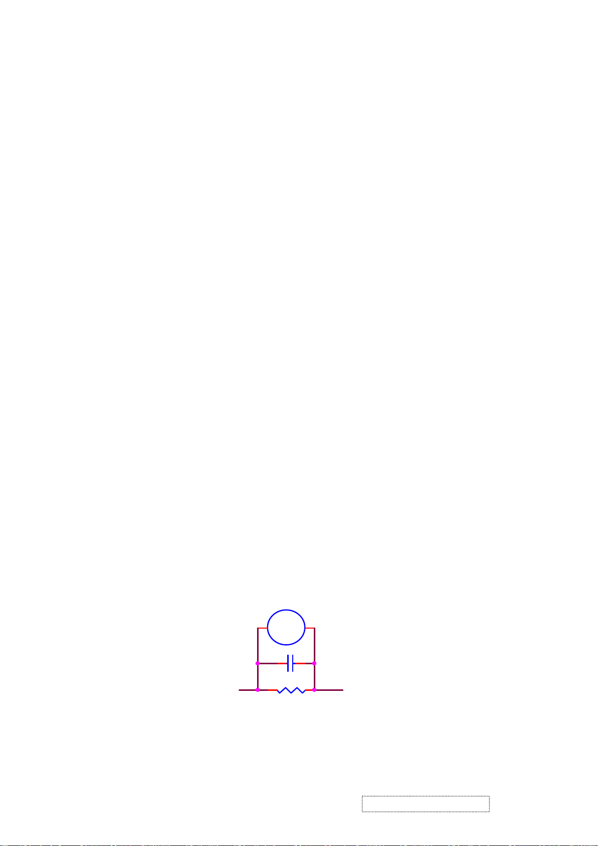
4-1 Plug the AC cord directly into the AC outlet. Do not use an isolation transformer during this check.
4-2 Connect a 1500 ohm , 10 watt resistor , paralleled by a 0.15uF capacitor between each metallic part
and a good earth ground
4-3 Use an AC voltmeter with 1000 ohm / volt or more sensitivity and measure the AC voltage across
the combination 1500 ohm resistor and 0.15uF capacitor.
4-4 Move the resistor connection to each exposed metallic part and measure the voltage.
4-5 Reverse the polarity of the AC plug in the AC outlet and repeat the above measurement.
4-6 Voltage measured must not exceed 1.5 volt RMS, from any exposed metallic part to the ground. A
leakage current tester may be used in the above hot check, in which case any circuit measured must
not exceed 1.0 milliamp. In the case of a measurement exceeding the 1.0 milliamp value, a rework
is required to eliminate the chance of a shock hazard .
AC VOLTMETER
V
0.15u
.
To Metal Parts
1500 10W
Earth Ground
ViewSonic Corporation Confidential
1
-
Do Not Copy VE710b/s-1
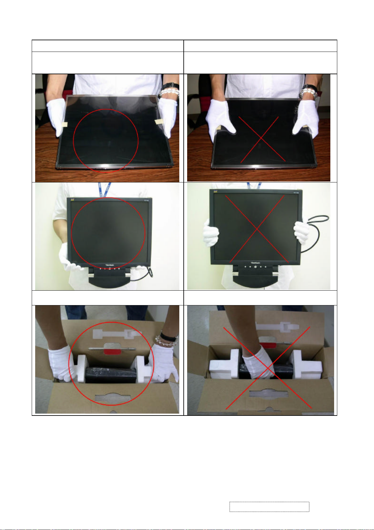
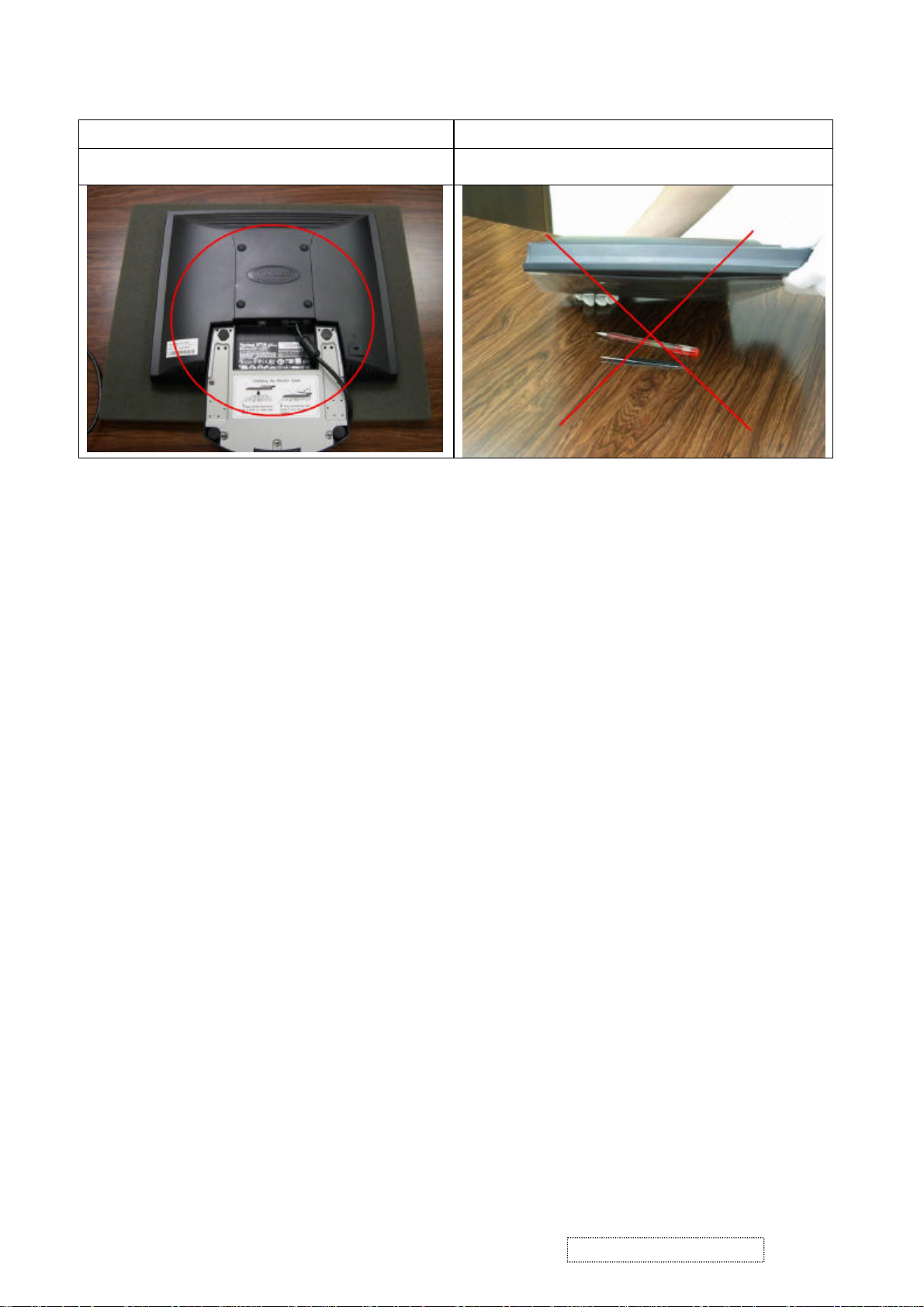
Correct methods : Incorrect Methods :
Only touch the metal-frame of the panel or the front
cover of the monitor .
Do not touch the surface of the polarizer .
Surface of the panel is pressed by fingers & this may
cause “ MURA “
Take out the monitor with cushion Take out the monitor by grasping the LCD panel.
That may cause “ MURA“.
ViewSonic Corporation Confidential
2
-
Do Not Copy VE710b/s-1
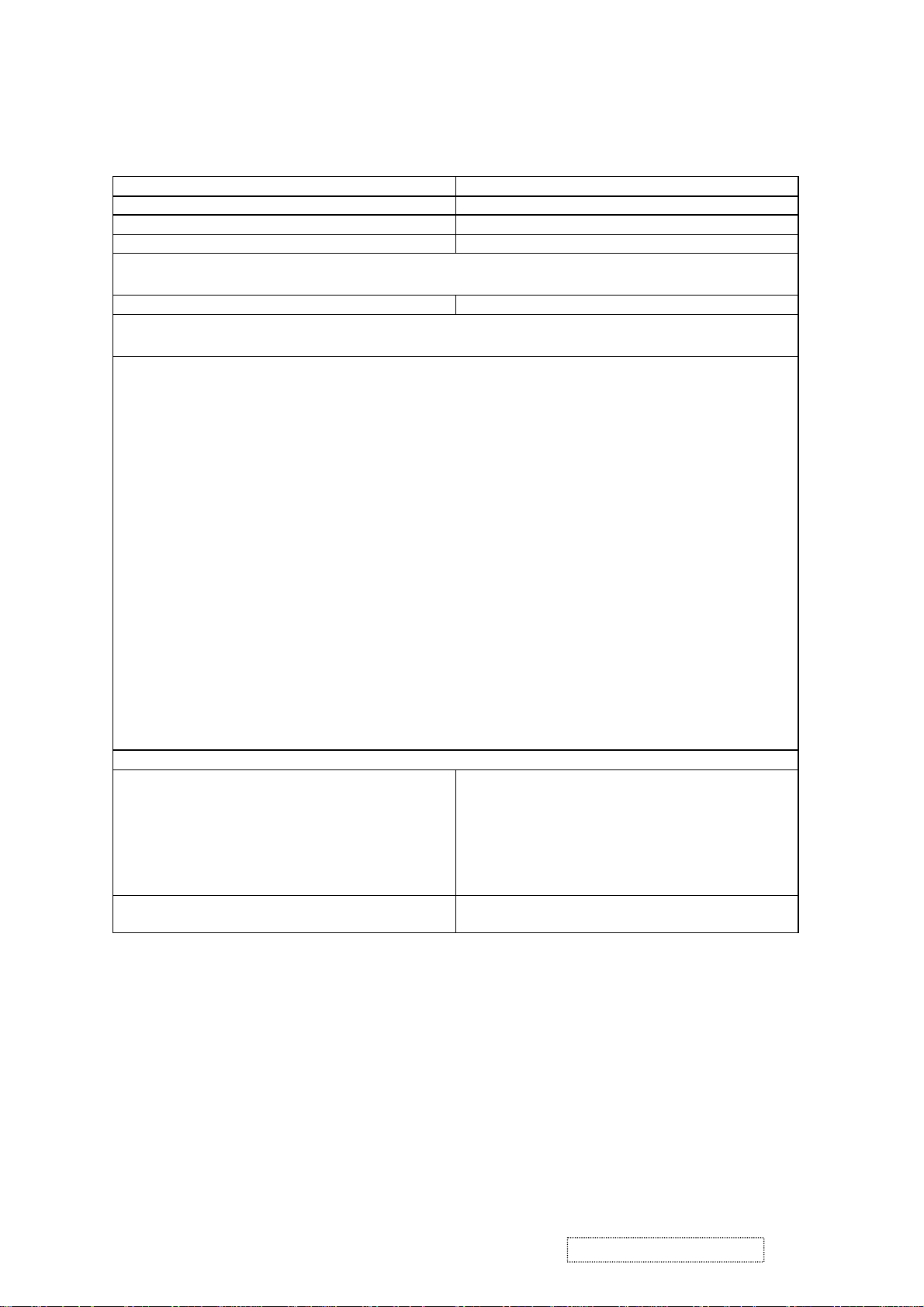
Correct methods : Incorrect Methods :
Place the monitor on a clean & soft foam pad . Place the monitor on foreign objects .
That could scratch the surface of panel
ViewSonic Corporation Confidential
3
-
Do Not Copy VE710b/s-1

2. SPECIFICATION
1. GENERAL REQUIREMENTS
General Specifications
Test Resolution & Frequency 1280 x 1024 @ 60Hz
Test Image Size Full Size
Contrast and Brightness Controls Factory Default: Contrast = 70%, Brightness =
100%
2. SIGNAL INTERFACE
Video Interface
Analog Input Connector DB-15 (Analog)
Video Cable Strain Relief Equal to twice the weight of the monitor for five
minutes.
Video Cable Connector DB-15 Pinout Compliant DDC 2B.
Video Signals Video RGB (Analog)
Video Impedance 75 Ohms (Analog)
Maximum PC Video Signal 950 mV with no damage to monitor
Maximum Mac Video Signal 1250 mV with no damage to monitor
Sync Signals TTL
DDC 1/2B Compliant with Revision 1.3
Video Compatibility Shall be compatible with all PC type computers,
Macintosh computers, and after market video
cards.
Resolution Compatibility 640 x 350, 640 x 480, 720 x 400 (640 x 400), 800 x
600, 832 x 624, 1024 x 768, 1280 x 720, 1280 x
1024
Exclusions Not compatible with interlaced video.
3. POWER
Power Supply
Internal Power Supply Part Number: ADP-40AFB
Input Voltage Range 90 TO 264 VAC
Input Frequency Range 47.5 TO 63 HERTZ
Short Circuit Protection Output can be shorted without damage.
Over Current Protection 4.5 A typical at 12 VDC
Leakage Current 3.5mA (Max) at 254VAC / 60Hz
EFFICIENCY 70 % typical at 115VAC Full Load
Fuse Internal and not user replaceable
Power Dissipation 35 Watts (typ)
Max Input AC Current 1.2 Arms @ 90VAC, 0.8 Arms @180VAC
ViewSonic Corporation Confidential
4
-
Do Not Copy VE710b/s-1
4. ELECTRICAL REQUIREMENTS
Horizontal / Vertical Frequency
Horizontal Frequency 30 – 80 KHZ
Vertical Refresh Rate 50 –85 HZ.
Maximum Pixel Clock 135 MHz
Sync Polarity Independent of sync polarity.
Primary Presets
Primary Preset 1280 x 1024 @ 60Hz
Look up table timing
<<Analog>>
1. 640 x 350 @ 70Hz, 31.5kHz
2. 640 x 480 @ 60Hz, 31.5kHz
3. 640 x 480 @ 67Hz, 35.0kHz
4. 640 x 480 @ 75Hz, 37.5kHz
5. 640 x 480 @ 72Hz, 37.9kHz
6. 640 x 480 @ 85Hz, 43.27kHz
7. 720 x 400 @ 70Hz, 31.5kHz
8. 800 x 600 @ 56Hz, 35.1kHz
9. 800 x 600 @ 60Hz, 37.9kHz
10. 800 x 600 @ 75Hz, 46.9kHz
11. 800 x 600 @ 72Hz, 48.1kHz
12. 800 x 600 @ 85Hz, 53.7kHz
13. 832 x 624 @ 75Hz, 49.7kHz
14. 1024 x 768 @ 60Hz, 48.4kHz
15. 1024 x 768 @ 70Hz, 56.5kHz
16. 1024 x 768 @ 72Hz, 58.1kHz
17. 1024 x 768 @ 75Hz, 60.0kHz
18. 1024 x 768 @ 85Hz, 68.67kHz
19. 1280 x 1024 @ 60Hz, 63.4kHz
20. 1280 x 1024 @ 75Hz, 79.97kHz
21. 1280x720 @ 60Hz, 45kHz (HDTV)
Changing Modes
Maximum Mode Change Blank Time, for
image stability. Note:
1) Excluding “Auto Adjust” time
2) Under DOS mode (640 x 350, 720 x 400 & 640 x
3 seconds (Max)
1 seconds (Typ) for recognized timings
1-2 seconds (Typ) for unrecognized timing
.
400), there is no “Auto Adjust” feature.
3) The monitor needs to do “Auto Adjust” the first
time a new mode is detected.
Mode Change Image The image shall blank while the monitor changes
modes.
ViewSonic Corporation Confidential
5
-
Do Not Copy VE710b/s-1
5. LCD PANEL
Panel Characteristics ( 1
st
source )
Panel Type CPT CLAA170EA03
Type Normally white, TN, OPTICAL COMPENSATION
FILM
Active Size 337.920 (H) x 270.336 (V)
Pixel Arrangement RGB Vertical Stripe
Pixel Pitch 0.264 mm
GLASS TREATMENT Anti Glare
# OF BACKLIGHTS 4 CCFL edge-light (2 top / 2 bottom)
BACKLIGHT LIFE 50,000 Hours (Typ) / 40,000 Hours (Min)
Panel Performance
Luminance –
Condition:
300 cd/m2 (typ after 30 minute warmup)
240 cd/m2 (min after 30 minute warmup)
CT = 6500K, Contrast = Max, Brightness = Max
Brightness Uniformity 75 % Entire Area (minimum)
Contrast Ratio 450:1 (typ), 360:1 (min)
Color Depth 16.2M colors (6 bit panel)
Viewing Angle (Horizontal) 140 deg @ CR>10, 170 deg @ CR>5
VIEWING ANGLE (VERTICAL) 130 deg @ CR>10, 170 deg @ CR>5
Response Time
10%-90% @ Ta=25°C
25 ms (Tr= 9 ms, Tf = 16 ms) (typ)
40 ms (Tr= 15 ms, Tf = 25 ms) (max)
Panel Defects Please see Panel Quality Specifications.
Panel Characteristics ( 2nd source )
Panel Type QDI QD17EL07 REV.03 / GBM GBM170SQ1
Type Normally white, TN, OPTICAL COMPENSATION
FILM
Active Size 337.9 (H) x 270.3 (V)
Pixel Arrangement RGB Vertical Stripe
Pixel Pitch 0.264 mm
GLASS TREATMENT Anti Glare
# OF BACKLIGHTS 4 CCFL edge-light (2 top / 2 bottom)
BACKLIGHT LIFE 50,000 Hours (Typ) / 40,000 Hours (Min)
Panel Performance
Luminance –
Condition:
CT = 6500K, Contrast = Max, Brightness = Max
For QDI :
270 cd/m2 (typ after 30 minute warmup)
222 cd/m2 (min after 30 minute warmup)
For GBM :
300 cd/m2 (typ after 30 minute warmup)
240 cd/m2 (min after 30 minute warmup)
Brightness Uniformity 75 % Entire Area (minimum)
Contrast Ratio 450:1 (typ), 300:1 (min)
Color Depth 16.2M colors (6 bit panel)
Viewing Angle (Horizontal) 150 deg @ CR>10, 160 deg @ CR>5
VIEWING ANGLE (VERTICAL) 125 deg @ CR>10, 145 deg @ CR>5
Response Time
10%-90% @ Ta=25°C
16 ms (Tr= 4 ms, Tf = 12 ms) (typ)
25 ms (Tr= 5 ms, Tf = 20 ms) (max)
Panel Defects Please see Panel Quality Specifications.
ViewSonic Corporation Confidential
6
-
Do Not Copy VE710b/s-1
6. MECHANICAL
Dimensions (Base attached unless otherwise specified)
Width 377.6 mm
Height 374.0 mm
Depth 195.6 mm
Depth (Head Only) 55.0 mm
Monitor Weight 4.1 kg / 9.0 lbs
Packaging Specification
Width 450 mm
Height 522 mm
Depth 135 mm
Gross Weight 5.2 kg (11.45 lb)
# units per Pallet 36/72 (air/sea)
20’/40’ Container Loading, Palletized 720/1728 pieces
Ergonomics
Tilt Up 20 degrees minimum
Tilt Down -5 degrees
Swivel Right 0 degrees
Swivel Left 0 degrees
Height Adjust 0 mm
Pivot 0 degrees (Clockwise)
7. ENVIRONMENTAL
Environmental Conditions
Operating Temperature 0°C to +40°C
Storage Temperature -20°C to +60°C
Operating Relative Humidity 20% to 90% RH Non-Condensing
Storage Relative Humidity 5% to 90% RH Non-Condensing
Operating Altitude 0 to +3,000 meters
Storage Altitude 0 to +12,000 meters
ViewSonic Corporation Confidential
7
-
Do Not Copy VE710b/s-1
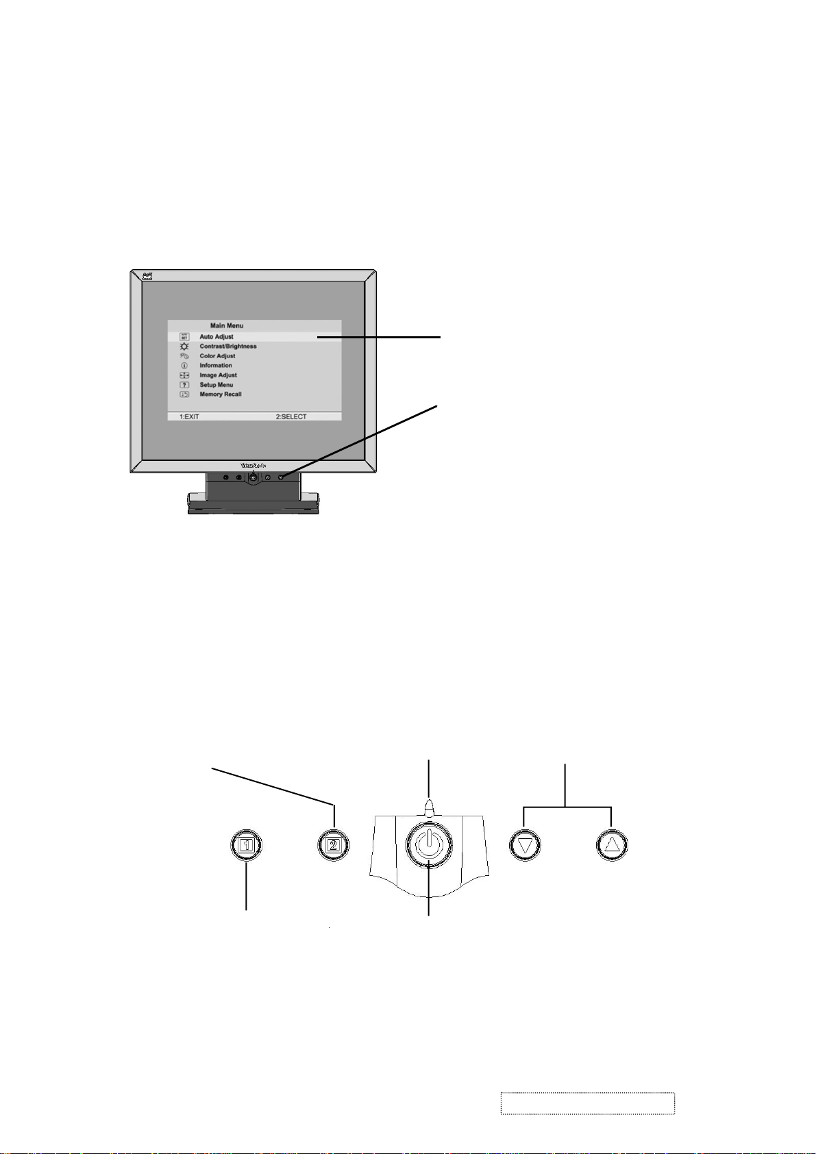
3. Front Panel Function Control Description
Adjusting the Screen Image
Use the buttons on the front control panel to display and adjust the OnView
controls which display on the screen. The OnView controls are explained at the
top of the next page.
Main Menu
With OnView controls
Front Control Panel
shown below in detail
®
Displays the control
screen for the highlighted
control.
Also toggles between two
controls on some
screens.
Also a shortcut to Auto
Image Adjust.
Displays the Main Menu
or exits the control screen
and saves adjustments.
Power light
Green = ON
Orange = Power Saving
Power
On/Off
Scrolls through menu options and
adjusts the displayed control.
Also a shortcut to display the
Contrast adjustment control
screen.
ViewSonic Corporation Confidential
8
-
Do Not Copy VE710b/s-1
Do the following to adjust the screen image:
1
To display the Main Menu, press button [1].
Main Menu
AUTO
SET
?
1:EXIT 2:SELECT
Auto Adjust
Contrast/Brightness
Color Adjust
Information
i
Image Adjust
Setup Menu
Memory Recall
NOTE: All OnView menus and adjustment screens disappear automatically
after about 15 seconds. This time period is adjustable through the Setup
menu and the OSD timeout control described on page 11.
2
To highlight a control you want to adjust, press I or J to scroll up or down
the Main Menu.
3
To select the highlighted control, press button [2]. A control screen appears
like the example shown below.
Contrast
1:EXIT 2: Brightness
4
To adjust the control, press the upIor downJbuttons.
5
To save the adjustments and exit the menu, press button [1] twice.
Thefollowing tips may help you optimizeyour display:
The line at the
bottom of the
screen tells you
what you can do
next: Exit or Select
the control that is
highlighted.
• Adjust your computer's graphic card so that it outputs a video signal 1280 x
1024 @ 60 Hz to the LCD dislay. (Look for instructions on “changing the
refresh rate” in your graphic card's user guide.)
• If necessary, make small adjustments using H. POSITION and V. POSITION
until the screen image is completely visible
. (The black border around the
edge of the screen should barely touch the illuminated “active area” of the
LCD dislay.)
ViewSonic Corporation Confidential
9
-
Do Not Copy VE710b/s-1
Main Menu Controls
Adjust the menu items shown below by using the up Iand down Jbuttons.
Control Explanation
Auto Adjust
automatically sizes, centers, and fine tunes the
video signal to eliminate waviness and distortion.
Press the [2] button to obtain a sharper image.
NOTE
: Auto Adjust works with most common video cards. If
this function does not work on your LCD dislay, then lower the
video refresh rate to 60 Hz and set the resolution to its pre-set
value.
Contrast
adjusts the difference between the image background
(black level) and the foreground (white level).
Brightness
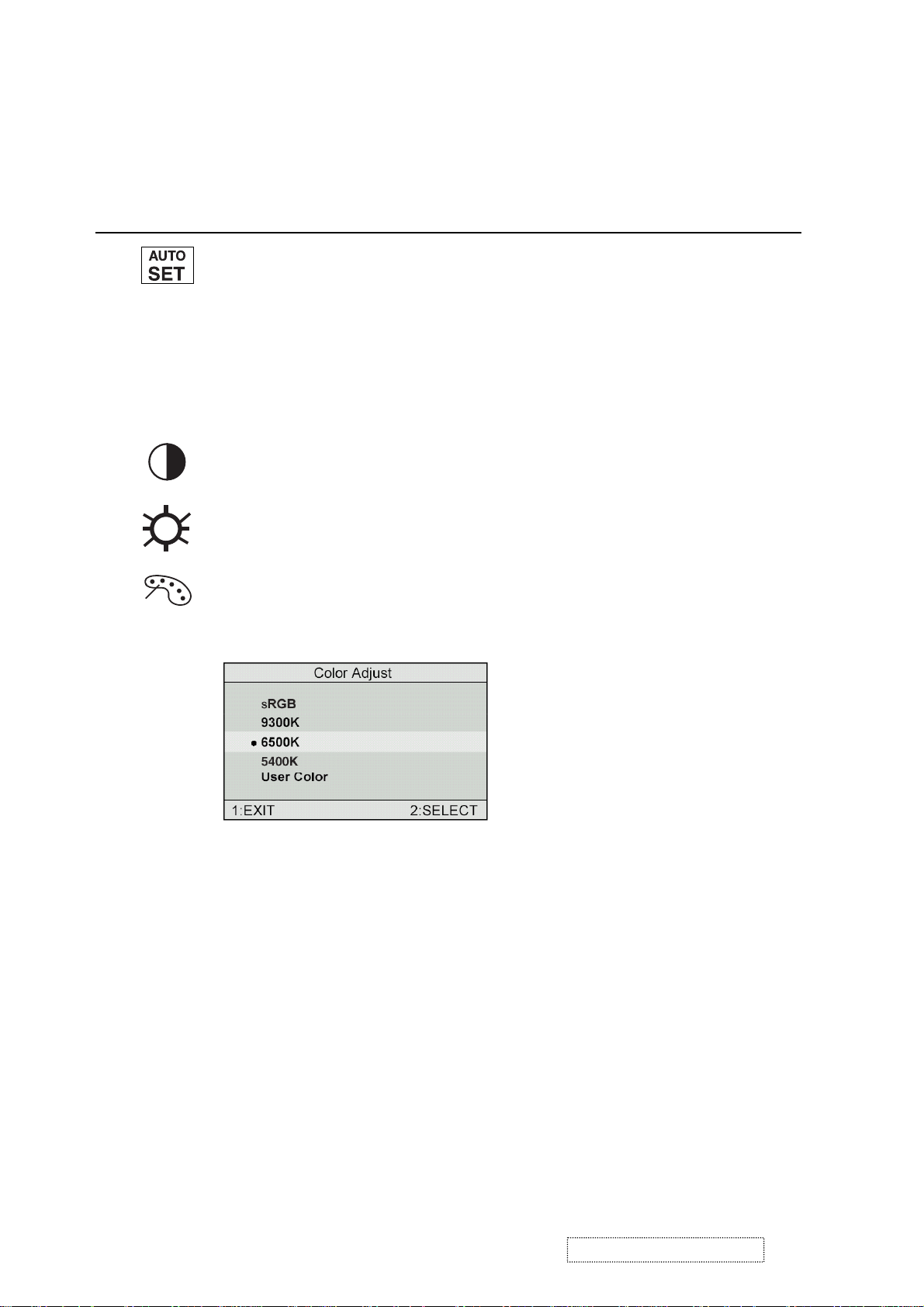
Color Adjust
adjusts background black level of the screen image.
provides several color options: preset color
temperatures and User which allows you to adjust red (R), green
(G), and blue (B). The factory setting for this product is 6500K
(6500 Kelvin).
sRGB
— sRGB is quickly becoming the industry standard for color
management, with support being included in many of the latest
applications. Enabling this setting allows the LCD display to
more accurately display colors the way they were originally
intended. Enabling the sRGB setting will cause the Contrast and
Brightness adjustments to be disabled.
9300K
— Adds blue to the screen image for cooler white (used
in most office settings with fluorescent lighting).
6500K
— Adds red to the screen image for warmer white and
richer red. Default setting.
5400K — Adds green to the screen image for a darker color.
ViewSonic Corporation Confidential
10
-
Do Not Copy VE710b/s-1
Control Explanation
User
— Individual adjustments for red, green, and blue.
1
To select color (R, G or B) press button [2].
2
To adjust selected color, press I or J.
3
When you are finished making all color adjustments, press
button [1] twice.
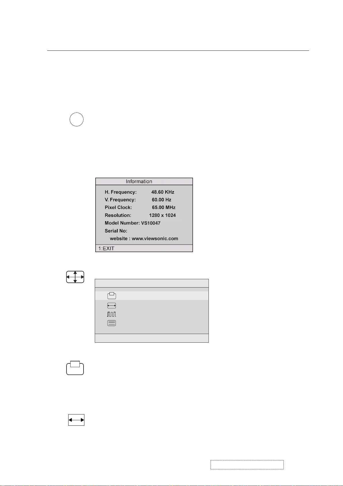
i
Information
coming from the graphics card in your computer. See your
displays the timing mode (video signal input)
graphic card’s user guide for instructions on changing the
resolution and refresh rate (vertical frequency).
VESA 1280 x 1024 @ 60 Hz (recommended) means that the
resolution is 1280 x 1024 and the refresh rate is 60 Hertz.
Image Adjust
Image Adjust
H./V. Position
H. Size
Fine Tune
Sharpness
1:EXIT 2:SELECT
The Image Adjust controls are explained below:
H./V. Position
adjusts horizontal and vertical position of the
screen image. You can toggle between Horizontal and Vertical
by pressing button [2]. Horizontal moves the screen image to
the left or to the right. Vertical moves the screen image up and
down.
H. Size
NOTE:
(Horizontal Size) adjusts the width of the screen image.
Vertical size is automatic with your LCD dislay.
ViewSonic Corporation Confidential
11
-
Do Not Copy VE710b/s-1
Control
Explanation
Fine Tune sharpens focus by aligning the illuminated text and/
or graphic characters.
NOTE: Try the Auto Adjust (see page 9) before using the Fine
Tune control.
?
Sharpness
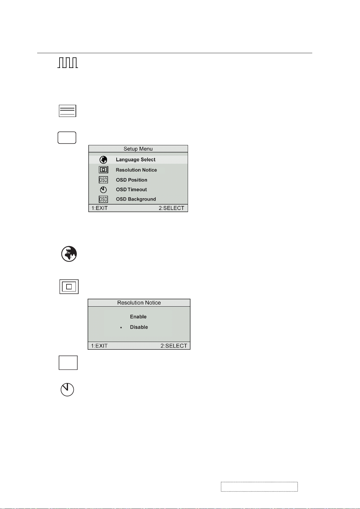
Setup Menu displays the menu shown below.
adjusts the clarity and focus of the screen image.
The Setup Menu controls are explained below.
L
anguage
Select allows you to choose the language used in
the menus and control screens.
OSD
Resolution Notice
OSD Position
advises the optimal resolution to use.
allows you to move the on-screen display menus
and control screens.
OSD Timeout
sets the length of time an on-screen display
screen is displayed. For example, with a “15 second” setting, if
a control is not pushed within 15 seconds, the display screen
disappears.
ViewSonic Corporation Confidential
12
-
Do Not Copy VE710b/s-1
Control Explanation
OSD
OSD Background
allows you to turn the On-Screen display
background on or off. This means that while making adjustments
from the OSD control screens you can also view open software
applications, or the Windows desktop.
Memory Recall
returns adjustments to the original factory
settings if the display is operating in a factory Preset Timing
Mode listed in this user guide.
ViewSonic Corporation Confidential
13
-
Do Not Copy VE710b/s-1
4. Circuit Description
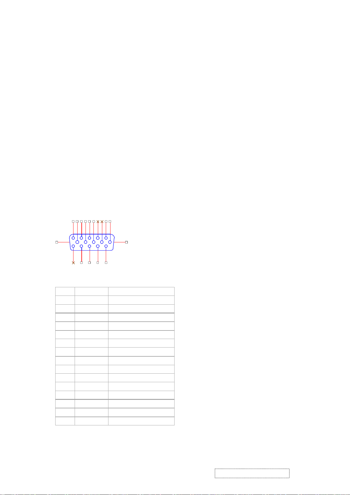
PIN
MNEMONI
SIGNAL
1RVRed Video
2GVGreen Video
3BVBlue Video
4NCNone5GND
Ground(DDC return)
6RGRed GND
7GGGreen GND
8BGBlue GND
9
+5V
+ 5V (for DDC)
10SGSync GND
11NCNone
12
SDA
DDC Data
13HSHorizontal Sync
14VSVertical Sync
15
SCL
DDC Clock
1. Outline
1.1 POWER On/Off , LED, Button"2" , Up arrow- button , Down arrow button , Button"1" , button , Down
arrow button , Button"1" , on the front panel.
1.2 Video signal connector, and AC-IN are located on the back side of the cabinet.
1.3 OSD menu includes the following function;
AUTO IMAGE ADJUST
CONTRAST / BRIGHTNESS
COLOR ADJUST
INFORMATION
MANUAL IMAGE ADJUST
SETUP MENU
MEMORY RECALL
1.4 CONTRAST and BRIGHTNESS can be directly controlled with UP / DN key.
.
2. CONNECTORS
2.1 AC inlet : CEE22 typed connector
2.2 Video signal connector 14P + Mini D-Sub
162738495
16 17
11
12
13
14
CN6
10
DB15HD
15
ViewSonic Corporation Confidential
-
Do Not Copy VE710b/s-1
14
3. ELECTRICAL SPECIFICATIONS
3.1 Standard conditions
Display Area 338 x 270 mm
Video Signal 0.7 Vpp
Contrast 70%
Brightness Max.
Ambient
Input AC
Warming up > 30 min
Display 1280 x 1024
3.2 POWER
3.2.1 Power supply
Input Voltage 90 -240 ~Volts
Power Frequency
Input current
Inrush current 90A(max.) at 230Vac
Power consumption 50Watt
Output Voltage @0-3.0A load 12Vdc
3.2.2 Power Management
State Power Indicator
20 +/- 5 °C
50/ 60 Hz +/-3Hz
<1.5Arms @ 90Vac
<0.75Arms@240Vac
+/-5%
On 45Watt Green
Standby <1Watt Amber
Off <1Watt
3.3 Acceptable timing
If your timing is within following specification, this LCD display can automatically function with a certain
position.
Horizontal: Sync frequency : 30~80 kHz
Vertical: Sync frequency : 50~85Hz(1280x1024,75Hz)
ViewSonic Corporation Confidential
15
-
Do Not Copy VE710b/s-1

3.4 Signal level and input impedance
3.4.1 Video Signal level This LCD display is adjusted at the factory using 0,7 Vp-p Video signal.
3.4.2 Sync Signal level
H/V Separate : TTL level
3.4.3 Input impedance
Video input : 75 ohms
Sync input : > 1 k ohms
4. SIGNAL CABLE : Signal cable with Mini D-Sub 15P connectors at both ends. Length : 1.8 meter.
5. EDID data
Analog EDID
Time: 09:08:54
Date: Wed Sep 04, 2002
______________________________________________________________________
VIEWSONIC CORPORATION
EDID Version # 1, Revision # 3
DDCTest For: VSC VE710s
______________________________________________________________________
0 | 00 FF FF FF FF FF FF 00 5A 63
10 | 18 F5 01 01 01 01 01 0D 01 03
20 | 08 22 1B 78 2E 04 A5 A3 58 4F
30 | 95 24 19 50 54 BF EF 80 81 80
40 | 81 40 71 4F 01 01 01 01 01 01
50 | 01 01 01 01 30 2A 00 98 51 00
60 | 2A 40 30 70 13 00 52 0E 11 00
70 | 00 1E 00 00 00 FF 00 41 33 33
80 | 30 33 30 31 30 30 30 30 31 0A
90 | 00 00 00 FD 00 32 4B 1E 50 0E
100 | 00 0A 20 20 20 20 20 20 00 00
110 | 00 FC 00 56 45 37 31 30 73 0A
120 | 20 20 20 20 20 20 00 98
____________________________________________________________________
(0
8-09) ID Manufacturer Name = VSC
0-11) Product ID Code (Non-Alphanumerical) = F518
(1
(1
2-15) Last 5 Digits of Serial Number = NOT SPECIFIED
(16) Week of Manufacture = 01
(17) Year of Manufacture = 2003
(1
0-17) Complete Serial Number = NOT SPECIFIED
(18) EDID Structure Version Number = 1
(19) EDID Structure Revision Number = 3
(20) VIDEO INPUT DEFINITION : =
Separate Sync, Analog signal, 0.700V/0.300V (1.000 Vp-p)
ViewSonic Corporation Confidential
16
-
Do Not Copy VE710b/s-1

(21) Maximum Horizontal Image Size= 340mm
(22) Maximum Vertical Image Size = 270mm
(23) Display Gamma = 2.20
(24) DPMS Supported Feature = Active Off.
Display type = RGB color display
(25-34) CHROMA INFO:
Red x = 0.637 Green x = 0.310 Blue x = 0.143 White x = 0.313
Red y = 0.344 Green y = 0.586 Blue y = 0.100 White y = 0.329
(35) ESTABLISHED TIMING I:
720 x 400 @ 70Hz (VGA, IBM)
640 x 480 @ 60Hz (MAC II, Apple)
640 x 480 @ 67Hz (VESA)
640 x 480 @ 72Hz (VESA)
640 x 480 @ 75Hz (VESA)
800 x 600 @ 56Hz (VESA)
800 x 600 @ 60Hz (VESA)
(36) ESTABLISHED TIMING II:
800 x 600 @ 72Hz (VESA)
800 x 600 @ 75Hz (VESA)
832 x 624 @ 75Hz (MAC II, Apple)
1024 x 768 @ 60Hz (VESA)
1024 x 768 @ 70Hz (VESA)
1024 x 768 @ 75Hz (VESA)
1280 x 1024 @ 75Hz (VESA)
(37) Manufacturer's Reserved Timing:
1152 x 870 @ 75Hz (MAC II, Apple)
(38-53) Standard Timing Identification:
#1: 1280 x 1024 @60Hz
#2: 1280 X 960 @60HZ
#3: 1152 X 864 @75HZ
#4: (44) not specified
#5: (46) not specified
#6: (48) not specified
#7: (50) not specified
#8: (52) not specified
(54-71) Detail Timing Description #1: 1280x1024 Pixel Clock=108.0MHz
Horizontal Image Size=338mm Vertical Image Size=270mm
Refresh Mode: Non-Interlaced Normal display, no stereo
ViewSonic Corporation Confidential
17
-
Do Not Copy VE710b/s-1

Horizontal Image Size=338mm Vertical Image Size=270mm
Refresh Mode: Non-Interlaced Normal display, no stereo
HORIZONTAL:
Active Time = 1280 pixels Blanking Time = 408 pixels
Sync Offset = 48 pixels Sync Pulse Width = 112 pixels
Border = 1 pixels Frequency = 64.0 kHz
VERTICAL:
Active Time = 1024 lines Blanking Time = 42 lines
Sync Offset = 1 lines Sync Pulse Width = 3 lines
Border = 0 lines Frequency = 60.0 Hz
Sync configuration: Digital separate, V(+), H(+)
(72-89) Monitor Description:
--------------------------------------------------------------------------------
Monitor S/N: A33030100001
(90-107) Monitor Description:
--------------------------------------------------------------------------------
Monitor Range Limits:
Vertical Frequency (min) = 50Hz
Vertical Frequency (max) = 75Hz
Horizontal Frequency (min) = 30Hz
Horizontal Frequency (max) = 82Hz
Maximum Supported Pixel Clock = 140MHz
SECONDARY GTF - NOT SUPPORTED
(108-125) Monitor Description:
------------------------------------------------------------------------------- Monitor Name: VE710s
(127) Checksum OK
6. THEORY OF OPERATION
This section describes the function of the LCD monitor per functional block.
This monitor includes MB board, power board and button board.
6.1 MB BOARD
The MB board is a two-layer, single-landed design with ground and internal planes provided. DC power from the
power board enter the board through a 6P connector. Other connector on the board is for button board .The VGA
cable is a signal cable that contains video signal, sync signal and DDC signal from PC VGA adapter. This system
board consists of 4 functional areas : flat panel controller, MCU with flash ROM , power regulator .
6.1.1 Flat panel controller… MST8111A (U3)
The heart of the system board is MStar MST8111A. The MST8111A is a graphics processing IC for LCD
monitor. It provides all key IC functions required for LCD panel. On-chip functions include a high-speed
triple-ADC , PLL, high scaling engine, OSD controller.
ViewSonic Corporation Confidential
18
-
Do Not Copy VE710b/s-1
a) Clock Generation :
Crystal Input Clock (TCLK and XTAL). This is the input pair to an internal crystal oscillator and
corresponding logic. A 14.318 MHz crystal is recommended.
b) Analog to Digital Converter:
The MST8111A chip has three ADC's (analog-to-digital converters), one for each color (red, green and
blue) .The analog RGB signals are connected to MST8111A as described
below
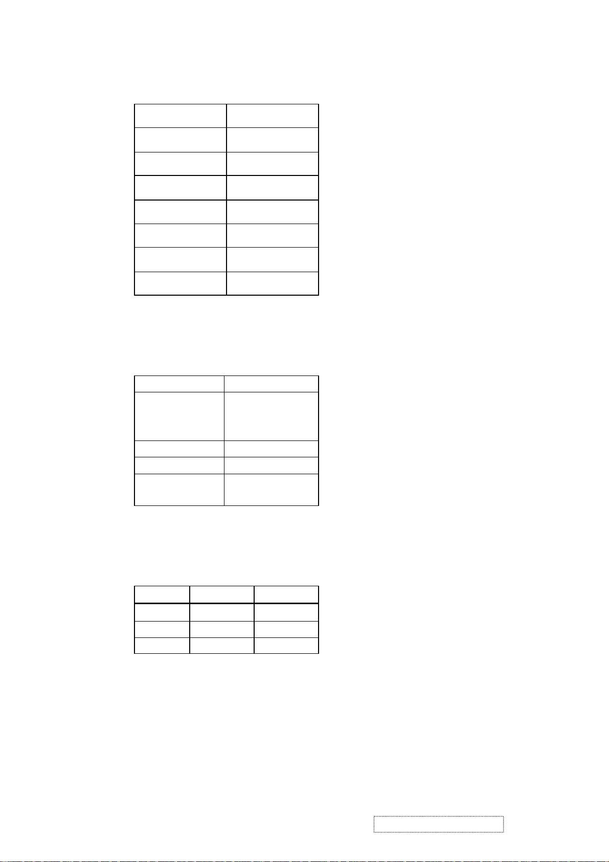
Pin Name Pin Number
Red + 63
Red - 62
Green + 60
Green - 59
Blue + 58
Blue - 57
c) OSD : The MST8111A has a fully programmable ,high-quality OSD controller. The on-chip static
RAM(4096 words by 24 bits) stores the cell map and the cell definitions.
d) MTV312 Micro controller: The MTV312 micro controller(MCU) serves as the system micro controller. It’s
programs the MST8111A and manages other devices in the system such as the keypad, the backlight, LED,
audio and non-volatile RAM. using general purpose input/output (GPIO) pins.
Pin number Pin Name Pin Number Usage
21 P1.3 Key / Power on ,off
13 P3.4 NV_RAM (U4) SDA
14 P3.5 NV_RAM (U4) SCL
25 P1.7 Key_down
9 P6.3 Key_right
24 P1.6 Key_up
16 P6.2 Key_left
37 P4.1 Key_mute
34 P5.6 VGA connector
23 P1.5 Key_select
42 P5.3 LED_red
41 P5.4 LED_green
32 P6.6 LCD panel power1 on / off control
3 P5.0 LCD panel power2 on / off control
36 P4.0 Backlight on / off control
e) Panel Power Sequencing ( VDDCTRL1, 2) ( Pin 32, 3) : The MTV312 has two dedicated outputs
VDDCTRL1 and 2 ( Pin32 and Pin3) to control LCD power sequencing once data and control signals
are stable.
f) Panel interface (Pin 1~25, Pin75~128) : The MTV312 driver interface is highly programmable. It supports
dual bus / dual port for SXGA drivers.
ViewSonic Corporation Confidential
19
-
Do Not Copy VE710b/s-1
 Loading...