

ViewSonic VE702m,VS10535 Service manual
Service Manual
ViewSonic VE702m-1
Model No. VS10535
17” Color TFT LCD Display
ViewSonic
(VE702m_SM_939 Rev. 1a Jan. 2005)
381 Brea Canyon Road, Walnut, California 91789 USA - (800) 888-8583
Copyright
Copyright
2005 ViewSonic Corporation. All rights reserved. No part of this publication may be
¤
reproduced, transmitted, transcribed, stored in a retrieval system, or translated into any language or
computer language, in any form or by any means, electronic, mechanical, magnetic, optical, chemical,
manual or otherwise, without the prior written permission of ViewSonic Corporation.
Disclaimer
ViewSonic makes no representations or warranties, either expressed or implied, with respect to the
contents hereof and specifically disclaims any warranty of merchantability or fitness for any particular
purpose. Further, ViewSonic reserves the right to revise this publication and to make changes from time
to time in the contents hereof without obligation of ViewSonic to notify any person of such revision or
changes.
Trademarks
Optiquest is a registered trademark of ViewSonic Corporation.
ViewSonic is a registered trademark of ViewSonic Corporation.
All other trademarks used within this document are the property of their respective owners.
1a
03/01/05
Revision History
Documents Number
DCN Number ECR Number
4866
Description of Changes EditorRevision SM Editing Date
Initial Release
A. Lu
ViewSonic Corporation Confidential
i
-
Do Not Copy VE702m

TABLE OF CONTENTS
1. Precautions and Safety Notices
2. Specification
3. Front Panel Function Control Description
4. Circuit Description
5. Adjusting Procedure
6. Trouble Shooting Flow Chart
7. Recommended Spare Parts List
8. Exploded Diagram And Spare Parts List
9. Block Diagram
10. Schematic Diagrams
11. PCB Layout Diagrams
1
5
9
14
17
41
46
51
54
55
64
ViewSonic Corporation Confidential
ii
-
Do Not Copy VE702m

1. Precautions and Safety Notices
1. Appropriate Operation
(1) Turn off the product before cleaning.
(2) Use only a dry soft cloth when cleaning the LCD panel surface.
(3) Use a soft cloth soaked with mild detergent to clean the display housing.
(4) Use only high quality and safety approved AC/DC power cord.
(5) Disconnect the power plug from AC outlet if the product is not used for a long period of time.
(6) If smoke, abnormal noise, or strange odor is present, immediately switch the LCD display off.
(7) Do not touch the LCD panel surface with sharp or hard objects.
(8) Do not place heavy objects on the LCD display, video cable, or power cord.
(9) Do not use abrasive cleaners, waxes or solvents for your cleaning.
(10) Do not operate the product under the following conditions:
- Extremely hot, cold or humid environment.
- Areas susceptible to excessive dust and dirt.
- Near any appliance generating a strong magnetic field.
- Place in direct sunlight.
2. Caution
No modification of any circuit should be attempted. Service work should only be performed after you are thoroughly familiar
with all of the following safety checks and servicing guidelines.
3. Safety Check
Care should be taken while servicing this LCD display. Because of the high voltage used in the inverter circuit, the voltage is
exposed in such areas as the associated transformer circuits.
4. LCD Module Handling Precautions
4.1 Handling Precautions
(1) Since front polarizer is easily damaged, pay attention not to scratch it.
(2) Be sure to turn off power supply when inserting or disconnecting from input connector.
(3) Wipe off water drop immediately. Long contact with water may cause discoloration or spots.
(4) When the panel surface is soiled, wipe it with absorbent cotton or other soft cloth.
(5) Since the panel is made of glass, it may break or crack if dropped or bumped on hard surface.
(6) Since CMOS LSI is used in this module, take care of static electricity and insure human earth when handling.
(7) Do not open nor modify the Module Assembly.
(8) Do not press the reflector sheet at the back of the module to any directions.
(9) In case if a Module has to be put back into the packing container slot after once it was taken out from the
container, do not press the center of the CCFL Reflector edge. Instead, press at the far ends of the CFL
Reflector edge softly. Otherwise the TFT Module may be damaged.
(10) At the insertion or removal of the Signal Interface Connector, be sure not to rotate nor tilt the Interface
Connector of the TFT Module.
ViewSonic Corporation Confidential
1
-
Do Not Copy VE702m

(11) After installation of the TFT Module into an enclosure (LCD monitor housing, for example), do not twist nor
bend the TFT Module even momentary. At designing the enclosure, it should be taken into consideration that
no bending/twisting forces are applied to the TFT Module from outside. Otherwise the TFT Module may be
damaged.
(12) Cold cathode fluorescent lamp in LCD contains a small amount of mercury. Please follow local ordinances or
regulations for disposal.
(13) Small amount of materials having no flammability grade is used in the LCD module. The LCD module should
be supplied by power complied with requirements of Limited Power Source (IEC60950 or UL1950), or be
applied exemption.
(14) The LCD module is designed so that the CFL in it is supplied by Limited Current Circuit (IEC60950 or
UL1950). Do not connect the CFL in Hazardous Voltage Circuit.
ViewSonic Corporation Confidential
2
-
Do Not Copy VE702m

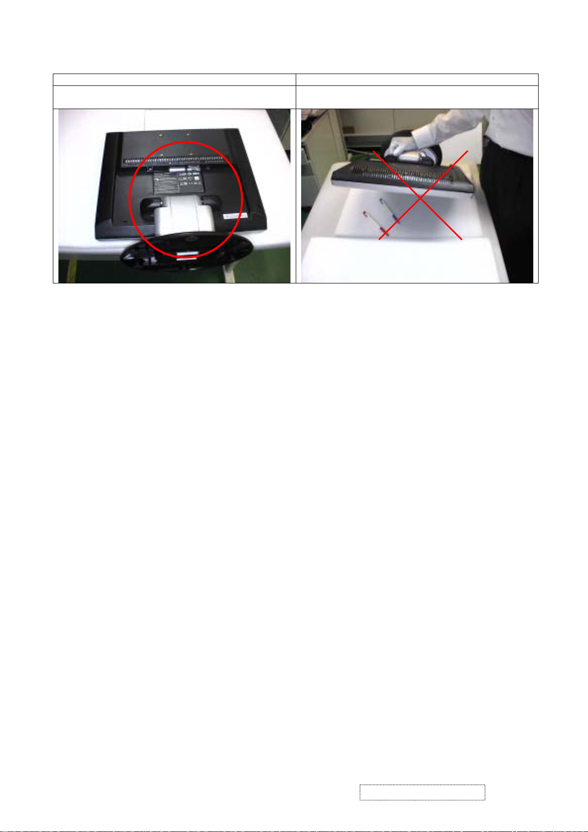
Correct methods : Incorrect Methods :
Only touch the metal-frame of the panel or the front
cover of the monitor.
Do not touch the surface of the polarize .
Surface of the panel is pressed by fingers & this may
cause “ MURA “
Take out the monitor with cushion Take out the monitor by grasping the LCD panel.
That may cause “ MURA“.
ViewSonic Corporation Confidential
3
-
Do Not Copy VE702m
Correct Methods : Incorrect Methods :
Place the monitor on a clean & soft foam pad . Place the monitor on foreign objects .
That could scratch the surface of panel
ViewSonic Corporation Confidential
4
-
Do Not Copy VE702m
2. Specification
2-1 General Descriptions
Item Specification Unit
Active Area 337.9 (H) x 270.34 (V) (17.0” diago nal) mm
Driver Element a-si TFT Active Matrix Pixel Number 1280 x R.G.B. x 1024 pixel
Pixel Pitch 0.264 (H) x 0.264 (V) mm
Pixel Arrangement RGB V ertical Stripe -
LCD panel
Graphic
Performance
Display Color 16.2M color
Tran missive Mode Normally White Viewing Angle (H / V) 160 / 120 degree
Brightness 350 cd/m
2
Contrast Ratio 350 LC Response Time (Tr+Tf) 14 (Tr: 4 + Tf: 10) msec
Separate Sync. TTL Level Horizontal Sync. Positive / Negative Vertical Sync. Positive / Negative Input Connector D-Sub mini 15 pins Auto Adjust Clock, Phase, H Position & V Position Screen Scaling VGA/SVGA/XGA/SXGA Full Screen Display Power Management VESA DPMS , ENERGY STAR® Compliance Color Adjustment User, 6500K, 7500K & 9300K OSD Language English, French, German, Spanish, Italian, Japanese,
Traditional Chinese, Simplified Chinese,
-
Russian, Korean,
Power Input AC100~240 (Worldwide) V
Power source
Power Output 19VDC Operation Mode 51 W
Power consumption
Power Saving Mode 3 W
Tilt angle Upward / Downward 20 / 0 degree
Dimension, weight 386.8(W) x 402.45(H) x 213(D), 3.36 mm,
Physical
DCC
Plug & Play
Front key
DDC 2B Compliance -
6keys
Picture Mode: 370
Function
Turbo (Brightness Switch)
Text Mode: 200
Economy Mode: 140
Speaker & Audio (Optional) *
1W*2
ViewSonic Corporation Confidential
5
kg
cd/m
-
Do Not Copy VE702m
-
2
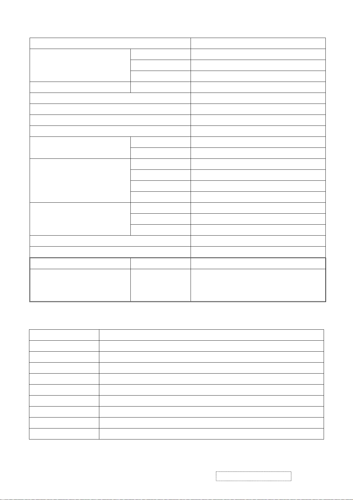
2-2 Electrical Specifications
Item Description
Input System RGB Separate
Video Signal
Signal Level Analog RGB (0.7V
Input Impedance
75Ω
P-P
)
Synchronization Signal Input System Signal Level Separate Sync: TTL
Compliant T imi ng See Appendi x 1.
Input Connector 15 pins mini D-Sub
Video Frequency Bandwidth 135 MHz dot clock
Audio (Optional) d=3.5mm stereo mini jack, 1W/ch
Horizontal Sync. 30 ~ 82 kHz
Synchronization Frequency
Vertical Sync. 56 ~ 76 Hz
Input Voltage AC 100~240V (Worldwide)
Frequency 50 / 60Hz
Power Supply
Power Consumption 51 W (max)
Power Management 3W (max)
Lamp Type Cold Cathode Fluorescent Lamp
Backlight
Lamp Quantity 4pcs
Lamp Life Time 40,000 Hrs (min)
Plug & Play VESA DDC 2B Compliance
Power Management VESA DPMS , ENERGY STAR® Compliance
Power Management Status Power Consumption Screen Recovery Time
Stand-by
Suspend
3W or less Within 3 sec
Active-off
Optical Characteristics
2-3
Temperature
Humidity
AC input voltage
Brightness Maximum with OSD setting
Contrast Middle with OSD setting
Resolution setting 1280 x 1024 @60HZ
Color temperature With OSD setting
Measuring instrument Topcon luminance colorimeter BM-5A or equivalent
Others Before measuring, “Auto Config” & “Auto Balance” must be done in advance
Item Condition
Normal room temperature (25±2℃)
50±10%
100V±2V, 120±2V, 60Hz / 240±2V, 50Hz
ViewSonic Corporation Confidential
6
-
Do Not Copy VE702m
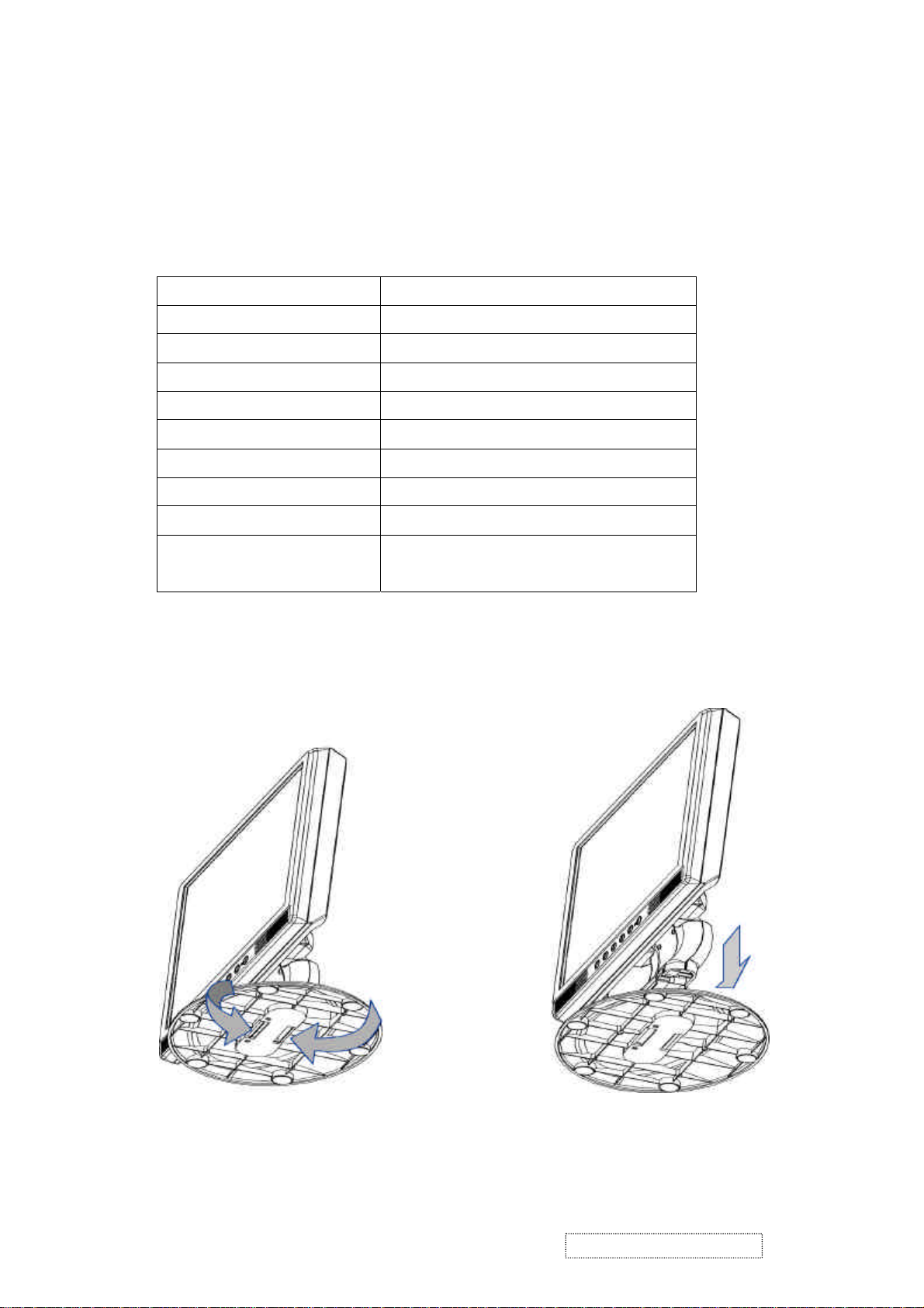
2-4 Accessories
z Power Cable: 1.8m
Rating: 10A, 250V
z Signal Cable: D-sub mini 15pin, 1.8m
z Audio Cable (Optional): 1.8m
Jacket: OD 3.0mm
z AC-DC Adapter:
Supplier (Model No.) ASIAN / DA-60F19-AA
Input Voltage 100 ~ 240VAC
Input frequency 50Hz / 60Hz
Input Current 1600mA (max)
Output Voltage
Output Current 3160mA
Output Power 60 W (19V / 3.16A)
Efficiency AC input 115VAC 80% (min)
Inrush Current
(Cold Start at 25℃, Full Load)
z Quick start guide.
z User Manual CD-ROM.
Stand-bottom to be set by user:
Insulation resistance: 10MΩ/Min. 300V
DC
Item Description
19VDC±5%
120A Max. / 120V
240A Max./ 240V
AC
/ 50Hz
AC
/ 60Hz
ViewSonic Corporation Confidential
7
-
Do Not Copy VE702m
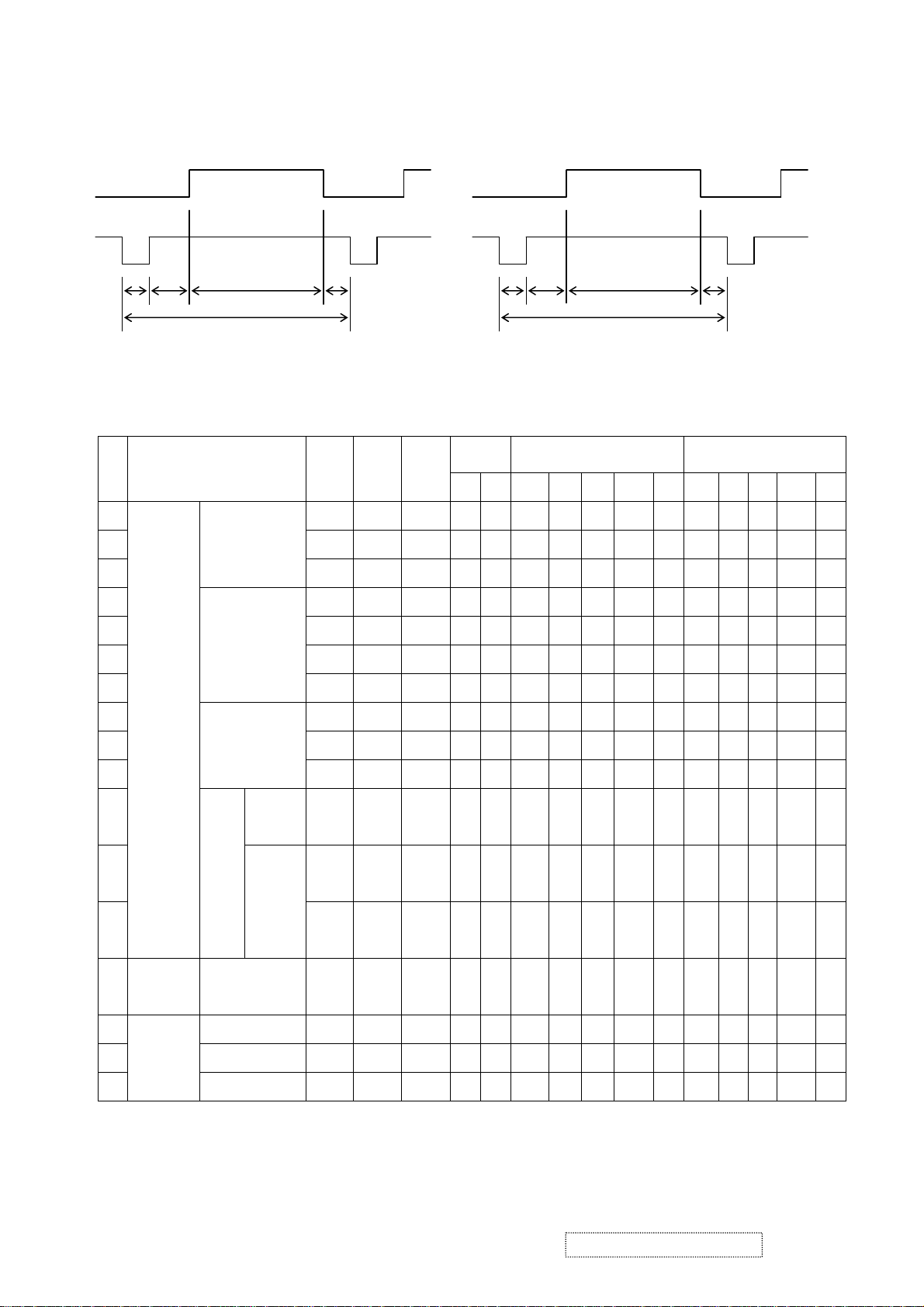
2-5 Compliant Timing
Video
Sync
< Horizontal > <Vertical >
H-parameters
C B
DE
A
A: Total period
B: Sync. width
C: Back porch
D: Active video
E: Front porch
R PQ
O
S
Sync
polarity
Horizontal (dot) Vertical (line) Ite
H V A B C D E O P Q R S
m
Video Mode
fH
(kHz)
fV
(Hz)
Dot
clock
(MHz)
1 31.469 59.940 25.175 N N 800 96 48 640 16 526 2 33 480 11
2 37.861 72.809 31.500 N N 832 40 128 640 24 520 3 28 480 9
3
VGA 640x480
37.500 75.000 31.500 N N 840 64 120 640 16 500 3 16 480 1
V-parameters
O: Total period
P: Sync. width
Q: Back porch
R: Active video
S: Front porch
4 35.156 56.250 36.000 P P 1024 72 128 800 24 625 2 22 600 1
5 37.879 60.317 40.000 P P 1056 128 88 800 40 628 4 23 600 1
SVGA 800x600
6 48.077 72.188 50.000 P P 1040 120 64 800 56 666 6 23 600 37
7
46.875 75.000 49.500 P P 1056 80 160 800 16 625 3 21 600 1
8 48.363 60.004 65.000 N N 1344 136 160 1024 24 806 6 29 768 3
VESA
9 56.476 70.069 75.000 N N 1328 136 144 1024 24 806 6 29 768 3
10
11
12 63.981 60.020
13
XGA 1024x768
1152x86
4
SXG
A
1280x10
24
60.023 75.029 78.750 P P 1312 96 176 1024 16 800 3 28 768 1
108.00
67.500 75.000
P P 1600 128 256 1152 64 900 3 32 864 1
0
79.976 75.025
108.00
P P 1688 112 248 1280 48
0
135.00
P P 1688 144 248 1280 16
0
106
3 38 1024 1
6
106
3 38 1024 1
6
VGA
14
720x400 31.469 70.087 28.322 N P 900 108 45 720 27 449 2 35 400 12
TEXT
15 640x480 35.000 66.667 30.240 N N 864 64 96 640 64 525 3 39 480 3
Macintosh
16 832x624 49.725 74.500 57.283 N N 1152 64 224 832 32 667 3 39 624 1
17
1024x768 60.150 74.720 80.000 N N 1330 96 168 1024 42 805 3 31 768 3
ViewSonic Corporation Confidential
8
-
Do Not Copy VE702m
3. Front Panel Function Control Description
Auto Adjust
Though your computer system can identify the new LCD monitor system, the Auto Adjust
function can be as to enhance the display. To enter adjust mode, please refer to “OSD
Control”.
Turn the computer and LCD monitor on.
Press ‘Auto’ button to start Auto Adjust.
The LCD monitor will start the Auto Adjust process automatically for 10 consecutive
seconds, where you will notice the image change as the Auto Adjust is working.
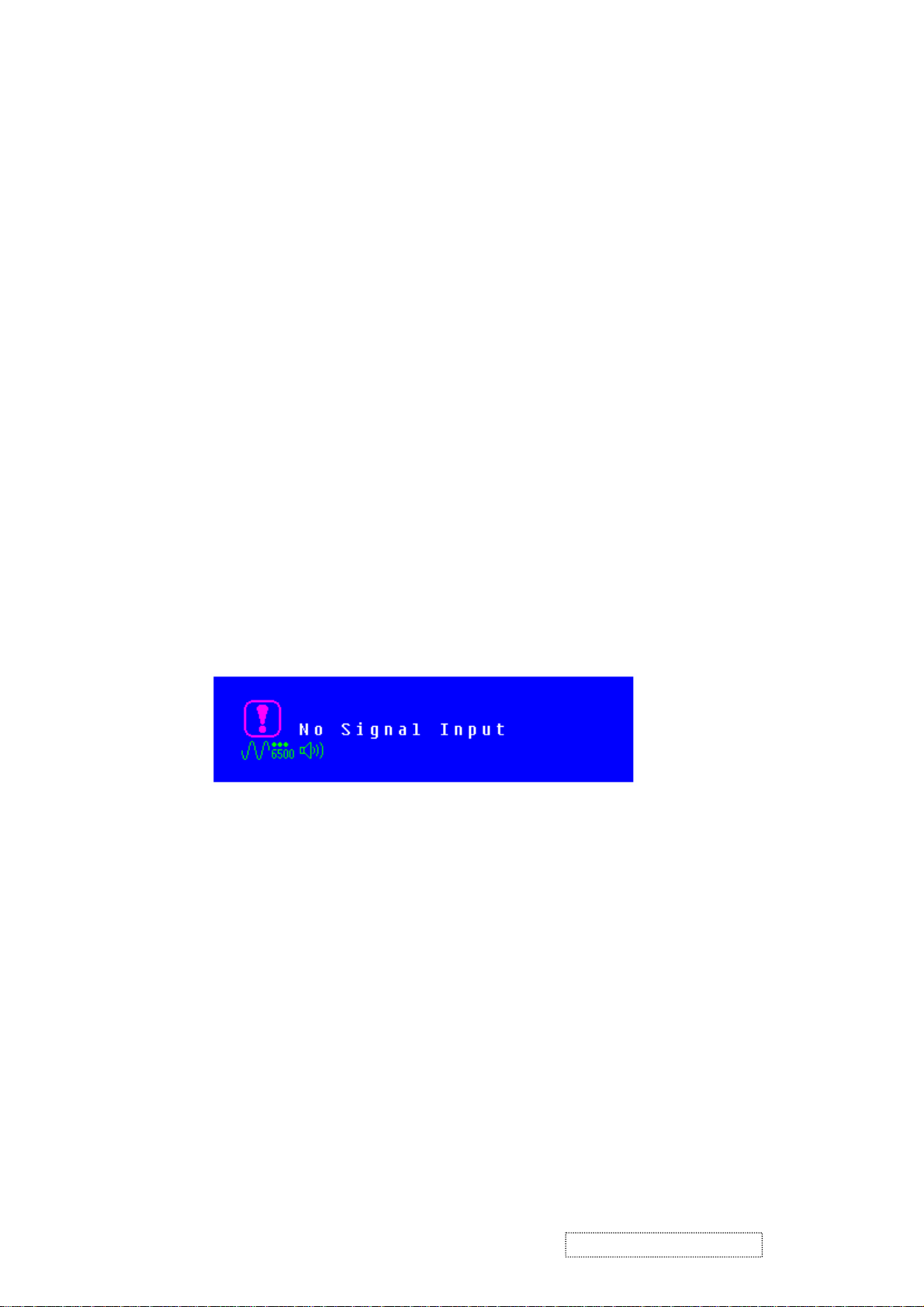
Self Test Function
Check (STFC):
Your LCD monitor provides a STFC function, through which you can check whether
the LCD monitor functions are working properly.
If your LCD monitor is properly connected, but there is no image showing and the
indicator light keeps orange, please follow the steps below to start STFC.
Shutdown computer and LCD monitor.
Unplug the signal connector from the back of computer.
Turn the LCD monitor on.
If the image connector is disconnected or damaged, the image shown on following
figure will also appear during normal operation.
Turn off the LCD monitor and reconnect signal cable, and then turn the
computer and LCD monitor on.
If the LED of the LCD monitor is an orange color after completing the steps above,
please check your VGA card and computer system. Your monitor should be
operating properly.
ViewSonic Corporation Confidential
9
-
Do Not Copy VE702m
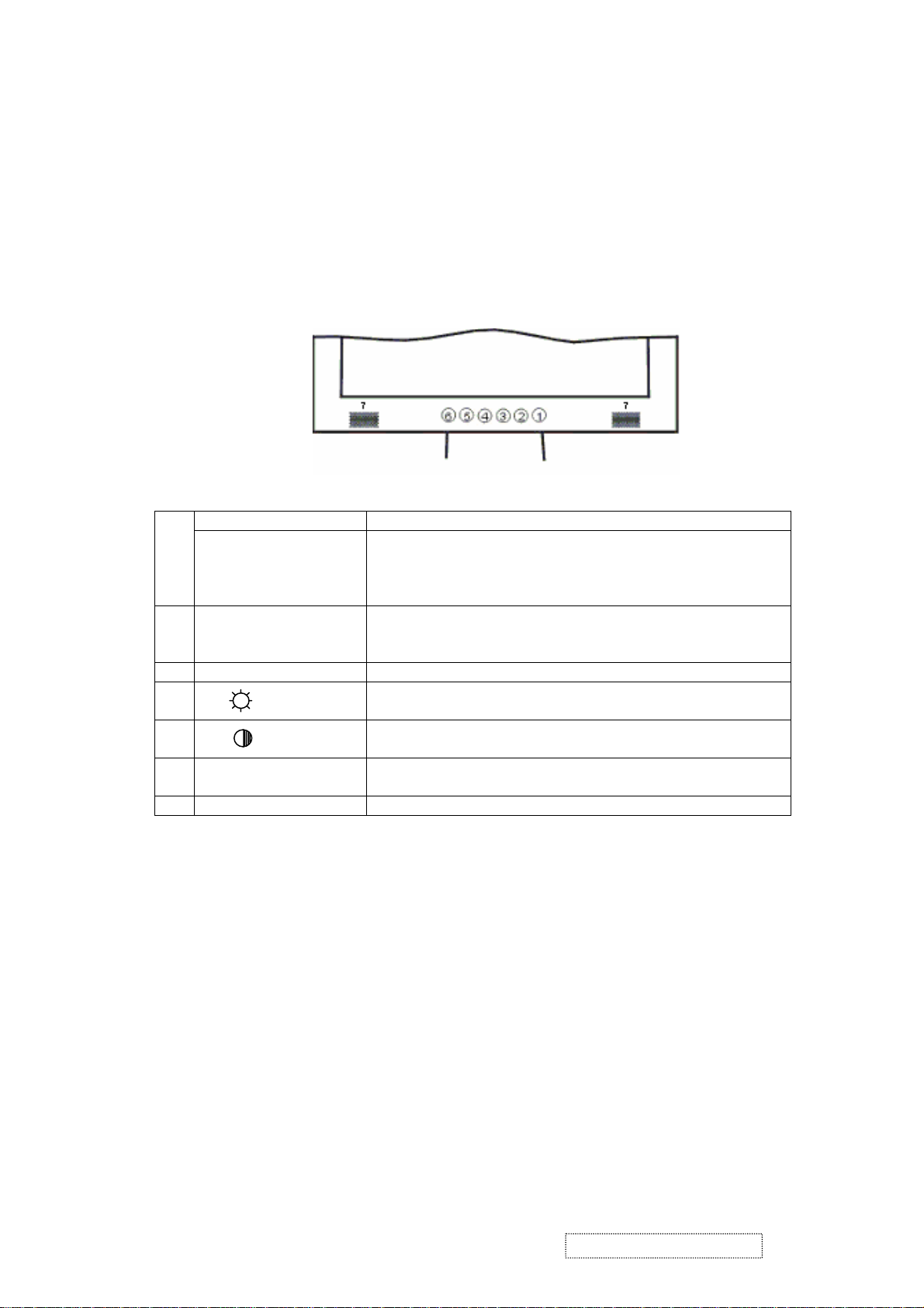
OSD Control
Keypad Button
Definition
Thanks to the user-friendly design of OSD (On Screen Display), you can adjust your
monitor by the keypads in the front of the monitor.
Power Switch Power On/Off 1
LED Power Indicator
Green: Normal
Orange: Power Saving
Off: Power Off
2 Auto / Exit Automatically optimize positions, phase & clock when OSD
is not shown
Exit the OSD menu when OSD is shown
3 Turbo Quick brightness switching
ѡ/
4
5 ʊ/ Adjustment when OSD is shown
6 Menu Enter OSD
7 Speaker
Selection or adjustment when OSD is shown
Quick brightness adjustment
Quick contrast adjustment
Access sub-menu & selection
ViewSonic Corporation Confidential
10
-
Do Not Copy VE702m
Operate Explanation
ting
Your LCD has been adjusted to its optimal status before shipment. You can also adjust
the image in accordance with the following illustrations and steps.
Press the “Menu” button to start the OSD feature.
Click the “+” or “-“ button to select the function to be adjusted.
Click the “Menu” button to access into the function to be adjusted.
Click the “+” or “-“ button to change the current setting of the function.
To exit the OSD menu or go back to the previous action by clicking the “Auto/Exit”
button. It will save the change automatically.
To repeat above steps for changing the setting of other functions.
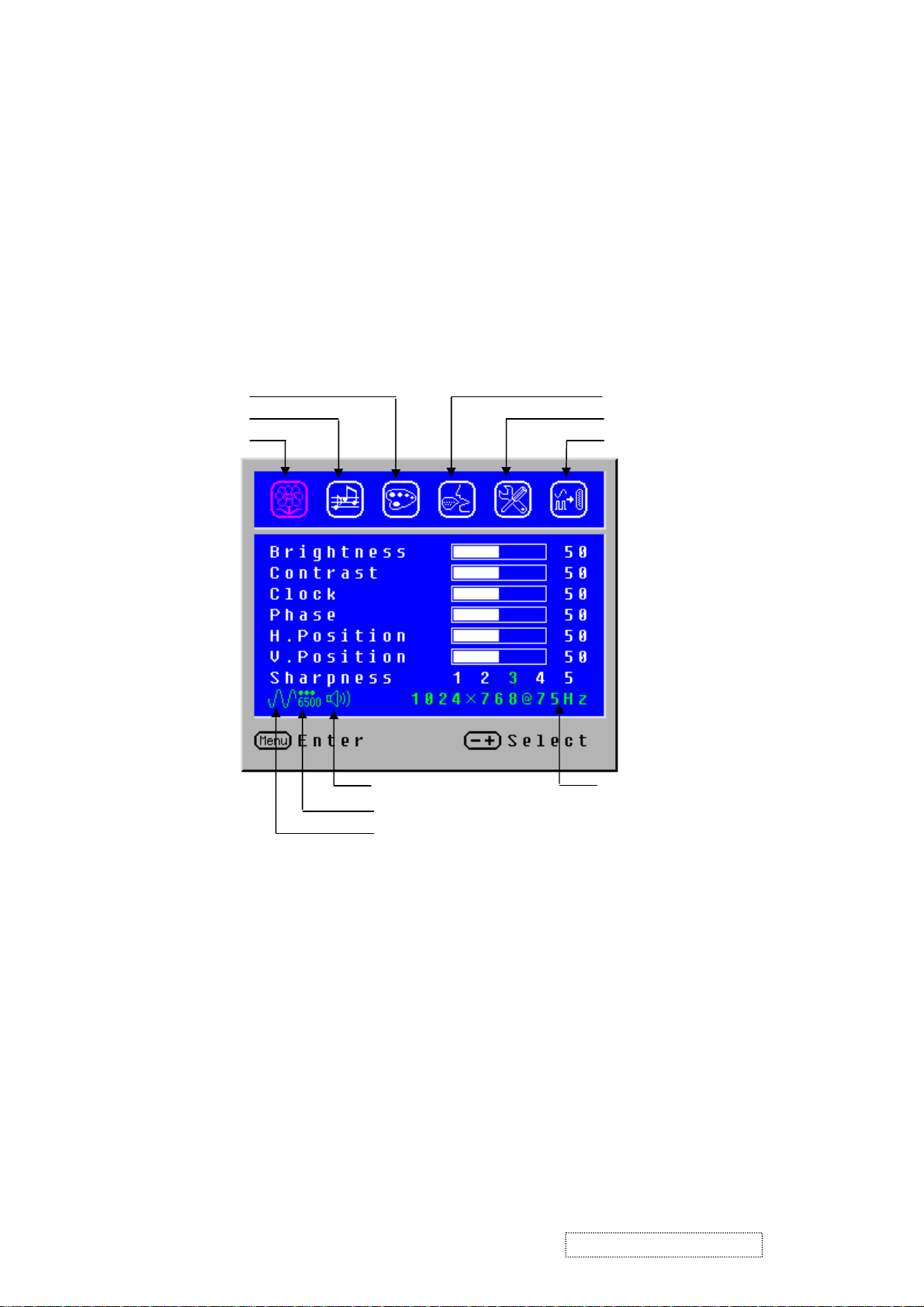
Color Temp. Selection
Volume Adjustment
V-Position
Image Adjustment
50
Language Selection
s
Set
Input Source Selection (optional)
Audio Current Status Source Resolution & Frequency
Color Temp. Status
Input Source Status (Optional)
Notes
The OSD disappears several seconds after you stop pressing the buttons while
performing an adjustment.
Any changes are automatically saved in the memory when the OSD disappears.
Turning off the power should be avoided while using the menu.
Adjustments for clock, phase and positions are saved for each signal timing. Except
for these adjustments, all other adjustments have only one setting which applies to
all signal timings.
The color will change from white to pink while the function is selected.
ViewSonic Corporation Confidential
11
-
Do Not Copy VE702m
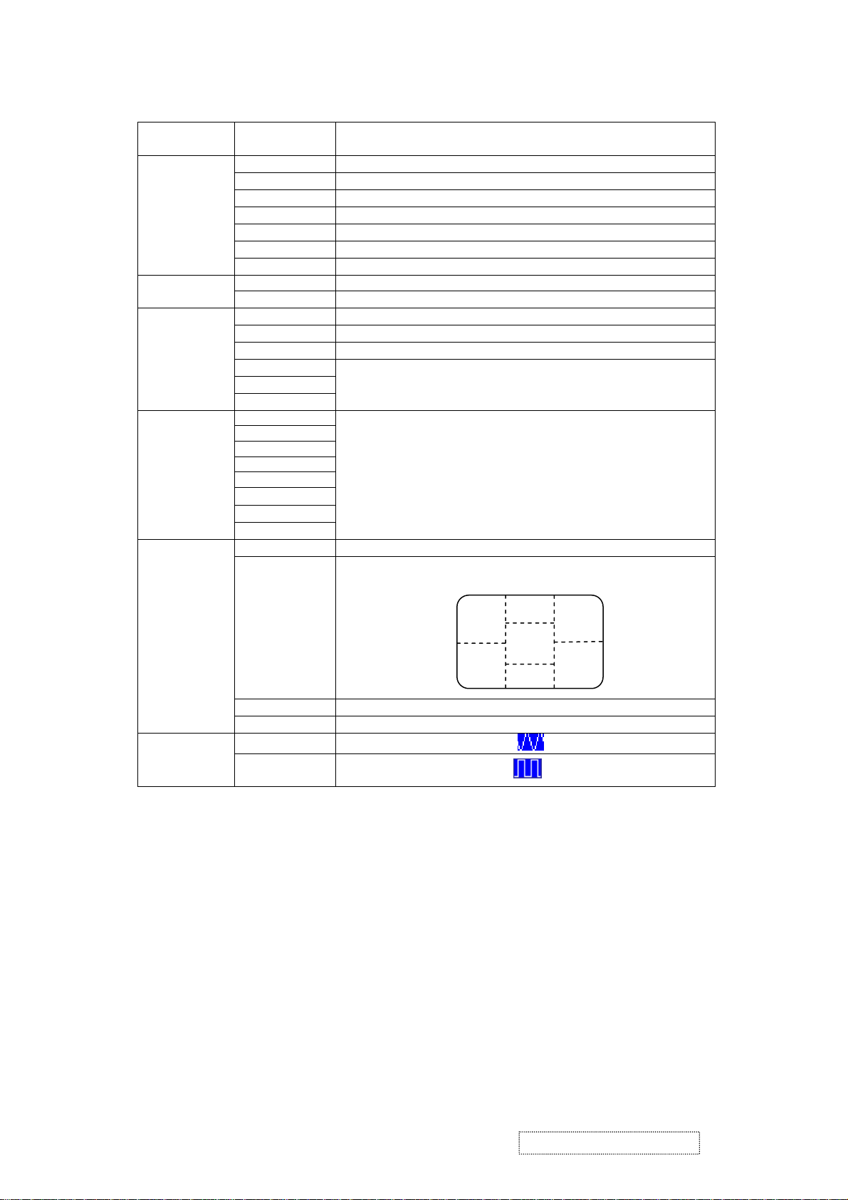
Adjustment of
Function Definition
Screen
Primary
Directory
Image
Audio
Color
Language
Settings
Secondary
Directory
Brightness
Contrast
Clock
Phase
H. Position
V. P o si t io n
Sharpness
Volume
Mute
9300K
7500K
6500K
User/Red
User/Green
User/Blue
English
Français
Italiano
Deutsch
Español
ֲء
ㅔԧЁ᭛
᧯խ֮
OSD Timeout
OSD Position
Description
Adjust the brightness of the screen.
Adjust the contrast of the image.
Adjust the clock pulse of the image.
Adjust the focus of the image.
Move the image left and right on the screen.
Move the image up and down on the screen.
Adjust the picture sharpness of lower resolutions.
Adjust the volume of the audio.
Set up the audio to be mute on or off.
Set up the color temp. to be 9300K white color.
Set up the color temp. to be 7500K white color.
Set up the color temp. to be 6500K white color.
Adjust red/green/blue gain.
Select the language you want.
Adjust OSD display time setting.
Move OSD display position to any one of the following 5
positions within the overall screen.
1
2
3
4
Auto Setting
Recall
Input Source
Analog
Digital
(Optional)
Direct
You can skip the Menu pages and display an adjustment scale directly by using the
following button operations:
Brightness: Press the Brightness Button when the Menu is not displayed.
Contrast: Press the Contrast Button when the Menu is not displayed.
Auto Setting: Press the Auto Button when the Menu is not displayed.
Turbo: Press the Input Button when the Menu is not displayed.
Pct: Picture Mode (High brightness)
Text: Text Mode (Normal)
Eco Economy (Brightness of back-light is reduced)
Changing to a lower brightness mode can lessen eye fatigue.
Change from Picture Mode to Text Mode when working with text.
Change from Text Mode to Economy Modes when viewing the screen for long
periods.
Set up to adjust clock, phase and positions automatically.
Restore to factory settings
Select Analog input source:
Select Digital input source:
5
ViewSonic Corporation Confidential
12
-
Do Not Copy VE702m
Hot Keys for Function Controls
[Power on/off] Main Menu
[Auto/Exit] Input toggle (Analog or Digital) or Auto Image Adjust.
[+] or [-] To immediately activate Contrast menu. It should be change to Brightness
OSD by push button [2]
[+] + [-] Recall both of Contrast and Brightness to default
[Power on/off] + [Auto/Exit] Toggle 720x400 and 640x400 mode when input 720x400 or 640x400
mode
[Power on/off] + [+] + [-] White Balance. (Not shown on user’s guide)
[Power on/off] + [-] Power Lock
[Power on/off] + [+] OSD Lock
1.Turn off [Power on/off] button
2. [+] + [-] + [Power on/off] at same
All Mode Reset. It will erase all end users’ setting and restore the factory
defaults.
time
3. Press [Menu]
1.Turn off [Power on/off] button
2. [+] + [-] + [Power on/off] at same
Burn in Mode. After entering Burn in Mode, press Power on/off button,
you will find the information about this BIOS
time
3. Press [Menu]
Remark: All the short cuts function are only available while OSD off
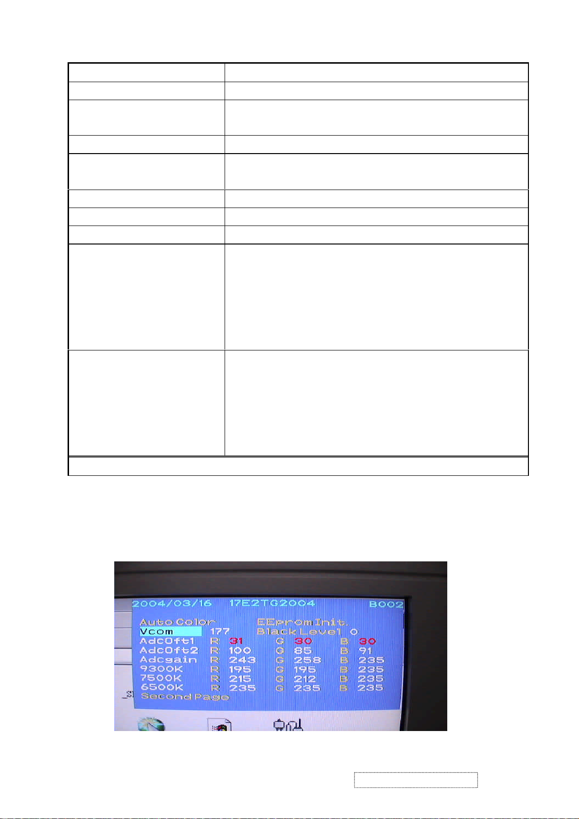
Hot Keys for Factory Control
1. Turn off [Power on/off] button.
2. Press [+] + [-] + [Power on/off] at same time
3. Press [Menu]
Then you will see the BIOS update picture show in the screen as below.
ViewSonic Corporation Confidential
13
-
Do Not Copy VE702m
4. Circuit Description
Circuit Description
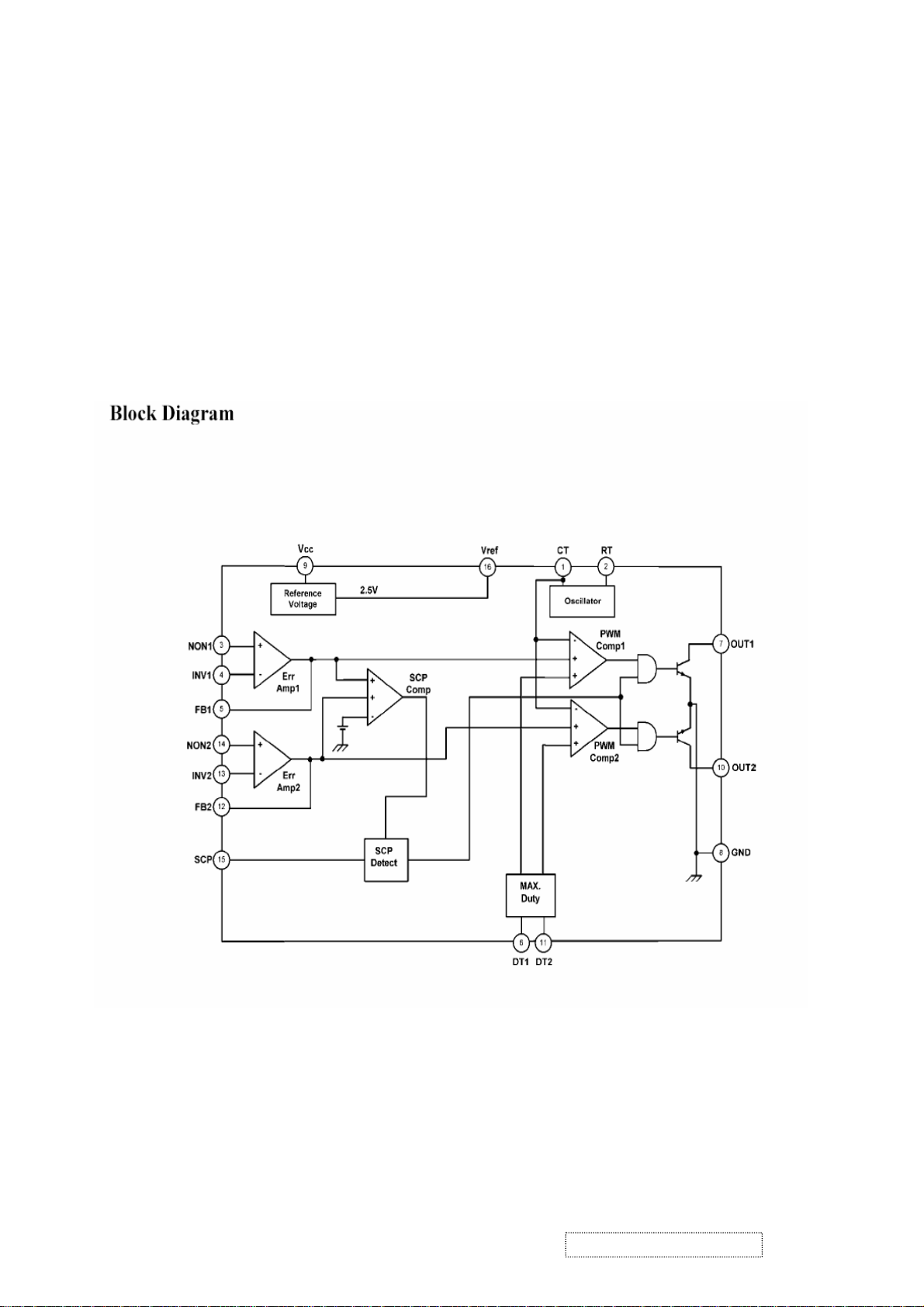
1. Power supply (DC/DC Converter)
The AT1741 is 2-channel PWM switching regulator controllers that contains an
on-chip 2.5V reference, two error amplifier, an adjustable oscillator, two
dead-time comparators, under voltage lockout circuitry and 2 common-emitter
output. It is idea for step-up, step-down, and inverting converter.
ViewSonic Corporation Confidential
14
-
Do Not Copy VE702m
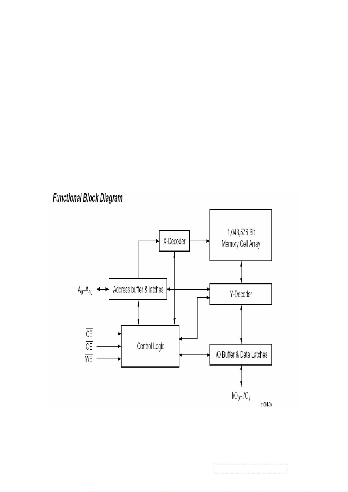
2. Flash Memory
The F29C51001T/F29C51001B is a 1 Megabit, 5.0 Volt-only Flash Memory organized as 131,072
bytes of 8 bits each. This device is designed to use a 4.7 Volt to 5. 3 Volt power supply to perform
in-system programming.
The 1 Megabit memory array is divided into thirty-two uniform blocks of 4 Kbytes each for data and/or
code storage.
The block architecture allows users to flexibly make chip erase or block erase operation. The block
erase feature allows a particular block to be erased and reprogrammed without affecting the data in
other blocks. After the device performs chip erase or block erase operation, it can be reprogrammed on
a byte-by-byte basis.
ViewSonic Corporation Confidential
15
-
Do Not Copy VE702m
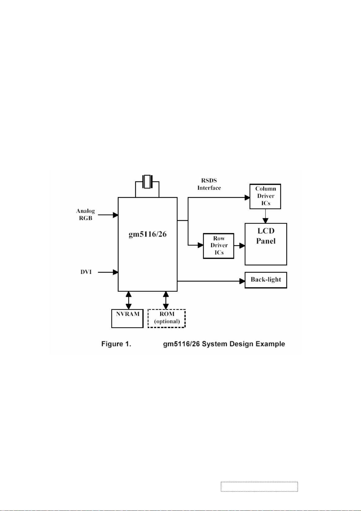
3. GM5120
The gm5116/26 is a graphic processing IC for Liquid Crystal Display (LCD) monitors at XGA/SXGA
resolution. It provides all key IC functions required for the highest quality LCD monitors. On-chip
TM
functions include a high-speed triple-ADC and PLL, Ultra-Reliable DVI
zoom and shrink scaling engine, an on-screen display (OSD) controller, digital color controls and an
on-chip microcontroller (OCM). With this level of integration, the gm5116/26 devices simplify and
reduce the cost of LCD monitors while maintaining a high-degree of flexibility and quality.
receiver, a high quality
4. LVDS (THC63LVDM83A)
The THC63LVDM83A transmitter converts 28 bits of CMOS/TTL data into LVDS (Low Voltage
Differential Signaling) data stream. A phase-locked transmit clock is transmitted in parallel with the
data streams over a fifth LVDS link. The HC63LVDM83A can be programmed for rising edge or
falling edge clocks through a dedicated pin. The THC63LVDF84A receiver converts the LVDS data
streams back into 28 bits of CMOS/TTL data with falling edge clock. At a transmit clock frequency of
85MHz, 24 bits of RGB data and 4 bits of LCD timing and control data (HSYNC, VSYNC, CNTL1,
CNTL2) are transmitted at a rate of 595 Mbps per LVDS data channel.
ViewSonic Corporation Confidential
16
-
Do Not Copy VE702m
5. Adjusting Procedure
A. Function Test and Alignment Procedure
1. All Modes Reset
You should do “All Model Reset” (Refer to Chap 3. Hot Keys for Function Controls) first. This
action will allow you to erase all end-user’s settings and restore the factory defaults.
2. Auto Image Adjust
The Auto Adjust is aimed to offer a best screen quality by built-in ASIC. For optimum screen
quality, the user has to adjust each function manually.
A.Turn the computer and LCD monitor on.
B. Press the ‘Auto’ button on monitor keypad to Auto Adjust.
C. The LCD monitor will start the Auto Adjust process automatically and run for 10 consecutive
seconds, during which time you will notice the image change.
3. Firmware
Test Patten : Burn in Model (Refer to Chap3. Hot Keys for Function Control)
-Make sure the F/W is the latest version.
4. DCC
Test Patten: EDID program
-Make sure it can pass test program.
5. Window Shut Down
Test Signal: 1280*1024@60Hz
Test Pattern:
Checkered Pattern Every One Pixel (50%Green & 50%Blue)
Inspection Item: Flicker, Mura
6. Window BG
Test Signal: 1280*1024@60Hz
(Refer to Page 22 Figure 5,6)(Refer to Page 22,
Test Pattern:
Window standard pattern
Inspection Item: Line Defect, Function Defect & Mura
ViewSonic Corporation Confidential
17
-
Do Not Copy VE702m
7. 25 Gray
Test Signal: 1280*1024@60Hz
Test Pattern:
Full Screen 25% White (Gray)
Inspection Item: Particle, Line Defect & Mura
8. 50 Gray
Test Signal: 1280*1024@60Hz
Test Pattern:
Full Screen 50% White (Gray)
Inspection Item: Bright Dot, Particle, Line Defect & Mura
9. White Box
Test Signal: 1280*1024@60Hz
Test Pattern:
(Refer to Page 22, Figure 7)
Window standard pattern
Inspection Item: Particle, Line Defect, Power, Image Remain & Mura
10. Black Box
Test Signal: 1280*1024@60Hz
Test Pattern:
(Refer to Page 21, Figure 3)
Window standard pattern
Inspection Item: Bright Dot, Line Defect & Power
ViewSonic Corporation Confidential
18
-
Do Not Copy VE702m
 Loading...