

ViewSonic VE700-1,VLCDS23724-1W,VA720-2,VLCDS23724-2W Service manual
Service Manual
ViewSonic VE700-1
VA720-2
Model No. VLCDS23724-1W
VLCDS23724-2W
17” Color TFT LCD Display
ViewSonic
(VE700-1_SM_545 - Rev. 1a – May 2002)
381 Brea Canyon Road, Walnut, California 91789 USA - (800) 888-8583
Copyright
Copyright ¤ 2002 by ViewSonic Corporation. All rights reserved. No part of this publication may be
reproduced, transmitted, transcribed, stored in a retrieval system, or translated into any language or
computer language, in any form or by any means, electronic, mechanical, magnetic, optical, chemical,
manual or otherwise, without the prior written permission of ViewSonic Corporation.
Disclaimer
ViewSonic makes no representations or warranties, either expressed or implied, with respect to the
contents hereof and specifically disclaims any warranty of merchantability or fitness for any particular
purpose. Further, ViewSonic reserves the right to revise this publication and to make changes from time
to time in the contents hereof without obligation of ViewSonic to notify any person of such revision or
changes.
Trademarks
ViewSonic is a registered trademark of ViewSonic Corporation.
All other trademarks used within this document are the property of their respective owners.
Revision History
Revision Date Description Of Changes Approval
1a 7/17/02 Initial Reversion DCN-2254 K.Yang
ViewSonic Corporation
ii
Confidential – Do Not Copy
VE700-1
VA720-2

TABLE OF CONTENTS
PRECAUTIONS AND NOTICES...............................................................................1
1.
SPECIFICATIONS ....................................................................................................2
2.
LOCATION OF CONTROLS.....................................................................................3
3.
INTERNAL CONNECTOR PIN DEFINITION ............................................................4
4.
CABLE PIN DEFINITION.........................................................................................10
5.
BLOCK DIAGRAM...................................................................................................13
6.
TROUBLE SHOOTING FLOW CHART...................................................................14
7.
SPARE PARTS LIST................................................................................................20
8.
EXPLODED DIAGRAM............................................................................................2 5
9.
SCHEMATIC DIAGRAMS........................................................................................2 7
10.
11. PCB LAYOUT DIAGRAM........................................................................................36
ViewSonic Corporation
iii
Confidential – Do Not Copy
VE700-1
VA720-2
PRECAUTIONS AND NOTICES
1.
Prior to using this manual, please ensure that you have carefully followed all the procedures
outlined in the user manual for this product.
Read all of these instructions.
z
Save these instructions for later use.
z
Follow all warnings and instructions marked on the product.
z
Do not use this product near water.
z
This display should be installed on a solid horizontal base.
z
When cleaning, use only a neutral detergent cleaner with a soft damp cloth. Do not spray
z
with liquid or aerosol cleaners.
Do not expose this display to direct sunlight or heat. Hot air may cause damage to the cabinet
z
and other parts.
Adequate ventilation must be maintained to ensure reliable and continued operation and to
z
protect the display from overheating. Do not block ventilation slots and openings with objects or
install the display in a place where ventilation may be hindered.
Do not install this display near a motor or transformer where strong magnetism is generated.
z
Images on the display will become distorted and the color irregular.
Do not allow metal pieces or objects of any kind fall into the display from ventilation holes.
z
Slots and openings in the cabinet and the back or bottom are provided for ventilation, to ensure reliable
operation of the product and to protect it from overheating, those openings muse not be blocked or
covered. The openings should never be blocked by placing the product on a bed, sofa, rug, or other
similar surface. This product should never be placed near or over a radiator or heat register. This
product should not be placed in a built-in installation unless proper ventilation is provided.
ViewSonic Corporation
1
Confidential – Do Not Copy
VE700-1
VA720-2

SPECIFICATIONS
2.
LCD panel type 17.0” TFT(AU)
Power Consumption 40 W
Displayable Resolution SXGA 1280 x 1024 maximum
Pixel dimension 0.264 mm x 0.264 mm
Display Color 16.7 M
Viewing Angle
(CR=10)
Horizontal: ±75
Vertical: ±70
°
°
RESPONSE TIME 40 ms typ.
Contrast Ratio 400:1 typ.
Brightness 250 cd / m2 typ.
Active Display Area 337.9 mm horizontal x 270.3mm vertical
AC/DC adapter Input:AC 87~264V,47~63 Hz
Output:+12V DC.
Dimensions ( WxHxD ) 413.8 mm(W) x 403(H) mm x 229(D) mm
Weight 6.2 kg (unit)
Input connector 15 Pin D-Sub.
Power management < 2W in Active Off mode
Temperature Operating : 0°C ~ +40°C
Storage : -20°C ~ +60°C
ViewSonic Corporation
2
Confidential – Do Not Copy
VE700-1
VA720-2
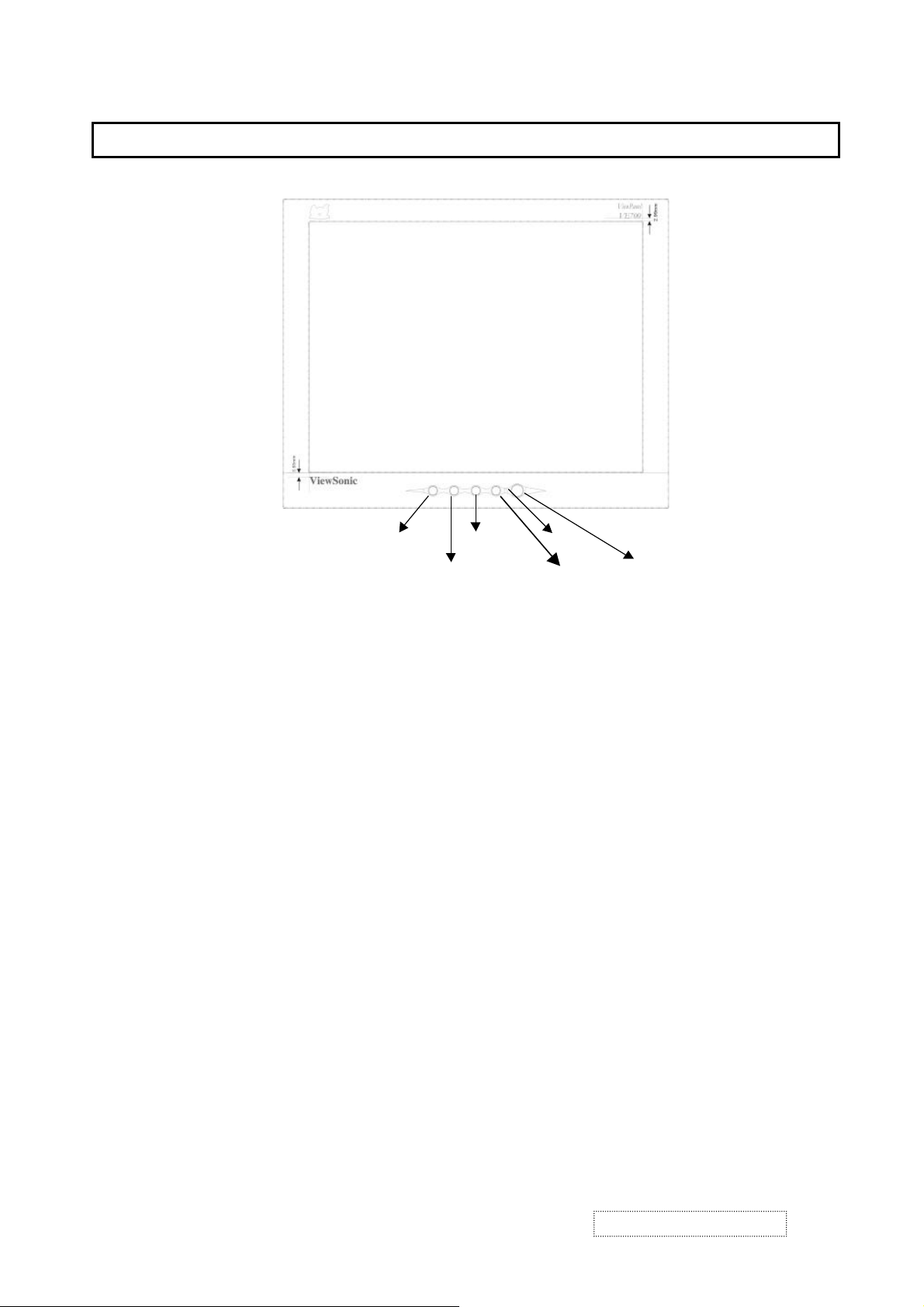
LOCATION OF CONTROLS
3.
ϧ
[1]MENU ADJUST
ADJUST ϰ
[2]ENTER POWER
LED
Figure 3-1: Front Panel Controls & Indicators
1) POWER :
Press the power key to turn the monitor on. Press it again to turn the monitor off.
2) [1]MENU :
Enter or exit the OSD adjustment menu.it also exit from the submenu back to previous menu.
3) [2]ENTER :
To confirm the current selection
4) ADJUST ϧ (UP)
To scroll up in menu or to increase value of selected item.
5) ADJUST ϰ :(DOWN)
To scroll down in menu or to decrease value of selected item.
6) POWER INDICATOR :
The LED will light with green color in normal on state,and will light with orange color in power saving mode.
7) Brightness/Contrast: press button UP/DOWN .
8) Auto Image Adjust : press button [2] .
9) OSD lock and unlock: press two buttons [1]&[Up] simultaneously for 10 seconds.
10) Power lock and unlock: press two buttons [1]&[Down] simultaneously for 10 seconds.
ViewSonic Corporation
3
Confidential – Do Not Copy
VE700-1
VA720-2

INTERNAL CONNECTOR PIN DEFINITION
4.
SXGA I/F BOARD(DPWBN5408T8----)
:Key Switch for OSD Adjustment,Power Switch and Brightness Control
JP4
Input Terminal
Connector P/N:VCNCP0908REJST-
Pin NO. Symbol Function
1 MENU For OSD Adjustment
2 ENTER For OSD Adjustment
3 UP For OSD Adjustment
4 DOWN For OSD Adjustment
5 RED For LED
6 GREEN For LED
7 PSW Power ON/OFF
8 GND
JP1 :Output Terminal for inverter unit
Connector P/N :VCNCP0906REJST-
Pin NO. Symbol Function
1
2
3
4
5
6
VIN Supply Voltage for Inverter unit(DC+12)
VIN Supply Voltage for Inverter unit(DC+12)
ON/OFF
DIMMING
GND
GND
JP3:Power Input Terminal
Connector P/N :QJAKP1044T8----
Pin NO. Symbol Function
1 POWER DC+12V
2 POWER DC+12V
3 GND GND
4 GND GND
ViewSonic Corporation
V
4
Confidential – Do Not Copy
VE700-1
VA720-2
XGA I/F BOARD (DPWBN5408T8----)
J1:Signal input terminals
Connector P/N:QCNCD1145T8----
Pin NO. Symbo Function
1 RED RED Video input signal
2 GREEN GREEN Video input signal
3 BLUE BLUE Video input signal
4 GND GND
5 RETURN GND
6 RED RETURN GND for RED video signal
7 GREEN RETURN GND for GREEN video signal
8 BLUE RETURN GND for BLUE video signal
9 5V_DDC TO DDC PIN 8
10 SYNC. RETURN GND for SYNC. Signal
11 GND GND
12 DDC data TO DDC PIN 5(SDA)
13 H SYNC Horizontal Sync.signal
14 V SYNC Vertival Signal
15 DDC clock TO DDC PIN 6(SCL)
J2:Output terminal for LCD PANEL
Connector P/N:QCNCP2001T8----
Pin NO. Symbo Function
1 EPCL
2 ELOAD
3 EDO/I
4 GND
5 XECLK
6 GND
7 XEDINV
8 GND
9 XOOR7
10 XOOR6
11 XOOR5
12 XOOR4
13 XOOR3
14 XOOR2
15 XOOR1
16 XOOR0
ViewSonic Corporation
5
Confidential – Do Not Copy
VE700-1
VA720-2
Pin NO. Symbo Function
17 XOOG7
18 XOOG6
19 XOOG5
20 XOOG4
21 XOOG3
22 XOOG2
23 XOOG1
24 XOOG0
25 GND
26 XOOB7
27 XOOB6
28 XOOB5
29 XOOB4
30 XOOB3
31 XOOB2
32 XOOB1
33 XOOB0
34 OPOL
35 OLOAD
36 ODOM
37 GND
38 XOCLK
39 GND
40 XODINV
41 GND
42 XOFR7
43 XOFR6
44 XOFR5
45 XOFR4
46 XOFR3
47 XOFR2
48 XOFR1
49 XOFR0
50 XOFG7
ViewSonic Corporation
6
Confidential – Do Not Copy
VE700-1
VA720-2
J3:Output terminal for LCD PANEL
Connector P/N:QCNCP2001T8----
Pin NO. Symbo Function
1 XFOR7
2 XFOR6
3 XFOR5
4 XFOR4
5 XFOR3
6 XFOR2
7 XFOR1
8 XFOG0
9 XFOG7
10 XFOG6
11 XFOG5
12 XFOG4
13 XFOG3
14 XFOG2
15 XFOG1
16 XFOG0
17 GND
18 XFOB7
19 XFOB6
20 XFOB5
21 XFOB4
22 XFOB3
23 XFOB2
24 XFOB1
25 XFOB0
26 XFFR7
27 XFFR6
28 XFFR5
29 XFFR4
30 XFFR3
31 XFFR2
32 XFFR1
33 XFFR0
34 GND
35 XFFG7
ViewSonic Corporation
7
Confidential – Do Not Copy
VE700-1
VA720-2
36 XFFG6
Pin NO. Symbo Function
37 XFFG5
38 XFFG4
39 XFFG3
40 XFFG2
41 XFFG1
42 XFFG0
43 XFFB7
44 XFFB6
45 XFFB5
46 XFFB4
47 XFFB3
48 XFFB2
49 XFFB1
50 XFFB0
J1:Output terminal for LCD PANEL
Connector P/N:QCNCP2002T8----
Pin NO. Symbo Function
1 XOFG6
2 XOFG5
3 XOFG4
4 XOFG3
5 XOFG2
6 XOFG1
7 XOFG0
8 GND
9 XOFB7
10 XOFB6
11 XOFB5
12 XOFB4
13 XOFB3
14 XOFB2
15 XOFB1
16 XOFB0
17 V+3.3V
18 V+3.3V
19 V+3.3V
ViewSonic Corporation
8
Confidential – Do Not Copy
VE700-1
VA720-2
20 AVDD_+9.6V
Pin NO. Symbo Function
21 AVDD_+9.6V
22 AVDD_+9.6V
23 YV1_+25.09V
24 YVEE_-4.96V
25 GND
26 GALE_ON
27 YOE
28 YCLK
29 YDIO2
30 YDIO1
SW board (DPWBN5415T8----)
CN4:Output Terminal for OSD,power and brightness control
Use connector:VCNCP0908REJST-
Pin NO. Symbo Function
1 KEY
2 LED-G
3 LED-R
4 MENU S1 For OSD Adjustment
5 SELECT S2 For OSD Adjustment
6 GROUND
7 DOWN S4 For OSD Adjustment
8 UP S3 For OSD Adjustment
INVERTER
CON1:Inverter input Terminal
Pin Symbo Function
1 VBL +12V Power Supply for backlight
2 VBL +12V Power Supply for backlight
3 BLON Backlight on/off signal
(HI:backlight ON,Low:backlight OFF)TTL level
4 DIMMI Ground for VBL line ,VDIM and BLON
5 GND
6 GND
ViewSonic Corporation
9
Confidential – Do Not Copy
VE700-1
VA720-2
 Loading...