

ViewSonic VE700-1,VLCDS23724-1W Service manual
Service Manual
ViewSonic VE700-1
Model No. VLCDS23724-1W
17” Color TFT LCD Display
ViewSonic
(VE700-1_SM_545 Rev. 1a – Jan. 2004)
381 Brea Canyon Road, Walnut, California 91789 USA - (800) 888-8583
Copyright
Copyright
reproduced, transmitted, transcribed, stored in a retrieval system, or translated into any language or
computer language, in any form or by any means, electronic, mechanical, magnetic, optical, chemical,
manual or otherwise, without the prior written permission of ViewSonic Corporation.
Disclaimer
ViewSonic makes no representations or warranties, either expressed or implied, with respect to the
contents hereof and specifically disclaims any warranty of merchantability or fitness for any particular
purpose. Further, ViewSonic reserves the right to revise this publication and to make changes from time
to time in the contents hereof without obligation of ViewSonic to notify any person of such revision or
changes.
Trademarks
Optiquest is a registered trademark of ViewSonic Corporation.
ViewSonic is a registered trademark of ViewSonic Corporation.
All other trademarks used within this document are the property of their respective owners.
2003 by ViewSonic Corporation. All rights reserved. No part of this publication may be
¤
Revision History
Revision Date Description Of Changes Approval
1a 07/17/02 Initial Release DCN- 2254 K. Yang
09/01/04
1b
Revise DCN-3607 Angela Luh
Angela Luh
ViewSonic Corporation Confidential
i
-
Do Not Copy VE700

TABLE OF CONTENTS
1. Precautions and Safety Notices
2. Specification
3. Front Panel Function Control Description
4. Circuit Description
5. Adjusting Procedure
6. Trouble Shooting Flow Chart
7. Recommended Spare Parts List
8. Exploded Diagram And Spare Parts List
9. Block Diagram
10. Schematic Diagrams
11. PCB Layout Diagrams
1
2
4
5
6
7
11
15
18
19
21
ViewSonic Corporation Confidential
ii
-
Do Not Copy
VE700

1. Precautions and Safety Notices
Prior to using this manual, please ensure that you have carefully followed all the procedures outlin ed in the user manual fo r
this product.
Read all of these instructions.
Save these instructions for later use.
Follow all warnings and instructions marked on the product.
Do not use this product near water.
This display should be installed on a solid horizontal base.
When cleaning, use only a neutral detergent cleaner with a soft damp cloth. Do not spray with liquid or aerosol cleaners.
Do not expose this display to direct sunlight or heat. Hot air may cause damage to the cabinet and other parts.
Adequate ventilation must be maintained to ensure reliable and continued operation and to protect the display from
overheating. Do not block ventilation slots and openings with objects or install the display in a place where ventilation may
be hindered.
Do not install this display near a motor or transformer where strong magnetism is generated. Images on the display will
become distorted and the color irregular.
Do not allow metal pieces or objects of any kind fall into the display from ventilation holes.
Slots and openings in the cabinet and the back o r bottom are provided for ventilation, to ensure reliable o peration of the
product and to protect it from overheating, those openings muse not be blocked or covered. The openings should never be
blocked by placing the product on a bed, sofa, rug, or other similar surface. This product should never be placed near or over
a radiator or heat register. This product should not be placed in a built-in installation unless proper ventilation is provided.
ViewSonic Corporation Confidential
1
-
Do Not Copy VE700

2. Specification
2.1. PRODUCT SPECIFICATIONS
LCD panel type
17.0” TFT(AU)
Power Consumption
Displayable Resolution
Pixel dimension
Display Color
Viewing Angle
(CR≥10)
Response Time
Contrast Ratio
Brightness
Active Display Area
AC/DC adapter
Dimensions ( WxHxD )
Weight (Net / Gross)
5.4 / 7.6 kg (unit)
40 W
SXGA 1280 x 1024 maximum
0.264 mm x 0.264 mm
16.7 M
Horizontal: ±70°
Vertical: ±70°
Tr:12ms Tf:4ms( typ).
450:1 typ.
200 cd/m2 (min),260 cd / m2 typ.
337.9 mm horizontal x 270.3mm vertical
Input:AC 100~264V,47~63 Hz
Output:+12V DC.
415 mm(W) x 403(H) mm x 229(D) mm
Input connector
Power management
Temperature
15 Pin D-Sub.
YES
Operating : 0°C ~ +40°C
Storage : -20°C ~ +60°C
ViewSonic Corporation Confidential
2
-
Do Not Copy VE700
2.2. FACTORY SUPPORTING MODES
Primary Preset
Factory Preset Modes
VESA 1280 x 1024 @ 60 Hz
1. VESA 640 x 350 @ 70Hz, 31.47kHz, -/+
2. VESA 720 x 400 @ 70Hz, 31.467kHz, +/-
3. VESA 640 x 480 @ 60Hz, 31.469kHz, -/-
4. VESA 640 x 480 @ 72Hz, 37.861kHz, -/-
5. VESA 640 x 480 @ 75Hz, 37.5kHz, -/-
6. MAC 640 x 480 @ 67Hz, 35kHz,
7. VESA 800 x 600 @ 56Hz, 35.156kHz, +/+
8. VESA 800 x 600 @ 60Hz, 37.879kHz, +/+
9. VESA 800 x 600@ 72Hz, 48.077kHz,+/+
10. VESA 800 x 600 @ 75Hz, 46.875kHz, +/+
11. MAC 832 x 624 @ 75Hz, 49.725kHz,
19. MAC 1152 x 870 @ 75Hz, 68.6kHz,
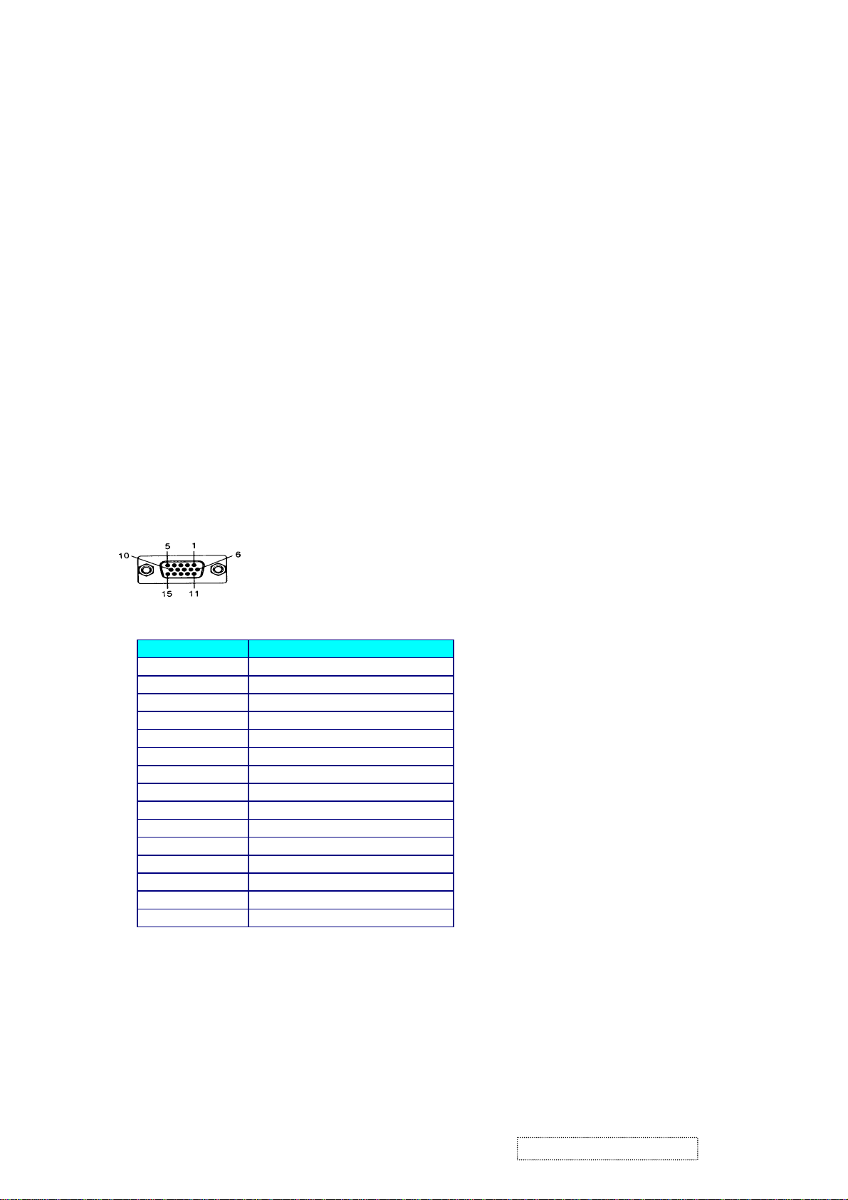
2.3. D-SUB CONNECTOR
This section describes the pin assignment of the LCD’s video connector. It is called 15 Pin Mini D-sub Connector.
Pin NO.
1
2
3
4
5
6
7
8
9
10
11
12
13
14
15
Signal Connector
Red Video Signal
Green Video Signal
Blue Video Signal
N.C.
Ground
Ground
Ground
Ground
+5v
Ground
N.C.
DDC data
Horizontal sync signal
Vertical sync signal
DDC clock
ViewSonic Corporation Confidential
3
-
Do Not Copy VE700
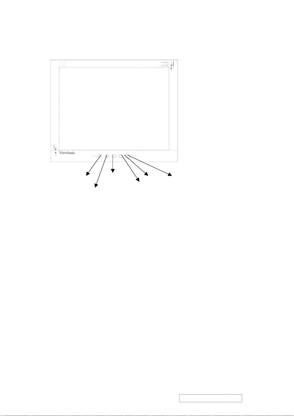
3. Front Panel Function Control Description
Location of Controls
[1]MENU ADJUST
[2]ENTER
ADJUST ▼
▲ LED POWER
1) POWER :
Press the power button to turn the monitor on. Press it again to turn the monitor off.
2) [1]MENU :
Enter or exit the OSD adjustment menu. It also exit from the submenu back to previous menu.
3) [2]ENTER :
To confirm the current selection
4) ADJUST ▲ (UP)
To scroll up in menu or to increase value of selected item.
5) ADJUST ▼ :(DOWN)
To scroll down in menu or to decrease value of selected item.
6) POWER INDICATOR :
The LED will light with green color in normal on state, and will light with orange color in power saving mode.
7) Brightness/Contrast: press button UP/DOWN .
8) Auto Image Adjust : press button [2] .
9) OSD lock and unlock: press two buttons [1]&[up] simultaneously for 10 seconds.
10) Power lock and unlock: press two buttons [1]&[Down] simultaneously for 10 seconds.
11) ALL RESET: First, power off the monitor, un-plug the AC cord, then press “▲ ” and “Power “ key at the same
time and plug the AC cord.
12) Factory Mode:First, power off the monitor, un-plug the AC cord and be sure the signal cable is connected(D-sub
connected) , then press “2” and “Power “ key at the same time and plug the AC cord.
13) RUN-IN mode: First, power off the monitor, un-plug the AC cord and be sure the signal cable is not connected (D-sub
not connected) , then press “2” and “Power “ key at the same time and plug the AC cord.
14) ISP mode:First, power off the monitor, unplug the AC cord, then press “2” and “Power “ and “down” key at the same
time and plug the AC cord.
15) AUTO color: then press “1” and “▲“ and “▼” key at the same time.
ViewSonic Corporation Confidential
4
-
Do Not Copy VE700

4 Circuit Description
A. DC-DC CONVERTER AND LDO
This brick converts the 12V input voltage to 5V for panel use and U9 converts the voltage from 5V to 3.3V ,
U8 converts the voltage from 5V to 2.5V for controller use.
It consists of a PWM IC (LM2596), flywheel Diode (D4), buck choke (L1), and capacitor (C68,C69).
U7 (LM2596) is a PWM generator working at 150Khz.
Self protection features include a two stage frequency reducing current limit for the output switch and an over
temperature shutdown for complete protection under fault condition.
U8 is a low dropout voltage and fast trasient response three terminal regulator, the output voltage is 2.5V fixed.
U9 is a low dropout voltage and fast trasient response three terminal regulator, the output voltage is 3.3V fixed.
B. Scaling controller
The gm2121 is a graphics processing IC for Liquid Crystal Display (LCD) monitor at SXGA resolution . It provides
a high-speed triple-ADC and PLL,a high quality zoom and shrink scaling engine , an on-screen display (OSD)
controller, digital color controls, an on-chip micro-controller ( OCM ) and industry standard dual four channel
LVDS transmitter for direct connect to LCD panel with LVDS interface.
The triple-ADC is to convert RGB analog signal to digital signal. The gm2121 is a complete 8-bit up to 162MHz
(SXGA 75Hz / UXGA 60Hz) monolithic analog interface optimized for capturing RGB graphic signal, +3.3V
and +2.5V power supply is necessary.
The gm2121 scaling filter can combine it’s advanced scaling with a pixel-replication type scaling function.this
is useful for improving the sharpness and definition of graphics when scaling at high zoom factors. Gm2121 provides
an 8 to 10 bit look-up table (LUT) for each input color channel intended for Gamma correction and to compensate for
a non-linear response of the LCD panel . A 10-bit output results in an improved color depth control. The 10-bit output
is then dithered down to 8 bits( or 6 bits) per channel at the display .
ViewSonic Corporation Confidential
5
-
Do Not Copy VE700
 Loading...