

ViewSonic VE510s-1,VE510b-1,VS10040 Service manual

Service Manual
ViewSonic VE510s/b-1-1
Model No. VS10040
15” Color TFT LCD Display
ViewSonic
(VE510s/b-1_SM_773 Rev. 1b Feb. 2005)
381 Brea Canyon Road, Walnut, California 91789 USA - (800) 888-8583
Copyright
Copyright
2005 by ViewSonic Corporation. All rights reserved. No part of this publication may be
¤
reproduced, transmitted, transcribed, stored in a retrieval system, or translated into any language or
computer language, in any form or by any means, electronic, mechanical, magnetic, optical, chemical,
manual or otherwise, without the prior written permission of ViewSonic Corporation.
Disclaimer
ViewSonic makes no representations or warranties, either expressed or implied, with respect to the
contents hereof and specifically disclaims any warranty of merchantability or fitness for any particular
purpose. Further, ViewSonic reserves the right to revise this publication and to make changes from time
to time in the contents hereof without obligation of ViewSonic to notify any person of such revision or
changes.
Trademarks
Optiquest is a registered trademark of ViewSonic Corporation.
ViewSonic is a registered trademark of ViewSonic Corporation.
All other trademarks used within this document are the property of their respective owners.
1a
1b
DCN Number ECR Number
23/03/04
02/04/05
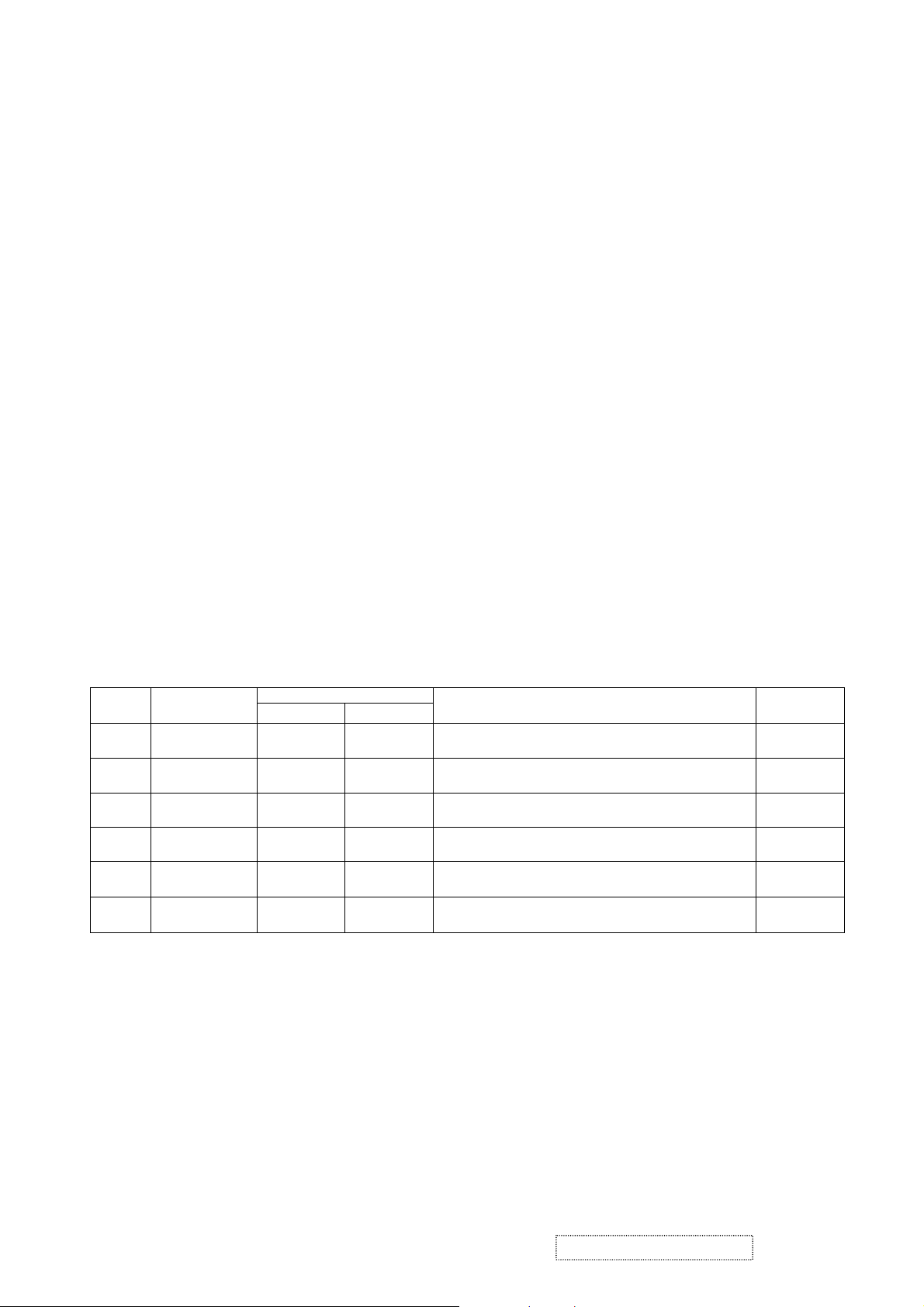
Revision History
Documents Number
4
221
4890
4805
Description of Changes EditorRevision SM Editing Date
Initial Release
Change Scale From MRT MVRL-HN To Realtek TTL2013
Change Panel From LG LM150X08 16/32 ms
To GBM/DDL GB150XQQ3-A000 16/30ms
A. Lu
A. Lu
ViewSonic Corporation Confidential
i
-
Do Not Copy VE510s/b-1

TABLE OF CONTENTS
1. Precautions and Safety Notices
2. Specification
3. Front Panel Function Control Description
4. Circuit Description
5. Adjustment Procedure
6. Troubleshooting Flow Chart
7. Recommended Spare Parts List
8. Exploded Diagram and Spare Parts List
9. Block Diagram
10. Schematic Diagrams
11. PCB Layout Diagrams
1
3
9
14
21
35
37
45
47
48
54
ViewSonic Corporation Confidential
ii
-
Do Not Copy VE510s/b-1

1. Precautions and Safety Notices
1. Appropriate Operation
(1) Turn off the product before cleaning.
(2) Use only a dry soft cloth when cleaning the LCD panel surface.
(3) Use a soft cloth soaked with mild detergent to clean the display housing.
(4) Use only a high quality, safety approved AC/DC power cord.
(5) Disconnect the power plug from the AC outlet if the product will not be used for a long period of time.
(6) If smoke, abnormal noise, or strange odor is present, immediately switch the LCD display off.
(7) Do not touch the LCD panel surface with sharp or hard objects.
(8) Do not place heavy objects on the LCD display, video cable, or power cord.
(9) Do not use abrasive cleaners, waxes or solvents for your cleaning.
(10) Do not operate the product under the following conditions:
- Extremely hot, cold or humid environment.
- Areas containing excessive dust and dirt.
- Near any appliance generating a strong magnetic field.
- In direct sunlight.
2. Caution
No modification of any circuit should be attempted. Service work should only be performed after you are thoroughly familiar
with all of the following safety checks and servicing guidelines.
3. Safety Check
Care should be taken while servicing this LCD display. Because of the high voltage used in the inverter circuit, the voltage is
exposed in such areas as the associated transformer circuits.
4. LCD Module Handling Precautions
4.1 Handling Precautions
(1) Since front polarizer is easily damaged, pay attention not to scratch it.
(2) Be sure to turn off power supply when connecting or disconnecting input connector.
(3) Wipe off water drops immediately. Long contact with water may cause discoloration or spots.
(4) When the panel surface is soiled, wipe it with absorbent cotton or other soft cloth.
(5) Since the panel is made of glass, it may break or crack if dropped or bumped on hard surface.
(6) Since CMOS LSI is used in this module, take care of static electricity and ensure human earth when handling.
(7) Do not open or modify the Module Assembly.
(8) Do not press the reflector sheet at the back of the module in any direction.
(9) In the event that a Module must be put back into the packing container slot after it was taken out of the
container, do not press the center of the CCFL Reflector edge. Instead, press at the far ends of the
CFL Reflector edge softly. Otherwise the TFT Module may be damaged.
(10) At the insertion or removal of the Signal Interface Connector, be sure not to rotate or tilt the Interface
Connector of the TFT Module.
ViewSonic Corporation Confidential
1
-
Do Not Copy VE510s/b-1

(11) After installation of the TFT Module into an enclosure (LCD monitor housing, for example), do not twist or
bend the TFT Module even momentarily. When designing the enclosure, it should be taken into consideration
that no bending/twisting forces may be applied to the TFT Module from outside. Otherwise the TFT Module
may be damaged.
(12) The cold cathode fluorescent lamp in the LCD contains a small amount of mercury. Please follow local
ordinances or regulations for disposal.
(13) The LCD module contains a small amount of materials having no flammability grade. The LCD module
should be supplied with power that complies with the requirements of Limited Power Source
(IEC60950 or UL1950), or an exemption should be applied for.
(14) The LCD module is designed so that the CCFL in it is supplied by a Limited Current Circuit (IEC60950
or UL1950). Do not connect the CCFL to a Hazardous Voltage Circuit.
ViewSonic Corporation Confidential
2
-
Do Not Copy VE510s/b-1
2. Specification
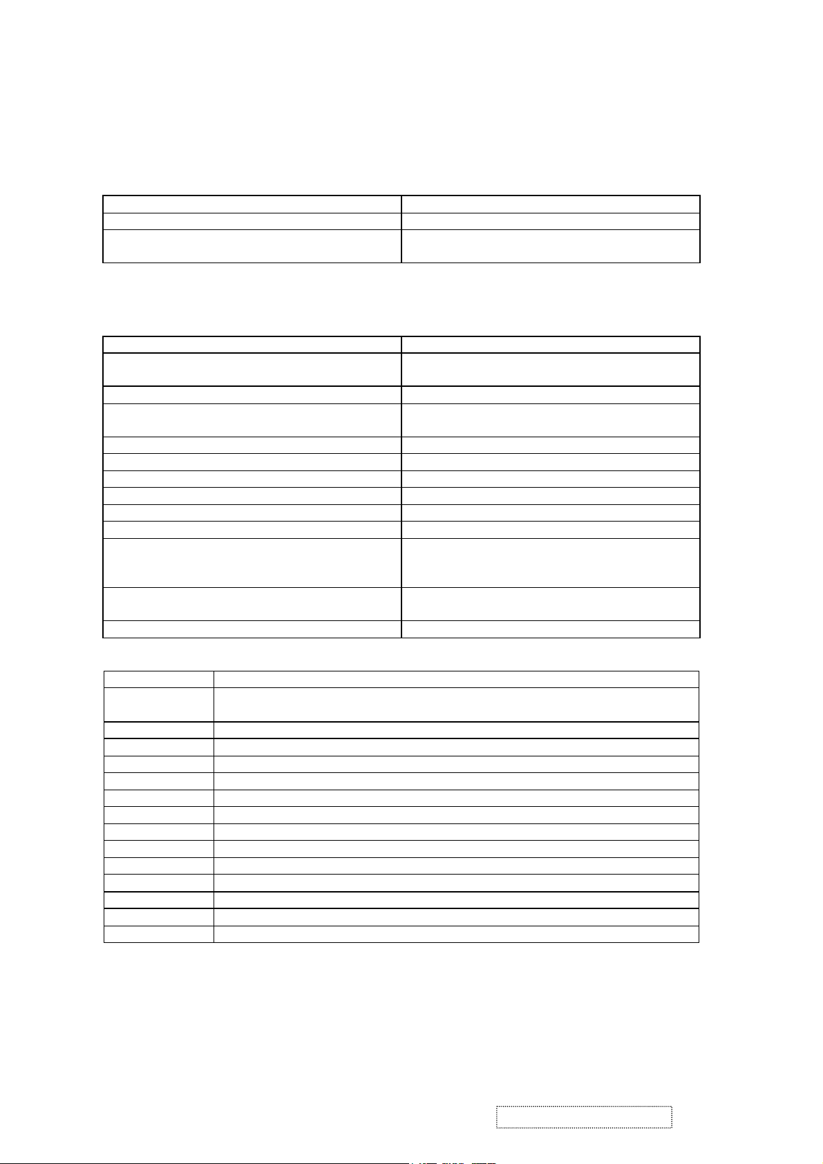
SCGENERAL REQUIREMENTS
General Specifications
Test Resolution & Frequency “1024 X 768” @ 60Hz
Test Image Size Full Size
Contrast and Brightness Controls Factory Default: Contrast = 70%, Brightness =
100%
SIGNAL INTERFACE
Video Interface
Analog Input DB-15 (Analog)
Video Cable Strain Relief Equal to twice the weight of the monitor for five
Video Cable Connector DB-15 Pinout Compliant DDC 1/2B.
Video Signals Video RGB (Analog)
Video Impedance 75 Ohms (Analog)
Maximum PC Video Signal 950 mV with no damage to monitor
Maximum Mac Video Signal 1250 mV with no damage to monitor
Sync Signals TTL
DDC 1/2B Compliant with Revision 1.3
Sync Compatibility Separate Sync
Video Compatibility Shall be compatible with all PC type computers,
Resolution Compatibility 640 x 350, 640 x 480, 720 x 400 (640 x 400), 800
Exclusions Not compatible with interlaced video.
Table 3.1: 15 pin D-sub connector pin assignment
Pin Number Pin Function
1 Red video input
2 Green video input
3 Blue video input
4 No Connection
5 Ground
6 Red video ground
7 Green video ground
8 Blue video ground
9 +5V
10 Ground
11 No connection
12 (SDA)
13 Horizontal sync (Composite sync)
14 Vertical sync
15 (SCL)
minutes.
Separate
Macintosh computers, and after market video
cards.
x 600, 832 x 624, 1024 x 768,
ViewSonic Corporation Confidential
3
-
Do Not Copy VE510s/b-1
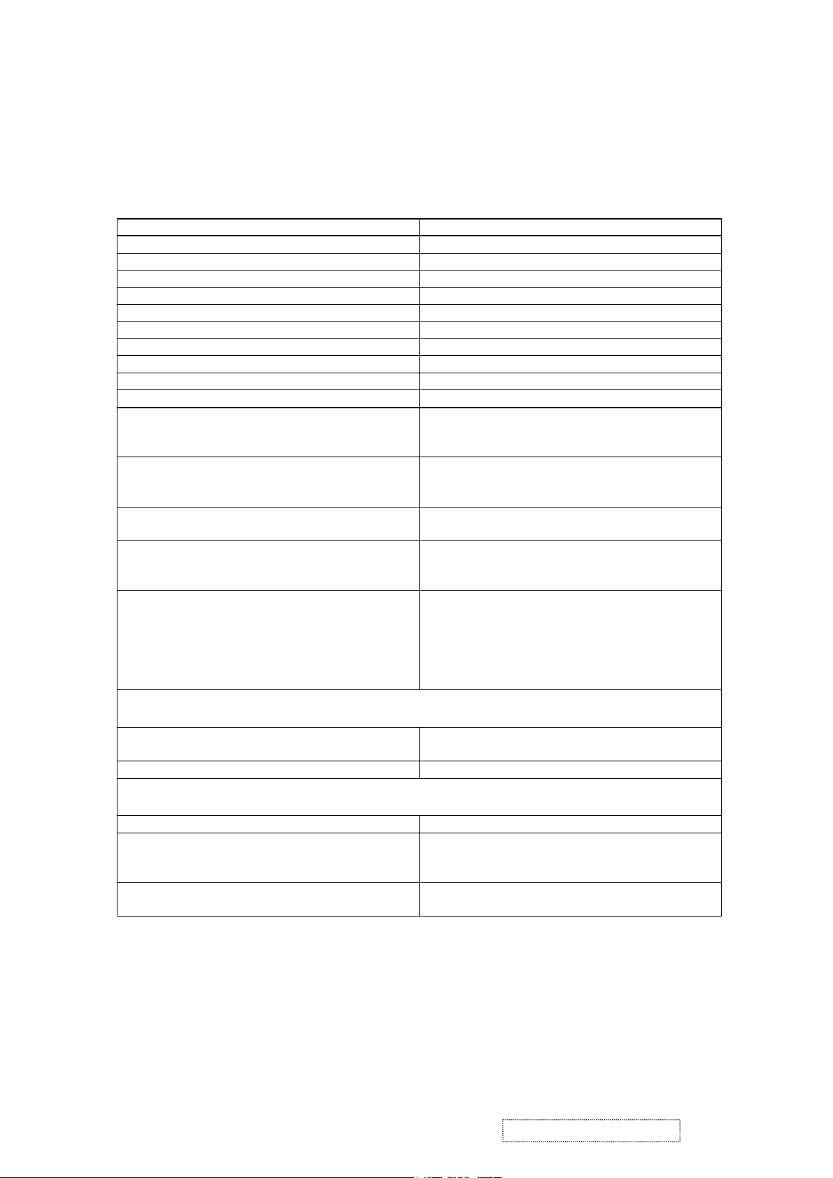
POWER
Power Supply
Internal Power Supply Yes.
Input Voltage Range 90 TO 264 VAC
Input Frequency Range 47 TO 63 HERTZ
Short Circuit Protection Output can be shorted without damage.
Over Current Protection 0.8 A typical at 265 VDC, 265 or 187VAC
Leakage Current 3.5mA (Max) at 254VAC / 60Hz
EFFICIENCY 65 % typical at 115VAC Full Load
Fuse Internal and not user replaceable
Power Dissipation 34 Watts (typ)
Max Input AC Current 1.2 Arms @ 90VAC, 0.6 Arms @180VAC
INRUSH CURRENT (COLD START) 60 A @ 120VAC, 80 A(max) @220VAC
Power Supply Cold Start Shall start and function properly when under full
load, with all combinations of input voltage, input
frequency, and operating temperature.
Power Supply Transient Immunity Shall be able to withstand an ANSI/IEEE C62.41-
1980 6000V 200 ampere ring wave transient test
with no damage.
Power Supply Line Surge Immunity Shall be able to withstand 1.5 times nominal line
voltage for one cycle with no damage.
Power Supply Missing Cycle Immunity Shall be able to function properly, without reset or
visible screen artifacts, when ½ cycle of AC power
is randomly missing at nominal input.
Power Supply Acoustics The power supply shall not produce audible noise
that would be detectable by the user. Audible shall
defined to be in compliance with ISO 7779 (DIN
EN27779:1991) Noise measurements of machines
acoustics. Power Switch noise shall not be
considered.
Power Interface
US Type Power Cable Separate 3-prong NEMA 5-15P type plug. Length
= 1.8m. Color = BLACK
European Type Power Cable Schuko CEE7 -7. Length = 1.8m, Color = BLACK
Power Saving Operation
Method VESA DPMS Signaling
Power Consumption
ON Mode <50 W (max) / 30 W (typ)
ACTIVE OFF < 1W
Recovery Time ON Mode = N/A
ACTIVE OFF < 3 SEC
ViewSonic Corporation Confidential
4
-
Do Not Copy VE510s/b-1

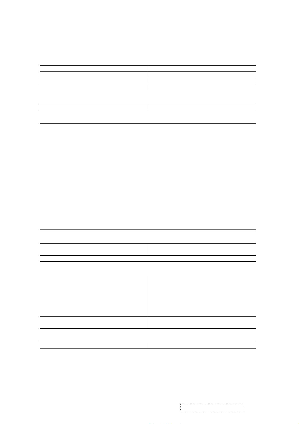
FRONT PANEL CONTROLS AND INDICATORS
Front Panel Hardware Controls
Power Switch (Front Head) Power Control, soft Power Switch.
Power LED (Front Head) Green – ON
Orange – Active Off
Dark = Soft Power Switch OFF
Front Panel Controls (Head)
Button 1
Down arrow button
Up arrow button
Button 2
Power
Note: Power Button, Button 1, Button 2, must be
one-shot logic operation. (i.e. there should be no
cycling)
Reaction Time OSD must fully appear within 0.5s after pushing
Button 1.
Short Cuts Function from the button(s)
[1] Main Menu
[2] Auto Image Adjust.
[DOWN] or [UP] arrow to immediately activate Contrast menu. It should be
change to Brightness OSD by push button [2].
[DOWN] + [UP] arrows recall Contrast or Brightness while in the Contrast
or Brightness adjustment, or recall both of
Contrast and Brightness when the OSD is not open.
[1] + [2] toggle 720x400 and 640x400 mode when input
720x400 or 640x400 mode.
[1] + [Down] + [Up] White Balance. (Not show on user’s guide)
[1] + [Down] Power Lock
(see section “OSD Lock short cuts function for the
buttons” in 5.4)
ViewSonic Corporation Confidential
5
-
Do Not Copy VE510s/b-1
ELECTRICAL REQUIREMENTS
Horizontal / Vertical Frequency
Horizontal Frequency 30 – 62 KHZ
Vertical Refresh Rate 50 – 85 HZ.
Maximum Pixel Clock 80 MHz
Sync Polarity Independent of sync polarity.
Primary Presets
Primary Preset “1024 X 768” @ 60Hz
Look up table timing
<<Analog>>
1. 640 x 350 @ 70Hz, 31.5kHz
2. 640 x 480 @ 60Hz, 31.5kHz
3. 640 x 480 @ 67Hz, 35.0kHz
4. 640 x 480 @ 75Hz, 37.5kHz
5. 640 x 480 @ 72Hz, 37.9kHz
6. 640 x 480 @ 85Hz, 43.27kHz
7. 720 x 400 @ 70Hz, 31.5kHz
8. 800 x 600 @ 56Hz, 35.1kHz
9. 800 x 600 @ 60Hz, 37.9kHz
10. 800 x 600 @ 75Hz, 46.9kHz
11. 800 x 600 @ 72Hz, 48.1kHz
12. 800 x 600 @ 85Hz, 53.7kHz
13. 832 x 624 @ 75Hz, 49.7kHz
14. 1024 x 768 @ 60Hz, 48.4kHz
15. 1024 x 768 @ 70Hz, 56.5kHz
16. 1024 x 768 @ 72Hz, 58.1kHz
17. 1024 x 768 @ 75Hz, 60.0kHz
User Presets
Number of User Presets (recognized timings)
10 presets total in FIFO configuration.
Available
Changing Modes
Maximum Mode Change Blank Time, for image
stability. Note:
1) Excluding “Auto Adjust” time
3 seconds (Max)
1 seconds (Typ) for recognized timings
1-2 seconds (Typ) for unrecognized timing
2) Under DOS mode (640 x 350, 720 x 400 & 640
x 400), there is no “Auto Adjust” feature.
3) The monitor needs to do “Auto Adjust” the first
time a new mode is detected.
Mode Change Image The image shall blank while the monitor changes
modes.
GTF
GTF N/A
ViewSonic Corporation Confidential
6
-
Do Not Copy VE510s/b-1
LCD Panel
Panel Characteristics:
Panel Type “GBM GB150XQQ3-A001
Type TN TYPE
Active Size 304.1 (H) x 228.1 (V)
Pixel Arrangement RGB Vertical Stripe
Pixel Pitch 0.297 mm
GLASS TREATMENT Anti Glare (Hard coating 3H)
# OF BACKLIGHTS 2 CCFL edge-light (1 top / 1 bottom)
BACKLIGHT LIFE 30,000 Hours (Min)
Panel Performance
Luminance –
Condition:
250 cd/m2 (typ after 30 minute warmup)
200 cd/m2 (min after 30 minute warmup)
CT = 6500K, Contrast = Max, Brightness = Max
Brightness Uniformity 70% Entire Area (MAX)
Contrast Ratio 400:1 (typ), 300:1 (min)
Color Depth 16 million colors (6 bit FRC panel)
Viewing Angle (Horizontal) 120 deg @ CR>10, 140 deg @ CR>5
VIEWING ANGLE (VERTICAL) 90 deg @ CR>10, 100 deg @ CR>5
Response Time
10%-90% @ Ta=25°C
16 ms (Tr= 4ms, Tf = 12 ms) (min)
30 ms (Tr= 10 ms, Tf = 20 ms) (typ)
Panel Defects Please see Panel Quality Specifications.
ViewSonic Corporation Confidential
7
-
Do Not Copy VE510s/b-1

IMAGE PERFORMANCE
Factory Defaults
Contrast 70%
Brightness 100%
Color Temperature 6500K
Sharpness 75%
OSD H. Position 50%
OSD V. Position 50%
OSD Time Out 15 Sec
OSD Background On
Resolution Notice Enabled
720x400/640x400 720x400
Display Size
Horizontal Display Size, Primary Preset Full Screen
Vertical Display Size, Primary Preset Full Screen
Saturation
Contrast = Default
Brightness = Default
TEST PATTERN = 32-GRAY
Contrast = 100%
Brightness = 100%
Test pattern = 16-gray
No visible saturation
4-level saturation
Preset Color Temperatures
Preset 1 9300K CCT(typ)=9300K
(Wx=0.283+/-0.02, Wy=0.298+/- 0.02)
CCT(Max)=13100K,
CCT(Min)=7300K
Preset 2 6500K (Primary) CCT(typ)=6500K
(Wx=0.313+/-0.02,Wy=0.329+/-0.02)
CCT(Max)=8000K,
CCT(Min)=5500K
Preset 3 CCT(typ)=5400K
(Wx=0.332+/-0.02, Wy=0.349+/-0.02)
CCT(Max)=6400K,
CCT(Min)=4600K
Preset Color Temperature Adjustability Each color preset shall be adjustable. Red, Green,
and Blue shall be individually controlled.
Video Cards Compatibility
Peaking Performance Peaking is not adjustable.
Raster Artifacts
Video Artifacts No visible streaking, sag, or smearing artifacts
when driven by the specified video cards in the
primary mode and after user adjustment to best
condition.
Power Supply, and Grounding Artifacts No visible artifacts in any specified video mode
within the horizontal or vertical frequency range of
the monitor
Temperature Drift Image shall not drift or lose fine-tune adjustment.
ViewSonic Corporation Confidential
8
-
Do Not Copy VE510s/b-1
3. Front Panel Function Control Description
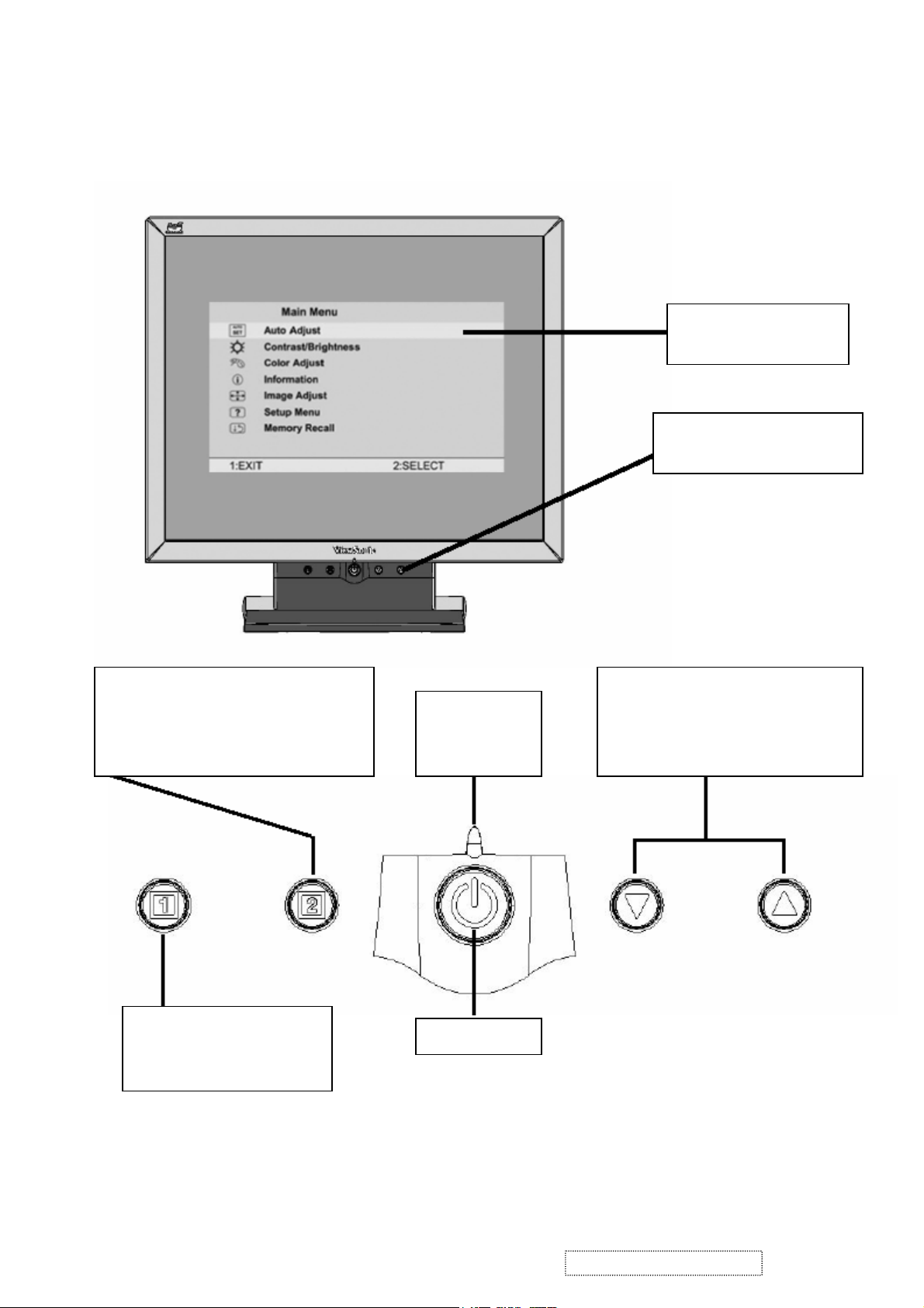
Main Menu
With On V i ew controls
Front Control Panel
shown below in detail
Displays the control screen for the
highlighted control. Also toggles
between two controls on some screens.
Also a shortcut to auto image adjust
Displays the Main Menu or
exits the control screen
and saves adjustments.
Scrolls through menu options and
Power light
Green = ON
Orange=power
adjusts the displayed control.
Also a shortcut to display the
Contrast adjustment control screen.
Power On / Off
ViewSonic Corporation Confidential
9
-
Do Not Copy VE510s/b-1
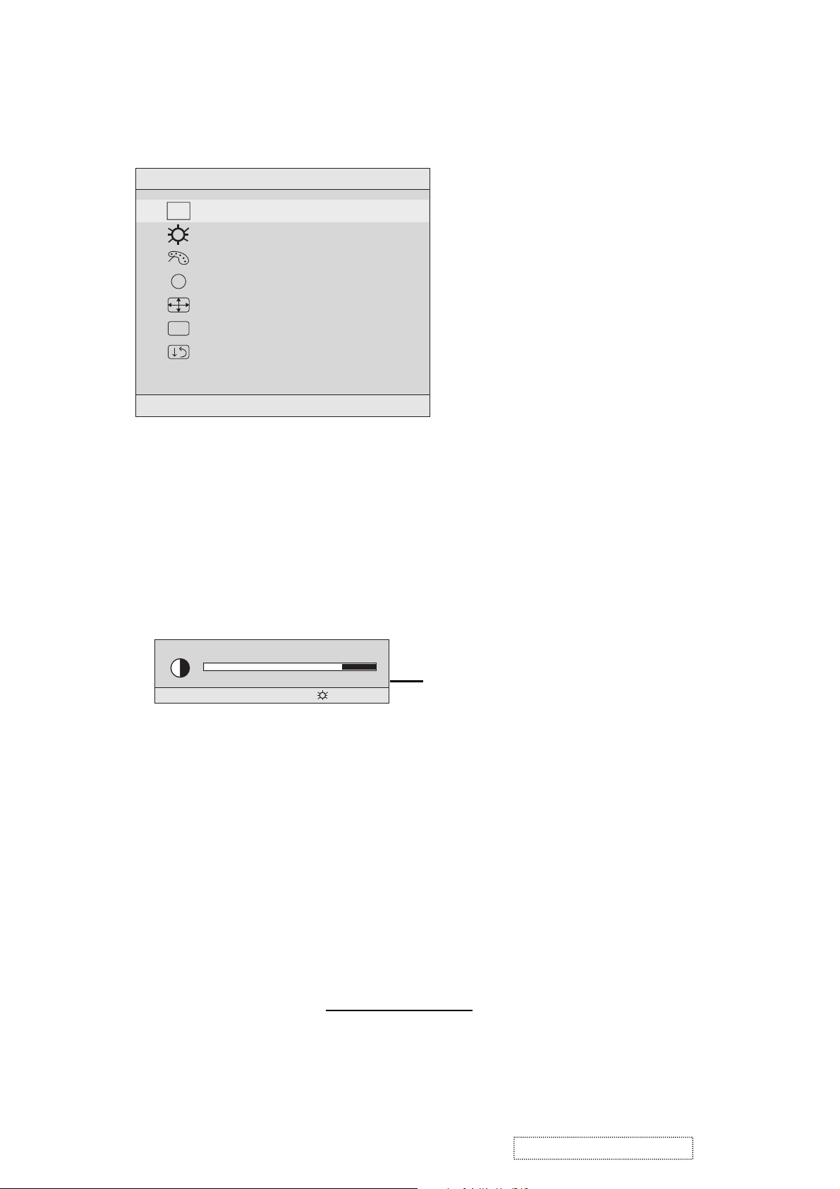
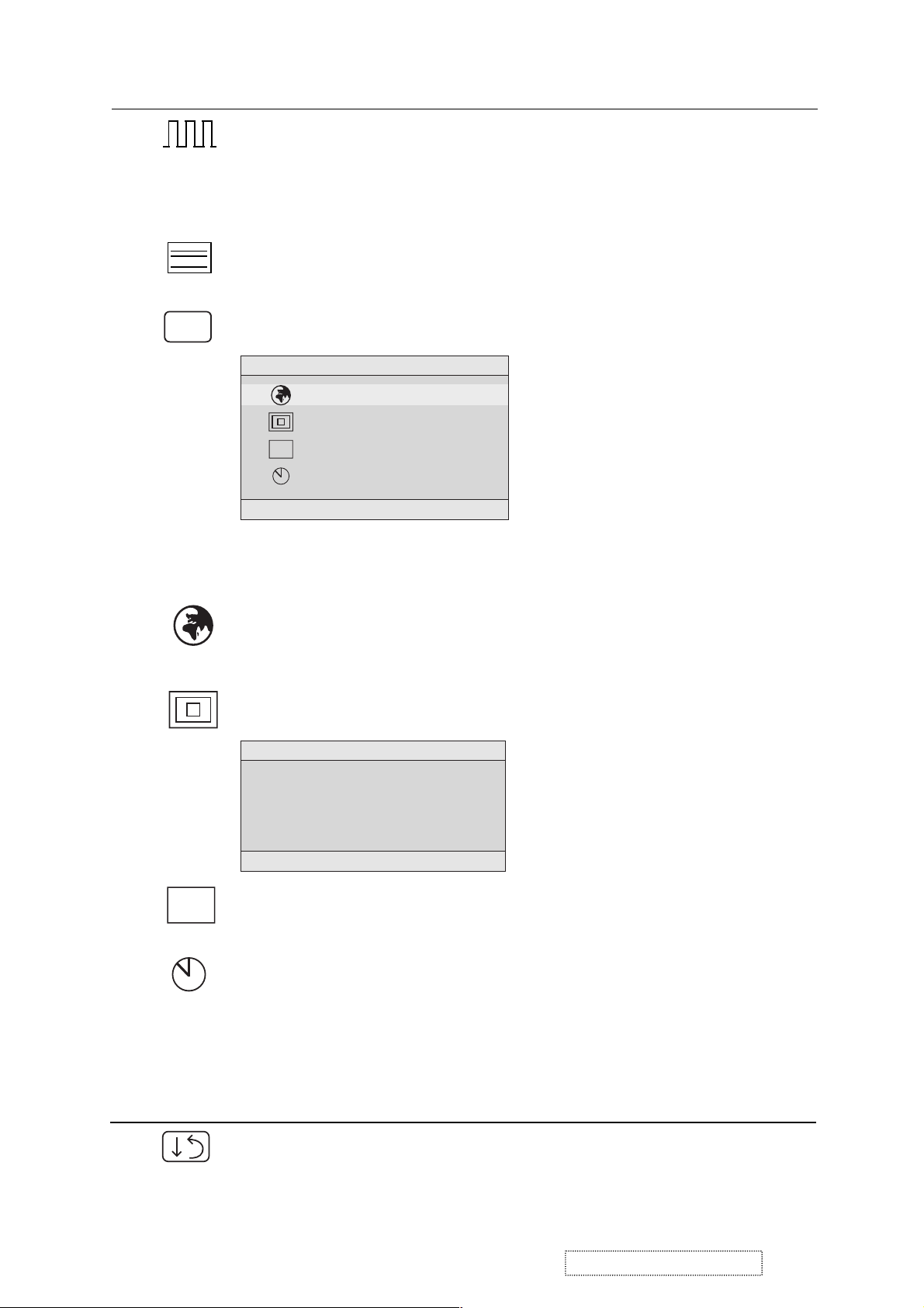
Do the following to adjust the screen image:
1
To display the Main Menu, press button [1].
Main Menu
AUTO
SET
?
1:EXIT 2:SELECT
Auto Adjust
Contrast/Brightness
Color Adjust
Information
i
Image Adjust
Setup Menu
Memory Recall
NOTE: All OnView menus and adjustment screens disappear automatically
after about 15 seconds. This time period is adjustable through the Setup
menu and the OSD timeout control described on page 11.
2
To highlight a control you want to adjust, press I or J to scroll up or down
the Main Menu.
3
To select the highlighted control, press button [2]. A control screen appears
like the example shown below.
Contrast
1:EXIT 2: Brightness
4
To adjust the control, press the up I or down J buttons.
5
To save the adjustments and exit the menu, press button [1] twice.
The following tips may help you optimize your display:
The line at the
bottom of the
screen tells you
what you can do
next: Exit or Select
the control that is
highlighted.
• Adjust your computer's graphic card so that it outputs a video signal 1024 x
768 @ 60 Hz to the LCD display. (Look for instructions on “changing the
refresh rate” in your graphic card's user guide.)
• If necessary, make small adjustments using H. POSITION and V. POSITION
until the screen image is completely visible
. (The black border around the
edge of the screen should barely touch the illuminated “active area” of the
LCD display.)
ViewSonic Corporation Confidential
10
-
Do Not Copy VE510s/b-1

Main Menu Controls
Adjust the menu items shown below by using the up Iand down Jbuttons.
Control Explanation
Auto Adjust
automatically sizes, centers, and fine tunes the
video signal to eliminate waviness and distortion.
Press the [2] button to obtain a sharper image.
NOTE
: Auto Adjust works with most common video cards. If
this function does not work on your LCD display, then lower the
video refresh rate to 60 Hz and set the resolution to its pre-set
value.
Contrast
adjusts the difference between the image background
(black level) and the foreground (white level).
Brightness
Color Adjust
adjusts background black level of the screen image.
provides several color options: preset color
temperatures and User which allows you to adjust red (R), green
(G), and blue (B). The factory setting for this product is 6500K
(6500 Kelvin).
sRGB
— sRGB is quickly becoming the industry standard for
color management, with support being included in many of the
latest applications. Enabling this setting allows the LCD display
to more accurately display colors the way they were originally
intended. Enabling the sRGB setting will cause the Contrast and
Brightness adjustments to be disabled.
9300K
— Adds blue to the screen image for cooler white (used
in most office settings with fluorescent lighting).
6500K
— Adds red to the screen image for warmer white and
richer red.
5400K
ViewSonic Corporation Confidential
— Adds green to the screen image for a darker color.
11
-
Do Not Copy VE510s/b-1
Control Explanation
User Color
and blue (B)
To select color (R, G or B) press button [2].
1
To adjust selected color, press ▲ or ▼.
2
Important
— Individual adjustments for red (R), green (G),
.
: If you select RECALL from the Main Menu when
the product is set to a Preset Timing Mode, colors return to the
6500K factory preset.
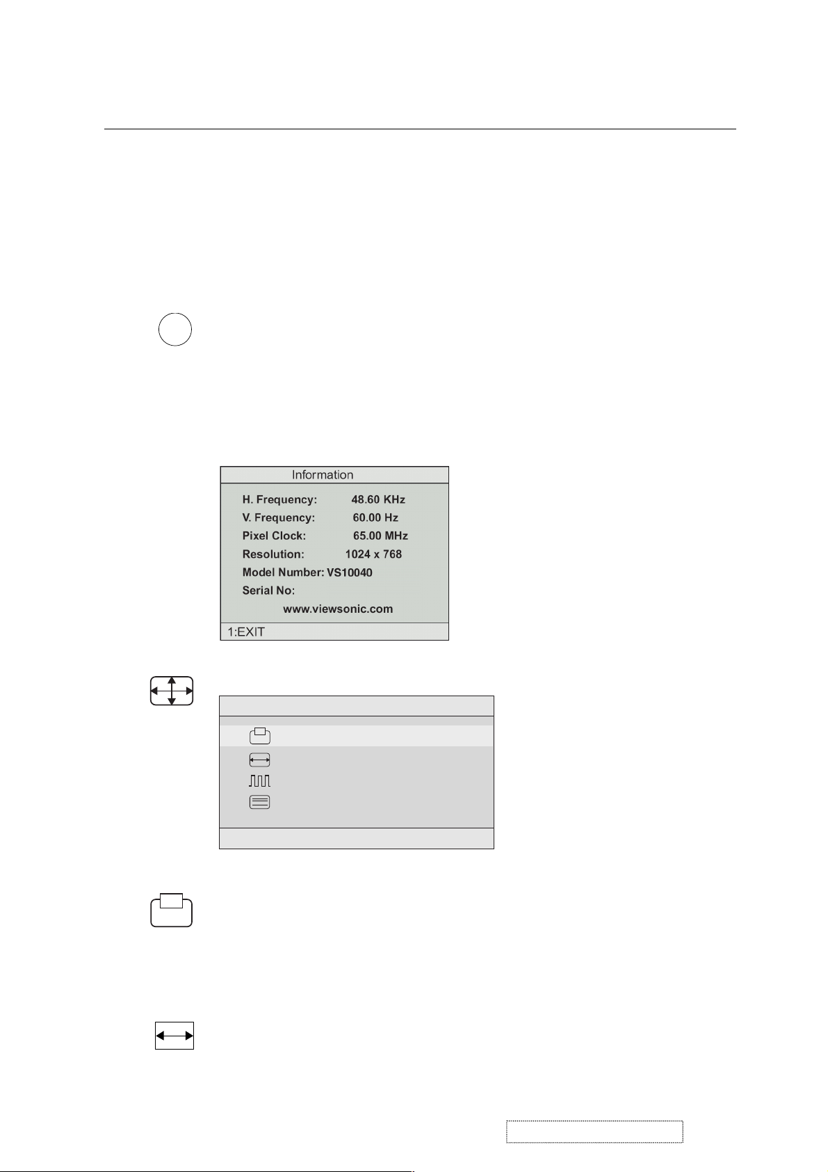
i
Information
coming from the graphics card in your computer. See your
displays the timing mode (video signal input)
graphic card’s user guide for instructions on changing the
resolution and refresh rate (vertical frequency).
VESA 1024 x 768 @ 60 Hz (recommended) means that the
resolution is 1024 x 768 and the refresh rate is 60 Hertz.
Image Adjust
Image Adjust
H./V. Position
H. Size
Fine Tune
Sharpness
1:EXIT 2:SELECT
The Image Adjust controls are explained below:
H./V. Position
adjusts horizontal and vertical position of the
screen image. You can toggle between Horizontal and Vertical
by pressing button [2]. Horizontal moves the screen image to
the left or to the right. Vertical moves the screen image up and
down.
H. Size
NOTE:
(Horizontal Size) adjusts the width of the screen image.
Vertical size is automatic with your LCD display.
ViewSonic Corporation Confidential
12
-
Do Not Copy VE510s/b-1
Control Explanation
Fine Tune sharpens focus by aligning the illuminated text and/
or graphic characters.
NOTE:TrytheAuto Adjust before using the Fine
Tune control.
?
Sharpness
adjusts the clarity and focus of the screen image.
Setup Menu displays the menu shown below.
Setup Menu
Language Select
Resolution Notifier
OSD Position
OSD
OSD Timeout
1:EXIT 2:SELECT
The Setup Menu controls are explained below.
L
anguage
Select allows you to choose the language used in
the menus and control screens.
Resolution Notice
Resolution Notice
For best picture quality
change the resolution to
1024 x 768
1:EXIT 2:DISABLE
OSD
OSD Position
and control screens.
OSD Timeout
screen is displayed. For example, with a “15 second” setting, if
a control is not pushed within 15 seconds, the display screen
disappears.
Control Explanation
Memory Recall
settings if the display is operating in a factory Preset Timing
Mode listed in this user guide.
advises the optimal resolution to use.
allows you to move the on-screen display menus
sets the length of time an on-screen display
returns adjustments to the original factory
ViewSonic Corporation Confidential
13
-
Do Not Copy VE510s/b-1
4. Circuit Description
1. Outline
1.1 Power On/Off, 2Enter button (INPUT SELECT) , up arrow- button, down arrow button, 1MENU button,
button on the front panel.
1.2 Video signal connector and AC-IN jack are located on the back side of the cabinet.
1.3 OSD menu includes the following function;
Auto Image Adjust (only active under analog input)
Contrast/Brightness
Audio Adjust
Color Adjust
Information
Manual Image Adjust
Setup Menu
Memory Recall
1.4 Contrast and Brightness can be directly controlled with UP / DOWN key.
2. CONNECTORS
2.1 AC inlet : CEE22 typed connector
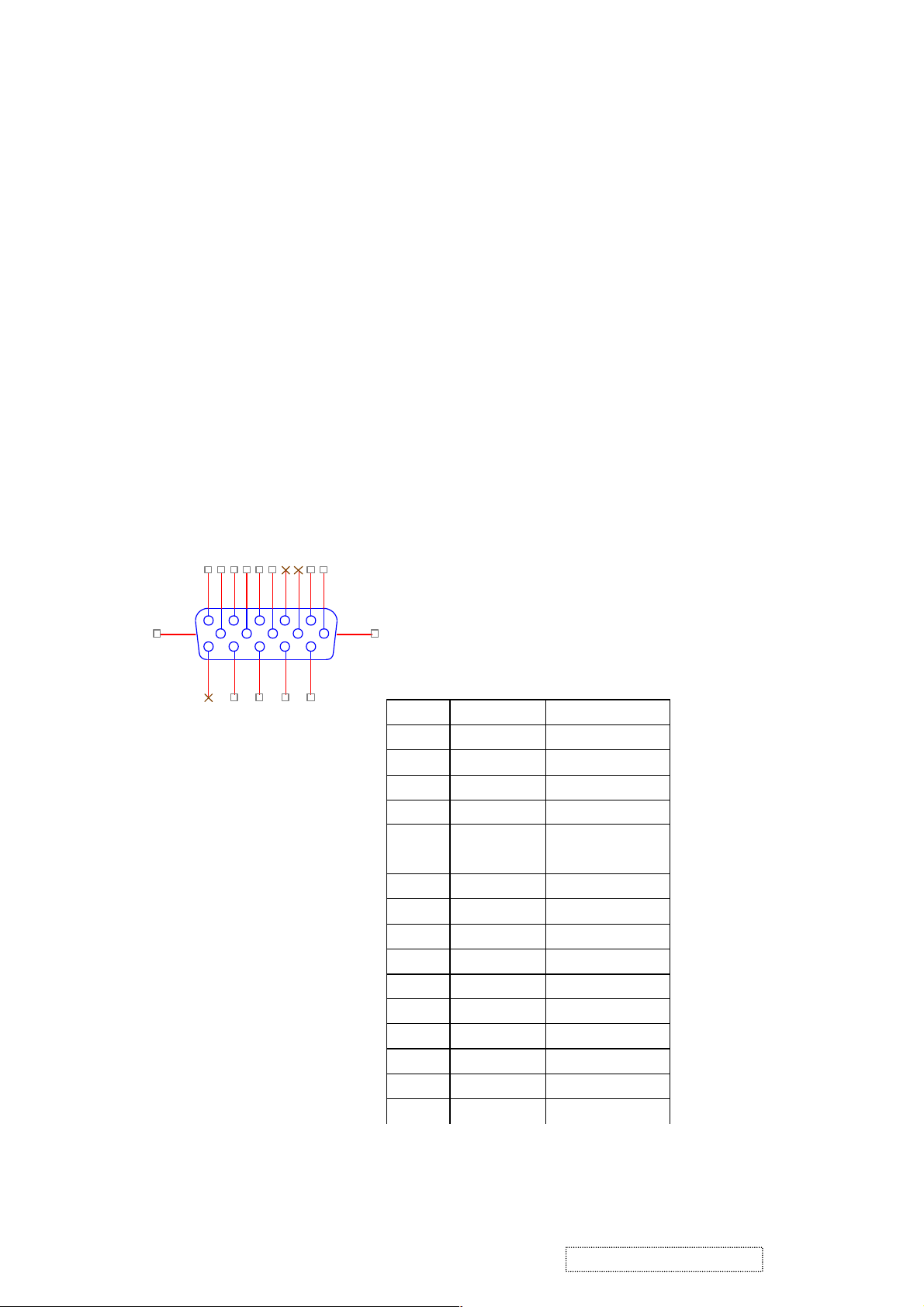
2.2 Video signal connector for analog input: 15P Mini D-Sub
162738495
16 17
11
12
13
14
CN6
10
DB15HD
15
PIN MNEMONI
1 RV Red Video
2 GV Green Video
3 BV Blue Video
4 NC None
5 GND Ground (DDC
6 RG Red GND
7 GG Green GND
8 BG Blue GND
9 +5V +5V (for DDC)
10 SG Sync GND
11 NC None
12 SDA DDC Data
13 HS Horizontal Sync
14 VS Vertical Sync
15 SCL DDC Clock
SIGNAL
return)
ViewSonic Corporation Confidential
14
-
Do Not Copy VE510s/b-1
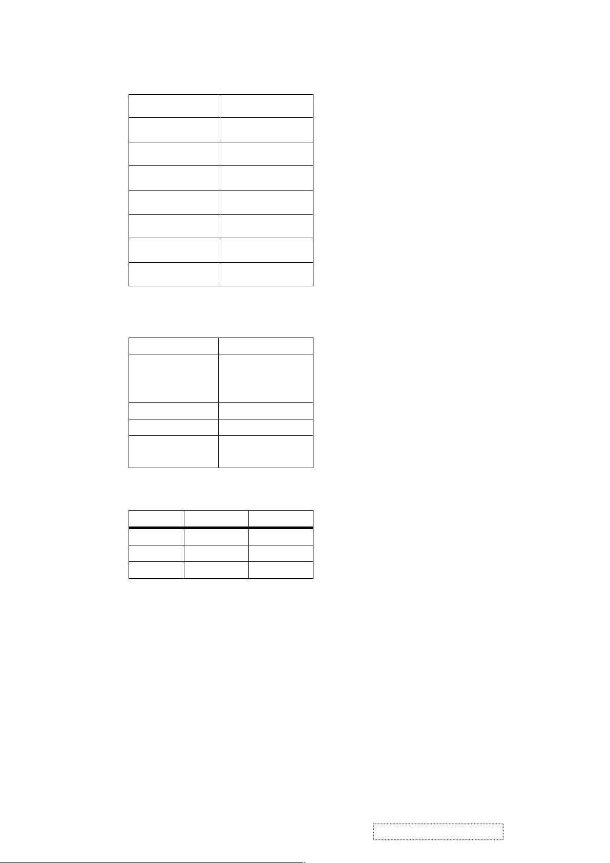
3. ELECTRICAL SPECIFICATIONS
3.1 Standard conditions
Display Area
Video Signal
Contrast
Brightness
Ambient
Input
Warming up
Display
3.2 POWER
3.2.1 Power supply
Input Voltage 90 -240 ~Volts
Power Frequency
Input current
Inrush current 90A(max.) at 230Vac
Power consumption 30Watt
Output Voltage @0-4.8A load 12Vdc
3.2.2 Power Management
State Power Indicator
304 x 228 mm
0.7 Vpp
Max.
Max.
20 +/- 5 °C
AC
> 30 min
1024 x 768
50/ 60 Hz +/-3Hz
<1.5Arms @ 90Vac
<0.75Arms@265Vac
+/-5%
On 30Watt Green
Standby <1Watt Amber
Off <1Watt
3.3 Acceptable timing
Off
If your timing is within following specification, this LCD display can automatically function with a certain
position.
Horizontal: Sync frequency : 30~82 kHz
Vertical: Sync frequency : 56~75Hz
3.4 Signal level and input impedance
3.4.1 Video Signal level: 0.7 Vp-p Video signal.
3.4.2 Sync Signal level
H/V Separate : TTL level
3.4.3 Input impedance
Video input : 75 ohms
Sync input : > 1 k ohms
ViewSonic Corporation Confidential
15
-
Do Not Copy VE510s/b-1
 Loading...