


Service Manual
ViewSonic VE510+-1
Model No.VLCDS23587-2W
15” Color TFT LCD Display
ViewSonic
(VE510+-1_SM_546 - Rev. 2a – Dec 2002)
381 Brea Canyon Road, Walnut, California 91789 USA - (800) 888-8583
Copyright
Copyright © 2002 by ViewSonic Corporation. All rights reserved. No part of this
publication may be reproduced, transmitted, transcribed, stored in a retrieval system,
or translated into any language or computer language, in any form or by any means,
electronic, mechanical, magnetic, optical, chemical, manual or otherwise, without the
prior written permission of ViewSonic Corporation.
Disclaimer
ViewSonic makes no representations or warranties, either expressed or implied, with
respect to the contents hereof and specifically disclaims any warranty of
merchantability or fitness for any particular purpose. Further, ViewSonic reserves the
right to revise this publication and to make changes from time to time in the contents
hereof without obligation of ViewSonic to notify any person of such revision or
changes.
Trademarks
ViewSonic is a registered trademark of ViewSonic Corporation. All other trademarks
used within this document are the property of their respective owners.
Revision History
Revision Date Description Approval
1a 07/29/02 Initial Release DCN-2255 K.Yang
1b 11/04/02 Revise DCN-2255 C.Shen
2a 12/18/02 Major Re-Write DCN-2255 C.Shen
ViewSonic Corporation
i
Confidential --Do Not Copy VE510+-1

TABLE OF CONTENT
Chapter 1 Precautions and Notices…………………………………………1
Chapter 2 Specification…………………………………………………….....3
2-1 Features……………………………………………………….. 3
2-2 General Specification………………………………………….4
2-3 Factory Preset Timing…………………………………………5
2-4 D-Sub connector Pin Assignment…………………………...6
Chapter 3 Disassembly / Assembly Instructions…………………………7
Chapter 4 Electronic Circuit Description…………………………………..9
4-1 Block Diagram………………………………………………….9
4-2 Main Board I/O Connections………………………………….11
4-3 Inverter Board I/O Connections……………………………...13
4-4 Theory of Circuit Operation…………………………………..13
Chapter 5 Adjustment…………………………………………………………29
Chapter 6 Troubleshooting Flow Chart……………………...…………….32
6-1 Figures of Wave Form………………………………………32
6-2 Troubleshooting Flow Chart………………………………..35
Chapter 7 Schematics Diagrams……………………………………………39
Chapter 8 PCB Layout…………………………………………………...……43
Chapter 9 Exploded Diagram and Mechanical Parts List………….…...45
Chapter 10 Recommended Spare Parts List………..………………….....47
Chapter 11 Complete Parts List……………………………………………..48
Appendix
Reader's Responses
ViewSonic Corporation
ii
Confidential --Do Not Copy VE510+-1

1. Precautions and Notices
Prior to using this manual, please ensure that you have carefully followed all
the procedures outlined in the user manual for this product.
Read all of these instructions.
Save these instructions for later use.
Follow all warnings and instructions marked on the product.
Do not use this product near water.
This display should be installed on a solid horizontal base.
When cleaning, use only a neutral detergent cleaner with a soft damp cloth.
Do not spray with liquid or aerosol cleaners.
Do not expose this display to direct sunlight or heat. Hot air may cause
damage to the cabinet and other parts.
Adequate ventilation must be maintained to ensure reliable and continued
operation and to protect the display from overheating. Do not block ventilation
slots and openings with objects or install the display in a place where
ventilation may be hindered.
Do not install this display near a motor or transformer where strong
magnetism is generated. Images on the display will become distorted and
the color irregular.
Do not allow metal pieces or objects of any kind fall into the display from
ventilation holes.
Slots and openings in the cabinet and the back or bottom are provided for
ventilation, to ensure reliable operation of the product and to protect it from
overheating, those openings must not be blocked or covered. The openings
should never be blocked by placing the product on a bed, sofa, rug, or other
similar surface. This product should never be placed near or over a radiator or
heat register. This product should not be placed in a built-in installation unless
proper ventilation is provided.
ViewSonic Corporation
1
Confidential --Do Not Copy VE510+-1
FCC Statement
This equipment has been tested and found to comply with the limits of Class B digital
device, pursuant to part 15 of the FCC Rules. These limits are designed to provide
reasonable protection against harmful interference in a residential installation. This
equipment generates uses and can radiate radio frequency energy, and for if not
installed and used in accordance with the instructions, may cause harmful
interference to radio communication. However, there is no guarantee that the
interference will not occur in a particular installation. If this equipment does cause
unacceptable interference to radio or television reception, which can be determined
by turning the equipment off and on, the user is encouraged to try to correct the
interference by one or more of following measures
Reorient or relocate the receiving antenna.
Increase the separation between equipment and receiver.
Use a different power outlet for the monitor and receiver.
Consult the dealer or an experienced radio/TV technician for help.
᧶
FCC Warning
To assure continued FCC compliance, the user must use a grounded power supply
cord and the provided shielded video interface cable with bonded ferrite cores. Also,
unauthorized changes or modifications to ViewSonic products will void the usercs
warranty to operate this device. Thus ViewSonic will not be held responsible for the
product and its safety.
CE Certification
This device complies with the requirements of the ECC directive
89/3366/EEC with regard to sElectromagnetic compatibility.s
Safety Guidelines
Caution:
listed below for each area
Use a power cable that is properly grounded. Always use the AC cords
᧶
USA
Canada
Germany
Switzerland
Britain
Japan
(UL)
(CSA)
(VDE)
(SEV)
(BASE/BS)
(Electric Appliance Control Act)
In other areas, use AC cord which meets the local safety standards.
ViewSonic Corporation
2
Confidential --Do Not Copy VE510+-1

2. Specification
2-1 Features
VE510+ is a world class TFT LCD analog display monitor that includes the
following features.
1. Digital On Screen Display Controls
User friendly buttons: Mute, VolumeЁ, VolumeЀ, Button1, Down, Up,
Button2, and POWER (Soft Switch), allowing for picture perfect quality.
(Power, Button1, Button2 and Mute button should be one shot logic
operation.)
2. Power Supply Support
Ability to accept voltages from 87~264VAC, thus allowing a full range of
input AC power supply.
3. Power Saving System
This environmental friendly product is able to reduce power consumption
by more than 90% in Active Off Mode.
4. Frequency Range
Monitor can support video standards from VGA to XGA, where Horizontal
Frequency is from 30 to 62 kHz and Vertical Refresh Rate is from 50 to
75Hz.
ViewSonic Corporation
3
Confidential --Do Not Copy VE510+-1
2-2 General Specification
Characteristic Description
LCD Panel Mitsubishi 15.0” AA150XC01, 0.297mm (H/V),
Anti-glare
Maximum Viewing
Angles
Horizontal: 150 degrees @ CR>10
Vertical: 110 degrees @ CR>10
Signal Input VideoΚRGB analog
Sync ΚH.V. Separate Sync.
HorizontalΚ30 to 62KHz
Vertical Κ50 to 75Hz
Connector Analog: 15 Pin Mini D-Sub
Maximum Resolution 1024x768
Video Bandwidth 85 MHz nominal
Display Area 304.1 mm (H) x 228.1 mm (V)
Power Voltage 87~264VAC @ 47~63 Hz
Power Consumption 40W max. (Adaptor plus monitor)
Operating Conditions Temperature : 32 to104 (0 to 40 )
ഘ ഘ
ഒഒ
Humidity : 10% to 90% (no condensation)
Altitude : 0 to +3,000 meters
Storage Conditions Temperature : -4 to +140 (-20 to +60 )
ഘഘ
ഒഒ
Humidity : 10% to 90% (no condensation)
Altitude : 0 to +12,000 meters
Mechanical
Width: 359.0mm / 14.13”
Dimensions
Height: 325.0mm / 12.8”
Depth: 190.5mm / 7.5”
Depth side panel w/o base: 49.0mm / 1.92”
Monitor Weight: 3.3Kg / 7.3 lbs
Package Dimensions Width: 480.0mm / 18.9“
Height: 425.0mm / 16.7”
Depth: 110.0mm / 4.3”
Gross: 5.1Kg (11.2 lbs)
ViewSonic Corporation
4
Confidential --Do Not Copy VE510+-1

2-3 Factory Preset Timing
This timing chart is already preset for the TFT LCD monitors.
Timing Horizontal
Polarity
Horizontal
Frequency
Vertical
Polarity
Vertical
Frequency
VGA 640x350 + 31.47 kHz - 70.09 Hz
VGA 720x400 - 31.46 + 70.08
VGA 640x400 - 31.46 + 70.08
VGA 640x480 - 31.47 - 60.05
VESA 640x480 - 37.86 - 72.81
VESA 640x480 - 37.50 - 75.00
MAC 640x480 Composite 35.00 66.66
VESA 800x600 + 35.15 + 56.25
VESA 800x600 + 37.87 + 60.31
VESA 800x600 + 48.07 + 72.18
VESA 800x600 + 46.87 + 75.00
MAC 832x624 SOG 37.86 72.80
VESA
- 48.36 - 60.00
1024x768
VESA
- 56.47 - 70.06
1024x768
VESA
- 58.03 - 71.91
1024x768
VESA
+ 60.02 + 75.02
1024x768
MAC 1024x768 Composite 60.24 74.92
ViewSonic Corporation
5
Confidential --Do Not Copy VE510+-1

2-4 D-Sub connector Pin Assignment
The TFT LCD analog display monitors use a 15 Pin Mini D-Sub connector as
video input source.
Pin Number Pin Description
1 Red video input
2 Green video input
3 Blue video input
4 Ground
5 Ground
6 R video ground
7 G video ground
8 B video ground
9 +5V
10 Ground
11 No Connection
12 (SDA)
13 Horizontal sync (Composite sync)
14 Vertical sync
15 (SCL)
15
5
0
10
1
1
6
11
ViewSonic Corporation
6
Confidential --Do Not Copy VE510+-1
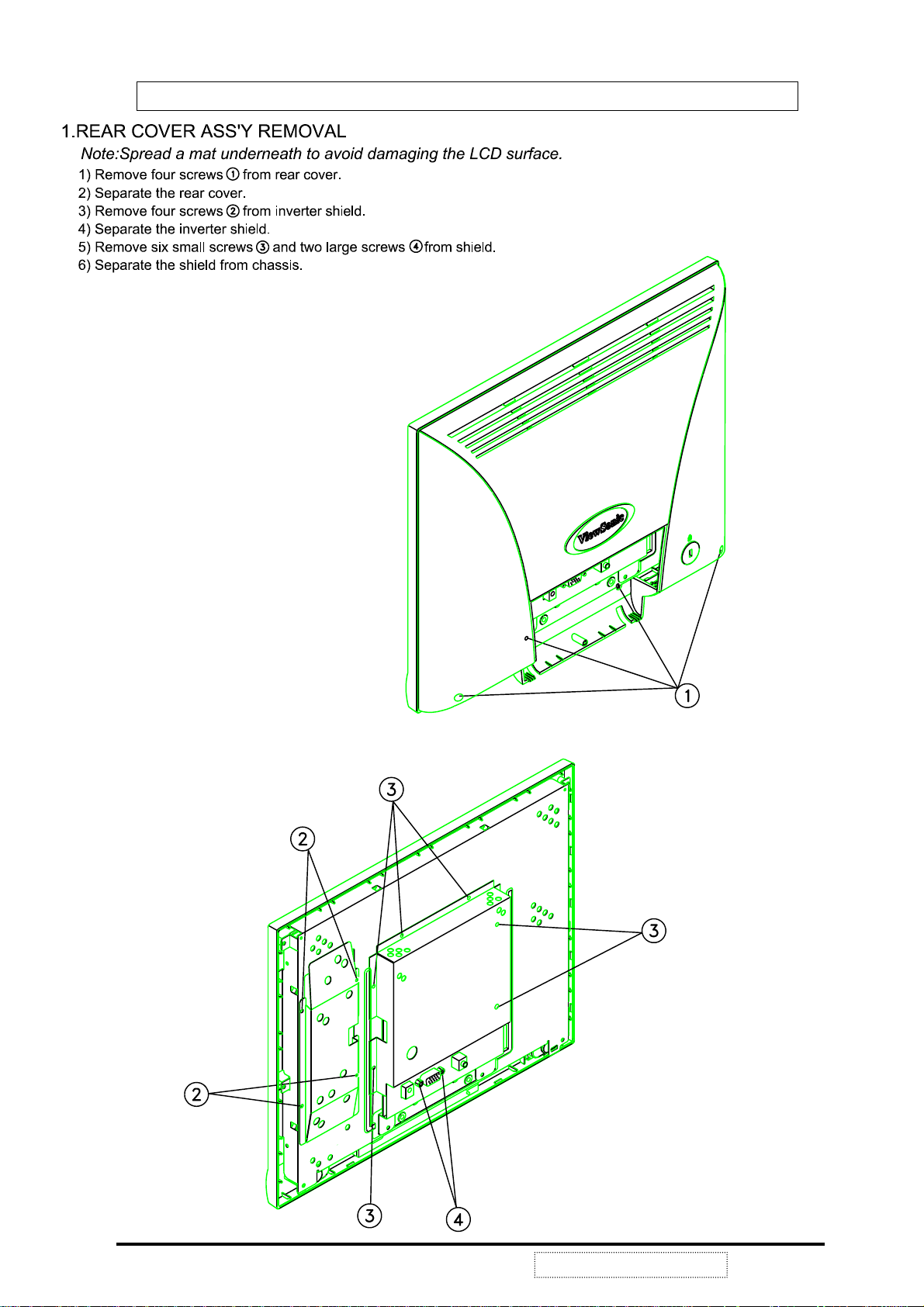
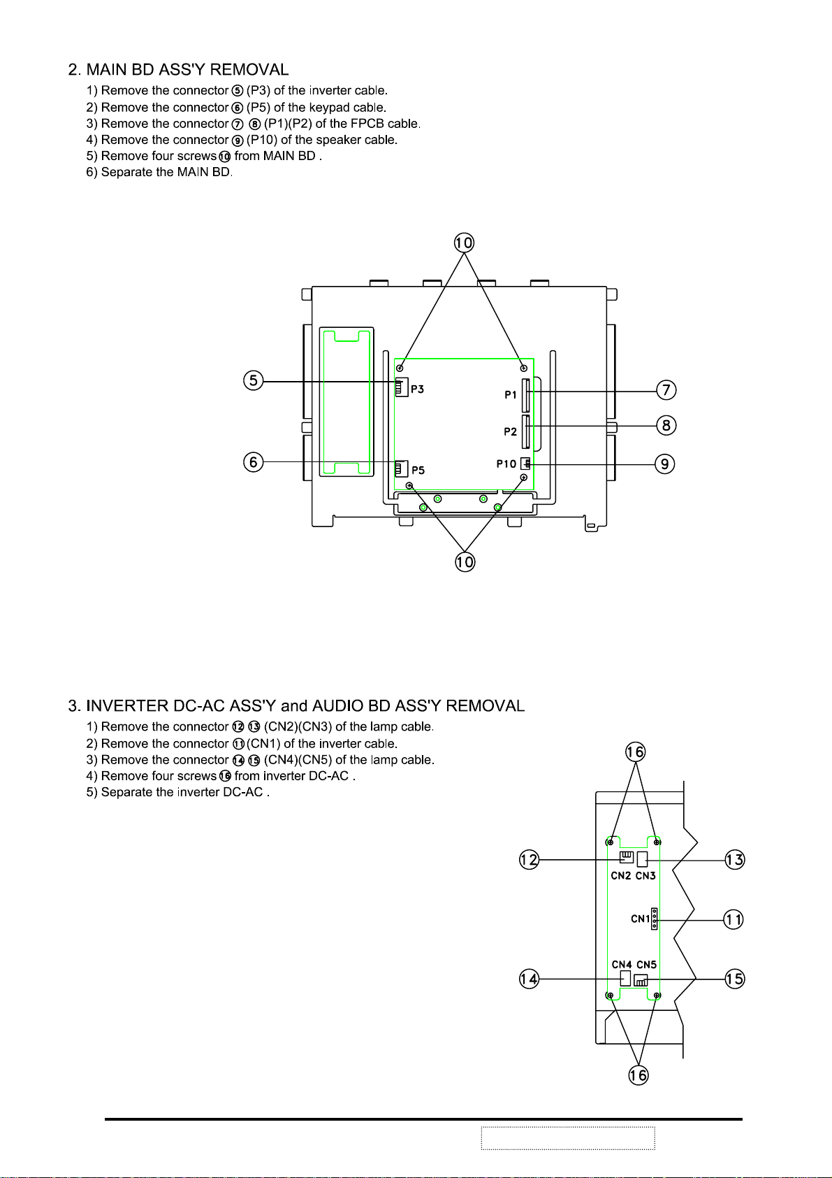
3. Disassembly / Assembly Instructions
ViewSonic Corporation
7
Confidential --Do Not Copy VE510+-1
ViewSonic Corporation
8
Confidential --Do Not Copy VE510+-1
4. Electronic Circuit Description
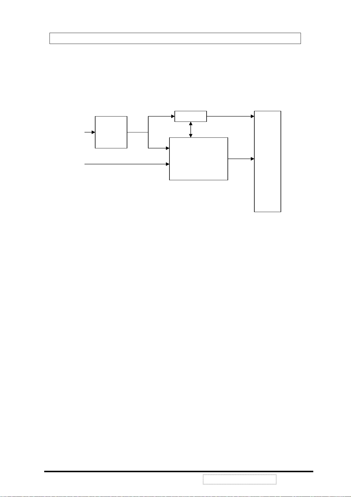
4-1 Block Diagram
C
OMPLETE TFT LCD DISPLAY UNIT
AC Outlet
Video Card
Adaptor
Analog
Signal
12V
12V
Inverter
ControlBrightness
Main Board
VA C
Digital
Signal
TFT
LCD
Panel
ViewSonic Corporation
9
Confidential --Do Not Copy VE510+-1
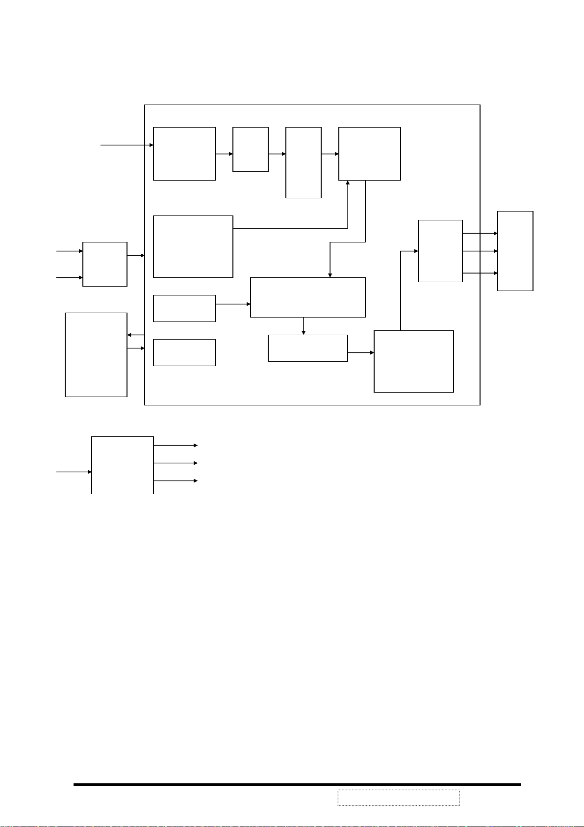
HS
VS
SYNCMOS
SM5964
MCU
R, G, B
Sync
Buffer
U6
HS
VS
Clamp
Video Gain
Video Level
Sync detect
Phase calibration
OSD Generator
MCU port
ADC
MUX
OSD overlay
R, G, B offset
Gamma control
U1 MRT
MASCOT
Scaling
Engine
Dithering
Output control
Output
LCD
Panel
+12V
DC/DC
Converter
+5V
VLCD
+3.3V
ViewSonic Corporation
10
Confidential --Do Not Copy VE510+-1

4-2 Main Board I/O Connections
ONNECTION "INVERTER CONTROL"
P3 C
Pin Description
P5 CONNECTION "OSD CONTROL"
Pin Description
1 N.C
2 CON
3 VEE
4 GND
5 VDD
1 POW 1
2 GND
3 LED1
4 LED2
5 KEY1
6 KEY2
7 KEY3
8 KEY4
9 +
10 11 MUTE
ViewSonic Corporation
11
Confidential --Do Not Copy VE510+-1
P1, P2 CONNECTION "VIDEO SIGNALOUT TOLCD PANEL"
P1 P2
Pin Description Pin Description
1 GND 1 GND
2 BO7 2 DCLK
3 BO6 3 GND
4 BO5 4 DE-O
5 BO4 5 VSYNC
6 GND 6 HSYNC
7 BO3 7 X
8 BO2 8 GND
9 BO1 9 BE7
10 BO0 10 BE6
11 GND 11 BE5
12 GO7 12 BE4
13 GO6 13 GND
14 GO5 14 BE3
15 GO4 15 BE2
16 GND 16 BE1
17 GO3 17 BE0
18 GO2 18 GND
19 GO1 19 GE7
20 GO0 20 GE6
21 GND 21 GE5
22 GO7 22 GE4
23 RO6 23 GND
24 RO5 24 GE3
25 RO4 25 GE2
26 GND 26 GE1
27 RO3 27 GE0
28 RO2 28 GND
29 RO1 29 RE7
30 RO0 30 RE6
31 GND 31 RE5
32 GND 32 RE4
33 X 33 GND
34 X 34 RE3
35 X 35 RE2
36 GND 36 RE1
37 RE0
38 VLCD
39 VLCD
40 GND
ViewSonic Corporation
12
Confidential --Do Not Copy VE510+-1
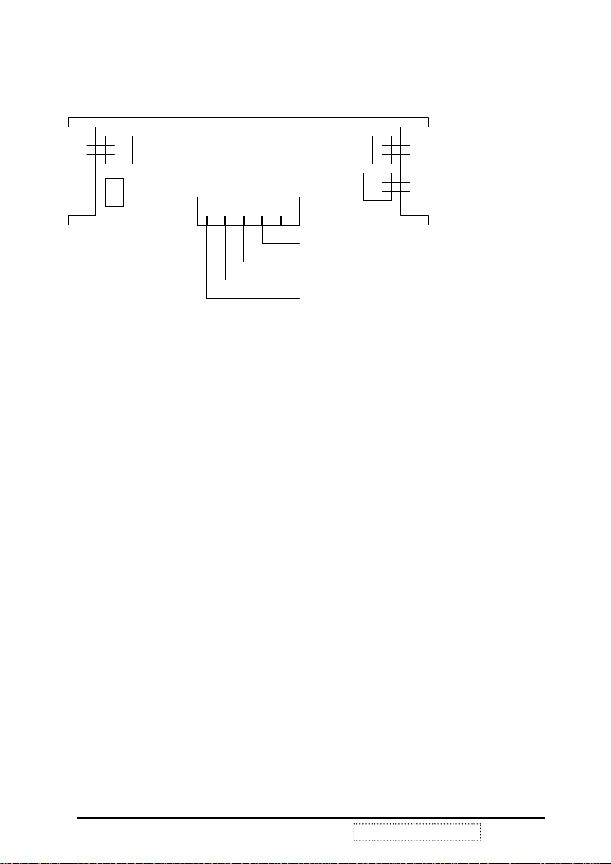
4-3 Inverter Board I/O Connections
HV out
HV out
RTN
RTN
CN4
CN5
CN3
1
CN1
CON
VEE
GND
VDD
CN2
RTN
RTN
HV out
HV out
NOTE: MANUFACTURER’S NAME MUST BE ON THE PRINTED SIDE FOR THE
INVERTER BOARD TO BE FACING UP.
4-4 Theory of Circuit Operation
VE510+ is a multi-frequency and multi-mode color TFT LCD monitor. It supports different
resolutions including XGA, SVGA, VGA and other various high resolution up to 1024x768 for
IBM, PC compatibles, Power PC and Macintosh. VE510+ uses a TFT LCD panel with a
0.297mm pixel pitch, provides 16.7 millions color images.
As the previous block diagram illustrates, VE510+ uses a highly integrated solution (U1:
Mascot V) that combines a high performance ADC with an advanced image process controller.
Using advanced image scaling algorithms, Mascot V has intelligently adaptive sub-algorithms
that will automatically optimize the display quality for different images – the text is sharper and
the graphics is smoother.
Furthermore, each TFT LCD monitor uses the 24LC02 (U14) chip to provide DDC1/2B¥ with
Analog Plug & Play, the DDC data format is EDID v1.3.
Digital process and control system allows users to control OSD menu values to change
monitor settings. The follow sections are major part discussions of the TFT LCD display
control board.
ViewSonic Corporation
13
Confidential --Do Not Copy VE510+-1

POWER SYSTEM
This product uses an external power adapter to provide DC+12V. It is the source of other
voltages +5VX, 3.3VX, and VLCD.
The voltage of +5VX is produced by regulator LM2596-5V (U5) and external components that
can realize DC to DC conversion from +12V to +5V. For some chips (MPU, ADC) that are
sensitive to any voltage variance, we need LDO 1084-3.3V (U11) to produce a stable voltage
3.3VX.
There is still an important consideration about power consumption. We must greatly reduce
the power consumption even up to 90% in power saving mode. So we need to switch off the
power that needn’t exist when the system enters to this mode. We use the P-channel
MOSFET TRLML6402 (Q1) to control the on/off state of the panel’s power VLCD.
See FIG1-1.
FIG1-1
ViewSonic Corporation
14
Confidential --Do Not Copy VE510+-1
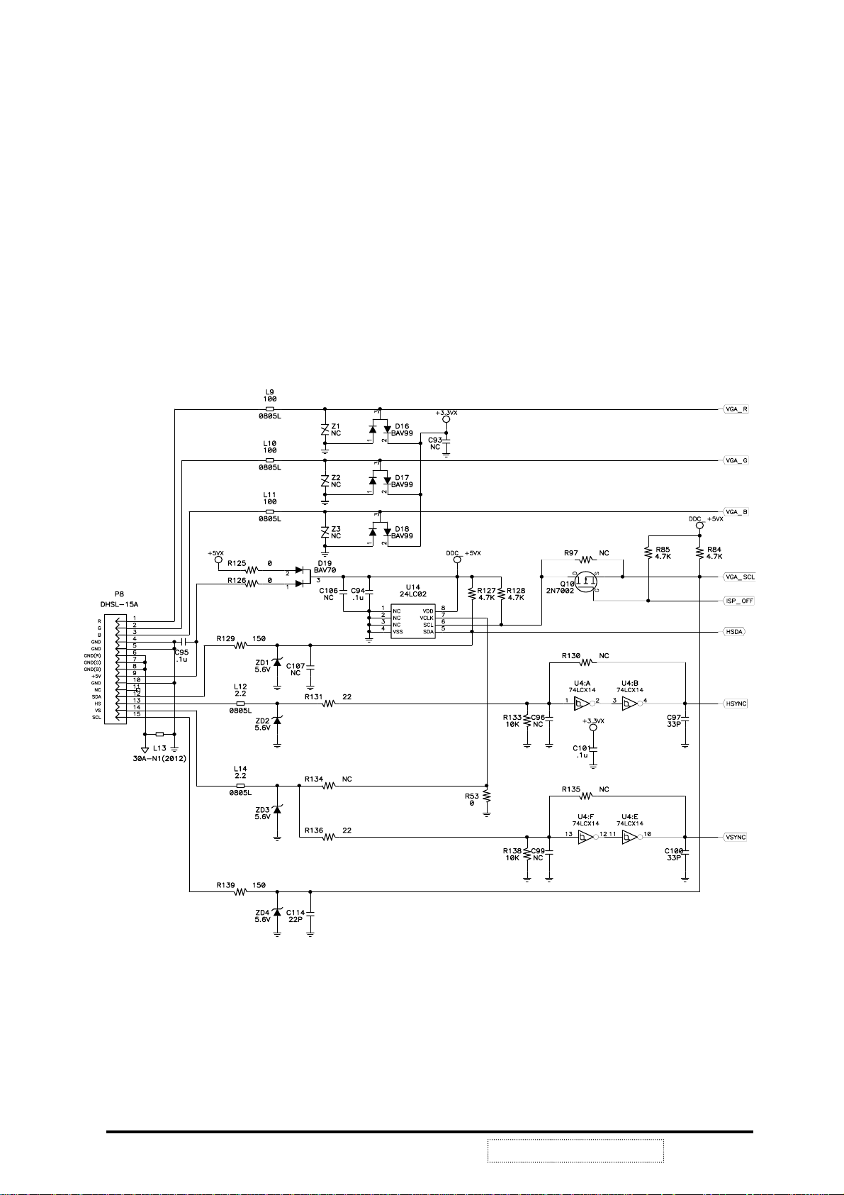
ANALOG SIGNAL INPUT and EDID
This product uses the internal function of Mascot V (U1) as a signal detector in order to
support separate SYNC, composite SYNC and SYNC on GREEN signals. The analog input
Horizontal and Vertical Sync signals pass through the Schmitt trigger buffer U4 to stabilize
then input to Mascot U1 pin38 VGA_VSYNC, pin39 VGA_HSYNC or pin40 SOGI and the
image processing. Then Mascot will detect the signal type if it is separate SYNC, composite
SYNC or SOG. MPU (U6) reads the input signal type from IIC protocol and does the correct
procedure to generate the proper signals to the whole system.
24LC02 (U14) chip provide DDC1/2B¥ with Analog Plug & Play, and the DDC data format is
EDID v1.3.
See FIG1-2.
ViewSonic Corporation
FIG1-2
15
Confidential --Do Not Copy VE510+-1

ANALOG to DIGITAL CONVERSION and PROCESSING
General Description of Mascot
Mascot V is a highly integrated solution (U1) that combines a high performance ADC with an
advanced image process controller. Using advanced image scaling algorithms, Mascot V has
intelligently adaptive sub-algorithms that will automatically optimize the display quality for
different images – the text is sharper and the graphics is smoother.
The built-in analog interface includes an 80MHz, 8-bit 3-channel ADC,
pre-amplifier, and VGA, allowing seamless support to resolution from VGA to
XGA. ADC function block diagram, see FIG3-1.
ViewSonic Corporation
FIG3-1 ADC Functional Block Diagram
16
Confidential --Do Not Copy VE510+-1

Clock Re-Generator Functional Block Diagram
FIG3-2 Clock Re-Generator
ADC Block Description
Variable Gain Amplifier (VGA)
The front-end circuit is designed to provide four major functions:
z Provide AC coupled interface with single-ended R/G/B input signal, convert single-ended
signal to differential signal, and define common mode voltage.
z Define CLAMPING voltage level with respect to ground for image brightness control.
z Perform user programmable precision gain amplification.
z Provide low impedance differential driver for ADC.
Phase Locked Loop (PLL) and Multi-Phase Generation
The phase locked loop (PLL) generates desired ADC sampling clock frequency (30 MHz
to 80 MHz) from external line clock CKREF. The exact frequency is register
programmable and related to the input line clock CKREF as follows:
Freq (PLL) = Freq (CKREF)* Ndiv <12:0>
To ease the graphic interface, a phase programmable output clock is also generated for
external use. The exact phase delay with respect to VCO output clock is register
programmable and can be formulated as follows:
T DELAY = IJ+Tclk * phase<4:0> / 32
Where is a systematic delay? Due to the periodic nature of the clock, user can practically
program the ADC sampling anywhere with respect to data in the step size of Tclk/32.
ADC
Based on the requirements for this ADC (high speed, low power and small size). The sub
ranging architecture is used to minimize the number of comparators. The interpolation
ViewSonic Corporation
17
Confidential --Do Not Copy VE510+-1

technique is also used to reduce the number of preamplifiers. Two identical 8bit ADC
converters are used to increase the throughput of sub ranging ADC to one conversion per
clock cycle.
Each ADC operates in two-step sub range, i.e. coarse (3 bits) and fine (5 bits). One to
four interpolations is performed in fine conversion step to minimize the number of
preamplifier and to improve differential non-linearity errors (DNL). In addition, in order to
prevent potential error occurred during coarse conversion, digital error correction
technique is also used.
Clock Re-Generator Functional Block Diagram
ViewSonic Corporation
FIG3-3 Clock Re-Generator
18
Confidential --Do Not Copy VE510+-1

Host Interface Control
Host interface controller is an interface between Mascot V and an external CPU. The access
to Mascot V internal internal registers, SRAM, programmable fonts, gamma tables, and ROM
is performed by interface controller. Mascot V provides single read/write and incremental
read/write. Mascot V supports I2C bus and SPI protocols. The bus protocol selection is
determined by pin CONFIG[4], and Mascot V slave address is determined by pin
CONFIG[3:0].
GPIO (General Purpose Input/Output)
Gerenal Purpose Input/Output
Mascot V has provided three pins for general purpose input/output(GPIO) pins; these pins can
be programmed as input or output pins; each GPIO pin has three registers for programming:
GPIO Input/output control register, GPIO output data register and GPIO input register; When
GPIO is programmed as output pin, GPIO Input/output control register is programmed as I
(output), and the output data is provided by GPIO output data register; When programmed as
input pin, GPIO Input/output control register is programmed as 0(input), the input value can be
accessed thrugh GPIO input register.
PWM (Pulse Width Modulation)
Mascot V has provided two sets of PWM, each PWM can generate programmable periodic
square waves; The generated wave consists of low period and high period, and the low period,
and the low period and high period can be programmed separately, each period basic cycles
that can be programmed to be 0Д255 basic cycles; and the basic cycle is defined by design,
which also has four kinds of basic cycles can be chosen by programming.
Sync Processor
Sync Processor is used to detect input source (analog RGB or 24-bit RGB) and generate
interrupt to an external external CPU if input source changes. Then the CPU can program
Mascot V correctly according to different input sources. Sync Processor can generate
interrupt when there are frequency changes, Hsync and Vsync polarity changes, and when
there is no input signal. Sync processor provides h_counter and v_counter which are stored in
registers CR0B, CR0C, CR0D, and CR0E. V frequnecy can be calculated by (refclk/64) /
v_counter or 187.5kHz/ v_counter for using 12MHz refclk. H frequency is calculated by
(refclk/512k) * h_counter or 46.5Hz * h_counter or 46.5Hz * h_counter for using 12MHz refclk.
Mascot V Sync Processor can also support composite Sync and sync-on-green inputs. If sync
Processor detect that the input source is compusite sync or sync-on-green input, Mascot V
will separate composite sync or sync-on-green to Hsync and Vsync.
Calibration
Calibration block performs position calibration, color calibration and phase calibration. In
position calibration, non-zero data are detected horizontally and vertically. The Left most and
right most positions and their corresponding pitch can be found.Also Horizontal Total &
Vertical Total are calculated.
Color calibration includes maximum color component detection, color read back from
specified position and maximum color difference in 2 neighboring pixels.
ViewSonic Corporation
19
Confidential --Do Not Copy VE510+-1

In maximum color calibration, the pixel which has the maximum color component (based on
CRB1[3:0]) can be found. In color read back calibration, the color component (based on
CRB[3:0]) for specific position can be read back. In maximum color difference calibration, for
specific color component, color differences between every 2 neighboring pixels are compared
from first till the last pair within a frame. The position which has the largest color difference
with its neighboring data is found.
Phase calibration can report pixel mismatch in up to 32 frames based on 2 specified points.
Capture Controller
Capture Controller is used to generate synchronization signals which are used for
internal Mascot V. Within Capture Controller block(FIG3-4), incoming data are
processed, filtered and minimized and aligned with controlling signals. Important
internal synchronization signals include H_cnt, V_cnt, internal blank, and end_of_frame.
FIG3-4 Capture Controller block
YUV to RGB Block
This block performs color space format conversion. Mascot V can convert 16 Bit YUV, RGB
into 24 Bit RGB data format.
Scaling Down
This block is used to conditionally drop incoming data if the incoming resolution greater than
1024x768 which is the physical resolution of the panel. A modified version of the Bresenham
line-drawing algorithm is used to determine which incoming data not to discard.
ViewSonic Corporation
20
Confidential --Do Not Copy VE510+-1

Zoom Buffer
Zoom Buffer is the storage and is used to store input data for scaling (zoom) function.
Zoom Buffer Write Control and Zoom Buffer Read Control
This block generates write and read control signal to access zoom buffer.
Vertical Zoom Filter and Horizontal Zoom Filter
The Mascot V scaling engine uses an advanced scaling technology and provides high quality
scaling of text images, graphic images and real-time video.
Display Control
ViewSonic Corporation
FIG3-5 Display Control
21
Confidential --Do Not Copy VE510+-1

On-Screen Display
Mascot V OSD display support 256 different fonts at size of 12x18, 256 fonts contain
128 fixed fonts that stored in internal ROM, other 128 programmable fonts stored in
internal SRAM. OSD also supports Overlay port interface and color look-up table with
4 color indices from external OSD and Opaque, Translucence, Transparent display.
Diagram listed below is the concept of how OSD retrieves and displays OSD Font.
See FIG3-6.
FIG3-6 On-Screen Display
When OSD key is been pressed, firmware will detect the change and perform the
procedure, once firmware start “drawing” OSD, it will program the OSD code and
attribute to the OSD SRAM. Chip will look-up the OSD code then retrieve the character
font data that corresponding to the code and then display the character on LCD panel.
There are 320 memory spaces from 0 to 319 in SRAM. It is sequentially mapped to the
OSD frame started from the upper-right corner and goes horizontally to the upper-left
corner and then move to 2
nd
row etc. Ended at left-bottom corner. OSD frame are divided
by 0Д9 in row, total is 32x10=320 characters.
Diagram listed below is the concept of how 24bit RGB OSD character been composed,
see FIG3-7 OSD Display Flow Chart. Each OSD character font data that read out from
ROM table will use the 4-bit foreground and 4-bit background color to determine its color.
Use this 4-bit color index to look-up the palette and select related 15bit RGB foreground
and background color. And added 3bit 0 to each R, G, and B channel then generate 24it
RGB color for the OSD character.
ViewSonic Corporation
22
Confidential --Do Not Copy VE510+-1

FIG3-7 OSD Display Flow Chart
Overlay Block
The Overlay Block mixes the scaled image data and OSD data…
Overlay block mix mode is following 4 ways listed below:
Transparent (Display)
Opaque (OSD)
Background Transparent (0 bits = Display)
Translucent ((Display + OSD)/2)
RGB Offset and Gamma controller Block:
The RGB offset function is used to adjust brightness of RGB data. It provides a simple shift
(positive or negative) for each of the 3 color channels.
The Gamma Correction Block controls the linearity of RGB data.
It is used to adjust the RGB data according to the individual display characteristics and human
eyes favorite. In addition, the gamma table may be used for contrast, brightness, and white
balance (temperature) adjustment. The Gamma Correction linearity can be programmed
through host interface.
Dithering Block
The Dithering Block generates output RGB data for TFT panels that have fewer than 8 bits for
R, G and B input. Mascot V uses a proprietary algorythm to generate smooth shade colors.
Panel Interface
Mascot V chip interfaces with all commonly used active matrix flat panel, e.g. 640x480,
800x600, and 1024x768 .
ViewSonic Corporation
23
Confidential --Do Not Copy VE510+-1
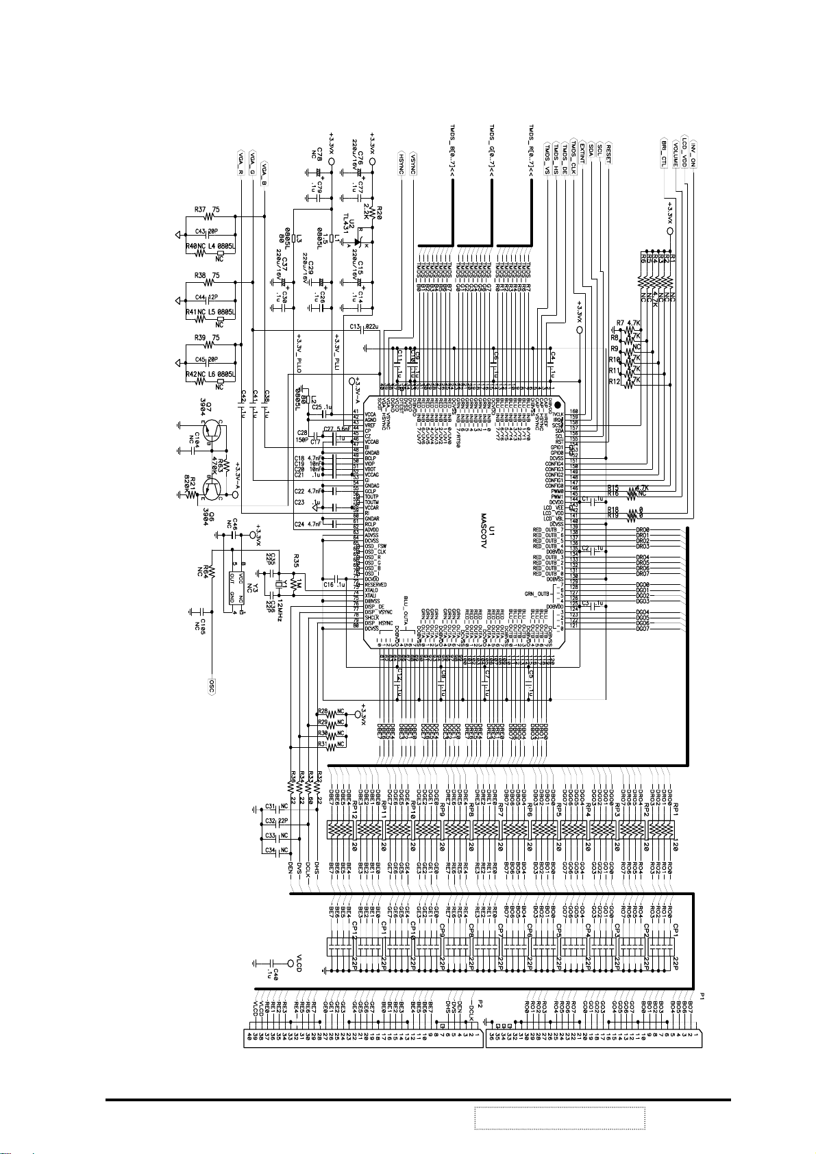
FIG3-8 Mascot function block
ViewSonic Corporation
24
Confidential --Do Not Copy VE510+-1
MPU
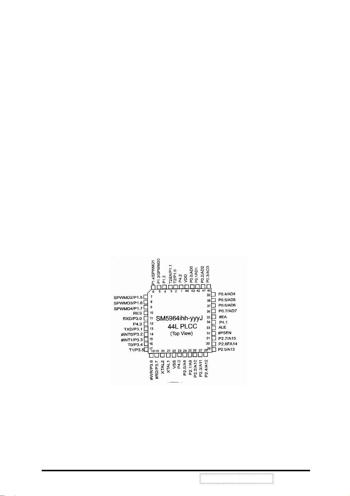
VE510+ is controlled by a µ-controlled SM5964.
Description of SM5964
The SM5964 series product is an 8 – bit single chip microcontroller with 64KB flash &
1K byte RAM embedded. It has In-System Programming (ISP) function and is a
derivative of the 8052 microcontroller family. It has 5-channel SPWM built-in. User can
access on-chip expanded RAM with easier and faster way by its ‘bank mapping direct
addressing mode’ scheme. With its hardware features and powerful instruction set, it’s
straight forward to make it a versatile and cost effective controller for those applications
which demand up to 32 I/O pins for PDIP package or up to 36 I/O pins for PLCC/QFP
package, or applications which need up to 64K byte flash memory either for program or
for data or mixed.
To program the on-chip flash memory, a commercial writer is available to do it in parallel
programming method. The on-chip flash memory can be programmed in either parallel
or serial interface with its ISP feature.
Ordering Information
SM5964ihhk (blank chip)
SM5964ihh – yyyk
I: process identifier {C, L}
hh: working clock in MHz {40}.
yyy: production code {001,…,999}
k: package type postfix {as below table}
ViewSonic Corporation
FIG4-1 SM5964 Pin Configuration
25
Confidential --Do Not Copy VE510+-1

Features of SM5964
Working voltage: 4.5V through 5.5V
Program voltage: 5V
General 8052 family compatible
12 clocks per machine cycle
64K byte on chip flash memory with In-System Programming (ISP) capability
1024 byte on chip data RAM
Three 16 bit Timers/Counters
One Watch Dog Timer
Four 8-bit I/O ports for PDIP package
Four 8-bit I/O ports + one 4-bit I/O ports for PLCC or QFP package
Full duplex serial channel
Bit operation instruction
Page free jumps
8-bit Unsigned Division
8-bit Unsigned Multiply
BCD arithmetic
Direct Addressing
Indirect Addressing
Nested Interrupt
Two priority level interrupt
A serial I/O port
Power save modes: Idle mode and Power down mode
Code protection function
Low EMI (inhibit ALE)
Reset with address $0000 blank initiate ISP service program
ISP service program space configurable in N*512byte (N=0 to 8) size
Bank mapping direct addressing mode for access on-chip RAM
Five channel Specific PWM (SPWM) build-in
Direct LED drive output at port 4
ViewSonic Corporation
26
Confidential --Do Not Copy VE510+-1

FIG4-2 MPU Control Block
ViewSonic Corporation
27
Confidential --Do Not Copy VE510+-1

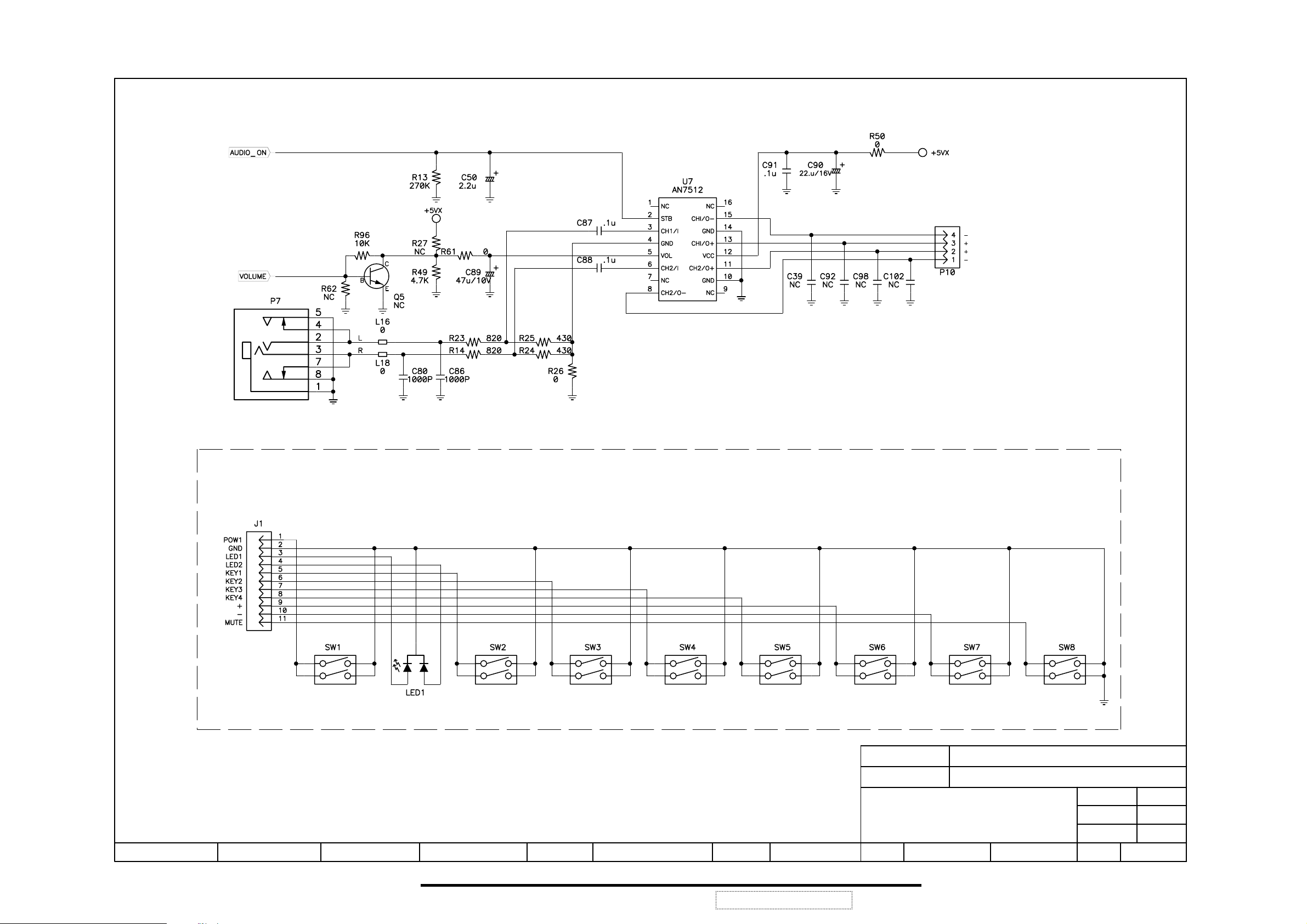
AUDIO
VE510+ use AN7512 for stereo system, AN7512 is a dual 1-W BTL (Balanced
Transformer-Less) audio power amplifier IC. Speakers and microphone stay
on the rest of the monitor is in power saving. See FIG5-1.
FIG5-1 Audio block diagram
ViewSonic Corporation
28
Confidential --Do Not Copy VE510+-1

5. Adjustment
On Screen Display
OSD (On Screen Display) function is supported on each the TFT LCD analog
display monitors and is controlled by easy to use Button 1, Down, Up, Button 2,
Power (Soft Switch), Mute, Volume – and Volume +.
(Power, 1, 2 and mute button should be one shot logic operation).
MAIN MENU Sub-Function Value
AUTO IMAGE ADJUST
CONTRAST/ BRIGHTNESS Adjustment Bar
COLOR ADJUST 6500K (default)
9300K (default)
USER
RED Adjustment Bar
GREEN Adjustment Bar
BLUE Adjustment Bar
INFORMATION
LANGUAGE ENGLISH
FRANCAIS
DEUTSCH
ITALIANO
ESPANOL
SUOMI
JAPANESE
CHINESE TRADITIONAL
CHINESE SIMPLIFIED
MANUAL IMAGE ADJUST H SIZE
H/V POSITION
FINE TUNE
SHARPNESS ON/OFF
SETUP MENU RESOLUTION NOTICE ENABLE/DISABLE
BACKGROUND ON/OFF
MEMORY RECALL
ViewSonic Corporation
OSD POSITION H/V Adjustment Bar
OSD TIME OUT 5S/15S/30S/60S
29
Confidential --Do Not Copy VE510+-1

OSD Lock short cuts function for the buttons
1. The OSD lock will be activated by pressing the front panel control buttons
"(1), & (up)" for 10 seconds. If the user then tries to access the OSD by
pressing any of the buttons "1", "down", "up", "2" a message will appear on
the screen for 3 seconds showing "OSD Locked". The OSD lock will be
deactivated by pressing the front panel control buttons "(1), & (up)" again
for 10 seconds.
Note 1: LED flashes orange when the OSD has been Locked or Unlocked.
2. The power button lock will be activated by pressing the front panel control
buttons "(1), & (down)" for 10 seconds. Locking the power button means
that the user won't be able to turn off the LCD while the power button is
locked. If the user presses the power button while it is locked, a message
will appear on the screen for 3 seconds showing "Power Button Locked". It
also means that with the power button locked, the LCD would automatically
turn back "On" when power is restored after a power failure. If the power
button is not in the locked mode, then power should return to its previous
state when power is restored after a power failure. The power button lock
will be deactivated by pressing the front panel control buttons "(1), &
(down)" again for 10 seconds.
Note: LED flashes orange when the power button has been Locked or
Unlocked.
Short Cut Keys:
Auto Image Adjust: press button [2]
Contrast / Brightness: press buttons Up or Down
[DOWN] + [UP] arrows = recall Contrast and Brightness while in the Contrast
or Brightness adjustment, or when the OSD is not open.
[Audio-] + [Audio+] = recall volume to 50% whether or not the OSD is open.
OSD lock and unlock: press two buttons [1] & [Up] simultaneously for 10
seconds.
Power lock and unlock: press two buttons [1] & [Down] simultaneously for 10
seconds.
Memory Recall is to recall the following functions to factory setting:
ViewSonic Corporation
30
Confidential --Do Not Copy VE510+-1

Contrast, brightness, h size, h/v position, color temperature @ 6500K, OSD
position, sharpness, OSD timeout, volume, and Resolution Notice.
Note: Memory Recall should have no effect for Mute, Language, or User Color
Settings.
ViewSonic Corporation
31
Confidential --Do Not Copy VE510+-1

6.Troubleshooting Flow Chart
6-1 Figures of Waveform
Input Signal: VGA Card Sis 620
Resolution 1024X768
HSYNC 48.5 KHz
VSYNC 60Hz
CH1: INPUT HSYNC (PIN13 OF P8)
CH2: INPUT VSYNC (PIN14 OF P8)
CH1: VGA_HSYNC (PIN39 OF U1)
CH2: VGA_VSYNC (PIN40 OF U1)
ViewSonic Corporation
32
Confidential --Do Not Copy VE510+-1

CH1: DISP_HSYNC (PIN79 OF U1)
CH2: DISP_VSYNC (PIN77 OF U1)
CH1: DISP_DE (PIN76 OF U1)
CH2: DISP_VSYNC (PIN77 OF U1)
ViewSonic Corporation
33
Confidential --Do Not Copy VE510+-1

CH1: DISP_DE (PIN76 OF U1)
CH2: DISP_HSYNC (PIN79 OF U1)
CH1: BLU_OUTB_4 (PIN116 OF U1)
CH2: HSCLK (PIN78 OF U1)
ViewSonic Corporation
34
Confidential --Do Not Copy VE510+-1

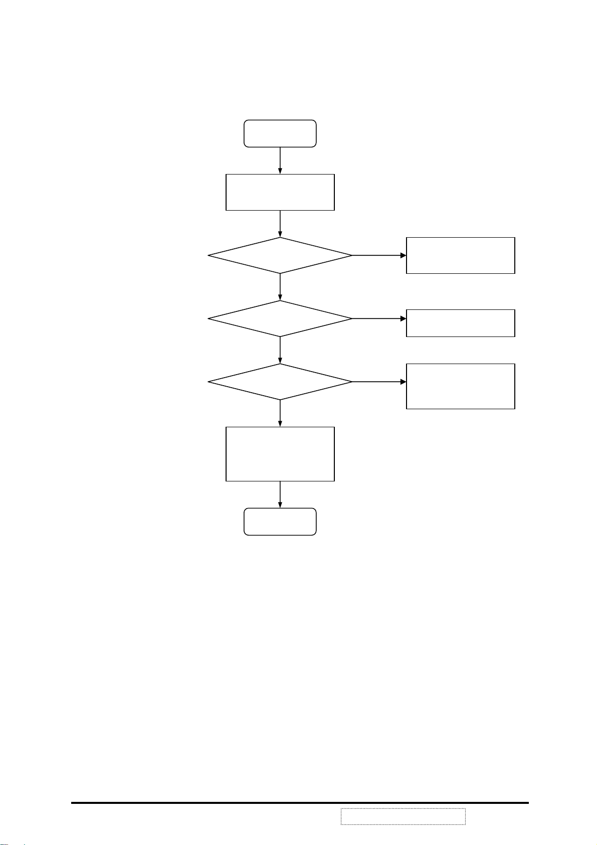
6-2 Troubleshooting Flow Chart
ONITOR DOES NOT WORK
M
Start
Is LED lighting?
Yes
Is LED green?
Yes
Is backlight on?
Yes
Does U1 input?
Yes
Does U1 output?
No
No
No
No
No
1. Is adaptor’s output+12V?
2. Is DC Jack (P6) connector ok?
3. Is +5Vx ok?
4. Check LED signal?
LED lights orange, monitor is in
power saving mode
1. Check video cable
2. Is the timing supported?
1. Is inverter ok?
2. Is P3 connected ok?
Check U1 input well; include
VGA_VSYNC, VGA_HSYNC, or
SOGI, and RI, GI, BI.
It means data to panel
1. Are P1and P2 connected well.
2. Check VLCD?
3. Check DHS, DVS, DCLK, DEN
4. Is panel ok?
Yes
Does volume out?
Yes
END
No
It means no audio
1. Check phone jack P7, make sure
audio signal input?
2. Check VCC & STB (Stand-by) of
U7
3. Is U7 output ok?
4. Are speakers ok?
ViewSonic Corporation
35
Confidential --Do Not Copy VE510+-1
R, G, B COLOR IS NOT DISPLAY CORRECT
Start
Check OSD color setting &
execute AUTO-CONTRAST
Input signal ok?
Yes
U1 input correct.
Yes
U1 output correct.
Yes
1. Is P1 & P2 connected well?
2. Is panel working well?
END
No
No
No
1. Check video cable
2. Check settings of host system
Check RI, GI, BI level.
1. Check resistor arrays of U1
outputs
2. Check power of voltage
3. Check U1 to P1 &P2
ViewSonic Corporation
36
Confidential --Do Not Copy VE510+-1

TROUBLE OF DC-DC CONVERTER
Start
Is U5 pin1 correct?
Yes
+5Vx correct?
Yes
VLCD correct?
Yes
3.3Vx correct?
Yes
END
No
No
No
No
The voltage is about + 12V
1. Check power adaptor
2. Check power cable
3. Check FUSE1
The voltage is about + 5.0V
1. Check U5 output
2. Check L17 frequency
The voltage is about +5.0V
Check C57 & pin 8 of U6
Check U11 output
ViewSonic Corporation
37
Confidential --Do Not Copy VE510+-1

TROUBLE OF DDC READING
Start
Analog DDC OK?
Yes
END
No
Support DDC1/2B
1. Analog cable ok?
2. Check signal U14 (SDA, SCL)
3. Check IIC protocol
ViewSonic Corporation
38
Confidential --Do Not Copy VE510+-1

7. Schematics Diagrams
˔ˣˣ˥ˢ˩˘˗ʳ˕ˬˍ ˣ˖˕ʳˣ˂ˡ
˖˛˘˖˞˘˗ʳ˕ˬˍ ˘˖ˡʳˡˢ
ViewSonic Corporation
˃˄ˊ˄ˀ˅˅ˇ˅ˀ˃ˊ˅˃ ˔ˣ˖ˡ˃˅˃ˊ˃˃˄˅
39
Confidential --Do Not Copy VE510+-1
ˠˢ˗˘˟
˩˘ˈ˄˃ʾˠ˥˧ʳʻˆ˄ˈ˃ˀ˃ˌˆ˅ˀ˃˄ˈ˃ʼ
˖˜˥˖˨˜˧˥ˬ ˠ˴˼ʳ˵˴˷
ViewSonic Corporation
˙˜˟˘ˍ
˩˘ˈ˄˃ʾˠ˃ˁ˶˻ ˩˘ˈ˄˃ʾˀˠ˃ˁˣ˖˕
˦˛˘˘˧
˥˘˩ˍ
ˣ˖˕ʳ˥˘˩ˍ
˗˔˧˘
ˢ˙ ˇ˄
˃˃
˃˃

ˠˢ˗˘˟
˩˘ˈ˄˃ʾˠ˥˧ʳʻˆ˄ˈ˃ˀ˃ˌˆ˅ˀ˃˄ˈ˃ʼ
˔ˣˣ˥ˢ˩˘˗ʳ˕ˬˍ ˣ˖˕ʳˣ˂ˡ
˖˛˘˖˞˘˗ʳ˕ˬˍ ˘˖ˡʳˡˢ ˗˔˧˘
ViewSonic Corporation
˃˄ˊ˄ˀ˅˅ˇ˅ˀ˃ˊ˅˃
40
˖˜˥˖˨˜˧˥ˬ
˔ˣ˖ˡ˃˅˃ˊ˃˃˄˅
Confidential --Do Not Copy VE510+-1
˙˜˟˘ˍ
ˠ˴˼ʳ˵˴˷
ViewSonic Corporation
˩˘ˈ˄˃ʾˠ˃ˁ˶˻
˩˘ˈ˄˃ʾˀˠ˃ˁˣ˖˕
˦˛˘˘˧
˥˘˩ˍ
ˣ˖˕ʳ˥˘˩ˍ
ˢ˙ ˇ˅
˃˃
˃˃

ˠˢ˗˘˟ ˩˘ˈ˄˃ʾˠ˥˧ʳʻˆ˄ˈ˃ˀ˃ˌˆ˅ˀ˃˄ˈ˃ʼ
˔ˣˣ˥ˢ˩˘˗ʳ˕ˬˍ ˖˛˘˖˞˘˗ʳ˕ˬˍ ˣ˖˕ʳˣ˂ˡ
ViewSonic Corporation
˖˜˥˖˨˜˧˥ˬ
ViewSonic Corporation
˃˄ˊ˄ˀ˅˅ˇ˅ˀ˃ˊ˅˃ ˔ˣ˖ˡ˃˅˃ˊ˃˃˄˅ ˩˘ˈ˄˃ʾˀˠ˃ˁˣ˖˕˩˘ˈ˄˃ʾˠ˃ˁ˶˻
41
˘˖ˡʳˡˢ ˙˜˟˘ˍ ˗˔˧˘
Confidential --Do Not Copy VE510+-1
ˠ˴˼ʳ˵˴˷
˦˛˘˘˧
˥˘˩ˍ
ˣ˖˕ʳ˥˘˩ˍ
ˢ˙
ˆˇ
˃˃
˃˃
˗˜˦ˣ˟˔ˬʳ˕ˢ˔˥˗
˙˜˟˘ˍ˩˘ˈ˄˃ʾˀ˗˃ˁˣ˖˕
ˣ˂ˡˍ˃˄ˊ˃ˀ˄ˊˇ˃ˀ˃ˉˉ˃
˔˦˦ˬʺˍˆ˄ˈ˃ˀ˃˄ˋ˅ˀ˃˄ˈˉ
˔ˣˣ˥ˢ˩˘˗ʳ˕ˬˍ ˣ˖˕ʳˣ˂ˡ
˖˛˘˖˞˘˗ʳ˕ˬˍ ˘˖ˡʳˡˢ ˙˜˟˘ˍ
ViewSonic Corporation
ˠˢ˗˘˟
˩˘ˈ˄˃ʾˠ˥˧ʳʻˆ˄ˈ˃ˀ˃ˌˆ˅ˀ˃˄ˈ˃ʼ
˖˜˥˖˨˜˧˥ˬ ˠ˔˜ˡʳ˕ˢ˔˥˗
ViewSonic Corporation
˃˄ˊ˄ˀ˅˅ˇ˅ˀ˃ˊ˅˃ ˔ˣ˖ˡ˃˅˃ˊ˃˃˄˅ ˩˘ˈ˄˃ʾˀˠ˃ˁˣ˖˕˩˘ˈ˄˃ʾˠ˃ˁ˶˻
42
Confidential --Do Not Copy VE510+-1
˦˛˘˘˧
˥˘˩ˍ
ˣ˖˕ʳ˥˘˩ˍ ˃˃
ˇ
ˢ˙
˃˃
˗˔˧˘
ˇ
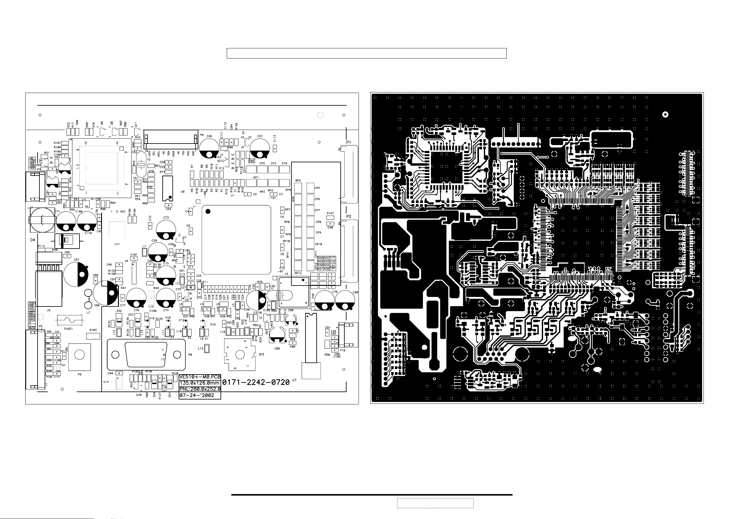
8. PCB Layout
ViewSonic Corporation
43
Confidential --Do Not Copy VE510+-1

ViewSonic Corporation
44
Confidential --Do Not Copy VE510+-1

9.Explode Diagram and Mechanical Parts List
ViewSonic Corporation
45
Confidential --Do Not Copy VE510+-1

Mechanical Parts List
ITEM VIEWSONIC P/N DESCRIPTION Ref No Qty
1 C-FP-0301-0874 FRONT PANEL CAB-(VE510+) DELL-SILVER ASS'Y 1801-0110-5021 1
2 C-FP-0301-0875 FRONT PANEL CAB-(VG150M) G7397 ASS'Y 1801-0110-5010 1
3 PL-BT-0706-0123 BUTTON (DELL-SILVER) (VE510+) 1701-0409-6010 1
3 PL-BT-0706-0122 BUTTON (G7397) (VG150M) 1701-0409-6000 1
3 PL-BT-0706-0124 BUTTON (MID.GRAY-89121) (VG150MB) 1701-0409-6020 1
4 B-CB-0206-0140 LCD DISPLAY BD ASS'Y (VE510+) 3150-0182-0156 1
5 B-SB-0221-0474 INSULATOR-INVERTER 1947-1200-0440 1
6 M-LCD-0826-0105 LCD MODULE 15.0" TFT AA150XC01(ADI) 0211-0150-2855 1
7 M-MS-0808-7663 WH FCC 36P 164MM CORE*2 0450-2836-0030 1
8 M-MS-0808-7665 WH FCC 40P 102MM CORE*1 0460-2840-0030 1
9 M-MS-0808-8069 GASKET BLOCK (5*3.5*50MM) 1947-1800-0070 2
10 M-MS-0808-6036 GASKET BLOCK (10.0*10.5*60MM) 1947-1700-0260 2
11 M-MS-0808-8068 INSULATOR-D (L1-150T) 1947-1200-0171 1
12 M-MS-0808-6035 SHIELDING AL. TAPE (70.0*50.0) 1947-1700-0130 2
13 M-MS-0808-7666 FRAME BRACKET 1712-0100-305X 1
14 B-MB-0201-0676 LCD 15.0" MAIN BD ASS'Y (VE510+) 3150-0932-0150 1
14 B-MB-0201-0677 LCD 15.0" MAIN BD ASS'Y (VG150M) 3150-1102-0150 1
14 B-MB-0201-0724 LCD 15.0" MAIN BD ASS'Y (VG150MB) 3150-1112-0150 1
15 E-SK-0412-0051 SPEAKER 8OHM 2W 40*20MM (TH4020M8-05) 0335-1080-0240 2
16 M-MS-0808-7669 SPONG (70*11*15) 1947-1500-0440 1
17 M-MS-0808-7667 SHIELD-M/B (VG150M/MB) 1712-0500-0870 1
18 B-SB-0221-0445 INVERTER DC-AC (T651007.00) REV:4.0 0500-0105-0360 1
19 M-MS-0808-8067 INSULATOR-B (L1-150T) 1947-1200-0140 1
20 M-MS-0808-8062 SHIELD-INV. (V1-150T) 1712-0500-0610 1
21 C-BC-0302-0385 REAR COVER CAB. (VSC-BLACK-792) (VE510+) 1701-0203-9000 1
21 C-BC-0302-0421 REAR COVER CAB. (G7397) (VG150M) 1701-0203-9010 1
21 C-BC-0302-0422 REAR COVER CAB.(MID.GRAY-89121) ( VG150MB) 1701-0203-9020 1
22 M-MS-0808-8065 REAR LOGO PLATE VIEWSONIC (PLASTIC) 1936-1000-0240 1
22 M-MS-0808-7668 REAR LOGO PLATE VIEWSONIC (G7397) VG150M 1936-1000-0270 1
22 M-MS-0808-8349 REAR LOGO PLATE (VG150MB WITHOUT SILVER COATIN) 1936-1000-0290 1
23 M-CV-0830-2365 HINGE COVER (VSC-BLACK-792) (VE510+) 1701-1901-1001 1
23 M-CV-0830-2366 HING COVER (G7397) (VG150M) 1701-1901-1011 1
23 M-CV-0830-2367 HINGE COVER (MID.GRAY-89121) (VG150MB) 1701-1901-1021 1
24 M-MS-0808-7910 HINGE ASSEMBLY (L1-150) 1712-0900-0220 1
25 PL-PS-0715-0155 BASE CAB. (ABS 94HB VSC-BLACK-792) VE510+ 1701-0507-3000 1
25 PL-PS-0715-0152 BASE CAB. (ABS 94HB G7397) VG150M 1701-0507-3010 1
25 PL-PS-0715-0174 BASE CAB. (ABS 94HB MID.GRAY-98121) VG150MB 1701-0507-3020 1
26 M-MS-0808-7909 BASE BRACKET (SECC) 1712-0100-2500 1
27 PL-PD-0714-0005 BASE FOOT (18.0*1.5) 1701-1000-0010 4
28 M-LB-0813-0742 B/C LBL VIEWSONIC VE510+ 1936-1100-4030 1
28 M-LB-0813-0741 B/C LBL VIEWSONIC VG150M 1936-1100-4020 1
28 M-LB-0813-0743 B/C LBL VIEWSONIC VG150MB 1936-1100-4280 1
29 M-MS-0808-4677 V.SONIC LOGO (AL. PLATE) 1936-1000-0100 1
30 M-MS-0808-7906 WH PH5P-PH5- 1061#26 40MM 0460-1005-0120 1
31 M-MS-0808-7664 WH PH11P-PH11P 1061#26 90MM CORE*1 0460-1011-0020 1
32 M-MS-0808-4725 SHIELDING AL. TAPE (70.0*40.0) 1947-1700-0090 1
35 M-SCW-0824-0363 MAC. SCREW-MPSWF M4.0*12.0l, NI 1720-1504-1220 2
36 M-SCW-0824-0626 MAC. SCREW-MPSWF M4.0*8.0l, ZN-CC 1720-1504-0810 4
37 M-SCW-0824-0625 TAP. SCREW-TF #3.0*6.0L, ZN-CC 1721-3003-0610 2
38 M-SCW-0824-0648 MAC. SCREW-MR M2.0*3.0L, NI 1720-1002-0320 4
39 M-SCW-0824-0553 MAC. SCREW-MB M3.0*4.0L, BLK-NI 1720-0003-0450 16
39 M-SCW-0824-0362 MAC. SCREW-MB M3.0*4.0L, ZN-CC 1720-0003-0410 16
40 M-SCW-0824-0556 TAP. SCREW-TB #3.0*10.0L, BLK-NI 1721-0003-1050 9
40 M-SCW-0824-0366 TAP. SCREW-TB #3.0*10.0L, NI 1721-0003-1020 9
41 M-SCW-0824-0649 MAC. SCREW-MI M3.0*5.0L, ZN 1720-5003-0500 4
42 M-SCW-0824-0723 TAP. SCREW-TP M2.0*6.0L, NI 1712-1020-0620 10
43 M-SCW-0824-0724 MAC. SCREW-MHSW #4-40*5.0L, NI 1720-7344-0520 2
ViewSonic Corporation
46
Confidential --Do Not Copy VE510+-1

10. Recommended Spare Parts List
ITEM VIEWSONIC P/N DESCRIPTION REF.No LOCATION
POWER CORD 6FT 220V VDE 0320-3000-0010
POWER CORD 6FT 110V UL/CSA AL 0320-4000-0010
S.CABLE 1800mm 15(3R-3R) 3+6C/PC99 +PIN9 BLK 0321-0000-0040
A.CABLE 3.5@* 2547#28 1800mm PC99 (BLK) 0322-2000-0010
SPEAKER 8ohm 2W 40*20mm (TH4020M8-05) *2 0335-1080-0240
WH PH4P 1061#26 110/310mm 0460-1004-0101
WH PH5P-PH5P 1061#26 40mm 0460-1005-0120
WH PH11P-PH11P 1061#26 90mm core*1 0460-1011-0020
WH FPCB L1-150 FOR ADI 0460-2900-0311
INVERTER DC-AC (T65I007.00) REV:4 0500-0105-0360
FRONT PANEL CAB. (ABS,94HB DELL-SILVER) 1701-0110-5021
REAR COVER CAB. (ABS,94HB VSC-BLACK-792) 1701-0203-9000
EPS FORM-A (VA520) 1925-1000-1040
EPS FORM-B (VA520) 1925-1000-1050
CARTON VIEWSONIC VE510+ 1925-1200-3580
CD WIZARD + QSG VIEWSONIC VE510+ 1925-1300-3600
TCO99 ECO DOCUMENT 1925-1400-0090
15" LCD DISPLAY BD ASS'Y VE510+ (MRT) 3150-0182-0156
LCD MAIN BD ASS'Y VE510+ (ADI) (MRT) 3150-0932-0150
DUAL SURFACE DIODES BAV70 SMD (SOT-23) 0390-5001-8293 D19
SCHOTTKY DIODE SB340 T 0390-6000-9172 D4
PICO FUSE 125V 3.5A 3*7MM (R25103.5) 0182-1352-3703 FUSE1
DRUM CORE L:70UH 2A(10*16) 0361-1000-0120 L17
MOSFET IRLML6402 P-CH SOT-23 0420-2000-6601 Q1
MOSFET N-CH 2N7002E-T1 SMD (SOT-23) 0420-1002-4621 Q10
TRANSISTOR MMBT3904LT1 SMD T 0410-5000-1610 Q11
TRANSISTOR MMBT3904LT1 SMD T 0410-5000-1610 Q2
TRANSISTOR MMBT3904LT1 SMD T 0410-5000-1610 Q4
TRANSISTOR MMBT3904LT1 SMD T 0410-5000-1610 Q6
TRANSISTOR MMBT3904LT1 SMD T 0410-5000-1610 Q7
MOSFET N-CH 2N7002E-T1 SMD (SOT-23) 0420-1002-4621 Q8
MOSFET N-CH 2N7002E-T1 SMD (SOT-23) 0420-1002-4621 Q9
IC MASCOT V PQFP 160PIN 0430-5007-1976 U1
IC AIC1084-33CE SMD 3PIN TO-252 0430-6003-0069 U11
IC AT24C02N-10SC-2.7 SMD 8PIN 0430-3001-1011 U14
IC AMC431 SMD(SOT-23) 3PIN 0430-6000-4051 U2
IC AME8500AEET CF46 0430-7010-0075 U3
IC 74LCX14 SMD 14PIN(SOIC) 0430-1004-4035 U4
IC LM2596S-5.0 TO-263 5PIN 0430-6001-7204 U5
IC SM5964C40J 44PIN PLCC 0430-5007-5578 U6
IC AN7512 DIP 16PIN 0430-4007-2168 U7
IC 24LC08B/P DIP 8PIN 0430-3000-4117 U8
X'TAL 12MHZ 49/US CL:30PF 0280-1200-0015 Y1
X'TAL 12MHZ 49/US CL:30PF 0280-1200-0015 Y2
10
11
12
13
14
15
16
17
18
19
20
21
22
23
24
25
26
27
28
29
30
31
32
33
34
35
36
37
38
39
40
41
42
43
44
A-PC-0106-0084
A-PC-0106-0039
A-VC-0101-0226
A-RCA-0113-0016
E-SK-0412-0051
M-MS-0808-8184
M-MS-0808-7906
M-MS-0808-7664
M-MS-0808-7908
B-SB-0221-0445
C-FP-0301-0874
C-BC-0302-0385
P-FM-0602-0720
P-FM-0602-0721
P-BX-0601-0690
A-CD-VE510+
M-MS-0808-4721
B-SB-0221-0473
B-MB-0201-2723
E-D-0403-1740
E-D-0403-1743
E-FS-0410-0084
E-L-0407-1057
E-Q-0402-1578
E-Q-0402-1577
E-Q-0402-1087
E-Q-0402-1087
E-Q-0402-1087
E-Q-0402-1087
E-Q-0402-1087
E-Q-0402-1577
E-Q-0402-1577
E-IC-0401-2642
E-IC-0401-2644
E-IC-0401-1982
E-IC-0401-2346
E-IC-0401-2645
E-IC-0401-2521
E-IC-0401-2373
E-IC-0401-2643
E-IC-0401-2522
E-IC-0401-1888
E-T-0408-0465
E-T-0408-0465
ViewSonic Corporation
47
Confidential --Do Not Copy VE510+-1

11. Complete Parts List
2502-1216-1074 LCD MONITOR 15.0" VE510+ (ABS,DELL-SILVER)(ADI)
ITEM VIEWSONIC P/N DESCRIPTION
1 C-BS-0303-0321 15" LCD BASE ASS'Y (ABS,94HB VSC-BLACK-792) 3150-0442-0334 1
2 PACKING ASS'Y VE510+ 3150-1422-0312 1
3 15" LCD PANEL ASS'Y VE510+ (ABS,DELL-SILVER)(MRT) 3150-2012-0331 1
REFERENCE
NUMBER
C-BS-0303-0321 3150-0442-0334 15" LCD BASE ASS'Y (ABS,94HB VSC-BLACK-792)
ITEM VIEWSONIC P/N DESCRIPTION
1
PL-PS-0715-0155 BASE CAB. (ABS,94HB VSC-BLACK-792) (VA520) 1701-0507-3000 1
PL-PD-0714-0005 BASE FOOT ( φ 18.0*1.5T) 1701-1000-0010 4
2
M-MS-0808-7909 BASE BRACKET (SECC) (VA520) 1712-0100-2500 1
3
4
M-MS-0808-7910 HINGE ASS'Y (L1-150T) 1712-0900-0220 1
5
M-SCW-0824-0363 MAC. SCREW-MPSWF M4.0*12.0L,NI 1720-1504-1220 2
M-SCW-0824-0625 TAP. SCREW-TF #3.0*6.0L, Zn-Cc 1721-3003-0610 2
6
REFERENCE
NUMBER
3150-1422-0312 PACKING ASS'Y VE510+
ITEM VIEWSONIC P/N DESCRIPTION
1
A-AD-0114-0159 AC TO DC ADAPTOR (LSE9901B1250 BLK V.SONIC) 0300-7012-4234 1
2
A-AD-0114-0170 AC TO DC ADAPTOR 12V/4.0A(UP04821120B BLK ) 0300-7012-4533 CS
A-AD-0114-0171 AC TO DC ADAPTOR 12V/4.0A (0217B1248 BLK ) 0300-7012-4554 CS
3
A-PC-0106-0084 POWER CORD 6FT 220V VDE 0320-3000-0010 1
4
5
A-PC-0106-0039 POWER CORD 6FT 110V UL/CSA AL 0320-4000-0010 1
A-VC-0101-0226 S.CABLE 1800mm 15(3R-3R) 3+6C/PC99 +PIN9 (BLK) 0321-0000-0040 1
6
A-RCA-0113-0016 A.CABLE 3.5@* 2547#28 1800mm PC99 (BLK) 0322-2000-0010 1
7
8
P-FM-0602-0720 EPS FORM-A (VA520) 1925-1000-1040 1
P-FM-0602-0721 EPS FORM-B (VA520) 1925-1000-1050 1
9
10 PE BAG (180W*290L*0.04t)(PE-LD)(ACC.-1) 1925-1100-0280 3
11 PE BAG (450W*600L*0.04t)(PE-LD)(15") 1925-1100-0310 1
P-BX-0601-0690 CARTON VIEWSONIC VE510+ 1925-1200-3580 1
12
A-CD-VE510+ CD WIZARD + QSG VIEWSONIC VE510+ 1925-1300-3601 1
13
M-MS-0808-8063 HANDLE-A FOR CARTON (L1-150T) 1925-1700-0030 1
14
15
M-MS-0808-8064 HANDLE-B FOR CARTON (L1-150T) 1925-1700-0040 1
16 B/C LBL VIEWSONIC VE510+ 1936-1100-4031 1
M-LB-0813-0679 BAR CODE LBL SILVER 40*40m/m 1936-1400-0360 1
17
18 BASE LBL FOR VE510+ / VG150m 1936-1600-0560 1
REFERENCE
NUMBER
LOCATION M/S Q’TY
LOCATION M/S Q’TY
LOCATION M/S Q’TY
ViewSonic Corporation
48
Confidential --Do Not Copy VE510+-1

3150-2012-0331 15" LCD PANEL ASS'Y VE510+ (ABS,DELL-SILVER)
ITEM VIEWSONIC P/N DESCRIPTION
1
M-LCD-0826-0105 LCD MODULE 15.0" TFT AA150XC01(ADI) 0211-0150-2855 1
E-SK-0412-0051 SPEAKER 8ohm 2W 40*20mm (TH4020M8-05) 0335-1080-0240 2
2
3
M-MS-0808-8184 WH PH4P 1061#26 110/310mm 0460-1004-0101 1
M-MS-0808-7906 WH PH5P-PH5P 1061#26 40mm 0460-1005-0120 1
4
M-MS-0808-7664 WH PH11P-PH11P 1061#26 90mm core*1 0460-1011-0020 1
5
6 WH FFC 36P 164mm core*2 (ADI) 0460-2836-0030 1
7
M-MS-0808-7665 WH FFC 40P 102mm core*1 (ADI) 0460-2840-0030 1
B-SB-0221-0486 INVERTER DC-AC (TAD697) REV:D SHARP+ADI 0500-0101-0360 1
8
C-FP-0301-0874 FRONT PANEL CAB. (ABS,94HB DELL-SILVER) (VE510+) 1701-0110-5021 1
9
C-BC-0302-0385 REAR COVER CAB. (ABS,94HB VSC-BLACK-792) (VA520) 1701-0203-9000 1
10
11
PL-BT-0706-0123 BUTTON (ABS,94HB DELL-SILVER) (VE510+) 1701-0409-6010 1
M-MS-0808-8059 LED LENS (VA520) 1701-0700-0140 1
12
13
M-CV-0830-2365 HINGE COVER (ABS,94HB VSC-BLACK-792) 1701-1901-1001 1
14 FRAME BRACKET (SECC) (VE510+) REV:01 1712-0100-3051 1
15
M-MS-0808-8062 SHIELD-INV. (L1-150T) 1712-0500-0610 1
M-MS-0808-7667 SHIELD-M/B (VG150m/mb) 1712-0500-0870 1
16
17
M-SCW-0824-0553 MAC. SCREW-MB M3*4.0L, BLK-Zn 1720-0003-0450 16
M-SCW-0824-0648 MAC. SCREW-MR M2.0*3.0L, Ni 1720-1002-0320 4
18
M-SCW-0824-0626 MAC. SCREW-MPSWF M4.0*8.0L, Zn-Cc 1720-1504-0810 4
19
M-SCW-0824-0649 MAC. SCREW-MI M3.0*5.0L,ZN 1720-5003-0500 4
20
M-SCW-0824-0724 MAC. SCREW-MHSW #4-40*5.0L,Ni 1720-7344-0520 2
21
M-SCW-0824-0556 TAP. SCREW-TB #3*10.0L, BLK-Zn 1721-0003-1050 9
22
23 TAP. SCREW-TP M2.0*6.0L,NI 1721-1020-0620 10
24
M-MS-0808-4677 V.SONIC LOGO (AL. PLATE) 1936-1000-0100 1
25
M-MS-0808-8065 REAR LOGO PLATE VIEWSONIC (PLASTIC) 1936-1000-0240 1
M-MS-0808-8067 INSULATOR-B (L1-150T) 1947-1200-0140 1
26
M-MS-0808-8068 INSULATOR-D (L1-150T) 1947-1200-0171 1
27
28 ACETATE CLOTH TAPE 60*125mm 1947-1200-0240 1
B-SB-0221-0474 INSULATOR-INVERTER (VE510+) 1947-1200-0440 1
29
M-MS-0808-7669 SPONGE (70*11*15) 1947-1500-0440 1
30
31
M-MS-0808-4725 SHIELDING AL. TAPE (40.0*70.0) 1947-1700-0090 1
M-MS-0808-6035 SHIELDING AL.TAPE (70.0*50.0) 1947-1700-0130 2
32
33
M-MS-0808-6036 GASKET BLOCK (10.0*10.5*60.0mm) 1947-1700-0260 2
M-MS-0808-8069 GASKET BLOCK (5*3.5*50mm) 1947-1800-0070 2
34
35 HEAT PATH (22.0L*8.0W*2.0t) 1947-1900-0060 1
B-SB-0221-0473 15" LCD DISPLAY BD ASS'Y VE510+ (MRT) 3150-0182-0156 1
36
B-MB-0201-2723 LCD MAIN BD ASS'Y VE510+ (MRT) 3150-0932-0150 1
37
REFERENCE
NUMBER
LOCATION M/S Q’TY
B-SB-0221-0473 3150-0182-0156 15" LCD DISPLAY BD ASS'Y VE510+ (MRT)
ITEM VIEWSONIC P/N DESCRIPTION
1
M-MS-0808-8058 LED L-3WYGW 3 ψ 0440-5000-0030 LED1 1
2 PCB DISPLAY BD V0 159.0*18.0*1.6t (VE510+ MRT) 0170-1740-0660 PCB01 1
3 WAFER 2.00MM 11P 90' KINK 0451-2000-1164 P1 1
M-MS-0808-1213 SW TACTILE 6*6MM 4P 0220-7020-0167 SW1 1
4
M-MS-0808-1213 SW TACTILE 6*6MM 4P 0220-7020-0167 SW2 1
5
M-MS-0808-1213 SW TACTILE 6*6MM 4P 0220-7020-0167 SW3 1
6
7
M-MS-0808-1213 SW TACTILE 6*6MM 4P 0220-7020-0167 SW4 1
M-MS-0808-1213 SW TACTILE 6*6MM 4P 0220-7020-0167 SW5 1
8
M-MS-0808-1213 SW TACTILE 6*6MM 4P 0220-7020-0167 SW6 1
9
M-MS-0808-1213 SW TACTILE 6*6MM 4P 0220-7020-0167 SW7 1
10
M-MS-0808-1213 SW TACTILE 6*6MM 4P 0220-7020-0167 SW8 1
11
ViewSonic Corporation
49
Confidential --Do Not Copy VE510+-1
REFERENCE
NUMBER
LOCATION M/S Q’TY

B-MB-0201-2723 3150-0932-0150 LCD MAIN BD ASS'Y VE510+ (MRT)
ITEM VIEWSONIC P/N DESCRIPTION
1 E/C GEN. 330UF 16V 105' 8*9mm F (SX TYPE) 0101-0331-1211 C110 1
2 E/C GEN. 220uF 16V 105' 8*9mm F (SX TYPE) 0101-0221-1211 C15 1
3 E/C GEN. 220uF 16V 105' 8*9mm F (SX TYPE) 0101-0221-1211 C29 1
4 E/C GEN. 220uF 16V 105' 8*9mm F (SX TYPE) 0101-0221-1211 C37 1
5 E/C GEN. 10UF 16V 105' 4*7mm F (SX TYPE) 0101-0100-1211 C47 1
6 E/C GEN. 10UF 16V 105' 4*7mm F (SX TYPE) 0101-0100-1211 C48 1
7 E/C GEN. 330UF 16V 105' 8*9mm F (SX TYPE) 0101-0331-1211 C49 1
8 E/C GEN. 220uF 16V 105' 8*9mm F (SX TYPE) 0101-0221-1211 C57 1
9 E/C GEN. 330UF 25V 105' N-F 0101-1331-1310 C66 1
10 E/C GEN. 330UF 25V 105' N-F 0101-1331-1310 C67 1
11 E/C GEN. 330UF 16V 105' 8*9mm F (SX TYPE) 0101-0331-1211 C71 1
12 E/C GEN. 330UF 16V 105' 8*9mm F (SX TYPE) 0101-0331-1211 C73 1
13 E/C GEN. 220uF 16V 105' 8*9mm F (SX TYPE) 0101-0221-1211 C74 1
14 E/C GEN. 220uF 16V 105' 8*9mm F (SX TYPE) 0101-0221-1211 C76 1
15 E/C GEN. 220uF 16V 105' 8*9mm F (SX TYPE) 0101-0221-1211 C90 1
16
E-D-0403-1743 SCHOTTKY DIODE SB340 T 0390-6000-9172 D4 1
E-FS-0410-0084 PICO FUSE 125V 3.5A 3*7MM (R25103.5) 0182-1352-3703 FUSE1 1
17
E-L-0407-1057 DRUM CORE L:70UH 2A(10*16) 0361-1000-0120 L17 1
18
19
E-L-0407-0547 FERRITE CORE RH 3.5X6X1.0(W)X2 0370-0000-1010 L7 1
M-MS-0808-7905 CONN. B TO FPC IL-FHR 36P (IL-FHR-F36S-HF) 0303-1000-0363 P1 1
20
M-MS-0808-8055 CONN. B TO FPC FH12-36S-0.5SH 36PIN 0303-1000-0364 CS
21
M-MS-0808-2118 WAFER 2.00MM 4P 90' KINK 0451-2000-0464 P10 1
22
M-MS-0808-8056 CONN. B TO FPC IL-FHR 40P (IL-FHR-F40S-HF) 0303-1000-0403 P2 1
23
M-MS-0808-8057 CONN. B TO FPC FH12-40S-0.5SH 40PIN 0303-1000-0404 CS
24
M-MS-0808-1765 WAFER 2.00MM 5P 90' KINK 0451-2000-0564 P3 1
25
26 WAFER 2.00MM 11P 90' KINK 0451-2000-1164 P5 1
M-MS-0808-8054 DC POWER JACK 180 ° 0302-1360-0026 P6 1
27
28 PHONE JACK 3.5 ψ 7PIN 180' (PC99) +SHIELDING 0302-0350-0070 P7 1
M-MS-0808-8053 D-SUB FEMALE 180' 15P 3ROW 5mm (PC99) 0300-1213-3150 P8 1
29
E-IC-0401-2522 IC AN7512 DIP 16PIN 0430-4007-2168 U7 1
30
E-IC-0401-1888 IC 24LC08B/P DIP 8PIN 0430-3000-4117 U8 1
31
E-IC-0401-2513 IC ST24C08 DIP 8PIN 0430-3000-4107 CS
32
E-IC-0401-2514 IC S24C08ADP DIP 8PIN 0430-3000-4147 CS
33
E-IC-0401-2515 IC M24C08-BN6 DIP 8PIN 0430-3000-6107 CS
34
M-MS-0808-0305 IC SOCKET 2.54MM 8PIN 0201-2540-8000 U8S 1
35
E-T-0408-0465 X'TAL 12MHZ 49/US CL:30PF 0280-1200-0015 Y1 1
36
E-T-0408-0465 X'TAL 12MHZ 49/US CL:30PF 0280-1200-0015 Y2 1
37
38 ARRAY CAP 22P 50V NPO 8PIN 0111-5220-5111 CP1 1
39 ARRAY CAP 22P 50V NPO 8PIN 0111-5220-5111 CP10 1
40 ARRAY CAP 22P 50V NPO 8PIN 0111-5220-5111 CP11 1
41 ARRAY CAP 22P 50V NPO 8PIN 0111-5220-5111 CP12 1
42 ARRAY CAP 22P 50V NPO 8PIN 0111-5220-5111 CP2 1
43 ARRAY CAP 22P 50V NPO 8PIN 0111-5220-5111 CP3 1
44 ARRAY CAP 22P 50V NPO 8PIN 0111-5220-5111 CP4 1
45 ARRAY CAP 22P 50V NPO 8PIN 0111-5220-5111 CP5 1
46 ARRAY CAP 22P 50V NPO 8PIN 0111-5220-5111 CP6 1
47 ARRAY CAP 22P 50V NPO 8PIN 0111-5220-5111 CP7 1
48 ARRAY CAP 22P 50V NPO 8PIN 0111-5220-5111 CP8 1
49 ARRAY CAP 22P 50V NPO 8PIN 0111-5220-5111 CP9 1
50
E-C-0404-3712 C/M MULTI. 0.1UF 25V Y5V 0603 0111-3104-2536 C1 1
REFERENCE
NUMBER
LOCATION M/S Q’TY
ViewSonic Corporation
50
Confidential --Do Not Copy VE510+-1

ITEM VIEWSONIC P/N DESCRIPTION
51
E-C-0404-3712 C/M MULTI. 0.1UF 25V Y5V 0603 0111-3104-2536 C10 1
52 C/M Multi. 33PF 50V NPO 0603 0111-3330-5106 C100 1
E-C-0404-3712 C/M MULTI. 0.1UF 25V Y5V 0603 0111-3104-2536 C101 1
53
E-C-0404-3712 C/M MULTI. 0.1UF 25V Y5V 0603 0111-3104-2536 C108 1
54
55
E-C-0404-3712 C/M MULTI. 0.1UF 25V Y5V 0603 0111-3104-2536 C109 1
E-C-0404-3712 C/M MULTI. 0.1UF 25V Y5V 0603 0111-3104-2536 C11 1
56
E-C-0404-3712 C/M MULTI. 0.1UF 25V Y5V 0603 0111-3104-2536 C111 1
57
58
E-C-0404-3712 C/M MULTI. 0.1UF 25V Y5V 0603 0111-3104-2536 C113 1
E-C-0404-3714 C/M MULTI. 22PF 50V NPO 0603 0111-3220-5106 C114 1
59
E-C-0404-3712 C/M MULTI. 0.1UF 25V Y5V 0603 0111-3104-2536 C12 1
60
61
E-C-0404-4045 C/M MULTI 0.022UF 50V X7R 0805 0111-3223-5115 C13 1
62
E-C-0404-3712 C/M MULTI. 0.1UF 25V Y5V 0603 0111-3104-2536 C14 1
E-C-0404-3712 C/M MULTI. 0.1UF 25V Y5V 0603 0111-3104-2536 C16 1
63
E-C-0404-3712 C/M MULTI. 0.1UF 25V Y5V 0603 0111-3104-2536 C17 1
64
65
E-C-0404-4106 C/M MULTI. 4700PF 50V X7R 0603 0111-3472-5116 C18 1
E-C-0404-3711 C/M MULTI 0.01UF 50V X7R 0603 0111-3103-5116 C19 1
66
67
E-C-0404-3712 C/M MULTI. 0.1UF 25V Y5V 0603 0111-3104-2536 C2 1
E-C-0404-3711 C/M MULTI 0.01UF 50V X7R 0603 0111-3103-5116 C20 1
68
69
E-C-0404-3712 C/M MULTI. 0.1UF 25V Y5V 0603 0111-3104-2536 C21 1
E-C-0404-4106 C/M MULTI. 4700PF 50V X7R 0603 0111-3472-5116 C22 1
70
71
E-C-0404-3712 C/M MULTI. 0.1UF 25V Y5V 0603 0111-3104-2536 C23 1
E-C-0404-4106 C/M MULTI. 4700PF 50V X7R 0603 0111-3472-5116 C24 1
72
E-C-0404-3712 C/M MULTI. 0.1UF 25V Y5V 0603 0111-3104-2536 C25 1
73
E-C-0404-3712 C/M MULTI. 0.1UF 25V Y5V 0603 0111-3104-2536 C26 1
74
75 C/M MULTI 5600PF 50V X7R 0805 0111-3562-5115 C27 1
76 C/M MULTI 150PF 50V NPO 0603 0111-3151-5106 C28 1
E-C-0404-3712 C/M MULTI. 0.1UF 25V Y5V 0603 0111-3104-2536 C3 1
77
E-C-0404-3712 C/M MULTI. 0.1UF 25V Y5V 0603 0111-3104-2536 C30 1
78
E-C-0404-3714 C/M MULTI. 22PF 50V NPO 0603 0111-3220-5106 C32 1
79
E-C-0404-3714 C/M MULTI. 22PF 50V NPO 0603 0111-3220-5106 C35 1
80
E-C-0404-3714 C/M MULTI. 22PF 50V NPO 0603 0111-3220-5106 C36 1
81
E-C-0404-3712 C/M MULTI. 0.1UF 25V Y5V 0603 0111-3104-2536 C38 1
82
83
E-C-0404-3712 C/M MULTI. 0.1UF 25V Y5V 0603 0111-3104-2536 C4 1
84
E-C-0404-3712 C/M MULTI. 0.1UF 25V Y5V 0603 0111-3104-2536 C40 1
E-C-0404-3712 C/M MULTI. 0.1UF 25V Y5V 0603 0111-3104-2536 C41 1
85
E-C-0404-3712 C/M MULTI. 0.1UF 25V Y5V 0603 0111-3104-2536 C42 1
86
E-C-0404-4104 C/M MULTI. 20PF 50V NPO 0603 0111-3200-5106 C43 1
87
88 C/M Multi. 12PF 50V NPO 0603 0111-3120-5106 C44 1
E-C-0404-4104 C/M MULTI. 20PF 50V NPO 0603 0111-3200-5106 C45 1
89
E-C-0404-3712 C/M MULTI. 0.1UF 25V Y5V 0603 0111-3104-2536 C5 1
90
E-C-0404-4230 E/C GEN. 2.2UF 50V RV2 SMD 0101-1229-1504 C50 1
91
E-C-0404-3714 C/M MULTI. 22PF 50V NPO 0603 0111-3220-5106 C51 1
92
E-C-0404-3714 C/M MULTI. 22PF 50V NPO 0603 0111-3220-5106 C52 1
93
E-C-0404-3712 C/M MULTI. 0.1UF 25V Y5V 0603 0111-3104-2536 C54 1
94
E-C-0404-3714 C/M MULTI. 22PF 50V NPO 0603 0111-3220-5106 C55 1
95
E-C-0404-3714 C/M MULTI. 22PF 50V NPO 0603 0111-3220-5106 C56 1
96
E-C-0404-3712 C/M MULTI. 0.1UF 25V Y5V 0603 0111-3104-2536 C6 1
97
E-C-0404-3712 C/M MULTI. 0.1UF 25V Y5V 0603 0111-3104-2536 C65 1
98
E-C-0404-3712 C/M MULTI. 0.1UF 25V Y5V 0603 0111-3104-2536 C68 1
99
E-C-0404-3712 C/M MULTI. 0.1UF 25V Y5V 0603 0111-3104-2536 C69 1
100
REFERENCE
NUMBER
LOCATION M/S Q’TY
ViewSonic Corporation
51
Confidential --Do Not Copy VE510+-1

ITEM VIEWSONIC P/N DESCRIPTION
101
E-C-0404-3712 C/M MULTI. 0.1UF 25V Y5V 0603 0111-3104-2536 C7 1
E-C-0404-3712 C/M MULTI. 0.1UF 25V Y5V 0603 0111-3104-2536 C70 1
102
E-C-0404-3712 C/M MULTI. 0.1UF 25V Y5V 0603 0111-3104-2536 C72 1
103
104
E-C-0404-3712 C/M MULTI. 0.1UF 25V Y5V 0603 0111-3104-2536 C75 1
105
E-C-0404-3712 C/M MULTI. 0.1UF 25V Y5V 0603 0111-3104-2536 C77 1
E-C-0404-3712 C/M MULTI. 0.1UF 25V Y5V 0603 0111-3104-2536 C79 1
106
107
E-C-0404-3712 C/M MULTI. 0.1UF 25V Y5V 0603 0111-3104-2536 C8 1
108
E-C-0404-3710 C/M MULTI 1000PF 50V X7R 0603 0111-3102-5116 C80 1
E-C-0404-3712 C/M MULTI. 0.1UF 25V Y5V 0603 0111-3104-2536 C81 1
109
E-C-0404-3712 C/M MULTI. 0.1UF 25V Y5V 0603 0111-3104-2536 C83 1
110
E-C-0404-3713 C/M MULTI. 1.0UF 10V Y5V 0603 0111-3105-1136 C84 1
111
E-C-0404-3710 C/M MULTI 1000PF 50V X7R 0603 0111-3102-5116 C86 1
112
E-C-0404-3712 C/M MULTI. 0.1UF 25V Y5V 0603 0111-3104-2536 C87 1
113
114
E-C-0404-3712 C/M MULTI. 0.1UF 25V Y5V 0603 0111-3104-2536 C88 1
E-C-0404-4095 E/C GEN. 47UF 10V RV2 SMD 0101-1470-1104 C89 1
115
E-C-0404-3712 C/M MULTI. 0.1UF 25V Y5V 0603 0111-3104-2536 C9 1
116
E-C-0404-3712 C/M MULTI. 0.1UF 25V Y5V 0603 0111-3104-2536 C91 1
117
118
E-C-0404-3712 C/M MULTI. 0.1UF 25V Y5V 0603 0111-3104-2536 C94 1
E-C-0404-3712 C/M MULTI. 0.1UF 25V Y5V 0603 0111-3104-2536 C95 1
119
120 C/M Multi. 33PF 50V NPO 0603 0111-3330-5106 C97 1
121 DUAL SURFACE DIODES BAV99 SMD (SOT-23) 0390-5001-9293 D16 1
122 DUAL SURFACE DIODES BAV99 SMD (SOT-23) 0390-5001-9293 D17 1
123 DUAL SURFACE DIODES BAV99 SMD (SOT-23) 0390-5001-9293 D18 1
E-D-0403-1740 DUAL SURFACE DIODES BAV70 SMD (SOT-23) 0390-5001-8293 D19 1
124
125 CHIP BEAD CORE 1.5uH (MLI-201209-1R5K) 0370-0000-6952 L1 1
126 CHIP BEAD CORE 100ohm (MLB-160808-0100B-N3) 0370-0000-7053 L10 1
127 CHIP BEAD CORE 100ohm (MLB-160808-0100B-N3) 0370-0000-7053 L11 1
128
E-R-0405-3162 RES. CF 2.2ohm 1/8W J 0805 0130-2208-1858 L12 1
E-L-0407-1213 CHIP BEAD CORE 30ohm MLB-201209-0030A-N1 0370-0000-3552 L13 1
129
E-R-0405-3162 RES. CF 2.2ohm 1/8W J 0805 0130-2208-1858 L14 1
130
131 CHIP BEAD CORE 0.47uH (MLI-321611-R47M) 0370-0000-6851 L15 1
E-R-0405-3167 RES. CF 0.0ohm 1/8W J 0805 0130-0000-1858 L16 1
132
E-R-0405-3167 RES. CF 0.0ohm 1/8W J 0805 0130-0000-1858 L18 1
133
134 CHIP BEAD CORE 80ohm (MLB-201209-0080P-N2) 0370-0000-6752 L2 1
135 CHIP BEAD CORE 80ohm (MLB-201209-0080P-N2) 0370-0000-6752 L3 1
136 CHIP BEAD CORE 100ohm (MLB-160808-0100B-N3) 0370-0000-7053 L9 1
B-MB-0201-0676 PCB MAIN BD 135.0*126.0*1.6t FR4 4M (VE510+ MRT) 0171-2242-0720 PCB01 1
137
E-Q-0402-1578 MOSFET IRLML6402 P-CH SOT-23 0420-2000-6601 Q1 1
138
E-Q-0402-1577 MOSFET N-CH 2N7002E-T1 SMD (SOT-23) 0420-1002-4621 Q10 1
139
E-Q-0402-1087 TRANSISTOR MMBT3904LT1 SMD T 0410-5000-1610 Q11 1
140
E-Q-0402-0307 TRANSISTOR 2N3904 SMD T 0410-5000-1604 CS
141
E-Q-0402-1087 TRANSISTOR MMBT3904LT1 SMD T 0410-5000-1610 Q2 1
142
E-Q-0402-0307 TRANSISTOR 2N3904 SMD T 0410-5000-1604 CS
143
E-Q-0402-1087 TRANSISTOR MMBT3904LT1 SMD T 0410-5000-1610 Q4 1
144
E-Q-0402-0307 TRANSISTOR 2N3904 SMD T 0410-5000-1604 CS
145
E-Q-0402-1087 TRANSISTOR MMBT3904LT1 SMD T 0410-5000-1610 Q6 1
146
E-Q-0402-0307 TRANSISTOR 2N3904 SMD T 0410-5000-1604 CS
147
E-Q-0402-1087 TRANSISTOR MMBT3904LT1 SMD T 0410-5000-1610 Q7 1
148
E-Q-0402-0307 TRANSISTOR 2N3904 SMD T 0410-5000-1604 CS
149
E-Q-0402-1577 MOSFET N-CH 2N7002E-T1 SMD (SOT-23) 0420-1002-4621 Q8 1
150
REFERENCE
NUMBER
LOCATION M/S Q’TY
ViewSonic Corporation
52
Confidential --Do Not Copy VE510+-1

ITEM VIEWSONIC P/N DESCRIPTION
151
E-Q-0402-1577 MOSFET N-CH 2N7002E-T1 SMD (SOT-23) 0420-1002-4621 Q9 1
E-L-0407-1517 ARRAY BEAD 120ohm (FCA3216M4-121TO2) 0370-0010-0161 RP1 1
152
E-L-0407-1517 ARRAY BEAD 120ohm (FCA3216M4-121TO2) 0370-0010-0161 RP10 1
153
E-L-0407-1517 ARRAY BEAD 120ohm (FCA3216M4-121TO2) 0370-0010-0161 RP11 1
154
155
E-L-0407-1517 ARRAY BEAD 120ohm (FCA3216M4-121TO2) 0370-0010-0161 RP12 1
E-L-0407-1517 ARRAY BEAD 120ohm (FCA3216M4-121TO2) 0370-0010-0161 RP2 1
156
E-L-0407-1517 ARRAY BEAD 120ohm (FCA3216M4-121TO2) 0370-0010-0161 RP3 1
157
158
E-L-0407-1517 ARRAY BEAD 120ohm (FCA3216M4-121TO2) 0370-0010-0161 RP4 1
E-L-0407-1517 ARRAY BEAD 120ohm (FCA3216M4-121TO2) 0370-0010-0161 RP5 1
159
E-L-0407-1517 ARRAY BEAD 120ohm (FCA3216M4-121TO2) 0370-0010-0161 RP6 1
160
161
E-L-0407-1517 ARRAY BEAD 120ohm (FCA3216M4-121TO2) 0370-0010-0161 RP7 1
162
E-L-0407-1517 ARRAY BEAD 120ohm (FCA3216M4-121TO2) 0370-0010-0161 RP8 1
E-L-0407-1517 ARRAY BEAD 120ohm (FCA3216M4-121TO2) 0370-0010-0161 RP9 1
163
E-R-0405-6287 RES. CF 4.7Kohm 1/10W J 0603 0130-4701-0055 R10 1
164
165
E-R-0405-5795 RES. CF 22ohm 1/10W J 0603 0130-2209-0055 R101 1
E-R-0405-5795 RES. CF 22ohm 1/10W J 0603 0130-2209-0055 R102 1
166
167
E-R-0405-4232 RES. CF 1.0Kohm 1/8W J 1206 0130-1001-1859 R103 1
E-R-0405-5794 RES. CF 0.0ohm 1/10W J 0603 0130-0000-0055 R105 1
168
169
E-R-0405-5795 RES. CF 22ohm 1/10W J 0603 0130-2209-0055 R106 1
E-R-0405-6287 RES. CF 4.7Kohm 1/10W J 0603 0130-4701-0055 R107 1
170
171
E-R-0405-6287 RES. CF 4.7Kohm 1/10W J 0603 0130-4701-0055 R108 1
E-R-0405-6287 RES. CF 4.7Kohm 1/10W J 0603 0130-4701-0055 R109 1
172
E-R-0405-6287 RES. CF 4.7Kohm 1/10W J 0603 0130-4701-0055 R11 1
173
E-R-0405-5794 RES. CF 0.0ohm 1/10W J 0603 0130-0000-0055 R112 1
174
E-R-0405-6277 RES. CF 1.0Kohm 1/10W J 0603 0130-1001-0055 R113 1
175
E-R-0405-6287 RES. CF 4.7Kohm 1/10W J 0603 0130-4701-0055 R12 1
176
E-R-0405-5794 RES. CF 0.0ohm 1/10W J 0603 0130-0000-0055 R125 1
177
E-R-0405-5794 RES. CF 0.0ohm 1/10W J 0603 0130-0000-0055 R126 1
178
E-R-0405-6287 RES. CF 4.7Kohm 1/10W J 0603 0130-4701-0055 R127 1
179
E-R-0405-6287 RES. CF 4.7Kohm 1/10W J 0603 0130-4701-0055 R128 1
180
E-R-0405-6293 RES. CF 150ohm 1/10W J 0603 0130-1500-0055 R129 1
181
E-R-0405-6611 RES. CF 270Kohm 1/10W J 0603 0130-2703-0055 R13 1
182
183
E-R-0405-5795 RES. CF 22ohm 1/10W J 0603 0130-2209-0055 R131 1
184
E-R-0405-6278 RES. CF 10Kohm 1/10W J 0603 0130-1002-0055 R133 1
E-R-0405-5795 RES. CF 22ohm 1/10W J 0603 0130-2209-0055 R136 1
185
E-R-0405-6278 RES. CF 10Kohm 1/10W J 0603 0130-1002-0055 R138 1
186
E-R-0405-6293 RES. CF 150ohm 1/10W J 0603 0130-1500-0055 R139 1
187
188 RES. CF 820ohm 1/10W J 0603 0130-8200-0055 R14 1
E-R-0405-6283 RES. CF 22Kohm 1/10W J 0603 0130-2202-0055 R145 1
189
E-R-0405-6277 RES. CF 1.0Kohm 1/10W J 0603 0130-1001-0055 R147 1
190
E-R-0405-6287 RES. CF 4.7Kohm 1/10W J 0603 0130-4701-0055 R15 1
191
E-R-0405-5794 RES. CF 0.0ohm 1/10W J 0603 0130-0000-0055 R16 1
192
E-R-0405-6287 RES. CF 4.7Kohm 1/10W J 0603 0130-4701-0055 R17 1
193
E-R-0405-5794 RES. CF 0.0ohm 1/10W J 0603 0130-0000-0055 R18 1
194
E-R-0405-5794 RES. CF 0.0ohm 1/10W J 0603 0130-0000-0055 R19 1
195
E-R-0405-6282 RES. CF 2.2Kohm 1/10W J 0603 0130-2201-0055 R20 1
196
E-R-0405-6298 RES. CF 820Kohm 1/10Wohm J 0603 0130-8203-0055 R21 1
197
198 RES. CF 68Kohm 1/10W J 0603 0130-6802-0055 R22 1
199 RES. CF 820ohm 1/10W J 0603 0130-8200-0055 R23 1
200 RES. CF 430ohm 1/10W J 0603 0130-4300-0055 R24 1
REFERENCE
NUMBER
LOCATION M/S Q’TY
ViewSonic Corporation
53
Confidential --Do Not Copy VE510+-1

ITEM VIEWSONIC P/N DESCRIPTION
201 RES. CF 430ohm 1/10W J 0603 0130-4300-0055 R25 1
E-R-0405-5794 RES. CF 0.0ohm 1/10W J 0603 0130-0000-0055 R26 1
202
E-R-0405-5795 RES. CF 22ohm 1/10W J 0603 0130-2209-0055 R32 1
203
204
E-L-0407-1215 CHIP BEAD CORE 60ohm MLB-160808-0060A-N2 0370-0000-4453 R33 1
205
E-R-0405-5795 RES. CF 22ohm 1/10W J 0603 0130-2209-0055 R34 1
206 RES. CF 1.0Mohm 1/10W J 0603 0130-1004-0055 R35 1
207
E-R-0405-5795 RES. CF 22ohm 1/10W J 0603 0130-2209-0055 R36 1
208
E-R-0405-6291 RES. CF 75ohm1/10W J 0603 0130-7509-0055 R37 1
E-R-0405-6291 RES. CF 75ohm1/10W J 0603 0130-7509-0055 R38 1
209
E-R-0405-6291 RES. CF 75ohm1/10W J 0603 0130-7509-0055 R39 1
210
211
E-R-0405-6287 RES. CF 4.7Kohm 1/10W J 0603 0130-4701-0055 R4 1
E-R-0405-6287 RES. CF 4.7Kohm 1/10W J 0603 0130-4701-0055 R43 1
212
E-R-0405-6276 RES. CF 100ohm 1/10W J 0603 0130-1000-0055 R44 1
213
214 RES. CF 1.0Mohm 1/10W J 0603 0130-1004-0055 R45 1
215
E-R-0405-6287 RES. CF 4.7Kohm 1/10W J 0603 0130-4701-0055 R46 1
216
E-R-0405-6276 RES. CF 100ohm 1/10W J 0603 0130-1000-0055 R47 1
217
E-R-0405-6285 RES. CF 3.3Kohm 1/10W J 0603 0130-3301-0055 R49 1
E-R-0405-3167 RES. CF 0.0ohm 1/8W J 0805 0130-0000-1858 R50 1
218
E-R-0405-6277 RES. CF 1.0Kohm 1/10W J 0603 0130-1001-0055 R51 1
219
E-R-0405-5794 RES. CF 0.0ohm 1/10W J 0603 0130-0000-0055 R53 1
220
E-R-0405-6287 RES. CF 4.7Kohm 1/10W J 0603 0130-4701-0055 R56 1
221
222
E-R-0405-6278 RES. CF 10Kohm 1/10W J 0603 0130-1002-0055 R59 1
E-R-0405-6287 RES. CF 4.7Kohm 1/10W J 0603 0130-4701-0055 R60 1
223
E-R-0405-5794 RES. CF 0.0ohm 1/10W J 0603 0130-0000-0055 R61 1
224
225 RES. CF 470Kohm 1/10Wohm J 0603 0130-4703-0055 R63 1
226
E-R-0405-6287 RES. CF 4.7Kohm 1/10W J 0603 0130-4701-0055 R65 1
E-R-0405-6287 RES. CF 4.7Kohm 1/10W J 0603 0130-4701-0055 R66 1
227
228
E-R-0405-6287 RES. CF 4.7Kohm 1/10W J 0603 0130-4701-0055 R68 1
E-R-0405-6288 RES. CF 47ohm 1/10W J 0603 0130-4709-0055 R69 1
229
E-R-0405-6287 RES. CF 4.7Kohm 1/10W J 0603 0130-4701-0055 R7 1
230
E-R-0405-6288 RES. CF 47ohm 1/10W J 0603 0130-4709-0055 R70 1
231
E-R-0405-6288 RES. CF 47ohm 1/10W J 0603 0130-4709-0055 R71 1
232
E-R-0405-6287 RES. CF 4.7Kohm 1/10W J 0603 0130-4701-0055 R72 1
233
E-R-0405-6287 RES. CF 4.7Kohm 1/10W J 0603 0130-4701-0055 R73 1
234
E-R-0405-6287 RES. CF 4.7Kohm 1/10W J 0603 0130-4701-0055 R74 1
235
E-R-0405-6288 RES. CF 47ohm 1/10W J 0603 0130-4709-0055 R75 1
236
E-R-0405-6278 RES. CF 10Kohm 1/10W J 0603 0130-1002-0055 R76 1
237
E-R-0405-6287 RES. CF 4.7Kohm 1/10W J 0603 0130-4701-0055 R77 1
238
E-R-0405-6287 RES. CF 4.7Kohm 1/10W J 0603 0130-4701-0055 R8 1
239
E-R-0405-6287 RES. CF 4.7Kohm 1/10W J 0603 0130-4701-0055 R82 1
240
E-R-0405-6287 RES. CF 4.7Kohm 1/10W J 0603 0130-4701-0055 R83 1
241
E-R-0405-6287 RES. CF 4.7Kohm 1/10W J 0603 0130-4701-0055 R84 1
242
E-R-0405-6287 RES. CF 4.7Kohm 1/10W J 0603 0130-4701-0055 R85 1
243
E-R-0405-6277 RES. CF 1.0Kohm 1/10W J 0603 0130-1001-0055 R86 1
244
E-R-0405-5795 RES. CF 22ohm 1/10W J 0603 0130-2209-0055 R88 1
245
E-R-0405-5795 RES. CF 22ohm 1/10W J 0603 0130-2209-0055 R89 1
246
E-R-0405-5795 RES. CF 22ohm 1/10W J 0603 0130-2209-0055 R90 1
247
E-R-0405-5795 RES. CF 22ohm 1/10W J 0603 0130-2209-0055 R91 1
248
E-R-0405-5795 RES. CF 22ohm 1/10W J 0603 0130-2209-0055 R92 1
249
E-R-0405-6280 RES. CF 12Kohm 1/10W J 0603 0130-1202-0055 R96 1
250
REFERENCE
NUMBER
LOCATION M/S Q’TY
ViewSonic Corporation
54
Confidential --Do Not Copy VE510+-1
ITEM VIEWSONIC P/N DESCRIPTION
251
E-R-0405-6288 RES. CF 47ohm 1/10W J 0603 0130-4709-0055 R98 1
E-R-0405-6287 RES. CF 4.7Kohm 1/10W J 0603 0130-4701-0055 R99 1
252
E-IC-0401-2642 IC MASCOT V PQFP 160PIN 0430-5007-1976 U1 1
253
E-IC-0401-2644 IC AIC1084-33CE SMD 3PIN TO-252 0430-6003-0069 U11 1
254
255
E-IC-0401-1982 IC AT24C02N-10SC-2.7 SMD 8PIN 0430-3001-1011 U14 1
E-IC-0401-2346 IC AMC431 SMD(SOT-23) 3PIN 0430-6000-4051 U2 1
256
257 IC MAX810LTR 3PIN SOT-23 0430-7010-9058 U3 1
258 IC LM810M3-4.63 3PIN SOT-23-3 0430-7010-9004 CS
259
E-IC-0401-2521 IC 74LCX14 SMD 14PIN(SOIC) 0430-1004-4035 U4 1
E-IC-0401-2373 IC LM2596S-5.0 TO-263 5PIN 0430-6001-7204 U5 1
260
261
E-IC-0401-2643 IC SM5964C40J 44PIN PLCC 0430-5007-5578 U6 1
262 PLCC SOCKET 44PIN SMD 0204-1274-4012 U6S 1
263 SOFTWARE VE510+ CPU:VE510+MM05.hex 0990-4000-8003 U6X 1
264 ZENER RLZ5.6B 5.45V~5.73V 1/2W SMD 0400-0541-2012 ZD1 1
265 ZENER RLZ5.6B 5.45V~5.73V 1/2W SMD 0400-0541-2012 ZD2 1
266 ZENER RLZ5.6B 5.45V~5.73V 1/2W SMD 0400-0541-2012 ZD3 1
267 ZENER RLZ5.6B 5.45V~5.73V 1/2W SMD 0400-0541-2012 ZD4 1
REFERENCE
NUMBER
LOCATION M/S Q’TY
ViewSonic Corporation
55
Confidential --Do Not Copy VE510+-1

*Readers Response*
Dear Readers:
Thank you in advance for your feedback on our Service Manual,which allows continuous improvement
of our products. We would appreciate your completion of the Assessment Matrix below, for return to ViewSonic
corporation.
Assessment
A. What do you think about the content after reading VE510+-1 series Service Manual?
tinU tnellecxE dooG riaF daB
Specification
Disassembly / Assembly Instructions
Electronic Circuit Description
Adjustment
Troubleshooting Flow Chart
Schematics Diagrams
PCB Layout
Explode Diagram and Mechanical Parts List
Recommend Spare Parts List
Complete Parts List
B. Are you satisfied with the VE510+-1 service manual?
metI tnellecxE dooG riaF daB
tnetnoClaunaMecivreS.1
tuoyaLlaunaMecivreS.2
gnitsildnamrofehT.3
C. Do you have any other opinion or suggestion about this service manual?
Readers basic data:
:emaN:eltiT
:ynapmoC
:ddA
:leT:xaF
:liam-E
After completing this form, please return it to ViewSonic Quality Assurance
1-909-839-7943.
(maupinm@viewsonic.com)
You may also e-mail any suggestions to the Director of Quality Assurance
in the USA at facsimile
 Loading...