

ViewSonic VE175-3-1 VS 10231 Service Manual
Model No. VS 10231
17” Color TFT LCD Display
Service Manual
ViewSonic VE175-3-1
ViewSonic
381 Brea Canyon Road, Walnut, California 91789 USA - (800) 888-8583
(VE175-3_SM_963 Rev. 1a Dec. 2004)
Copyright
Copyright
¤
2004 by ViewSonic Corporation. All rights reserved. No part of this publication may be
reproduced, transmitted, transcribed, stored in a retrieval system, or translated into any language or
computer language, in any form or by any means, electronic, mechanical, magnetic, optical, chemical,
manual or otherwise, without the prior written permission of ViewSonic Corporation.
Disclaimer
ViewSonic makes no representations or warranties, either expressed or implied, with respect to the
contents hereof and specifically disclaims any warranty of merchantability or fitness for any particular
purpose. Further, ViewSonic reserves the right to revise this publication and to make changes from time
to time in the contents hereof without obligation of ViewSonic to notify any person of such revision or
changes.
Trademarks
ViewSonic is a registered trademark of ViewSonic Corporation.
All other trademarks used within this document are the property of their respective owners.
Optiquest is a registered trademark of ViewSonic Corporation.
Revision History
Revision Date Description Of Changes Approval
i
ViewSonic Corporation Confidential
-
Do Not Copy VE175-3
DCN Number ECR Number
Documents Number
Description of Changes EditorRevision SM Editing Date
1a
23/12/04
5003
Initial Release
A. Lu

TABLE OF CONTENTS
2. Specification
3. Front Panel Function Control Description
4. Circuit Description
6. Trouble Shooting Flow Chart
9. Block Diagram
10. Schematic Diagrams
7. Recommended Spare Parts List
1. Precautions and Safety Notices
5. Adjusting Procedure
8. Exploded Diagram And Spare Parts List
11. PCB Layout Diagrams
1
5
8
14
15
28
32
36
42
43
48
ii
ViewSonic Corporation Confidential
-
Do Not Copy VE175-3

1. Appropriate Operation
(1) Turn off the product before cleaning.
(2) Use only a dry soft cloth when cleaning the LCD panel surface.
(3) Use a soft cloth soaked with mild detergent to clean the display housing.
(4) Use only high quality and safety approved AC/DC power cord.
(5) Disconnect the power plug from AC outlet if the product is not used for a long period of time.
(6) If smoke, abnormal noise, or strange odor is present, immediately switch the LCD display off.
(7) Do not touch the LCD panel surface with sharp or hard objects.
(8) Do not place heavy objects on the LCD display, video cable, or power cord.
(9) Do not use abrasive cleaners, waxes or solvents for your cleaning.
(10) Do not operate the product under the following conditions:
- Extremely hot, cold or humid environment.
- Areas susceptible to excessive dust and dirt.
- Near any appliance generating a strong magnetic field.
- Place in direct sunlight.
2. Caution
No modification of any circuit should be attempted. Service work should only be performed after you are thoroughly familiar
with all of the following safety checks and servicing guidelines.
3. Safety Check
Care should be taken while servicing this LCD display. Because of the high voltage used in the inverter circuit, the voltage is
exposed in such areas as the associated transformer circuits.
4. LCD Module Handling Precautions
4.1 Handling Precautions
(1) Since front polarizer is easily damaged, pay attention not to scratch it.
(2) Be sure to turn off power supply when inserting or disconnecting from input connector.
(3) Wipe off water drop immediately. Long contact with water may cause discoloration or spots.
(4) When the panel surface is soiled, wipe it with absorbent cotton or other soft cloth.
(5) Since the panel is made of glass, it may break or crack if dropped or bumped on hard surface.
(6) Since CMOS LSI is used in this module, take care of static electricity and insure human earth when handling.
(7) Do not open nor modify the Module Assembly.
(8) Do not press the reflector sheet at the back of the module to any directions.
(9) In case if a Module has to be put back into the packing container slot after once it was taken out from the
container, do not press the center of the CCFL Reflector edge. Instead, press at the far ends of the CFL
Reflector edge softly. Otherwise the TFT Module may be damaged.
(10) At the insertion or removal of the Signal Interface Connector, be sure not to rotate nor tilt the Interface
Connector of the TFT Module.
1. Precautions and Safety Notices
1
ViewSonic Corporation Confidential
-
Do Not Copy VE175-3

(11) After installation of the TFT Module into an enclosure (LCD monitor housing, for example), do not twist nor
bend the TFT Module even momentary. At designing the enclosure, it should be taken into consideration that
no bending/twisting forces are applied to the TFT Module from outside. Otherwise the TFT Module may be
damaged.
(12) Cold cathode fluorescent lamp in LCD contains a small amount of mercury. Please follow local ordinances or
regulations for disposal.
(13) Small amount of materials having no flammability grade is used in the LCD module. The LCD module should
be supplied by power complied with requirements of Limited Power Source (IEC60950 or UL1950), or be
applied exemption.
(14) The LCD module is designed so that the CFL in it is supplied by Limited Current Circuit (IEC60950 or
UL1950). Do not connect the CFL in Hazardous Voltage Circuit.
2
ViewSonic Corporation Confidential
-
Do Not Copy VE175-3
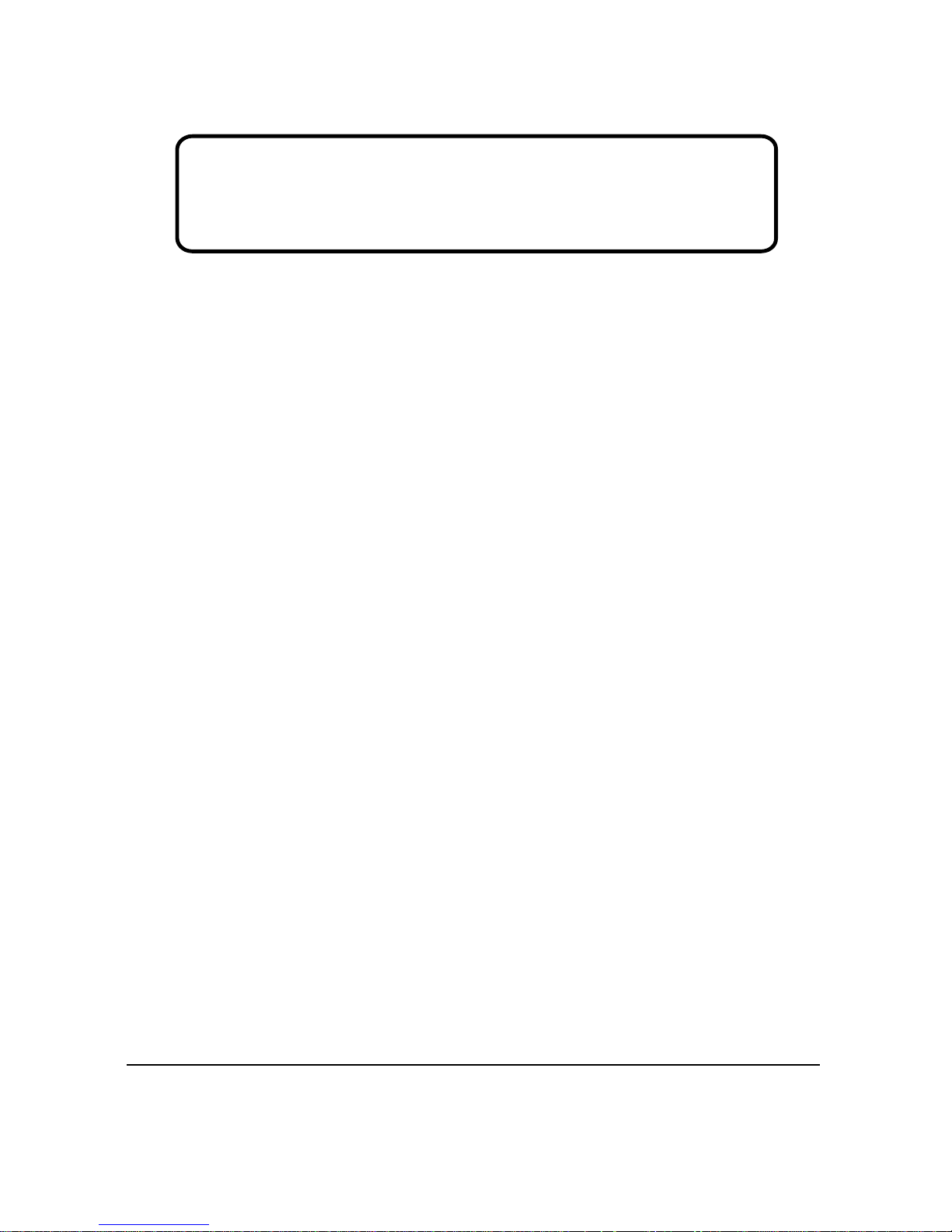
Correct Methods:
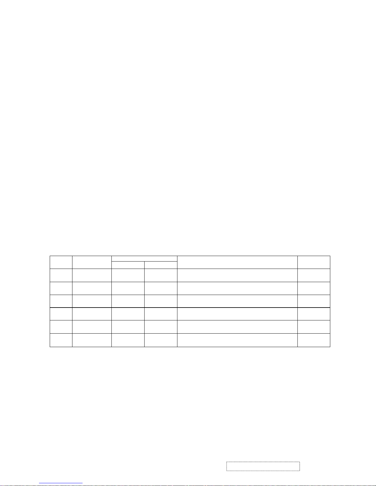
Incorrect Methods:
Only touch the metal frame of the LCD panel
or the front cover of the monitor.Do not
touch the surface of the polarizer.
Surface of the LCD panel is pressed by fingers and
that will probably cause “Mura”.
Take out the monitor with cushions Taking out the monitor by grasping the LCD
panel.That will probably cause “Mura”.
3
ViewSonic Corporation Confidential
-
Do Not Copy VE175-3
4
ViewSonic Corporation Confidential
-
Do Not Copy VE175-3
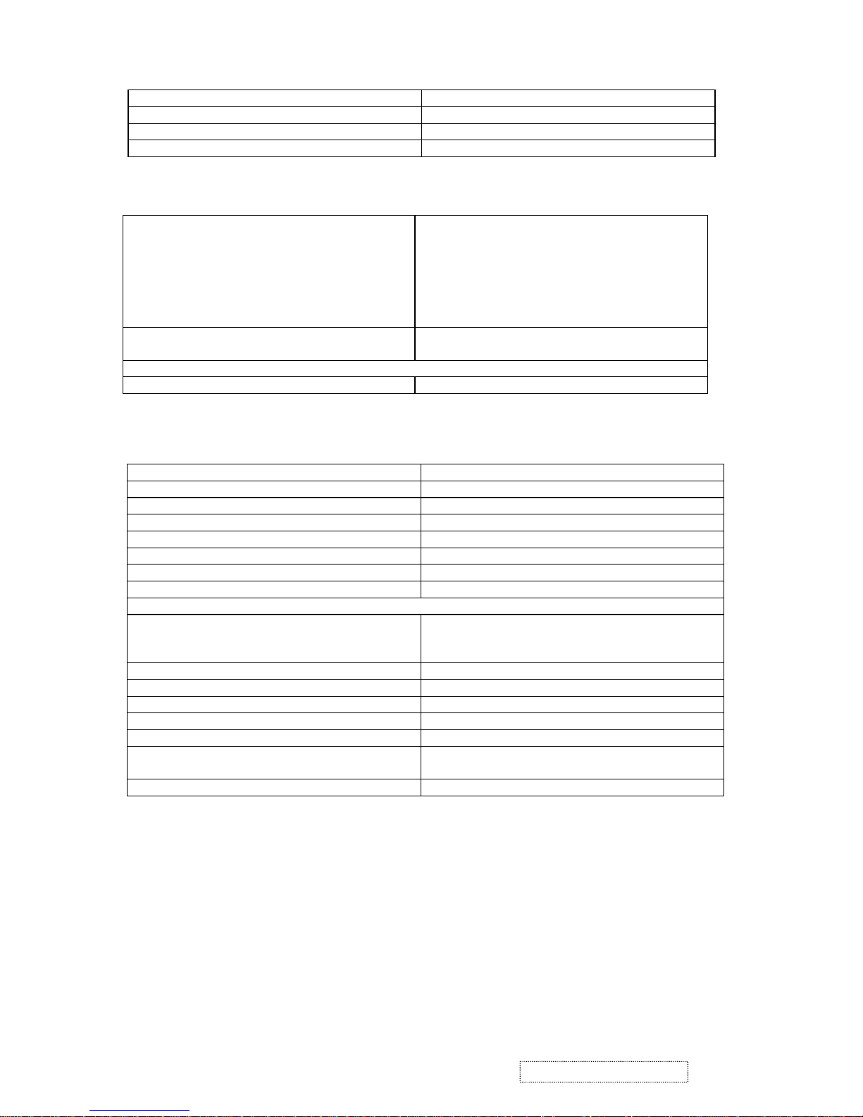
GENERAL specification
Test Resolution & Frequency 1280 x 1024 @ 60Hz
Test Image Size Full Size
Contrast and Brightness Controls
Factory Default:
Contrast = 50%, Brightness = 100%
VIDEO INTERFACE
Analog Input Connector DB-15 (Analog), refer the appendix A
Video Cable Strain Relief
Equal to twice the weight of the monitor for five
minutes
Video Cable Connector DB-15 Pin out Compliant DDC 1/2B
Video Signals Video RGB (Analog)
Video Impedance 75 Ohms (Analog), 100 Ohms (Digital)
Maximum PC Video Signal 950 mV with no damage to monitor
Maximum Mac Video Signal 1250 mV with no damage to monitor
Sync Signals TTL
DDC 1/2B Compliant with Revision 1.3
Sync Compatibility Separate Sync
Video Compatibility
Shall be compatible with all PC type computers,
Macintosh computers, and after market video cards
Resolution Compatibility
640 x 350, 640 x 480, 720 x 400 (640 x 400), 800
x 600, 832 x 624, 1024 x 768, 1280 x 1024
Exclusions Not compatible with interlaced video
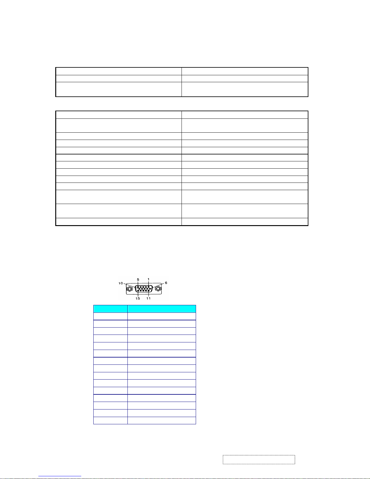
TABLE : 15 PIN D-SUB CONNECTOR PIN ASSIGNMENT
This section describes the pin assignment of the LCD’s video connector. It is called 15 Pin Mini D-sub Connector.
Pin NO. Signal Connector
1 Red Video Signal
2 Green Video Signal
3 Blue Video Signal
4 N.C.
5 Ground
6 Ground
7 Ground
8 Ground
9 +5v
10 Ground
11 N.C.
12 DDC data
13 Horizontal sync signal
14 Vertical sync signal
15 DDC clock
2. Specification
5
ViewSonic Corporation Confidential
-
Do Not Copy VE175-3
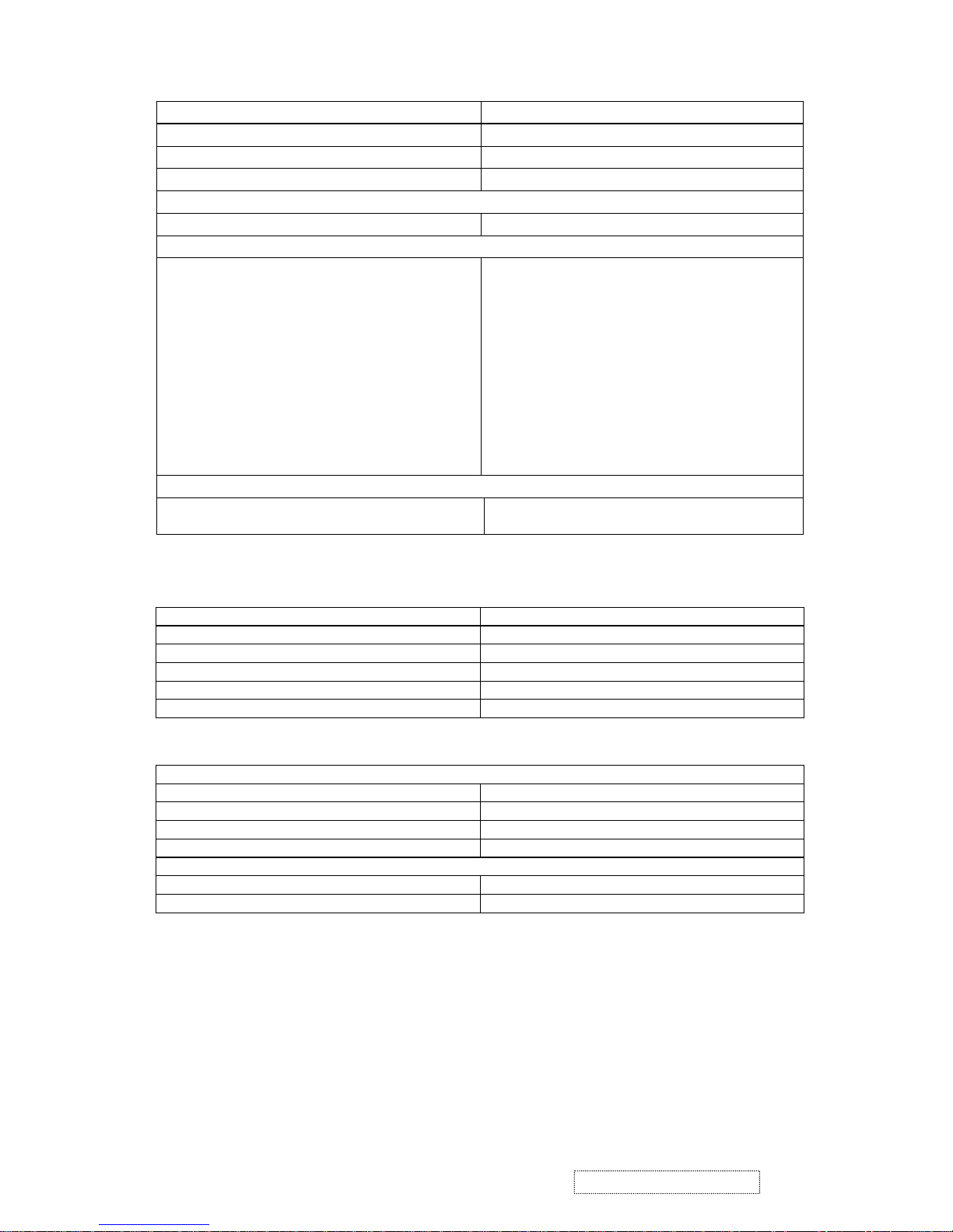
Changing Modes
Maximum Mode Change Blank Time, for image
stability. Note:
1) Excluding “Auto Adjust” time
2) Under DOS mode (640 x 350, 720 x 400 & 640
x 400), there is no “Auto Adjust” feature.
3) The monitor needs to do “Auto Adjust” the first
time a new mode is detected.
3 seconds (Max)
1 seconds (Typ) for recognized timings
1-2 seconds (Typ) for unrecognized timing
.
Mode Change Image The image shall blank while the monitor changes
modes.
GTF
GTF N/A
Panel Characteristics
Panel Type AUO M170EG01 V.1
Type COLOR ACTIVE MATRIX TFT, TN TYPE
Active Size 337.92 (H) x 270.336 (V)
Pixel Arrangement RGB Vertical Stripe
Pixel Pitch 0.264 mm
Glass Treatment Anti Glare (Hard coating 2H)
# of Backlights 4 CCFL edge-light (2 top / 2 bottom)
Backlight Life 50,000 Hours (Typ) /30,000 Hours (Min)
Panel Performance
Luminance –
Condition:
CT = 6500K, Contrast = Max, Brightness = Max
xxx cd/m2 (max after 30 minute warmup)
260 cd/m2 (typ after 30 minute warmup)
210 cd/m2 (min after 30 minute warmup)
Brightness Uniformity 75% Entire Area (minimum)
Contrast Ratio xxx:1 (max), 450:1 (typ), 250:1 (min)
Color Depth 16.2 million colors (8 bit panel)
Viewing Angle (Horizontal) 140 deg @ CR>10,
Viewing Angle (Vertical) 130 deg @ CR>10,
Response Time
10%-90% @ Ta=25°C
16 ms (Tr= 12 ms, Tf = 4 ms) (typ)
25ms (max)
Panel Defects Please see Panel Quality Specifications.
Power Supply
External Power Supply Part Number: HOAU222001
Input Voltage Range 90 to 264 VAC
Over Current Protection 5 A TYPICAL AT 5 VDC
Power Dissipation 45 Watts (typ)
6
ViewSonic Corporation Confidential
-
Do Not Copy VE175-3
Horizontal/Vertical Frequency
Horizontal Frequency 30-82 kHz
Vertical Refresh Rate 50 – 75 Hz.
Maximum Pixel Clock 140 MHz
Sync Polarity Independent of sync polarity.
Primary Presets
Primary Preset 1280 x 1024 @ 60Hz
Look up table timing
<<Analog>>
1. 640 x 350 @ 70Hz, 31.5kHz
2. 640 x 400 @ 70Hz, 31.5kHz
3. 640 x 480 @ 60Hz, 31.5kHz
4. 640 x 480 @ 67Hz, 35.0kHz
5. 640 x 480 @ 75Hz, 37.5kHz
6. 640 x 480 @ 72Hz, 37.9kHz
7. 720 x 400 @ 70Hz, 31.5kHz
8. 800 x 600 @ 56Hz, 35.1kHz
9. 800 x 600 @ 60Hz, 37.9kHz
10. 800 x 600 @ 75Hz, 46.9kHz
11. 800 x 600 @ 72Hz, 48.1kHz
12. 832 x 624 @ 75Hz, 49.7kHz
13. 1024 x 768 @ 60Hz, 48.4kHz
14. 1024 x 768 @ 70Hz, 56.5kHz
15. 1024 x 768 @ 72Hz, 58.1kHz
16. 1024 x 768 @ 75Hz, 60.0kHz
17. 1280 x 1024 @ 60Hz, 63.4kHz
18. 1280 x 1024 @ 75Hz, 79.97kHz
User Presets
Number of User Presets (recognized timings)
Available
10 presets total in FIFO configuration.
Dimensions (Base attached unless otherwise specified)
Width 414.5 mm
Height 403 mm
Depth 229 mm
Monitor Weight 5.7 kg /12.57lbs
Ergonomics
Tilt Up 20 degrees minimum
Tilt Down 5 degrees
Environmental Conditions
Operating Temperature 0°C to +40°C
Storage Temperature -20°C to +60°C
Operating Relative Humidity 20% to 90% RH Non-Condensing
Storage Relative Humidity 5% to 90% RH Non-Condensing
Operating Altitude 0 to +3,000 meters
Storage Altitude 0 to +12,000 meters
7
ViewSonic Corporation Confidential
-
Do Not Copy VE175-3
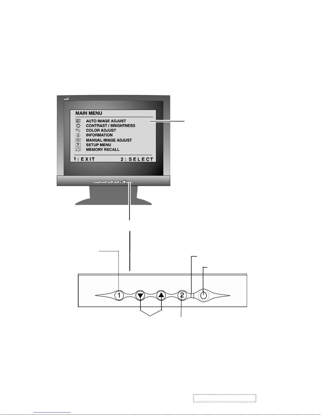
Adjusting the Screen Image
Use the buttons on the front control panel to display and adjust the OnView
®
controls which display on the screen. The OnView controls are explained at the
Front Control Panel
Main Menu
with OnView controls
Scroll through menu
options and adjust the
displayed control.
Displays, saves
changes to, and exits
the Main Menu.
Power On/Off
Selects a highlighted control. Also,
displays the control screen for the
selected control and toggles
between control pairs.
Power light
top of the next page.
3. Front Panel Function Control Description
8
ViewSonic Corporation Confidential
-
Do Not Copy VE175-3
. (The black border around the
edge of the screen should barely touch the illuminated “active area” of the
LCD dislay.)
Do the following to adjust the screen image:
1
To display the Main Menu, press button [1].
4
To adjust the control, press the upIor downJbuttons.
5
To save the adjustments and exit the menu, press button [1] twice.
The following tips may help you optimize your display:
• Adjust your computer's graphic card so that it outputs a video signal 1280 x
1024 @ 60 Hz to the LCD dislay. (Look for instructions on “changing the
refresh rate” in your graphic card's user guide.)
• If necessary, make small adjustments using H. POSITION and V. POSITION
until the screen image is completely visible
NOTE: All OnView menus and adjustment screens disappear automatically
menu and the OSD timeout control described on page 11.
2
To highlight a control you want to adjust, press I or J to scroll up or down
the Main Menu.
3
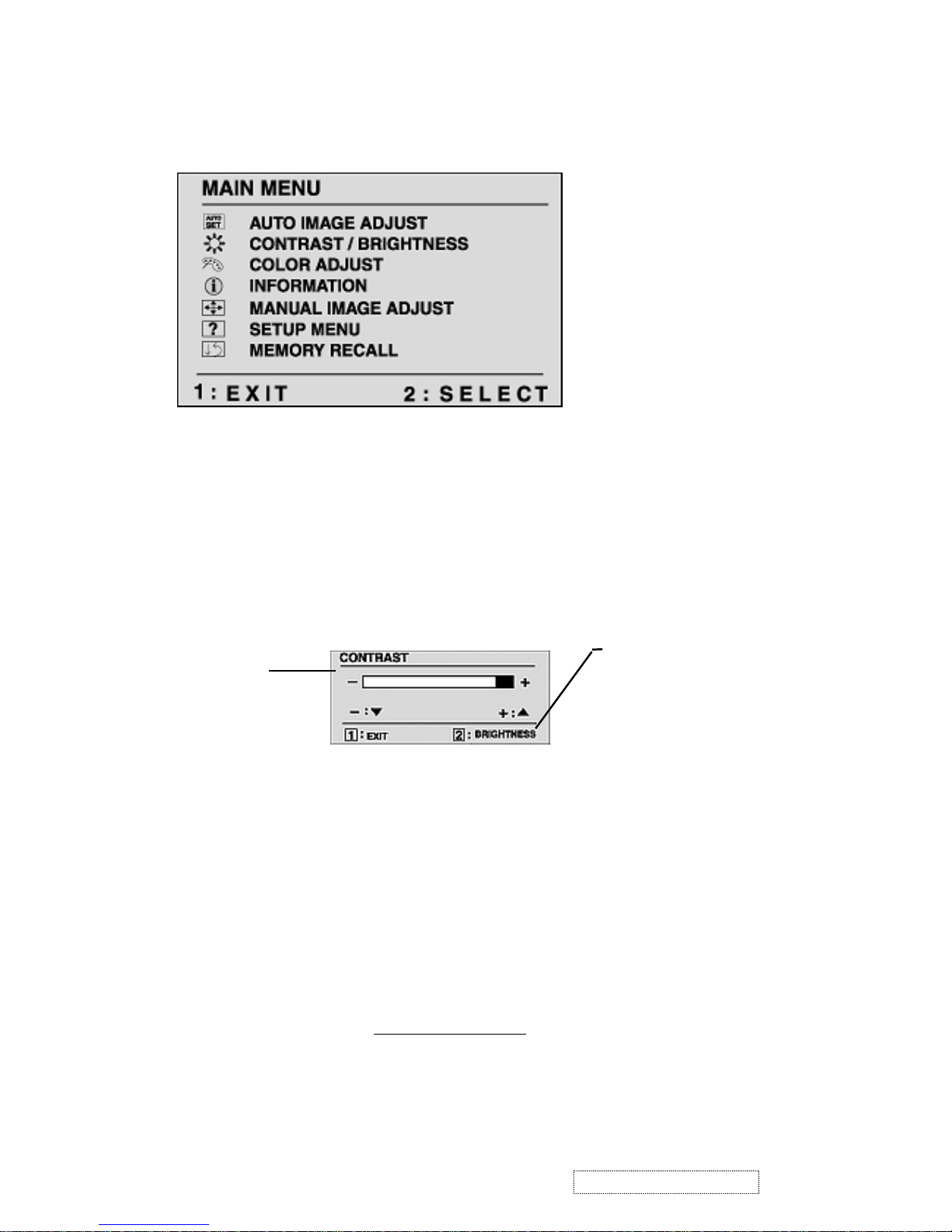
To select the highlighted control, press button [2]. A control screen appears
like the example shown below.
after about 30 seconds. This time period is adjustable through the Setup
TheJdown
arrow decreases,
I
up arrow
increases
The line at the
bottom of the screen
tells you what you
can do next - in this
example, either EXIT
or select the
BRIGHTNESS
control.
9
ViewSonic Corporation Confidential
-
Do Not Copy VE175-3
Main Menu Controls
Adjust the menu items shown below by using the up Iand down Jbuttons.
Control Explanation
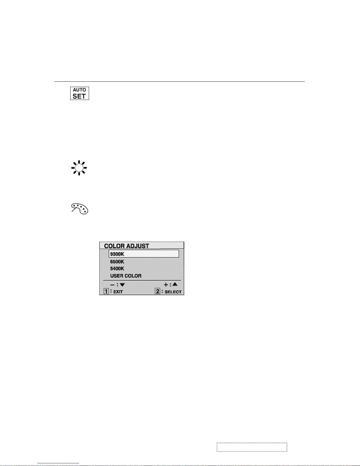
Auto Adjust
automatically sizes, centers, and fine tunes the
video signal to eliminate waviness and distortion.
Press the [2] button to obtain a sharper image.
NOTE
: Auto Adjust works with most common video cards. If
this function does not work on your LCD dislay, then lower the
video refresh rate to 60 Hz and set the resolution to its pre-set
value.
Contrast
adjusts the difference between the image background
(black level) and the foreground (white level).
Brightness
adjusts background black level of the screen image.
Color Adjust
provides several color options: preset color
temperatures and User which allows you to adjust red (R), green
(G), and blue (B). The factory setting for this product is 6500K
(6500 Kelvin).
6500K
— Adds red to the screen image for warmer white and
richer red. Default setting.
9300K
— Adds blue to the screen image for cooler white (used
in most office settings with fluorescent lighting).
5400K — Adds green to the screen image for a darker color.
1
To select color (R, G or B) press button [2].
2
To adjust selected color, press I or J.
3
When you are finished making all color adjustments, press
button [1] twice.
User
— Individual adjustments for red, green, and blue.
10
ViewSonic Corporation Confidential
-
Do Not Copy VE175-3
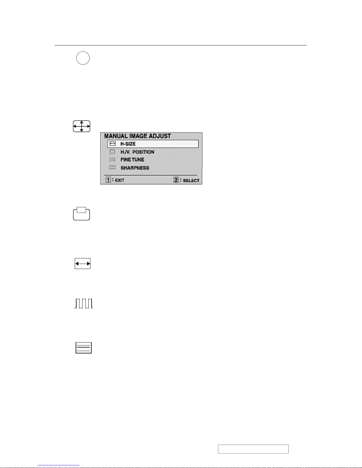
Information
displays the timing mode (video signal input)
coming from the graphics card in your computer. See your
graphic card’s user guide for instructions on changing the
resolution and refresh rate (vertical frequency).
VESA 1280 x 1024 @ 60 Hz (recommended) means that the
resolution is 1280 x 1024 and the refresh rate is 60 Hertz.
Control Explanation
i
H. Size
(Horizontal Size) adjusts the width of the screen image.
NOTE:
Vertical size is automatic with your LCD dislay.
H./V. Position
adjusts horizontal and vertical position of the
screen image. You can toggle between Horizontal and Vertical
by pressing button [2]. Horizontal moves the screen image to
the left or to the right. Vertical moves the screen image up and
down.
Manual Image Adjust
The Manual Image Adjust controls are explained below:
Fine Tune sharpens focus by aligning the illuminated text and/
or graphic characters.
NOTE: Try the Auto Adjust (see page 9) before using the Fine
Tune control.
Sharpness
adjusts the clarity and focus of the screen image.
11
ViewSonic Corporation Confidential
-
Do Not Copy VE175-3
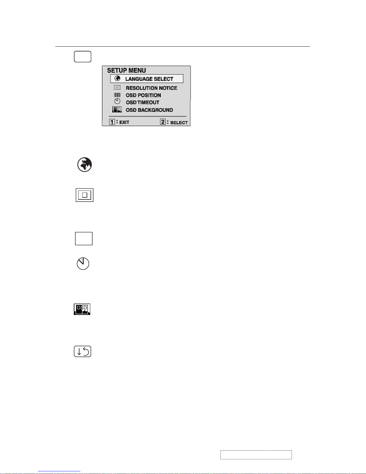
Setup Menu displays the menu shown below.
Explanation
the menus and control screens.
The Setup Menu controls are explained below.
OSD Position
allows you to move the on-screen display menus
and control screens.
OSD Timeout
sets the length of time an on-screen display
screen is displayed. For example, with a “15 second” setting, if
a control is not pushed within 15 seconds, the display screen
disappears.
L
anguage
Select allows you to choose the language used in
OSD
?
Control
Resolution Notice
advises the optimal resolution to use. After
selecting Resolution Notice, a sub menu appears asking if you
want to Disable or Enable the notice. If you want the Resolution
Notice to appear on-screen, select Enable.
Memory Recall
returns adjustments to the original factory
settings if the display is operating in a factory Preset Timing
Mode listed in this user guide.
OSD Background
allows you to turn the On-Screen display
background on or off. This means that while making adjustments
from the OSD control screens you can also view open software
applications, or the Windows desktop.
12
ViewSonic Corporation Confidential
-
Do Not Copy VE175-3
Hot Key for Function Controls
Buttons: Functions:
[Up] + [Down] arrows Recall Contrast or Brightness while in the
Contrast or Brightness adjustment.or recall both
of Contrast and Brightness when the OSD in not
on.
[1] + [2] Toggle 720x400 and 640x400 mode when input
720x400 or 640x400 mode.
[1] + [Up] + [Down] White Balance.White Balance should set the
screen on the pure black and white pattern with
640x480@60Hz
resolution.
[1] + [Down] (hold for 10 seconds) Power Lock (Unlock).User won’t be able to turn
off the monitor.
[1] +[Up] (hold for 10 seconds) OSD Lock (Unlock).
Then press [Up] key at the same time and plug the
AC cord.
All Mode Reset. It will erase all end user’s setting
and restore the factory defaults.
un-plug the AC cord and be sure the signal cable
is
not connected (D-sub not
connected) , then press
[2] key at the same time and plug the AC cord.
Burn in Mode
. After entering Burn in Mode. press
[1] button. you can find the information about this
monitor.
un-plug the AC cord and be sure the signal cable
,
then press [
2] key at the same time and plug the
AC cord.
Factory in Mode.
13
ViewSonic Corporation Confidential
-
Do Not Copy VE175-3

1. WORKING THEOREM
A. DC-DC CONVERTER
This brick converts the 5V input voltage to 3.3V and 1.8V for controller use.
It consists of a Liner Regulator IC (AIC117), filter capacitor, and constant voltage capacitor. The AIC1117 is
a low dropout three terminal regulator with 800mA output current capability. Its low dropout voltage and fast
transient response make it ideal for low voltage microprocessor applications. Internal current and thermal limiting
provides protection against any overload condition that would create excessive junction temperatures.
B. A/D converter
The gmZAN3SL provides all the key display functions required for displaying a good quality image on a LCD
panel when connected to the PC source with analog interface. The integrated functions include a high-speed triple-ADC
and PLL, a high quality zoom and shrink scaling engine, an on-screen display (OSD) controller, digital color controls
and LVDS Transmitters. Its provides a front-end analog interface with standard VGA compliance and an output industry
standard LVDS interface for speed grade up to XGA and SXGA respectively. Typical gmZAN3SL based design need an
external 8051 equivalent MCU with integrated flash. It provides the flexibility of choosing either 8bit parallel or 6wire
host interface. Integrated LVDS transmitters and PWM based backlight control circuitry provides direct interconnect to
LCD panels and backlight inverters. Integrated Schmitt circuit, integrated reset circuit and single crystal base makes
gmZAN3XL/SL an ideal choice for the entry- level SXGA monitor design.
D. MCU:
The MTV312M micro-controller is an 8051 CPU core embedded device especially tailored for CRT/LCD Monitor
applications. It includes an 8051 CPU core, 1024-byte SRAM, 14 built-in PWM DACs, VESA DDC interface,
4- channel A/D converter, and a 64K-byte internal program Flash-ROM.
4. Circuit Description
14
ViewSonic Corporation Confidential
-
Do Not Copy VE175-3
 Loading...