

Page 1

Model No. VLCDS23585-1W
15” Color TFT LCD Display
Service Manual
ViewSonic VE155s
ViewSonic
381 Brea Canyon Road, Walnut, California 91789 USA - (800) 888-8583
(VE155s-1_SM_699, VE500-5_SM_700, VE155/b_SM_531, VA520-2_SM_559 - Rev. 1b- Jul. 2003) v. 1b – 07 2003)
VE500-2
VE155
VA520-2
VLCDS23585-2W
VLCDS23585-3W
VE155b
(MRT MASCOT VZ Scalar) )VLCDS23585-
Page 2
Copyright
Copyright
¤
2003 by ViewSonic Corporation. All rights reserved. No part of this publication may be
reproduced, transmitted, transcribed, stored in a retrieval system, or translated into any language or
computer language, in any form or by any means, electronic, mechanical, magnetic, optical, chemical,
manual or otherwise, without the prior written permission of ViewSonic Corporation.
Disclaimer
ViewSonic makes no representations or warranties, either expressed or implied, with respect to the
contents hereof and specifically disclaims any warranty of merchantability or fitness for any particular
purpose. Further, ViewSonic reserves the right to revise this publication and to make changes from time
to time in the contents hereof without obligation of ViewSonic to notify any person of such revision or
changes.
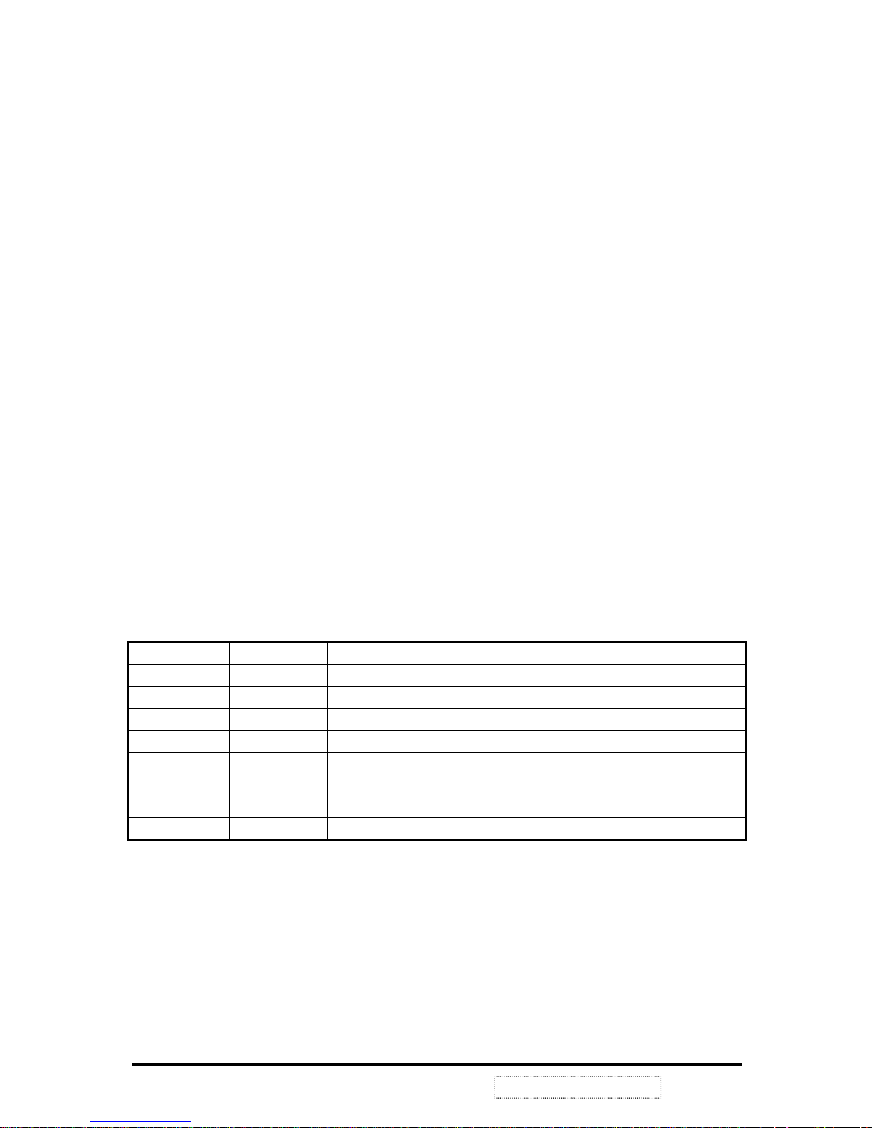
Revision History
Revision Date Description Of Changes Approval
1a 06/08/02 Initial Release DCN- 2228, 2324 SEARST
!
!
ViewSonic Corporation
i
Confidential –DoNotCopy
VE155s, VE500-2
Trademarks
ViewSonic is a registered trademark of ViewSonic Corporation.
All other trademarks used within this document are the property of their respective owners.
Optiquest is a registered trademark of ViewSonic Corporation.
VE155/b, VA520-2
1b 07/30/03 Revise DCN- 3502/3503,3612/3613 Fellen. Fan
Page 3

TABLE OF CONTENTS
1. Precautions and Notices...................................................................................
1
2. Specification ......................................................................................................
2
3. Control Location and Functions ......................................................................
6
4. Circuit Description ............................................................................................
12
5. Adjusting Procedure............................................................................................
13
6. Trouble Shooting Flow Chart ..........................................................................
15
7. Exploded Diagram................................................................................................
17
8. Exploded Parts List.............................................................................................
18
9. Block Diagram ...................................................................................................
20
10. Schematic Diagram ..........................................................................................
21
11. PCB Layout .......................................................................................................
27
12. Recommend Spare Parts List..……………………………………………………
31
13. Electrical Parts List …………………………………………………………………. 33
!
!
ViewSonic Corporation
ii
Confidential –DoNotCopy
VE155s, VE500-2
VE155/b, VA520-2
Page 4

1. PRECAUTION AND SAFETY NOTICES
1.1. SAFETY PRECAUTIONS
This monitor is manufactured and tested on a ground principle that a user's safety comes first.
However, improper use or installation may cause damage to the monitor as well as to the user.
Carefully go over the following WARNINGS before installing and keep this guide handy.
WARNINGS:
This monitor should be operated only at the correct power sources indicated on the label
on the rear end of the monitor. If you're unsure of the power supply in your residence,
consult your local dealer or power company.
Do not try to repair the monitor your self as it contains no user-serviceable parts. This
monitor should only be repaired by a qualified technician.
Do not remove the monitor cabinet. There is high-voltage parts inside that may cause
electric shock to human bodies, even when the power cord is unplugged.
Stop using the monitor if the cabinet is damaged. Have it checked by a service technician.
Put your monitor only in a clean, dry environment. If it gets wet, unplug the power cable
immediately and consult your service technician.
Always unplug the monitor before cleaning it. Clean the cabinet with a clean, dry cloth.
Apply non-ammonia based cleaner onto the cloth, not directly onto the glass screen.
Keep the monitor away from magnetic objects, motors, TV sets, and transformer.
Do not place heavy objects on the monitor or power cord.
1.2. PRODUCT SAFETY NOTICE
Many electrical and mechanical parts in this chassis have special safety visual inspections and
the protection afforded by them cannot necessarily be obtained by using replacement
components rated for higher voltages, wattage, etc. Before replacing any of these
components read the parts list in this manual carefully. The use of substitute replacement
parts which do not have the same safety characteristics as specified in the parts list may create
shock, fire, or other hazards.
1.3. SERVICE NOTES
1. When replacing parts or circuit boards, clamp the lead wires around terminals before
soldering.
2. When replacing a high wattage resistor (more than 1W of metal oxide film resistor) in
circuit board, keep the resistor about 5mm away from circuit board.
3. Keep wires away from high voltage, high temperature components and sharp edges.
4. Keep wires in their original position so as to reduce interference.
5. Usage of this product please refer to also user's manual.
!
!
ViewSonic Corporation
1
Confidential –DoNotCopy
VE155s, VE500-2
VE155/b, VA520-2
Page 5

2. SPECIFICATION
2.1. PRODUCT SPECIFICATION
LCD Panel 15.0" TFT
Power Management Energy Star compliant VESA
DPMS compatible
< 2W
Displayable Resolution XGA 1024× 768 (max.)
Pixel Dimension 0.297× 0.297mm
LCD Display Color 16.7M Color Max. (8bit)
Viewing Angle CR
≧10
Horizontal: -60°+60°
Vertical: -45°+55°
Tilt +90°, -5°
Contrast Ratio 200 : 1 (min)
400 : 1 (typ.)
Brightness 200cd/ m2 (min.)
250 cd/m2 (typ.)
Response Time Tr: 7 ms Tf: 23ms (typ.)
Active Display Area 304.1mm× 228.1mm
Temperature Operating: 0°C ~ +35°C
Storage: -20°C ~ +60°C
Compliance UL, CUL, TÜV/GS, TÜV/Ergo, CE, FCC-B, Energy Star,
Power Input Voltage: 100~240 Vac
Consumption: 30 Watts (Max.)
!
!
ViewSonic Corporation
2
Confidential –DoNotCopy
VE155s, VE500-2
VE155/b, VA520-2
VCCI, BSMI, GOST-R, TCO'99 and CCC.
Page 6

2.2. SUPPORTING TIMING CHART
ITEM 1 2 3 4 5
TIMING 640×350@70
Hz
720×400@70
Hz
640×480@60
Hz
640×480@67
Hz
640×480@72
Hz
Pixel Rate 25.175MHz 28.322MHz 25.175MHz 30.240MHz 31.500MHz
H TOTAL 31.778us 31.778us 31.778us 28.571us 26.413us
H
DISPLAY
25.422us 25.422us 25.422us 21.164us 20.317us
H B-Porch 1.907us 1.907us 1.907us 3.175us 4.063us
H Width 3.813us 3.813us 3.813us 2.116us 0.270us
H Border 0.318us 0.318us 0.318us 0.000us 0.000us
V TOTAL 14.268ms 14.268ms 16.683ms 15.000ms 13.734ms
V
DISPLAY
11.122ms 12.711ms 15.253ms 13.714ms 12.678ms
V B-Porch 1.907ms 1.112ms 1.049ms 1.114ms 0.528ms
Vs Width 0.064ms 0.064ms 0.064ms 0.086ms 0.079ms
V Border 0.191ms 0.222ms 0.254ms 0.000ms 0.000ms
H/V Sync +/- -/+ -/- -/- -/Interlace No. No. No. No. No.
ITEM 6 7 8 9 10
TIMING 640×480@75
Hz
800×600@56
Hz
800×600@60
Hz
800×600@72
Hz
800×600@75
Hz
Pixel Rate 31.500MHz 36.000MHz 40.000MHz 50.000MHz 48.500MHz
H TOTAL 26.667us 28.444us 26.400us 20.800us 21.333us
H
DISPLAY
20.317us 22.222us 20.000us 16.000us 16.162us
H B-Porch 3.810us 3.556us 2.200us 1.280us 3.232us
H Width 2.032us 2.000us 3.200us 2.400us 1.616us
H Border 0.000us 0.000us 0.000us 0.000us 0.000us
V TOTAL 13.334ms 17.778ms 16.579ms 13.853ms 13.333ms
V
DISPLAY
12.800ms 17.066ms 15.840ms 12.480ms 12.800ms
V B-Porch 0.427ms 0.626ms 0.607ms 0.478ms 0.448ms
Vs Width 0.080ms 0.057ms 0.106ms 0.125ms 0.064ms
V Border 0.000ms 0.000ms 0.000ms 0.000ms 0.000ms
H/V Sync -/- +/+ +/+ +/+ +/+
Interlace No. No. No. No. No.
!
!
ViewSonic Corporation
3
Confidential –DoNotCopy
VE155s, VE500-2
VE155/b, VA520-2
Page 7

ITEM 11 12 13 14 15
TIMING 832×624@74.5
Hz
1024×768@60
Hz
1024×768@70
Hz
1024×768@7
2Hz
1024×768@7
5Hz
Pixel Rate 57.280MHz 65.000MHz 75.000MHz 77.066MHz 78.750MHz
H TOTAL 20.112us 20.677us 17.707us 17.232us 16.660us
H
DISPLAY
14.525us 15.754us 13.653us 13.287us 13.003us
H B-Porch 3.771us 2.462us 1.920us 1.869us 2.235us
H Width 1.118us 2.092us 1.813us 1.765us 1.219us
H Border 0.000us 0.000us 0.000us 0.000us 0.000us
V TOTAL 13.417ms 16.666ms 14.272ms 13.889ms 13.328ms
V
DISPLAY
12.552ms 15.880ms 13.599ms 13.234ms 12.795ms
V B-Porch 0.784ms 0.600ms 0.513ms 0.500ms 0.466ms
Vs Width 0.060ms 0.124ms 0.106ms 0.103ms 0.050ms
V Border 0.00ms 0.000ms 0.000ms 0.000ms 0.000ms
H/V Sync -/- -/- -/- -/- +/+
Interlace No. No. No. No. No.
ITEM 16
TIMING 1024×768@75
Hz
Pixel Rate 80.0000MHz
H TOTAL 16.600us
H
DISPLAY
12.800us
H B-Porch 2.200us
H Width 1.200us
H Border 0.000us
V TOTAL 13.346ms
V
DISPLAY
12.749ms
V B-Porch 0.498ms
Vs Width 0.050ms
V Border 0.000ms
H/V Sync -/-
Interlace No.
!
!
ViewSonic Corporation
4
Confidential –DoNotCopy
VE155s, VE500-2
VE155/b, VA520-2
Page 8
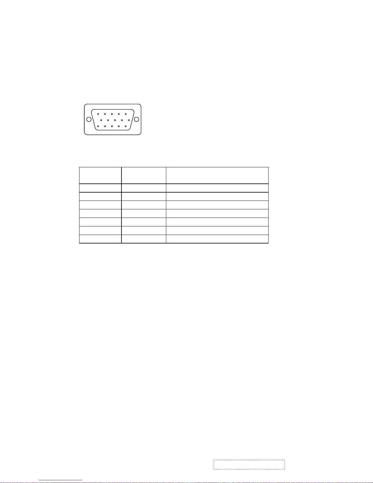
2.3. D-SUB CONNECTOR
D-SUB 15 PIN CONNECTOR
SIGNAL LEVEL
CONNECTOR SIGNAL DESCRIPTION
R RED 0.7vp-p(VIDEO)
G GREEN 0.7vp-p(VIDEO)
B BLUE 0.7vp-p(VIDEO)
H H/SYNC TTL positive or negative
V V/SYNC TTL positive or negative
SDA DDC1/2B TTL
SCL DDC1/2B TTL
1 2345
678910
11 12 13 14 15
1.R 6.GND 11.NC
2.G 7.GND 12.SDA
3.B 8.GND 13.H.SYNC
4.NC 9. +5V 14.V.SYNC
5.GND 10.GND 15.SCL
!
!
ViewSonic Corporation
5
Confidential –DoNotCopy
VE155s, VE500-2
VE155/b, VA520-2
Page 9
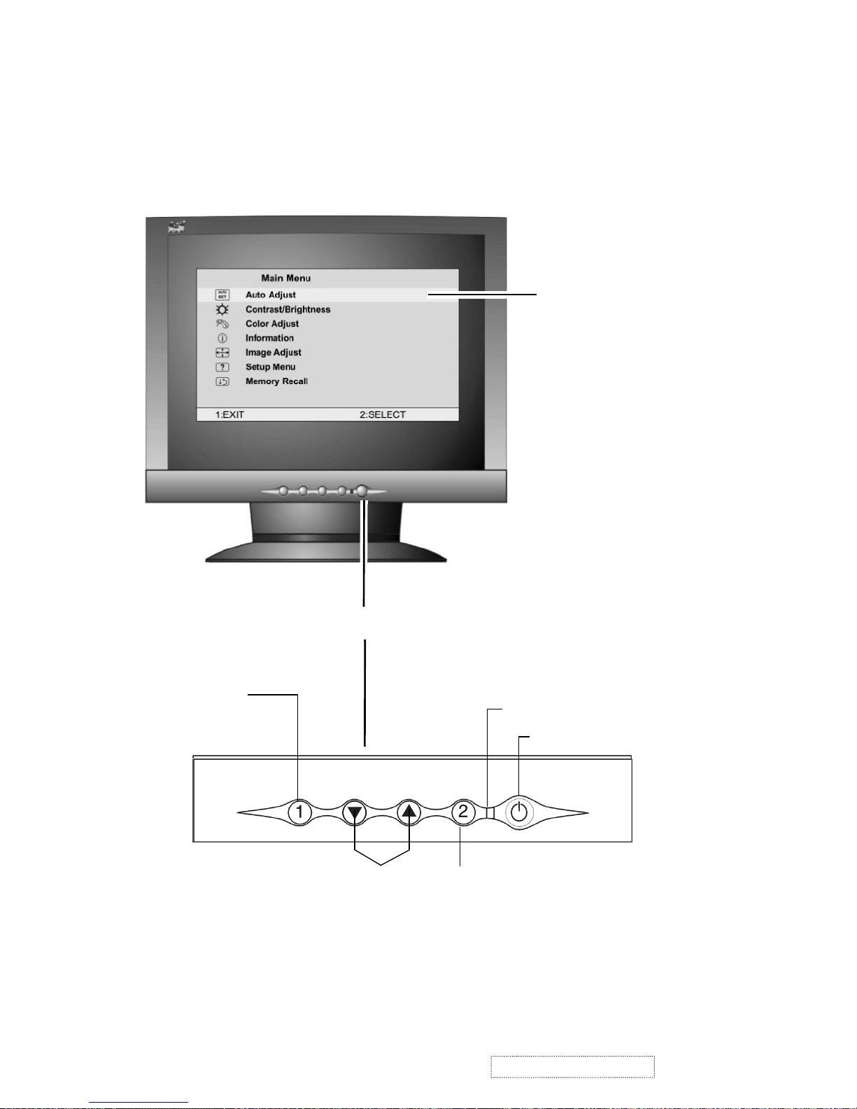
3. Front Panel Function Control Description
Scroll through menu
options and adjust the
displayed control.
Displays, saves
changes to, and exits
the Main Menu.
Power On/Off
Selects a highlighted control. Also,
displays the control screen for the
selected control and toggles
between control pairs.
Power light
Front Control Panel
Main Menu
with OnView controls
!
!
ViewSonic Corporation
6
Confidential –DoNotCopy
VE155s, VE500-2
VE155/b, VA520-2
Page 10
. (The black border around the
edge of the screen should barely touch the illuminated “active area” of the
LCD display.)
The line at the
bottom of the
screen tells you
what you can do
next: Exit or Select
the control that is
highlighted.
Main Menu
1:EXIT 2:SELECT
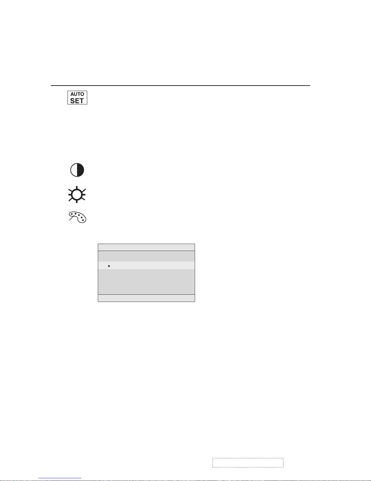
Auto Adjust
Contrast/Brightness
Color Adjust
Information
Image Adjust
Setup Menu
Memory Recall
AUTO
SET
i
?
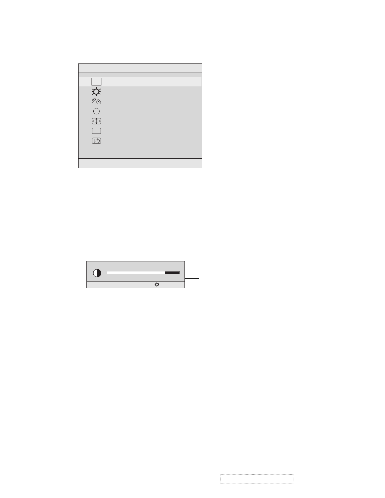
Do the following to adjust the screen image:
1
To display the Main Menu, press button [1].
4
To adjust the control, press the up I or down J buttons.
5
To save the adjustments and exit the menu, press button [1] twice.
The following tips may help you optimize your display:
• Adjust your computer's graphic card so that it outputs a video signal 1024 x
768 @ 60 Hz to the LCD display. (Look for instructions on “changing the
refresh rate” in your graphic card's user guide.)
• If necessary, make small adjustments using H. POSITION and V. POSITION
until the screen image is completely visible
NOTE: All OSD menus and adjustment screens disappear automatically
after about 15 seconds. This time period is adjustable through the Setup
menu and the OSD timeout control described on page 11.
2
To highlight a control you want to adjust, press I or J to scroll up or down
the Main Menu.
3
To select the highlighted control, press button [2]. A control screen appears
like the example shown below.
Contrast
1:EXIT 2: Brightness
!
!
ViewSonic Corporation
7
Confidential –DoNotCopy
VE155s, VE500-2
VE155/b, VA520-2
Page 11
Main Menu Controls
Adjust the menu items shown below by using the up Iand down Jbuttons.
Control Explanation
Auto Adjust
automatically sizes, centers, and fine tunes the
video signal to eliminate waviness and distortion.
Press the [2] button to obtain a sharper image.
NOTE
: Auto Adjust works with most common video cards. If
this function does not work on your LCD display, then lower the
video refresh rate to 60 Hz and set the resolution to its pre-set
value.
Contrast
adjusts the difference between the image background
(black level) and the foreground (white level).
Brightness
adjusts background black level of the screen image.
Color Adjust
provides several color options: preset color
temperatures and User which allows you to adjust red (R), green
(G), and blue (B). The factory setting for this product is 6500K
(6500 Kelvin).
1
To select color (R, G or B) press button [2].
2
To adjust selected color, press I or J.
3
When you are finished making all color adjustments, press
button [1] twice.
Color Adjust
1:EXIT 2:SELECT
9300K
6500K
User Color
6500K
— Adds red to the screen image for warmer white and
richer red. Default setting.
User
— Individual adjustments for red, green, and blue.
9300K
— Adds blue to the screen image for cooler white (used
in most office settings with fluorescent lighting).
!
!
ViewSonic Corporation
8
Confidential –DoNotCopy
VE155s, VE500-2
VE155/b, VA520-2
Page 12
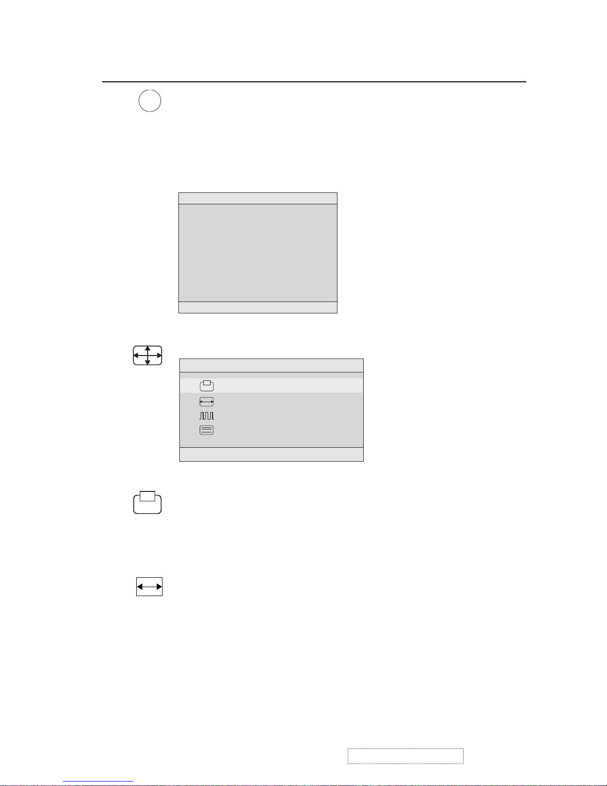
Information
displays the timing mode (video signal input)
coming from the graphics card in your computer. See your
graphic card’s user guide for instructions on changing the
resolution and refresh rate (vertical frequency).
VESA 1024 x 768 @ 60 Hz (recommended) means that the
resolution is 1024 x 768 and the refresh rate is 60 Hertz.
Control Explanation
i
H. Size
(Horizontal Size) adjusts the width of the screen image.
NOTE:
Vertical size is automatic with your LCD display.
H./V. Position
adjusts horizontal and vertical position of the
screen image. You can toggle between Horizontal and Vertical
by pressing button [2]. Horizontal moves the screen image to
the left or to the right. Vertical moves the screen image up and
down.
Information
1:EXIT
H. Frequency: 48.60 KHz
V. Frequency: 60.00 Hz
Pixel Clock: 65.00 MHz
Resolution: 1024 x 768
Model Number: VLCDS23585-2W
Serial No:
www.viewsonic.com
Image Adjust
The Image Adjust controls are explained below:
Image Adjust
1:EXIT 2:SELECT
H./V. Position
H. Size
Fine Tune
Sharpness
!
!
ViewSonic Corporation
9
Confidential –DoNotCopy
VE155s, VE500-2
VE155/b, VA520-2
Page 13
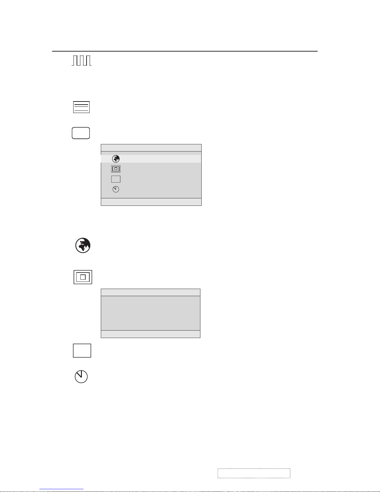
Fine Tune sharpens focus by aligning the illuminated text and/
or graphic characters.
NOTE: Try the Auto Adjust (see page 9) before using the Fine
Tune control.
Sharpness
adjusts the clarity and focus of the screen image.
Setup Menu displays the menu shown below.
Control Explanation
Setup Menu
1:EXIT 2:SELECT
Language Select
Resolution Notifier
OSD Position
OSD Timeout
OSD
Resolution Notice
For best picture quality
change the resolution to
1024 x 768
1:EXIT 2:DISABLE
the menus and control screens.
The Setup Menu controls are explained below.
OSD Position
allows you to move the on-screen display menus
and control screens.
OSD Timeout
sets the length of time an on-screen display
screen is displayed. For example, with a “15 second” setting, if
a control is not pushed within 15 seconds, the display screen
disappears.
Resolution Notice
advises the optimal resolution to use.
L
anguage
Select allows you to choose the language used in
OSD
?
!
!
ViewSonic Corporation
10
Confidential –DoNotCopy
VE155s, VE500-2
VE155/b, VA520-2
Page 14
Memory Recall
returns adjustments to the original factory
settings if the display is operating in a factory Preset Timing
Mode listed in this user guide.
Control Explanation
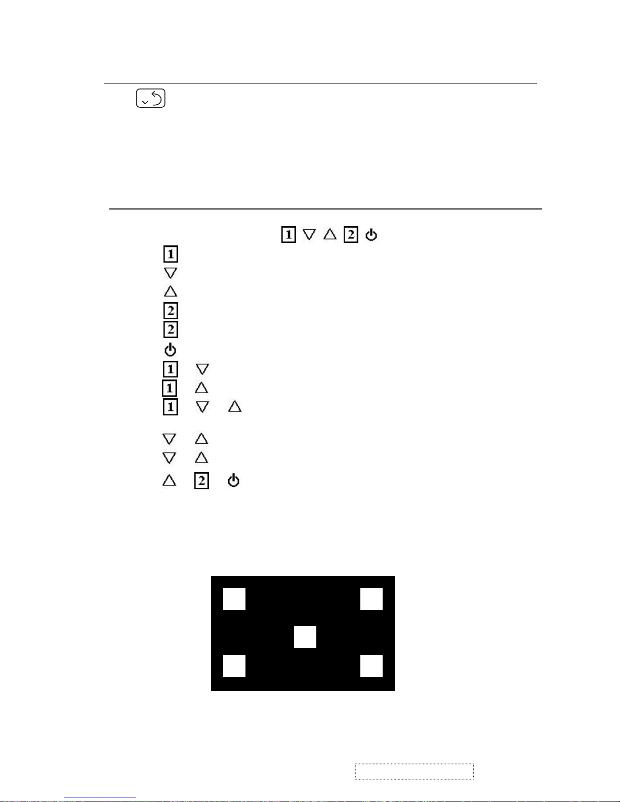
Short Cut Key
!
!
ViewSonic Corporation
11
Confidential –DoNotCopy
Function Key : 5 Key à
: Show OSD Menu or Exit OSD Menu.
: Select down or decrease.(-)
:Select up or increase(+).
: Select Or Enter.
: Auto adjust. (When No OSD)
: Power On/Off.
+ = Power key lock / unlock.
+ = OSD lock / unlock.
+ + = Auto White Balance.
(Remark: recommend to use 5-Disc full white pattern)
+ = Recall Contrast and Brightness. (Don’t show OSD)
+ + No Signal = Enter Burn in mode
+ + (Power On) = Enter Maintain mode.
5-Disc full white Patten
VE155s, VE500-2
VE155/b, VA520-2
Page 15

4. Circuit Description
A.
DC-DC CONVERTER
This block provides adjustable output voltages of 9.2V, -6V, 18V and 3 to 4V for the panel.
It consists of a Q114 transistor and power switch IC I108 (AIC 1526-1).
When DC_ EN signal is high, then Q114 is activated and sends one signal to activate I108.
At this time I108 will send 200KHz 12V PWM to Q106, Which is connected with L111, Q106,
D203 and C308, to boost 5V to 9.2V. And I108 offers the adjustable voltage of 3V to 4V. By
sending out pulses from pin 2 and pin 16 of I108 to double voltage circuit consisting of C301,
D201, D202 and C303, linear regulator with Q105, would output –6V, 18V output is created,
according to the rule of –6V creation.
B.
Scalaring controller
MascotV scalar is a highly integrated solution that combines a high performance ADC with an
advanced image processing controller. Using advanced image scaling algorithms, Mascot V has
intelligently adaptive sub-algorithms that will automatically optimize the display quality for
different images – the text is sharper and the graphics are smoother. The built-in analog interface
includes a 160Mhz, 8-bit 3-channel ADC, preamplifier, and VGA, allowing seamless support
to resolutions from VGA to XGA. MascotV also offers other integrated functions such as an
internal OSD that supports all languages, and built-in line buffers that allow support for a wide
range of LCD panels.
The scalar implements four advanced display technologies:
1. Sampling RGB input signals by fully integrated triple-channel ADC, PLL, and pre-amplifier
2. Automatically calibrate for vertical and horizontal alignment to center display and phase
calibration
3. High-quality advanced scaling: Enhanced and adaptive scaling algorithm for optimal image
quality
4. One and two pixels per clock panel support: Up to 24 bits per pixel.
The panel interface consists of 48-bit panel data bus, Start Pulse(STH1) and Clock (CLKH),
Polarity(POL)/Latch pulse(LP) for source driver IC, Start pulse(STV1) and Clock(CLKV) for
gate driver IC, and Data inversion control(HMSO/HMSE) for odd/even pixel bus and the
power supply
(+3.2V, +3.45V<adjustable>,+9.2V, +18Vand-6V) for panel driver IC use.
C.
Inverter
In order to drive the CCFLs embedded in the panel module, there is a ROYER inverter to
convert the input 12Vdc up to more than 600Vac.
The inverter is formed by symmetric outputs, in order to drive the separate lamp modules.
The input stage consists of a PWM controller, buck choke, and switching MOSFET to convert
DC input into AC output.
The output stage consists of a tuning capacitor, transformer, push-pull transistor pair and one
resister is serial to lamp for output cuttent feedback.
A 5-pin connector is the only interface to control
the inverter. Pin 1 is 12V input, Pin 2/4 are the
returns, pin3 is the control of output current, and pin 5 is the enable/disable control.
!
!
ViewSonic Corporation
12
Confidential –DoNotCopy
VE155s, VE500-2
VE155/b, VA520-2
Page 16

5. Adjusting Procedure
5.1. ADJUSTMENT CONDITIONS AND PRECAUTIONS
1. Approximately 30 minutes should be allowed for warm up before proceeding.
2. Adjustments should be undertaken only on those necessary elements since most of them
have been carefully preset at the factory.
3. ESD protection is needed before adjustment.
5.2. MAIN ADJUSTMENTS
NO. FUNCTION DESIGNATION
1. V-com Voltage R124 (VCOM ADJ)
2. Eeprom Initial Function Key
3. White Balance Function Key
4. Geometry Function Key
5.3. ALIGNMENT PROCEDURES
Adjustment Conditions and Precautions:
(A). Power supply voltage:
AC 110/120V±10% 60 Hz±5%, AC 220/240V±10% 50 Hz ±5%.
(B). Warm up time:
The display must be power ON for at least 30 minutes at full white pattern before
starting alignments.
This is especially critical in color temperature and white balance adjustments.
(C). Signals: reference the front detail specifications and timing table.
Video : reference the front detail specifications.
1. Adjustment of V-com Voltage:
A.
Timing : 1024x768@60Hz.
B.
Pattern : The picture of “ Windows Shut-Down ” or Full screen pixel ON/OFF pattern.
C.
Adjust R124 to make the center of the screen stable.
2. Eeprom Initial:
A. Timing : 1024x768@60Hz.
B. Pattern : Cross hatch.
C. Switch off the power and press the “
▲
” and “ 2 “ key simultaneously, while
on the power. At this time the display will enter into the factory mode after
pressing “key.
D. Select the “EEPROM INIT” item and press “ 2 “key to reset the Eeprom.
3. White Balance Adjustment :
A. Timing : 1024x768@60Hz.
B. Pattern : Full white.
!
!
ViewSonic Corporation
13
Confidential –DoNotCopy
VE155s, VE500-2
VE155/b, VA520-2
switching
the “ 1
Page 17

C. Set CA210 color analyzer at the center of screen.
D. Move “▼” key to select the “ WHITE BALANCE” item in the factory mode and
press “
2 “key, then the white balance will be auto adjusted.
E. Color temperature verification: (Set Brightness and Contrast to Maximum)
(1) 6500K verify : press “▼” ,“▲” key to move cursor to 6500K at
factory mode and press “ 2 “ key, and then check the color temperature is
x=0.310
±
0.03
y=0.330
±
0.03
Y
≧
200 cd/m
2
(2) 9300K verify : press “▼” ,“▲” key to move cursor to 9300K at
factory mode and press “ 2 “ key, and then check the color temperature is
x=0.283 ±0.03
y=0.298
±
0.03
4. Geometry:
A. Pattern : Cross hatch
B. Change each mode on the timing table in turns and execute the “Auto Adjust
“ function on the OSD menu , then all the data of each mode will be auto saved.
C. Until all of modes are adjusted, press “ 1 “ to exit OSD menu and switch power off
to exit factory mode.
!
!
ViewSonic Corporation
14
Confidential –DoNotCopy
VE155s, VE500-2
VE155/b, VA520-2
Page 18
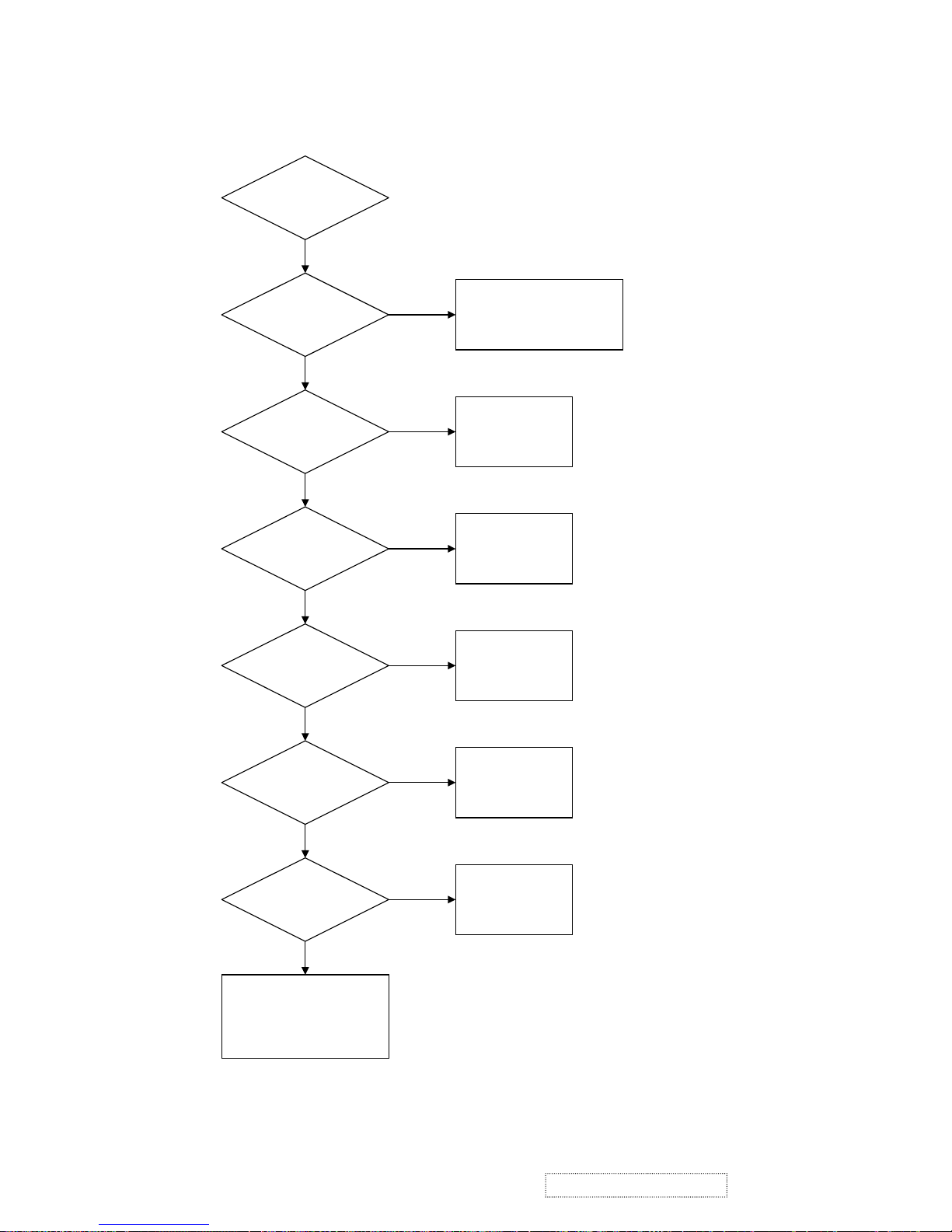
6. TROUBLE SHOOTING FLOW CHART
6.1. NO POWER
Start
5V
on
C101
I101
is
Failed?
5V
on
C314,C319
9.2V
on
C308
18V on F102
Check 3~4V
Q107,C315,I108
Check
D804,D807,
I801,I802,I803
D801,F801
Replace
I101
Check
Q101,I107,Q114
Check
L111,D203,
I108,Q106
Check
Q108,I109,F102
N
Y
Y
N
N
N
N
Y
Y
Y
-6V on
F103
Check
D201,D202,F103,
C302,Q105,I106
N
Y
!
!
ViewSonic Corporation
15
Confidential –DoNotCopy
VE155s, VE500-2
VE155/b, VA520-2
Page 19
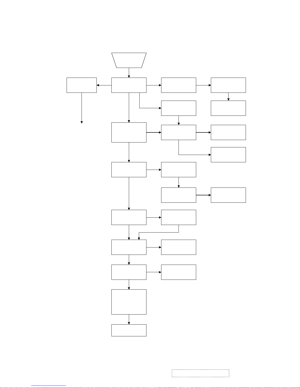
6.2. NO DISPLAY
No
Display
Check LED Color
Check Power
region
Refer to NO POWER
trouble shoot flow chart
Check IO cable is
connect OK ?
AmberDark
Check I/P signal is in
pwr saving state?
Yes
Check X100 Crystal
12MHz is working?
Amber & Green
Check I002 is OK ?
Press Power key
ON/OFF is OK ?
(See LED is green or
dark.)
Check uP I105
Reset is Ok ?
No
Change
I105
Yes
Check Reset circuit
Q113,D113
No
Yes
Press "1" key if OSD
menu is on display ?
Yes
Check Keypad
pcb is OK ?
No
Check if
Inverter is Ok ?
Yes
Change
Inverter
No
Check I001 MVZ if
RST Pin#155 have
reset pulse ?
Check uP I105
pin#24 send reset ?
pulse ?
No
Yes
Check X101 Crystal
12MHz is working ?
Change X101
No
Yes
Yes
Check J105,J106
data bus have signal
Change I001 LCD
controller IC
No
Yes
Check panel Powers
VDDD=3.3V
VDDA=9.2V
VDDG=18V
VEEG=-6V
Yes
Change LCD panel
Yes
No
Green
!
!
ViewSonic Corporation
16
Confidential –DoNotCopy
VE155s, VE500-2
VE155/b, VA520-2
Page 20
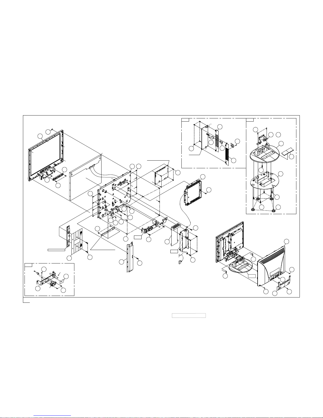
29
33
X2
30
34
35
30
30
33
X2
42
41
36
31
X2
39
38
X4
37 X4
43
40
KEYPAD PCB ASS'Y
26
8
27
X2
INVERTER PCB
U901
17
26
18
17
23
7
X4
V901
X79
X4
7
10 X4
MAIN PCB ASS'Y
24
14
X2
3
X25
4
6
1,2
15
20
X2
P983
16
45
13
X4
12
11
19
21
P984
X2
22
I/O CABLE
44
POWER PCB
X449
46
47
44
48
FIG.1
FIG.2
FIG.1
FIG.2
25
28
FIG.3
FIG.3
32
or
7. Exploded Diagram
!
!
ViewSonic Corporation
17
Confidential –DoNotCopy
VE155s, VE500-2
VE155/b, VA520-2
(6201-7956905701)
Page 21
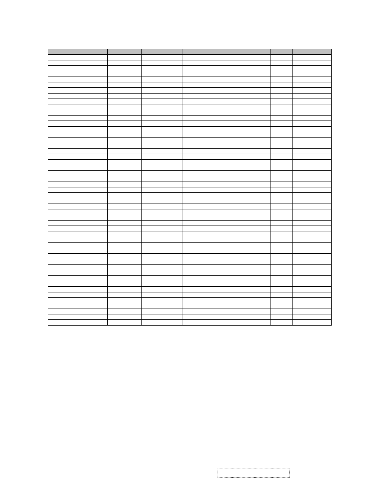
VE155S/VE500-2
Item ViewSonic P/N Ref. P/N. Description Specification Location Q'tyRemar
k
1 C-FP-0301-0376 2024262106 FRONT BEZEL VE155S/ABS+PC SILVER 1F01 1 VE155S
2 2024262107
FRONT BEZEL VE500-2/ABS+PC SILVER 1F01 1 VE500-2
3 M-MS-0808-8180 2053751901 LED INDIC.-PWR VE150-2/PMMA 94HB 1F02 1
4 PL-FK-0709-0128 2044260902 FUNCTION KEY VA520-2/ABS 94V0 SILVER 1F03 1
5 M-SCW-0824-0285 2084730082 SCREW,BND T+ M3X8(BND T+) 1F04 2
6 M-MS-0808-4026 2051350200 NAME PLATE JD144V3 VIEWSONIC 3BIRDS AL 1F05 1
7 2080002200 SCREW,SPE L355 M3x6 DH NICKEL-PLATED 1F09 8
8 2071964100 METAL FITTG VE155/CPT MRT14 SECC T=0.8 1F10 1
9 M-SCW-0824-0285 2084730082 SCREW,BND T+ M3X8(BND T+) 1F11 7
10 M-SCW-0824-0437 2082730062 SCREW,BND+ M3X6(BND+) 1F12 4
11 2071664200 SHIELD PLATE JT166L14/SPTE 0.3t MAIN BOARD 1F13 1
12 2082630062 SCREW M3X6 P=0.5 1F14 1
13 2081430062 SCREW,(WASH) M3X6 P=0.5(TOOTH WASHER) 1F15 4
14 2082630062 SCREW M3X6 P=0.5 1F16 2
15 2071659501 SHIELD PLATE SPTE t=0.3mm 1F17 1
16 2082630062 SCREW M3X6 P=0.5 1F18 1
17 M-SCW-0824-0285 2084730082 SCREW,BND T+ M3X8(BND T+) 1F19 2
18 2084740082 SCREW,BND T+ M4X8(BND T+) 1F20 1
19 2071960200 METAL FITTG L355 SECC t=0.8 1F21 1
20 2081430082 SCREW,(WASH) M3X8 P=0.5(TOOTH,WASHER) 1F22 2
21 2080002300 SCREW,SPE L355 M3*8 DH NICKEL-PLATED 1F23 2
22 M-SCW-0824-0493 2085740082 SCREW,B OTW+ SCREW B OTW+ M4X8 1F24 1
23 M-SCW-0824-0261 2084730142 SCREW,BND T+ M3X14(BND T+) 1F25 1
24 M-MS-0808-5476 2072450100 INSULATOR JT166E PC 185LX25.3WX14.6HX.2t 1F26 1
25 2081430062 SCREW,(WASH) M3X6 P=0.5(TOOTH WASHER) 1F27 1
26 M-SCW-0824-0123 2084740102 SCREW,BND T+ M4X10(BND T+) 1F29 2
27 M-SCW-0824-0437 2082730062 SCREW,BND+ M3X6(BND+) 1F30 2
28 2063451102 ADHESI SHEET 27.2x42.4 PVC COLOR:BLACK 1F31 1
29 C-BC-0302-0388 2022258804 CABI BACK PC+ABS 94V0 BLACK 4001+SILVER 2C01 1
30 2084740104 SCREW,BND T+ M4X10(BND T+) (BLK) 2C02 3
31 2106652901 HINGE VE155 0'~90' 2C20 1
32 2106652902 HINGE VE155/0'~90' (2nd source for item 31 ) 2C20 1
33 M-SCW-0824-0493 2085740082 SCREW,B OTW+ SCREW B OTW+ M4X8 2C21 4
34 M-CV-0830-2466 2027255103 DUST COVER VA520-2/ASB 94HB BLACK 4001 2C24 1
35 2084730084 SCREW,BND T+ M3X8(BND T+) (BLK) 2C25 1
36 PL-PS-0715-0188 2028254603 STAND VA520-2/ABS 94HB BLACK 4001 5B01 1
37 PL-PD-0714-0069 2039802303 FOOT PAD VA520 CR420xφ16.5x5.8 BLACK 5B02 4
38 M-SCW-0824-0123 2084740102 SCREW,BND T+ M4X10(BND T+) 5B03 4
39 M-CV-0830-2465 2027255003 DUST COVER VA520(2)/ABS 94HB BLACK 4001 5B04 1
40 2071960702 METAL FITTG VE155 STAND SECC t=2mm 5B06 1
41 M-SCW-0824-0285 2084730082 SCREW,BND T+ M3X8(BND T+) 5B07 1
42 2087340126 SCREW,B SPW+ 4X12(+)SWRM-3 ZMC2-C 5B08 2
43 2080002400 SCREW,SPE VE155/3x8 STAND 5B09 1
44 2072258100 HEAT SINK AL-6063S t=1.5mm 9H01 2
45 2072452900 INSULATOR VE155/MYLAR t=0.2 PC ABS 94V0 9R02 1
46 2429150100 TUBE,SILICON JT156D2 TO-220ST 0.4mm 9R81 1
47 2105250700 SPRING PLATE SUS 301 9S01 1
48 M-SCW-0824-0285 2084730082 SCREW,BND T+ M3X8(BND T+) 9S02 1
49 M-SCW-0824-0285 2084730082 SCREW,BND T+ M3X8(BND T+) 9S03 4
8. Exploded Parts List
!
!
ViewSonic Corporation
18
Confidential –DoNotCopy
VE155s, VE500-2
VE155/b, VA520-2
Page 22

Item ViewSonic P/N Ref. P/N Description Specification Location Q'TY Remark
1 C-FP-0301-0931 2024262102
FRONT BEZEL VE150-2/ABS+PC GY7521 1F01
1
VE155
C-FP-0301-0842 2024262103
FRONT BEZEL VE155B/ABS+PC MIDNIGHT GRAY 1F01
1
VE155b
3 M-MS-0808-8922 2053751901
LED INDIC.-PWR VE150-2/PMMA 94HB 1F02
1
4 PL-FK0707-0137 2044260901
FUNCTION KEY VE150-2/ABS 94V0 GY7521 1F03
1
VE155
2044260904 FUNCTION KEY ABS 94V0 MIDNIGHT GRAY 1F03 1 VE155b
5 M-SCW-0824-0285 2084730082
SCREW,BND T+ M3X8(BND T+) 1F04
2
6 M-MS-0808-4026 2051350200
NAME PLATE JD144V3 VIEWSONIC 3BIRDS AL 1F05
1
7 M-SCW-0824-6715 2080002200
SCREW,SPE L355 M3x6 DH NICKEL-PLATED 1F09
8
8 M-BK-0805-0013 2071964100
METAL FITTG VE155/CPT MRT14 SECC T=0.8 1F10
1
9 M-SCW-0824-0285 2084730082
SCREW,BND T+ M3X8(BND T+) 1F11
7
10 M-SCW-0824-0437 2082730062
SCREW,BND+ M3X6(BND+) 1F12
4
11 M-MS-0808-8915 2071664200
SHIELD PLATE JT166L14/SPTE 0.3t MAIN BOARD 1F13
1
12 M-SCW-0824-6719 2082630062
SCREW M3X6 P=0.5 1F14
1
13 M-SCW-0824-6717 2081430062
SCREW,(WASH) M3X6 P=0.5(TOOTH WASHER) 1F15
4
14 M-SCW-0824-6719 2082630062
SCREW M3X6 P=0.5 1F16
2
15 M-MS-0808-8916 2071659501
SHIELD PLATE SPTE t=0.3mm 1F17
1
16 M-SCW-0824-6719 2082630062
SCREW M3X6 P=0.5 1F18
1
17 M-SCW-0824-0285 2084730082
SCREW,BND T+ M3X8(BND T+) 1F19
2
18 M-SCW-0824-6721 2084740082
SCREW,BND T+ M4X8(BND T+) 1F20
1
19 M-BK-0805-0014 2071960200
METAL FITTG L355 SECC t=0.8 1F21
1
20 M-SCW-0824-6718 2081430082
SCREW,(WASH) M3X8 P=0.5(TOOTH,WASHER) 1F22
2
21 M-SCW-0824-6744 2080002300
SCREW,SPE L355 M3*8 DH NICKEL-PLATED 1F23
2
22 M-SCW-0824-0493 2085740082
SCREW,B OTW+ SCREW B OTW+ M4X8 1F24
1
23 M-SCW-0824-0261 2084730142
SCREW,BND T+ M3X14(BND T+) 1F25
1
24 M-MS-0808-5476 2072450100
INSULATOR JT166E PC 185LX25.3WX14.6HX.2t 1F26
1
25 M-SCW-0824-6717 2081430062
SCREW,(WASH) M3X6 P=0.5(TOOTH WASHER) 1F27
1
26 M-SCW-0824-0123 2084740102
SCREW,BND T+ M4X10(BND T+) 1F29
2
27 M-SCW-0824-0437 2082730062
SCREW,BND+ M3X6(BND+) 1F30
2
28 M-MS-0808-8921 2063451104
ADHESI SHEET 27.2X42.4 PVC 0.5t GY7521 1F31
1
VE155
2063451102 ADHESI SHEET 27.2x42.4 PVC COLOR:BLACK 1F31 1 VE155b
29 C-BC-0302-0452 2022258802
CABI BACK VE155/ABS+PC GY7521 2C01
1
VE155
C-BC-0302-0387 2022258805
CABI BACK PC+ABS 94V0 MIDNIGHT GRAY 2C01
1
VE155b
30 M-SCW-0824-0123 2084740102
SCREW,BND T+ M4X10(BND T+) 2C02
3
VE155
2084740104 SCREW,BND T+ M4X10(BND T+) (BLK) 2C02
3
VE155b
31 M-MS-0808-0022 2106652901
HINGE VE155 0'~90' 2C20
1
32 M-MS-0808-0024 2106652902
HINGE VE155/0'~90' (2nd source for item 31) 2C20
1
33 M-SCW-0824-0493 2085740082
SCREW,B OTW+ SCREW B OTW+ M4X8 2C21
4
34 M-MS-0808-8922 2027255101
DUST COVER VE155/BACK ABS 94HB GY7521 2C24
1
VE155
M-MS-0808-8923 2027255102
DUST COVER ABS 94HB MIDNIGHT GRAY 2C24
1
VE155b
35 M-SCW-0824-0285 2084730082
SCREW,BND T+ M3X8(BND T+) 2C25
1
36 PL-PS-0715-0202 2028254601
STAND VE150-2/ABS 94HB GY7521 5B01
1
VE155
PL-PS-0715-0203 2028254602
STAND ABS 94HB MIDNIGHT GRAY 5B01
1
VE155b
37 PL-PD-0714-0058 2039802301
FOOT PAD CR 420x φ 16.5x5.8 5B02
4
38 M-SCW-0824-6745 2084740104
SCREW,BND T+ M4X10(BND T+) (BLK) 5B03
4
39 M-MS-0808-8924 2027255001
DUST COVER VE155/ABS 94HB GY7521 5B04
1
VE155
M-CV-0830-0022 2027255002
DUST COVER ABS 94HB MIDNIGHT GRAY 5B04
1
VE155b
40 M-BK-0805-0015 2071960702
METAL FITTG VE155 STAND SECC t=2mm 5B06
1
41 M-SCW-0824-0285 2084730082
SCREW,BND T+ M3X8(BND T+) 5B07
1
42 M-SCW-0824-6746 2087340126
SCREW,B SPW+ 4X12(+)SWRM-3 ZMC2-C 5B08
2
43 M-SCW-0824-6716 2080002400
SCREW,SPE VE155/3x8 STAND 5B09
1
44 M-MS-0808-8917 2072258100
HEAT SINK AL-6063S t=1.5mm 9H01
2
45 M-MS-0808-8918 2072452900
INSULATOR VE155/MYLAR t=0.2 PC ABS 94V0 9R02
1
46 M-MS-0808-8919 2429150100
TUBE,SILICON JT156D2 TO-220ST 0.4mm 9R81
1
47 M-MS-0808-8920 2105250700
SPRING PLATE SUS 301 9S01
1
48 M-SCW-0824-0285 2084730082
SCREW,BND T+ M3X8(BND T+) 9S02
1
49 M-SCW-0824-0285 2084730082
SCREW,BND T+ M3X8(BND T+) 9S03
4
VE155/VE155b
!
!
ViewSonic Corporation
19
Confidential –DoNotCopy
VE155s, VE500-2
VE155/b, VA520-2
PL-FK0709-0147
M-MS-0808-9096
M-SCW-0824-6792
Page 23

Item ViewSonic P/N Ref. P/N Location Q'TY
1 C-FP-0301-0104 2024262104
FRONT BEZEL VA520(2)ABS+PC SILVER 1F01
1
3 M-MS-0808-8180 2053751901
LED INDIC.-PWR VE150-2/PMMA 94HB 1F02
1
4 PL-FK-0709-0128 2044260902
FUNCTION KEY VA520-2/ABS 94V0 SILVER 1F03
1
5 M-SCW-0824-0285 2084730082
SCREW,BND T+ M3X8(BND T+) 1F04
2
6 M-MS-0808-4026 2051350200
NAME PLATE JD144V3 VIEWSONIC 3BIRDS AL 1F05
1
7 M-SCW-0824-6715 2080002200
SCREW,SPE L355 M3x6 DH NICKEL-PLATED 1F09
8
8
M-BK-0805-0013
2071964100
METAL FITTG VE155/CPT MRT14 SECC T=0.8 1F10
1
9 M-SCW-0824-0285 2084730082
SCREW,BND T+ M3X8(BND T+) 1F11
7
10 M-SCW-0824-0437 2082730062
SCREW,BND+ M3X6(BND+) 1F12
4
11
M-MS-0808-8915
2071664200
SHIELD PLATE JT166L14/SPTE 0.3t MAIN BOARD 1F13
1
12 M-SCW-0824-6719 2082630062
SCREW M3X6 P=0.5 1F14
1
13 M-SCW-0824-6717 2081430062
SCREW,(WASH) M3X6 P=0.5(TOOTH WASHER) 1F15
4
14 M-SCW-0824-6719 2082630062
SCREW M3X6 P=0.5 1F16
2
15
M-MS-0808-8916
2071659501
SHIELD PLATE SPTE t=0.3mm 1F17
1
16 M-SCW-0824-6719 2082630062
SCREW M3X6 P=0.5 1F18
1
17 M-SCW-0824-0285 2084730082
SCREW,BND T+ M3X8(BND T+) 1F19
2
18 M-SCW-0824-6721 2084740082
SCREW,BND T+ M4X8(BND T+) 1F20
1
19
M-BK-0805-0014
2071960200
METAL FITTG L355 SECC t=0.8 1F21
1
20 M-SCW-0824-6718 2081430082
SCREW,(WASH) M3X8 P=0.5(TOOTH,WASHER) 1F22
2
21
M-SCW-0824-6744
2080002300
SCREW,SPE L355 M3*8 DH NICKEL-PLATED 1F23
2
22 M-SCW-0824-0493 2085740082
SCREW,B OTW+ SCREW B OTW+ M4X8 1F24
1
23 M-SCW-0824-6747 2085730102
SCREW,B OTW+ M3x10 SCREW B OTW+ 1F25
1
24 M-MS-0808-5476 2072450100
INSULATOR JT166E PC 185LX25.3WX14.6HX.2t 1F26
1
25 M-SCW-0824-6717 2081430062
SCREW,(WASH) M3X6 P=0.5(TOOTH WASHER) 1F27
1
26 M-SCW-0824-0123 2084740102
SCREW,BND T+ M4X10(BND T+) 1F29
2
27 M-SCW-0824-0437 2082730062
SCREW,BND+ M3X6(BND+) 1F30
2
28 M-MS-0808-1664 2063451102
ADHESI SHEET 27.2x42.4 PVC COLOR:BLAC
K
1F31
1
29 C-BC-0302-0388 2022258804
CABI BAC
K
PC+ABS 94V0 BLACK 4001+SILVER 2C01
1
30
M-SCW-0824-6745
2084740104
SCREW,BND T+ M4X10
(
BND T+) (BLK
)
2C02
3
31 M-MS-0808-0022 2106652901
HINGE VE155 0'~90' 2C20
1
32 M-MS-0808-0024 2106652902
HINGE VE155/0'~90' (2nd source for item 31) 2C20
1
33 M-SCW-0824-0493 2085740082
SCREW,B OTW+ SCREW B OTW+ M4X8 2C21
4
34 M-CV-0830-2466 2027255103
DUST COVER VA520-2/ASB 94HB BLACK 4001 2C24
1
35 M-SCW-0824-0416 2084730084
SCREW,BND T+ M3X8
(
BND T+) (BLK
)
2C25
1
36 PL-PS-0715-0188 2028254603
STAND VA520-2/ABS 94HB BLACK 4001 5B01
1
37 PL-PD-0714-0069 2039802303
FOOT PAD VA520 CR420x
φ
16.5x5.8 BLAC
K
5B02
4
38 M-SCW-0824-0123 2084740102
SCREW,BND T+ M4X10
(
BND T+
)
5B03
4
39 M-CV-0830-2465 2027255003
DUST COVER VA520
(2)
/ABS 94HB BLACK 4001 5B04
1
40
M-BK-0805-0015
2071960702
METAL FITTG VE155 STAND SECC t=2m
m
5B06
1
41 M-SCW-0824-0285 2084730082
SCREW,BND T+ M3X8
(
BND T+
)
5B07
1
42
M-SCW-0824-6746
2087340126
SCREW,B SPW+ 4X12
(+)
SWRM-3 ZMC2-C 5B08
2
43 M-SCW-0824-6716 2080002400
SCREW,SPE VE155/3x8 STAND 5B09
1
44
M-MS-0808-8917
2072258100
HEAT SIN
K
AL-6063S t=1.5m
m
9H01
2
45
M-MS-0808-8918
2072452900
INSULATOR VE155/MYLAR t=0.2 PC ABS 94V0 9R02
1
46
M-MS-0808-8919
2429150100
TUBE,SILICON JT156D2 TO-220ST 0.4mm 9R81
1
47
M-MS-0808-8920
2105250700
SPRING PLATE SUS 301 9S01
1
48 M-SCW-0824-0285 2084730082
SCREW,BND T+ M3X8
(
BND T+
)
9S02
1
49 M-SCW-0824-0285 2084730082
SCREW,BND T+ M3X8
(
BND T+
)
9S03
4
VA520-2
Description
!
!
ViewSonic Corporation
20
Confidential –DoNotCopy
VE155s, VE500-2
VE155/b, VA520-2
Specification
Page 24
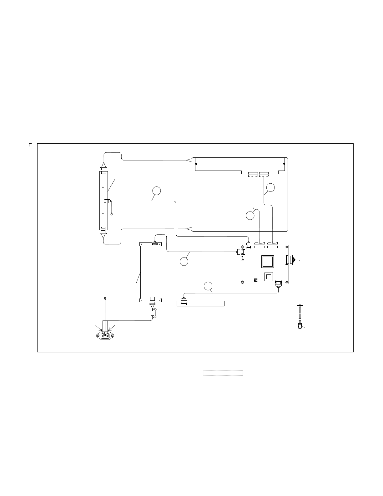
KEYPAD PCB
POWER PCB
TO:METAL FITTG
GND
(BLU)(BRN)
P801
P701
2202120100 V:0.02
P802
P982
JP2
JP1
JP3
P802
TO:GND
P983
INVERTER PCB
P981
P980
LCD PANEL
AC SOCKET ASS'Y
N
(BLU) (BRN)
L
J109
1
3
I001
J107
MAIN PCB
5
I105
J108
J110
5
1
1
5
1
J106
50
1
J103
1
8
1
J105
50
1
13
J101
I/O CABLE
P961
!
!
ViewSonic Corporation
21
Confidential –DoNotCopy
VE155s, VE500-2
VE155/b, VA520-2
Page 25

SWITCHING POWER SUPPLY
5V for system
AC 110~220V
INPUT
12V for INVERTER
R
G
B
Hsync
Vsync
BUF
I101
74LCV14
PA-HSYNC
PA-VSYNC
I102
24LC21
EEPROM DDC
SDA/SCL
FROM
D-SUB
15 PIN
I105
8051PLCC
OSC.
12MHZ
X100
KEYPAD
LCD FLAT PANEL
48 Bits
I2C BUS
INVERTER
TO
BACKLIGHT
High Volt
CPH1
STH1,LP,INV1,INV2
POL,STV1,CPV
MRT
MASCOT VZ
I001
LCD CONTROLLER
ADC+ SCALAR + T-CON
DC-DC
for PANEL POWER
VCOM 3.6V
VDDG 18V
VEEG -6V
VDDA 9.2V
VDDD 3.3V
BLT_ON
DC_EN
AUDIO AMP.
I601
TDA7053A/TDA7057
VOLUMN CONTROL
AUDIO
IN
BRIGHTNESS
I100
24LC16B
EEPROM
OPTION
EDID I2C BUS
15 inch LCD MONITOR BLOCK DIAGRAM
OSC.
12MHZ
X101
I108 AIC1341
Q105,Q106,Q107
Q108,Q114,Q115
I103,I104,I110
5V to 3.3V
3.3V to 2.5V
3.3V 2.5V
SPEAKER
9. Block Diagram
!
!
ViewSonic Corporation
22
Confidential –DoNotCopy
VE155s, VE500-2
VE155/b, VA520-2
Page 26

Optional
Optional
74LVC14 VCC IS +3.3V
D12 NF4 C14 R11 I2
ORANGEGREEN
R108 change to C172
*JT166S14 for Great-Wall
D701:Blue/Orange
Contral_key_pad
DDC-SDA
GREENGREEN
DDC-SCL
DDC-SDA
VSYNC
DDC_VCCA
VGA_GND
VGA-GND
PC_5V
BLUE
HSYNC VSYNC
DDC-SCL
RED
B-GND
G-GND
R-GND
VSYNC
HSYNC
RED
BLUE
PWR/LED
1
2
DOWN
PSM/LED
PWR/SW
UP
DDC-SCL DDC-SDA
PA-HSYNC 2
PA-VSYNC 2
PA-GREEN 2
SOGI 2
PA-RED 2
PA-BLUE 2
DDC-SCL1 3
DDC-SDA1 3
DDC-SCL 3
DDC-SDA 3
VGA-DET
+3.3V
VCC
+3.3V
+3.3V
VCC
D108
1N4148
D109
1N4148
D105
1N4148
L101 32
R105 22
D110
1N4148
C110
150pF
C108
10P
R105
10K/NC
L103 32
R110 150
L102 32
R103 100
C113
0.1u
R107 100
S703
S701
S704
S705
C172
NC
P701
8 HEADER 2mm
1234567
8
S702
D701
C101 0.1u
C102 0.1u
J101
CONN RCPT 13
1
2
3
4
5
6
7
8
9
10
11
12
13
1
2
3
4
5
6
7
8
9
10
11
12
13
C100 NC
C103 0.1u
I101C
74LVC14
5 6
I101B
74LVC14
3 4
R229 330
I101E
74LVC14
11 10
I101D
74LVC14
9 8
I101F
74LVC14
13 12
R106 1K/NC
C104
33p
C111
33p
C169
10P
C170
10P
D116
5V6
2 1
R228
10K
D114
5V6
2 1
D115
5V6
2 1
D106
5V6
2 1
D107
5V6
2 1
I102
24LC21
1
2
3
4 5
6
7
8
NC
NC
NC
VSS SDA
SCK
VCLK
VCC
D111
1N4148
D112
1N4148
C109
0.1u
I101A
74LVC14
1 2
R101
75
R100
75
R109 150
C107
NC
C106
NC
C105
NC
R102
75
C112
0.1u
D104
1N4148
D103
1N4148
R111 150
L100
200
R104 100
10. Schematic Diagrams
10.1. VGA INPUT
!
!
ViewSonic Corporation
23
Confidential –DoNotCopy
VE155s, VE500-2
VE155/b, VA520-2
Page 27

DA1 C45 R44 I3
TRACE> 30 MILS
GND
Vout
Vin
Vout
SOT-223
1
2
3
STH8
CPH2
OE2
OE3
Vref=2.5V
RA5
RA4
RA3
RA2
RA1
RA0
GA5
GA4
GA3
GA2
GA1
GA0
BA5
BA4
BA3
BA2
BA1
BA0
RB5
RB4
RB3
RB2
RB1
RB0
GB5
GB4
GB3
GB2
GB1
GB0
BB5
BB3
BB0
BB1
BB2
BB4
CPHA
RA7
RA6
GA7
GA6
BA7
BA6
BB7
BB6
GB6
GB7
RB7
RB6
CPH2
CPHA
INV1 4
SDA3
LP
4
BB[0..7] 4
STH1 4
STV1 4
RA[0..7] 4
IRQ-3
PA-VSYNC1
SCL3
PA-BLUE1
PA-RED1
INV2 4
SOGI1
POL 4
BLT_ON 3
CPV 4
PA-GREEN1
GA[0..7] 4
BA[0..7] 4
RB[0..7] 4
CPH1 4
PA-HSYNC1
GB[0..7] 4
PWM0 3
VDDCTRL 3
RESET_MASCOT3
PWM1 3
RESET3
3.3-PLL
3.3-ANA
PLL-VDD
+3.3V
+3.3V
VCC
3.3-ANA
PLL-VDD
3.3-PLL
VCC
+3.3V
+3.3V
+3.3V
GND
L107 200
L106 200
NC
R088
C148
22p
C147
22p
1MR144
X101 12MHZ
R080 3.3K
R116 10K
R142
0
R078 80
L105 200
C134
0.1u
R117 10K
I113
P2781
1
2
3
4 5
6
7
8
XIN/CLK
XOUT
FS1
LF VSS
MOD
FS0
VDD
C135 150p
50VNPO J
C090
680pf
C1365600p
50V X7R K
C163 0.1u
NC
R089
C114
22u / 16V
C116
22u / 16V
I103
AP1117 3.3V
1
23
GND
VOUTVIN
R113 22
R112 22/NC
R139 80
R091 1.2k
R120 4.7K
R135 22
R115 22
R124
10K
R123 22
NCR087
0
R090
NCR086
R084
0
R125 100
R085
NC
C115
220uF/ 16V
L104 200
R092
0
C126
10uF/50V
C121
10uF/50V
C117
10uF/50V
C132
0.1u
R119 22/NC
R118 22/NC
R134 0
TP2
I001
Mascot VZ
1
2
3
4
5
6
7
8
9
10
11
12
13
14
15
17
18
19
20
21
22
23
24
25
26
27
28
29
30
31
32
33
34
35
36
37
38
39
40
414243444546474849505152535455565758596061626364656667686970717273747576777879
80
120
119
118
117
116
115
114
113
112
111
110
109
108
107
106
105
104
103
102
101
100
99
98
97
96
95
94
93
92
91
90
89
88
87
86
85
84
83
82
81
160
159
158
157
156
155
154
153
152
151
150
149
148
147
146
145
144
143
142
141
140
139
138
137
136
135
134
133
132
131
130
129
128
127
126
125
124
123
122
121
16
DIBVDD
CAP_HREF
CAP_HSYNC
CAP_VSYNC
DIBVSS
BLU_INB_0
BLU_INB_1
BLU_INB_2
BLU_INB_3
BLU_INB_4
BLU_INB_5
BLU_INB_6
BLU_INB_7
DCVDD
GRN_INB_0
GRN_INB_2
GRN_INB_3
GRN_INB_4
GRN_INB_5
GRN_INB_6
GRN_INB_7
DCVSS
RED_INB_0
RED_INB_1/UV1
RED_INB_2
RED_INB_3
RED_INB_4
RED_INB_5
RED_INB_6
RED_INB_7
DIBVDD
DVDD
DVSS
DTEST
DVCC
DGND
VGA_VSYNC
VGA_HSYNC
SOGI
AVCC
AGND
VREFCPCZ
VCCABBIGNDAB
BCLP
VTOP
VBOT
VCCAGGIGNDAG
GCLP
TOUTP
TOUTM
VCCARRIGNDAR
RCLP
PLLVDD
PLLVSS
DCVSS
GPIO2
GPIO1
GPIO0
STH1
STH8LPDCVDD
SHC
XTAL
XTALI
DIBVSS
RLS
POL
CPH1
INV1
DCVSS
DOBVSS
BLU_OUTB_7
BLU_OUTB_6
BLU_OUTB_5
BLU_OUTB_4
DOBVDD
BLU_OUTB_3
BLU_OUTB_2
BLU_OUTB_1
BLU_OUTB_0
DOBVSS
RED_OUTA_7
RED_OUTA_6
RED_OUTA_5
RED_OUTA_4
DCVDD
RED_OUTA_3
RED_OUTA_2
RED_OUTA_1
RED_OUTA_0
DCVSS
GRN_OUTA_7
GRN_OUTA_6
GRN_OUTA_5
GRN_OUTA_4
DOBVDD
GRN_OUTA_3
GRN_OUTA_2
GRN_OUTA_1
GRN_OUTA_0
DOBVSS
BLU_OUTA_7
BLU_OUTA_6
BLU_OUTA_5
BLU_OUTA_4
DOBVDD
BLU_OUTA_3
BLU_OUTA_2
BLU_OUTA_1
BLU_OUTA_0
TVCLK
IRQ#
SCS#
SDA
SCL
RST
STV3
STV1
DCVSS
CPV
OE3
OE2
OE1
CPH2
PWM0
PWM1
DCVDD
INV2
LCD_VDD
LCD_VBL
DCVSS
RED_OUTB_7
RED_OUTB_6
RED_OUTB_5
RED_OUTB_4
DOBVDD
RED_OUTB_3
RED_OUTB_2
RED_OUTB_1
RED_OUTB_0
DOBVSS
GRN_OUTB_7
GRN_OUTB_6
GRN_OUTB_5
GRN_OUTB_4
DOBVDD
GRN_OUTB_3
GRN_OUTB_2
GRN_OUTB_1
GRN_OUTB_0
GRN_INB_1
C123 0.1u
C131 0.1u
C127 0.1u
C125 0.1u
C128 0.1u
C124 0.1u
C120 0.1u
C130 0.1u
C129 0.1u
C122 0.1u
R141 80
R140 22/NCC137
0.01u
C143
4700p
C138
4700p
C142
0.01u
C141
4700p
R186
1K/NC
C091
6800pf
I110
TL431
2 3
1
C139
0.1u
+
C140
10uF/50V
R127 100
R126 NC
TP6
TP3
R128 100
R121 3.3K
R122 80
R137 75
R079
3.3K
C144
0.1u
C145
0.1u
R133 80
C146
0.1u
C133
NC
R143 22
C161
22P
C162 NC
R077 100
C118
22u / 16V
TP1
R114 10K
I104
AP1117 3.3V
1
23
GND
VOUTVIN
C119
22u / 16V
10.2. MVZ
!
!
ViewSonic Corporation
24
Confidential –DoNotCopy
VE155s, VE500-2
VE155/b, VA520-2
Page 28

2.0 mm
Audio_control_(NC)
BCE
Winbond ISP
FOR Winbond ISP
RESET
UP
SDA
TxD
RxD
SCL
SDA
POWER
P
DOWN
D
ENTER
E
MENU
M
U
SCL
MUTE
LED_GRN
LED_OR
LED_GRN
LED_OR
LED_GREEN
AMBER
Brightness
DC_EN1
DC_EN1
PWM1
GND
PWM1
TxD
RxD
SCL2
IRQ-2
SDA2
DDC-SCL1
DDC-SDA1
RESET_MASCOT 2
DDC-SCL1
1
DDC-SDA1 1
BLT_ON 2
DC_EN
5
PWM1 2
PWM0
2
VDDCTRL2
RESET
2
VDDCTRL2
VDDD
4
EN_18V
VGA-DET
1
VCC
VCC
VCC
VCC
VCC
VCC
12V
12V
5V
VCC
VCC
VCC
VCC
+3.3V
+3.3V
R187
4.7K
J108
5pin/2mm
1
2
3
4
5
1
2
3
4
5
L115 3.5X9X0.8/NC
R169 1K
R168
1K
Q109
MMBT3904
C160
10uF/50V
C167
0.1u/NC
+
C288
470uF/16V
+
C289
470uF 16V/NC
C149
0.1u
C153
0.1u
L114
NC
C157
0.1u
L109 3.5X9X0.8
R188
4.7K
C154
0.1u
C155
0.1u
C156
0.1u
R076
2.2K/NC
C168
0.1u/NC
R189
4.7K
Q110
MMBT3904
R156
150
R155
150
1
6
7 17
18
28
29
39
40
P105
PLCC-44 SOCKET
+
C164
1uF/50V
L113 3.5X9X0.8
+
C282
470uF/16V
C150 22p
X100
12MHZ
J104
MRT DEBUG I/O/NC
1
2
3
4
5
10
9
8
7
6
1
2
3
4
5
10
9
8
7
6
R150 NC
I112 AP1117 3.3V
1
23
GND
VOUTVIN
I105
W78E62BP-PLCC
35
21
20
10
14
15
16
17
2
3
4
5
6
7
8
9
43
42
41
40
39
38
37
36
24
25
26
27
28
29
30
31
19
18
32
33
13
11
4422
23341
12
EA/VP
X1
X2
RESET
INT0 / P3.2
INT1 / P3.3
T0 / P3.4
T1 / P3.5
P1.0 / T2
P1.1 / T2EX
P1.2
P1.3
P1.4
P1.5
P1.6
P1.7
AD0 / P0.0
AD1 / P0.1
AD2 / P0.2
AD3 / P0.3
AD4 / P0.4
AD5 / P0.5
AD6 / P0.6
AD7 / P0.7
A8 / P2.0
A9 / P2.1
A10 / P2.2
A11 / P2.3
A12 / P2.4
A13 / P2.5
A14 / P2.6
A15 / P2.7
P3.7/ RD
P3.6 / WR
PSEN
ALE
P3.1 / TXD
P3.0 / RXD
VCCVSS
P4.0
P4.1
INT3 / P4.2
INT2 / P4.3
C152
0.1u
R075 150
R074 150
C151 22p
R191
4.7K
C066
22u 16V/NC
R193 NCI100
24LC16B
1
2
3
4
5
6
7
8
A0
A1
A2
VSS
SDA
SCL
WP
VCC
D113
1N4148
1 2
C212
0.1u
Q101
MMBT3904/NC
Q111
MMBT3904
R171
3.3K
Q102
MMBT3906
1
3
2
R195
2.2K
C166
0.1u
Q113
MMBT3906
1
2 3
C165
0.1u
R194
100K
L108
200
R173
1K
R172
4.7K
C209
0.1u
R196
4.7K
R081
150
Q103
MMBT3904
+ C171
NC
R184
NC
R183
0
R190 4.7K
Q100
MMBT3906
1
3
2
R145
4.7K
R146
4.7K
R147NCR148
NC
R185
NC
R161
150
R160
150
R154 330
R197
4.7K
Q104
2SA1020
J109
3PIN 2mm/NC
1
2
3
1
2
3
R165
4.7K
J103
1
2
3
4
5
6
7
8
1
2
3
4
5
6
7
8
R198
4.7K
R163 330
R166
4.7K
R159
150
R153 10K
R162 10K
R157
150
R158
150
R082
150
R083
150
10.3. MCU
!
!
ViewSonic Corporation
25
Confidential –DoNotCopy
VE155s, VE500-2
VE155/b, VA520-2
Page 29

3.6V
3.3V
-6V
18V
5
GA0
GA1
GA2
GA3
GA4
GA5
GA6
GA7
RA0
RA1
RA2
RA3
RA4
RA5
RA6
RA7
BB0
BB1
BB2
BB3
BB4
BB5
BB6
BB7
GB6
GB4
GB5
GB0
GB7
GB3
GB2
GB1
RB7
RB4
RB0
RB5
RB3
RB2
RB6
RB1
T_BA2
T_BA3
T_BA4
T_BA5
T_BA6
T_BA7
CPH1
T_BB5
T_BB4
T_BB6
T_BB3
T_BB7
T_BB2
T_GB7
T_BB0
T_GB4
T_BB1
T_GB6
T_GB5
T_GB2
T_GB3
T_RB1
T_RB5
T_RB7
T_GB1
T_RB4
T_GB0
T_RB2
T_RB6
T_RB3
T_RB0
VCOM
VDDD
VDDG
VEEG
VDDA
T_GA0
T_GA1
T_GA2
T_GA3
T_GA4
T_GA5
T_GA6
T_GA7
T_RA0
T_RA2
T_RA1
T_BB2
T_BB3
T_BB5
T_BB4
T_BB7
T_BB1
T_BB6
T_BB0
T_GB2
T_GB3
T_GB5
T_GB4
T_GB7
T_GB1
T_GB6
T_GB0
T_RB2
T_RB3
T_RB5
T_RB4
T_RB7
T_RB1
T_RB6
T_RB0
T_RA3
T_RA5
T_RA7
T_RA4
T_RA6
T_BA4
T_RA7
T_RA1
T_BA6
T_RA6
T_BA3
T_BA0
T_GA6
T_BA2
T_GA7
T_GA4
T_BA7
T_RA0
T_RA5
T_GA0
T_RA4
T_RA3
T_GA1
T_RA2
T_BA5
T_GA3
T_BA1
T_GA5
T_GA2
T_BA0
BA4
BA6
BA5
BA1
BA7
BA2
BA3
BA0
T_BA1
BB[0..7]2
BA[0..7]2
GA[0..7]2
RA[0..7]2
GB[0..7]2
RB[0..7]2
VDDD3
STV12
CPV2
VEEG5
VDDG5
STH12
LP2
POL2
INV12
INV22
VDDA5
CPH12
VCOM
J105
CON50
1
2
3
4
5
6
7
8
9
10
11
12
13
14
15
16
17
18
19
20
21
22
23
24
25
26
27
28
29
30
31
32
33
34
35
36
37
38
39
40
41
42
43
44
45
46
47
48
49
50
J106
CON50
1
2
3
4
5
6
7
8
9
10
11
12
13
14
15
16
17
18
19
20
21
22
23
24
25
26
27
28
29
30
31
32
33
34
35
36
37
38
39
40
41
42
43
44
45
46
47
48
49
50
CP09
33PX4 16V
1
5
2
6
3
7
4
8
CP10
33PX4 16V
1
5
2
6
3
7
4
8
C283 0.1uF
C284
0.1uF
C285
0.1uF
C286
0.1uF
C287 0.1uF
+
C218 10uF/50V
CP11
33PX4 16V
1
5
2
6
3
7
4
8
CP12
33PX4 16V
1
5
2
6
3
7
4
8
CP05
33PX4 16V
1
5
2
6
3
7
4
8
CP06
33PX4 16V
1
5
2
6
3
7
4
8
L122 80
CP02
33PX4 16V
1
5
2
6
3
7
4
8
CP01
33PX4 16V
1
5
2
6
3
7
4
8
L123 80
CP03
33PX4 16V
1
5
2
6
3
7
4
8
CP04
33PX4 16V
1
5
2
6
3
7
4
8
+
C215
10uF/50V
+
C214
10uF/50V
+
C217
10uF/50V
+
C216
10uF/50V
CP07
33PX4 16V
1
5
2
6
3
7
4
8
CP08
33PX4 16V
1
5
2
6
3
7
4
8
L124 80
L125 80
L127 80
L126 80
L128 80
L129 80
L133 80
L135 80
L132 80
L134 80
L131 80
L130 80
L142 80
L139 80
L138 80
L136 80
L137 80
L141 80
L143 80
L140 80
L151 80
L148 80
L150 80
L147 80
L146 80
L144 80
L145 80
L149 80
L153 80
L157 80
L159 80
L156 80
L158 80
L155 80
L154 80
L152 80
L162 80
L160 80
L161 80
L165 80
L167 80
L164 80
L166 80
L163 80
L120 80
L121 80
10.4. OUTPUT CONNECTOR
!
!
ViewSonic Corporation
26
Confidential –DoNotCopy
VE155s, VE500-2
VE155/b, VA520-2
Page 30

-10.9V
-4.3V
26.2V
2.5V
7.6mA
VDDA
VDDG
20ms Delay
VCOM_3.6V
VDDG_18V
VEEG_-6V
VDDA_9.2V
VCOM 4
VDDG 4
VEEG 4
VDDA 4
DC_EN3
EN_18V
5V12V
R222
360/1206
F103
0.25A/0603
R227
0/0603
D204
NC
R225
100K/0603
C304
0.1uF
R226
10R/1206
R224
0/0603
R223
360/1206
D206
EP05Q04/SMD
D200
EP05Q04/SMD
+
C3091uF/50V
+
C317
1uF/50V
Q107
CEA3055L
+
C315
100uF/16V
D205
EP05Q04/SMD
+
C302
10uF/50V
+
C301
10uF/50V
F101
2A/24V/1206
+
C318
47uF/50V
+
C316
1uF/50V
C310
10nF/0603
C313
22pF/0603
F102
0.25A/0603
L111 33uH
+
C307
220uF/16V
R205
21K 1%/0603
R212
3K3 1%/0603
+
C308
100uF/16V
R211
12K/0603
C312
22nF/0603
R209
5K6/0603
R210
110/0603
R217
3.3K/0603
R215
1.47K 1% 0603
I108
AIC1341/SMD
1
2
3
4
5
6
7
8 9
10
11
12
13
14
15
16
Phase
Ugate
SD
VCC
SS
FB2
Vin2
Gate2GND
GATE3
FB3
COMP1
FB1
OCSET
Pgnd
Lgate
R20736K
R218
21K 1%/0603
R216
1.15K 1%/0603
I109
TL431A
R213
3.3K/0603
+
C314
10uF/50V
R219
3K3 1%/0603
Q106
CEA3055L
D201
EP05Q04/SMD
D202
EP05Q04/SMD
+
C305
NC
R201
4K32 1%/0603
R200
10K/0603
R214
1K VR 10%
+
C319
NC
I106
TL431A
J110
CONN SOCKET 5
1
2
3
4
5
1
2
3
4
5
R202
1K/0603
R206
10K/0603
+
C311
10uF/50V
D203
EC10Q04/SMD
Q105
2SA2907
+
C303
10uF/50V
Q108
MMBT2222A
C300
0.1uF
Q115
MMBT3904/SMD
Q114
2SA1020Y
C321
0.1uF
R221
10K/0603
10.5. PANEL POWER
!
!
ViewSonic Corporation
27
Confidential –DoNotCopy
VE155s, VE500-2
VE155/b, VA520-2
Page 31

FG
4
3
2
1
(2) AL-EL capacitor - temperture is 105'C , if not indicated.
(1) Resistor - power rating is 1/4W , if not indicated.
+5V
+12V
+5V
GND
GND
C813
1500uF/10V
D805
31DQ06FC
t
R840
10/3A
1 2
I803
TL431CLP
2 3
1
R805
47K/5W
12
C812
100uF/400V
12
C810
0.033UF/100V MEF
C820
100n/50V
D804
FCH20A10 20A100V
R809
15/0.5W
C822
2200PF/500V
1 2
R811
4K7K/1%
D803
UF4005
D802
UF4007
1 2
C806
0.022UF/400V
12
F801
2.5A/250V
C819
1000P/50V
T801
L=1.2mH
9
3
5
6
1
2
7
8
11
10
12
C814
1500uF/10V
R804
430K/3W
1 2
Q801
NC
C801
0.22uF/275V
C808
47uF/50V
12
C809
100n/50V
12
C823
4700pF/250Vac
1 2
C811
NA
1 2
R807
JUMPER
R812
2K43K/1%
C824
0.22uF/275V
R814
2K2/1%
L804
15UH
R815
120/1W
C816
NC
P802
S5B-XH-A 5P/P=2.5
1
2
3
4
5
C815
1500uF/10V
12
R817
1K
L802
Bead,T3.5x0.8x9
D806
15V
D807
6.2V
R806
3K48/1%
R810
20K 1%
R813
100
P801
Connector
1
2
R816
10/0.5w
L801
JUMPER
R841
470
L803
JUMPER
I802
TLP621
I801
KA5M0365R
1 3
4 2
GNDVcc
FB D
C802
4700PF
12
L805
154
8
R801
1M 1/2W
12
C803
4700PF
12
- +
D801
KBJ4J 4A 600V
1
2
3
4
C817
1000uF/10V
12
C807
68P/1KV
10.6. AC-DC POWER
!
!
ViewSonic Corporation
28
Confidential –DoNotCopy
VE155s, VE500-2
VE155/b, VA520-2
Page 32

11. PCB Layout Diagrams
11.1. MAIN PCB TOP VIEW
!
!
ViewSonic Corporation
29
Confidential –DoNotCopy
VE155s, VE500-2
VE155/b, VA520-2
Page 33

11.3. CON PCB TOP VIEW
!
!
ViewSonic Corporation
30
Confidential –DoNotCopy
11.4. CON PCB BOTTOM VIEW
VE155s, VE500-2
VE155/b, VA520-2
Page 34

11.5. POWER PCB TOP VIEW
!
!
ViewSonic Corporation
31
Confidential –DoNotCopy
VE155s, VE500-2
VE155/b, VA520-2
Page 35

11.6. POWER PCB BOTTOM VIEW
!
!
ViewSonic Corporation
32
Confidential –DoNotCopy
VE155s, VE500-2
VE155/b, VA520-2
Page 36

Item ViewSonic P/NRef. P/
N
Location Q't
y
1 P-BX-0601-0862 2011168009 VE155/VA520 PALLET BOX 6P10 1
2 P-BX-0601-0861 2011168010 CARTON BOX VE155S VLCDS23585-2W 030303 6P01 1
3 P-FM-0602-0722 2012163600 POLYFOAM 6P20 1
4 P-FM-0602-0723 2012163700 POLYFOAM 6P21 1
5 M-MS-0808-0027 2013150901 PE bag 6P60 1
6 C-BC-0302-0388 2022258804 Rear enclosure 2C01 1
7 PL-PS-0715-0188 2028254603 BASE 5B01 1
8 M-LB-0813-0528 2055103400 ID label 6P52 1
9 M-SCW-0824-041
6
2084730084 SCREW,BND T+ 2C25 1
10 E-FS-0410-0009 2213125207 FUSE F801 1
11 E-T-0408-0010 2374300200 XFORMER INVERTER T802 1
12 A-VIO-0118-0030 2427501151 I/O CABLE P961 1
13 A-CD-VE155S 2438501121 CD wizard 6P80 1
14 C-FP-0301-0930 2603307468 Front enclosure 1
15 B-MB-0201-0020 6201-7956906271 PCB ASS'Y BLOCK (MAIN) 1
16 B-CB-0206-0103 6202-7956906271 PCB ASS'Y BLOCK (CON) 1
17 B-PS-0204-0004 6204-7956906271 PCB ASS'Y BLOCK (POWER) 1
18 C-FP-0301-0376 2024262106 FRONT BEZEL VE155S/ABS+PC SILVER 1F01 1
19 PL-FK-0709-0128 2044260902 FUNCTION KEY VA520-2/ABS 94V0 SILVER 1F03 1
20 M-LB-0813-0002 2056603050 SERIAL LABEL VIEWSONIC LCD SERIAL LABEL 6P54 1
21 M-MS-0808-4026 2051350200 NAME PLATE JD144V3 VIEWSONIC 3BIRDS AL 1
22 C-BC-0302-0388 2022258804 CABI BACK PC+ABS 94V0 BLACK 4001+SILVER 2C01 1
23 M-CV-0830-2466 2027255103 DUST COVER VA520-2/ASB 94HB BLACK 4001 2C24 1
24 M-LB-0813-0873 2055636017 LABEL VE155S VLCDS23585-2W 6P05 1
25 M-LB-0813-0874 2055131719 LABEL VE155S VLCDS23585-2W VER-17 6P50 1
26 M-MS-0808-0022 2106652901 HINGE VE155 0'~90' 1
27 M-MS-0808-0024 2106652902 HINGE VE155/0'~90' 1
28 PL-PS-0715-0188 2028254603 STAND VA520-2/ABS 94HB BLACK 4001 5B01 1
29 PL-PD-0714-0069 2039802303 FOOT PAD VA520 CR420xφ16.5x5.8 BLACK 1
30 M-CV-0830-2465 2027255003 DUST COVER VA520(2)/ABS 94HB BLACK 4001 5B04 1
31 M-LB-0813-0769 2055613293 LABEL VIEWSONIC OPEN STAND LABEL-LCD 1
32 A-CD-VE155S 2438501121 CD-OWNER GUIDE VE155S VER-17 WIZARD 6P80 1
33 M-MS-0808-8925 2002310349 GUARANT CARD VIEWSONIC VE155S QSG VER-17 6P84 1
34 M-MS-0808-0027 2013150901 POLYETHY BAG 700LX600WX0.03tmm PE-LD ADD>PE 1
35 M-LB-0813-0875 2055632026 LABEL VE155S VLCDS23585-2W 6P02 1
36 M-LB-0813-0876 2055613281 LABEL VIEWSONIC VA520 NUMBER STICKER 1
37 M-LB-0813-0858 2055613379 LABEL ViewSonic CONTAINER LABEL 1
38 M-LB-0813-0002 2056603050 LABEL SERIAL LABEL,VIEWSONIC LCD SERIAL LABEL 1
39 M-LB-0813-0528 2055103400 LABEL LABEL,JK0936F WEN (Date barecode) 1
40 M-MS-0808-0027 2013150901 POLYETHY BAG,700LX600WX0.03tmm PE-LD ADD>PE 1
41 M-CV-0830-0192 2027250101 DUST COVER,PE 1
Item ViewSonic P/N Ref. P/N Location Q'ty
1 A-PC-0106-0121 2427130046 POWER CORD ( USA WALL 1.8M BLACK) P951 1
2 A-PC-0106-0138 2427130047 POWER CORD ( E WALL 1.8M BLACK ) P952 1
VSE-E
Description
VE155s
Descri
p
tion
12. RECOMMENDED SPARE PARTS LIST
!
!
ViewSonic Corporation
33
Confidential –DoNotCopy
VE155s, VE500-2
VE155/b, VA520-2
Item ViewSonic P/N Ref. P/N Description Location Q'TY
1 A-PC-0106-0138 2427130047 POWER CORD CHINA WALL 1.83M BLACK P952 1
2 M-MS-0808-0020 2013150901 PE bag 6P60 1
3 M-LB-0813-0861 2055613324 LABEL VIEWSONIC LCD-15 3C STICKER 6P06 1
4 M-MS-0808-0028 2002310338 GUARANT CARD VIEWSONIC CHINA WARRANTY CARD 6P07 1
5 M-LB-0813-0862 2056606025 SERIAL LABEL VS ON WARRANTY CARD SN STICKER 6P08 1
6 M-LB-0813-0863 2056606010 SERIAL LABEL VIEWSONIC BOX STICKER-G 6P12 1
7 M-LB-0813-0864 2056606009 SERIAL LABEL VIEWSONIC SERVICE STICKER-G 6P15 1
8 M-MS-0808-0033 2013051800 POLYETHY BAG JT166A14 500LX470WX490H t=0.08 6P70 1
VSCN-G
Page 37

Item ViewSonic P/N Ref. P/N Description Location Q'ty
1 P-BX-0601-0862 2011168009 VE155/VA520 PALLET BOX 6P10 1
2 P-BX-0601-0886 2011168014 CARTON BOX 6P01 1
3 P-FM-0602-0722 2012163600 POLYFOAM 6P20 1
4 P-FM-0602-0723 2012163700 POLYFOAM 6P21 1
6 C-BC-0302-0536 2022258801 Rear enclosure 2C01 1
7 PL-PS-0715-0202 2028254601 STAND 5B01 1
8 M-LB-0813-0528 2055103400 ID label 6P52 1
9 M-SCW-0824-0416 2084730084 SCREW,BND T+ 2C25 1
10 E-FS-0410-0009 2213125207 FUSE F801 1
11 E-T-0408-0010 2374300200 XFORMER INVERTER T802 1
12 A-VIO-0118-0033 2427501150 I/O CABLE P961 1
13 A-CD-VE155 2438501127 CD wizard 6P80 1
14 C-FP-0301-0843 2603307292 Front enclosure (Panel Assy) 1
15 B-MB-0201-0020 6201-7956906271 PCB ASS'Y BLOCK (MAIN) 1
16 B-CB-0206-0090 6202-7956906271 PCB ASS'Y BLOCK (CON) 1
17 B-PS-0204-0004 6204-7956906271 PCB ASS'Y BLOCK (POWER) 1
18 M-MS-0808-7712 2024262102 FRONT BEZEL VE150-2/ABS+PC GY7521 1F01 1
19 PL-FK-0707-0137 2044260901 FUNCTION KEY,VE150-2/ABS 94V0 GY7521 1F03 1
20 M-LB-0813-0002 2056603050 SERIAL LABEL,VIEWSONIC LCD SERIAL LABEL 6P54 1
21 M-MS-0808-4026 2051350200 NAME PLATE,JD144V3 VIEWSONIC 3BIRDS AL 1F05 1
22 C-BC-0302-0536 2022258801 CABI BACK,VE150-2/ABS 94V0 GY7521 2C01 1
23 M-MS-0808-8926 2027255101 DUST COVER,VE155/BACK ABS 94HB GY7521 2C24 1
24 M-LB-0813-0877 2055636006 LABEL,VE155 VLCDS23585-1W 6P05 1
25 M-LB-0813-0879 2055131728 LABEL,VE155 VLCDS23585-1W VER.17 6P50 1
26 M-MS-0808-0022 2106652901 HINGE,VE155 0'~90' 2C20 1
27 M-MS-0808-0024 2106652902 HINGE,VE155/0'~90' 2C20 1
28 PL-PS-0715-0202 2028254601 STAND,VE150-2/ABS 94HB GY7521 5B01 1
29 PL-PD-0714-0069 2039802303 FOOT PAD,VA520 CR420xφ16.5x5.8 BLACK 5B02 4
30 M-MS-0808-8927 2027255001 DUST COVER,VE155/ABS 94HB GY7521 5B04 1
31 M-LB-0813-0769 2055613293 LABEL,VIEWSONIC OPEN STAND LABEL-LCD 5B10 1
32 A-CD-VE155 2438501127 CD-OWNER GUIDE,VE155 WIZARD DATE: 6P80 1
33 M-MS-0808-8928 2002310355 GUARANT CARD,VIEWSONIC VE155 QSG VER.17 6P81 1
34 M-MS-0808-1316 2013222536 POLYETHY BAG,250mmx350mmxt0.3 ADD>PE-LD< 6P85 1
35 M-LB-0813-0878 2055632014 LABEL,VE155 VLCDS23585-1W 6P02 1
36 M-LB-0813-0856 2055613379 LABEL,ViewSonic CONTAINER LABEL 6P11 42
37 M-LB-0813-0002 2056603050 SERIAL LABEL,VIEWSONIC LCD SERIAL LABEL 6P51 1
38 M-LB-0813-0528 2055103400 LABEL,JK0936F WEN (Date barecode) 6P52 1
39 M-MS-0808-0020 2013150901 POLYETHY BAG,700LX600WX0.03tmm PE-LD ADD>PE 6P60 1
40 M-CV-0830-0192 2027250101 DUST COVER,PE 6P90 1
Item ViewSonic P/N Ref. P/N Description Location Q'ty
1 A-PC-0106-0123 2427130035 SVT 18/3 1.8M USA WALL KDS P951 1
2 A-PC-0106-0142 2427130055 E WALL 1.83M(71922) P952 1
VE155
!
!
ViewSonic Corporation
34
Confidential –DoNotCopy
VE155s, VE500-2
VE155/b, VA520-2
Item ViewSonic P/N Ref. P/N Description Location Q'ty
1 A-PC-0106-0143 2427130082 POWER CORD CHINA WALL 1.83M GE96750 P951 1
2 M-MS-0808-0020 2013150901 PE bag 6P60 1
3 M-LB-0813-0861 2055613324 LABEL VIEWSONIC LCD-15 3C STICKER 6P06 1
4 M-MS-0808-0028 2002310338 GUARANT CARD VIEWSONIC CHINA WARRANTY CARD 6P07 1
5 M-LB-0813-0862 2056606025 SERIAL LABEL VS ON WARRANTY CARD SN STICKER 6P08 1
6 M-LB-0813-0863 2056606010 SERIAL LABEL VIEWSONIC BOX STICKER-G 6P12 1
7 M-LB-0813-0864 2056606009 SERIAL LABEL VIEWSONIC SERVICE STICKER-G 6P15 1
8 M-MS-0808-0033 2013051800 POLYETHY BAG JT166A14 500LX470WX490H t=0.08 6P70 1
VSCN-G
VSA-M, VSI-P, VSE-E
Page 38

Item ViewSonic P/N Ref. P/N Location Q'ty
1 P-BX-0601-0862 2011168009 VE155/VA520 PALLET BOX 6P10 1
2 P-BX-0601-0707 2011168013 CARTON BOX 6P01 1
3 P-FM-0602-0722 2012163600 POLYFOAM 6P20 1
4 P-FM-0602-0723 2012163700 POLYFOAM 6P21 1
5 M-MS-0808-0027 2013150901 PE-Bag 6P60 1
6 C-BC-0302-0387 2022258805 Rear enclosure 2C01 1
7 PL-PS-0715-0203 2028254602 BASE 5B01 1
8 M-LB-0813-0528 2055103400 ID label 6P52 1
9 M-SCW-0824-0416 2084730084 SCREW,BND T+ 2C25 1
10 E-FS-0410-0009 2213125207 FUSE F801 1
11 E-T-0408-0010 2374300200 XFORMER INVERTER T802 1
12 A-VIO-0118-0030 2427501151 I/O CABLE P961 1
13 A-CD-VE155-B 2438501128 CD wizard 6P80 1
14 M-MS-0808-0021 2603307517 Front enclosure 1
15 B-MB-0201-0020 6201-7956906271 PCB ASS'Y BLOCK (MAIN) 1
16 B-CB-0206-0103 6202-7956906271 PCB ASS'Y BLOCK (CON) 1
17 B-PS-0204-0004 6204-7956906271 PCB ASS'Y BLOCK (POWER) 1
18 C-FP-0301-0842 2024262103 FRONT BEZEL VE155B/ABS+PC MIDNIGHT GRAY 1F01 1
19 PL-BT-0706-0147 2044260904 FUNCTION KEY ABS 94V0 MIDNIGHT GRAY 1F03 1
20 M-LB-0813-0002 2056603050 SERIAL LABEL VIEWSONIC LCD SERIAL LABEL 6P54 1
21 M-MS-0808-4026 2051350200 NAME PLATE JD144V3 VIEWSONIC 3BIRDS AL 1F05 1
22 C-BC-0302-0387 2022258805 CABI BACK PC+ABS 94V0 MIDNIGHT GRAY 2C01 1
23 M-CV-0830-0053 2027255102 DUST COVER ABS 94HB MIDNIGHT GRAY 2C24 1
24 M-LB-0813-0674 2055636010 LABEL VE155B VLCDS23585-3W 6P05 1
25 M-LB-0813-0344 2055131729 LABEL VE155B VLCDS23585-3W VER.17 6P50 1
26 M-MS-0808-0022 2106652901 HINGE VE155 0'~90' 2C20 RA 1
27 M-MS-0808-0024 2106652902 HINGE VE155/0'~90' 2C20 RB 1
28 PL-PS-0715-0203 2028254602 STAND ABS 94HB MIDNIGHT GRAY 5B01 1
29 PL-PD-0714-0069 2039802303 FOOT PAD VA520 CR420xφ16.5x5.8 BLACK 5B02 1
30 M-CV-0830-0022 2027255002 DUST COVER ABS 94HB MIDNIGHT GRAY 5B04 1
31 M-LB-0813-0769 2055613293 LABEL VIEWSONIC OPEN STAND LABEL-LCD 5B10 1
32 A-UG-0107-0450 2438501128 CD-OWNER GUIDE VE155B WIZARD DATE: 6P80 1
33 M-MS-0808-0025 2002310356 GUARANT CARD VIEWSONIC VE155B QSG VER.17 6P81 1
34 M-MS-0808-0027 2013150901 POLYETHY BAG 700LX600WX0.03tmm PE-LD ADD>PE 6P60 1
35 M-LB-0813-0515 2055632015 LABEL VE155B VLCDS23585-3W 6P02 1
36 M-LB-0813-0858 2055613379 LABEL ViewSonic CONTAINER LABEL 6P11 1
37 M-LB-0813-0002 2056603050 LABEL SERIAL LABEL,VIEWSONIC LCD SERIAL LABEL 6P51 1
38 M-LB-0813-0528 2055103400 LABEL LABEL,JK0936F WEN (Date barecode) 6P52 1
39 M-MS-0808-0027 2013150901 POLYETHY BAG,700LX600WX0.03tmm PE-LD ADD>PE 6P60 1
40 M-CV-0830-0192 2027250101 DUST COVER,PE 6P90 1
Item ViewSonic P/N Ref. P/N Location Q'ty
1 A-PC-0106-0277 2427130097 POWER CORD CHINA WALL 1.83M BLACK P951 1
2 M-MS-0808-0020 2013150901 PE bag 6P60 1
3 M-LB-0813-0861 2055613324 LABEL VIEWSONIC LCD-15 3C STICKER 6P06 1
4 M-MS-0808-0028 2002310338 GUARANT CARD VIEWSONIC CHINA WARRANTY CARD 6P07 1
5 M-LB-0813-0862 2056606025 SERIAL LABEL VS ON WARRANTY CARD SN STICKER 6P08 1
6 M-LB-0813-0863 2056606010 SERIAL LABEL VIEWSONIC BOX STICKER-G 6P12 1
7 M-LB-0813-0864 2056606009 SERIAL LABEL VIEWSONIC SERVICE STICKER-G 6P15 1
8 M-MS-0808-0033 2013051800 POLYETHY BAG JT166A14 500LX470WX490H t=0.08 6P70 1
Item ViewSonic P/N Ref. P/N Location Q'ty
1 A-PC-0106-0121 2427130046 POWER CORD ( USA WALL 1.8M BLACK) P951 1
2 A-PC-0106-0138 2427130047 POWER CORD E WALL 1.8M BLACK P952 1
Description
VE155b
Description
VSCN-G
VSE-E,VSI-P,VSA-M
Description
!
!
ViewSonic Corporation
35
Confidential –DoNotCopy
VE155s, VE500-2
VE155/b, VA520-2
Page 39

Item ViewSonic P/N Ref. P/N Location Q'ty
1 P-BX-0601-0862 2011168009 VE155/VA520 PALLET BOX 6P10 1
2 P-BX-0601-0863 2011168011 VE500-2 VLCDS23585-2W 030403 6P01 1
3 P-FM-0602-0722 2012163600 POLYFOAM 6P20 1
4 P-FM-0602-0723 2012163700 POLYFOAM 6P21 1
5 M-MS-0808-6740 2013150901 PE bag 6P60 1
6 C-BC-0302-0388 2022258804 Rear enclosure 2C01 1
7 PL-PS-0715-0188 2028254603 STAND 5B01 1
8 M-LB-0813-0528 2055103400 LABEL 6P52 1
9 M-SCW-0824-0580 2084730084 SCREW,BND T+ 2C25 1
10 E-FS-0410-0009 2213125207 FUSE F801 1
11 E-T-0408-0514 2374300200 XFORMER INVERTER T802 1
12 A-VIO-0118-0030 2427501151 I/O CABLE P961 1
13 A-CD-VE500 2438501122 CD wizard 6P80 1
14 C-FP-0301-0400 2603307473 Front enclosure 1
15 B-MB-0201-0511 6201-7956906271 PCB ASS'Y BLOCK (MAIN) 1
16 B-CB-0206-0090 6202-7956906271 PCB ASS'Y BLOCK (CON) 1
17 B-PS-0204-0025 6204-7956906271 PCB ASS'Y BLOCK (POWER) 1
18 C-FP-0301-0381 2024262107 FRONT BEZEL VE500-2/ABS+PC SILVER 1F01 1
19 PL-FK-0709-0128 2044260902 FUNCTION KEY VA520-2/ABS 94V0 SILVER 1F03 1
20 M-LB-0813-0503 2056603050 SERIAL LABEL VIEWSONIC LCD SERIAL LABEL 6P54 1
21 M-MS-0808-4026 2051350200 NAME PLATE JD144V3 VIEWSONIC 3BIRDS AL 1
22 C-BC-0302-0388 2022258804 CABI BACK PC+ABS 94V0 BLACK 4001+SILVER 2C01 1
23 M-CV-0830-2466 2027255103 DUST COVER VA520-2/ASB 94HB BLACK 4001 2C24 1
24 M-LB-0813-0852 2055636017 LABEL VE155S VLCDS23585-2W 6P05 1
25 M-LB-0813-0853 2055131720 LABEL VE500-2 VLCDS23585-2W VER-17 6P50 1
26 M-MS-0808-6741 2106652901 HINGE VE155 0'~90' 1
27 M-MS-0808-6742 2106652902 HINGE VE155/0'~90' 1
28 PL-PS-0715-0188 2028254603 STAND VA520-2/ABS 94HB BLACK 4001 5B01 1
29 PL-PD-0714-0069 2039802303 FOOT PAD VA520 CR420xφ16.5x5.8 BLACK 1
30 M-CV-0830-2465 2027255003 DUST COVER VA520(2)/ABS 94HB BLACK 4001 5B04 1
31 M-LB-0813-0769 2055613293 LABEL VIEWSONIC OPEN STAND LABEL-LCD 1
32 A-CD-VE500-2 2438501122 CD-OWNER GUIDE VE500-2 VER-17 WIZARD 6P80 1
33 M-MS-0808-6743 2002310350 GUARANT CARD VIEWSONIC VE500-2 QSG VER-17 6P84 1
34 M-MS-08086744 2013150901 POLYETHY BAG 700LX600WX0.03tmm PE-LD ADD>PE 1
35 M-LB-0813-0854 2055632027 LABEL VE500-2 VLCDS23585-2W 6P02 1
36 M-LB-0813-0855 2055613281 LABEL VIEWSONIC VA520 NUMBER STICKER 1
37 M-LB-0813-0856 2055613379 LABEL ViewSonic CONTAINER LABEL 1
38 M-LB-0813-0857 2056603050 LABEL SERIAL LABEL,VIEWSONIC LCD SERIAL LABEL 1
39 M-LB-0813-0528 2055103400 LABEL LABEL,JK0936F WEN (Date barecode) 1
40 M-MS-0808-6745 2013150901 POLYETHY BAG,700LX600WX0.03tmm PE-LD ADD>PE 1
41 M-CV-0830-0192 2027250101 DUST COVER,PE 1
VE500-2 VSA- M
Description
!
!
ViewSonic Corporation
36
Confidential –DoNotCopy
VE155s, VE500-2
VE155/b, VA520-2
Item ViewSonic P/N Ref. P/N Location Q'ty
1 A-PC-0106-0277 2427130097 POWER CORD CHINA WALL 1.83M BLACK P951 1
2 M-MS-0808-0020 2013150901 PE bag 6P60 1
3 M-LB-0813-0861 2055613324 LABEL VIEWSONIC LCD-15 3C STICKER 6P06 1
4 M-MS-0808-0028 2002310338 GUARANT CARD VIEWSONIC CHINA WARRANTY CARD 6P07 1
5 M-LB-0813-0862 2056606025 SERIAL LABEL VS ON WARRANTY CARD SN STICKER 6P08 1
6 M-LB-0813-0863 2056606010 SERIAL LABEL VIEWSONIC BOX STICKER-G 6P12 1
7 M-LB-0813-0864 2056606009 SERIAL LABEL VIEWSONIC SERVICE STICKER-G 6P15 1
8 M-MS-0808-0033 2013051800 POLYETHY BAG JT166A14 500LX470WX490H t=0.08 6P70 1
Item ViewSonic P/N Ref. P/N Location Q'ty
1 A-PC-0106-0121 2427130046 POWER CORD ( USA WALL 1.8M BLACK) P951 1
2 A-PC-0106-0138 2427130047 POWER CORD E WALL 1.8M BLACK P952 1
Description
VSCN-G
VSE-E,VSI-P,VSA-M
Description
Page 40

Item ViewSonic P/N Ref. P/N Locatio
n
Q't
y
1 P-BX-0601-0862 2011168009 VE155/VA520 PALLET BOX 6P10 1
2 P-BX-0601-0879 2011168012 CARTON BOX 6P01 1
3 P-FM-0602-0722 2012163600 POLYFOAM 6P20 1
4 P-FM-0602-0723 2012163700 POLYFOAM 6P21 1
5 M-MS-0808-0027 2013150901 PE bag 6P60 1
6 C-BC-0302-0388 2022258804 Rear enclosure 2C01 1
7 PL-PS-0715-0188 2028254603 STAND 5B01 1
8 M-LB-0813-0528 2055103400 ID label 6P52 1
9 M-SCW-0824-0416 2084730084 SCREW,BND T+ 2C25 1
10 E-FS-0410-0009 2213125207 FUSE F801 1
11 E-T-0408-0010 2374300200 XFORMER INVERTER T802 1
12 A-VIO-0118-0030 2427501151 I/O CABLE P961 1
13 A-CD-VA520-2 2438501120 CD wizard 6P80 1
14 C-FP-0301-0842 2603307306 Front enclosure 1
15 B-MB-0201-0020 6201-7956906271 PCB ASS'Y BLOCK (MAIN) 1
16 B-CB-0206-0103 6202-7956906271 PCB ASS'Y BLOCK (CON) 1
17 B-PS-0204-0004 6204-7956906271 PCB ASS'Y BLOCK (POWER) 1
18 C-FP-0301-0104 2024262104 FRONT BEZEL VA520(2)ABS+PC SILVER 1F01 1
19 PL-FK-0709-0128 2044260902 FUNCTION KEY VA520-2/ABS 94V0 SILVER 1F03 1
20 M-LB-0813-0002 2056603050 SERIAL LABEL VIEWSONIC LCD SERIAL LABEL 6P54 1
21 M-MS-0808-4026 2051350200 NAME PLATE JD144V3 VIEWSONIC 3BIRDS AL 1
22 C-BC-0302-0388 2022258804 CABI BACK PC+ABS 94V0 BLACK 4001+SILVER 2C01 1
23 M-CV-0830-2466 2027255103 DUST COVER VA520-2/ASB 94HB BLACK 4001 2C24 1
24 M-LB-0813-0866 2055636007 LABEL VA520 VLCDS23585-2W 6P05 1
25 M-LB-0813-0867 2055131718 LABEL VA520-2 VLCDS23585-2W VER-17 6P50 1
26 M-MS-0808-0022 2106652901 HINGE VE155 0'~90' 1
27 M-MS-0808-0024 2106652902 HINGE VE155/0'~90' 1
28 PL-PS-0715-0188 2028254603 STAND VA520-2/ABS 94HB BLACK 4001 5B01 1
29 PL-PD-0714-0069 2039802303 FOOT PAD VA520 CR420xφ16.5x5.8 BLACK 1
30 M-CV-0830-2465 2027255003 DUST COVER VA520(2)/ABS 94HB BLACK 4001 5B04 1
31 M-LB-0813-0769 2055613293 LABEL VIEWSONIC OPEN STAND LABEL-LCD 1
32 A-CD-VA520-2 2438501120 CD-OWNER GUIDE VA520-2 VER-17 WIZARD 6P80 1
33 M-MS-0808-0050 2002310348 GUARANT CARD VIEWSONIC-2 QSG VER-17 6P84 1
34 M-MS-0808-0027 2013150901 POLYETHY BAG 700LX600WX0.03tmm PE-LD ADD>PE 1
35 M-LB-0813-0868 2055632017 LABEL VA520 VLCDS23585-2W 1
36 M-LB-0813-0869 2055613281 LABEL VIEWSONIC VA520 NUMBER STICKER 1
37 M-LB-0813-0870 2055613379 LABEL ViewSonic CONTAINER LABEL 1
38 M-LB-0813-0002 2056603050 LABEL VIEWSONIC LCD SERIAL LABEL 1
39 M-LB-0813-0528 2055103400 LABEL LABEL,JK0936F WEN (Date barecode) 1
40 M-MS-0808-0027 2013150901 POLYETHY BAG,700LX600WX0.03tmm PE-LD ADD>PE 1
41 M-CV-0830-0192 2027250101 DUST COVER,PE 1
Item ViewSonic P/N Ref. P/N Description Location Q'ty
1 A-PC-0106-0277 2427130097 POWER CORD CHINA WALL 1.83M BLACK P951 1
2 M-MS-0808-0020 2013150901 PE bag 6P06 1
3 M-LB-0813-0861 2055613324 LABEL VIEWSONIC LCD-15 3C STICKE
R
6P06 1
4 M-MS-0808-0028 2002310338 GUARANT CARD VIEWSONIC CHINA WARRANTY CAR
D
6P07 1
5 M-LB-0813-086
2
2056606025 SERIAL LABEL VS ON WARRANTY CARD SN STICKE
R
6P08 1
6 M-LB-0813-086
3
2056606010 SERIAL LABEL VIEWSONIC BOX STICKER-
G
6P12 1
7 M-LB-0813-086
4
2056606009 SERIAL LABEL VIEWSONIC SERVICE STICKER-
G
6P15 1
8 M-MS-0808-0033 2013051800 POLYETHY BAG JT166A14 500LX470WX490H t=0.0
8
6P70 1
Item ViewSonic P/N Ref. P/N Description Location Q'ty
1 M-MS-0808-0515 2001950139 ATTACH SHEET VIEWSONIC LCD PROMOTION INSERT 6P83 1
Item ViewSonic P/N Ref. P/N Description Location Q'ty
1 A-PC-0106-0121 2427130046 POWER CORD ( USA WALL 1.8M BLACK
)
P951 1
2 A-PC-0106-013
8
2427130047 POWER CORD ( E WALL 1.8M BLACK
)
P952 1
V
SE-E ; VSI-P
V
A520-2
Description
V
SCN-G
V
SA-M
!
ViewSonic Corporation
37
Confidential –DoNotCopy
VE155s, VE500-2
VE155/b, VA520-2
Page 41

VE155s
ItemVIEWSONIC P/NRef.No.DESCRIPTIONSPECFICATIONLOC QTY
1 2700111700 SET ASS'Y VE155(S) B011 1
2 2701111700 PCB ASS'Y VE155(S) B021 1
3 2702111700 PCB-MAIN VE155(S) BA31 1
4 2704111700 AUTO INSERT-MAIN VE155(S) BA41 1
5 2706111700 SMT-MAIN VE155(S) BA51 1
6 2340733008 CAP,ARRAY P=0.8 85'C 1206Y5V 33.000PF 16V M 8P CP01 1
7 2340733008 CAP,ARRAY P=0.8 85'C 1206Y5V 33.000PF 16V M 8P CP02 1
8 2340733008 CAP,ARRAY P=0.8 85'C 1206Y5V 33.000PF 16V M 8P CP03 1
9 2340733008 CAP,ARRAY P=0.8 85'C 1206Y5V 33.000PF 16V M 8P CP04 1
10 2340733008 CAP,ARRAY P=0.8 85'C 1206Y5V 33.000PF 16V M 8P CP05 1
11 2340733008 CAP,ARRAY P=0.8 85'C 1206Y5V 33.000PF 16V M 8P CP06 1
12 2340733008 CAP,ARRAY P=0.8 85'C 1206Y5V 33.000PF 16V M 8P CP07 1
13 2340733008 CAP,ARRAY P=0.8 85'C 1206Y5V 33.000PF 16V M 8P CP08 1
14 2340733008 CAP,ARRAY P=0.8 85'C 1206Y5V 33.000PF 16V M 8P CP09 1
15 2340733008 CAP,ARRAY P=0.8 85'C 1206Y5V 33.000PF 16V M 8P CP10 1
16 2340733008 CAP,ARRAY P=0.8 85'C 1206Y5V 33.000PF 16V M 8P CP11 1
17 2340733008 CAP,ARRAY P=0.8 85'C 1206Y5V 33.000PF 16V M 8P CP12 1
18 2341168196 CAP,CHIP 125'C CS 0603/COG/50V 680p J T C090 1
19 2346168296 CAP,CHIP 125'C CS 0603/X7R/50V 6800p K T C091 1
20 E-C-0404-3815 2346410496 CAP,CHIP 85'C CS 0603/Y5V/50V 0.1u Z T C101 1
21 E-C-0404-3815 2346410496 CAP,CHIP 85'C CS 0603/Y5V/50V 0.1u Z T C102 1
22 E-C-0404-3815 2346410496 CAP,CHIP 85'C CS 0603/Y5V/50V 0.1u Z T C103 1
23 E-C-0404-3900 2341133096 CAP,CHIP 125'C CS 0603/COG/50V 33p J T C104 1
24 E-C-0404-3898 2341110096 CAP,CHIP 125'C CS 0603/COG/50V 10p J T C108 1
25 E-C-0404-3815 2346410496 CAP,CHIP 85'C CS 0603/Y5V/50V 0.1u Z T C109 1
26 2341115196 CAP,CHIP 125'C CS 0603/COG/50V 150p J T C110 1
27 E-C-0404-3900 2341133096 CAP,CHIP 125'C CS 0603/COG/50V 33p J T C111 1
28 E-C-0404-3815 2346410496 CAP,CHIP 85'C CS 0603/Y5V/50V 0.1u Z T C112 1
29 E-C-0404-3815 2346410496 CAP,CHIP 85'C CS 0603/Y5V/50V 0.1u Z T C113 1
30 E-C-0404-3815 2346410496 CAP,CHIP 85'C CS 0603/Y5V/50V 0.1u Z T C120 1
31 E-C-0404-3815 2346410496 CAP,CHIP 85'C CS 0603/Y5V/50V 0.1u Z T C122 1
32 E-C-0404-3815 2346410496 CAP,CHIP 85'C CS 0603/Y5V/50V 0.1u Z T C123 1
33 E-C-0404-3815 2346410496 CAP,CHIP 85'C CS 0603/Y5V/50V 0.1u Z T C124 1
34 E-C-0404-3815 2346410496 CAP,CHIP 85'C CS 0603/Y5V/50V 0.1u Z T C125 1
35 E-C-0404-3815 2346410496 CAP,CHIP 85'C CS 0603/Y5V/50V 0.1u Z T C127 1
36 E-C-0404-3815 2346410496 CAP,CHIP 85'C CS 0603/Y5V/50V 0.1u Z T C128 1
37 E-C-0404-3815 2346410496 CAP,CHIP 85'C CS 0603/Y5V/50V 0.1u Z T C129 1
38 E-C-0404-3815 2346410496 CAP,CHIP 85'C CS 0603/Y5V/50V 0.1u Z T C130 1
39 E-C-0404-3815 2346410496 CAP,CHIP 85'C CS 0603/Y5V/50V 0.1u Z T C131 1
40 E-C-0404-3815 2346410496 CAP,CHIP 85'C CS 0603/Y5V/50V 0.1u Z T C132 1
41 E-C-0404-3815 2346410496 CAP,CHIP 85'C CS 0603/Y5V/50V 0.1u Z T C134 1
42 2341115196 CAP,CHIP 125'C CS 0603/COG/50V 150p J T C135 1
43 2346156296 CAP,CHIP 125'C CS 0603/X7R/50V 5600p K T C136 1
44 E-C-0404-4424 2346110396 CAP,CHIP 125'C CS 0603/X7R/50V 0.01u K T C137 1
45 2346147296 CAP,CHIP 125'C CS 0603/X7R/50V 4700p K T C138 1
46 E-C-0404-3815 2346410496 CAP,CHIP 85'C CS 0603/Y5V/50V 0.1u Z T C139 1
47 2346147296 CAP,CHIP 125'C CS 0603/X7R/50V 4700p K T C141 1
48 E-C-0404-4424 2346110396 CAP,CHIP 125'C CS 0603/X7R/50V 0.01u K T C142 1
49 2346147296 CAP,CHIP 125'C CS 0603/X7R/50V 4700p K T C143 1
50 E-C-0404-3815 2346410496 CAP,CHIP 85'C CS 0603/Y5V/50V 0.1u Z T C144 1
51 E-C-0404-3815 2346410496 CAP,CHIP 85'C CS 0603/Y5V/50V 0.1u Z T C145 1
52 E-C-0404-3815 2346410496 CAP,CHIP 85'C CS 0603/Y5V/50V 0.1u Z T C146 1
53 E-C-0404-4423 2341122096 CAP,CHIP 125'C CS 0603/COG/50V 22p J T C147 1
54 E-C-0404-4423 2341122096 CAP,CHIP 125'C CS 0603/COG/50V 22p J T C148 1
55 E-C-0404-3815 2346410496 CAP,CHIP 85'C CS 0603/Y5V/50V 0.1u Z T C149 1
56 E-C-0404-4423 2341122096 CAP,CHIP 125'C CS 0603/COG/50V 22p J T C150 1
57 E-C-0404-4423 2341122096 CAP,CHIP 125'C CS 0603/COG/50V 22p J T C151 1
58 E-C-0404-3815 2346410496 CAP,CHIP 85'C CS 0603/Y5V/50V 0.1u Z T C152 1
59 E-C-0404-3815 2346410496 CAP,CHIP 85'C CS 0603/Y5V/50V 0.1u Z T C153 1
60 E-C-0404-3815 2346410496 CAP,CHIP 85'C CS 0603/Y5V/50V 0.1u Z T C154 1
61 E-C-0404-3815 2346410496 CAP,CHIP 85'C CS 0603/Y5V/50V 0.1u Z T C155 1
62 E-C-0404-3815 2346410496 CAP,CHIP 85'C CS 0603/Y5V/50V 0.1u Z T C156 1
63 E-C-0404-3815 2346410496 CAP,CHIP 85'C CS 0603/Y5V/50V 0.1u Z T C157 1
64 E-C-0404-4423 2341122096 CAP,CHIP 125'C CS 0603/COG/50V 22p J T C161 1
13. ELECTRICAL PARTS LIST
!
!
ViewSonic Corporation
38
Confidential –DoNotCopy
VE155s, VE500-2
VE155/b, VA520-2
Page 42

ItemVIEWSONIC P/NRef.No.DESCRIPTIONSPECFICATION LOC QTY
65 E-C-0404-3815 2346410496 CAP,CHIP 85'C CS 0603/Y5V/50V 0.1u Z T C163 1
66 E-C-0404-3815 2346410496 CAP,CHIP 85'C CS 0603/Y5V/50V 0.1u Z T C165 1
67 E-C-0404-3815 2346410496 CAP,CHIP 85'C CS 0603/Y5V/50V 0.1u Z T C166 1
68 E-C-0404-3898 2341110096 CAP,CHIP 125'C CS 0603/COG/50V 10p J T C169 1
69 E-C-0404-3898 2341110096 CAP,CHIP 125'C CS 0603/COG/50V 10p J T C170 1
70 E-C-0404-3815 2346410496 CAP,CHIP 85'C CS 0603/Y5V/50V 0.1u Z T C209 1
71 E-C-0404-3815 2346410496 CAP,CHIP 85'C CS 0603/Y5V/50V 0.1u Z T C212 1
72 E-C-0404-3815 2346410496 CAP,CHIP 85'C CS 0603/Y5V/50V 0.1u Z T C283 1
73 E-C-0404-3815 2346410496 CAP,CHIP 85'C CS 0603/Y5V/50V 0.1u Z T C284 1
74 E-C-0404-3815 2346410496 CAP,CHIP 85'C CS 0603/Y5V/50V 0.1u Z T C285 1
75 E-C-0404-3815 2346410496 CAP,CHIP 85'C CS 0603/Y5V/50V 0.1u Z T C286 1
76 E-C-0404-3815 2346410496 CAP,CHIP 85'C CS 0603/Y5V/50V 0.1u Z T C287 1
77 E-C-0404-3815 2346410496 CAP,CHIP 85'C CS 0603/Y5V/50V 0.1u Z T C300 1
78 E-C-0404-3815 2346410496 CAP,CHIP 85'C CS 0603/Y5V/50V 0.1u Z T C304 1
79 E-C-0404-4424 2346110396 CAP,CHIP 125'C CS 0603/X7R/50V 0.01u K T C310 1
80 2346122396 CAP,CHIP 125'C CS 0603/X7R/50V 0.022u K T C312 1
81 E-C-0404-4423 2341122096 CAP,CHIP 125'C CS 0603/COG/50V 22p J T C313 1
82 E-C-0404-3815 2346410496 CAP,CHIP 85'C CS 0603/Y5V/50V 0.1u Z T C321 1
83 E-D-0403-1892 2364200896 DIODE,RECT(SMD) BAS32L SOD80C PHILIPS D103 1
84 E-D-0403-1667 2364600196 DIODE,SWITCH SMD LL4148 3.5X1.5φ TEMIC GS08 D103 1
85 E-D-0403-1892 2364200896 DIODE,RECT(SMD) BAS32L SOD80C PHILIPS D104 1
86 E-D-0403-1667 2364600196 DIODE,SWITCH SMD LL4148 3.5X1.5φ TEMIC GS08 D104 1
87 E-D-0403-1892 2364200896 DIODE,RECT(SMD) BAS32L SOD80C PHILIPS D105 1
88 E-D-0403-1667 2364600196 DIODE,SWITCH SMD LL4148 3.5X1.5φ TEMIC GS08 D105 1
89 E-D-0403-1779 2364503996 DIODE,ZENER SMD BZV55-C5V6 PHILIPS D106 1
90 E-D-0403-1779 2364503996 DIODE,ZENER SMD BZV55-C5V6 PHILIPS D107 1
91 E-D-0403-1892 2364200896 DIODE,RECT(SMD) BAS32L SOD80C PHILIPS D108 1
92 E-D-0403-1667 2364600196 DIODE,SWITCH SMD LL4148 3.5X1.5φ TEMIC GS08 D108 1
93 E-D-0403-1892 2364200896 DIODE,RECT(SMD) BAS32L SOD80C PHILIPS D109 1
94 E-D-0403-1667 2364600196 DIODE,SWITCH SMD LL4148 3.5X1.5φ TEMIC GS08 D109 1
95 E-D-0403-1892 2364200896 DIODE,RECT(SMD) BAS32L SOD80C PHILIPS D110 1
96 E-D-0403-1667 2364600196 DIODE,SWITCH SMD LL4148 3.5X1.5φ TEMIC GS08 D110 1
97 E-D-0403-1892 2364200896 DIODE,RECT(SMD) BAS32L SOD80C PHILIPS D111 1
98 E-D-0403-1667 2364600196 DIODE,SWITCH SMD LL4148 3.5X1.5φ TEMIC GS08 D111 1
99 E-D-0403-1892 2364200896 DIODE,RECT(SMD) BAS32L SOD80C PHILIPS D112 1
100 E-D-0403-1667 2364600196 DIODE,SWITCH SMD LL4148 3.5X1.5φ TEMIC GS08 D112 1
101 E-D-0403-1892 2364200896 DIODE,RECT(SMD) BAS32L SOD80C PHILIPS D113 1
102 E-D-0403-1667 2364600196 DIODE,SWITCH SMD LL4148 3.5X1.5φ TEMIC GS08 D113 1
103 E-D-0403-1779 2364503996 DIODE,ZENER SMD BZV55-C5V6 PHILIPS D114 1
104 E-D-0403-1779 2364503996 DIODE,ZENER SMD BZV55-C5V6 PHILIPS D115 1
105 E-D-0403-1779 2364503996 DIODE,ZENER SMD BZV55-C5V6 PHILIPS D116 1
106 2364300896 DIODE,SCHOTTKY(SMD) EP05Q04-TE8L 0.4A/40V NI D200 1
107 2364301396 DIODE,SCHOTTKY(SMD) SS0540 PEC D200 1
108 2364300896 DIODE,SCHOTTKY(SMD) EP05Q04-TE8L 0.4A/40V NI D201 1
109 2364301396 DIODE,SCHOTTKY(SMD) SS0540 PEC D201 1
110 2364300896 DIODE,SCHOTTKY(SMD) EP05Q04-TE8L 0.4A/40V NI D202 1
111 2364301396 DIODE,SCHOTTKY(SMD) SS0540 PEC D202 1
112 E-D-0403-2088 2364201496 DIODE,RECT(SMD) EC10QS04-TE12L NI D203 1
113 E-D-0403-2087 2364301296 DIODE,SCHOTTKY(SMD) SSM14 CHENMKO SMA D203 1
114 2364300896 DIODE,SCHOTTKY(SMD) EP05Q04-TE8L 0.4A/40V NI D205 1
115 2364301396 DIODE,SCHOTTKY(SMD) SS0540 PEC D205 1
116 2364300896 DIODE,SCHOTTKY(SMD) EP05Q04-TE8L 0.4A/40V NI D206 1
117 2364301396 DIODE,SCHOTTKY(SMD) SS0540 PEC D206 1
118 2213620204 FUSE SMD FUSE 2A/24V KE20 DAITO F101 1
119 2213625801 FUSE SMD FUSE 0.25A/50V KMD025 DAITO F102 1
120 2213625802 FUSE SMD FUSE 0.25A/32V 0434.250 LITTEL F102 1
121 2213625801 FUSE SMD FUSE 0.25A/50V KMD025 DAITO F103 1
122 2213625802 FUSE SMD FUSE 0.25A/32V 0434.250 LITTEL F103 1
123 E-IC-0401-2130 2365921996 IC,DIGITAL SMD SN74LVC14AD TI I101 1
124 E-IC-0401-2132 2365922496 IC,DIGITAL SMD 74LVC14A PHILIPS SO14 I101 1
125 2365808996 IC,LINEAR(SMD) AP1117D-3.3V TO-252 ATC I103 1
126 2365807196 IC,LINEAR(SMD) AMC1117-3.3 SOT-223 ADD I104 1
127 2365808196 IC,LINEAR(SMD) AP1117E-3.3V SOT-223 ATC I104 1
128 2365928396 IC,DIGITAL SMD W78E65P PLCC44 WINBOND I105 1
129 2365927996 IC,DIGITAL SMD SM5964C40J PLCC44L SyncMOS I105 1
!
!
ViewSonic Corporation
39
Confidential –DoNotCopy
VE155s, VE500-2
VE155/b, VA520-2
Page 43

ItemVIEWSONIC P/NRef.No.DESCRIPTIONSPECFICATION LOC QTY
130 2365807296 IC,LINEAR(SMD) AIC1341CS AIC SO16 I108 1
131 2365807196 IC,LINEAR(SMD) AMC1117-3.3 SOT-223 ADD I112 1
132 2365808196 IC,LINEAR(SMD) AP1117E-3.3V SOT-223 ATC I112 1
133 2365809996 IC,LINEAR(SMD) P2781A-08SR SOIC-8 PulseCore I113 1
134 2407630250 SOCKET,SMD 6240-50-OR5P 0.5*50P KYOCERA J105 1
135 2407630250 SOCKET,SMD 6240-50-OR5P 0.5*50P KYOCERA J106 1
136 E-L-0407-1535 2379820196 BEAD,HI-IMPEDANCE Z=200ohm(100MHZ~) 0805 200mA L100 1
137 E-L-0407-1371 2379832096 BEAD,HI-IMPEDANCE Z=32ohm(100MHZ~) 0805 300mA L101 1
138 E-L-0407-1371 2379832096 BEAD,HI-IMPEDANCE Z=32ohm(100MHZ~) 0805 300mA L102 1
139 E-L-0407-1371 2379832096 BEAD,HI-IMPEDANCE Z=32ohm(100MHZ~) 0805 300mA L103 1
140 E-L-0407-1535 2379820196 BEAD,HI-IMPEDANCE Z=200ohm(100MHZ~) 0805 200mA L104 1
141 E-L-0407-1535 2379820196 BEAD,HI-IMPEDANCE Z=200ohm(100MHZ~) 0805 200mA L105 1
142 E-L-0407-1535 2379820196 BEAD,HI-IMPEDANCE Z=200ohm(100MHZ~) 0805 200mA L106 1
143 E-L-0407-1535 2379820196 BEAD,HI-IMPEDANCE Z=200ohm(100MHZ~) 0805 200mA L107 1
144 E-L-0407-1535 2379820196 BEAD,HI-IMPEDANCE Z=200ohm(100MHZ~) 0805 200mA L108 1
145 2379380006 BEAD,HI-IMPEDANCE Z=80ohm(200MHz~) 0603 200mA L120 1
146 2379380006 BEAD,HI-IMPEDANCE Z=80ohm(200MHz~) 0603 200mA L121 1
147 2379380006 BEAD,HI-IMPEDANCE Z=80ohm(200MHz~) 0603 200mA L122 1
148 2379380006 BEAD,HI-IMPEDANCE Z=80ohm(200MHz~) 0603 200mA L123 1
149 2379380006 BEAD,HI-IMPEDANCE Z=80ohm(200MHz~) 0603 200mA L124 1
150 2379380006 BEAD,HI-IMPEDANCE Z=80ohm(200MHz~) 0603 200mA L125 1
151 2379380006 BEAD,HI-IMPEDANCE Z=80ohm(200MHz~) 0603 200mA L126 1
152 2379380006 BEAD,HI-IMPEDANCE Z=80ohm(200MHz~) 0603 200mA L127 1
153 2379380006 BEAD,HI-IMPEDANCE Z=80ohm(200MHz~) 0603 200mA L128 1
154 2379380006 BEAD,HI-IMPEDANCE Z=80ohm(200MHz~) 0603 200mA L129 1
155 2379380006 BEAD,HI-IMPEDANCE Z=80ohm(200MHz~) 0603 200mA L130 1
156 2379380006 BEAD,HI-IMPEDANCE Z=80ohm(200MHz~) 0603 200mA L131 1
157 2379380006 BEAD,HI-IMPEDANCE Z=80ohm(200MHz~) 0603 200mA L132 1
158 2379380006 BEAD,HI-IMPEDANCE Z=80ohm(200MHz~) 0603 200mA L133 1
159 2379380006 BEAD,HI-IMPEDANCE Z=80ohm(200MHz~) 0603 200mA L134 1
160 2379380006 BEAD,HI-IMPEDANCE Z=80ohm(200MHz~) 0603 200mA L135 1
161 2379380006 BEAD,HI-IMPEDANCE Z=80ohm(200MHz~) 0603 200mA L136 1
162 2379380006 BEAD,HI-IMPEDANCE Z=80ohm(200MHz~) 0603 200mA L137 1
163 2379380006 BEAD,HI-IMPEDANCE Z=80ohm(200MHz~) 0603 200mA L138 1
164 2379380006 BEAD,HI-IMPEDANCE Z=80ohm(200MHz~) 0603 200mA L139 1
165 2379380006 BEAD,HI-IMPEDANCE Z=80ohm(200MHz~) 0603 200mA L140 1
166 2379380006 BEAD,HI-IMPEDANCE Z=80ohm(200MHz~) 0603 200mA L141 1
167 2379380006 BEAD,HI-IMPEDANCE Z=80ohm(200MHz~) 0603 200mA L142 1
168 2379380006 BEAD,HI-IMPEDANCE Z=80ohm(200MHz~) 0603 200mA L143 1
169 2379380006 BEAD,HI-IMPEDANCE Z=80ohm(200MHz~) 0603 200mA L144 1
170 2379380006 BEAD,HI-IMPEDANCE Z=80ohm(200MHz~) 0603 200mA L145 1
171 2379380006 BEAD,HI-IMPEDANCE Z=80ohm(200MHz~) 0603 200mA L146 1
172 2379380006 BEAD,HI-IMPEDANCE Z=80ohm(200MHz~) 0603 200mA L147 1
173 2379380006 BEAD,HI-IMPEDANCE Z=80ohm(200MHz~) 0603 200mA L148 1
174 2379380006 BEAD,HI-IMPEDANCE Z=80ohm(200MHz~) 0603 200mA L149 1
175 2379380006 BEAD,HI-IMPEDANCE Z=80ohm(200MHz~) 0603 200mA L150 1
176 2379380006 BEAD,HI-IMPEDANCE Z=80ohm(200MHz~) 0603 200mA L151 1
177 2379380006 BEAD,HI-IMPEDANCE Z=80ohm(200MHz~) 0603 200mA L152 1
178 2379380006 BEAD,HI-IMPEDANCE Z=80ohm(200MHz~) 0603 200mA L153 1
179 2379380006 BEAD,HI-IMPEDANCE Z=80ohm(200MHz~) 0603 200mA L154 1
180 2379380006 BEAD,HI-IMPEDANCE Z=80ohm(200MHz~) 0603 200mA L155 1
181 2379380006 BEAD,HI-IMPEDANCE Z=80ohm(200MHz~) 0603 200mA L156 1
182 2379380006 BEAD,HI-IMPEDANCE Z=80ohm(200MHz~) 0603 200mA L157 1
183 2379380006 BEAD,HI-IMPEDANCE Z=80ohm(200MHz~) 0603 200mA L158 1
184 2379380006 BEAD,HI-IMPEDANCE Z=80ohm(200MHz~) 0603 200mA L159 1
185 2379380006 BEAD,HI-IMPEDANCE Z=80ohm(200MHz~) 0603 200mA L160 1
186 2379380006 BEAD,HI-IMPEDANCE Z=80ohm(200MHz~) 0603 200mA L161 1
187 2379380006 BEAD,HI-IMPEDANCE Z=80ohm(200MHz~) 0603 200mA L162 1
188 2379380006 BEAD,HI-IMPEDANCE Z=80ohm(200MHz~) 0603 200mA L163 1
189 2379380006 BEAD,HI-IMPEDANCE Z=80ohm(200MHz~) 0603 200mA L164 1
190 2379380006 BEAD,HI-IMPEDANCE Z=80ohm(200MHz~) 0603 200mA L165 1
191 2379380006 BEAD,HI-IMPEDANCE Z=80ohm(200MHz~) 0603 200mA L166 1
192 2379380006 BEAD,HI-IMPEDANCE Z=80ohm(200MHz~) 0603 200mA L167 1
193 2407390144 SOCKET,IC 1.27mmX44PIN SMD PLCC P105 1
194 2360100596 XISTOR,PNP R SMD MMBT3906 FAIRCHILD SOT23 Q100 1
!
!
ViewSonic Corporation
40
Confidential –DoNotCopy
VE155s, VE500-2
VE155/b, VA520-2
Page 44

ItemVIEWSONIC P/NRef.No.DESCRIPTIONSPECFICATION LOC QTY
195 E-Q-0402-1375 2360100396 XISTOR,PNP R SMD MMBT3906-7 VISHAY SOT-23 Q100 1
196 2360100796 XISTOR,PNP R SMD MMBT3906 SOT-23 DIODES Q100 1
197 2360100596 XISTOR,PNP R SMD MMBT3906 FAIRCHILD SOT23 Q102 1
198 E-Q-0402-1375 2360100396 XISTOR,PNP R SMD MMBT3906-7 VISHAY SOT-23 Q102 1
199 2360100796 XISTOR,PNP R SMD MMBT3906 SOT-23 DIODES Q102 1
200 2360300896 XISTOR,NPN R SMD MMBT3904 FAIRCHILD SOT23 Q103 1
201 E-Q-0402-1180 2360301296 XISTOR,NPN R SMD MMBT3904 DIODES SOT-23 Q103 1
202 E-Q-0402-1378 2360300596 XISTOR,NPN R SMD MMBT3904-7 VISHAY S0T-23 Q103 1
203 2360301096 XISTOR,NPN R SMD KST2907A FAIRCHILD SOT23 Q105 1
204 2360608296 FET,N-CH(SMD) 2SK3065 SC-62 ROHM Q106 1
205 2360607996 FET,N-CH(SMD) CEA3055L CET SOT-89 Q106 1
206 2360608296 FET,N-CH(SMD) 2SK3065 SC-62 ROHM Q107 1
207 2360607996 FET,N-CH(SMD) CEA3055L CET SOT-89 Q107 1
208 2360301396 XISTOR,NPN R SMD PMBT2222A PHILIPS SOT23 Q108 1
209 2360301196 XISTOR,NPN R SMD MMBT2222A FAIRCHILD SOT23 Q108 1
210 2360300896 XISTOR,NPN R SMD MMBT3904 FAIRCHILD SOT23 Q109 1
211 E-Q-0402-1180 2360301296 XISTOR,NPN R SMD MMBT3904 DIODES SOT-23 Q109 1
212 E-Q-0402-1378 2360300596 XISTOR,NPN R SMD MMBT3904-7 VISHAY S0T-23 Q109 1
213 2360300896 XISTOR,NPN R SMD MMBT3904 FAIRCHILD SOT23 Q110 1
214 E-Q-0402-1180 2360301296 XISTOR,NPN R SMD MMBT3904 DIODES SOT-23 Q110 1
215 2360300896 XISTOR,NPN R SMD MMBT3904 FAIRCHILD SOT23 Q111 1
216 E-Q-0402-1180 2360301296 XISTOR,NPN R SMD MMBT3904 DIODES SOT-23 Q111 1
217 E-Q-0402-1378 2360300596 XISTOR,NPN R SMD MMBT3904-7 VISHAY S0T-23 Q111 1
218 2360100596 XISTOR,PNP R SMD MMBT3906 FAIRCHILD SOT23 Q113 1
219 E-Q-0402-1375 2360100396 XISTOR,PNP R SMD MMBT3906-7 VISHAY SOT-23 Q113 1
220 2360100796 XISTOR,PNP R SMD MMBT3906 SOT-23 DIODES Q113 1
221 2360300896 XISTOR,NPN R SMD MMBT3904 FAIRCHILD SOT23 Q115 1
222 E-Q-0402-1180 2360301296 XISTOR,NPN R SMD MMBT3904 DIODES SOT-23 Q115 1
223 E-Q-0402-1378 2360300596 XISTOR,NPN R SMD MMBT3904-7 VISHAY S0T-23 Q115 1
224 E-R-0405-6602 2253215196 RES,CHIP 1/10W RC 0603 1/10W 150ohm J T R074 1
225 E-R-0405-6602 2253215196 RES,CHIP 1/10W RC 0603 1/10W 150ohm J T R075 1
226 E-R-0405-6409 2253210196 RES,CHIP 1/10W RC 0603 1/10W 100ohm J T R077 1
227 2379380006 BEAD,HI-IMPEDANCE Z=80ohm(200MHz~) 0603 200mA R078 1
228 E-R-0405-6416 2253233296 RES,CHIP 1/10W RC 0603 1/10W 3.3Kohm J T R079 1
229 E-R-0405-6416 2253233296 RES,CHIP 1/10W RC 0603 1/10W 3.3Kohm J T R080 1
230 E-R-0405-6602 2253215196 RES,CHIP 1/10W RC 0603 1/10W 150ohm J T R081 1
231 E-R-0405-6602 2253215196 RES,CHIP 1/10W RC 0603 1/10W 150ohm J T R082 1
232 E-R-0405-6602 2253215196 RES,CHIP 1/10W RC 0603 1/10W 150ohm J T R083 1
233 E-R-0405-6600 2253200096 RES,CHIP 1/10W RC 0603 1/10W 0ohm J T R084 1
234 E-R-0405-6600 2253200096 RES,CHIP 1/10W RC 0603 1/10W 0ohm J T R090 1
235 2253212296 RES,CHIP 1/10W RC 0603 1/10W 1.2Kohm J T R091 1
236 E-R-0405-6600 2253200096 RES,CHIP 1/10W RC 0603 1/10W 0ohm J T R092 1
237 2251275096 RES,CHIP 1/10 RC 0603 1/10W 75ohm F T R100 1
238 2251275096 RES,CHIP 1/10 RC 0603 1/10W 75ohm F T R101 1
239 2251275096 RES,CHIP 1/10 RC 0603 1/10W 75ohm F T R102 1
240 E-R-0405-6409 2253210196 RES,CHIP 1/10W RC 0603 1/10W 100ohm J T R103 1
241 E-R-0405-6409 2253210196 RES,CHIP 1/10W RC 0603 1/10W 100ohm J T R104 1
242 E-R-0405-6603 2253222096 RES,CHIP 1/10W RC 0603 1/10W 22ohm J T R105 1
243 E-R-0405-6409 2253210196 RES,CHIP 1/10W RC 0603 1/10W 100ohm J T R107 1
244 E-R-0405-6602 2253215196 RES,CHIP 1/10W RC 0603 1/10W 150ohm J T R109 1
245 E-R-0405-6602 2253215196 RES,CHIP 1/10W RC 0603 1/10W 150ohm J T R110 1
246 E-R-0405-6602 2253215196 RES,CHIP 1/10W RC 0603 1/10W 150ohm J T R111 1
247 E-R-0405-6603 2253222096 RES,CHIP 1/10W RC 0603 1/10W 22ohm J T R113 1
248 E-R-0405-6411 2253210396 RES,CHIP 1/10W RC 0603 1/10W 10Kohm J T R114 1
249 E-R-0405-6603 2253222096 RES,CHIP 1/10W RC 0603 1/10W 22ohm J T R115 1
250 E-R-0405-6411 2253210396 RES,CHIP 1/10W RC 0603 1/10W 10Kohm J T R116 1
251 E-R-0405-6411 2253210396 RES,CHIP 1/10W RC 0603 1/10W 10Kohm J T R117 1
252 E-R-0405-6419 2253247296 RES,CHIP 1/10W RC 0603 1/10W 4.7Kohm J T R120 1
253 E-R-0405-6416 2253233296 RES,CHIP 1/10W RC 0603 1/10W 3.3Kohm J T R121 1
254 2379380006 BEAD,HI-IMPEDANCE Z=80ohm(200MHz~) 0603 200mA R122 1
255 E-R-0405-6603 2253222096 RES,CHIP 1/10W RC 0603 1/10W 22ohm J T R123 1
256 E-R-0405-6411 2253210396 RES,CHIP 1/10W RC 0603 1/10W 10Kohm J T R124 1
257 E-R-0405-6409 2253210196 RES,CHIP 1/10W RC 0603 1/10W 100ohm J T R125 1
258 E-R-0405-6409 2253210196 RES,CHIP 1/10W RC 0603 1/10W 100ohm J T R127 1
259 E-R-0405-6409 2253210196 RES,CHIP 1/10W RC 0603 1/10W 100ohm J T R128 1
!
!
ViewSonic Corporation
41
Confidential –DoNotCopy
VE155s, VE500-2
VE155/b, VA520-2
Page 45

ItemVIEWSONIC P/NRef.No.DESCRIPTIONSPECFICATIONLOC QTY
260 2379380006 BEAD,HI-IMPEDANCE Z=80ohm(200MHz~) 0603 200mA R133 1
261 E-R-0405-6600 2253200096 RES,CHIP 1/10W RC 0603 1/10W 0ohm J T R134 1
262 E-R-0405-6603 2253222096 RES,CHIP 1/10W RC 0603 1/10W 22ohm J T R135 1
263 E-R-0405-7003 2253275096 RES,CHIP 1/10W RC 0603 1/10W 75ohm J T R137 1
264 2379380006 BEAD,HI-IMPEDANCE Z=80ohm(200MHz~) 0603 200mA R139 1
265 2379380006 BEAD,HI-IMPEDANCE Z=80ohm(200MHz~) 0603 200mA R141 1
266 E-R-0405-6600 2253200096 RES,CHIP 1/10W RC 0603 1/10W 0ohm J T R142 1
267 E-R-0405-6603 2253222096 RES,CHIP 1/10W RC 0603 1/10W 22ohm J T R143 1
268 E-R-0405-6601 2253210596 RES,CHIP 1/10W RC 0603 1/10W 1Mohm J T R144 1
269 E-R-0405-6419 2253247296 RES,CHIP 1/10W RC 0603 1/10W 4.7Kohm J T R145 1
270 E-R-0405-6419 2253247296 RES,CHIP 1/10W RC 0603 1/10W 4.7Kohm J T R146 1
271 E-R-0405-6411 2253210396 RES,CHIP 1/10W RC 0603 1/10W 10Kohm J T R153 1
272 E-R-0405-6606 2253233196 RES,CHIP 1/10W RC 0603 1/10W 330ohm J T R154 1
273 E-R-0405-6602 2253215196 RES,CHIP 1/10W RC 0603 1/10W 150ohm J T R155 1
274 E-R-0405-6602 2253215196 RES,CHIP 1/10W RC 0603 1/10W 150ohm J T R156 1
275 E-R-0405-6602 2253215196 RES,CHIP 1/10W RC 0603 1/10W 150ohm J T R157 1
276 E-R-0405-6602 2253215196 RES,CHIP 1/10W RC 0603 1/10W 150ohm J T R158 1
277 E-R-0405-6602 2253215196 RES,CHIP 1/10W RC 0603 1/10W 150ohm J T R159 1
278 E-R-0405-6602 2253215196 RES,CHIP 1/10W RC 0603 1/10W 150ohm J T R160 1
279 E-R-0405-6602 2253215196 RES,CHIP 1/10W RC 0603 1/10W 150ohm J T R161 1
280 E-R-0405-6411 2253210396 RES,CHIP 1/10W RC 0603 1/10W 10Kohm J T R162 1
281 E-R-0405-6606 2253233196 RES,CHIP 1/10W RC 0603 1/10W 330ohm J T R163 1
282 E-R-0405-6419 2253247296 RES,CHIP 1/10W RC 0603 1/10W 4.7Kohm J T R165 1
283 E-R-0405-6419 2253247296 RES,CHIP 1/10W RC 0603 1/10W 4.7Kohm J T R166 1
284 E-R-0405-6410 2253210296 RES,CHIP 1/10W RC 0603 1/10W 1Kohm J T R168 1
285 E-R-0405-6410 2253210296 RES,CHIP 1/10W RC 0603 1/10W 1Kohm J T R169 1
286 E-R-0405-6416 2253233296 RES,CHIP 1/10W RC 0603 1/10W 3.3Kohm J T R171 1
287 E-R-0405-6419 2253247296 RES,CHIP 1/10W RC 0603 1/10W 4.7Kohm J T R172 1
288 E-R-0405-6410 2253210296 RES,CHIP 1/10W RC 0603 1/10W 1Kohm J T R173 1
289 E-R-0405-6600 2253200096 RES,CHIP 1/10W RC 0603 1/10W 0ohm J T R183 1
290 E-R-0405-6419 2253247296 RES,CHIP 1/10W RC 0603 1/10W 4.7Kohm J T R187 1
291 E-R-0405-6419 2253247296 RES,CHIP 1/10W RC 0603 1/10W 4.7Kohm J T R188 1
292 E-R-0405-6419 2253247296 RES,CHIP 1/10W RC 0603 1/10W 4.7Kohm J T R189 1
293 E-R-0405-6419 2253247296 RES,CHIP 1/10W RC 0603 1/10W 4.7Kohm J T R190 1
294 E-R-0405-6419 2253247296 RES,CHIP 1/10W RC 0603 1/10W 4.7Kohm J T R191 1
295 E-R-0405-6984 2253210496 RES,CHIP 1/10W RC 0603 1/10W 100Kohm J T R194 1
296 E-R-0405-6604 2253222296 RES,CHIP 1/10W RC 0603 1/10W 2.2Kohm J T R195 1
297 E-R-0405-6419 2253247296 RES,CHIP 1/10W RC 0603 1/10W 4.7Kohm J T R196 1
298 E-R-0405-6419 2253247296 RES,CHIP 1/10W RC 0603 1/10W 4.7Kohm J T R197 1
299 E-R-0405-6419 2253247296 RES,CHIP 1/10W RC 0603 1/10W 4.7Kohm J T R198 1
300 E-R-0405-6411 2253210396 RES,CHIP 1/10W RC 0603 1/10W 10Kohm J T R200 1
301 2251243216 RES,CHIP 1/10 RC 0603 1/10W 4.32Kohm F T R201 1
302 E-R-0405-6410 2253210296 RES,CHIP 1/10W RC 0603 1/10W 1Kohm J T R202 1
303 2251220026 RES,CHIP 1/10 RC 0603 1/10W 20Kohm F T R205 1
304 E-R-0405-6411 2253210396 RES,CHIP 1/10W RC 0603 1/10W 10Kohm J T R206 1
305 2253236396 RES,CHIP 1/10W RC 0603 1/10W 36Kohm J T R207 1
306 2253256296 RES,CHIP 1/10W RC 0603 1/10W 5.6Kohm J T R209 1
307 2253211196 RES,CHIP 1/10W RC 0603 1/10W 110ohm J T R210 1
308 2253212396 RES,CHIP 1/10W RC 0603 1/10W 12Kohm J T R211 1
309 2251233016 RES,CHIP 1/10 RC 0603 1/10W 3.3Kohm F T R212 1
310 E-R-0405-6416 2253233296 RES,CHIP 1/10W RC 0603 1/10W 3.3Kohm J T R213 1
311 2251214716 RES,CHIP 1/10 RC 0603 1/10W 1.47Kohm F T R215 1
312 2251211516 RES,CHIP 1/10 RC 0603 1/10W 1.15Kohm F T R216 1
313 E-R-0405-6416 2253233296 RES,CHIP 1/10W RC 0603 1/10W 3.3Kohm J T R217 1
314 2251221026 RES,CHIP 1/10 RC 0603 1/10W 21Kohm F T R218 1
315 2251233016 RES,CHIP 1/10 RC 0603 1/10W 3.3Kohm F T R219 1
316 E-R-0405-6411 2253210396 RES,CHIP 1/10W RC 0603 1/10W 10Kohm J T R221 1
317 2253436196 RES,CHIP 1/4 RC 1206 1/4 W 360ohm J T R222 1
318 2253436196 RES,CHIP 1/4 RC 1206 1/4 W 360ohm J T R223 1
319 E-R-0405-6600 2253200096 RES,CHIP 1/10W RC 0603 1/10W 0ohm J T R224 1
320 E-R-0405-6984 2253210496 RES,CHIP 1/10W RC 0603 1/10W 100Kohm J T R225 1
321 2253410096 RES,CHIP 1/4 RC 1206 1/4 W 10ohm J T R226 1
322 E-R-0405-6600 2253200096 RES,CHIP 1/10W RC 0603 1/10W 0ohm J T R227 1
323 E-R-0405-6411 2253210396 RES,CHIP 1/10W RC 0603 1/10W 10Kohm J T R228 1
324 E-R-0405-6606 2253233196 RES,CHIP 1/10W RC 0603 1/10W 330ohm J T R229 1
!
!
ViewSonic Corporation
42
Confidential –DoNotCopy
VE155s, VE500-2
VE155/b, VA520-2
Page 46

Item VIEWSONIC P/N Ref.No. DESCRIPTION SPECFICATION LOC QTY
325 B-MB-0201-0745 2202510402 PCB MULTILAYER 166L14 M/B FR4*4 110*136 3.12 U001 1
326 2056603050 SERIAL LABEL VIEWSONIC LCD SERIAL LABEL 6P56 4
327 2720111700 V-TYPE-MAIN VE155(S) BA52 1
328 E-IC-0401-0836 2365307391 IC,LINEAR TL431CLP MOTOROLA I106 1
329 E-IC-0401-2152 2365321991 IC,LINEAR KA431AZTA TO-92 FAIRCHILD I106 1
330 2365328191 IC,LINEAR AP431VA TO-92 ATC I106 1
331 E-IC-0401-0836 2365307391 IC,LINEAR TL431CLP MOTOROLA I109 1
332 E-IC-0401-2152 2365321991 IC,LINEAR KA431AZTA TO-92 FAIRCHILD I109 1
333 2365328191 IC,LINEAR AP431VA TO-92 ATC I109 1
334 E-IC-0401-0836 2365307391 IC,LINEAR TL431CLP MOTOROLA I110 1
335 E-IC-0401-2152 2365321991 IC,LINEAR KA431AZTA TO-92 FAIRCHILD I110 1
336 2365328191 IC,LINEAR AP431VA TO-92 ATC I110 1
337 E-Q-0402-0839 2361111191 XISTOR,PNP R 2SA1020(Y) TOSHIBA Q104 1
338 E-Q-0402-0839 2361111191 XISTOR,PNP R 2SA1020(Y) TOSHIBA Q114 1
339 2720211700 H-TYPE-MAIN VE155(S) BA53 1
340 2333322613 CAP,ELE 105'C EC 22u/ 16V 5*11 P=2.5 T C114 1
341 2333322613 CAP,ELE 105'C EC 22u/ 16V 5*11 P=2.5 T C116 1
342 2333610613 CAP,ELE 105'C EC 10u/ 50V 5*11 P=2.5 T C117 1
343 2333322613 CAP,ELE 105'C EC 22u/ 16V 5*11 P=2.5 T C118 1
344 2333322613 CAP,ELE 105'C EC 22u/ 16V 5*11 P=2.5 T C119 1
345 2333610613 CAP,ELE 105'C EC 10u/ 50V 5*11 P=2.5 T C121 1
346 2333610613 CAP,ELE 105'C EC 10u/ 50V 5*11 P=2.5 T C126 1
347 2333610613 CAP,ELE 105'C EC 10u/ 50V 5*11 P=2.5 T C140 1
348 2333610613 CAP,ELE 105'C EC 10u/ 50V 5*11 P=2.5 T C160 1
349 2333610513 CAP,ELE 105'C EC 1u/ 50V 5*11 P=2.5 T C164 1
350 2333610613 CAP,ELE 105'C EC 10u/ 50V 5*11 P=2.5 T C214 1
351 2333610613 CAP,ELE 105'C EC 10u/ 50V 5*11 P=2.5 T C215 1
352 2333610613 CAP,ELE 105'C EC 10u/ 50V 5*11 P=2.5 T C216 1
353 2333610613 CAP,ELE 105'C EC 10u/ 50V 5*11 P=2.5 T C217 1
354 2333610613 CAP,ELE 105'C EC 10u/ 50V 5*11 P=2.5 T C218 1
355 2333610613 CAP,ELE 105'C EC 10u/ 50V 5*11 P=2.5 T C301 1
356 2333610613 CAP,ELE 105'C EC 10u/ 50V 5*11 P=2.5 T C302 1
357 2333610613 CAP,ELE 105'C EC 10u/ 50V 5*11 P=2.5 T C303 1
358 2333610613 CAP,ELE 105'C EC 10u/ 50V 5*11 P=2.5 T C309 1
359 2333610613 CAP,ELE 105'C EC 10u/ 50V 5*11 P=2.5 T C311 1
360 2333610613 CAP,ELE 105'C EC 10u/ 50V 5*11 P=2.5 T C314 1
361 2333610513 CAP,ELE 105'C EC 1u/ 50V 5*11 P=2.5 T C316 1
362 2333610513 CAP,ELE 105'C EC 1u/ 50V 5*11 P=2.5 T C317 1
363 E-L-0407-0013 2379101495 FERRITE CORE 3.5X9X0.8 L109 1
364 E-L-0407-0013 2379101495 FERRITE CORE 3.5X9X0.8 L113 1
365 2710111700 MANUAL INSERT-MAIN VE155(S) BA42 1
366 E-C-0404-4218 2333322701 CAP,ELE 105'C EC 220u/ 16V 8*11 P=3.5 C C115 1
367 E-C-0404-3890 2333347701 CAP,ELE 105'C EC 470u/ 16V 10*12.5 P=5.0 C C282 1
368 E-C-0404-3890 2333347701 CAP,ELE 105'C EC 470u/ 16V 10*12.5 P=5.0 C C288 1
369 E-C-0404-4222 2336322701 CAP,MINI ELE105'C EC 220u/ 16V 8*9 P=3.5 C C307 1
370 2335310711 CAP,ELE LOW ESR 105'C EC 100u/ 16V 6.3*11 P=2.5 C C308 1
371 2336310701 CAP,MINI ELE105'C EC 100u/ 16V 6.3*7 P=2.5 C C315 1
372 E-C-0404-4219 2333647601 CAP,ELE 105'C EC 47u/ 50V 8*11 P=3.5 C C318 1
373 E-IC-0401-2593 2365924596 IC,DIGITAL SMD MASCOT VZ MRT 160P PQFP I001 1
374 E-IC-0401-2015 2365316200 IC,LINEAR 24LC16B DIP-8 MICROCHI I100 1
375 E-IC-0401-2748 2365424000 IC,DIGITAL AM24LC16(PDIP-8L) ATC I100 1
376 E-IC-0401-2017 2365412600 IC,DIGITAL 24LC21A/P MICROCHIP I102 1
377 E-IC-0401-0867 2365407610 IC,DIGITAL AT24C21-10PC ATMEL I102 1
378 2404338112 CONNECTOR LEOCO 2011P 13PIN P=2.0 J101 1
379 M-MS-0808-6355 2404301107 CONNECTOR JST PH 8P SIDE P=2.0 OR EQUAL J103 1
380 2404338104 CONNECTOR LEOCO 2011P 5PIN P=2.0 J108 1
381 2404301004 CONNECTOR JST XH 5P SIDE P=2.5 OR EQUAL J110 1
382 2371106400 COIL,CHOKE LS-SH01C-016 33uH+-10% LI SHIN L111 1
383 2226510200 RES,SEMI FIX 0.3W B 1K K R214 1
384 E-X-0415-0119 2369103601 XTAL,OSC XTAL 12MHZ CL30P H/S X100 1
385 E-X-0415-0119 2369103601 XTAL,OSC XTAL 12MHZ CL30P H/S X101 1
386 2710211700 PROCESS-MAIN VE155(S) BA43 1
387 2702211700 PCB-CON VE155(S) BB31 1
388 2704211700 AUTO INSERT-CON VE155(S) BB41 1
389 2720611700 V-TYPE-CON VE155(S) BB52 1
!
!
ViewSonic Corporation
43
Confidential –DoNotCopy
VE155s, VE500-2
VE155/b, VA520-2
Page 47

Item VIEWSONIC P/N Ref.No. DESCRIPTION SPECFICATION LOC QTY
390 2363703891 LED LED 3φ GRN/YEL D701 1
391 2720711700 H-TYPE-CON VE155(S) BB53 1
392 M-WR-0828-0450 2428106075 JUMPER 0.6φ7.50MM J701 1
393 M-WR-0828-0450 2428106075 JUMPER 0.6φ7.50MM J702 1
394 2403702513 SWITCH,TACT TSTA-2 4.3mm 160g HUA JIE S701 1
395 2403702513 SWITCH,TACT TSTA-2 4.3mm 160g HUA JIE S702 1
396 2403702513 SWITCH,TACT TSTA-2 4.3mm 160g HUA JIE S703 1
397 2403702513 SWITCH,TACT TSTA-2 4.3mm 160g HUA JIE S704 1
398 2403702513 SWITCH,TACT TSTA-2 4.3mm 160g HUA JIE S705 1
399 2202120102 PC BOARD VE155 K/B CEM1 140*15 3.00 U701 1
400 2710611700 MANUAL INSERT-CON VE155(S) BB42 1
401 2427408181 WIRE HARNESS 8P H/B 1061#26 L=180mm P=2.0 P982 1
402 2702311700 PCB POWER VE155(S) BC31 1
403 2704311700 AUTO INSERT-POWER VE155(S) BC41 1
404 2721111700 V-TYPE-POWER VE155(S) BC52 1
405 2307422312 CAP,MTL MC MPP 0.022u/400V J P=10.0 K C806 1
406 2285168091 CAP,CER CK45B 68.000PF 1KV K T C807 1
407 E-C-0404-4219 2333647601 CAP,ELE 105'C EC 47u/ 50V 8*11 P=3.5 C C808 1
408 E-C-0404-4833 2281110491 CAP,CER CK45B 0.100UF 50V K T C809 1
409 2302133391 CAP,MTL CF93M 0.033UF 100V J T C810 1
410 2330003501 CAP,MINI ELE 1500uF/10V 105C C813 1
411 2330003501 CAP,MINI ELE 1500uF/10V 105C C814 1
412 2330003501 CAP,MINI ELE 1500uF/10V 105C C815 1
413 E-C-0404-3891 2335210812 CAP,ELE LOE ESR 105'C EC 1000u/ 10V10*17 P=5.0 K C817 1
414 E-C-0404-1861 2281110291 CAP,CER CK45B 1000.000PF 50V K T C819 1
415 E-C-0404-1569 2301310491 CAP,MTL CF93M 0.100UF 63V J T C820 1
416 2283122291 CAP,CER CK45B 2200.000PF 500V K T C822 1
417 M-MS-0808-1313 2407200791 HOLDER,FUSE FC-05C F802 1
418 2407200991 HOLDER,FUSE CQ-05T (5mm DIA FUSE) F802 1
419 E-IC-0401-0836 2365307391 IC,LINEAR TL431CLP MOTOROLA I803 1
420 E-IC-0401-2152 2365321991 IC,LINEAR KA431AZTA TO-92 FAIRCHILD I803 1
421 2721211700 H-TYPE-POWER VE155(S) BC53 1
422 2363223195 DIODE,RECT UF4007 GS D802 1
423 2363231995 DIODE,RECT UF4007 PEC D802 1
424 2363223095 DIODE,RECT UF4005 GS D803 1
425 E-D-0403-1496 2363221495 DIODE,RECT UF4005G PEC. D803 1
426 E-D-0403-1109 2363506395 DIODE,ZENER HZ15-2 14.5-15.1V 0.5W HITACHI D806 1
427 E-D-0403-1622 2363506495 DIODE,ZENER MTZJ15C 14.35-15.09V ROHM D806 1
428 2363504595 DIODE,ZENER HZ7-A3 6.6V-6.9V 0.5W HITACHI D807 1
429 E-D-0403-1784 2363516095 DIODE,ZENER MTZJ6.2C 6.12-6.44V ROHM D807 1
430 M-WR-0828-0460 2428106125 JUMPER 0.6φ12.50MM J803 1
431 M-WR-0828-0460 2428106125 JUMPER 0.6φ12.50MM J804 1
432 M-WR-0828-0478 2428106100 JUMPER 0.6φ10.00MM J805 1
433 M-WR-0828-0451 2428106150 JUMPER 0.6φ15.00MM J806 1
434 M-WR-0828-0455 2428106050 JUMPER 0.6φ5.00MM J807 1
435 M-WR-0828-0455 2428106050 JUMPER 0.6φ5.00MM L801 1
436 E-L-0407-0013 2379101495 FERRITE CORE 3.5X9X0.8 L802 1
437 M-WR-0828-0455 2428106050 JUMPER 0.6φ5.00MM L803 1
438 E-R-0405-5177 2232610595 RES,CBN 1/2 RD 1/2W 1.00M J T52 MINI R801 1
439 2239234815 RES,PRE 1/4 S RN 1/4WS 3.48K F T52 MINI R806 1
440 M-WR-0828-0450 2428106075 JUMPER 0.6φ7.50MM R807 1
441 2247315095 RES,FUSE 1/2 RF 1/2W 15.00 J T52 R809 1
442 E-R-0405-0748 2239220025 RES,PRE 1/4 S RN 1/4WS 20.00K F T52 MINI R810 1
443 E-R-0405-4716 2239247015 RES,PRE 1/4 S RN 1/4WS 4.70K F T52 MINI R811 1
444 2239224315 RES,PRE 1/4 S RN 1/4WS 2.43K F R812 1
445 E-R-0405-1757 2233410195 RES,CBN 1/4 S RD 1/4WS 100.00 J T52 MINI R813 1
446 E-R-0405-0727 2239222015 RES,PRE 1/4 S RN 1/4WS 2.20K F T52 MINI R814 1
447 2247412195 RES,FUSE 1 RF 1W 120.00 J T52 R815 1
448 E-R-0405-0718 2232610095 RES,CBN 1/2 RD 1/2W 10.00 J T52 MINI R816 1
449 E-R-0405-3235 2233410295 RES,CBN 1/4 S RD 1/4WS 1.00K J T52 MINI R817 1
450 E-R-0405-3215 2233447195 RES,CBN 1/4 S RD 1/4WS 470.00 J T52 MINI R841 1
451 2202121101 PC BOARD MD96851 P/B CEM1 170*58 2.00 U801 1
452 2711111700 MANUAL INSERT-POWER VE155(S) BC42 1
453 E-C-0404-4834 2300922401 CAP,MTL MINI 0.220UF 275V M C801 1
454 2330004001 CAP,MINI ELE 100u/400VPS∮18*32 ELITE 1 C812 0
!
!
ViewSonic Corporation
44
Confidential –DoNotCopy
VE155s, VE500-2
VE155/b, VA520-2
Page 48

ItemVIEWSONIC P/NRef.No.DESCRIPTIONSPECFICATIONLOC QTY
455 2330005401 CAP,MINI ELE 100u/400V ZT105'C 18*36 HEC C812 1
456 E-C-0404-4834 2300922401 CAP,MTL MINI 0.220UF 275V M C824 1
457 2368502200 RECT,BRIDGE GSIB460 4A/600V GS D801 1
458 2368502100 RECT,BRIDGE KBJ4J 4A/600V CHENMKO D801 1
459 2363300212 DIODE,SCHOTTKY 31DQ06 NI D805 1
460 E-FS-0410-0009 2213125207 FUSE FUSE 2.5A/250V 21502.5 LITTEL F801 1
461 E-PC-0411-0083 2362401800 PHOTO COUPLR TLP621(D4-GR-LF2) TOSHIBA I802 1
462 E-PC-0411-0082 2362401600 PHOTO COUPLR TLP721F(D4-GR) TOSHIBA I802 1
463 E-L-0407-0499 2371131000 COIL,CHOKE JD156G 15UH 21.5T REF L804 1
464 2371157700 COIL,CHOKE JT166S UU-10.5 L805 1
465 2404339301 CONNECTOR LEOCO 3951-01(V) 2PIN P=3.96 P801 1
466 2427412613 WIRE HARNESS 5P(2.5) H/B 1007#22 90L P802 1
467 2235643417 RES,MTL 3 RS 3WS 430Kohm J P=25 R804 1
468 2235847300 RES,MTL 5 RS 5W 47Kohm J R805 1
469 E-TH-0416-0042 2229201212 THERMISTOR,PTH SCK-103 10+-20% 3A THINKING R840 1
470 E-TH-0416-0043 2229400612 THERMISTOR,NTC NTC UPPERMOST N10SP010***-K2 R840 1
471 2374208200 XFORMER,POWR ERL-28 L=1.2mH HJC T801 1
472 2711211700 PROCESS-POWER VE155(S) BC43 1
473 E-C-0404-1855 2287247212 CAP,CER CK45F 4700.000PF 250VAC M KC C802 1
474 E-C-0404-1855 2287247212 CAP,CER CK45F 4700.000PF 250VAC M KC C803 1
475 E-C-0404-1855 2287247212 CAP,CER CK45F 4700.000PF 250VAC M KC C823 1
476 2363225500 DIODE,RECT FCH20A10 20A/100V TO-220AB D804 1
477 2368400100 RECT,SCHOTTKY SB20100F PEC D804 1
478 E-IC-0401-2776 2365327413 IC,LINEAR KA5M0365R-YDTU FAIRCHILD FOR
M
I801 1
479 2504250600 ADHESI TAPE 3M #1350 W=90mm Yellow K920 1
480 2504250600 ADHESI TAPE 3M #1350 W=90mm Yellow K921 1
481 2072258100 HEAT SINK AL-6063S t=1.5mm 9H01 2
482 2429150100 TUBE,SILICON JT156D2 TO-220ST 0.4mm 9R81 1
483 2429350300 TUBING,H-SRK φ12*20MM FOR ADAPTOR 9R82 1
484 2429350300 TUBING,H-SRK φ12*20MM FOR ADAPTOR 9R83 1
485 2429350300 TUBING,H-SRK φ12*20MM FOR ADAPTOR 9R84 1
486 2105250700 SPRING PLATE SUS 301 9S01 1
487 M-SCW-0824-0285 2084730082 SCREW,BND T+ M3X8(BND T+) 9S02 1
488 M-SCW-0824-0285 2084730082 SCREW,BND T+ M3X8(BND T+) 9S03 4
489 2711311700 MI OTHER-POWER VE155(S) BC49 1
490 2056603050 SERIAL LABEL VIEWSONIC LCD SERIAL LABEL 6P55 1
491 C-FP-0301-0379 2701511700 FRONT ASS'Y VE155(S) B022 1
492 C-FP-0301-0380 2708111700 FRONT BEZEL VE155(S) BT31 1
493 C-FP-0301-0376 2024262106 FRONT BEZEL VE155S/ABS+PC SILVER 1F01 1
494 M-MS-0808-8180 2053751901 LED INDIC.-PWR VE150-2/PMMA 94HB 1F02 1
495 PL-FK-0709-0128 2044260902 FUNCTION KEY VA520-2/ABS 94V0 SILVER 1F03 1
496 2056603050 SERIAL LABEL VIEWSONIC LCD SERIAL LABEL 6P54 1
497 2718111700 LCD PANEL ASS'Y VE155(S) BT32 1
498 M-LCD-0826-0113 2212002400 LCD PANEL CLAA150XG 02 CPT V901 1
499 2080002200 SCREW,SPE L355 M3x6 DH NICKEL-PLATED 1F09 8
500 2071960601 METAL FITTG VE155/CPT PANEL SECC t=0.8 1F10 1
501 M-SCW-0824-0437 2082730062 SCREW,BND+ M3X6(BND+) 1F12 4
502 2071662100 SHIELD PLATE SPTE t=0.3mm SLIM PANEL CPT 1F13 1
503 M-SCW-0824-0437 2082730062 SCREW,BND+ M3X6(BND+) 1F14 1
504 2081430062 SCREW,(WASH) M3X6 P=0.5(TOOTH WASHER) 1F15 4
505 M-SCW-0824-0437 2082730062 SCREW,BND+ M3X6(BND+) 1F16 2
506 2071659501 SHIELD PLATE SPTE t=0.3mm 1F17 1
507 M-SCW-0824-0437 2082730062 SCREW,BND+ M3X6(BND+) 1F18 1
508 2071958700 METAL FITTG SECC t=0.8mm JT166S1 1F21 1
509 2081430082 SCREW,(WASH) M3X8 P=0.5(TOOTH,WASHER) 1F22 2
510 2080002300 SCREW,SPE L355 M3*8 DH NICKEL-PLATED 1F23 2
511 M-SCW-0824-0439 2085730082 SCREW,B OTW+ SCREW B OTW+ M3X8 1F24 2
512 M-MS-0808-5476 2072450100 INSULATOR JT166E PC 185LX25.3WX14.6HX.2t 1F26 1
513 2081430062 SCREW,(WASH) M3X6 P=0.5(TOOTH WASHER) 1F27 1
514 PL-HD-0705-0116 2074191000 HOLDER JK1461 JEAN 1F28 1
515 2063451102 ADHESI SHEET 27.2x42.4 PVC COLOR:BLACK 1F31 1
516 M-SCW-0824-0493 2085740082 SCREW,B OTW+ SCREW B OTW+ M4X8 1F32 1
517 2072452900 INSULATOR VE155/MYLAR t=0.2 PC ABS 94V0 9R02 1
518 2718511700 FRONT OTHER VE155(S) BT39 1
519 A-VIO-0118-0030 2427501151 I/O CABLE D15/C13 20276(3+6) 1.83M BLK P961 1
!
!
ViewSonic Corporation
45
Confidential –DoNotCopy
VE155s, VE500-2
VE155/b, VA520-2
Page 49

ItemVIEWSONIC P/NRef.No.DESCRIPTIONSPECFICATION LOC QTY
520 2420309001 FFC CABLE 90L*25.5W*0.05T 0.3W*0.5P*50N P980 1
521 2420309001 FFC CABLE 90L*25.5W*0.05T 0.3W*0.5P*50N P981 1
522 2427412582 WIRE HARNESS JST PHR-5P*2 2464#24*6C 260L P983 1
523 2407000100 SOCKET,ASSY INLET/CON 1015#18 L=130 P985 1
524 B-SB-0221-0444 2414500900 INVERTER CDA-2103H01 CHI SAM U901 1
525 B-SB-0221-0443 2414500700 INVERTER L0070 SAMPO U901 1
526 M-SCW-0824-0285 2084730082 SCREW,BND T+ M3X8(BND T+) 1F04 2
527 M-MS-0808-4026 2051350200 NAME PLATE JD144V3 VIEWSONIC 3BIRDS AL 1F05 1
528 M-SCW-0824-0285 2084730082 SCREW,BND T+ M3X8(BND T+) 1F11 7
529 M-SCW-0824-0285 2084730082 SCREW,BND T+ M3X8(BND T+) 1F19 2
530 2084740082 SCREW,BND T+ M4X8(BND T+) 1F20 1
531 M-SCW-0824-0261 2084730142 SCREW,BND T+ M3X14(BND T+) 1F25 1
532 M-SCW-0824-0123 2084740102 SCREW,BND T+ M4X10(BND T+) 1F29 2
533 M-SCW-0824-0437 2082730062 SCREW,BND+ M3X6(BND+) 1F30 2
534 M-SCW-0824-0493 2085740082 SCREW,B OTW+ SCREW B OTW+ M4X8 2C21 4
535 2701611700 FINAL ASS'Y VE155(S) B023 1
536 C-BC-0302-0520 2708611700 CABI BACK VE155(S) BN31 1
537 C-BC-0302-0388 2022258804 CABI BACK PC+ABS 94V0 BLACK 4001+SILVER 2C01 1
538 2084740104 SCREW,BND T+ M4X10(BND T+) (BLK) 2C02 3
539 M-MS-0808-6316 2071958300 METAL FITTG VE170 KENSINGTON 2C10 1
540 M-CV-0830-2466 2027255103 DUST COVER VA520-2/ASB 94HB BLACK 4001 2C24 1
541 2055636017 LABEL VE155S VLCDS23585-2W 6P05 1
542 2055131700 LABEL VE155S VLCDS23585-2W 030331 6P50 1
543 C-BS-0303-0379 2718611700 STAND ASS'Y VE155(S) BN32 1
544 2106652901 HINGE VE155 0'~90' 2C20 1
545 2106652902 HINGE VE155/0'~90' 2C20 1
546 PL-PS-0715-0188 2028254603 STAND VA520-2/ABS 94HB BLACK 4001 5B01 1
547 PL-PD-0714-0069 2039802303 FOOT PAD VA520 CR420xφ16.5x5.8 BLACK 5B02 4
548 M-SCW-0824-0123 2084740102 SCREW,BND T+ M4X10(BND T+) 5B03 4
549 M-CV-0830-2465 2027255003 DUST COVER VA520(2)/ABS 94HB BLACK 4001 5B04 1
550 2071960702 METAL FITTG VE155 STAND SECC t=2mm 5B06 1
551 M-SCW-0824-0285 2084730082 SCREW,BND T+ M3X8(BND T+) 5B07 1
552 2087340126 SCREW,B SPW+ 4X12(+)SWRM-3 ZMC2-C 5B08 4
553 2080002400 SCREW,SPE VE155/3x8 STAND 5B09 1
554 M-LB-0813-0769 2055613293 LABEL VIEWSONIC OPEN STAND LABEL-LC
D
5B10 1
555 2719011700 FINAL OTHER VE155(S) BN39 1
556 2084730084 SCREW,BND T+ M3X8(BND T+) (BLK) 2C25 1
557 2700511700 ACCESSORY ASS'Y VE155(S) B012 1
558 A-PC-0106-0277 2427130097 POWER CORD CHINA WALL 1.83M BLACK P951 1
559 M-MS-0808-5514 2002310301 GUARANT CARD VIEWSONIC-CHINA WARRANTY CA
R
6P07 1
560 2056606021 SERIAL LABEL VS WARRANTY CARD SERIAL NO-J 6P08 1
561 A-CD-VE155S 2438501106 CD-OWNER GUIDE VE155S WIZARD DATE:2003/03/03 6P80 1
562 2002310336 GUARANT CARD VIEWSONIC VE155S QSG 030303 6P84 1
563 2700611700 PACKING ASS'Y VE155(S) B013 1
564 P-BX-0601-0861 2011168010 CARTON BOX VE155S VLCDS23585-2W 030303 6P01 1
565 2055632026 LABEL VE155S VLCDS23585-2W 6P02 1
566 2013150901 POLYETHY BAG 700LX600WX0.03tmm PE-LD ADD>PE 6P04 1
567 2055613324 LABEL VIEWSONIC LCD-15 3C STICKER 6P09 1
568 2011168009 CARTON BOX VE155/VA520 PALLET BOX 6P10 24
569 P-FM-0602-0722 2012163600 POLYFOAM VE150-2 POLYFOAM(L) EPS 6P20 1
570 P-FM-0602-0723 2012163700 POLYFOAM VE150-2 POLYFOAM(R) EPS 6P21 1
571 2056603050 SERIAL LABEL VIEWSONIC LCD SERIAL LABEL 6P51 1
572 M-LB-0813-0528 2055103400 LABEL JK0936F WEN 6P52 1
573 2013051800 POLYETHY BAG JT166A14 500LX470WX490H t=0.08 6P70 1
574 2013222536 POLYETHY BAG 250mmx350mmxt0.3 ADD>PE-LD< 6P81 1
575 M-MS-0808-6048 2002310143 GUARANT CARD COLOR KEY 6P82 1
!
!
ViewSonic Corporation
46
Confidential –DoNotCopy
VE155s, VE500-2
VE155/b, VA520-2
Page 50

V
E500-2
Item Ref. P/N. Ref. P/N. Descriptio
n
Locatio
n
Specficatio
n
Pcs
1 2700112100 SET ASS'
Y
B011 VE500(2) 1
2 2701111700 PCB ASS'
Y
B021 VE155(S) 1
3 2702111700 PCB-MAI
N
BA31 VE155(S) 1
4 2704111700 AUTO INSERT-MAI
N
BA41 VE155(S) 1
5 2706111700 SMT-MAI
N
BA51 VE155(S) 1
6 2340733008 CAP,ARRAY P=0.8 85'C CP01 1206Y5V 33.000PF 16V M 8P 1
7 2340733008 CAP,ARRAY P=0.8 85'C CP02 1206Y5V 33.000PF 16V M 8P 1
8 2340733008 CAP,ARRAY P=0.8 85'C CP03 1206Y5V 33.000PF 16V M 8P 1
9 2340733008 CAP,ARRAY P=0.8 85'C CP04 1206Y5V 33.000PF 16V M 8P 1
10 2340733008 CAP,ARRAY P=0.8 85'C CP05 1206Y5V 33.000PF 16V M 8P 1
11 2340733008 CAP,ARRAY P=0.8 85'C CP06 1206Y5V 33.000PF 16V M 8P 1
12 2340733008 CAP,ARRAY P=0.8 85'C CP07 1206Y5V 33.000PF 16V M 8P 1
13 2340733008 CAP,ARRAY P=0.8 85'C CP08 1206Y5V 33.000PF 16V M 8P 1
14 2340733008 CAP,ARRAY P=0.8 85'C CP09 1206Y5V 33.000PF 16V M 8P 1
15 2340733008 CAP,ARRAY P=0.8 85'C CP10 1206Y5V 33.000PF 16V M 8P 1
16 2340733008 CAP,ARRAY P=0.8 85'C CP11 1206Y5V 33.000PF 16V M 8P 1
17 2340733008 CAP,ARRAY P=0.8 85'C CP12 1206Y5V 33.000PF 16V M 8P 1
18 2341168196 CAP,CHIP 125'
C
C090 CS 0603/COG/50V 680p J T 1
19 2346168296 CAP,CHIP 125'
C
C091 CS 0603/X7R/50V 6800p K T 1
20 E-C-0404-3815 2346410496 CAP,CHIP 85'
C
C101 CS 0603/Y5V/50V 0.1u Z T 1
21 E-C-0404-3815 2346410496 CAP,CHIP 85'
C
C102 CS 0603/Y5V/50V 0.1u Z T 1
22 E-C-0404-3815 2346410496 CAP,CHIP 85'
C
C103 CS 0603/Y5V/50V 0.1u Z T 1
23 E-C-0404-3900 2341133096 CAP,CHIP 125'
C
C104 CS 0603/COG/50V 33p J T 1
24 E-C-0404-3898 2341110096 CAP,CHIP 125'
C
C108 CS 0603/COG/50V 10p J T 1
25 E-C-0404-3815 2346410496 CAP,CHIP 85'
C
C109 CS 0603/Y5V/50V 0.1u Z T 1
26 2341115196 CAP,CHIP 125'
C
C110 CS 0603/COG/50V 150p J T 1
27 E-C-0404-3900 2341133096 CAP,CHIP 125'
C
C111 CS 0603/COG/50V 33p J T 1
28 E-C-0404-3815 2346410496 CAP,CHIP 85'
C
C112 CS 0603/Y5V/50V 0.1u Z T 1
29 E-C-0404-3815 2346410496 CAP,CHIP 85'
C
C113 CS 0603/Y5V/50V 0.1u Z T 1
30 E-C-0404-3815 2346410496 CAP,CHIP 85'
C
C120 CS 0603/Y5V/50V 0.1u Z T 1
31 E-C-0404-3815 2346410496 CAP,CHIP 85'
C
C122 CS 0603/Y5V/50V 0.1u Z T 1
32 E-C-0404-3815 2346410496 CAP,CHIP 85'
C
C123 CS 0603/Y5V/50V 0.1u Z T 1
33 E-C-0404-3815 2346410496 CAP,CHIP 85'
C
C124 CS 0603/Y5V/50V 0.1u Z T 1
34 E-C-0404-3815 2346410496 CAP,CHIP 85'
C
C125 CS 0603/Y5V/50V 0.1u Z T 1
35 E-C-0404-3815 2346410496 CAP,CHIP 85'
C
C127 CS 0603/Y5V/50V 0.1u Z T 1
36 E-C-0404-3815 2346410496 CAP,CHIP 85'
C
C128 CS 0603/Y5V/50V 0.1u Z T 1
37 E-C-0404-3815 2346410496 CAP,CHIP 85'
C
C129 CS 0603/Y5V/50V 0.1u Z T 1
38 E-C-0404-3815 2346410496 CAP,CHIP 85'
C
C130 CS 0603/Y5V/50V 0.1u Z T 1
39 E-C-0404-3815 2346410496 CAP,CHIP 85'
C
C131 CS 0603/Y5V/50V 0.1u Z T 1
40 E-C-0404-3815 2346410496 CAP,CHIP 85'
C
C132 CS 0603/Y5V/50V 0.1u Z T 1
41 E-C-0404-3815 2346410496 CAP,CHIP 85'
C
C134 CS 0603/Y5V/50V 0.1u Z T 1
42 2341115196 CAP,CHIP 125'
C
C135 CS 0603/COG/50V 150p J T 1
43 2346156296 CAP,CHIP 125'
C
C136 CS 0603/X7R/50V 5600p K T 1
44 E-C-0404-4424 2346110396 CAP,CHIP 125'
C
C137 CS 0603/X7R/50V 0.01u K T 1
45 2346147296 CAP,CHIP 125'
C
C138 CS 0603/X7R/50V 4700p K T 1
46 E-C-0404-3815 2346410496 CAP,CHIP 85'
C
C139 CS 0603/Y5V/50V 0.1u Z T 1
47 2346147296 CAP,CHIP 125'
C
C141 CS 0603/X7R/50V 4700p K T 1
48 E-C-0404-4424 2346110396 CAP,CHIP 125'
C
C142 CS 0603/X7R/50V 0.01u K T 1
49 2346147296 CAP,CHIP 125'
C
C143 CS 0603/X7R/50V 4700p K T 1
50 E-C-0404-3815 2346410496 CAP,CHIP 85'
C
C144 CS 0603/Y5V/50V 0.1u Z T 1
51 E-C-0404-3815 2346410496 CAP,CHIP 85'
C
C145 CS 0603/Y5V/50V 0.1u Z T 1
52 E-C-0404-3815 2346410496 CAP,CHIP 85'
C
C146 CS 0603/Y5V/50V 0.1u Z T 1
53 E-C-0404-4423 2341122096 CAP,CHIP 125'
C
C147 CS 0603/COG/50V 22p J T 1
54 E-C-0404-4423 2341122096 CAP,CHIP 125'
C
C148 CS 0603/COG/50V 22p J T 1
55 E-C-0404-3815 2346410496 CAP,CHIP 85'
C
C149 CS 0603/Y5V/50V 0.1u Z T 1
56 E-C-0404-4423 2341122096 CAP,CHIP 125'
C
C150 CS 0603/COG/50V 22p J T 1
57 E-C-0404-4423 2341122096 CAP,CHIP 125'
C
C151 CS 0603/COG/50V 22p J T 1
58 E-C-0404-3815 2346410496 CAP,CHIP 85'
C
C152 CS 0603/Y5V/50V 0.1u Z T 1
59 E-C-0404-3815 2346410496 CAP,CHIP 85'
C
C153 CS 0603/Y5V/50V 0.1u Z T 1
60 E-C-0404-3815 2346410496 CAP,CHIP 85'
C
C154 CS 0603/Y5V/50V 0.1u Z T 1
61 E-C-0404-3815 2346410496 CAP,CHIP 85'
C
C155 CS 0603/Y5V/50V 0.1u Z T 1
62 E-C-0404-3815 2346410496 CAP,CHIP 85'
C
C156 CS 0603/Y5V/50V 0.1u Z T 1
63 E-C-0404-3815 2346410496 CAP,CHIP 85'
C
C157 CS 0603/Y5V/50V 0.1u Z T 1
64 E-C-0404-4423 2341122096 CAP,CHIP 125'
C
C161 CS 0603/COG/50V 22p J T 1
65 E-C-0404-3815 2346410496 CAP,CHIP 85'
C
C163 CS 0603/Y5V/50V 0.1u Z T 1
66 E-C-0404-3815 2346410496 CAP,CHIP 85'
C
C165 CS 0603/Y5V/50V 0.1u Z T 1
67 E-C-0404-3815 2346410496 CAP,CHIP 85'
C
C166 CS 0603/Y5V/50V 0.1u Z T 1
68 E-C-0404-3898 2341110096 CAP,CHIP 125'
C
C169 CS 0603/COG/50V 10p J T 1
69 E-C-0404-3898 2341110096 CAP,CHIP 125'
C
C170 CS 0603/COG/50V 10p J T 1
70 E-C-0404-3815 2346410496 CAP,CHIP 85'
C
C209 CS 0603/Y5V/50V 0.1u Z T 1
71 E-C-0404-3815 2346410496 CAP,CHIP 85'
C
C212 CS 0603/Y5V/50V 0.1u Z T 1
!
!
ViewSonic Corporation
47
Confidential –DoNotCopy
VE155s, VE500-2
VE155/b, VA520-2
Page 51

Item Ref. P/N. Ref. P/N. Descriptio
n
Locatio
n
Specficatio
n
Pcs
72 E-C-0404-3815 2346410496 CAP,CHIP 85'
C
C283 CS 0603/Y5V/50V 0.1u Z T 1
73 E-C-0404-3815 2346410496 CAP,CHIP 85'
C
C284 CS 0603/Y5V/50V 0.1u Z T 1
74 E-C-0404-3815 2346410496 CAP,CHIP 85'
C
C285 CS 0603/Y5V/50V 0.1u Z T 1
75 E-C-0404-3815 2346410496 CAP,CHIP 85'
C
C286 CS 0603/Y5V/50V 0.1u Z T 1
76 E-C-0404-3815 2346410496 CAP,CHIP 85'
C
C287 CS 0603/Y5V/50V 0.1u Z T 1
77 E-C-0404-3815 2346410496 CAP,CHIP 85'
C
C300 CS 0603/Y5V/50V 0.1u Z T 1
78 E-C-0404-3815 2346410496 CAP,CHIP 85'
C
C304 CS 0603/Y5V/50V 0.1u Z T 1
79 E-C-0404-4424 2346110396 CAP,CHIP 125'
C
C310 CS 0603/X7R/50V 0.01u K T 1
80 2346122396 CAP,CHIP 125'
C
C312 CS 0603/X7R/50V 0.022u K T 1
81 E-C-0404-4423 2341122096 CAP,CHIP 125'
C
C313 CS 0603/COG/50V 22p J T 1
82 E-C-0404-3815 2346410496 CAP,CHIP 85'
C
C321 CS 0603/Y5V/50V 0.1u Z T 1
83 E-D-0403-1892 2364200896 DIODE,RECT(SMD) D103 BAS32L SOD80C PHILIPS 1
84 E-D-0403-1667 2364600196 DIODE,SWITCH SMD D103 LL4148 3.5X1.5φ TEMIC GS08 1
85 E-D-0403-1892 2364200896 DIODE,RECT(SMD) D104 BAS32L SOD80C PHILIPS 1
86 E-D-0403-1667 2364600196 DIODE,SWITCH SMD D104 LL4148 3.5X1.5φ TEMIC GS08 1
87 E-D-0403-1892 2364200896 DIODE,RECT(SMD) D105 BAS32L SOD80C PHILIPS 1
88 E-D-0403-1667 2364600196 DIODE,SWITCH SMD D105 LL4148 3.5X1.5φ TEMIC GS08 1
89 E-D-0403-1779 2364503996 DIODE,ZENER SMD D106 BZV55-C5V6 PHILIPS 1
90 E-D-0403-1779 2364503996 DIODE,ZENER SMD D107 BZV55-C5V6 PHILIPS 1
91 E-D-0403-1892 2364200896 DIODE,RECT(SMD) D108 BAS32L SOD80C PHILIPS 1
92 E-D-0403-1667 2364600196 DIODE,SWITCH SMD D108 LL4148 3.5X1.5φ TEMIC GS08 1
93 E-D-0403-1892 2364200896 DIODE,RECT(SMD) D109 BAS32L SOD80C PHILIPS 1
94 E-D-0403-1667 2364600196 DIODE,SWITCH SMD D109 LL4148 3.5X1.5φ TEMIC GS08 1
95 E-D-0403-1892 2364200896 DIODE,RECT(SMD) D110 BAS32L SOD80C PHILIPS 1
96 E-D-0403-1667 2364600196 DIODE,SWITCH SMD D110 LL4148 3.5X1.5φ TEMIC GS08 1
97 E-D-0403-1892 2364200896 DIODE,RECT(SMD) D111 BAS32L SOD80C PHILIPS 1
98 E-D-0403-1667 2364600196 DIODE,SWITCH SMD D111 LL4148 3.5X1.5φ TEMIC GS08 1
99 E-D-0403-1892 2364200896 DIODE,RECT(SMD) D112 BAS32L SOD80C PHILIPS 1
100 E-D-0403-1667 2364600196 DIODE,SWITCH SMD D112 LL4148 3.5X1.5φ TEMIC GS08 1
101 E-D-0403-1892 2364200896 DIODE,RECT(SMD) D113 BAS32L SOD80C PHILIPS 1
102 E-D-0403-1667 2364600196 DIODE,SWITCH SMD D113 LL4148 3.5X1.5φ TEMIC GS08 1
103 E-D-0403-1779 2364503996 DIODE,ZENER SMD D114 BZV55-C5V6 PHILIPS 1
104 E-D-0403-1779 2364503996 DIODE,ZENER SMD D115 BZV55-C5V6 PHILIPS 1
105 E-D-0403-1779 2364503996 DIODE,ZENER SMD D116 BZV55-C5V6 PHILIPS 1
106 2364300896 DIODE,SCHOTTKY(SMD
)
D200 EP05Q04-TE8L 0.4A/40V NI 1
107 2364301396 DIODE,SCHOTTKY(SMD
)
D200 SS0540 PEC 1
108 2364300896 DIODE,SCHOTTKY(SMD
)
D201 EP05Q04-TE8L 0.4A/40V NI 1
109 2364301396 DIODE,SCHOTTKY(SMD
)
D201 SS0540 PEC 1
110 2364300896 DIODE,SCHOTTKY(SMD
)
D202 EP05Q04-TE8L 0.4A/40V NI 1
111 2364301396 DIODE,SCHOTTKY(SMD
)
D202 SS0540 PEC 1
112 E-D-0403-2088 2364201496 DIODE,RECT(SMD) D203 EC10QS04-TE12L N
I
1
113 E-D-0403-2087 2364301296 DIODE,SCHOTTKY(SMD
)
D203 SSM14 CHENMKO SMA 1
114 E-IC-0401-2132 2364300896 DIODE,SCHOTTKY(SMD
)
D205 EP05Q04-TE8L 0.4A/40V NI 1
115 2364301396 DIODE,SCHOTTKY(SMD
)
D205 SS0540 PEC 1
116 2364300896 DIODE,SCHOTTKY(SMD
)
D206 EP05Q04-TE8L 0.4A/40V NI 1
117 2364301396 DIODE,SCHOTTKY(SMD
)
D206 SS0540 PEC 1
118 2213620204 FUSE SMD F101 FUSE 2A/24V KE20 DAITO 1
119 2213625801 FUSE SMD F102 FUSE 0.25A/50V KMD025 DAITO 1
120 2213625802 FUSE SMD F102 FUSE 0.25A/32V 0434.250 LITTE
L
1
121 2213625801 FUSE SMD F103 FUSE 0.25A/50V KMD025 DAITO 1
122 2213625802 FUSE SMD F103 FUSE 0.25A/32V 0434.250 LITTE
L
1
123 E-IC-0401-2130 2365921996 IC,DIGITAL SMD I101 SN74LVC14AD TI 1
124 2365922496 IC,DIGITAL SMD I101 74LVC14A PHILIPS SO14 1
125 E-IC-0401-2824 2365808996 IC,LINEAR(SMD
)
I103 AP1117D-3.3V TO-252 ATC 1
126 E-IC-0401-2822 2365807196 IC,LINEAR(SMD
)
I104 AMC1117-3.3 SOT-223 ADD 1
127 2365808196 IC,LINEAR(SMD
)
I104 AP1117E-3.3V SOT-223 ATC 1
128 2365928396 IC,DIGITAL SMD I105 W78E65P PLCC44 WINBOND 1
129 2365927996 IC,DIGITAL SMD I105 SM5964C40J PLCC44L SyncMOS 1
130 E-IC-0401-2823 2365807296 IC,LINEAR(SMD
)
I108 AIC1341CS AIC SO16 1
131 2365807196 IC,LINEAR(SMD
)
I112 AMC1117-3.3 SOT-223 ADD 1
132 2365808196 IC,LINEAR(SMD
)
I112 AP1117E-3.3V SOT-223 ATC 1
133 2365809996 IC,LINEAR(SMD
)
I113 P2781A-08SR SOIC-8 PulseCore 1
134 2407630250 SOCKET,SMD J105 6240-50-OR5P 0.5*50P KYOCER
A
1
135 2407630250 SOCKET,SMD J106 6240-50-OR5P 0.5*50P KYOCER
A
1
136 E-L-0407-1535 2379820196 BEAD,HI-IMPEDANC
E
L100 Z=200ohm(100MHZ~) 0805 200m
A
1
137 E-L-0407-1371 2379832096 BEAD,HI-IMPEDANC
E
L101 Z=32ohm(100MHZ~) 0805 300m
A
1
138 E-L-0407-1371 2379832096 BEAD,HI-IMPEDANC
E
L102 Z=32ohm(100MHZ~) 0805 300m
A
1
139 E-L-0407-1371 2379832096 BEAD,HI-IMPEDANC
E
L103 Z=32ohm(100MHZ~) 0805 300m
A
1
140 E-L-0407-1535 2379820196 BEAD,HI-IMPEDANC
E
L104 Z=200ohm(100MHZ~) 0805 200m
A
1
141 E-L-0407-1535 2379820196 BEAD,HI-IMPEDANC
E
L105 Z=200ohm(100MHZ~) 0805 200m
A
1
142 E-L-0407-1535 2379820196 BEAD,HI-IMPEDANC
E
L106 Z=200ohm(100MHZ~) 0805 200m
A
1
143 E-L-0407-1535 2379820196 BEAD,HI-IMPEDANC
E
L107 Z=200ohm(100MHZ~) 0805 200m
A
1
!
!
ViewSonic Corporation
48
Confidential –DoNotCopy
VE155s, VE500-2
VE155/b, VA520-2
Page 52

Item Ref. P/N. Ref. P/N. Descriptio
n
Locatio
n
Specficatio
n
Pcs
144 E-L-0407-1535 2379820196 BEAD,HI-IMPEDANC
E
L108 Z=200ohm(100MHZ~) 0805 200m
A
1
145 2379380006 BEAD,HI-IMPEDANC
E
L120 Z=80ohm(200MHz~) 0603 200m
A
1
146 2379380006 BEAD,HI-IMPEDANC
E
L121 Z=80ohm(200MHz~) 0603 200m
A
1
147 2379380006 BEAD,HI-IMPEDANC
E
L122 Z=80ohm(200MHz~) 0603 200m
A
1
148 2379380006 BEAD,HI-IMPEDANC
E
L123 Z=80ohm(200MHz~) 0603 200m
A
1
149 2379380006 BEAD,HI-IMPEDANC
E
L124 Z=80ohm(200MHz~) 0603 200m
A
1
150 2379380006 BEAD,HI-IMPEDANC
E
L125 Z=80ohm(200MHz~) 0603 200m
A
1
151 2379380006 BEAD,HI-IMPEDANC
E
L126 Z=80ohm(200MHz~) 0603 200m
A
1
152 2379380006 BEAD,HI-IMPEDANC
E
L127 Z=80ohm(200MHz~) 0603 200m
A
1
153 2379380006 BEAD,HI-IMPEDANC
E
L128 Z=80ohm(200MHz~) 0603 200m
A
1
154 2379380006 BEAD,HI-IMPEDANC
E
L129 Z=80ohm(200MHz~) 0603 200m
A
1
155 2379380006 BEAD,HI-IMPEDANC
E
L130 Z=80ohm(200MHz~) 0603 200m
A
1
156 2379380006 BEAD,HI-IMPEDANC
E
L131 Z=80ohm(200MHz~) 0603 200m
A
1
157 2379380006 BEAD,HI-IMPEDANC
E
L132 Z=80ohm(200MHz~) 0603 200m
A
1
158 2379380006 BEAD,HI-IMPEDANC
E
L133 Z=80ohm(200MHz~) 0603 200m
A
1
159 2379380006 BEAD,HI-IMPEDANC
E
L134 Z=80ohm(200MHz~) 0603 200m
A
1
160 2379380006 BEAD,HI-IMPEDANC
E
L135 Z=80ohm(200MHz~) 0603 200m
A
1
161 2379380006 BEAD,HI-IMPEDANC
E
L136 Z=80ohm(200MHz~) 0603 200m
A
1
162 2379380006 BEAD,HI-IMPEDANC
E
L137 Z=80ohm(200MHz~) 0603 200m
A
1
163 2379380006 BEAD,HI-IMPEDANC
E
L138 Z=80ohm(200MHz~) 0603 200m
A
1
164 2379380006 BEAD,HI-IMPEDANC
E
L139 Z=80ohm(200MHz~) 0603 200m
A
1
165 2379380006 BEAD,HI-IMPEDANC
E
L140 Z=80ohm(200MHz~) 0603 200m
A
1
166 2379380006 BEAD,HI-IMPEDANC
E
L141 Z=80ohm(200MHz~) 0603 200m
A
1
167 2379380006 BEAD,HI-IMPEDANC
E
L142 Z=80ohm(200MHz~) 0603 200m
A
1
168 2379380006 BEAD,HI-IMPEDANC
E
L143 Z=80ohm(200MHz~) 0603 200m
A
1
169 2379380006 BEAD,HI-IMPEDANC
E
L144 Z=80ohm(200MHz~) 0603 200m
A
1
170 2379380006 BEAD,HI-IMPEDANC
E
L145 Z=80ohm(200MHz~) 0603 200m
A
1
171 2379380006 BEAD,HI-IMPEDANC
E
L146 Z=80ohm(200MHz~) 0603 200m
A
1
172 2379380006 BEAD,HI-IMPEDANC
E
L147 Z=80ohm(200MHz~) 0603 200m
A
1
173 2379380006 BEAD,HI-IMPEDANC
E
L148 Z=80ohm(200MHz~) 0603 200m
A
1
174 2379380006 BEAD,HI-IMPEDANC
E
L149 Z=80ohm(200MHz~) 0603 200m
A
1
175 2379380006 BEAD,HI-IMPEDANC
E
L150 Z=80ohm(200MHz~) 0603 200m
A
1
176 2379380006 BEAD,HI-IMPEDANC
E
L151 Z=80ohm(200MHz~) 0603 200m
A
1
177 2379380006 BEAD,HI-IMPEDANC
E
L152 Z=80ohm(200MHz~) 0603 200m
A
1
178 2379380006 BEAD,HI-IMPEDANC
E
L153 Z=80ohm(200MHz~) 0603 200m
A
1
179 2379380006 BEAD,HI-IMPEDANC
E
L154 Z=80ohm(200MHz~) 0603 200m
A
1
180 2379380006 BEAD,HI-IMPEDANC
E
L155 Z=80ohm(200MHz~) 0603 200m
A
1
181 2379380006 BEAD,HI-IMPEDANC
E
L156 Z=80ohm(200MHz~) 0603 200m
A
1
182 2379380006 BEAD,HI-IMPEDANC
E
L157 Z=80ohm(200MHz~) 0603 200m
A
1
183 2379380006 BEAD,HI-IMPEDANC
E
L158 Z=80ohm(200MHz~) 0603 200m
A
1
184 2379380006 BEAD,HI-IMPEDANC
E
L159 Z=80ohm(200MHz~) 0603 200m
A
1
185 2379380006 BEAD,HI-IMPEDANC
E
L160 Z=80ohm(200MHz~) 0603 200m
A
1
186 2379380006 BEAD,HI-IMPEDANC
E
L161 Z=80ohm(200MHz~) 0603 200m
A
1
187 2379380006 BEAD,HI-IMPEDANC
E
L162 Z=80ohm(200MHz~) 0603 200m
A
1
188 2379380006 BEAD,HI-IMPEDANC
E
L163 Z=80ohm(200MHz~) 0603 200m
A
1
189 2379380006 BEAD,HI-IMPEDANC
E
L164 Z=80ohm(200MHz~) 0603 200m
A
1
190 2379380006 BEAD,HI-IMPEDANC
E
L165 Z=80ohm(200MHz~) 0603 200m
A
1
191 2379380006 BEAD,HI-IMPEDANC
E
L166 Z=80ohm(200MHz~) 0603 200m
A
1
192 2379380006 BEAD,HI-IMPEDANC
E
L167 Z=80ohm(200MHz~) 0603 200m
A
1
193 E-Q-0402-1607 2360100596 XISTOR,PNP R SMD Q100 MMBT3906 FAIRCHILD SOT23 1
194 E-Q-0402-1375 2360100396 XISTOR,PNP R SMD Q100 MMBT3906-7 VISHAY SOT-23 1
195 2360100796 XISTOR,PNP R SMD Q100 MMBT3906 SOT-23 DIODES 1
196 E-Q-0402-1607 2360100596 XISTOR,PNP R SMD Q102 MMBT3906 FAIRCHILD SOT23 1
197 E-Q-0402-1375 2360100396 XISTOR,PNP R SMD Q102 MMBT3906-7 VISHAY SOT-23 1
198 2360100796 XISTOR,PNP R SMD Q102 MMBT3906 SOT-23 DIODES 1
199 E-Q-0402-1608 2360300896 XISTOR,NPN R SMD Q103 MMBT3904 FAIRCHILD SOT23 1
200 E-Q-0402-1180 2360301296 XISTOR,NPN R SMD Q103 MMBT3904 DIODES SOT-23 1
201 E-Q-0402-1378 2360300596 XISTOR,NPN R SMD Q103 MMBT3904-7 VISHAY S0T-23 1
202 E-Q-0402-1609 2360301096 XISTOR,NPN R SMD Q105 KST2907A FAIRCHILD SOT23 1
203 E-Q-0402-1611 2360608296 FET,N-CH(SMD
)
Q106 2SK3065 SC-62 ROHM 1
204 E-Q-0402-1611 2360608296 FET,N-CH(SMD
)
Q107 2SK3065 SC-62 ROHM 1
205 E-Q-0402-1610 2360301396 XISTOR,NPN R SMD Q108 PMBT2222A PHILIPS SOT23 1
206 2360301196 XISTOR,NPN R SMD Q108 MMBT2222A FAIRCHILD SOT23 1
207 E-Q-0402-1608 2360300896 XISTOR,NPN R SMD Q109 MMBT3904 FAIRCHILD SOT23 1
208 E-Q-0402-1180 2360301296 XISTOR,NPN R SMD Q109 MMBT3904 DIODES SOT-23 1
209 E-Q-0402-1378 2360300596 XISTOR,NPN R SMD Q109 MMBT3904-7 VISHAY S0T-23 1
210 E-Q-0402-1608 2360300896 XISTOR,NPN R SMD Q110 MMBT3904 FAIRCHILD SOT23 1
211 E-Q-0402-1180 2360301296 XISTOR,NPN R SMD Q110 MMBT3904 DIODES SOT-23 1
212 E-Q-0402-1608 2360300896 XISTOR,NPN R SMD Q111 MMBT3904 FAIRCHILD SOT23 1
213 E-Q-0402-1180 2360301296 XISTOR,NPN R SMD Q111 MMBT3904 DIODES SOT-23 1
214 E-Q-0402-1378 2360300596 XISTOR,NPN R SMD Q111 MMBT3904-7 VISHAY S0T-23 1
215 E-Q-0402-1607 2360100596 XISTOR,PNP R SMD Q113 MMBT3906 FAIRCHILD SOT23 1
!
!
ViewSonic Corporation
49
Confidential –DoNotCopy
VE155s, VE500-2
VE155/b, VA520-2
Page 53

Item Ref. P/N. Ref. P/N. Descriptio
n
Locatio
n
Specficatio
n
Pcs
216 E-Q-0402-1375 2360100396 XISTOR,PNP R SMD Q113 MMBT3906-7 VISHAY SOT-23 1
217 2360100796 XISTOR,PNP R SMD Q113 MMBT3906 SOT-23 DIODES 1
218 E-Q-0402-1608 2360300896 XISTOR,NPN R SMD Q115 MMBT3904 FAIRCHILD SOT23 1
219 E-Q-0402-1180 2360301296 XISTOR,NPN R SMD Q115 MMBT3904 DIODES SOT-23 1
220 E-Q-0402-1378 2360300596 XISTOR,NPN R SMD Q115 MMBT3904-7 VISHAY S0T-23 1
221 E-R-0405-6602 2253215196 RES,CHIP 1/10W R074 RC 0603 1/10W 150ohm J T 1
222 E-R-0405-6602 2253215196 RES,CHIP 1/10W R075 RC 0603 1/10W 150ohm J T 1
223 E-R-0405-6409 2253210196 RES,CHIP 1/10W R077 RC 0603 1/10W 100ohm J T 1
224 2379380006 BEAD,HI-IMPEDANC
E
R078 Z=80ohm(200MHz~) 0603 200m
A
1
225 E-R-0405-6416 2253233296 RES,CHIP 1/10W R079 RC 0603 1/10W 3.3Kohm J T 1
226 E-R-0405-6416 2253233296 RES,CHIP 1/10W R080 RC 0603 1/10W 3.3Kohm J T 1
227 E-R-0405-6602 2253215196 RES,CHIP 1/10W R081 RC 0603 1/10W 150ohm J T 1
228 E-R-0405-6602 2253215196 RES,CHIP 1/10W R082 RC 0603 1/10W 150ohm J T 1
229 E-R-0405-6602 2253215196 RES,CHIP 1/10W R083 RC 0603 1/10W 150ohm J T 1
230 E-R-0405-6600 2253200096 RES,CHIP 1/10W R084 RC 0603 1/10W 0ohm J T 1
231 E-R-0405-6600 2253200096 RES,CHIP 1/10W R090 RC 0603 1/10W 0ohm J T 1
232 2253212296 RES,CHIP 1/10W R091 RC 0603 1/10W 1.2Kohm J T 1
233 E-R-0405-6600 2253200096 RES,CHIP 1/10W R092 RC 0603 1/10W 0ohm J T 1
234 2251275096 RES,CHIP 1/10 R100 RC 0603 1/10W 75ohm F T 1
235 2251275096 RES,CHIP 1/10 R101 RC 0603 1/10W 75ohm F T 1
236 2251275096 RES,CHIP 1/10 R102 RC 0603 1/10W 75ohm F T 1
237 E-R-0405-6409 2253210196 RES,CHIP 1/10W R103 RC 0603 1/10W 100ohm J T 1
238 E-R-0405-6409 2253210196 RES,CHIP 1/10W R104 RC 0603 1/10W 100ohm J T 1
239 E-R-0405-6603 2253222096 RES,CHIP 1/10W R105 RC 0603 1/10W 22ohm J T 1
240 E-R-0405-6409 2253210196 RES,CHIP 1/10W R107 RC 0603 1/10W 100ohm J T 1
241 E-R-0405-6602 2253215196 RES,CHIP 1/10W R109 RC 0603 1/10W 150ohm J T 1
242 E-R-0405-6602 2253215196 RES,CHIP 1/10W R110 RC 0603 1/10W 150ohm J T 1
243 E-R-0405-6602 2253215196 RES,CHIP 1/10W R111 RC 0603 1/10W 150ohm J T 1
244 E-R-0405-6603 2253222096 RES,CHIP 1/10W R113 RC 0603 1/10W 22ohm J T 1
245 E-R-0405-6411 2253210396 RES,CHIP 1/10W R114 RC 0603 1/10W 10Kohm J T 1
246 E-R-0405-6603 2253222096 RES,CHIP 1/10W R115 RC 0603 1/10W 22ohm J T 1
247 E-R-0405-6411 2253210396 RES,CHIP 1/10W R116 RC 0603 1/10W 10Kohm J T 1
248 E-R-0405-6411 2253210396 RES,CHIP 1/10W R117 RC 0603 1/10W 10Kohm J T 1
249 E-R-0405-6419 2253247296 RES,CHIP 1/10W R120 RC 0603 1/10W 4.7Kohm J T 1
250 E-R-0405-6416 2253233296 RES,CHIP 1/10W R121 RC 0603 1/10W 3.3Kohm J T 1
251 2379380006 BEAD,HI-IMPEDANC
E
R122 Z=80ohm(200MHz~) 0603 200m
A
1
252 E-R-0405-6603 2253222096 RES,CHIP 1/10W R123 RC 0603 1/10W 22ohm J T 1
253 E-R-0405-6411 2253210396 RES,CHIP 1/10W R124 RC 0603 1/10W 10Kohm J T 1
254 E-R-0405-6409 2253210196 RES,CHIP 1/10W R125 RC 0603 1/10W 100ohm J T 1
255 E-R-0405-6409 2253210196 RES,CHIP 1/10W R127 RC 0603 1/10W 100ohm J T 1
256 E-R-0405-6409 2253210196 RES,CHIP 1/10W R128 RC 0603 1/10W 100ohm J T 1
257 2379380006 BEAD,HI-IMPEDANC
E
R133 Z=80ohm(200MHz~) 0603 200m
A
1
258 E-R-0405-6600 2253200096 RES,CHIP 1/10W R134 RC 0603 1/10W 0ohm J T 1
259 E-R-0405-6603 2253222096 RES,CHIP 1/10W R135 RC 0603 1/10W 22ohm J T 1
260 E-R-0405-7003 2253275096 RES,CHIP 1/10W R137 RC 0603 1/10W 75ohm J T 1
261 2379380006 BEAD,HI-IMPEDANC
E
R139 Z=80ohm(200MHz~) 0603 200m
A
1
262 2379380006 BEAD,HI-IMPEDANC
E
R141 Z=80ohm(200MHz~) 0603 200m
A
1
263 E-R-0405-6600 2253200096 RES,CHIP 1/10W R142 RC 0603 1/10W 0ohm J T 1
264 E-R-0405-6603 2253222096 RES,CHIP 1/10W R143 RC 0603 1/10W 22ohm J T 1
265 E-R-0405-6601 2253210596 RES,CHIP 1/10W R144 RC 0603 1/10W 1Mohm J T 1
266 E-R-0405-6419 2253247296 RES,CHIP 1/10W R145 RC 0603 1/10W 4.7Kohm J T 1
267 E-R-0405-6419 2253247296 RES,CHIP 1/10W R146 RC 0603 1/10W 4.7Kohm J T 1
268 E-R-0405-6411 2253210396 RES,CHIP 1/10W R153 RC 0603 1/10W 10Kohm J T 1
269 E-R-0405-6606 2253233196 RES,CHIP 1/10W R154 RC 0603 1/10W 330ohm J T 1
270 E-R-0405-6602 2253215196 RES,CHIP 1/10W R155 RC 0603 1/10W 150ohm J T 1
271 E-R-0405-6602 2253215196 RES,CHIP 1/10W R156 RC 0603 1/10W 150ohm J T 1
272 E-R-0405-6602 2253215196 RES,CHIP 1/10W R157 RC 0603 1/10W 150ohm J T 1
273 E-R-0405-6602 2253215196 RES,CHIP 1/10W R158 RC 0603 1/10W 150ohm J T 1
274 E-R-0405-6602 2253215196 RES,CHIP 1/10W R159 RC 0603 1/10W 150ohm J T 1
275 E-R-0405-6602 2253215196 RES,CHIP 1/10W R160 RC 0603 1/10W 150ohm J T 1
276 E-R-0405-6602 2253215196 RES,CHIP 1/10W R161 RC 0603 1/10W 150ohm J T 1
277 E-R-0405-6411 2253210396 RES,CHIP 1/10W R162 RC 0603 1/10W 10Kohm J T 1
278 E-R-0405-6606 2253233196 RES,CHIP 1/10W R163 RC 0603 1/10W 330ohm J T 1
279 E-R-0405-6419 2253247296 RES,CHIP 1/10W R165 RC 0603 1/10W 4.7Kohm J T 1
280 E-R-0405-6419 2253247296 RES,CHIP 1/10W R166 RC 0603 1/10W 4.7Kohm J T 1
281 E-R-0405-6410 2253210296 RES,CHIP 1/10W R168 RC 0603 1/10W 1Kohm J T 1
282 E-R-0405-6410 2253210296 RES,CHIP 1/10W R169 RC 0603 1/10W 1Kohm J T 1
283 E-R-0405-6416 2253233296 RES,CHIP 1/10W R171 RC 0603 1/10W 3.3Kohm J T 1
284 E-R-0405-6419 2253247296 RES,CHIP 1/10W R172 RC 0603 1/10W 4.7Kohm J T 1
285 E-R-0405-6410 2253210296 RES,CHIP 1/10W R173 RC 0603 1/10W 1Kohm J T 1
286 E-R-0405-6600 2253200096 RES,CHIP 1/10W R183 RC 0603 1/10W 0ohm J T 1
287 E-R-0405-6419 2253247296 RES,CHIP 1/10W R187 RC 0603 1/10W 4.7Kohm J T 1
!
!
ViewSonic Corporation
50
Confidential –DoNotCopy
VE155s, VE500-2
VE155/b, VA520-2
Page 54

Item Ref. P/N. Ref. P/N. Descriptio
n
Locatio
n
Specficatio
n
Pcs
288 E-R-0405-6419 2253247296 RES,CHIP 1/10W R188 RC 0603 1/10W 4.7Kohm J T 1
289 E-R-0405-6419 2253247296 RES,CHIP 1/10W R189 RC 0603 1/10W 4.7Kohm J T 1
290 E-R-0405-6419 2253247296 RES,CHIP 1/10W R190 RC 0603 1/10W 4.7Kohm J T 1
291 E-R-0405-6419 2253247296 RES,CHIP 1/10W R191 RC 0603 1/10W 4.7Kohm J T 1
292 E-R-0405-6984 2253210496 RES,CHIP 1/10W R194 RC 0603 1/10W 100Kohm J T 1
293 E-R-0405-6604 2253222296 RES,CHIP 1/10W R195 RC 0603 1/10W 2.2Kohm J T 1
294 E-R-0405-6419 2253247296 RES,CHIP 1/10W R196 RC 0603 1/10W 4.7Kohm J T 1
295 E-R-0405-6419 2253247296 RES,CHIP 1/10W R197 RC 0603 1/10W 4.7Kohm J T 1
296 E-R-0405-6419 2253247296 RES,CHIP 1/10W R198 RC 0603 1/10W 4.7Kohm J T 1
297 E-R-0405-6411 2253210396 RES,CHIP 1/10W R200 RC 0603 1/10W 10Kohm J T 1
298 2251243216 RES,CHIP 1/10 R201 RC 0603 1/10W 4.32Kohm F T 1
299 E-R-0405-6410 2253210296 RES,CHIP 1/10W R202 RC 0603 1/10W 1Kohm J T 1
300 2251220026 RES,CHIP 1/10 R205 RC 0603 1/10W 20Kohm F T 1
301 E-R-0405-6411 2253210396 RES,CHIP 1/10W R206 RC 0603 1/10W 10Kohm J T 1
302 2253236396 RES,CHIP 1/10W R207 RC 0603 1/10W 36Kohm J T 1
303 2253256296 RES,CHIP 1/10W R209 RC 0603 1/10W 5.6Kohm J T 1
304 2253211196 RES,CHIP 1/10W R210 RC 0603 1/10W 110ohm J T 1
305 2253212396 RES,CHIP 1/10W R211 RC 0603 1/10W 12Kohm J T 1
306 2251233016 RES,CHIP 1/10 R212 RC 0603 1/10W 3.3Kohm F T 1
307 E-R-0405-6416 2253233296 RES,CHIP 1/10W R213 RC 0603 1/10W 3.3Kohm J T 1
308 2251214716 RES,CHIP 1/10 R215 RC 0603 1/10W 1.47Kohm F T 1
309 2251211516 RES,CHIP 1/10 R216 RC 0603 1/10W 1.15Kohm F T 1
310 E-R-0405-6416 2253233296 RES,CHIP 1/10W R217 RC 0603 1/10W 3.3Kohm J T 1
311 2251221026 RES,CHIP 1/10 R218 RC 0603 1/10W 21Kohm F T 1
312 2251233016 RES,CHIP 1/10 R219 RC 0603 1/10W 3.3Kohm F T 1
313 E-R-0405-6411 2253210396 RES,CHIP 1/10W R221 RC 0603 1/10W 10Kohm J T 1
314 2253436196 RES,CHIP 1/4 R222 RC 1206 1/4 W 360ohm J T 1
315 2253436196 RES,CHIP 1/4 R223 RC 1206 1/4 W 360ohm J T 1
316 E-R-0405-6600 2253200096 RES,CHIP 1/10W R224 RC 0603 1/10W 0ohm J T 1
317 E-R-0405-6984 2253210496 RES,CHIP 1/10W R225 RC 0603 1/10W 100Kohm J T 1
318 2253410096 RES,CHIP 1/4 R226 RC 1206 1/4 W 10ohm J T 1
319 E-R-0405-6600 2253200096 RES,CHIP 1/10W R227 RC 0603 1/10W 0ohm J T 1
320 E-R-0405-6411 2253210396 RES,CHIP 1/10W R228 RC 0603 1/10W 10Kohm J T 1
321 E-R-0405-6606 2253233196 RES,CHIP 1/10W R229 RC 0603 1/10W 330ohm J T 1
322 B-MB-0201-0745 2202510402 PCB MULTILAYE
R
U001 166L14 M/B FR4*4 110*136 3.1
2
1
323 2056603050 SERIAL LABE
L
6P56 VIEWSONIC LCD SERIAL LABE
L
4
324 2720111700 V-TYPE-MAI
N
BA52 VE155(S) 1
325 2333322613 CAP,ELE 105'
C
C114 EC 22u/ 16V 5*11 P=2.5 T 1
326 2333322613 CAP,ELE 105'
C
C116 EC 22u/ 16V 5*11 P=2.5 T 1
327 2333610613 CAP,ELE 105'
C
C117 EC 10u/ 50V 5*11 P=2.5 T 1
328 2333322613 CAP,ELE 105'
C
C118 EC 22u/ 16V 5*11 P=2.5 T 1
329 2333322613 CAP,ELE 105'
C
C119 EC 22u/ 16V 5*11 P=2.5 T 1
330 2333610613 CAP,ELE 105'
C
C121 EC 10u/ 50V 5*11 P=2.5 T 1
331 2333610613 CAP,ELE 105'
C
C126 EC 10u/ 50V 5*11 P=2.5 T 1
332 2333610613 CAP,ELE 105'
C
C140 EC 10u/ 50V 5*11 P=2.5 T 1
333 2333610613 CAP,ELE 105'
C
C160 EC 10u/ 50V 5*11 P=2.5 T 1
334 2333610513 CAP,ELE 105'
C
C164 EC 1u/ 50V 5*11 P=2.5 T 1
335 2333610613 CAP,ELE 105'
C
C214 EC 10u/ 50V 5*11 P=2.5 T 1
336 2333610613 CAP,ELE 105'
C
C215 EC 10u/ 50V 5*11 P=2.5 T 1
337 2333610613 CAP,ELE 105'
C
C216 EC 10u/ 50V 5*11 P=2.5 T 1
338 2333610613 CAP,ELE 105'
C
C217 EC 10u/ 50V 5*11 P=2.5 T 1
339 2333610613 CAP,ELE 105'
C
C218 EC 10u/ 50V 5*11 P=2.5 T 1
340 2333610613 CAP,ELE 105'
C
C301 EC 10u/ 50V 5*11 P=2.5 T 1
341 2333610613 CAP,ELE 105'
C
C302 EC 10u/ 50V 5*11 P=2.5 T 1
342 2333610613 CAP,ELE 105'
C
C303 EC 10u/ 50V 5*11 P=2.5 T 1
343 2333610613 CAP,ELE 105'
C
C309 EC 10u/ 50V 5*11 P=2.5 T 1
344 2333610613 CAP,ELE 105'
C
C311 EC 10u/ 50V 5*11 P=2.5 T 1
345 2333610613 CAP,ELE 105'
C
C314 EC 10u/ 50V 5*11 P=2.5 T 1
346 2336310713 CAP,MINI ELE 105'
C
C315 EC 100u/ 16V 6.3*7 P=2.5 T 1
347 2333610513 CAP,ELE 105'
C
C316 EC 1u/ 50V 5*11 P=2.5 T 1
348 2333610513 CAP,ELE 105'
C
C317 EC 1u/ 50V 5*11 P=2.5 T 1
349 E-IC-0401-0836 2365307391 IC,LINEA
R
I106 TL431CLP MOTOROLA 1
350 E-IC-0401-2152 2365321991 IC,LINEA
R
I106 KA431AZTA TO-92 FAIRCHIL
D
1
351 2365328191 IC,LINEA
R
I106 AP431VA TO-92 ATC 1
352 E-IC-0401-0836 2365307391 IC,LINEA
R
I109 TL431CLP MOTOROLA 1
353 E-IC-0401-2152 2365321991 IC,LINEA
R
I109 KA431AZTA TO-92 FAIRCHIL
D
1
354 2365328191 IC,LINEA
R
I109 AP431VA TO-92 ATC 1
355 E-IC-0401-0836 2365307391 IC,LINEA
R
I110 TL431CLP MOTOROLA 1
356 E-IC-0401-2152 2365321991 IC,LINEA
R
I110 KA431AZTA TO-92 FAIRCHIL
D
1
357 2365328191 IC,LINEA
R
I110 AP431VA TO-92 ATC 1
358 E-Q-0402-0839 2361111191 XISTOR,PNP
R
Q104 2SA1020(Y) TOSHIBA 1
359 E-Q-0402-0839 2361111191 XISTOR,PNP
R
Q114 2SA1020(Y) TOSHIBA 1
!
!
ViewSonic Corporation
51
Confidential –DoNotCopy
VE155s, VE500-2
VE155/b, VA520-2
Page 55

Item Ref. P/N. Ref. P/N. Descriptio
n
Locatio
n
Specficatio
n
Pcs
360 2720211700 H-TYPE-MAI
N
BA53 VE155(S) 1
361 E-L-0407-0013 2379101495 FERRITE COR
E
L109 3.5X9X0.8 1
362 E-L-0407-0013 2379101495 FERRITE COR
E
L113 3.5X9X0.8 1
363 2710111700 MANUAL INSERT-MAI
N
BA42 VE155(S) 1
364 E-C-0404-4218 2333322701 CAP,ELE 105'
C
C115 EC 220u/ 16V 8*11 P=3.5 C 1
365 E-C-0404-3890 2333347701 CAP,ELE 105'
C
C282 EC 470u/ 16V 10*12.5 P=5.0 C 1
366 E-C-0404-3890 2333347701 CAP,ELE 105'
C
C288 EC 470u/ 16V 10*12.5 P=5.0 C 1
367 E-C-0404-4222 2336322701 CAP,MINI ELE105'
C
C307 EC 220u/ 16V 8*9 P=3.5 C 1
368 2335310711 CAP,ELE LOW ESR 105'
C
C308 EC 100u/ 16V 6.3*11 P=2.5 C 1
369 E-C-0404-4219 2333647601 CAP,ELE 105'
C
C318 EC 47u/ 50V 8*11 P=3.5 C 1
370 E-IC-0401-2825 2365924596 IC,DIGITAL SMD I001 MASCOT VZ MRT 160P PQFP 1
371 E-IC-0401-2015 2365316200 IC,LINEA
R
I100 24LC16B DIP-8 MICROCHI 1
372 E-IC-0401-2748 2365424000 IC,DIGITA
L
I100 AM24LC16(PDIP-8L) ATC 1
373 E-IC-0401-2017 2365412600 IC,DIGITA
L
I102 24LC21A/P MICROCHIP 1
374 E-IC-0401-0867 2365407610 IC,DIGITA
L
I102 AT24C21-10PC ATMEL 1
375 2404338112 CONNECTOR J101 JST B-PH 13PIN P=2.0 OR EQUA
L
1
376 M-MS-0808-6355 2404301107 CONNECTOR J103 JST PH 8P SIDE P=2.0 OR EQUAL 1
377 2404338104 CONNECTOR J108 JST B-PH 5PIN P=2.0 OR EQUAL 1
378 2404301004 CONNECTOR J110 JST XH 5P SIDE P=2.5 OR EQUAL 1
379 2371106400 COIL,CHOK
E
L111 LS-SH01C-016 33uH+-10% LI SHI
N
1
380 2226510200 RES,SEMI FI
X
R214 0.3W B 1K
K
1
381 2369103601 XTAL,OSC X100 XTAL 12MHZ CL30P H/
S
1
382 2369103601 XTAL,OSC X101 XTAL 12MHZ CL30P H/
S
1
383 2702211700 PCB-CON BB31 VE155(S) 1
384 2704211700 AUTO INSERT-CO
N
BB41 VE155(S) 1
385 2720611700 V-TYPE-CO
N
BB52 VE155(S) 1
386 2363703891 LED D701 LED 3φ GRN/YE
L
1
387 2720711700 H-TYPE-CO
N
BB53 VE155(S) 1
388 M-WR-0828-0450 2428106075 JUMPER J701 0.6φ7.50MM 1
389 M-WR-0828-0450 2428106075 JUMPER J702 0.6φ7.50MM 1
390 2403702513 SWITCH,TAC
T
S701 TSTA-2 4.3mm 160g HUA JI
E
1
391 2403702513 SWITCH,TAC
T
S702 TSTA-2 4.3mm 160g HUA JI
E
1
392 2403702513 SWITCH,TAC
T
S703 TSTA-2 4.3mm 160g HUA JI
E
1
393 2403702513 SWITCH,TAC
T
S704 TSTA-2 4.3mm 160g HUA JI
E
1
394 2403702513 SWITCH,TAC
T
S705 TSTA-2 4.3mm 160g HUA JI
E
1
395 B-KB-0207-004
0
2202120102 PC BOARD U701 VE155 K/B CEM1 140*15 3.00 1
396 2710611700 MANUAL INSERT-CO
N
BB42 VE155(S) 1
397 2427408181 WIRE HARNESS P982 8P H/B 1061#26 L=180mm P=2.
0
1
398 M-MS-0808-6346 2074157800 HOLDE
R
9R01 JT166A LED HOLDER TO-05(3.3MM
)
1
399 2702311700 PCB POWE
R
BC31 VE155(S) 1
400 2704311700 AUTO INSERT-POWE
R
BC41 VE155(S) 1
401 2721111700 V-TYPE-POWE
R
BC52 VE155(S) 1
402 E-C-0404-0163 2307422312 CAP,MT
L
C806 MC MPP 0.022u/400V J P=10.0 K 1
403 2285168091 CAP,CE
R
C807 CK45B 68.000PF 1KV K T 1
404 E-C-0404-4219 2333647601 CAP,ELE 105'
C
C808 EC 47u/ 50V 8*11 P=3.5 C 1
405 E-C-0404-4833 2281110491 CAP,CE
R
C809 CK45B 0.100UF 50V K T 1
406 2302133391 CAP,MT
L
C810 CF93M 0.033UF 100V J T 1
407 2330003501 CAP,MINI EL
E
C813 EC 1500uF/10V 10*22 P=5.0 C 1
408 2330003501 CAP,MINI EL
E
C814 EC 1500uF/10V 10*22 P=5.0 C 1
409 2330003501 CAP,MINI EL
E
C815 EC 1500uF/10V 10*22 P=5.0 C 1
410 E-C-0404-3891 2335210812 CAP,ELE LOE ESR 105'
C
C817 EC 1000u/ 10V10*17 P=5.0
K
1
411 E-C-0404-1861 2281110291 CAP,CE
R
C819 CK45B 1000.000PF 50V K T 1
412 E-C-0404-1569 2301310491 CAP,MT
L
C820 CF93M 0.100UF 63V J T 1
413 2283122291 CAP,CE
R
C822 CK45B 2200.000PF 500V K T 1
414 2407200791 HOLDER,FUS
E
F802 FC-05C 2
415 2407200991 HOLDER,FUS
E
F802 CQ-05T (5mm DIA FUSE
)
2
416 E-IC-0401-0836 2365307391 IC,LINEA
R
I803 TL431CLP MOTOROLA 1
417 E-IC-0401-2152 2365321991 IC,LINEA
R
I803 KA431AZTA TO-92 FAIRCHIL
D
1
418 2721211700 H-TYPE-POWE
R
BC53 VE155(S) 1
419 2363223195 DIODE,RECT D802 UF4007 GS 1
420 2363231995 DIODE,RECT D802 UF4007 PEC 1
421 2363223095 DIODE,RECT D803 UF4005 GS 1
422 E-D-0403-1496 2363221495 DIODE,RECT D803 UF4005G PEC. 1
423 E-D-0403-1109 2363506395 DIODE,ZENE
R
D806 HZ15-2 14.5-15.1V 0.5W HITACH
I
1
424 E-D-0403-1622 2363506495 DIODE,ZENE
R
D806 MTZJ15C 14.35-15.09V ROHM 1
425 2363504595 DIODE,ZENE
R
D807 HZ7-A3 6.6V-6.9V 0.5W HITACH
I
1
426 E-D-0403-1784 2363516095 DIODE,ZENE
R
D807 MTZJ6.2C 6.12-6.44V ROHM 1
427 M-WR-0828-0460 2428106125 JUMPER J803 0.6φ12.50MM 1
428 M-WR-0828-0460 2428106125 JUMPER J804 0.6φ12.50MM 1
429 M-WR-0828-0478 2428106100 JUMPER J805 0.6φ10.00MM 1
430 M-WR-0828-0451 2428106150 JUMPER J806 0.6φ15.00MM 1
431 M-WR-0828-0455 2428106050 JUMPER J807 0.6φ5.00MM 1
!
!
ViewSonic Corporation
52
Confidential –DoNotCopy
VE155s, VE500-2
VE155/b, VA520-2
Page 56

Item Ref. P/N. Ref. P/N. Descriptio
n
Locatio
n
Specficatio
n
Pcs
432 M-WR-0828-0455 2428106050 JUMPER L801 0.6φ5.00MM 1
433 E-L-0407-0013 2379101495 FERRITE COR
E
L802 3.5X9X0.8 1
434 M-WR-0828-0455 2428106050 JUMPER L803 0.6φ5.00MM 1
435 E-R-0405-5177 2232610595 RES,CBN 1/2 R801 RD 1/2W 1.00M J T52 MINI 1
436 2239234815 RES,PRE 1/4 S R806 RN 1/4WS 3.48K F T52 MINI 1
437 M-WR-0828-0450 2428106075 JUMPER R807 0.6φ7.50MM 1
438 2247315095 RES,FUSE 1/2 R809 RF 1/2W 15.00 J T52 1
439 E-R-0405-0748 2239220025 RES,PRE 1/4 S R810 RN 1/4WS 20.00K F T52 MINI 1
440 E-R-0405-4716 2239247015 RES,PRE 1/4 S R811 RN 1/4WS 4.70K F T52 MINI 1
441 2239224315 RES,PRE 1/4 S R812 RN 1/4WS 2.43K F 1
442 E-R-0405-1757 2233410195 RES,CBN 1/4 S R813 RD 1/4WS 100.00 J T52 MINI 1
443 E-R-0405-0727 2239222015 RES,PRE 1/4 S R814 RN 1/4WS 2.20K F T52 MINI 1
444 2247412195 RES,FUSE 1 R815 RF 1W 120.00 J T52 1
445 E-R-0405-0718 2232610095 RES,CBN 1/2 R816 RD 1/2W 10.00 J T52 MINI 1
446 E-R-0405-3235 2233410295 RES,CBN 1/4 S R817 RD 1/4WS 1.00K J T52 MINI 1
447 E-R-0405-3215 2233447195 RES,CBN 1/4 S R841 RD 1/4WS 470.00 J T52 MINI 1
448 2202121101 PC BOARD U801 MD96851 P/B CEM1 170*58 2.00 1
449 2711111700 MANUAL INSERT-POWE
R
BC42 VE155(S) 1
450 E-C-0404-4834 2300922401 CAP,MTL MINI C801 0.220UF 275V M 1
451 2330004001 CAP,MINI EL
E
C812 EC 100u/400V18*32 P=7.5 S 1
452 2330004200 CAP,MINI EL
E
C812 CE 100uF/400V 105'C 18*30 HJ
C
1
453 2330005401 CAP,MINI EL
E
C812 100u/400V ZT105'C 18*36 HE
C
1
454 E-C-0404-4834 2300922401 CAP,MTL MINI C824 0.220UF 275V M 1
455 2368502200 RECT,BRIDGE D801 GSIB460 4A/600V GS 1
456 2368502100 RECT,BRIDGE D801 KBJ4J 4A/600V CHENMKO 1
457 2363300212 DIODE,SCHOTTK
Y
D805 31DQ06 NI 1
458 E-FS-0410-000
9
2213125207 FUS
E
F801 FUSE 2.5A/250V 21502.5 LITTE
L
1
459 E-PC-0411-0083 2362401800 PHOTO COUPL
R
I802 TLP621(D4-GR-LF2) TOSHIB
A
1
460 E-PC-0411-0082 2362401600 PHOTO COUPL
R
I802 TLP721F(D4-GR) TOSHIB
A
1
461 E-L-0407-049
9
2371131000 COIL,CHOK
E
L804 JD156G 15UH 21.5T REF 1
462 2371157700 COIL,CHOK
E
L805 JT166S UU-10.5 1
463 2404339301 CONNECTOR P801 LEOCO 3951-01(V) 2PIN P=3.96 1
464 2427412613 WIRE HARNESS P802 5P(2.5) H/B 1007#22 90
L
1
465 2235643417 RES,MTL 3 R804 RS 3WS 430Kohm J P=25 1
466 2235847300 RES,MTL 5 R805 RS 5W 47Kohm J 1
467 E-TH-0416-004
2
2229201212 THERMISTOR,PT
H
R840 SCK-103 10+-20% 3A THINKIN
G
1
468 E-TH-0416-0043 2229400612 THERMISTOR,NTC R840 NTC UPPERMOST N10SP010***-K
2
1
469 2374208200 XFORMER,POWR T801 ERL-28 L=1.2mH HJ
C
1
470 2711211700 PROCESS-POWE
R
BC43 VE155(S) 1
471 E-C-0404-1855 2287247212 CAP,CE
R
C802 CK45F 4700.000PF 250VAC M KC 1
472 E-C-0404-1855 2287247212 CAP,CE
R
C803 CK45F 4700.000PF 250VAC M KC 1
473 E-C-0404-1855 2287247212 CAP,CE
R
C823 CK45F 4700.000PF 250VAC M KC 1
474 2363225500 DIODE,RECT D804 FCH20A10 20A/100V TO-220A
B
1
475 2368400100 RECT,SCHOTTK
Y
D804 SB20100F PEC 1
476 E-IC-0401-2776 2365327413 IC,LINEA
R
I801 KA5M0365R-YDTU FAIRCHILD FORMI1
477 2504250600 ADHESI TAP
E
K920 3M #1350 W=90mm Yello
w
1
478 2504250600 ADHESI TAP
E
K921 3M #1350 W=90mm Yello
w
1
479 2072258100 HEAT SIN
K
9H01 AL-6063S t=1.5m
m
2
480 2429150100 TUBE,SILICO
N
9R81 JT156D2 TO-220ST 0.4m
m
1
481 2429350300 TUBING,H-SR
K
9R82 φ12*20MM FOR ADAPTO
R
1
482 2429350300 TUBING,H-SR
K
9R83 φ12*20MM FOR ADAPTO
R
1
483 2429350300 TUBING,H-SR
K
9R84 φ12*20MM FOR ADAPTO
R
1
484 2105250700 SPRING PLAT
E
9S01 SUS 301 1
485 M-SCW-0824-0285 2084730082 SCREW,BND T+ 9S02 M3X8(BND T+) 1
486 M-SCW-0824-0285 2084730082 SCREW,BND T+ 9S03 M3X8(BND T+) 4
487 2711311700 MI OTHER-POWE
R
BC49 VE155(S) 1
488 2056603050 SERIAL LABE
L
6P55 VIEWSONIC LCD SERIAL LABE
L
1
489 C-FP-0301-0382 2701512100 FRONT ASS'
Y
B022 VE500(2) 1
490 C-FP-0301-0383 2708112100 FRONT BEZE
L
BT31 VE500(2) 1
491 C-FP-0301-0381 2024262107 FRONT BEZE
L
1F01 VE500-2/ABS+PC SILVE
R
1
492 M-MS-0808-8180 2053751901 LED INDIC.-PW
R
1F02 VE150-2/PMMA 94HB 1
493 PL-FK-0709-012
8
2044260902 FUNCTION KE
Y
1F03 VA520-2/ABS 94V0 SILVE
R
1
494 2056603050 SERIAL LABE
L
6P54 VIEWSONIC LCD SERIAL LABE
L
1
495 2718111700 LCD PANEL ASS'
Y
BT32 VE155(S) 1
496 M-LCD-0826-0113 2212002400 LCD PANE
L
V901 LCD CLAA150XG-02 CPT 1
497 2080002200 SCREW,SPE 1F09 L355 M3x6 DH NICKEL-PLATE
D
8
498 2071964100 METAL FITT
G
1F10 VE155/CPT MRT14 SECC T=0.8 1
499 M-SCW-0824-0437 2082730062 SCREW,BND+ 1F12 M3X6(BND+) 4
500 2071664200 SHIELD PLAT
E
1F13 JT166L14/SPTE 0.3t MAIN BOAR
D
1
501 2082630062 SCREW 1F14 M3X6 P=0.5 1
502 2081430062 SCREW,(WASH) 1F15 M3X6 P=0.5(TOOTH WASHER) 4
503 2082630062 SCREW 1F16 M3X6 P=0.5 2
!
!
ViewSonic Corporation
53
Confidential –DoNotCopy
VE155s, VE500-2
VE155/b, VA520-2
Page 57

Item Ref. P/N. Ref. P/N. Descriptio
n
Locatio
n
Specficatio
n
Pcs
504 2071659501 SHIELD PLAT
E
1F17 SPTE t=0.3m
m
1
505 2082630062 SCREW 1F18 M3X6 P=0.5 1
506 2071960200 METAL FITT
G
1F21 L355 SECC t=0.8 1
507 2081430082 SCREW,(WASH) 1F22 M3X8 P=0.5(TOOTH,WASHER) 2
508 2080002300 SCREW,SPE 1F23 L355 M3*8 DH NICKEL-PLATE
D
2
509 M-SCW-0824-0493 2085740082 SCREW,B OTW+ 1F24 SCREW B OTW+ M4X8 1
510 M-MS-0808-5476 2072450100 INSULATO
R
1F26 JT166E PC 185LX25.3WX14.6HX.2t 1
511 2081430062 SCREW,(WASH) 1F27 M3X6 P=0.5(TOOTH WASHER) 1
512 PL-HD-0705-011
6
2074191000 HOLDE
R
1F28 JK1461 JEAN 1
513 2063451102 ADHESI SHEE
T
1F31 27.2x42.4 PVC COLOR:BLAC
K
1
514 2072452900 INSULATO
R
9R02 VE155/MYLAR t=0.2 PC ABS 94V0 1
515 2718511700 FRONT OTHE
R
BT39 VE155(S) 1
516 A-VIO-0118-0030 2427501151 I/O CABL
E
P961 D15/C13 20276(3+6) 1.83M BL
K
1
517 2420309001 FFC CABL
E
P980 90L*25.5W*0.05T 0.3W*0.5P*50
N
1
518 2420309001 FFC CABL
E
P981 90L*25.5W*0.05T 0.3W*0.5P*50
N
1
519 2427412582 WIRE HARNESS P983 JST PHR-5P*2 2464#24*6C 260
L
1
520 2407000100 SOCKET,ASS
Y
P985 INLET/CON 1015#18 L=130 1
521 B-SB-0221-055
0
2414500900 INVERTE
R
U901 CDA-2103H01 CHI SAM 1
522 B-SB-0221-0551 2414500700 INVERTE
R
U901 L0070 SAMPO 1
523 M-SCW-0824-0285 2084730082 SCREW,BND T+ 1F04 M3X8(BND T+) 2
524 M-MS-0808-4026 2051350200 NAME PLAT
E
1F05 JD144V3 VIEWSONIC 3BIRDS A
L
1
525 M-SCW-0824-0285 2084730082 SCREW,BND T+ 1F11 M3X8(BND T+) 8
526 M-SCW-0824-0285 2084730082 SCREW,BND T+ 1F19 M3X8(BND T+) 2
527 2084740082 SCREW,BND T+ 1F20 M4X8(BND T+) 1
528 M-SCW-0824-0261 2084730142 SCREW,BND T+ 1F25 M3X14(BND T+) 1
529 M-SCW-0824-0123 2084740102 SCREW,BND T+ 1F29 M4X10(BND T+) 2
530 M-SCW-0824-0437 2082730062 SCREW,BND+ 1F30 M3X6(BND+) 2
531 2080002500 SCREW,SPE 1F40 VE155/PDS-3 φ5.2X3X8 1
532 M-SCW-0824-0493 2085740082 SCREW,B OTW+ 2C21 SCREW B OTW+ M4X8 4
533 2701612100 FINAL ASS'
Y
B023 VE500(2) 1
534 C-BC-0302-0521 2708612100 CABI BAC
K
BN31 VE500(2) 1
535 C-BC-0302-0388 2022258804 CABI BAC
K
2C01 PC+ABS 94V0 BLACK 4001+SILVE
R
1
536 2084740104 SCREW,BND T+ 2C02 M4X10(BND T+) (BLK
)
3
537 M-MS-0808-6316 2071958300 METAL FITT
G
2C10 VE170 KENSINGTO
N
1
538 M-CV-0830-2466 2027255103 DUST COVE
R
2C24 VA520-2/ASB 94HB BLACK 4001 1
539 2055636018 LABE
L
6P05 VE500-2 VLCDS23585-2
W
1
540 2055131706 LABE
L
6P50 VE500-2 VLCDS23585-2W 030403 1
541 C-BS-0303-0379 2718611700 STAND ASS'
Y
BN32 VE155(S) 1
542 2106652901 HING
E
2C20 VE155 0'~90
'
1
543 2106652902 HING
E
2C20 VE155/0'~90
'
1
544 PL-PS-0715-0188 2028254603 STAND 5B01 VA520-2/ABS 94HB BLACK 4001 1
545 PL-PD-0714-006
9
2039802303 FOOT PAD 5B02 VA520 CR420xφ16.5x5.8 BLAC
K
4
546 M-SCW-0824-0123 2084740102 SCREW,BND T+ 5B03 M4X10(BND T+) 4
547 M-CV-0830-2465 2027255003 DUST COVE
R
5B04 VA520(2)/ABS 94HB BLACK 4001 1
548 2071960702 METAL FITT
G
5B06 VE155 STAND SECC t=2m
m
1
549 M-SCW-0824-0285 2084730082 SCREW,BND T+ 5B07 M3X8(BND T+) 1
550 2087340126 SCREW,B SPW+ 5B08 4X12(+)SWRM-3 ZMC2-C 4
551 2080002400 SCREW,SPE 5B09 VE155/3x8 STAN
D
1
552 M-LB-0813-076
9
2055613293 LABE
L
5B10 VIEWSONIC OPEN STAND LABEL-LCD1
553 2084740082 SCREW,BND T+ 5B11 M4X8(BND T+) 1
554 2719011700 FINAL OTHE
R
BN39 VE155(S) 1
555 2084730084 SCREW,BND T+ 2C25 M3X8(BND T+) (BLK
)
1
556 2700512100 ACCESSORY ASS'
Y
B012 VE500(2) 1
557 A-PC-0106-0121 2427130046 POWER CORD P951 USA WALL 1.8M BLAC
K
1
558 A-PC-0106-0138 2427130047 POWER CORD P952 E WALL 1.8M BLAC
K
1
559 A-CD-VE500-2 2438501113 CD-OWNER GUIDE 6P80 VE500-2WIZARD DATE:2003/04/03 1
560 2013222536 POLYETHY BA
G
6P81 250mmx350mmxt0.3 ADD>PE-LD
<
1
561 2002310337 GUARANT CARD 6P82 VIEWSONIC VE500-2 QSG 030403 1
562 2700612100 PACKING ASS'
Y
B013 VE500(2) 1
563 P-BX-0601-0863 2011168011 CARTON BOX 6P01 VE500-2 VLCDS23585-2W 030403 1
564 2055632027 LABE
L
6P02 VE500-2 VLCDS23585-2
W
1
565 2013150901 POLYETHY BA
G
6P04 700LX600WX0.03tmm PE-LD ADD>P
E
1
566 P-BX-0601-0862 2011168009 CARTON BOX 6P10 VE155/VA520 PALLET BO
X
24
567 P-FM-0602-0722 2012163600 POLYFOA
M
6P20 VE150-2 POLYFOAM(L) EP
S
1
568 P-FM-0602-0723 2012163700 POLYFOA
M
6P21 VE150-2 POLYFOAM(R) EP
S
1
569 2056603050 SERIAL LABE
L
6P51 VIEWSONIC LCD SERIAL LABE
L
1
570 M-LB-0813-0528 2055103400 LABE
L
6P52 JK0936F WE
N
1
!
!
ViewSonic Corporation
54
Confidential –DoNotCopy
VE155s, VE500-2
VE155/b, VA520-2
Page 58

Item ViewSonic P/N Ref. P/N Location Q'ty
6 2340747008 CAP,ARRAY P=0.8 85'C 1206Y5V 47.000PF 16V M 8P CP01 1
7 2340747008 CAP,ARRAY P=0.8 85'C 1206Y5V 47.000PF 16V M 8P CP02 1
8 2340747008 CAP,ARRAY P=0.8 85'C 1206Y5V 47.000PF 16V M 8P CP03 1
9 2340747008 CAP,ARRAY P=0.8 85'C 1206Y5V 47.000PF 16V M 8P CP04 1
10 2340747008 CAP,ARRAY P=0.8 85'C 1206Y5V 47.000PF 16V M 8P CP05 1
11 2340747008 CAP,ARRAY P=0.8 85'C 1206Y5V 47.000PF 16V M 8P CP06 1
12 2340747008 CAP,ARRAY P=0.8 85'C 1206Y5V 47.000PF 16V M 8P CP07 1
13 2340747008 CAP,ARRAY P=0.8 85'C 1206Y5V 47.000PF 16V M 8P CP08 1
14 2340747008 CAP,ARRAY P=0.8 85'C 1206Y5V 47.000PF 16V M 8P CP09 1
15 2340747008 CAP,ARRAY P=0.8 85'C 1206Y5V 47.000PF 16V M 8P CP10 1
16 2340747008 CAP,ARRAY P=0.8 85'C 1206Y5V 47.000PF 16V M 8P CP11 1
17 2340747008 CAP,ARRAY P=0.8 85'C 1206Y5V 47.000PF 16V M 8P CP12 1
18 E-C-0404-3815 2346410496 CAP,CHIP 85'C CS 0603/Y5V/50V 0.1u Z T C101 1
19 E-C-0404-3815 2346410496 CAP,CHIP 85'C CS 0603/Y5V/50V 0.1u Z T C102 1
20 E-C-0404-3815 2346410496 CAP,CHIP 85'C CS 0603/Y5V/50V 0.1u Z T C103 1
21 E-C-0404-3900 2341133096 CAP,CHIP 125'C CS 0603/COG/50V 33p J T C104 1
22 2341105096 CAP,CHIP 125'C 1608COG 5.000PF 50V J T C105 1
23 2341105096 CAP,CHIP 125'C 1608COG 5.000PF 50V J T C106 1
24 2341105096 CAP,CHIP 125'C 1608COG 5.000PF 50V J T C107 1
25 E-C-0404-3900 2341133096 CAP,CHIP 125'C CS 0603/COG/50V 33p J T C108 1
26 E-C-0404-3815 2346410496 CAP,CHIP 85'C CS 0603/Y5V/50V 0.1u Z T C109 1
27 2341115196 CAP,CHIP 125'C CS 0603/COG/50V 150p J T C110 1
28 E-C-0404-3900 2341133096 CAP,CHIP 125'C CS 0603/COG/50V 33p J T C111 1
29 E-C-0404-3815 2346410496 CAP,CHIP 85'C CS 0603/Y5V/50V 0.1u Z T C113 1
30 E-C-0404-3815 2346410496 CAP,CHIP 85'C CS 0603/Y5V/50V 0.1u Z T C120 1
31 E-C-0404-3815 2346410496 CAP,CHIP 85'C CS 0603/Y5V/50V 0.1u Z T C122 1
32 E-C-0404-3815 2346410496 CAP,CHIP 85'C CS 0603/Y5V/50V 0.1u Z T C123 1
33 E-C-0404-3815 2346410496 CAP,CHIP 85'C CS 0603/Y5V/50V 0.1u Z T C124 1
34 E-C-0404-3815 2346410496 CAP,CHIP 85'C CS 0603/Y5V/50V 0.1u Z T C125 1
35 E-C-0404-3815 2346410496 CAP,CHIP 85'C CS 0603/Y5V/50V 0.1u Z T C127 1
36 E-C-0404-3815 2346410496 CAP,CHIP 85'C CS 0603/Y5V/50V 0.1u Z T C128 1
37 E-C-0404-3815 2346410496 CAP,CHIP 85'C CS 0603/Y5V/50V 0.1u Z T C130 1
38 E-C-0404-4224 2341147096 CAP,CHIP 125'C CS 0603/COG/50V 47p J T C133 1
39 2341115196 CAP,CHIP 125'C CS 0603/COG/50V 150p J T C135 1
40 2346122396 CAP,CHIP 125'C CS 0603/X7R/50V 0.022u K T C136 1
41 E-C-0404-4424 2346110396 CAP,CHIP 125'C CS 0603/X7R/50V 0.01u K T C137 1
42 2346147296 CAP,CHIP 125'C CS 0603/X7R/50V 4700p K T C138 1
43 2346147296 CAP,CHIP 125'C CS 0603/X7R/50V 4700p K T C141 1
44 E-C-0404-4424 2346110396 CAP,CHIP 125'C CS 0603/X7R/50V 0.01u K T C142 1
45 2346147296 CAP,CHIP 125'C CS 0603/X7R/50V 4700p K T C143 1
46 E-C-0404-3815 2346410496 CAP,CHIP 85'C CS 0603/Y5V/50V 0.1u Z T C144 1
47 E-C-0404-3815 2346410496 CAP,CHIP 85'C CS 0603/Y5V/50V 0.1u Z T C145 1
48 E-C-0404-3815 2346410496 CAP,CHIP 85'C CS 0603/Y5V/50V 0.1u Z T C146 1
49 E-C-0404-4423 2341122096 CAP,CHIP 125'C CS 0603/COG/50V 22p J T C147 1
50 E-C-0404-4423 2341122096 CAP,CHIP 125'C CS 0603/COG/50V 22p J T C148 1
51 E-C-0404-3815 2346410496 CAP,CHIP 85'C CS 0603/Y5V/50V 0.1u Z T C149 1
52 E-C-0404-3815 2346410496 CAP,CHIP 85'C CS 0603/Y5V/50V 0.1u Z T C150 1
53 E-C-0404-3815 2346410496 CAP,CHIP 85'C CS 0603/Y5V/50V 0.1u Z T C155 1
54 E-C-0404-3815 2346410496 CAP,CHIP 85'C CS 0603/Y5V/50V 0.1u Z T C156 1
55 E-C-0404-3815 2346410496 CAP,CHIP 85'C CS 0603/Y5V/50V 0.1u Z T C157 1
56 E-C-0404-3815 2346410496 CAP,CHIP 85'C CS 0603/Y5V/50V 0.1u Z T C163 1
57 E-C-0404-4423 2341122096 CAP,CHIP 125'C CS 0603/COG/50V 22p J T C164 1
58 E-C-0404-4423 2341122096 CAP,CHIP 125'C CS 0603/COG/50V 22p J T C165 1
59 E-C-0404-3815 2346410496 CAP,CHIP 85'C CS 0603/Y5V/50V 0.1u Z T C170 1
60 E-C-0404-3815 2346410496 CAP,CHIP 85'C CS 0603/Y5V/50V 0.1u Z T C171 1
61 E-C-0404-3815 2346410496 CAP,CHIP 85'C CS 0603/Y5V/50V 0.1u Z T C173 1
62 E-C-0404-3815 2346410496 CAP,CHIP 85'C CS 0603/Y5V/50V 0.1u Z T C174 1
63 E-C-0404-3815 2346410496 CAP,CHIP 85'C CS 0603/Y5V/50V 0.1u Z T C175 1
64 E-C-0404-3815 2346410496 CAP,CHIP 85'C CS 0603/Y5V/50V 0.1u Z T C220 1
65 E-C-0404-3815 2346410496 CAP,CHIP 85'C CS 0603/Y5V/50V 0.1u Z T C283 1
66 E-C-0404-3815 2346410496 CAP,CHIP 85'C CS 0603/Y5V/50V 0.1u Z T C284 1
67 E-C-0404-3815 2346410496 CAP,CHIP 85'C CS 0603/Y5V/50V 0.1u Z T C285 1
68 E-C-0404-3815 2346410496 CAP,CHIP 85'C CS 0603/Y5V/50V 0.1u Z T C286 1
69 E-C-0404-3815 2346410496 CAP,CHIP 85'C CS 0603/Y5V/50V 0.1u Z T C287 1
70 E-D-0403-1667 2364600196 DIODE,SWITCH SMD LL4148 3.5X1.5φ TEMIC GS08 D103 RA 1
71 E-D-0403-2041 2364600396 DIODE,SWITCH SMD LL4148 DIODES MINIMELF D103 RB 1
72 E-D-0403-1667 2364600196 DIODE,SWITCH SMD LL4148 3.5X1.5φ TEMIC GS08 D104 RA 1
73 E-D-0403-2041 2364600396 DIODE,SWITCH SMD LL4148 DIODES MINIMELF D104 RB 1
74 E-D-0403-1667 2364600196 DIODE,SWITCH SMD LL4148 3.5X1.5φ TEMIC GS08 D105 RA 1
75 E-D-0403-2041 2364600396 DIODE,SWITCH SMD LL4148 DIODES MINIMELF D105 RB 1
76 2364503386 DIODE,ZENER SMD BZV55-C3V3 3.23V~3.7V PHILIPS D106 RA 1
77 2364503396 DIODE,ZENER SMD RLZ3.3B 3.32~3.53V 0.5W ROHM D106 RB 1
78 2364503386 DIODE,ZENER SMD BZV55-C3V3 3.23V~3.7V PHILIPS D107 RA 1
79 2364503396 DIODE,ZENER SMD RLZ3.3B 3.32~3.53V 0.5W ROHM D107 RB 1
80 E-D-0403-1667 2364600196 DIODE,SWITCH SMD LL4148 3.5X1.5φ TEMIC GS08 D108 RA 1
VE155b
Description
!
!
ViewSonic Corporation
55
Confidential –DoNotCopy
VE155s, VE500-2
VE155/b, VA520-2
Page 59

Item ViewSonic P/N Ref. P/N Location Q'tyDescription
81 E-D-0403-2041 2364600396 DIODE,SWITCH SMD LL4148 DIODES MINIMELF D108 RB 1
82 E-D-0403-1667 2364600196 DIODE,SWITCH SMD LL4148 3.5X1.5φ TEMIC GS08 D109 RA 1
83 E-D-0403-2041 2364600396 DIODE,SWITCH SMD LL4148 DIODES MINIMELF D109 RB 1
84 E-D-0403-1667 2364600196 DIODE,SWITCH SMD LL4148 3.5X1.5φ TEMIC GS08 D110 RA 1
85 E-D-0403-2041 2364600396 DIODE,SWITCH SMD LL4148 DIODES MINIMELF D110 RB 1
86 2253400096 RES,CHIP 1/4 RC 1206 1/4 W 0ohm J T D111 1
87 2364503386 DIODE,ZENER SMD BZV55-C3V3 3.23V~3.7V PHILIPS D113 RA 1
88 2364503396 DIODE,ZENER SMD RLZ3.3B 3.32~3.53V 0.5W ROHM D113 RB 1
89 E-D-0403-1779 2364503996 DIODE,ZENER SMD BZV55-C5V6 PHILIPS D114 1
90 E-D-0403-1779 2364503996 DIODE,ZENER SMD BZV55-C5V6 PHILIPS D115 1
91 2365808196 IC,LINEAR(SMD) AP1117E-3.3V SOT-223 ATC I103 RA 1
92 2365801496 IC,LINEAR(SMD) RC1117ST-3.3 SOT223 FAIRCHILD I103 RB 1
93 2365800796 IC,LINEAR(SMD) LD1117DT33 TO-252 SGS I103 RC 1
94 2365808396 IC,LINEAR(SMD) AIC1117-33CY AIC SOT-223 I103 RD 1
95 2365808196 IC,LINEAR(SMD) AP1117E-3.3V SOT-223 ATC I104 RA 1
96 2365801496 IC,LINEAR(SMD) RC1117ST-3.3 SOT223 FAIRCHILD I104 RB 1
97 2365808396 IC,LINEAR(SMD) AIC1117-33CY AIC SOT-223 I104 RC 1
98 2365808196 IC,LINEAR(SMD) AP1117E-3.3V SOT-223 ATC I106 RA 1
99 2365801496 IC,LINEAR(SMD) RC1117ST-3.3 SOT223 FAIRCHILD I106 RB 1
100 2365808396 IC,LINEAR(SMD) AIC1117-33CY AIC SOT-223 I106 RC 1
101 2365811196 IC,LINEAR(SMD) AP1117E25A(2.5V) SOT223 ATC I113 RA 1
102 2365808596 IC,LINEAR(SMD) CM1117KCM-2.5V SOT223 CHAMPION I113 RB 1
103 E-R-0405-7001 2253233096 RES,CHIP 1/10W RC 0603 1/10W 33 ohm J T L101 1
104 E-R-0405-7001 2253233096 RES,CHIP 1/10W RC 0603 1/10W 33 ohm J T L102 1
105 E-R-0405-7001 2253233096 RES,CHIP 1/10W RC 0603 1/10W 33 ohm J T L103 1
106 E-L-0407-1535 2379820196 BEAD,HI-IMPEDANCE Z= 200ohm(100MHZ~) 0805 200mA L104 1
107 E-L-0407-1535 2379820196 BEAD,HI-IMPEDANCE Z= 200ohm(100MHZ~) 0805 200mA L105 1
108 E-L-0407-1535 2379820196 BEAD,HI-IMPEDANCE Z= 200ohm(100MHZ~) 0805 200mA L106 1
109 E-L-0407-1535 2379820196 BEAD,HI-IMPEDANCE Z= 200ohm(100MHZ~) 0805 200mA L108 1
110 E-L-0407-1535 2379820196 BEAD,HI-IMPEDANCE Z= 200ohm(100MHZ~) 0805 200mA L109 1
111 E-L-0407-1535 2379820196 BEAD,HI-IMPEDANCE Z= 200ohm(100MHZ~) 0805 200mA L110 1
112 E-L-0407-1535 2379820196 BEAD,HI-IMPEDANCE Z= 200ohm(100MHZ~) 0805 200mA L111 1
113 2379520196 BEAT,L-CURRENT Z= 200ohm 0805 I>2.0A L112 1
114 E-L-0407-1535 2379820196 BEAD,HI-IMPEDANCE Z= 200ohm(100MHZ~) 0805 200mA L113 1
115 E-L-0407-1535 2379820196 BEAD,HI-IMPEDANCE Z= 200ohm(100MHZ~) 0805 200mA L114 1
116 E-L-0407-1535 2379820196 BEAD,HI-IMPEDANCE Z= 200ohm(100MHZ~) 0805 200mA L115 1
117 E-L-0407-1535 2379820196 BEAD,HI-IMPEDANCE Z= 200ohm(100MHZ~) 0805 200mA L116 1
118 2407630250 SOCKET,SMD 6240-50-OR5P 0.5*50P KYOCERA P105 RA 1
119 2407630350 SOCKET,SMD 2206BL11250RLP 0.5*50P FRANCON P105 RB 1
120 2407630250 SOCKET,SMD 6240-50-OR5P 0.5*50P KYOCERA P106 RA 1
121 2407630350 SOCKET,SMD 2206BL11250RLP 0.5*50P FRANCON P106 RB 1
122 E-R-0405-6422 2259247008 RES,CHIP NETWORKS 8P4R 1/16W 47ohm J P=0.8 RP02 1
123 E-R-0405-6422 2259247008 RES,CHIP NETWORKS 8P4R 1/16W 47ohm J P=0.8 RP03 1
124 E-R-0405-6422 2259247008 RES,CHIP NETWORKS 8P4R 1/16W 47ohm J P=0.8 RP04 1
125 E-R-0405-6422 2259247008 RES,CHIP NETWORKS 8P4R 1/16W 47ohm J P=0.8 RP05 1
126 E-R-0405-6422 2259247008 RES,CHIP NETWORKS 8P4R 1/16W 47ohm J P=0.8 RP06 1
127 E-R-0405-6422 2259247008 RES,CHIP NETWORKS 8P4R 1/16W 47ohm J P=0.8 RP07 1
128 E-R-0405-6422 2259247008 RES,CHIP NETWORKS 8P4R 1/16W 47ohm J P=0.8 RP08 1
129 E-R-0405-6422 2259247008 RES,CHIP NETWORKS 8P4R 1/16W 47ohm J P=0.8 RP09 1
130 E-R-0405-6422 2259247008 RES,CHIP NETWORKS 8P4R 1/16W 47ohm J P=0.8 RP10 1
131 E-R-0405-6422 2259247008 RES,CHIP NETWORKS 8P4R 1/16W 47ohm J P=0.8 RP11 1
132 E-R-0405-6422 2259247008 RES,CHIP NETWORKS 8P4R 1/16W 47ohm J P=0.8 RP12 1
133 E-R-0405-6422 2259247008 RES,CHIP NETWORKS 8P4R 1/16W 47ohm J P=0.8 RP13 1
134 2379380006 BEAD,HI-IMPEDANCE Z= 80ohm(200MHz~) 0603 200mA R078 1
135 2251275096 RES,CHIP 1/10 RC 0603 1/10W 75 ohm F T R100 1
136 2251275096 RES,CHIP 1/10 RC 0603 1/10W 75 ohm F T R101 1
137 2251275096 RES,CHIP 1/10 RC 0603 1/10W 75 ohm F T R102 1
138 E-R-0405-6409 2253210196 RES,CHIP 1/10W RC 0603 1/10W 100 ohm J T R103 1
139 E-R-0405-6409 2253210196 RES,CHIP 1/10W RC 0603 1/10W 100 ohm J T R104 1
140 E-R-0405-6603 2253222096 RES,CHIP 1/10W RC 0603 1/10W 22 ohm J T R105 1
141 E-R-0405-6409 2253210196 RES,CHIP 1/10W RC 0603 1/10W 100 ohm J T R107 1
142 E-R-0405-6412 2253220196 RES,CHIP 1/10W RC 0603 1/10W 200 ohm J T R110 1
143 E-R-0405-6412 2253220196 RES,CHIP 1/10W RC 0603 1/10W 200 ohm J T R111 1
144 E-R-0405-6603 2253222096 RES,CHIP 1/10W RC 0603 1/10W 22 ohm J T R113 1
145 E-R-0405-6603 2253222096 RES,CHIP 1/10W RC 0603 1/10W 22 ohm J T R115 1
146 E-R-0405-6411 2253210396 RES,CHIP 1/10W RC 0603 1/10W 10Kohm J T R116 1
147 E-R-0405-6411 2253210396 RES,CHIP 1/10W RC 0603 1/10W 10Kohm J T R117 1
148 E-R-0405-6603 2253222096 RES,CHIP 1/10W RC 0603 1/10W 22 ohm J T R122 1
149 E-R-0405-6411 2253210396 RES,CHIP 1/10W RC 0603 1/10W 10Kohm J T R124 1
150 E-R-0405-6409 2253210196 RES,CHIP 1/10W RC 0603 1/10W 100 ohm J T R125 1
151 E-R-0405-6409 2253210196 RES,CHIP 1/10W RC 0603 1/10W 100 ohm J T R127 1
152 E-R-0405-6409 2253210196 RES,CHIP 1/10W RC 0603 1/10W 100 ohm J T R128 1
153 2379380006 BEAD,HI-IMPEDANCE Z= 80ohm(200MHz~) 0603 200mA R131 1
154 E-R-0405-6600 2253200096 RES,CHIP 1/10W RC 0603 1/10W 0 ohm J T R132 1
155 E-R-0405-6603 2253222096 RES,CHIP 1/10W RC 0603 1/10W 22 ohm J T R133 1
156 E-R-0405-6600 2253200096 RES,CHIP 1/10W RC 0603 1/10W 0 ohm J T R134 1
157 E-R-0405-6603 2253222096 RES,CHIP 1/10W RC 0603 1/10W 22 ohm J T R135 1
158 E-R-0405-6603 2253222096 RES,CHIP 1/10W RC 0603 1/10W 22 ohm J T R139 1
159 E-R-0405-6603 2253222096 RES,CHIP 1/10W RC 0603 1/10W 22 ohm J T R141 1
160 2379380006 BEAD,HI-IMPEDANCE Z= 80ohm(200MHz~) 0603 200mA R142 1
161 E-R-0405-6601 2253210596 RES,CHIP 1/10W RC 0603 1/10W 1Mohm J T R144 1
162 E-R-0405-6411 2253210396 RES,CHIP 1/10W RC 0603 1/10W 10Kohm J T R146 1
!
!
ViewSonic Corporation
56
Confidential –DoNotCopy
VE155s, VE500-2
VE155/b, VA520-2
Page 60

Item ViewSonic P/N Ref. P/N Location Q'tyDescription
163 E-R-0405-6410 2253210296 RES,CHIP 1/10W RC 0603 1/10W 1Kohm J T R150 1
164 2379312166 BEAD,HI-IMPEDANCE Z= 120ohm( 50MHZ~) 0603 200mA R151 1
165 2251275096 RES,CHIP 1/10 RC 0603 1/10W 75 ohm F T R152 1
166 2379312166 BEAD,HI-IMPEDANCE Z= 120ohm( 50MHZ~) 0603 200mA R153 1
167 2251275096 RES,CHIP 1/10 RC 0603 1/10W 75 ohm F T R154 1
168 2379312166 BEAD,HI-IMPEDANCE Z= 120ohm( 50MHZ~) 0603 200mA R155 1
169 2251275096 RES,CHIP 1/10 RC 0603 1/10W 75 ohm F T R156 1
170 E-R-0405-6411 2253210396 RES,CHIP 1/10W RC 0603 1/10W 10Kohm J T R157 1
171 2253282296 RES,CHIP 1/10W RC 0603 1/10W 8.2Kohm J T R158 1
172 E-R-0405-6411 2253210396 RES,CHIP 1/10W RC 0603 1/10W 10Kohm J T R228 1
173 E-R-0405-6606 2253233196 RES,CHIP 1/10W RC 0603 1/10W 330 ohm J T R229 1
174 2365929196 IC,DIGITAL SMD MV3 PQFP-160P MRT U001 1
175 2056603050 SERIAL LABEL VIEWSONIC LCD SERIAL LABEL 6P56 1
177 2336322613 CAP,MINI ELE 105'C EC 22u/ 16V 4*7 P=2.5 T C114 1
178 2336322791 CAP,MINI ELE 105'C EC 220u/ 16V 8*7 P=5.0 T C115 1
179 2336322613 CAP,MINI ELE 105'C EC 22u/ 16V 4*7 P=2.5 T C116 1
180 2336610613 CAP,MINI ELE 105'C EC 10u/ 50V 5*7 P=2.5 T C117 1
181 2336322613 CAP,MINI ELE 105'C EC 22u/ 16V 4*7 P=2.5 T C118 1
182 2336310713 CAP,MINI ELE 105'C EC 100u/ 16V 6.3*7 P=2.5 T C119 1
183 2336610613 CAP,MINI ELE 105'C EC 10u/ 50V 5*7 P=2.5 T C121 1
184 2336610613 CAP,MINI ELE 105'C EC 10u/ 50V 5*7 P=2.5 T C214 1
185 2336610613 CAP,MINI ELE 105'C EC 10u/ 50V 5*7 P=2.5 T C215 1
186 2336610613 CAP,MINI ELE 105'C EC 10u/ 50V 5*7 P=2.5 T C216 1
187 2336610613 CAP,MINI ELE 105'C EC 10u/ 50V 5*7 P=2.5 T C217 1
188 2336610613 CAP,MINI ELE 105'C EC 10u/ 50V 5*7 P=2.5 T C218 1
189 2336610613 CAP,MINI ELE 105'C EC 10u/ 50V 5*7 P=2.5 T C219 1
190 2336310713 CAP,MINI ELE 105'C EC 100u/ 16V 6.3*7 P=2.5 T C221 1
191 2336322613 CAP,MINI ELE 105'C EC 22u/ 16V 4*7 P=2.5 T C222 1
192 2336610613 CAP,MINI ELE 105'C EC 10u/ 50V 5*7 P=2.5 T C223 1
193 2336610613 CAP,MINI ELE 105'C EC 10u/ 50V 5*7 P=2.5 T C224 1
194 2336610613 CAP,MINI ELE 105'C EC 10u/ 50V 5*7 P=2.5 T C225 1
196 2404338112 CONNECTOR JST B-PH 13PIN P=2.0 OR EQUAL P101 RA 1
197 2404371012 CONNECTOR JST PH 13P TOP P=2.0 OR EQUAL P101 RB 1
198 2404212022 PIN PLUG 11*2P TOP P=2.0 P102 1
199 2202513200 PCB MULTILAYER JT166K17 M/B FR4*2 100*80 1.00 U101 1
200 E-X-0415-0119 2369103601 XTAL,OSC 12.000MHZ/49US X101 1
202 2071666500 SHIELD PLATE JT166KP17 SPTE t=0.3 MAIN BD 1F13 1
203 2082720062 SCREW,BND+ SCREW BND+ M2X6 1F14 4
204 2081430062 SCREW,(WASH) M3X6 P=0.5(TOOTH WASHER) 1F15 4
208 2363703891 LED LED 3φ GRN/YEL D701 1
209 2403702513 SWITCH,TACT TSTA-2 4.3mm 160g HUA JIE S701 1
210 2403702513 SWITCH,TACT TSTA-2 4.3mm 160g HUA JIE S702 1
211 2403702513 SWITCH,TACT TSTA-2 4.3mm 160g HUA JIE S703 1
212 2403702513 SWITCH,TACT TSTA-2 4.3mm 160g HUA JIE S704 1
213 2403702513 SWITCH,TACT TSTA-2 4.3mm 160g HUA JIE S705 1
215 M-WR-0828-0450 2428106075 JUMPER 0.6φ7.50MM J701 1
216 M-WR-0828-0450 2428106075 JUMPER 0.6φ7.50MM J702 1
217 B-KB-0207-0040 2202120102 PC BOARD VE155 K/B PAPER 140*15 3.00 U701 1
219 2427408181 WIRE HARNESS 8P H/B 1061#26 L=180mm P=2.0 P701 1
223 E-C-0404-4212 2347410596 CAP,CHIP 85'C CS 0805/Y5V/50V 1.0u Z T C301 1
224 E-C-0404-3815 2347410496 CAP,CHIP 85'C CS 0805/Y5V/50V 0.1u Z T C302 1
225 2342122096 CAP,CHIP 125'C CS 0805/COG/50V 22p J T C305 1
226 2342122096 CAP,CHIP 125'C CS 0805/COG/50V 22p J T C306 1
227 E-C-0404-3815 2347410496 CAP,CHIP 85'C CS 0805/Y5V/50V 0.1u Z T C307 1
228 E-C-0404-3815 2347410496 CAP,CHIP 85'C CS 0805/Y5V/50V 0.1u Z T C308 1
229 E-C-0404-3815 2347410496 CAP,CHIP 85'C CS 0805/Y5V/50V 0.1u Z T C309 1
230 E-C-0404-3815 2347410496 CAP,CHIP 85'C CS 0805/Y5V/50V 0.1u Z T C310 1
231 E-C-0404-3815 2347410496 CAP,CHIP 85'C CS 0805/Y5V/50V 0.1u Z T C311 1
232 E-C-0404-3815 2347410496 CAP,CHIP 85'C CS 0805/Y5V/50V 0.1u Z T C312 1
233 E-C-0404-3815 2347410496 CAP,CHIP 85'C CS 0805/Y5V/50V 0.1u Z T C317 1
234 2349122396 CAP,CHIP 125'C CS 1206/X7R/50V 0.022u K T C826 1
235 2342122096 CAP,CHIP 125'C CS 0805/COG/50V 22p J T C836 1
236 2347110396 CAP,CHIP 125'C CS 0805/X7R/50V 0.01u K T C837 1
237 2347122396 CAP,CHIP 125'C CS 0805/X7R/50V 0.022u K T C838 1
238 2347110496 CAP,CHIP 125'C CS 0805/X7R/50V 0.1u K T C849 1
239 2347122396 CAP,CHIP 125'C CS 0805/X7R/50V 0.022u K T C852 1
240 2349022596 CAP,CHIP 125'C CS 1206/X7R/25V 2.2u K T C859 1
241 2347447396 CAP,CHIP 85'C CS 0805/Y5V/50V 0.047u Z T C861 1
242 2342122196 CAP,CHIP 125'C CS 0805/COG/50V 220p J T C863 1
243 E-C-0404-4212 2347410596 CAP,CHIP 85'C CS 0805/Y5V/50V 1.0u Z T C864 1
244 2347247496 CAP,CHIP 125'C CS 0805/X7R/25V 0.47u K T C865 1
245 E-C-0404-4212 2347410596 CAP,CHIP 85'C CS 0805/Y5V/50V 1.0u Z T C866 1
246 2347110396 CAP,CHIP 125'C CS 0805/X7R/50V 0.01u K T C867 1
247 2347147296 CAP,CHIP 125'C 0805X7R 4700.000PF 50V K T C868 1
248 2347133296 CAP,CHIP 125'C 0805X7R 3300.000PF 50V K T C869 1
249 2347110496 CAP,CHIP 125'C CS 0805/X7R/50V 0.1u K T C870 1
250 2347110496 CAP,CHIP 125'C CS 0805/X7R/50V 0.1u K T C871 1
251 2347447396 CAP,CHIP 85'C CS 0805/Y5V/50V 0.047u Z T C872 1
252 2347110396 CAP,CHIP 125'C CS 0805/X7R/50V 0.01u K T C873 1
253 2347115296 CAP,CHIP 125'C CS 0805/X7R/50V 1500p K T C874 1
254 2347110496 CAP,CHIP 125'C CS 0805/X7R/50V 0.1u K T C875 1
255 2349022596 CAP,CHIP 125'C CS 1206/X7R/25V 2.2u K T C878 1
!
!
ViewSonic Corporation
57
Confidential –DoNotCopy
VE155s, VE500-2
VE155/b, VA520-2
Page 61

Item ViewSonic P/N Ref. P/N Location Q'tyDescription
256 2347110396 CAP,CHIP 125'C CS 0805/X7R/50V 0.01u K T C892 1
257 E-D-0403-2088 2364201496 DIODE,RECT(SMD) EC10QS04-TE12L NI D301 1
258 E-D-0403-2088 2364201496 DIODE,RECT(SMD) EC10QS04-TE12L NI D303 1
259 E-D-0403-1667 2364600196 DIODE,SWITCH SMD LL4148 3.5X1.5φ TEMIC GS08 D306 RA 1
260 E-D-0403-2041 2364600396 DIODE,SWITCH SMD LL4148 DIODES MINIMELF D306 RB 1
261 2364300896 DIODE,SCHOTTKY(SMD) EP05Q04-TE8L 0.4A/40V NI D811 RA 1
262 2364301396 DIODE,SCHOTTKY(SMD) SS0540 PEC D811 RB 1
263 E-D-0403-2088 2364201496 DIODE,RECT(SMD) EC10QS04-TE12L NI D812 1
264 2364300896 DIODE,SCHOTTKY(SMD) EP05Q04-TE8L 0.4A/40V NI D815 RA 1
265 2364301396 DIODE,SCHOTTKY(SMD) SS0540 PEC D815 RB 1
266 2364300896 DIODE,SCHOTTKY(SMD) EP05Q04-TE8L 0.4A/40V NI D816 RA 1
267 2364301396 DIODE,SCHOTTKY(SMD) SS0540 PEC D816 RB 1
268 2364300896 DIODE,SCHOTTKY(SMD) EP05Q04-TE8L 0.4A/40V NI D817 RA 1
269 2364301396 DIODE,SCHOTTKY(SMD) SS0540 PEC D817 RB 1
270 2364300896 DIODE,SCHOTTKY(SMD) EP05Q04-TE8L 0.4A/40V NI D818 RA 1
271 2364301396 DIODE,SCHOTTKY(SMD) SS0540 PEC D818 RB 1
272 E-D-0403-1666 2364500396 DIODE,ZENER SMD RLZ5.6B 5.45-5.73V 0.5W ROHM D822 1
273 E-D-0403-1666 2364500396 DIODE,ZENER SMD RLZ5.6B 5.45-5.73V 0.5W ROHM D823 1
274 E-D-0403-1666 2364500396 DIODE,ZENER SMD RLZ5.6B 5.45-5.73V 0.5W ROHM D824 1
275 2364600996 DIODE,SWITCH SMD BAV99 SOT-23 DIODES D825 RA 1
276 2364601096 DIODE,SWITCH SMD BAV99 SOT-23 PHILIPS D825 RB 1
277 2364600996 DIODE,SWITCH SMD BAV99 SOT-23 DIODES D826 RA 1
278 2364601096 DIODE,SWITCH SMD BAV99 SOT-23 PHILIPS D826 RB 1
279 2364600996 DIODE,SWITCH SMD BAV99 SOT-23 DIODES D827 RA 1
280 2364601096 DIODE,SWITCH SMD BAV99 SOT-23 PHILIPS D827 RB 1
281 2364509146 DIODE,ZENER SMD RLZ9.1B 8.57~9.01V 0.5W ROHM D828 1
282 2251400096 RES,CHIP 1/4 RC 1/4W 0.00 F F805 1
283 2365808196 IC,LINEAR(SMD) AP1117E-3.3V SOT-223 ATC I303 RA 1
284 2365801496 IC,LINEAR(SMD) RC1117ST-3.3 SOT223 FAIRCHILD I303 RB 1
285 2365808396 IC,LINEAR(SMD) AIC1117-33CY AIC SOT-223 I303 RC 1
286 2365810696 IC,LINEAR(SMD) OZ960G SOP-20 MICRO I804 1
287 2365807296 IC,LINEAR(SMD) AIC1341CS AIC SO16 I807 1
288 2360700196 FET P&N-CH SI4532ADY SO-8 VISHAY I810 RA 1
289 2360700496 FET P&N-CH AP4532M SO-8 APEC I810 RB 1
290 2360700396 FET P&N-CH AO4600 SO-8 ALPHA I810 RC 1
291 2360700196 FET P&N-CH SI4532ADY SO-8 VISHAY I811 RA 1
292 2360700496 FET P&N-CH AP4532M SO-8 APEC I811 RB 1
293 2360700396 FET P&N-CH AO4600 SO-8 ALPHA I811 RC 1
294 E-L-0407-1371 2379832096 BEAD,HI-IMPEDANCE Z= 32ohm(100MHZ~) 0805 300mA L302 1
295 E-L-0407-1371 2379832096 BEAD,HI-IMPEDANCE Z= 32ohm(100MHZ~) 0805 300mA L303 1
296 E-L-0407-1211 2379620196 BEAD,HI-IMPEDANCE Z= 200ohm(100MHZ~) 1206 300mA L806 1
297 E-Q-0402-1608 2360300896 XISTOR,NPN R SMD MMBT3904 FAIRCHILD SOT23 Q301 RA 1
298 E-Q-0402-1180 2360301296 XISTOR,NPN R SMD MMBT3904 DIODES SOT-23 Q301 RB 1
299 E-Q-0402-1608 2360300896 XISTOR,NPN R SMD MMBT3904 FAIRCHILD SOT23 Q302 RA 1
300 E-Q-0402-1180 2360301296 XISTOR,NPN R SMD MMBT3904 DIODES SOT-23 Q302 RB 1
301 E-Q-0402-1608 2360300896 XISTOR,NPN R SMD MMBT3904 FAIRCHILD SOT23 Q303 RA 1
302 E-Q-0402-1180 2360301296 XISTOR,NPN R SMD MMBT3904 DIODES SOT-23 Q303 RB 1
303 E-Q-0402-1608 2360300896 XISTOR,NPN R SMD MMBT3904 FAIRCHILD SOT23 Q304 RA 1
304 E-Q-0402-1180 2360301296 XISTOR,NPN R SMD MMBT3904 DIODES SOT-23 Q304 RB 1
305 E-Q-0402-1608 2360300896 XISTOR,NPN R SMD MMBT3904 FAIRCHILD SOT23 Q306 RA 1
306 E-Q-0402-1180 2360301296 XISTOR,NPN R SMD MMBT3904 DIODES SOT-23 Q306 RB 1
307 E-Q-0402-1608 2360300896 XISTOR,NPN R SMD MMBT3904 FAIRCHILD SOT23 Q307 RA 1
308 E-Q-0402-1180 2360301296 XISTOR,NPN R SMD MMBT3904 DIODES SOT-23 Q307 RB 1
309 E-Q-0402-1608 2360300896 XISTOR,NPN R SMD MMBT3904 FAIRCHILD SOT23 Q310 RA 1
310 E-Q-0402-1180 2360301296 XISTOR,NPN R SMD MMBT3904 DIODES SOT-23 Q310 RB 1
311 E-Q-0402-1611 2360608296 FET,N-CH(SMD) 2SK3065 SC-62 ROHM Q801 1
312 E-Q-0402-1611 2360608296 FET,N-CH(SMD) 2SK3065 SC-62 ROHM Q802 1
313 E-Q-0402-1609 2360301096 XISTOR,NPN R SMD KST2907A FAIRCHILD SOT23 Q804 1
314 2360301696 XISTOR,NPN R SMD PMBS3904 SOT23 PHILIPS Q812 1
315 2360301696 XISTOR,NPN R SMD PMBS3904 SOT23 PHILIPS Q813 1
316 2360608496 FET,N-CH(SMD) 2N7002K SOT-23 VISHAY Q814 1
317 2360608496 FET,N-CH(SMD) 2N7002K SOT-23 VISHAY Q815 1
318 2360100696 XISTOR,PNP R SMD PMBS3906 SOT23 PHILIPS Q816 1
319 2253382396 RES,CHIP 1/8 RC 1/8W 82.00K J T2012 R301 1
320 E-R-0405-6001 2253347296 RES,CHIP 1/8 RC 0805 1/8 W 4.7Kohm J T R302 1
321 E-R-0405-6001 2253347296 RES,CHIP 1/8 RC 0805 1/8 W 4.7Kohm J T R303 1
322 E-R-0405-6001 2253347296 RES,CHIP 1/8 RC 0805 1/8 W 4.7Kohm J T R304 1
323 E-R-0405-6001 2253347296 RES,CHIP 1/8 RC 0805 1/8 W 4.7Kohm J T R305 1
324 E-R-0405-6001 2253347296 RES,CHIP 1/8 RC 0805 1/8 W 4.7Kohm J T R306 1
325 E-R-0405-6001 2253347296 RES,CHIP 1/8 RC 0805 1/8 W 4.7Kohm J T R307 1
326 2253310196 RES,CHIP 1/8 RC 0805 1/8 W 100ohm J T R308 1
327 E-R-0405-6001 2253347296 RES,CHIP 1/8 RC 0805 1/8 W 4.7Kohm J T R309 1
328 2253310196 RES,CHIP 1/8 RC 0805 1/8 W 100ohm J T R310 1
329 2253310196 RES,CHIP 1/8 RC 0805 1/8 W 100ohm J T R311 1
330 2253310196 RES,CHIP 1/8 RC 0805 1/8 W 100ohm J T R312 1
331 E-R-0405-5991 2253310396 RES,CHIP 1/8 RC 0805 1/8 W 10Kohm J T R313 1
332 2253310196 RES,CHIP 1/8 RC 0805 1/8 W 100ohm J T R314 1
333 E-R-0405-5991 2253310396 RES,CHIP 1/8 RC 0805 1/8 W 10Kohm J T R317 1
334 2253310196 RES,CHIP 1/8 RC 0805 1/8 W 100ohm J T R319 1
335 2253310196 RES,CHIP 1/8 RC 0805 1/8 W 100ohm J T R320 1
336 E-R-0405-6001 2253347296 RES,CHIP 1/8 RC 0805 1/8 W 4.7Kohm J T R321 1
337 E-R-0405-6001 2253347296 RES,CHIP 1/8 RC 0805 1/8 W 4.7Kohm J T R322 1
!
!
ViewSonic Corporation
58
Confidential –DoNotCopy
VE155s, VE500-2
VE155/b, VA520-2
Page 62

Item ViewSonic P/N Ref. P/N Location Q'tyDescription
338 E-R-0405-6001 2253347296 RES,CHIP 1/8 RC 0805 1/8 W 4.7Kohm J T R323 1
339 E-R-0405-6001 2253347296 RES,CHIP 1/8 RC 0805 1/8 W 4.7Kohm J T R324 1
340 2253310196 RES,CHIP 1/8 RC 0805 1/8 W 100ohm J T R325 1
341 2253310196 RES,CHIP 1/8 RC 0805 1/8 W 100ohm J T R326 1
342 2253333196 RES,CHIP 1/8 RC 0805 1/8 W 330ohm J T R327 1
343 2253310196 RES,CHIP 1/8 RC 0805 1/8 W 100ohm J T R328 1
344 2253310196 RES,CHIP 1/8 RC 0805 1/8 W 100ohm J T R330 1
345 2253310196 RES,CHIP 1/8 RC 0805 1/8 W 100ohm J T R331 1
346 E-R-0405-5990 2253310296 RES,CHIP 1/8 RC 0805 1/8 W 1Kohm J T R332 1
347 E-R-0405-5990 2253310296 RES,CHIP 1/8 RC 0805 1/8 W 1Kohm J T R334 1
348 E-R-0405-5988 2253300096 RES,CHIP 1/8 RC 0805 1/8 W 0ohm J T R336 1
349 E-R-0405-5990 2253310296 RES,CHIP 1/8 RC 0805 1/8 W 1Kohm J T R340 1
350 E-R-0405-6001 2253347296 RES,CHIP 1/8 RC 0805 1/8 W 4.7Kohm J T R341 1
351 2253310196 RES,CHIP 1/8 RC 0805 1/8 W 100ohm J T R342 1
352 2253310196 RES,CHIP 1/8 RC 0805 1/8 W 100ohm J T R344 1
353 E-R-0405-6001 2253347296 RES,CHIP 1/8 RC 0805 1/8 W 4.7Kohm J T R345 1
354 E-R-0405-6001 2253347296 RES,CHIP 1/8 RC 0805 1/8 W 4.7Kohm J T R347 1
355 E-R-0405-6001 2253347296 RES,CHIP 1/8 RC 0805 1/8 W 4.7Kohm J T R348 1
356 E-R-0405-6001 2253347296 RES,CHIP 1/8 RC 0805 1/8 W 4.7Kohm J T R350 1
357 E-R-0405-5998 2253327296 RES,CHIP 1/8 RC 0805 1/8 W 2.7Kohm J T R351 1
358 2253310196 RES,CHIP 1/8 RC 0805 1/8 W 100ohm J T R353 1
359 E-R-0405-6001 2253347296 RES,CHIP 1/8 RC 0805 1/8 W 4.7Kohm J T R354 1
360 E-R-0405-5991 2253310396 RES,CHIP 1/8 RC 0805 1/8 W 10Kohm J T R355 1
361 E-R-0405-6001 2253347296 RES,CHIP 1/8 RC 0805 1/8 W 4.7Kohm J T R356 1
362 E-R-0405-5990 2253310296 RES,CHIP 1/8 RC 0805 1/8 W 1Kohm J T R357 1
363 E-R-0405-5992 2253310496 RES,CHIP 1/8 RC 0805 1/8 W 100Kohm J T R358 1
364 2253333396 RES,CHIP 1/8 RC 0805 1/8 W 33Kohm J T R360 1
365 E-R-0405-6001 2253347296 RES,CHIP 1/8 RC 0805 1/8 W 4.7Kohm J T R361 1
366 E-R-0405-6001 2253347296 RES,CHIP 1/8 RC 0805 1/8 W 4.7Kohm J T R362 1
367 E-R-0405-6001 2253347296 RES,CHIP 1/8 RC 0805 1/8 W 4.7Kohm J T R363 1
368 E-R-0405-5988 2253300096 RES,CHIP 1/8 RC 0805 1/8 W 0ohm J T R364 1
369 2253456496 RES,CHIP 1/4 RC 1206 1/4 W 560Kohm J T R801 1
370 2253410096 RES,CHIP 1/4 RC 1206 1/4 W 10ohm J T R807 1
371 2251420026 RES,CHIP 1/4 RC 1206 1/4 W 20Kohm F T R808 1
372 2253447996 RES,CHIP 1/4 RC 1206 1/4 W 4.7ohm J T R809 1
373 2253447996 RES,CHIP 1/4 RC 1206 1/4 W 4.7ohm J T R810 1
374 2251447016 RES,CHIP 1/4 RC 1206 1/4 W 4.7Kohm F T R811 1
375 2251424016 RES,CHIP 1/4 RC 1206 1/4 W 2.4Kohm F T R812 1
376 2253410196 RES,CHIP 1/4 RC 1206 1/4 W 100ohm J T R813 1
377 2253447196 RES,CHIP 1/4 RC 1206 1/4 W 470ohm J T R814 1
378 2253412396 RES,CHIP 1/4 RC 1206 1/4 W 12Kohm J T R815 1
379 2253410996 RES,CHIP 1/4 RC 1206 1/4 W 1ohm J T R816 1
380 2253456496 RES,CHIP 1/4 RC 1206 1/4 W 560Kohm J T R819 1
381 2251400096 RES,CHIP 1/4 RC 1/4W 0.00 F R821 1
382 2253336396 RES,CHIP 1/8 RC 0805 1/8 W 36Kohm J T R823 1
383 E-R-0405-5988 2253300096 RES,CHIP 1/8 RC 0805 1/8 W 0ohm J T R824 1
384 2253436196 RES,CHIP 1/4 RC 1206 1/4 W 360ohm J T R825 1
385 E-R-0405-5991 2253310396 RES,CHIP 1/8 RC 0805 1/8 W 10Kohm J T R826 1
386 E-R-0405-5999 2253333296 RES,CHIP 1/8 RC 0805 1/8 W 3.3Kohm J T R827 1
387 2253410096 RES,CHIP 1/4 RC 1206 1/4 W 10ohm J T R828 1
388 2251333016 RES,CHIP 1/8 RC 0805 1/8 W 3.3Kohm F T R829 1
389 2251320026 RES,CHIP 1/8 RC 0805 1/8 W 20Kohm F T R830 1
390 2253311196 RES,CHIP 1/8 RC 0805 1/8 W 110ohm J T R831 1
391 E-R-0405-5993 2253312396 RES,CHIP 1/8 RC 0805 1/8 W 12Kohm J T R832 1
392 2253356296 RES,CHIP 1/8 RC 0805 1/8 W 5.6Kohm J T R833 1
393 2251311516 RES,CHIP 1/8 RC 0805 1/8 W 1.15Kohm F T R834 1
394 2251314716 RES,CHIP 1/8 RC 0805 1/8 W 1.47Kohm F T R835 1
395 2251333016 RES,CHIP 1/8 RC 0805 1/8 W 3.3Kohm F T R836 1
396 2251321026 RES,CHIP 1/8 RC 0805 1/8 W 21Kohm F T R837 1
397 2253433296 RES,CHIP 1/4 RC 1206 1/4 W 3.3Kohm J T R838 1
398 2251310026 RES,CHIP 1/8 RC 0805 1/8 W 10Kohm F T R839 1
399 2251343216 RES,CHIP 1/8 RC 0805 1/8 W 4.32Kohm F T R841 1
400 E-R-0405-5990 2253310296 RES,CHIP 1/8 RC 0805 1/8 W 1Kohm J T R842 1
401 2253436196 RES,CHIP 1/4 RC 1206 1/4 W 360ohm J T R844 1
402 E-R-0405-5992 2253310496 RES,CHIP 1/8 RC 0805 1/8 W 100Kohm J T R845 1
403 E-R-0405-5991 2253310396 RES,CHIP 1/8 RC 0805 1/8 W 10Kohm J T R847 1
404 2253447396 RES,CHIP 1/4 RC 1206 1/4 W 47Kohm J T R850 1
405 2253447296 RES,CHIP 1/4 RC 1206 1/4 W 4.7Kohm J T R851 1
406 2253447296 RES,CHIP 1/4 RC 1206 1/4 W 4.7Kohm J T R852 1
407 2253468396 RES,CHIP 1/4 RC 1206 1/4 W 68Kohm J T R853 1
408 2253427296 RES,CHIP 1/4 RC 1/4W 2.70K J T3216 R854 1
409 2251439026 RES,CHIP 1/4 RC 1206 1/4 W 39Kohm F T R855 1
410 2251437436 RES,CHIP 1/4 RC 1206 1/4 W 374Kohm F T R856 1
411 2251410026 RES,CHIP 1/4 RC 1206 1/4 W 10Kohm F T R857 1
412 2251433026 RES,CHIP 1/4 RC 1206 1/4 W 33Kohm F T R858 1
413 E-R-0405-5988 2253300096 RES,CHIP 1/8 RC 0805 1/8 W 0ohm J T R860 1
414 E-R-0405-5991 2253310396 RES,CHIP 1/8 RC 0805 1/8 W 10Kohm J T R864 1
415 E-R-0405-5989 2253310096 RES,CHIP 1/8 RC 0805 1/8 W 10ohm J T R865 1
416 2251318036 RES,CHIP 1/8 RC 0805 1/8 W 180Kohm F T R866 1
417 E-R-0405-5991 2253310396 RES,CHIP 1/8 RC 0805 1/8 W 10Kohm J T R868 1
418 E-R-0405-5991 2253310396 RES,CHIP 1/8 RC 0805 1/8 W 10Kohm J T R869 1
419 2251343036 RES,CHIP 1/8 RC 1/8W 430.00K F R870 1
!
!
ViewSonic Corporation
59
Confidential –DoNotCopy
VE155s, VE500-2
VE155/b, VA520-2
Page 63

Item ViewSonic P/N Ref. P/N Location Q'tyDescription
420 2251322036 RES,CHIP 1/8 RC 0805 1/8 W 220Kohm F T R871 1
421 E-R-0405-5991 2253310396 RES,CHIP 1/8 RC 0805 1/8 W 10Kohm J T R872 1
422 2253322096 RES,CHIP 1/8 RC 0805 1/8 W 22ohm J T R873 1
423 2253322096 RES,CHIP 1/8 RC 0805 1/8 W 22ohm J T R874 1
424 2253322096 RES,CHIP 1/8 RC 0805 1/8 W 22ohm J T R875 1
425 2251362026 RES,CHIP 1/8 RC 1/8W 62.00K F R876 1
426 2251310026 RES,CHIP 1/8 RC 0805 1/8 W 10Kohm F T R877 1
427 2253322096 RES,CHIP 1/8 RC 0805 1/8 W 22ohm J T R879 1
428 E-R-0405-5992 2253310496 RES,CHIP 1/8 RC 0805 1/8 W 100Kohm J T R880 1
429 2253322096 RES,CHIP 1/8 RC 0805 1/8 W 22ohm J T R881 1
430 2251382506 RES,CHIP 1/8 RC 0805 1/8 W 825ohm F T R882 1
431 2251327026 RES,CHIP 1/8 RC 0805 1/8 W 27Kohm F T R883 1
432 2251339036 RES,CHIP 1/8 RC 1/8W 390.00K F R884 1
433 2253310596 RES,CHIP 1/8 RC 0805 1/8 W 1Mohm J T R885 1
434 E-R-0405-5992 2253310496 RES,CHIP 1/8 RC 0805 1/8 W 100Kohm J T R886 1
435 2251351126 RES,CHIP 1/8 RC 1/8W 51.10K F R887 1
436 E-R-0405-5990 2253310296 RES,CHIP 1/8 RC 0805 1/8 W 1Kohm J T R888 1
437 2251353616 RES,CHIP 1/8 RC 0805 1/8W 5.36Kohm F T R889 1
438 2251363406 RES,CHIP 1/8 RC 0805 1/8 W 634ohm F T R891 1
439 2251400096 RES,CHIP 1/4 RC 1/4W 0.00 F R892 1
440 2202126200 PC BOARD L355-17 P/B CEM1 210*192 U801 1
442 2333310691 CAP,ELE 105'C EC 10u/ 16V 5*11 P=5.0 T C303 1
443 2333310691 CAP,ELE 105'C EC 10u/ 16V 5*11 P=5.0 T C313 1
444 2333322691 CAP,ELE 105'C EC 22u/ 16V 5*11 P=5.0 T C315 1
445 2333322691 CAP,ELE 105'C EC 22u/ 16V 5*11 P=5.0 T C316 1
446 E-C-0404-2271 2333310791 CAP,ELE 105'C EC 100u/ 16V 6.3*11 P=5.0 T C360 1
447 2335310843 CAP,ELE LOW ESR 105'C EC 1000u/ 16V 10*16 P=5.0 T C813 1
448 2335310843 CAP,ELE LOW ESR 105'C EC 1000u/ 16V 10*16 P=5.0 T C815 1
449 2335310843 CAP,ELE LOW ESR 105'C EC 1000u/ 16V 10*16 P=5.0 T C816 1
450 2335310843 CAP,ELE LOW ESR 105'C EC 1000u/ 16V 10*16 P=5.0 T C817 1
451 2335310843 CAP,ELE LOW ESR 105'C EC 1000u/ 16V 10*16 P=5.0 T C818 1
452 2335310843 CAP,ELE LOW ESR 105'C EC 1000u/ 16V 10*16 P=5.0 T C819 1
453 2302010491 CAP,MTL CF93M 0.100UF 50V J 1T C820 1
454 2283122291 CAP,CER CK45B 2200.000PF 500V K T C822 1
455 E-C-0404-1424 2333610591 CAP,ELE 105'C EC 1u/ 50V 5*11 P=5.0 T C833 1
456 E-C-0404-4833 2281110491 CAP,CER CC 0.1u/50V K T C834 1
457 2335422723 CAP,ELE LOW ESR 105'C EC 220u/ 25V 8*12 P=5.0 T C835 1
458 E-C-0404-1838 2333610691 CAP,ELE 105'C EC 10u/ 50V 5*11 P=5.0 T C839 1
459 E-C-0404-1424 2333610591 CAP,ELE 105'C EC 1u/ 50V 5*11 P=5.0 T C840 1
460 E-C-0404-1424 2333610591 CAP,ELE 105'C EC 1u/ 50V 5*11 P=5.0 T C841 1
461 E-C-0404-1833 2333622691 CAP,ELE 105'C EC 22u/ 50V 5*11 P=5.0 T C842 1
462 E-C-0404-1836 2333410791 CAP,ELE 105'C EC 100u/ 25V 6.3*11 P=5.0 T C843 1
463 E-C-0404-4833 2281110491 CAP,CER CC 0.1u/50V K T C844 1
464 E-C-0404-1838 2333610691 CAP,ELE 105'C EC 10u/ 50V 5*11 P=5.0 T C845 1
465 E-C-0404-1838 2333610691 CAP,ELE 105'C EC 10u/ 50V 5*11 P=5.0 T C846 1
466 E-C-0404-1838 2333610691 CAP,ELE 105'C EC 10u/ 50V 5*11 P=5.0 T C847 1
467 2333647691 CAP,ELE 105'C EC 47u/ 50V 8*11 P=5.0 T C848 1
468 E-C-0404-1836 2333410791 CAP,ELE 105'C EC 100u/ 25V 6.3*11 P=5.0 T C850 1
469 E-C-0404-1838 2333610691 CAP,ELE 105'C EC 10u/ 50V 5*11 P=5.0 T C851 1
470 2335422723 CAP,ELE LOW ESR 105'C EC 220u/ 25V 8*12 P=5.0 T C858 1
471 M-MS-0808-1313 2407200791 HOLDER,FUSE FC-05C F806 RA 1
472 2407200991 HOLDER,FUSE CQ-05T (5mm DIA FUSE) F806 RB 1
473 2404380202 CONNECTOR 82225-0211 P=8.0mm ACE P806 1
474 2404380202 CONNECTOR 82225-0211 P=8.0mm ACE P807 1
475 E-Q-0402-0839 2361111191 XISTOR,PNP R 2SA1020(Y) TOSHIBA Q311 1
476 E-Q-0402-0718 2361316191 XISTOR,NPN R 2PC945P PHILIPS Q805 RA 1
477 E-Q-0402-0428 2361302591 XISTOR,NPN R 2SC945(P) TO-92 NEC Q805 RB 1
478 E-Q-0402-0718 2361316191 XISTOR,NPN R 2PC945P PHILIPS Q806 RA 1
479 E-Q-0402-0428 2361302591 XISTOR,NPN R 2SC945(P) TO-92 NEC Q806 RB 1
480 E-C-0404-0801 2361301291 XISTOR,NPN R 2SC2120(Y) TOSHIBA Q807 1
481 E-Q-0402-0718 2361316191 XISTOR,NPN R 2PC945P PHILIPS Q810 RA 1
482 E-Q-0402-0428 2361302591 XISTOR,NPN R 2SC945(P) TO-92 NEC Q810 RB 1
483 E-Q-0402-0839 2361111191 XISTOR,PNP R 2SA1020(Y) TOSHIBA Q811 1
485 2363231995 DIODE,RECT UF4007 PEC D802 RA 1
486 2363223195 DIODE,RECT UF4007 GS D802 RB 1
487 E-D-0403-1574 2363501095 DIODE,ZENER HZ6C-2 6.0-6.3V 0.5W HITACHI D807 RA 1
488 E-D-0403-1785 2363516295 DIODE,ZENER BZX79C6V2 5.8-6.6V PHILIPS D807 RB 1
489 2363504595 DIODE,ZENER HZ7-A3 6.6V-6.9V 0.5W HITACHI D808 1
490 2363517695 DIODE,ZENER HZ18-2 17.5-18.3V 0.5W HITACHI D809 1
491 E-D-0403-0531 2363600195 DIODE,SWITCH 1N4148 DO-35 T D810 1
492 2363223095 DIODE,RECT UF4005 GS D813 1
493 2363508215 DIODE,ZENER 1N4738A 8.2V 1W DO-41 HITACHI D820 RA 1
494 2363508225 DIODE,ZENER 1N4738A 8.2V/1W DO-41 PHILIPS D820 RB 1
495 E-D-0403-1105 2363217595 DIODE,RECT 20D8 IR D829 RA 1
496 E-D-0403-1531 2363221195 DIODE,RECT PG208 PEC D829 RB 1
497 E-D-0403-1105 2363217595 DIODE,RECT 20D8 IR D830 RA 1
498 E-D-0403-1531 2363221195 DIODE,RECT PG208 PEC D830 RB 1
499 E-D-0403-1105 2363217595 DIODE,RECT 20D8 IR D831 RA 1
500 E-D-0403-1531 2363221195 DIODE,RECT PG208 PEC D831 RB 1
501 E-D-0403-1105 2363217595 DIODE,RECT 20D8 IR D832 RA 1
502 E-D-0403-1531 2363221195 DIODE,RECT PG208 PEC D832 RB 1
503 E-FS-0410-0009 2213125207 FUSE FUSE 2.5A/250V 21502.5 LITTEL F801 RA 1
!
!
ViewSonic Corporation
60
Confidential –DoNotCopy
VE155s, VE500-2
VE155/b, VA520-2
Page 64

Item ViewSonic P/N Ref. P/N Location Q'tyDescription
504 E-FS-0410-0102 2213125211 FUSE FUSE 2.5A/250V SG501302.5 PICO F801 RB 1
505 2213220295 FUSE MICRO 20N2000FS 2A/125V PICO F802 1
506 2213225105 FUSE MICRO 20N 0250FS 0.25A PICO F803 1
507 E-IC-0401-2152 2365321991 IC,LINEAR KA431AZTA TO-92 FAIRCHILD I803 RA 1
508 2365328191 IC,LINEAR AP431VA TO-92 ATC I803 RB 1
509 E-IC-0401-2152 2365321991 IC,LINEAR KA431AZTA TO-92 FAIRCHILD I805 RA 1
510 2365328191 IC,LINEAR AP431VA TO-92 ATC I805 RB 1
511 E-IC-0401-2152 2365321991 IC,LINEAR KA431AZTA TO-92 FAIRCHILD I806 RA 1
512 2365328191 IC,LINEAR AP431VA TO-92 ATC I806 RB 1
513 M-WR-0828-0478 2428106100 JUMPER 0.6φ10.00MM J301 1
514 M-WR-0828-0478 2428106100 JUMPER 0.6φ10.00MM J302 1
515 M-WR-0828-0460 2428106125 JUMPER 0.6φ12.50MM J303 1
516 M-WR-0828-0460 2428106125 JUMPER 0.6φ12.50MM J304 1
517 M-WR-0828-0450 2428106075 JUMPER 0.6φ7.50MM J305 1
518 M-WR-0828-0478 2428106100 JUMPER 0.6φ10.00MM J306 1
519 M-WR-0828-0451 2428106150 JUMPER 0.6φ15.00MM J307 1
520 M-MS-0808-7939 2428106175 JUMPER 0.6φ17.50MM J308 1
521 M-WR-0828-0450 2428106075 JUMPER 0.6φ7.50MM J309 1
522 M-WR-0828-0450 2428106075 JUMPER 0.6φ7.50MM J310 1
523 M-WR-0828-0450 2428106075 JUMPER 0.6φ7.50MM J311 1
524 M-WR-0828-0450 2428106075 JUMPER 0.6φ7.50MM J312 1
525 M-WR-0828-0450 2428106075 JUMPER 0.6φ7.50MM J313 1
526 M-WR-0828-0460 2428106125 JUMPER 0.6φ12.50MM J314 1
527 M-WR-0828-0460 2428106125 JUMPER 0.6φ12.50MM J315 1
528 M-WR-0828-0460 2428106125 JUMPER 0.6φ12.50MM J316 1
529 M-WR-0828-0450 2428106075 JUMPER 0.6φ7.50MM J317 1
530 M-WR-0828-0450 2428106075 JUMPER 0.6φ7.50MM J318 1
531 M-WR-0828-0450 2428106075 JUMPER 0.6φ7.50MM J319 1
532 M-WR-0828-0450 2428106075 JUMPER 0.6φ7.50MM J320 1
533 M-WR-0828-0450 2428106075 JUMPER 0.6φ7.50MM J321 1
534 M-WR-0828-0450 2428106075 JUMPER 0.6φ7.50MM J322 1
535 M-WR-0828-0478 2428106100 JUMPER 0.6φ10.00MM J323 1
536 M-WR-0828-0450 2428106075 JUMPER 0.6φ7.50MM J324 1
537 M-WR-0828-0460 2428106125 JUMPER 0.6φ12.50MM J801 1
538 M-WR-0828-0478 2428106100 JUMPER 0.6φ10.00MM J802 1
539 M-WR-0828-0478 2428106100 JUMPER 0.6φ10.00MM J803 1
540 M-WR-0828-0478 2428106100 JUMPER 0.6φ10.00MM J804 1
541 M-WR-0828-0478 2428106100 JUMPER 0.6φ10.00MM J805 1
542 M-WR-0828-0450 2428106075 JUMPER 0.6φ7.50MM J806 1
543 M-WR-0828-0450 2428106075 JUMPER 0.6φ7.50MM J807 1
544 M-WR-0828-0450 2428106075 JUMPER 0.6φ7.50MM J808 1
545 M-WR-0828-0450 2428106075 JUMPER 0.6φ7.50MM J809 1
546 M-WR-0828-0450 2428106075 JUMPER 0.6φ7.50MM J810 1
547 M-WR-0828-0450 2428106075 JUMPER 0.6φ7.50MM J811 1
548 M-WR-0828-0450 2428106075 JUMPER 0.6φ7.50MM J812 1
549 M-WR-0828-0450 2428106075 JUMPER 0.6φ7.50MM J813 1
550 M-WR-0828-0450 2428106075 JUMPER 0.6φ7.50MM J814 1
551 M-WR-0828-0450 2428106075 JUMPER 0.6φ7.50MM J815 1
552 M-WR-0828-0450 2428106075 JUMPER 0.6φ7.50MM J816 1
553 M-WR-0828-0460 2428106125 JUMPER 0.6φ12.50MM J817 1
554 M-WR-0828-0450 2428106075 JUMPER 0.6φ7.50MM J818 1
555 M-WR-0828-0450 2428106075 JUMPER 0.6φ7.50MM J819 1
556 M-WR-0828-0478 2428106100 JUMPER 0.6φ10.00MM J820 1
557 M-WR-0828-0450 2428106075 JUMPER 0.6φ7.50MM J821 1
558 M-WR-0828-0478 2428106100 JUMPER 0.6φ10.00MM J822 1
559 M-WR-0828-0460 2428106125 JUMPER 0.6φ12.50MM J823 1
560 M-WR-0828-0450 2428106075 JUMPER 0.6φ7.50MM J824 1
561 M-WR-0828-0478 2428106100 JUMPER 0.6φ10.00MM J825 1
562 M-MS-0808-0856 2428106200 JUMPER 0.6φ20.00MM J826 1
563 M-WR-0828-0478 2428106100 JUMPER 0.6φ10.00MM J827 1
564 M-WR-0828-0450 2428106075 JUMPER 0.6φ7.50MM J828 1
565 M-WR-0828-0478 2428106100 JUMPER 0.6φ10.00MM J829 1
566 M-WR-0828-0450 2428106075 JUMPER 0.6φ7.50MM J830 1
567 M-WR-0828-0450 2428106075 JUMPER 0.6φ7.50MM J831 1
568 M-WR-0828-0450 2428106075 JUMPER 0.6φ7.50MM J832 1
569 M-WR-0828-0450 2428106075 JUMPER 0.6φ7.50MM J833 1
570 M-MS-0808-7939 2428106175 JUMPER 0.6φ17.50MM J834 1
571 M-WR-0828-0450 2428106075 JUMPER 0.6φ7.50MM J835 1
572 M-WR-0828-0450 2428106075 JUMPER 0.6φ7.50MM J836 1
573 M-WR-0828-0450 2428106075 JUMPER 0.6φ7.50MM J837 1
574 M-WR-0828-0450 2428106075 JUMPER 0.6φ7.50MM J838 1
575 M-WR-0828-0450 2428106075 JUMPER 0.6φ7.50MM J840 1
576 M-WR-0828-0450 2428106075 JUMPER 0.6φ7.50MM J841 1
577 M-WR-0828-0450 2428106075 JUMPER 0.6φ7.50MM J842 1
578 M-MS-0808-7939 2428106175 JUMPER 0.6φ17.50MM J843 1
579 M-WR-0828-0450 2428106075 JUMPER 0.6φ7.50MM J844 1
580 M-WR-0828-0478 2428106100 JUMPER 0.6φ10.00MM J845 1
581 M-WR-0828-0450 2428106075 JUMPER 0.6φ7.50MM J847 1
582 M-WR-0828-0478 2428106100 JUMPER 0.6φ10.00MM J850 1
583 M-WR-0828-0450 2428106075 JUMPER 0.6φ7.50MM J851 1
584 E-L-0407-0013 2379101495 FERRITE CORE 3.5X9X0.8 L301 1
585 M-WR-0828-0478 2428106100 JUMPER 0.6φ10.00MM L802 1
!
!
ViewSonic Corporation
61
Confidential –DoNotCopy
VE155s, VE500-2
VE155/b, VA520-2
Page 65

Item ViewSonic P/N Ref. P/N Location Q'tyDescription
586 M-WR-0828-0455 2428106050 JUMPER 0.6φ5.00MM L807 1
587 2232410495 RES,CBN 1/4 RD 1/4W 100.00K J T52 R804 1
588 2232410495 RES,CBN 1/4 RD 1/4W 100.00K J T52 R805 1
589 2232612295 RES,CBN 1/2 RD 1/2W 1.2Kohm J T R822 1
590 2242330595 HIGH VOLTAGE RESISTOR RD 1/2W 3.00M J R867 1
592 E-C-0404-4834 2300922401 CAP,MTL MINI 0.220UF 275V M C801 1
593 2287233212 CAP,CER CK45F 3300.000PF 250VA M KC C802 1
594 2287233212 CAP,CER CK45F 3300.000PF 250VA M KC C803 1
595 2300910401 CAP,MTL MINI X2 0.1u/275V P=10.0 M C C804 1
596 E-C-0404-3094 2284122191 CAP,CER CK45B 220.000PF 125'C K T C805 1
597 2284110291 CAP,CER CK45B 1000.000PF 125'C K T C806 1
598 2334382608 CAP,ELE 105'C EC 82u/400V 18*32 P=7.5 S C812 1
599 E-C-0404-1855 2287247201 CAP,CER CK45F 4700.000PF 250VAC M CA C823 1
600 E-C-0404-4834 2300922401 CAP,MTL MINI 0.220UF 275V M C824 1
601 E-C-0404-1836 2333410791 CAP,ELE 105'C EC 100u/ 25V 6.3*11 P=5.0 T C832 1
602 2275439001 CAP,CER TC 39p/3KV SL P=7.5 J C C860 1
603 2275450901 CAP,CER TC 5P/3KV SL P=7.5 J C C862 1
604 2275439001 CAP,CER TC 39p/3KV SL P=7.5 J C C876 1
605 2363300282 DIODE,SCHOTTKY 31DQ06FC3 H=9.8 INTER D804 1
606 E-D-0403-1501 2363231612 DIODE,RECT 31DF2 IR(NI) D805 1
607 E-D-0403-1501 2363231612 DIODE,RECT 31DF2 IR(NI) D806 1
608 2365424700 IC,DIGITAL NT68F633U S-DIP 42P NOVATEK I301 1
609 E-IC-0401-2015 2365316200 IC,LINEAR 24LC16B DIP-8 MICROCHI I302 RA 1
610 E-IC-0401-2748 2365424000 IC,DIGITAL AM24LC16(PDIP-8L) ATC I302 RB 1
611 E-IC-0401-2747 2365424300 IC,DIGITAL M24C16-WBN6T ST PDIP8 I302 RC 1
612 2365327800 IC,LINEAR TEA1533AP SOT97-1 PHILIPS I801 1
613 E-PC-0411-0083 2362401800 PHOTO COUPLR TLP621(D4-GR-LF2) TOSHIBA I802 1
614 2371106400 COIL,CHOKE LS-SH01C-016 33uH+-10% LI SHIN L801 1
615 2371150901 COIL,CHOKE 5uH 0.5mm*19Ts R3*15 I=2.0A L804 1
616 2371118301 COIL,CHOKE 18mH 0.32mm*90TS UU-10.5 L805 1
617 2427422131 WIRE HARNESS 22/10+11P 1007#26 60/130 P=2.0 P301 1
618 2404371007 CONNECTOR JST PH 8P TOP P=2.0 OR EQUAL P303 1
619 2404339301 CONNECTOR LEOCO 3951-01(V) 2PIN P=3.96 P801 1
620 E-TH-0416-0042 2229201212 THERMISTOR,PTH SCK-103 10+-20% 3A THINKING R840 1
621 2226510200 RES,SEMI FIX 0.3W B 1K K R843 1
622 2241227803 RES,WIR 2 RW 2W 0.27 ohm J P=20 R859 1
623 2374228001 XFORMER,POWR JT166K17 650uH ER-28 T801 1
624 2374300200 XFORMER INVERTER EEL-19 20/2600Ts 0.45/0.05mm T802 1
625 E-X-0415-0119 2369103601 XTAL,OSC 12.000MHZ/49US X301 1
626 2056603050 SERIAL LABEL VIEWSONIC LCD SERIAL LABEL 6P55 1
628 2365329800 IC,LINEAR PHX7NQ60E SOT186A PHILIPS Q808 RA 1
629 2361609900 FET,N-CH SSS7N60B TO-220 FAIRCHILD Q808 RB 1
630 2072259201 HEAT SINK JT166H 39.6WX12.2DX20H 9H01 1
631 2063252000 SPACER SUPPORT NYLON 66 94V2 15.87*06.6*42.5 9R10 2
632 M-SCW-0824-0285 2084730082 SCREW,BND T+ M3X8(BND T+) 9S01 1
633 2083730102 SCREW,BND T+ SCREW BND T+ 9S10 1
636 C-FP-0301-0842 2024262103 FRONT BEZEL VE155B/ABS+PC MIDNIGHT GRAY 1F01 1
637 M-MS-0808-8180 2053751901 LED INDIC.-PWR VE150-2/PMMA 94HB 1F02 1
638 2044260904 FUNCTION KEY ABS 94V0 MIDNIGHT GRAY 1F03 1
639 M-SCW-0824-0285 2084730082 SCREW,BND T+ M3X8(BND T+) 1F04 2
640 2056603050 SERIAL LABEL VIEWSONIC LCD SERIAL LABEL 6P54 1
642 2434325603 SHIELDING TAPE W25*L60*T0.06 (AL) K901 1
643 2434325603 SHIELDING TAPE W25*L60*T0.06 (AL) K902 1
644 2434640004 CONDUCTIVE TAPE W40*L50mm LQ-220 <0.04 ohm K903 1
645 2434640004 CONDUCTIVE TAPE W40*L50mm LQ-220 <0.04 ohm K904 1
646 2433303040 SHIELDING FOAM 10W*4H*40L (773GT) SR<0.06 K905 1
647 2433303040 SHIELDING FOAM 10W*4H*40L (773GT) SR<0.06 K906 1
648 2434420801 AL SHIELDING TAPE W40*L80mm (AL) K907 1
649 2420303002 FFC CABLE FFC 30L*50P*0.5mm P980 1
650 2420303002 FFC CABLE FFC 30L*50P*0.5mm P981 1
651 2212002400 LCD PANEL CLAA150XG-02 CPT V901 1
652 2080002200 SCREW,SPE L355 M3x6 DH NICKEL-PLATED 1F09 8
653 2071967600 METAL FITTG VE155/CPT MRT17 SECC T=0.8 1F10 1
654 2072456300 INSULATOR VE155-17 212*190*30MM 0.4T 1F17 1
655 2105251200 SPRING PLATE EMI SPRING PB-CU 0.2MM 1F18 1
656 2071960203 METAL FITTG VE155(17)/SECC T=0.8mm 1F21 1
657 2081430082 SCREW,(WASH) M3X8 P=0.5(TOOTH,WASHER) 1F22 2
658 2080002300 SCREW,SPE L355 M3*8 DH NICKEL-PLATED 1F23 2
659 M-SCW-0824-0493 2085740082 SCREW,B OTW+ SCREW B OTW+ M4X8 1F24 1
660 PL-HD-0705-0116 2074191000 HOLDER JK1461 JEAN 1F28 1
661 2063451102 ADHESI SHEET 27.2x42.4 PVC COLOR:BLACK 1F31 1
663 2407000100 SOCKET,ASSY AC INLET ASS'Y 1015#18 L=130 P802 1
664 A-VIO-0118-0030 2427501151 I/O CABLE D15/C13 20276(3+6) 1.83M BLK P961 1
665 M-MS-0808-4026 2051350200 NAME PLATE JD144V3 VIEWSONIC 3BIRDS AL 1F05 1
666 M-SCW-0824-0285 2084730082 SCREW,BND T+ M3X8(BND T+) 1F11 8
667 M-SCW-0824-0285 2084730082 SCREW,BND T+ M3X8(BND T+) 1F20 1
668 M-SCW-0824-0261 2084730142 SCREW,BND T+ M3X14(BND T+) 1F25 1
669 2074162000 HOLDER GINLIAN 3M152-001 1F26 2
670 M-SCW-0824-0123 2084740102 SCREW,BND T+ M4X10(BND T+) 1F29 2
671 M-SCW-0824-0437 2082730062 SCREW,BND+ M3X6(BND+) 1F30 2
672 2080002500 SCREW,SPE VE155/PDS-3 φ5.2X3X8 1F40 1
673 M-SCW-0824-0493 2085740082 SCREW,B OTW+ SCREW B OTW+ M4X8 2C21 4
!
!
ViewSonic Corporation
62
Confidential –DoNotCopy
VE155s, VE500-2
VE155/b, VA520-2
Page 66

Item ViewSonic P/N Ref. P/N Location Q'tyDescription
676 C-BC-0302-0387 2022258805 CABI BACK PC+ABS 94V0 MIDNIGHT GRAY 2C01 1
677 2084740104 SCREW,BND T+ M4X10(BND T+) (BLK) 2C02 3
678 M-MS-0808-6316 2071958300 METAL FITTG VE170 KENSINGTON 2C10 1
679 2027255102 DUST COVER ABS 94HB MIDNIGHT GRAY 2C24 1
680 2055636010 LABEL VE155B VLCDS23585-3W 6P05 1
681 2055131729 LABEL VE155B VLCDS23585-3W VER.17 6P50 1
683 2106652901 HINGE VE155 0'~90' 2C20 RA 1
684 2106652902 HINGE VE155/0'~90' 2C20 RB 1
2028254602 STAND ABS 94HB MIDNIGHT GRAY 5B01 1
2039802303 FOOT PAD VA520 CR420xφ16.5x5.8 BLACK 5B02 4
2084740082 SCREW,BND T+ M4X8(BND T+) 5B03 4
2027255002 DUST COVER ABS 94HB MIDNIGHT GRAY 5B04 1
2071960702 METAL FITTG VE155 STAND SECC t=2mm 5B06 1
2084730082 SCREW,BND T+ M3X8(BND T+) 5B07 1
2087340126 SCREW,B SPW+ 4X12(+)SWRM-3 ZMC2-C 5B08 4
2080002400 SCREW,SPE VE155/3x8 STAND 5B09 1
2055613293 LABEL VIEWSONIC OPEN STAND LABEL-LCD 5B10 1
2084740082 SCREW,BND T+ M4X8(BND T+) 5B11 1
2084730084 SCREW,BND T+ M3X8(BND T+) (BLK) 2C25 1
2427130046 POWER CORD USA WALL 1.8M BLACK P951 1
2427130047 POWER CORD E WALL 1.8M BLACK P952 1
2438501128 CD-OWNER GUIDE VE155B WIZARD DATE: 6P80 1
2002310356 GUARANT CARD VIEWSONIC VE155B QSG VER.17 6P81 1
2013222536 POLYETHY BAG 250mmx350mmxt0.3 ADD>PE-LD< 6P85 1
2011168013 CARTON BOX VE155B VLCDS23585-2W VER-17 6P01 1
2055632015 LABEL VE155B VLCDS23585-3W 6P02 1
2011168009 CARTON BOX VE155/VA520 PALLET BOX 6P10 1
2055613379 LABEL ViewSonic CONTAINER LABEL 6P11 1/42
2012163600 POLYFOAM VE150-2 POLYFOAM(L) EPS 6P20 1
2012163700 POLYFOAM VE150-2 POLYFOAM(R) EPS 6P21 1
2056603050 SERIAL LABEL VIEWSONIC LCD SERIAL LABEL 6P51 1
2055103400 LABEL JK0936F WEN 6P52 1
2013150901 POLYETHY BAG 700LX600WX0.03tmm PE-LD ADD>PE 6P60 1
2027250101 DUST COVER PE 6P90 1
Item ViewSonic P/N Ref. P/N Location Q'ty
1 A-PC-0106-0277 2427130097 POWER CORD CHINA WALL 1.83M BLACK P951 1
2 2055613324 LABEL VIEWSONIC LCD-15 3C STICKER 6P06 1
3 2002310338 GUARANT CARD VIEWSONIC CHINA WARRANTY CARD 6P07 1
4 2056606025 SERIAL LABEL VS ON WARRANTY CARD SN STICKER 6P08 2
5 2056606010 SERIAL LABEL VIEWSONIC BOX STICKER-G 6P12 1
6 2056606009 SERIAL LABEL VIEWSONIC SERVICE STICKER-G 6P15 1
7 2013051800 POLYETHY BAG JT166A14 500LX470WX490H t=0.08 6P70 1
INDIVIDUAL PARTS OF VSCN-G (China)
Description
!
!
ViewSonic Corporation
63
Confidential –DoNotCopy
VE155s, VE500-2
VE155/b, VA520-2
Page 67

Item ViewSonic P/N Ref. P/N Location Q'ty
1 2340747008 CAP,ARRAY P=0.8 85'C 1206Y5V 47.000PF 16V M 8P CP01 1
2 2340747008 CAP,ARRAY P=0.8 85'C 1206Y5V 47.000PF 16V M 8P CP02 1
3 2340747008 CAP,ARRAY P=0.8 85'C 1206Y5V 47.000PF 16V M 8P CP03 1
4 2340747008 CAP,ARRAY P=0.8 85'C 1206Y5V 47.000PF 16V M 8P CP04 1
5 2340747008 CAP,ARRAY P=0.8 85'C 1206Y5V 47.000PF 16V M 8P CP05 1
6 2340747008 CAP,ARRAY P=0.8 85'C 1206Y5V 47.000PF 16V M 8P CP06 1
7 2340747008 CAP,ARRAY P=0.8 85'C 1206Y5V 47.000PF 16V M 8P CP07 1
8 2340747008 CAP,ARRAY P=0.8 85'C 1206Y5V 47.000PF 16V M 8P CP08 1
9 2340747008 CAP,ARRAY P=0.8 85'C 1206Y5V 47.000PF 16V M 8P CP09 1
10 2340747008 CAP,ARRAY P=0.8 85'C 1206Y5V 47.000PF 16V M 8P CP10 1
11 2340747008 CAP,ARRAY P=0.8 85'C 1206Y5V 47.000PF 16V M 8P CP11 1
12 2340747008 CAP,ARRAY P=0.8 85'C 1206Y5V 47.000PF 16V M 8P CP12 1
13 E-C-0404-3815 2346410496 CAP,CHIP 85'C CS 0603/Y5V/50V 0.1u Z T C101 1
14 E-C-0404-3815 2346410496 CAP,CHIP 85'C CS 0603/Y5V/50V 0.1u Z T C102 1
15 E-C-0404-3815 2346410496 CAP,CHIP 85'C CS 0603/Y5V/50V 0.1u Z T C103 1
16 E-C-0404-3900 2341133096 CAP,CHIP 125'C CS 0603/COG/50V 33p J T C104 1
17 2341105096 CAP,CHIP 125'C 1608COG 5.000PF 50V J T C105 1
18 2341105096 CAP,CHIP 125'C 1608COG 5.000PF 50V J T C106 1
19 2341105096 CAP,CHIP 125'C 1608COG 5.000PF 50V J T C107 1
20 E-C-0404-3900 2341133096 CAP,CHIP 125'C CS 0603/COG/50V 33p J T C108 1
21 E-C-0404-3815 2346410496 CAP,CHIP 85'C CS 0603/Y5V/50V 0.1u Z T C109 1
22 2341115196 CAP,CHIP 125'C CS 0603/COG/50V 150p J T C110 1
23 E-C-0404-3900 2341133096 CAP,CHIP 125'C CS 0603/COG/50V 33p J T C111 1
24 E-C-0404-3815 2346410496 CAP,CHIP 85'C CS 0603/Y5V/50V 0.1u Z T C113 1
25 E-C-0404-3815 2346410496 CAP,CHIP 85'C CS 0603/Y5V/50V 0.1u Z T C120 1
26 E-C-0404-3815 2346410496 CAP,CHIP 85'C CS 0603/Y5V/50V 0.1u Z T C122 1
27 E-C-0404-3815 2346410496 CAP,CHIP 85'C CS 0603/Y5V/50V 0.1u Z T C123 1
28 E-C-0404-3815 2346410496 CAP,CHIP 85'C CS 0603/Y5V/50V 0.1u Z T C124 1
29 E-C-0404-3815 2346410496 CAP,CHIP 85'C CS 0603/Y5V/50V 0.1u Z T C125 1
30 E-C-0404-3815 2346410496 CAP,CHIP 85'C CS 0603/Y5V/50V 0.1u Z T C127 1
31 E-C-0404-3815 2346410496 CAP,CHIP 85'C CS 0603/Y5V/50V 0.1u Z T C128 1
32 E-C-0404-3815 2346410496 CAP,CHIP 85'C CS 0603/Y5V/50V 0.1u Z T C130 1
33 E-C-0404-4224 2341147096 CAP,CHIP 125'C CS 0603/COG/50V 47p J T C133 1
34 2341115196 CAP,CHIP 125'C CS 0603/COG/50V 150p J T C135 1
35 2346122396 CAP,CHIP 125'C CS 0603/X7R/50V 0.022u K T C136 1
36 E-C-0404-4424 2346110396 CAP,CHIP 125'C CS 0603/X7R/50V 0.01u K T C137 1
37 2346147296 CAP,CHIP 125'C CS 0603/X7R/50V 4700p K T C138 1
38 2346147296 CAP,CHIP 125'C CS 0603/X7R/50V 4700p K T C141 1
39 E-C-0404-4424 2346110396 CAP,CHIP 125'C CS 0603/X7R/50V 0.01u K T C142 1
40 2346147296 CAP,CHIP 125'C CS 0603/X7R/50V 4700p K T C143 1
41 E-C-0404-3815 2346410496 CAP,CHIP 85'C CS 0603/Y5V/50V 0.1u Z T C144 1
42 E-C-0404-3815 2346410496 CAP,CHIP 85'C CS 0603/Y5V/50V 0.1u Z T C145 1
43 E-C-0404-3815 2346410496 CAP,CHIP 85'C CS 0603/Y5V/50V 0.1u Z T C146 1
44 E-C-0404-4423 2341122096 CAP,CHIP 125'C CS 0603/COG/50V 22p J T C147 1
45 E-C-0404-4423 2341122096 CAP,CHIP 125'C CS 0603/COG/50V 22p J T C148 1
46 E-C-0404-3815 2346410496 CAP,CHIP 85'C CS 0603/Y5V/50V 0.1u Z T C149 1
47 E-C-0404-3815 2346410496 CAP,CHIP 85'C CS 0603/Y5V/50V 0.1u Z T C150 1
48 E-C-0404-3815 2346410496 CAP,CHIP 85'C CS 0603/Y5V/50V 0.1u Z T C155 1
49 E-C-0404-3815 2346410496 CAP,CHIP 85'C CS 0603/Y5V/50V 0.1u Z T C156 1
50 E-C-0404-3815 2346410496 CAP,CHIP 85'C CS 0603/Y5V/50V 0.1u Z T C157 1
51 E-C-0404-3815 2346410496 CAP,CHIP 85'C CS 0603/Y5V/50V 0.1u Z T C163 1
52 E-C-0404-4423 2341122096 CAP,CHIP 125'C CS 0603/COG/50V 22p J T C164 1
53 E-C-0404-4423 2341122096 CAP,CHIP 125'C CS 0603/COG/50V 22p J T C165 1
54 E-C-0404-3815 2346410496 CAP,CHIP 85'C CS 0603/Y5V/50V 0.1u Z T C170 1
55 E-C-0404-3815 2346410496 CAP,CHIP 85'C CS 0603/Y5V/50V 0.1u Z T C171 1
56 E-C-0404-3815 2346410496 CAP,CHIP 85'C CS 0603/Y5V/50V 0.1u Z T C173 1
57 E-C-0404-3815 2346410496 CAP,CHIP 85'C CS 0603/Y5V/50V 0.1u Z T C174 1
58 E-C-0404-3815 2346410496 CAP,CHIP 85'C CS 0603/Y5V/50V 0.1u Z T C175 1
59 E-C-0404-3815 2346410496 CAP,CHIP 85'C CS 0603/Y5V/50V 0.1u Z T C220 1
60 E-C-0404-3815 2346410496 CAP,CHIP 85'C CS 0603/Y5V/50V 0.1u Z T C283 1
61 E-C-0404-3815 2346410496 CAP,CHIP 85'C CS 0603/Y5V/50V 0.1u Z T C284 1
62 E-C-0404-3815 2346410496 CAP,CHIP 85'C CS 0603/Y5V/50V 0.1u Z T C285 1
63 E-C-0404-3815 2346410496 CAP,CHIP 85'C CS 0603/Y5V/50V 0.1u Z T C286 1
64 E-C-0404-3815 2346410496 CAP,CHIP 85'C CS 0603/Y5V/50V 0.1u Z T C287 1
65 E-D-0403-1667 2364600196 DIODE,SWITCH SMD LL4148 3.5X1.5φ TEMIC GS08 D103 RA 1
66 E-D-0403-2041 2364600396 DIODE,SWITCH SMD LL4148 DIODES MINIMELF D103 RB 1
67 E-D-0403-1667 2364600196 DIODE,SWITCH SMD LL4148 3.5X1.5φ TEMIC GS08 D104 RA 1
68 E-D-0403-2041 2364600396 DIODE,SWITCH SMD LL4148 DIODES MINIMELF D104 RB 1
VA520-2
Description
!
!
ViewSonic Corporation
64
Confidential –DoNotCopy
VE155s, VE500-2
VE155/b, VA520-2
Page 68

Item ViewSonic P/N Ref. P/N Location Q'ty
Description
69 E-D-0403-1667 2364600196 DIODE,SWITCH SMD LL4148 3.5X1.5φ TEMIC GS08 D105 RA 1
70 E-D-0403-2041 2364600396 DIODE,SWITCH SMD LL4148 DIODES MINIMELF D105 RB 1
71 2364503386 DIODE,ZENER SMD BZV55-C3V3 3.23V~3.7V PHILIPS D106 RA 1
72 2364503396 DIODE,ZENER SMD RLZ3.3B 3.32~3.53V 0.5W ROHM D106 RB 1
73 2364503386 DIODE,ZENER SMD BZV55-C3V3 3.23V~3.7V PHILIPS D107 RA 1
74 2364503396 DIODE,ZENER SMD RLZ3.3B 3.32~3.53V 0.5W ROHM D107 RB 1
75 E-D-0403-1667 2364600196 DIODE,SWITCH SMD LL4148 3.5X1.5φ TEMIC GS08 D108 RA 1
76 E-D-0403-2041 2364600396 DIODE,SWITCH SMD LL4148 DIODES MINIMELF D108 RB 1
77 E-D-0403-1667 2364600196 DIODE,SWITCH SMD LL4148 3.5X1.5φ TEMIC GS08 D109 RA 1
78 E-D-0403-2041 2364600396 DIODE,SWITCH SMD LL4148 DIODES MINIMELF D109 RB 1
79 E-D-0403-1667 2364600196 DIODE,SWITCH SMD LL4148 3.5X1.5φ TEMIC GS08 D110 RA 1
80 E-D-0403-2041 2364600396 DIODE,SWITCH SMD LL4148 DIODES MINIMELF D110 RB 1
81 2253400096 RES,CHIP 1/4 RC 1206 1/4 W 0ohm J T D111 1
82 2364503386 DIODE,ZENER SMD BZV55-C3V3 3.23V~3.7V PHILIPS D113 RA 1
83 2364503396 DIODE,ZENER SMD RLZ3.3B 3.32~3.53V 0.5W ROHM D113 RB 1
84 E-D-0403-1779 2364503996 DIODE,ZENER SMD BZV55-C5V6 PHILIPS D114 1
85 E-D-0403-1779 2364503996 DIODE,ZENER SMD BZV55-C5V6 PHILIPS D115 1
86 2365808196 IC,LINEAR(SMD) AP1117E-3.3V SOT-223 ATC I103 RA 1
87 2365801496 IC,LINEAR(SMD) RC1117ST-3.3 SOT223 FAIRCHILD I103 RB 1
88 2365800796 IC,LINEAR(SMD) LD1117DT33 TO-252 SGS I103 RC 1
89 2365808396 IC,LINEAR(SMD) AIC1117-33CY AIC SOT-223 I103 RD 1
90 2365808196 IC,LINEAR(SMD) AP1117E-3.3V SOT-223 ATC I104 RA 1
91 2365801496 IC,LINEAR(SMD) RC1117ST-3.3 SOT223 FAIRCHILD I104 RB 1
92 2365808396 IC,LINEAR(SMD) AIC1117-33CY AIC SOT-223 I104 RC 1
93 2365808196 IC,LINEAR(SMD) AP1117E-3.3V SOT-223 ATC I106 RA 1
94 2365801496 IC,LINEAR(SMD) RC1117ST-3.3 SOT223 FAIRCHILD I106 RB 1
95 2365808396 IC,LINEAR(SMD) AIC1117-33CY AIC SOT-223 I106 RC 1
96 2365811196 IC,LINEAR(SMD) AP1117E25A(2.5V) SOT223 ATC I113 RA 1
97 2365808596 IC,LINEAR(SMD) CM1117KCM-2.5V SOT223 CHAMPION I113 RB 1
98 E-R-0405-7001 2253233096 RES,CHIP 1/10W RC 0603 1/10W 33 ohm J T L101 1
99 E-R-0405-7001 2253233096 RES,CHIP 1/10W RC 0603 1/10W 33 ohm J T L102 1
100 E-R-0405-7001 2253233096 RES,CHIP 1/10W RC 0603 1/10W 33 ohm J T L103 1
101 E-L-0407-1535 2379820196 BEAD,HI-IMPEDANCE Z= 200ohm(100MHZ~) 0805 200mA L104 1
102 E-L-0407-1535 2379820196 BEAD,HI-IMPEDANCE Z= 200ohm(100MHZ~) 0805 200mA L105 1
103 E-L-0407-1535 2379820196 BEAD,HI-IMPEDANCE Z= 200ohm(100MHZ~) 0805 200mA L106 1
104 E-L-0407-1535 2379820196 BEAD,HI-IMPEDANCE Z= 200ohm(100MHZ~) 0805 200mA L108 1
105 E-L-0407-1535 2379820196 BEAD,HI-IMPEDANCE Z= 200ohm(100MHZ~) 0805 200mA L109 1
106 E-L-0407-1535 2379820196 BEAD,HI-IMPEDANCE Z= 200ohm(100MHZ~) 0805 200mA L110 1
107 E-L-0407-1535 2379820196 BEAD,HI-IMPEDANCE Z= 200ohm(100MHZ~) 0805 200mA L111 1
108 2379520196 BEAT,L-CURRENT Z= 200ohm 0805 I>2.0A L112 1
109 E-L-0407-1535 2379820196 BEAD,HI-IMPEDANCE Z= 200ohm(100MHZ~) 0805 200mA L113 1
110 E-L-0407-1535 2379820196 BEAD,HI-IMPEDANCE Z= 200ohm(100MHZ~) 0805 200mA L114 1
111 E-L-0407-1535 2379820196 BEAD,HI-IMPEDANCE Z= 200ohm(100MHZ~) 0805 200mA L115 1
112 E-L-0407-1535 2379820196 BEAD,HI-IMPEDANCE Z= 200ohm(100MHZ~) 0805 200mA L116 1
113 2407630250 SOCKET,SMD 6240-50-OR5P 0.5*50P KYOCERA P105 RA 1
114 2407630350 SOCKET,SMD 2206BL11250RLP 0.5*50P FRANCON P105 RB 1
115 2407630250 SOCKET,SMD 6240-50-OR5P 0.5*50P KYOCERA P106 RA 1
116 2407630350 SOCKET,SMD 2206BL11250RLP 0.5*50P FRANCON P106 RB 1
117 E-R-0405-6422 2259247008 RES,CHIP NETWORKS 8P4R 1/16W 47ohm J P=0.8 RP02 1
118 E-R-0405-6422 2259247008 RES,CHIP NETWORKS 8P4R 1/16W 47ohm J P=0.8 RP03 1
119 E-R-0405-6422 2259247008 RES,CHIP NETWORKS 8P4R 1/16W 47ohm J P=0.8 RP04 1
120 E-R-0405-6422 2259247008 RES,CHIP NETWORKS 8P4R 1/16W 47ohm J P=0.8 RP05 1
121 E-R-0405-6422 2259247008 RES,CHIP NETWORKS 8P4R 1/16W 47ohm J P=0.8 RP06 1
122 E-R-0405-6422 2259247008 RES,CHIP NETWORKS 8P4R 1/16W 47ohm J P=0.8 RP07 1
123 E-R-0405-6422 2259247008 RES,CHIP NETWORKS 8P4R 1/16W 47ohm J P=0.8 RP08 1
124 E-R-0405-6422 2259247008 RES,CHIP NETWORKS 8P4R 1/16W 47ohm J P=0.8 RP09 1
125 E-R-0405-6422 2259247008 RES,CHIP NETWORKS 8P4R 1/16W 47ohm J P=0.8 RP10 1
126 E-R-0405-6422 2259247008 RES,CHIP NETWORKS 8P4R 1/16W 47ohm J P=0.8 RP11 1
127 E-R-0405-6422 2259247008 RES,CHIP NETWORKS 8P4R 1/16W 47ohm J P=0.8 RP12 1
128 E-R-0405-6422 2259247008 RES,CHIP NETWORKS 8P4R 1/16W 47ohm J P=0.8 RP13 1
129 2379380006 BEAD,HI-IMPEDANCE Z= 80ohm(200MHz~) 0603 200mA R078 1
130 2251275096 RES,CHIP 1/10 RC 0603 1/10W 75 ohm F T R100 1
131 2251275096 RES,CHIP 1/10 RC 0603 1/10W 75 ohm F T R101 1
132 2251275096 RES,CHIP 1/10 RC 0603 1/10W 75 ohm F T R102 1
133 E-R-0405-6409 2253210196 RES,CHIP 1/10W RC 0603 1/10W 100 ohm J T R103 1
134 E-R-0405-6409 2253210196 RES,CHIP 1/10W RC 0603 1/10W 100 ohm J T R104 1
135 E-R-0405-6603 2253222096 RES,CHIP 1/10W RC 0603 1/10W 22 ohm J T R105 1
136 E-R-0405-6409 2253210196 RES,CHIP 1/10W RC 0603 1/10W 100 ohm J T R107 1
137 E-R-0405-6412 2253220196 RES,CHIP 1/10W RC 0603 1/10W 200 ohm J T R110 1
138 E-R-0405-6412 2253220196 RES,CHIP 1/10W RC 0603 1/10W 200 ohm J T R111 1
139 E-R-0405-6603 2253222096 RES,CHIP 1/10W RC 0603 1/10W 22 ohm J T R113 1
140 E-R-0405-6603 2253222096 RES,CHIP 1/10W RC 0603 1/10W 22 ohm J T R115 1
141 E-R-0405-6411 2253210396 RES,CHIP 1/10W RC 0603 1/10W 10Kohm J T R116 1
142 E-R-0405-6411 2253210396 RES,CHIP 1/10W RC 0603 1/10W 10Kohm J T R117 1
143 E-R-0405-6603 2253222096 RES,CHIP 1/10W RC 0603 1/10W 22 ohm J T R122 1
144 E-R-0405-6411 2253210396 RES,CHIP 1/10W RC 0603 1/10W 10Kohm J T R124 1
!
!
ViewSonic Corporation
65
Confidential –DoNotCopy
VE155s, VE500-2
VE155/b, VA520-2
Page 69

Item ViewSonic P/N Ref. P/N Location Q'ty
Description
145 E-R-0405-6409 2253210196 RES,CHIP 1/10W RC 0603 1/10W 100 ohm J T R125 1
146 E-R-0405-6409 2253210196 RES,CHIP 1/10W RC 0603 1/10W 100 ohm J T R127 1
147 E-R-0405-6409 2253210196 RES,CHIP 1/10W RC 0603 1/10W 100 ohm J T R128 1
148 2379380006 BEAD,HI-IMPEDANCE Z= 80ohm(200MHz~) 0603 200mA R131 1
149 E-R-0405-6600 2253200096 RES,CHIP 1/10W RC 0603 1/10W 0 ohm J T R132 1
150 E-R-0405-6603 2253222096 RES,CHIP 1/10W RC 0603 1/10W 22 ohm J T R133 1
151 E-R-0405-6600 2253200096 RES,CHIP 1/10W RC 0603 1/10W 0 ohm J T R134 1
152 E-R-0405-6603 2253222096 RES,CHIP 1/10W RC 0603 1/10W 22 ohm J T R135 1
153 E-R-0405-6603 2253222096 RES,CHIP 1/10W RC 0603 1/10W 22 ohm J T R139 1
154 E-R-0405-6603 2253222096 RES,CHIP 1/10W RC 0603 1/10W 22 ohm J T R141 1
155 2379380006 BEAD,HI-IMPEDANCE Z= 80ohm(200MHz~) 0603 200mA R142 1
156 E-R-0405-6601 2253210596 RES,CHIP 1/10W RC 0603 1/10W 1Mohm J T R144 1
157 E-R-0405-6411 2253210396 RES,CHIP 1/10W RC 0603 1/10W 10Kohm J T R146 1
158 E-R-0405-6410 2253210296 RES,CHIP 1/10W RC 0603 1/10W 1Kohm J T R150 1
159 2379312166 BEAD,HI-IMPEDANCE Z= 120ohm( 50MHZ~) 0603 200mA R151 1
160 2251275096 RES,CHIP 1/10 RC 0603 1/10W 75 ohm F T R152 1
161 2379312166 BEAD,HI-IMPEDANCE Z= 120ohm( 50MHZ~) 0603 200mA R153 1
162 2251275096 RES,CHIP 1/10 RC 0603 1/10W 75 ohm F T R154 1
163 2379312166 BEAD,HI-IMPEDANCE Z= 120ohm( 50MHZ~) 0603 200mA R155 1
164 2251275096 RES,CHIP 1/10 RC 0603 1/10W 75 ohm F T R156 1
165 E-R-0405-6411 2253210396 RES,CHIP 1/10W RC 0603 1/10W 10Kohm J T R157 1
166 2253282296 RES,CHIP 1/10W RC 0603 1/10W 8.2Kohm J T R158 1
167 E-R-0405-6411 2253210396 RES,CHIP 1/10W RC 0603 1/10W 10Kohm J T R228 1
168 E-R-0405-6606 2253233196 RES,CHIP 1/10W RC 0603 1/10W 330 ohm J T R229 1
169 2365929196 IC,DIGITAL SMD MV3 PQFP-160P MRT U001 1
170 2056603050 SERIAL LABEL VIEWSONIC LCD SERIAL LABEL 6P56 1
171 2336322613 CAP,MINI ELE 105'C EC 22u/ 16V 4*7 P=2.5 T C114 1
172 2336322791 CAP,MINI ELE 105'C EC 220u/ 16V 8*7 P=5.0 T C115 1
173 2336322613 CAP,MINI ELE 105'C EC 22u/ 16V 4*7 P=2.5 T C116 1
174 2336610613 CAP,MINI ELE 105'C EC 10u/ 50V 5*7 P=2.5 T C117 1
175 2336322613 CAP,MINI ELE 105'C EC 22u/ 16V 4*7 P=2.5 T C118 1
176 2336310713 CAP,MINI ELE 105'C EC 100u/ 16V 6.3*7 P=2.5 T C119 1
177 2336610613 CAP,MINI ELE 105'C EC 10u/ 50V 5*7 P=2.5 T C121 1
178 2336610613 CAP,MINI ELE 105'C EC 10u/ 50V 5*7 P=2.5 T C214 1
179 2336610613 CAP,MINI ELE 105'C EC 10u/ 50V 5*7 P=2.5 T C215 1
180 2336610613 CAP,MINI ELE 105'C EC 10u/ 50V 5*7 P=2.5 T C216 1
181 2336610613 CAP,MINI ELE 105'C EC 10u/ 50V 5*7 P=2.5 T C217 1
182 2336610613 CAP,MINI ELE 105'C EC 10u/ 50V 5*7 P=2.5 T C218 1
183 2336610613 CAP,MINI ELE 105'C EC 10u/ 50V 5*7 P=2.5 T C219 1
184 2336310713 CAP,MINI ELE 105'C EC 100u/ 16V 6.3*7 P=2.5 T C221 1
185 2336322613 CAP,MINI ELE 105'C EC 22u/ 16V 4*7 P=2.5 T C222 1
186 2336610613 CAP,MINI ELE 105'C EC 10u/ 50V 5*7 P=2.5 T C223 1
187 2336610613 CAP,MINI ELE 105'C EC 10u/ 50V 5*7 P=2.5 T C224 1
188 2336610613 CAP,MINI ELE 105'C EC 10u/ 50V 5*7 P=2.5 T C225 1
189 2404338112 CONNECTOR JST B-PH 13PIN P=2.0 OR EQUAL P101 RA 1
190 2404371012 CONNECTOR JST PH 13P TOP P=2.0 OR EQUAL P101 RB 1
191 2404212022 PIN PLUG 11*2P TOP P=2.0 P102 1
192 2202513200 PCB MULTILAYER JT166K17 M/B FR4*2 100*80 1.00 U101 1
193 E-X-0415-0119 2369103601 XTAL,OSC 12.000MHZ/49US X101 1
194 2071666500 SHIELD PLATE JT166KP17 SPTE t=0.3 MAIN BD 1F13 1
195 2082720062 SCREW,BND+ SCREW BND+ M2X6 1F14 4
196 2081430062 SCREW,(WASH) M3X6 P=0.5(TOOTH WASHER) 1F15 4
197 2363703891 LED LED 3φ GRN/YEL D701 1
198 2403702513 SWITCH,TACT TSTA-2 4.3mm 160g HUA JIE S701 1
199 2403702513 SWITCH,TACT TSTA-2 4.3mm 160g HUA JIE S702 1
200 2403702513 SWITCH,TACT TSTA-2 4.3mm 160g HUA JIE S703 1
201 2403702513 SWITCH,TACT TSTA-2 4.3mm 160g HUA JIE S704 1
202 2403702513 SWITCH,TACT TSTA-2 4.3mm 160g HUA JIE S705 1
203 M-WR-0828-0450 2428106075 JUMPER 0.6φ7.50MM J701 1
204 M-WR-0828-0450 2428106075 JUMPER 0.6φ7.50MM J702 1
205 B-KB-0207-0040 2202120102 PC BOARD VE155 K/B PAPER 140*15 3.00 U701 1
206 2427408181 WIRE HARNESS 8P H/B 1061#26 L=180mm P=2.0 P701 1
207 E-C-0404-4212 2347410596 CAP,CHIP 85'C CS 0805/Y5V/50V 1.0u Z T C301 1
208 E-C-0404-3815 2347410496 CAP,CHIP 85'C CS 0805/Y5V/50V 0.1u Z T C302 1
209 2342122096 CAP,CHIP 125'C CS 0805/COG/50V 22p J T C305 1
210 2342122096 CAP,CHIP 125'C CS 0805/COG/50V 22p J T C306 1
211 E-C-0404-3815 2347410496 CAP,CHIP 85'C CS 0805/Y5V/50V 0.1u Z T C307 1
212 E-C-0404-3815 2347410496 CAP,CHIP 85'C CS 0805/Y5V/50V 0.1u Z T C308 1
213 E-C-0404-3815 2347410496 CAP,CHIP 85'C CS 0805/Y5V/50V 0.1u Z T C309 1
214 E-C-0404-3815 2347410496 CAP,CHIP 85'C CS 0805/Y5V/50V 0.1u Z T C310 1
215 E-C-0404-3815 2347410496 CAP,CHIP 85'C CS 0805/Y5V/50V 0.1u Z T C311 1
216 E-C-0404-3815 2347410496 CAP,CHIP 85'C CS 0805/Y5V/50V 0.1u Z T C312 1
217 E-C-0404-3815 2347410496 CAP,CHIP 85'C CS 0805/Y5V/50V 0.1u Z T C317 1
218 2349122396 CAP,CHIP 125'C CS 1206/X7R/50V 0.022u K T C826 1
219 2342122096 CAP,CHIP 125'C CS 0805/COG/50V 22p J T C836 1
220 2347110396 CAP,CHIP 125'C CS 0805/X7R/50V 0.01u K T C837 1
!
!
ViewSonic Corporation
66
Confidential –DoNotCopy
VE155s, VE500-2
VE155/b, VA520-2
Page 70

Item ViewSonic P/N Ref. P/N Location Q'ty
Description
221 2347122396 CAP,CHIP 125'C CS 0805/X7R/50V 0.022u K T C838 1
222 2347110496 CAP,CHIP 125'C CS 0805/X7R/50V 0.1u K T C849 1
223 2347122396 CAP,CHIP 125'C CS 0805/X7R/50V 0.022u K T C852 1
224 2349022596 CAP,CHIP 125'C CS 1206/X7R/25V 2.2u K T C859 1
225 2347447396 CAP,CHIP 85'C CS 0805/Y5V/50V 0.047u Z T C861 1
226 2342122196 CAP,CHIP 125'C CS 0805/COG/50V 220p J T C863 1
227 E-C-0404-4212 2347410596 CAP,CHIP 85'C CS 0805/Y5V/50V 1.0u Z T C864 1
228 2347247496 CAP,CHIP 125'C CS 0805/X7R/25V 0.47u K T C865 1
229 E-C-0404-4212 2347410596 CAP,CHIP 85'C CS 0805/Y5V/50V 1.0u Z T C866 1
230 2347110396 CAP,CHIP 125'C CS 0805/X7R/50V 0.01u K T C867 1
231 2347147296 CAP,CHIP 125'C 0805X7R 4700.000PF 50V K T C868 1
232 2347133296 CAP,CHIP 125'C 0805X7R 3300.000PF 50V K T C869 1
233 2347110496 CAP,CHIP 125'C CS 0805/X7R/50V 0.1u K T C870 1
234 2347110496 CAP,CHIP 125'C CS 0805/X7R/50V 0.1u K T C871 1
235 2347447396 CAP,CHIP 85'C CS 0805/Y5V/50V 0.047u Z T C872 1
236 2347110396 CAP,CHIP 125'C CS 0805/X7R/50V 0.01u K T C873 1
237 2347115296 CAP,CHIP 125'C CS 0805/X7R/50V 1500p K T C874 1
238 2347110496 CAP,CHIP 125'C CS 0805/X7R/50V 0.1u K T C875 1
239 2349022596 CAP,CHIP 125'C CS 1206/X7R/25V 2.2u K T C878 1
240 2347110396 CAP,CHIP 125'C CS 0805/X7R/50V 0.01u K T C892 1
241 E-D-0403-2088 2364201496 DIODE,RECT(SMD) EC10QS04-TE12L NI D301 1
242 E-D-0403-2088 2364201496 DIODE,RECT(SMD) EC10QS04-TE12L NI D303 1
243 E-D-0403-1667 2364600196 DIODE,SWITCH SMD LL4148 3.5X1.5φ TEMIC GS08 D306 RA 1
244 E-D-0403-2041 2364600396 DIODE,SWITCH SMD LL4148 DIODES MINIMELF D306 RB 1
245 2364300896 DIODE,SCHOTTKY(SMD) EP05Q04-TE8L 0.4A/40V NI D811 RA 1
246 2364301396 DIODE,SCHOTTKY(SMD) SS0540 PEC D811 RB 1
247 E-D-0403-2088 2364201496 DIODE,RECT(SMD) EC10QS04-TE12L NI D812 1
248 2364300896 DIODE,SCHOTTKY(SMD) EP05Q04-TE8L 0.4A/40V NI D815 RA 1
249 2364301396 DIODE,SCHOTTKY(SMD) SS0540 PEC D815 RB 1
250 2364300896 DIODE,SCHOTTKY(SMD) EP05Q04-TE8L 0.4A/40V NI D816 RA 1
251 2364301396 DIODE,SCHOTTKY(SMD) SS0540 PEC D816 RB 1
252 2364300896 DIODE,SCHOTTKY(SMD) EP05Q04-TE8L 0.4A/40V NI D817 RA 1
253 2364301396 DIODE,SCHOTTKY(SMD) SS0540 PEC D817 RB 1
254 2364300896 DIODE,SCHOTTKY(SMD) EP05Q04-TE8L 0.4A/40V NI D818 RA 1
255 2364301396 DIODE,SCHOTTKY(SMD) SS0540 PEC D818 RB 1
256 E-D-0403-1666 2364500396 DIODE,ZENER SMD RLZ5.6B 5.45-5.73V 0.5W ROHM D822 1
257 E-D-0403-1666 2364500396 DIODE,ZENER SMD RLZ5.6B 5.45-5.73V 0.5W ROHM D823 1
258 E-D-0403-1666 2364500396 DIODE,ZENER SMD RLZ5.6B 5.45-5.73V 0.5W ROHM D824 1
259 2364600996 DIODE,SWITCH SMD BAV99 SOT-23 DIODES D825 RA 1
260 2364601096 DIODE,SWITCH SMD BAV99 SOT-23 PHILIPS D825 RB 1
261 2364600996 DIODE,SWITCH SMD BAV99 SOT-23 DIODES D826 RA 1
262 2364601096 DIODE,SWITCH SMD BAV99 SOT-23 PHILIPS D826 RB 1
263 2364600996 DIODE,SWITCH SMD BAV99 SOT-23 DIODES D827 RA 1
264 2364601096 DIODE,SWITCH SMD BAV99 SOT-23 PHILIPS D827 RB 1
265 2364509146 DIODE,ZENER SMD RLZ9.1B 8.57~9.01V 0.5W ROHM D828 1
266 2251400096 RES,CHIP 1/4 RC 1/4W 0.00 F F805 1
267 2365808196 IC,LINEAR(SMD) AP1117E-3.3V SOT-223 ATC I303 RA 1
268 2365801496 IC,LINEAR(SMD) RC1117ST-3.3 SOT223 FAIRCHILD I303 RB 1
269 2365808396 IC,LINEAR(SMD) AIC1117-33CY AIC SOT-223 I303 RC 1
270 2365810696 IC,LINEAR(SMD) OZ960G SOP-20 MICRO I804 1
271 2365807296 IC,LINEAR(SMD) AIC1341CS AIC SO16 I807 1
272 2360700196 FET P&N-CH SI4532ADY SO-8 VISHAY I810 RA 1
273 2360700496 FET P&N-CH AP4532M SO-8 APEC I810 RB 1
274 2360700396 FET P&N-CH AO4600 SO-8 ALPHA I810 RC 1
275 2360700196 FET P&N-CH SI4532ADY SO-8 VISHAY I811 RA 1
276 2360700496 FET P&N-CH AP4532M SO-8 APEC I811 RB 1
277 2360700396 FET P&N-CH AO4600 SO-8 ALPHA I811 RC 1
278 E-L-0407-1371 2379832096 BEAD,HI-IMPEDANCE Z= 32ohm(100MHZ~) 0805 300mA L302 1
279 E-L-0407-1371 2379832096 BEAD,HI-IMPEDANCE Z= 32ohm(100MHZ~) 0805 300mA L303 1
280 E-L-0407-1211 2379620196 BEAD,HI-IMPEDANCE Z= 200ohm(100MHZ~) 1206 300mA L806 1
281 E-Q-0402-1608 2360300896 XISTOR,NPN R SMD MMBT3904 FAIRCHILD SOT23 Q301 RA 1
282 E-Q-0402-1180 2360301296 XISTOR,NPN R SMD MMBT3904 DIODES SOT-23 Q301 RB 1
283 E-Q-0402-1608 2360300896 XISTOR,NPN R SMD MMBT3904 FAIRCHILD SOT23 Q302 RA 1
284 E-Q-0402-1180 2360301296 XISTOR,NPN R SMD MMBT3904 DIODES SOT-23 Q302 RB 1
285 E-Q-0402-1608 2360300896 XISTOR,NPN R SMD MMBT3904 FAIRCHILD SOT23 Q303 RA 1
286 E-Q-0402-1180 2360301296 XISTOR,NPN R SMD MMBT3904 DIODES SOT-23 Q303 RB 1
287 E-Q-0402-1608 2360300896 XISTOR,NPN R SMD MMBT3904 FAIRCHILD SOT23 Q304 RA 1
288 E-Q-0402-1180 2360301296 XISTOR,NPN R SMD MMBT3904 DIODES SOT-23 Q304 RB 1
289 E-Q-0402-1608 2360300896 XISTOR,NPN R SMD MMBT3904 FAIRCHILD SOT23 Q306 RA 1
290 E-Q-0402-1180 2360301296 XISTOR,NPN R SMD MMBT3904 DIODES SOT-23 Q306 RB 1
291 E-Q-0402-1608 2360300896 XISTOR,NPN R SMD MMBT3904 FAIRCHILD SOT23 Q307 RA 1
292 E-Q-0402-1180 2360301296 XISTOR,NPN R SMD MMBT3904 DIODES SOT-23 Q307 RB 1
293 E-Q-0402-1608 2360300896 XISTOR,NPN R SMD MMBT3904 FAIRCHILD SOT23 Q310 RA 1
294 E-Q-0402-1180 2360301296 XISTOR,NPN R SMD MMBT3904 DIODES SOT-23 Q310 RB 1
295 E-Q-0402-1611 2360608296 FET,N-CH(SMD) 2SK3065 SC-62 ROHM Q801 1
296 E-Q-0402-1611 2360608296 FET,N-CH(SMD) 2SK3065 SC-62 ROHM Q802 1
!
!
ViewSonic Corporation
67
Confidential –DoNotCopy
VE155s, VE500-2
VE155/b, VA520-2
Page 71

Item ViewSonic P/N Ref. P/N Location Q'ty
Description
297 E-Q-0402-1609 2360301096 XISTOR,NPN R SMD KST2907A FAIRCHILD SOT23 Q804 1
298 2360301696 XISTOR,NPN R SMD PMBS3904 SOT23 PHILIPS Q812 1
299 2360301696 XISTOR,NPN R SMD PMBS3904 SOT23 PHILIPS Q813 1
300 2360608496 FET,N-CH(SMD) 2N7002K SOT-23 VISHAY Q814 1
301 2360608496 FET,N-CH(SMD) 2N7002K SOT-23 VISHAY Q815 1
302 2360100696 XISTOR,PNP R SMD PMBS3906 SOT23 PHILIPS Q816 1
303 2253382396 RES,CHIP 1/8 RC 1/8W 82.00K J T2012 R301 1
304 E-R-0405-6001 2253347296 RES,CHIP 1/8 RC 0805 1/8 W 4.7Kohm J T R302 1
305 E-R-0405-6001 2253347296 RES,CHIP 1/8 RC 0805 1/8 W 4.7Kohm J T R303 1
306 E-R-0405-6001 2253347296 RES,CHIP 1/8 RC 0805 1/8 W 4.7Kohm J T R304 1
307 E-R-0405-6001 2253347296 RES,CHIP 1/8 RC 0805 1/8 W 4.7Kohm J T R305 1
308 E-R-0405-6001 2253347296 RES,CHIP 1/8 RC 0805 1/8 W 4.7Kohm J T R306 1
309 E-R-0405-6001 2253347296 RES,CHIP 1/8 RC 0805 1/8 W 4.7Kohm J T R307 1
310 2253310196 RES,CHIP 1/8 RC 0805 1/8 W 100ohm J T R308 1
311 E-R-0405-6001 2253347296 RES,CHIP 1/8 RC 0805 1/8 W 4.7Kohm J T R309 1
312 2253310196 RES,CHIP 1/8 RC 0805 1/8 W 100ohm J T R310 1
313 2253310196 RES,CHIP 1/8 RC 0805 1/8 W 100ohm J T R311 1
314 2253310196 RES,CHIP 1/8 RC 0805 1/8 W 100ohm J T R312 1
315 E-R-0405-5991 2253310396 RES,CHIP 1/8 RC 0805 1/8 W 10Kohm J T R313 1
316 2253310196 RES,CHIP 1/8 RC 0805 1/8 W 100ohm J T R314 1
317 E-R-0405-5991 2253310396 RES,CHIP 1/8 RC 0805 1/8 W 10Kohm J T R317 1
318 2253310196 RES,CHIP 1/8 RC 0805 1/8 W 100ohm J T R319 1
319 2253310196 RES,CHIP 1/8 RC 0805 1/8 W 100ohm J T R320 1
320 E-R-0405-6001 2253347296 RES,CHIP 1/8 RC 0805 1/8 W 4.7Kohm J T R321 1
321 E-R-0405-6001 2253347296 RES,CHIP 1/8 RC 0805 1/8 W 4.7Kohm J T R322 1
322 E-R-0405-6001 2253347296 RES,CHIP 1/8 RC 0805 1/8 W 4.7Kohm J T R323 1
323 E-R-0405-6001 2253347296 RES,CHIP 1/8 RC 0805 1/8 W 4.7Kohm J T R324 1
324 2253310196 RES,CHIP 1/8 RC 0805 1/8 W 100ohm J T R325 1
325 2253310196 RES,CHIP 1/8 RC 0805 1/8 W 100ohm J T R326 1
326 2253333196 RES,CHIP 1/8 RC 0805 1/8 W 330ohm J T R327 1
327 2253310196 RES,CHIP 1/8 RC 0805 1/8 W 100ohm J T R328 1
328 2253310196 RES,CHIP 1/8 RC 0805 1/8 W 100ohm J T R330 1
329 2253310196 RES,CHIP 1/8 RC 0805 1/8 W 100ohm J T R331 1
330 E-R-0405-5990 2253310296 RES,CHIP 1/8 RC 0805 1/8 W 1Kohm J T R332 1
331 E-R-0405-5990 2253310296 RES,CHIP 1/8 RC 0805 1/8 W 1Kohm J T R334 1
332 E-R-0405-5988 2253300096 RES,CHIP 1/8 RC 0805 1/8 W 0ohm J T R336 1
333 E-R-0405-5990 2253310296 RES,CHIP 1/8 RC 0805 1/8 W 1Kohm J T R340 1
334 E-R-0405-6001 2253347296 RES,CHIP 1/8 RC 0805 1/8 W 4.7Kohm J T R341 1
335 2253310196 RES,CHIP 1/8 RC 0805 1/8 W 100ohm J T R342 1
336 2253310196 RES,CHIP 1/8 RC 0805 1/8 W 100ohm J T R344 1
337 E-R-0405-6001 2253347296 RES,CHIP 1/8 RC 0805 1/8 W 4.7Kohm J T R345 1
338 E-R-0405-6001 2253347296 RES,CHIP 1/8 RC 0805 1/8 W 4.7Kohm J T R347 1
339 E-R-0405-6001 2253347296 RES,CHIP 1/8 RC 0805 1/8 W 4.7Kohm J T R348 1
340 E-R-0405-6001 2253347296 RES,CHIP 1/8 RC 0805 1/8 W 4.7Kohm J T R350 1
341 E-R-0405-5998 2253327296 RES,CHIP 1/8 RC 0805 1/8 W 2.7Kohm J T R351 1
342 2253310196 RES,CHIP 1/8 RC 0805 1/8 W 100ohm J T R353 1
343 E-R-0405-6001 2253347296 RES,CHIP 1/8 RC 0805 1/8 W 4.7Kohm J T R354 1
344 E-R-0405-5991 2253310396 RES,CHIP 1/8 RC 0805 1/8 W 10Kohm J T R355 1
345 E-R-0405-6001 2253347296 RES,CHIP 1/8 RC 0805 1/8 W 4.7Kohm J T R356 1
346 E-R-0405-5990 2253310296 RES,CHIP 1/8 RC 0805 1/8 W 1Kohm J T R357 1
347 E-R-0405-5992 2253310496 RES,CHIP 1/8 RC 0805 1/8 W 100Kohm J T R358 1
348 2253333396 RES,CHIP 1/8 RC 0805 1/8 W 33Kohm J T R360 1
349 E-R-0405-6001 2253347296 RES,CHIP 1/8 RC 0805 1/8 W 4.7Kohm J T R361 1
350 E-R-0405-6001 2253347296 RES,CHIP 1/8 RC 0805 1/8 W 4.7Kohm J T R362 1
351 E-R-0405-6001 2253347296 RES,CHIP 1/8 RC 0805 1/8 W 4.7Kohm J T R363 1
352 E-R-0405-5988 2253300096 RES,CHIP 1/8 RC 0805 1/8 W 0ohm J T R364 1
353 2253456496 RES,CHIP 1/4 RC 1206 1/4 W 560Kohm J T R801 1
354 2253410096 RES,CHIP 1/4 RC 1206 1/4 W 10ohm J T R807 1
355 2251420026 RES,CHIP 1/4 RC 1206 1/4 W 20Kohm F T R808 1
356 2253447996 RES,CHIP 1/4 RC 1206 1/4 W 4.7ohm J T R809 1
357 2253447996 RES,CHIP 1/4 RC 1206 1/4 W 4.7ohm J T R810 1
358 2251447016 RES,CHIP 1/4 RC 1206 1/4 W 4.7Kohm F T R811 1
359 2251424016 RES,CHIP 1/4 RC 1206 1/4 W 2.4Kohm F T R812 1
360 2253410196 RES,CHIP 1/4 RC 1206 1/4 W 100ohm J T R813 1
361 2253447196 RES,CHIP 1/4 RC 1206 1/4 W 470ohm J T R814 1
362 2253412396 RES,CHIP 1/4 RC 1206 1/4 W 12Kohm J T R815 1
363 2253410996 RES,CHIP 1/4 RC 1206 1/4 W 1ohm J T R816 1
364 2253456496 RES,CHIP 1/4 RC 1206 1/4 W 560Kohm J T R819 1
365 2251400096 RES,CHIP 1/4 RC 1/4W 0.00 F R821 1
366 2253336396 RES,CHIP 1/8 RC 0805 1/8 W 36Kohm J T R823 1
367 E-R-0405-5988 2253300096 RES,CHIP 1/8 RC 0805 1/8 W 0ohm J T R824 1
368 2253436196 RES,CHIP 1/4 RC 1206 1/4 W 360ohm J T R825 1
369 E-R-0405-5991 2253310396 RES,CHIP 1/8 RC 0805 1/8 W 10Kohm J T R826 1
370 E-R-0405-5999 2253333296 RES,CHIP 1/8 RC 0805 1/8 W 3.3Kohm J T R827 1
371 2253410096 RES,CHIP 1/4 RC 1206 1/4 W 10ohm J T R828 1
372 2251333016 RES,CHIP 1/8 RC 0805 1/8 W 3.3Kohm F T R829 1
!
!
ViewSonic Corporation
68
Confidential –DoNotCopy
VE155s, VE500-2
VE155/b, VA520-2
Page 72

Item ViewSonic P/N Ref. P/N Location Q'ty
Description
373 2251320026 RES,CHIP 1/8 RC 0805 1/8 W 20Kohm F T R830 1
374 2253311196 RES,CHIP 1/8 RC 0805 1/8 W 110ohm J T R831 1
375 E-R-0405-5993 2253312396 RES,CHIP 1/8 RC 0805 1/8 W 12Kohm J T R832 1
376 2253356296 RES,CHIP 1/8 RC 0805 1/8 W 5.6Kohm J T R833 1
377 2251311516 RES,CHIP 1/8 RC 0805 1/8 W 1.15Kohm F T R834 1
378 2251314716 RES,CHIP 1/8 RC 0805 1/8 W 1.47Kohm F T R835 1
379 2251333016 RES,CHIP 1/8 RC 0805 1/8 W 3.3Kohm F T R836 1
380 2251321026 RES,CHIP 1/8 RC 0805 1/8 W 21Kohm F T R837 1
381 2253433296 RES,CHIP 1/4 RC 1206 1/4 W 3.3Kohm J T R838 1
382 2251310026 RES,CHIP 1/8 RC 0805 1/8 W 10Kohm F T R839 1
383 2251343216 RES,CHIP 1/8 RC 0805 1/8 W 4.32Kohm F T R841 1
384 E-R-0405-5990 2253310296 RES,CHIP 1/8 RC 0805 1/8 W 1Kohm J T R842 1
385 2253436196 RES,CHIP 1/4 RC 1206 1/4 W 360ohm J T R844 1
386 E-R-0405-5992 2253310496 RES,CHIP 1/8 RC 0805 1/8 W 100Kohm J T R845 1
387 E-R-0405-5991 2253310396 RES,CHIP 1/8 RC 0805 1/8 W 10Kohm J T R847 1
388 2253447396 RES,CHIP 1/4 RC 1206 1/4 W 47Kohm J T R850 1
389 2253447296 RES,CHIP 1/4 RC 1206 1/4 W 4.7Kohm J T R851 1
390 2253447296 RES,CHIP 1/4 RC 1206 1/4 W 4.7Kohm J T R852 1
391 2253468396 RES,CHIP 1/4 RC 1206 1/4 W 68Kohm J T R853 1
392 2253427296 RES,CHIP 1/4 RC 1/4W 2.70K J T3216 R854 1
393 2251439026 RES,CHIP 1/4 RC 1206 1/4 W 39Kohm F T R855 1
394 2251437436 RES,CHIP 1/4 RC 1206 1/4 W 374Kohm F T R856 1
395 2251410026 RES,CHIP 1/4 RC 1206 1/4 W 10Kohm F T R857 1
396 2251433026 RES,CHIP 1/4 RC 1206 1/4 W 33Kohm F T R858 1
397 E-R-0405-5988 2253300096 RES,CHIP 1/8 RC 0805 1/8 W 0ohm J T R860 1
398 E-R-0405-5991 2253310396 RES,CHIP 1/8 RC 0805 1/8 W 10Kohm J T R864 1
399 E-R-0405-5989 2253310096 RES,CHIP 1/8 RC 0805 1/8 W 10ohm J T R865 1
400 2251318036 RES,CHIP 1/8 RC 0805 1/8 W 180Kohm F T R866 1
401 E-R-0405-5991 2253310396 RES,CHIP 1/8 RC 0805 1/8 W 10Kohm J T R868 1
402 E-R-0405-5991 2253310396 RES,CHIP 1/8 RC 0805 1/8 W 10Kohm J T R869 1
403 2251343036 RES,CHIP 1/8 RC 1/8W 430.00K F R870 1
404 2251322036 RES,CHIP 1/8 RC 0805 1/8 W 220Kohm F T R871 1
405 E-R-0405-5991 2253310396 RES,CHIP 1/8 RC 0805 1/8 W 10Kohm J T R872 1
406 2253322096 RES,CHIP 1/8 RC 0805 1/8 W 22ohm J T R873 1
407 2253322096 RES,CHIP 1/8 RC 0805 1/8 W 22ohm J T R874 1
408 2253322096 RES,CHIP 1/8 RC 0805 1/8 W 22ohm J T R875 1
409 2251362026 RES,CHIP 1/8 RC 1/8W 62.00K F R876 1
410 2251310026 RES,CHIP 1/8 RC 0805 1/8 W 10Kohm F T R877 1
411 2253322096 RES,CHIP 1/8 RC 0805 1/8 W 22ohm J T R879 1
412 E-R-0405-5992 2253310496 RES,CHIP 1/8 RC 0805 1/8 W 100Kohm J T R880 1
413 2253322096 RES,CHIP 1/8 RC 0805 1/8 W 22ohm J T R881 1
414 2251382506 RES,CHIP 1/8 RC 0805 1/8 W 825ohm F T R882 1
415 2251327026 RES,CHIP 1/8 RC 0805 1/8 W 27Kohm F T R883 1
416 2251339036 RES,CHIP 1/8 RC 1/8W 390.00K F R884 1
417 2253310596 RES,CHIP 1/8 RC 0805 1/8 W 1Mohm J T R885 1
418 E-R-0405-5992 2253310496 RES,CHIP 1/8 RC 0805 1/8 W 100Kohm J T R886 1
419 2251351126 RES,CHIP 1/8 RC 1/8W 51.10K F R887 1
420 E-R-0405-5990 2253310296 RES,CHIP 1/8 RC 0805 1/8 W 1Kohm J T R888 1
421 2251353616 RES,CHIP 1/8 RC 0805 1/8W 5.36Kohm F T R889 1
422 2251363406 RES,CHIP 1/8 RC 0805 1/8 W 634ohm F T R891 1
423 2251400096 RES,CHIP 1/4 RC 1/4W 0.00 F R892 1
424 2202126200 PC BOARD L355-17 P/B CEM1 210*192 U801 1
425 2333310691 CAP,ELE 105'C EC 10u/ 16V 5*11 P=5.0 T C303 1
426 2333310691 CAP,ELE 105'C EC 10u/ 16V 5*11 P=5.0 T C313 1
427 2333322691 CAP,ELE 105'C EC 22u/ 16V 5*11 P=5.0 T C315 1
428 2333322691 CAP,ELE 105'C EC 22u/ 16V 5*11 P=5.0 T C316 1
429 E-C-0404-2271 2333310791 CAP,ELE 105'C EC 100u/ 16V 6.3*11 P=5.0 T C360 1
430 2335310843 CAP,ELE LOW ESR 105'C EC 1000u/ 16V 10*16 P=5.0 T C813 1
431 2335310843 CAP,ELE LOW ESR 105'C EC 1000u/ 16V 10*16 P=5.0 T C815 1
432 2335310843 CAP,ELE LOW ESR 105'C EC 1000u/ 16V 10*16 P=5.0 T C816 1
433 2335310843 CAP,ELE LOW ESR 105'C EC 1000u/ 16V 10*16 P=5.0 T C817 1
434 2335310843 CAP,ELE LOW ESR 105'C EC 1000u/ 16V 10*16 P=5.0 T C818 1
435 2335310843 CAP,ELE LOW ESR 105'C EC 1000u/ 16V 10*16 P=5.0 T C819 1
436 2302010491 CAP,MTL CF93M 0.100UF 50V J 1T C820 1
437 2283122291 CAP,CER CK45B 2200.000PF 500V K T C822 1
438 E-C-0404-1424 2333610591 CAP,ELE 105'C EC 1u/ 50V 5*11 P=5.0 T C833 1
439 E-C-0404-4833 2281110491 CAP,CER CC 0.1u/50V K T C834 1
440 2335422723 CAP,ELE LOW ESR 105'C EC 220u/ 25V 8*12 P=5.0 T C835 1
441 E-C-0404-1838 2333610691 CAP,ELE 105'C EC 10u/ 50V 5*11 P=5.0 T C839 1
442 E-C-0404-1424 2333610591 CAP,ELE 105'C EC 1u/ 50V 5*11 P=5.0 T C840 1
443 E-C-0404-1424 2333610591 CAP,ELE 105'C EC 1u/ 50V 5*11 P=5.0 T C841 1
444 E-C-0404-1833 2333622691 CAP,ELE 105'C EC 22u/ 50V 5*11 P=5.0 T C842 1
445 E-C-0404-1836 2333410791 CAP,ELE 105'C EC 100u/ 25V 6.3*11 P=5.0 T C843 1
446 E-C-0404-4833 2281110491 CAP,CER CC 0.1u/50V K T C844 1
447 E-C-0404-1838 2333610691 CAP,ELE 105'C EC 10u/ 50V 5*11 P=5.0 T C845 1
448 E-C-0404-1838 2333610691 CAP,ELE 105'C EC 10u/ 50V 5*11 P=5.0 T C846 1
!
!
ViewSonic Corporation
69
Confidential –DoNotCopy
VE155s, VE500-2
VE155/b, VA520-2
Page 73

Item ViewSonic P/N Ref. P/N Location Q'ty
Description
449 E-C-0404-1838 2333610691 CAP,ELE 105'C EC 10u/ 50V 5*11 P=5.0 T C847 1
450 2333647691 CAP,ELE 105'C EC 47u/ 50V 8*11 P=5.0 T C848 1
451 E-C-0404-1836 2333410791 CAP,ELE 105'C EC 100u/ 25V 6.3*11 P=5.0 T C850 1
452 E-C-0404-1838 2333610691 CAP,ELE 105'C EC 10u/ 50V 5*11 P=5.0 T C851 1
453 2335422723 CAP,ELE LOW ESR 105'C EC 220u/ 25V 8*12 P=5.0 T C858 1
454 M-MS-0808-1313 2407200791 HOLDER,FUSE FC-05C F806 RA 2
455 2407200991 HOLDER,FUSE CQ-05T (5mm DIA FUSE) F806 RB 2
456 2404380202 CONNECTOR 82225-0211 P=8.0mm ACE P806 1
457 2404380202 CONNECTOR 82225-0211 P=8.0mm ACE P807 1
458 E-Q-0402-0839 2361111191 XISTOR,PNP R 2SA1020(Y) TOSHIBA Q311 1
459 E-Q-0402-0718 2361316191 XISTOR,NPN R 2PC945P PHILIPS Q805 RA 1
460 E-Q-0402-0428 2361302591 XISTOR,NPN R 2SC945(P) TO-92 NEC Q805 RB 1
461 E-Q-0402-0718 2361316191 XISTOR,NPN R 2PC945P PHILIPS Q806 RA 1
462 E-Q-0402-0428 2361302591 XISTOR,NPN R 2SC945(P) TO-92 NEC Q806 RB 1
463 E-C-0404-0801 2361301291 XISTOR,NPN R 2SC2120(Y) TOSHIBA Q807 1
464 E-Q-0402-0718 2361316191 XISTOR,NPN R 2PC945P PHILIPS Q810 RA 1
465 E-Q-0402-0428 2361302591 XISTOR,NPN R 2SC945(P) TO-92 NEC Q810 RB 1
466 E-Q-0402-0839 2361111191 XISTOR,PNP R 2SA1020(Y) TOSHIBA Q811 1
468 2363231995 DIODE,RECT UF4007 PEC D802 RA 1
469 2363223195 DIODE,RECT UF4007 GS D802 RB 1
470 E-D-0403-1574 2363501095 DIODE,ZENER HZ6C-2 6.0-6.3V 0.5W HITACHI D807 RA 1
471 E-D-0403-1785 2363516295 DIODE,ZENER BZX79C6V2 5.8-6.6V PHILIPS D807 RB 1
472 2363504595 DIODE,ZENER HZ7-A3 6.6V-6.9V 0.5W HITACHI D808 1
473 2363517695 DIODE,ZENER HZ18-2 17.5-18.3V 0.5W HITACHI D809 1
474 E-D-0403-0531 2363600195 DIODE,SWITCH 1N4148 DO-35 T D810 1
475 2363223095 DIODE,RECT UF4005 GS D813 1
476 2363508215 DIODE,ZENER 1N4738A 8.2V 1W DO-41 HITACHI D820 RA 1
477 2363508225 DIODE,ZENER 1N4738A 8.2V/1W DO-41 PHILIPS D820 RB 1
478 E-D-0403-1105 2363217595 DIODE,RECT 20D8 IR D829 RA 1
479 E-D-0403-1531 2363221195 DIODE,RECT PG208 PEC D829 RB 1
480 E-D-0403-1105 2363217595 DIODE,RECT 20D8 IR D830 RA 1
481 E-D-0403-1531 2363221195 DIODE,RECT PG208 PEC D830 RB 1
482 E-D-0403-1105 2363217595 DIODE,RECT 20D8 IR D831 RA 1
483 E-D-0403-1531 2363221195 DIODE,RECT PG208 PEC D831 RB 1
484 E-D-0403-1105 2363217595 DIODE,RECT 20D8 IR D832 RA 1
485 E-D-0403-1531 2363221195 DIODE,RECT PG208 PEC D832 RB 1
486 E-FS-0410-0009 2213125207 FUSE FUSE 2.5A/250V 21502.5 LITTEL F801 RA 1
487 E-FS-0410-0102 2213125211 FUSE FUSE 2.5A/250V SG501302.5 PICO F801 RB 1
488 2213220295 FUSE MICRO 20N2000FS 2A/125V PICO F802 1
489 2213225105 FUSE MICRO 20N 0250FS 0.25A PICO F803 1
490 E-IC-0401-2152 2365321991 IC,LINEAR KA431AZTA TO-92 FAIRCHILD I803 RA 1
491 2365328191 IC,LINEAR AP431VA TO-92 ATC I803 RB 1
492 E-IC-0401-2152 2365321991 IC,LINEAR KA431AZTA TO-92 FAIRCHILD I805 RA 1
493 2365328191 IC,LINEAR AP431VA TO-92 ATC I805 RB 1
494 E-IC-0401-2152 2365321991 IC,LINEAR KA431AZTA TO-92 FAIRCHILD I806 RA 1
495 2365328191 IC,LINEAR AP431VA TO-92 ATC I806 RB 1
496 M-WR-0828-0478 2428106100 JUMPER 0.6φ10.00MM J301 1
497 M-WR-0828-0478 2428106100 JUMPER 0.6φ10.00MM J302 1
498 M-WR-0828-0460 2428106125 JUMPER 0.6φ12.50MM J303 1
499 M-WR-0828-0460 2428106125 JUMPER 0.6φ12.50MM J304 1
500 M-WR-0828-0450 2428106075 JUMPER 0.6φ7.50MM J305 1
501 M-WR-0828-0478 2428106100 JUMPER 0.6φ10.00MM J306 1
502 M-WR-0828-0451 2428106150 JUMPER 0.6φ15.00MM J307 1
503 M-MS-0808-7939 2428106175 JUMPER 0.6φ17.50MM J308 1
504 M-WR-0828-0450 2428106075 JUMPER 0.6φ7.50MM J309 1
505 M-WR-0828-0450 2428106075 JUMPER 0.6φ7.50MM J310 1
506 M-WR-0828-0450 2428106075 JUMPER 0.6φ7.50MM J311 1
507 M-WR-0828-0450 2428106075 JUMPER 0.6φ7.50MM J312 1
508 M-WR-0828-0450 2428106075 JUMPER 0.6φ7.50MM J313 1
509 M-WR-0828-0460 2428106125 JUMPER 0.6φ12.50MM J314 1
510 M-WR-0828-0460 2428106125 JUMPER 0.6φ12.50MM J315 1
511 M-WR-0828-0460 2428106125 JUMPER 0.6φ12.50MM J316 1
512 M-WR-0828-0450 2428106075 JUMPER 0.6φ7.50MM J317 1
513 M-WR-0828-0450 2428106075 JUMPER 0.6φ7.50MM J318 1
514 M-WR-0828-0450 2428106075 JUMPER 0.6φ7.50MM J319 1
515 M-WR-0828-0450 2428106075 JUMPER 0.6φ7.50MM J320 1
516 M-WR-0828-0450 2428106075 JUMPER 0.6φ7.50MM J321 1
517 M-WR-0828-0450 2428106075 JUMPER 0.6φ7.50MM J322 1
518 M-WR-0828-0478 2428106100 JUMPER 0.6φ10.00MM J323 1
519 M-WR-0828-0450 2428106075 JUMPER 0.6φ7.50MM J324 1
520 M-WR-0828-0460 2428106125 JUMPER 0.6φ12.50MM J801 1
521 M-WR-0828-0478 2428106100 JUMPER 0.6φ10.00MM J802 1
522 M-WR-0828-0478 2428106100 JUMPER 0.6φ10.00MM J803 1
523 M-WR-0828-0478 2428106100 JUMPER 0.6φ10.00MM J804 1
524 M-WR-0828-0478 2428106100 JUMPER 0.6φ10.00MM J805 1
525 M-WR-0828-0450 2428106075 JUMPER 0.6φ7.50MM J806 1
!
!
ViewSonic Corporation
70
Confidential –DoNotCopy
VE155s, VE500-2
VE155/b, VA520-2
Page 74

Item ViewSonic P/N Ref. P/N Location Q'ty
Description
526 M-WR-0828-0450 2428106075 JUMPER 0.6φ7.50MM J807 1
527 M-WR-0828-0450 2428106075 JUMPER 0.6φ7.50MM J808 1
528 M-WR-0828-0450 2428106075 JUMPER 0.6φ7.50MM J809 1
529 M-WR-0828-0450 2428106075 JUMPER 0.6φ7.50MM J810 1
530 M-WR-0828-0450 2428106075 JUMPER 0.6φ7.50MM J811 1
531 M-WR-0828-0450 2428106075 JUMPER 0.6φ7.50MM J812 1
532 M-WR-0828-0450 2428106075 JUMPER 0.6φ7.50MM J813 1
533 M-WR-0828-0450 2428106075 JUMPER 0.6φ7.50MM J814 1
534 M-WR-0828-0450 2428106075 JUMPER 0.6φ7.50MM J815 1
535 M-WR-0828-0450 2428106075 JUMPER 0.6φ7.50MM J816 1
536 M-WR-0828-0460 2428106125 JUMPER 0.6φ12.50MM J817 1
537 M-WR-0828-0450 2428106075 JUMPER 0.6φ7.50MM J818 1
538 M-WR-0828-0450 2428106075 JUMPER 0.6φ7.50MM J819 1
539 M-WR-0828-0478 2428106100 JUMPER 0.6φ10.00MM J820 1
540 M-WR-0828-0450 2428106075 JUMPER 0.6φ7.50MM J821 1
541 M-WR-0828-0478 2428106100 JUMPER 0.6φ10.00MM J822 1
542 M-WR-0828-0460 2428106125 JUMPER 0.6φ12.50MM J823 1
543 M-WR-0828-0450 2428106075 JUMPER 0.6φ7.50MM J824 1
544 M-WR-0828-0478 2428106100 JUMPER 0.6φ10.00MM J825 1
545 M-MS-0808-0856 2428106200 JUMPER 0.6φ20.00MM J826 1
546 M-WR-0828-0478 2428106100 JUMPER 0.6φ10.00MM J827 1
547 M-WR-0828-0450 2428106075 JUMPER 0.6φ7.50MM J828 1
548 M-WR-0828-0478 2428106100 JUMPER 0.6φ10.00MM J829 1
549 M-WR-0828-0450 2428106075 JUMPER 0.6φ7.50MM J830 1
550 M-WR-0828-0450 2428106075 JUMPER 0.6φ7.50MM J831 1
551 M-WR-0828-0450 2428106075 JUMPER 0.6φ7.50MM J832 1
552 M-WR-0828-0450 2428106075 JUMPER 0.6φ7.50MM J833 1
553 M-MS-0808-7939 2428106175 JUMPER 0.6φ17.50MM J834 1
554 M-WR-0828-0450 2428106075 JUMPER 0.6φ7.50MM J835 1
555 M-WR-0828-0450 2428106075 JUMPER 0.6φ7.50MM J836 1
556 M-WR-0828-0450 2428106075 JUMPER 0.6φ7.50MM J837 1
557 M-WR-0828-0450 2428106075 JUMPER 0.6φ7.50MM J838 1
558 M-WR-0828-0450 2428106075 JUMPER 0.6φ7.50MM J840 1
559 M-WR-0828-0450 2428106075 JUMPER 0.6φ7.50MM J841 1
560 M-WR-0828-0450 2428106075 JUMPER 0.6φ7.50MM J842 1
561 M-MS-0808-7939 2428106175 JUMPER 0.6φ17.50MM J843 1
562 M-WR-0828-0450 2428106075 JUMPER 0.6φ7.50MM J844 1
563 M-WR-0828-0478 2428106100 JUMPER 0.6φ10.00MM J845 1
564 M-WR-0828-0450 2428106075 JUMPER 0.6φ7.50MM J847 1
565 M-WR-0828-0478 2428106100 JUMPER 0.6φ10.00MM J850 1
566 M-WR-0828-0450 2428106075 JUMPER 0.6φ7.50MM J851 1
567 E-L-0407-0013 2379101495 FERRITE CORE 3.5X9X0.8 L301 1
568 M-WR-0828-0478 2428106100 JUMPER 0.6φ10.00MM L802 1
569 M-WR-0828-0455 2428106050 JUMPER 0.6φ5.00MM L807 1
570 2232410495 RES,CBN 1/4 RD 1/4W 100.00K J T52 R804 1
571 2232410495 RES,CBN 1/4 RD 1/4W 100.00K J T52 R805 1
572 2232612295 RES,CBN 1/2 RD 1/2W 1.2Kohm J T R822 1
573 2242330595 HIGH VOLTAGE RESISTOR RD 1/2W 3.00M J R867 1
574 E-C-0404-4834 2300922401 CAP,MTL MINI 0.220UF 275V M C801 1
575 2287233212 CAP,CER CK45F 3300.000PF 250VA M KC C802 1
576 2287233212 CAP,CER CK45F 3300.000PF 250VA M KC C803 1
577 2300910401 CAP,MTL MINI X2 0.1u/275V P=10.0 M C C804 1
578 E-C-0404-3094 2284122191 CAP,CER CK45B 220.000PF 125'C K T C805 1
579 2284110291 CAP,CER CK45B 1000.000PF 125'C K T C806 1
580 2334382608 CAP,ELE 105'C EC 82u/400V 18*32 P=7.5 S C812 1
581 E-C-0404-1855 2287247201 CAP,CER CK45F 4700.000PF 250VAC M CA C823 1
582 E-C-0404-4834 2300922401 CAP,MTL MINI 0.220UF 275V M C824 1
583 E-C-0404-1836 2333410791 CAP,ELE 105'C EC 100u/ 25V 6.3*11 P=5.0 T C832 1
584 2275439001 CAP,CER TC 39p/3KV SL P=7.5 J C C860 1
585 2275450901 CAP,CER TC 5P/3KV SL P=7.5 J C C862 1
586 2275439001 CAP,CER TC 39p/3KV SL P=7.5 J C C876 1
587 2363300282 DIODE,SCHOTTKY 31DQ06FC3 H=9.8 INTER D804 1
588 E-D-0403-1501 2363231612 DIODE,RECT 31DF2 IR(NI) D805 1
589 E-D-0403-1501 2363231612 DIODE,RECT 31DF2 IR(NI) D806 1
590 2365424700 IC,DIGITAL NT68F633U S-DIP 42P NOVATEK I301 1
591 E-IC-0401-2015 2365316200 IC,LINEAR 24LC16B DIP-8 MICROCHI I302 RA 1
592 E-IC-0401-2748 2365424000 IC,DIGITAL AM24LC16(PDIP-8L) ATC I302 RB 1
593 E-IC-0401-2747 2365424300 IC,DIGITAL M24C16-WBN6T ST PDIP8 I302 RC 1
594 2365327800 IC,LINEAR TEA1533AP SOT97-1 PHILIPS I801 1
595 E-PC-0411-0083 2362401800 PHOTO COUPLR TLP621(D4-GR-LF2) TOSHIBA I802 1
596 2371106400 COIL,CHOKE LS-SH01C-016 33uH+-10% LI SHIN L801 1
597 2371150901 COIL,CHOKE 5uH 0.5mm*19Ts R3*15 I=2.0A L804 1
598 2371118301 COIL,CHOKE 18mH 0.32mm*90TS UU-10.5 L805 1
599 2427422131 WIRE HARNESS 22/10+11P 1007#26 60/130 P=2.0 P301 1
600 2404371007 CONNECTOR JST PH 8P TOP P=2.0 OR EQUAL P303 1
601 2404339301 CONNECTOR LEOCO 3951-01(V) 2PIN P=3.96 P801 1
!
!
ViewSonic Corporation
71
Confidential –DoNotCopy
VE155s, VE500-2
VE155/b, VA520-2
Page 75

Item ViewSonic P/N Ref. P/N Location Q'ty
Description
602 E-TH-0416-0042 2229201212 THERMISTOR,PTH SCK-103 10+-20% 3A THINKING R840 1
603 2226510200 RES,SEMI FIX 0.3W B 1K K R843 1
604 2241227803 RES,WIR 2 RW 2W 0.27 ohm J P=20 R859 1
605 2374228001 XFORMER,POWR JT166K17 650uH ER-28 T801 1
606 2374300200 XFORMER INVERTER EEL-19 20/2600Ts 0.45/0.05mm T802 1
607 E-X-0415-0119 2369103601 XTAL,OSC 12.000MHZ/49US X301 1
608 2056603050 SERIAL LABEL VIEWSONIC LCD SERIAL LABEL 6P55 1
609 2365329800 IC,LINEAR PHX7NQ60E SOT186A PHILIPS Q808 RA 1
610 2361609900 FET,N-CH SSS7N60B TO-220 FAIRCHILD Q808 RB 1
611 2072259201 HEAT SINK JT166H 39.6WX12.2DX20H 9H01 1
612 2063252000 SPACER SUPPORT NYLON 66 94V2 15.87*06.6*42.5 9R10 2
613 M-SCW-0824-0285 2084730082 SCREW,BND T+ M3X8(BND T+) 9S01 1
614 2083730102 SCREW,BND T+ SCREW BND T+ 9S10 2
615 2024262104 FRONT BEZEL VA520(2)ABS+PC SILVER 1F01 1
616 M-MS-0808-8180 2053751901 LED INDIC.-PWR VE150-2/PMMA 94HB 1F02 1
617 PL-FK-0709-0128 2044260902 FUNCTION KEY VA520-2/ABS 94V0 SILVER 1F03 1
618 M-SCW-0824-0285 2084730082 SCREW,BND T+ M3X8(BND T+) 1F04 2
619 2056603050 SERIAL LABEL VIEWSONIC LCD SERIAL LABEL 6P54 1
620 2434325603 SHIELDING TAPE W25*L60*T0.06 (AL) K901 1
621 2434325603 SHIELDING TAPE W25*L60*T0.06 (AL) K902 1
622 2434640004 CONDUCTIVE TAPE W40*L50mm LQ-220 <0.04 ohm K903 1
623 2434640004 CONDUCTIVE TAPE W40*L50mm LQ-220 <0.04 ohm K904 1
624 2433303040 SHIELDING FOAM 10W*4H*40L (773GT) SR<0.06 K905 1
625 2433303040 SHIELDING FOAM 10W*4H*40L (773GT) SR<0.06 K906 1
626 2434420801 AL SHIELDING TAPE W40*L80mm (AL) K907 1
627 2420303002 FFC CABLE FFC 30L*50P*0.5mm P980 1
628 2420303002 FFC CABLE FFC 30L*50P*0.5mm P981 1
629 2212002400 LCD PANEL CLAA150XG-02 CPT V901 1
630 2080002200 SCREW,SPE L355 M3x6 DH NICKEL-PLATED 1F09 8
631 2071967600 METAL FITTG VE155/CPT MRT17 SECC T=0.8 1F10 1
632 2072456300 INSULATOR VE155-17 212*190*30MM 0.4T 1F17 1
633 2105251200 SPRING PLATE EMI SPRING PB-CU 0.2MM 1F18 1
634 2071960203 METAL FITTG VE155(17)/SECC T=0.8mm 1F21 1
635 2081430082 SCREW,(WASH) M3X8 P=0.5(TOOTH,WASHER) 1F22 2
636 2080002300 SCREW,SPE L355 M3*8 DH NICKEL-PLATED 1F23 2
637 M-SCW-0824-0493 2085740082 SCREW,B OTW+ SCREW B OTW+ M4X8 1F24 1
638 PL-HD-0705-0116 2074191000 HOLDER JK1461 JEAN 1F28 1
639 2063451102 ADHESI SHEET 27.2x42.4 PVC COLOR:BLACK 1F31 1
640 2407000100 SOCKET,ASSY AC INLET ASS'Y 1015#18 L=130 P802 1
641 A-VIO-0118-0030 2427501151 I/O CABLE D15/C13 20276(3+6) 1.83M BLK P961 1
642 M-MS-0808-4026 2051350200 NAME PLATE JD144V3 VIEWSONIC 3BIRDS AL 1F05 1
643 M-SCW-0824-0285 2084730082 SCREW,BND T+ M3X8(BND T+) 1F11 8
644 M-SCW-0824-0285 2084730082 SCREW,BND T+ M3X8(BND T+) 1F20 1
645 M-SCW-0824-0261 2084730142 SCREW,BND T+ M3X14(BND T+) 1F25 1
646 2074162000 HOLDER GINLIAN 3M152-001 1F26 2
647 M-SCW-0824-0123 2084740102 SCREW,BND T+ M4X10(BND T+) 1F29 2
648 M-SCW-0824-0437 2082730062 SCREW,BND+ M3X6(BND+) 1F30 2
649 2080002500 SCREW,SPE VE155/PDS-3 φ5.2X3X8 1F40 1
650 M-SCW-0824-0493 2085740082 SCREW,B OTW+ SCREW B OTW+ M4X8 2C21 4
651 C-BC-0302-0388 2022258804 CABI BACK PC+ABS 94V0 BLACK 4001+SILVER 2C01 1
652 2084740104 SCREW,BND T+ M4X10(BND T+) (BLK) 2C02 3
653 M-MS-0808-6316 2071958300 METAL FITTG VE170 KENSINGTON 2C10 1
654 M-CV-0830-2466 2027255103 DUST COVER VA520-2/ASB 94HB BLACK 4001 2C24 1
655 2055636007 LABEL VA520 VLCDS23585-2W 6P05 1
656 2055131718 LABEL VA520-2 VLCDS23585-2W VER-17 6P50 1
657 2106652901 HINGE VE155 0'~90' 2C20 RA 1
658 2106652902 HINGE VE155/0'~90' 2C20 RB 1
659 PL-PS-0715-0188 2028254603 STAND VA520-2/ABS 94HB BLACK 4001 5B01 1
660 PL-PD-0714-0069 2039802303 FOOT PAD VA520 CR420xφ16.5x5.8 BLACK 5B02 4
661 2084740082 SCREW,BND T+ M4X8(BND T+) 5B03 4
662 M-CV-0830-2465 2027255003 DUST COVER VA520(2)/ABS 94HB BLACK 4001 5B04 1
663 2071960702 METAL FITTG VE155 STAND SECC t=2mm 5B06 1
664 M-SCW-0824-0285 2084730082 SCREW,BND T+ M3X8(BND T+) 5B07 1
665 2087340126 SCREW,B SPW+ 4X12(+)SWRM-3 ZMC2-C 5B08 4
666 2080002400 SCREW,SPE VE155/3x8 STAND 5B09 1
667 M-LB-0813-0769 2055613293 LABEL VIEWSONIC OPEN STAND LABEL-LCD 5B10 1
668 2084740082 SCREW,BND T+ M4X8(BND T+) 5B11 1
669 2084730084 SCREW,BND T+ M3X8(BND T+) (BLK) 2C25 1
670 A-PC-0106-0121 2427130046 POWER CORD USA WALL 1.8M BLACK P951 1
671 A-PC-0106-0138 2427130047 POWER CORD E WALL 1.8M BLACK P952 1
672 2438501120 CD-OWNER GUIDE VA520-2 VER-17 WIZARD 6P80 1
673 2002310348 GUARANT CARD VIEWSONIC-2 QSG VER-17 6P84 1
674 2013222536 POLYETHY BAG 250mmx350mmxt0.3 ADD>PE-LD< 6P85 1
675 2011168012 CARTON BOX VA520-2 VLCDS23585-2W VER-17 6P01 1
676 2055632017 LABEL VA520 VLCDS23585-2W 6P02 1
677 2055613281 LABEL VIEWSONIC VA520 NUMBER STICKER 6P03 1
!
!
ViewSonic Corporation
72
Confidential –DoNotCopy
VE155s, VE500-2
VE155/b, VA520-2
Page 76

Item ViewSonic P/N Ref. P/N Location Q'ty
Description
678 P-BX-0601-0862 2011168009 CARTON BOX VE155/VA520 PALLET BOX 6P10 1
679 2055613379 LABEL ViewSonic CONTAINER LABEL 6P11 1/42
680 P-FM-0602-0722 2012163600 POLYFOAM VE150-2 POLYFOAM(L) EPS 6P20 1
681 P-FM-0602-0723 2012163700 POLYFOAM VE150-2 POLYFOAM(R) EPS 6P21 1
682 2056603050 SERIAL LABEL VIEWSONIC LCD SERIAL LABEL 6P51 1
683 M-LB-0813-0528 2055103400 LABEL JK0936F WEN 6P52 1
684 2013150901 POLYETHY BAG 700LX600WX0.03tmm PE-LD ADD>PE 6P60 1
685 M-CV-0830-0192 2027250101 DUST COVER PE 6P90 1
Ite
m
ViewSonic P/N Ref. P/N Location Q'ty
1 A-PC-0106-0277 2427130097 POWER CORD CHINA WALL 1.83M BLACK P951 1
2 2055613324 LABEL VIEWSONIC LCD-15 3C STICKER 6P06 1
3 2002310338 GUARANT CARD VIEWSONIC CHINA WARRANTY CARD 6P07 1
4 2056606025 SERIAL LABEL VS ON WARRANTY CARD SN STICKER 6P08 2
5 2056606010 SERIAL LABEL VIEWSONIC BOX STICKER-G 6P12 1
6 2056606009 SERIAL LABEL VIEWSONIC SERVICE STICKER-G 6P15 1
7 2013051800 POLYETHY BAG JT166A14 500LX470WX490H t=0.08 6P70 1
8 2001950139 ATTACH SHEET VIEWSONIC LCD PROMOTION INSERT 6P83 1
Ite
m
ViewSonic P/N Ref. P/N Description Location Q'ty
1 2001950139 ATTACH SHEET VIEWSONIC LCD PROMOTION INSERT 6P83 1
VSCN-M (USA)
VSCN-G (China)
Description
!
!
ViewSonic Corporation
73
Confidential –DoNotCopy
VE155s, VE500-2
VE155/b, VA520-2
Page 77

*Readers Response*
Dear Readers:
Thank you in advance for your feedback on our Service Manual,which allows continuous improvement
of our products. We would appreciate your completion of the Assessment Matrix below, for return to ViewSonic
Corporation.
Assessment
B.Are you satisfied with the VE155s, VE500-2, VE155/b, VA520-2 service manual?
C. Do you have any other opinion or suggestion about this service manual?
Readers basic data:
A. What do you think about the content after reading VE155s, VE500-2, VE155/b, VA520-2 Service Manual?
:emaN:eltiT
:ynapmoC
:ddA
:leT:xaF
:liam-E
metI tnellecxE dooG riaF daB
tnetnoClaunaMecivreS.1
tuoyaLlaunaMecivreS.2
gnitsildnamrofehT.3
tinU tnellecxE dooG riaF daB
(marc.maupin@viewsonic.com)
!
!
ViewSonic Corporation
74
Confidential –DoNotCopy
1. Precautions and Notices
2. Specification
3. Control Location and Functions
4. Disassembly Instructions
5. General Connections & Applications
6. Electronic Circuit Description
7. Adjustment
8. Troubleshooting Flow Chart
9. Block Diagram
10. PCB Layout
VE155s, VE500-2
VE155/b, VA520-2
After completing this form, please return it to ViewSonic Quality Assurance
in the USA at facsimile
1-909-839-7943.
You may also e-mail any suggestions to the Director, Quality System & Processes.
 Loading...