

Page 1

Service Manual
ViewSonic VA915-1
Model No. VLCDS27944-3
19” Color TFT LCD Display
ViewSonic
(VA915_SM Rev. 1a May 2005)
381 Brea Canyon Road, Walnut, California 91789 USA - (800) 888-8583
Page 2
Copyright
Copyright
2005 by ViewSonic Corporation. All rights reserved. No part of this publication may be
¤
reproduced, transmitted, transcribed, stored in a retrieval system, or translated into any language or
computer language, in any form or by any means, electronic, mechanical, magnetic, optical, chemical,
manual or otherwise, without the prior written permission of ViewSonic Corporation.
Disclaimer
ViewSonic makes no representations or warranties, either expressed or implied, with respect to the
contents hereof and specifically disclaims any warranty of merchantability or fitness for any particular
purpose. Further, ViewSonic reserves the right to revise this publication and to make changes from time
to time in the contents hereof without obligation of ViewSonic to notify any person of such revision or
changes.
Trademarks
Optiquest is a registered trademark of ViewSonic Corporation.
ViewSonic is a registered trademark of ViewSonic Corporation.
All other trademarks used within this document are the property of their respective owners.
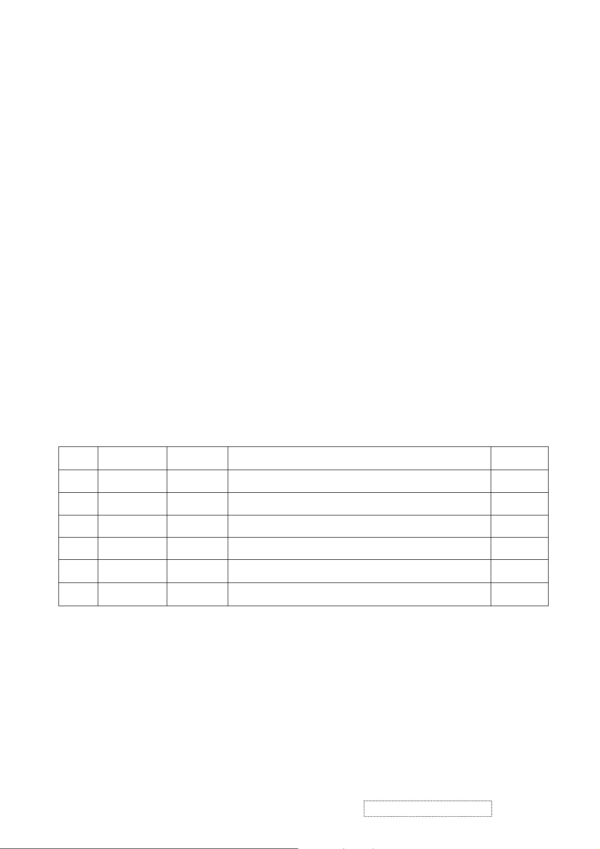
ECR Number
1a
05/26/05
Revision History
Description of Changes
Initial Release
EditorRevision SM Editing Date
A. Lu
ViewSonic Corporation Confidential
i
-
Do Not Copy VA915
Page 3

TABLE OF CONTENTS
1. Precautions and Safety Notices
2. Specification
3. Front Panel Function Control Description
4. Circuit Description
5. Adjustment Procedure
6. TroubleShooting Flow Chart
7. Recommended Spare Parts List
8. Exploded Diagram and Spare Parts List
9. Block Diagram
10. Schematic Diagrams
11. PCB Layout Diagrams
1
3
12
19
20
30
34
41
42
43
53
ViewSonic Corporation Confidential
ii
-
Do Not Copy VA915
Page 4

1. Precautions and Safety Notices
1. Appropriate Operation
(1) Turn off the product before cleaning.
(2) Use only a dry soft cloth when cleaning the LCD panel surface.
(3) Use a soft cloth soaked with mild detergent to clean the display housing.
(4) Use only high quality and safety approved AC/DC power cord.
(5) Disconnect the power plug from AC outlet if the product is not used for a long period of time.
(6) If smoke, abnormal noise, or strange odor is present, immediately switch the LCD display off.
(7) Do not touch the LCD panel surface with sharp or hard objects.
(8) Do not place heavy objects on the LCD display, video cable, or power cord.
(9) Do not use abrasive cleaners, waxes or solvents for your cleaning.
(10) Do not operate the product under the following conditions:
- Extremely hot, cold or humid environment.
- Areas susceptible to excessive dust and dirt.
- Near any appliance generating a strong magnetic field.
- Place in direct sunlight.
2. Caution
No modification of any circuit should be attempted. Service work should only be performed after you are thoroughly familiar
with all of the following safety checks and servicing guidelines.
3. Safety Check
Care should be taken while servicing this LCD display. Because of the high voltage used in the inverter circuit, the voltage is
exposed in such areas as the associated transformer circuits.
4. LCD Module Handling Precautions
4.1 Handling Precautions
(1) Since front polarizer is easily damaged, pay attention not to scratch it.
(2) Be sure to turn off power supply when inserting or disconnecting from input connector.
(3) Wipe off water drop immediately. Long contact with water may cause discoloration or spots.
(4) When the panel surface is soiled, wipe it with absorbent cotton or other soft cloth.
(5) Since the panel is made of glass, it may break or crack if dropped or bumped on hard surface.
(6) Since CMOS LSI is used in this module, take care of static electricity and insure human earth when handling.
(7) Do not open nor modify the Module Assembly.
(8) Do not press the reflector sheet at the back of the module to any directions.
(9) In case if a Module has to be put back into the packing container slot after once it was taken out from the
container, do not press the center of the CCFL Reflector edge. Instead, press at the far ends of the CFL
Reflector edge softly. Otherwise the TFT Module may be damaged.
(10) At the insertion or removal of the Signal Interface Connector, be sure not to rotate nor tilt the Interface
Connector of the TFT Module.
ViewSonic Corporation Confidential
1
-
Do Not Copy VA915
Page 5

(11) After installation of the TFT Module into an enclosure (LCD monitor housing, for example), do not twist nor
bend the TFT Module even momentary. At designing the enclosure, it should be taken into consideration that
no bending/twisting forces are applied to the TFT Module from outside. Otherwise the TFT Module may be
damaged.
(12) Cold cathode fluorescent lamp in LCD contains a small amount of mercury. Please follow local ordinances or
regulations for disposal.
(13) Small amount of materials having no flammability grade is used in the LCD module. The LCD module should
be supplied by power complied with requirements of Limited Power Source (IEC60950 or UL1950), or be
applied exemption.
(14) The LCD module is designed so that the CFL in it is supplied by Limited Current Circuit (IEC60950 or
UL1950). Do not connect the CFL in Hazardous Voltage Circuit.
ViewSonic Corporation Confidential
2
-
Do Not Copy VA915
Page 6
2. Specification
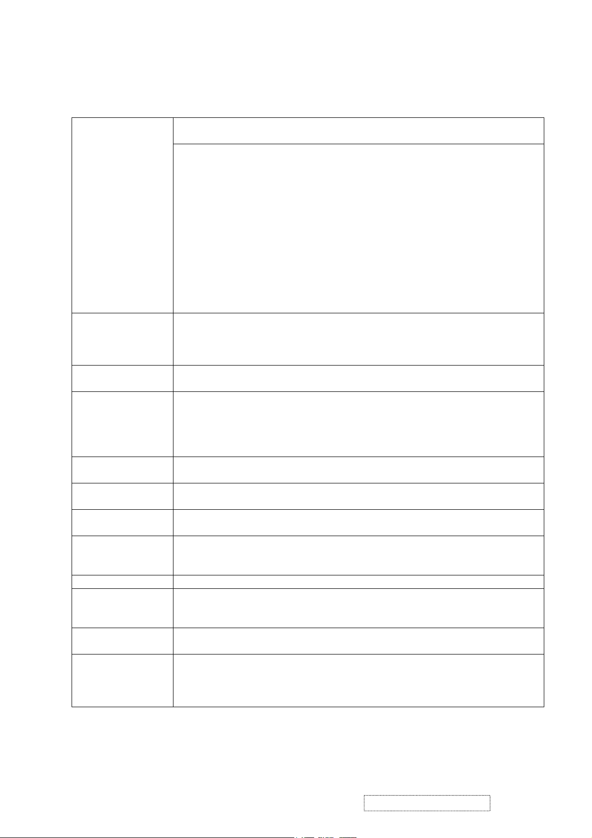
2.1 General Description
LCD
Fujitsu:
FLC48SXC8V-11E
CMO:
M190E2-L01
M190E3-L02
Input Signals
Active matrix thin-film-transistor (TFT) Type No: FLC48SXC8V-11E/
M190E2-L01 ;M190E3-L02
Active screen Size
Effective Display Size
Pixel Pitch
Pixel Format
Brightness
Contrast Ratio
Color (8 bits)
Viewing Angle range
(CR≧10, at Ta=25°C)
Backlight
19.0 inches diagonal
376.32mm (H) × 301.056mm (V)
0.294mm (H) × 0.294mm(V)
1280×1024 (SXGA )
250cd/m
2
(Typ.& CMO panel), 300cd/m2 (Typ.&
Fujitsu panel)
500:1 typ ( CMO E2 panel) , 1000:1 ( CMO E3 panel)
700:1 (Typ. & Fujitsu panel)
16,777,216 colors
Up 85° Down 85°(type)
Left 85° Right 85°(type)
4 CCFL
Analog RGB 0.7Vp-p / 75Ω
Digital RGB DVI Ver1.0 (TMDS Single Link)
H/V Separate sync. Sync 2.0~5.0Vp-p, Positive/Negative, 2.2KΩ
Input connector Analog D-sub 15 pin *1
Digital DVI-D 24pin *1
Synchronization Horizontal
Vertical
Non-interlaced
30 kHz to 82 kHz
50 Hz to 75 Hz
(automatically)
(automatically)
Maximum P ixel
Rated 135MHz
Resolution Horizontal
Vertical
Active Display Area Horizontal
Vertical
Power Supply
Voltage Rating
AC Power
Consumption
AC input
DC 12V
less than 60W
less than 1W
less than 1W
1280 dots
1024 lines
376.32 mm (typical, panel depends)
301.056 mm (typical, panel depends)
AC 100V~240V / 2A, 47.5~63Hz
4.5A.
On mode.
Active OFF mode.
DC Power OFF.
Current Rating AC input 1.5A @AC 100~240V.
Dimensions
Weight
Environmental
Conditions
Net
Gross
Depth(head only)
Net
Gross
Operating Temperature
Operating Humidity
Storage Temperature
Storage Humidity
442(W) x 405(H) x69.5 (D) mm
442(W) x 473.1(H) x 181.2(D) mm (With stand base)
181.2mm
7.5 Kg
10.3 Kg
0 to 40°C
20 to 85%
-20 to 60°C
5 to 85% (non-condensation)
ViewSonic Corporation Confidential
3
-
Do Not Copy VA915
Page 7

Accessories AC cable
User Guide
CD Rom
Warranty Card
HD15 - HD15 cable
DVI(D) - DVI(D) cable
1.83m
English
1
1
1
1
Regulatory Standards UL, cUL, FCC-B, CB, CE, EnergyStar, ENERGY, NOM, TUV/GS, TUV ERGO
(covers ISO13406-2 & MPRII), TCO99(VG910b)or TCO03(VG910s), GOST-R +
20 ORIGINAL COPIES HYGIENIC,(SASO), PCBC, VCCI,
BSMI,CCC(PSB),(C-TICK), TUV-S,Taiwan green mark,PCT(BZ02)
Others Tilt Angle 20° up / 5° down
VESA DDC 2B compatible
2.2 Electrical Characteristics
2.2.1 Power Supply
AC Input Voltage AC 100~240V / 47.5~63Hz
Power Consumption:
Less than 60W On mode
Less than 1W Active Off mode
Less than 1W DC power Off
Current Rating 1.5A @ AC 100~240V
Inrush Current :
Less than 50 Amp(peak) for 120 VAC
Less than 100 Amp(peak) for 220 VAC
Power cord:detachable, 3P, 1.83m
2.2.2 LCD
LCD Active matrix thin-film-transistor (TFT)
Active screen size 19.0 inches (376.32mm × 301.056mm) diagonal
Pixel Format 1280 x 1024 (SXGA )
R.G.B. stripe arrangement
Display method TFT, normally Black
Pixel pitch 0.294 (H) x 0.294 (V) mm
Dot number 1280 x 1024 x 3 dots
Backlight Edge-lighting type with 4 CCFL
(Cold Cathode Fluorescent Lamp)
Brightness 250 cd/m
Contrast ratio ( Typ) 500:1 (CMO E2 panel), 1000:1 (CMO E3 panel );700:1
2
(Typ. & CMO panel), 300 cd/m2 (Typ. & Fujitsu panel)
( Fujitsu
panel)
Display color 16,777,216 colors
viewing angle typical Up 85° / down 85° / right 85° / left 85°
(Contrast ratio≧10 at Ta=25°C / 77°F)
Response time (Typ) Rise time 15mS, Fall time 10mS.
Rise time 13mS, Fall time 7mS for CMO E3 panel
2.2.3 Power Management
VG910 will enter power saving mode under the following conditions:
Power Management condition and status in AC 240V
ViewSonic Corporation Confidential
4
-
Do Not Copy VA915
Page 8
State
Signals
Horizontal Vertical Video
Power
Supply
On Pulses Pulses Active <50W Green
Active off
Pulse No Pulse
No Pulse Pulse
Blank
<1W
No Pulses No Pulses
Out off scan range
<30KHz ,
>82KHz
<50Hz ,
>75Hz
-
<5 0W
AC power Off - - - Off Off
DC power Off - - - <1W Off
2.3 Video alignment
2.3.1 COLOR TEMPERATURE ALLIGMENT
a. APPLY VESA 1280x1024 / 60Hz , FULL WHITE PATTERN.( INPUT SIGNAL LEVEL
=0.7Vp-p )
b. AUTO WHITE BANLANCE MUST BE FINISH AT 32 GRAY PATTERN BEFORE AUTO
ALIGNMENT,
c. SET DEFAULT Æ CONTRAST TO 70% , BRIGHTNESS TO 100%
9300°K, 6500°K,:R G B SUB-BRIGHTNESS SET AS BELOW
LED
Amber
Green
R SUB-BRIGHTNESS 128 128 128 128
G SUB-BRIGHTNESS 128 128 128 128
B SUB-BRIGHTNESS 128 128 128 128
SET BLACKLEVEL = 255, GAMMA=OFF AT FACTORY DEFAULT.
SET BRIGHTNESS =134 AT FACTORY DEFAULT FOR FUJITSU PANEL
SET BRIGHTNESS =130 AT FACTORY DEFAULT FOR CMO PANEL
2.3.2 DIGITAL ALIGNMENT
2.3.2.1 APPLY VESA 1280x1024 / 60Hz , FULL WHITE PATTERN ,
2.3.2.2 ADJUST R, G, B SUB-CONTRAST TO MEET FOLLOWING CHROMATICITY
SPEC.
x = 0.313 ±0.003 , y = 0.329 ±0.003
2.3.3 ANALOG ALIGNMENT
2.3.3.1 9300°K HIGH LUMINANCE ALIGNMENT
2.3.3.1.1 APPLY VESA 1280x1024 / 60Hz , FULL W HITE PATTERN.
2.3.3.1.2 ADJUST R, G, B SUB-CONTRAST TO MEET FOLLOW ING
9300°K 6500°K 5400°K 5000°K
CHROMATICITY SPEC.
9300°K → x = 0.283 ±0.003, y = 0.298 ±0.003 , Y > 155 cd/m
2
2.3.3.2 6500°K HIGH LUMINANCE ALIGNMENT
2.3.3.2.1 APPLY VESA 1280x1024 / 60Hz , FULL WHITE PATTERN.
2.3.3.2.2 ADJUST R, G, B SUB-CONTRAST TO MEET FOLLOWING
CHROMATICITY SPEC.
6500°K → x = 0.313±0.003, y = 0.329 ±0.003 , Y > 190 cd/m
ViewSonic Corporation Confidential
5
2
-
Do Not Copy VA915
Page 9

2.3.3.3 5400°K HIGH LUMINANCE ALIGNMENT
2.3.3.3.1 APPLY VESA 1280x1024 / 60Hz , FULL WHITE PATTERN.
2.3.3.3.2 ADJUST R, G, B SUB-CONTRAST TO MEET FOLLOWING
2.3.3.4 5000°K HIGH LUMINANCE ALIGNMENT
2.3.3.4.1 APPLY VESA 1280x1024 / 60Hz , FULL WHITE PATTERN.
2.3.3.4.2 ADJUST R, G, B SUB-CONTRAST TO MEET FOLLOWING
2.3.4 LUMINANCE TEST
2.3.4.1 SET COLOR Temperature TO 9300°K
APPLY VESA 1280x1024/60Hz , APPLY FULL WHITE PATTERN, ADJUST
OSD BRIGHTNESS = 100%, CONTRAST = 70%.
1. THE LUMINANCE MEASURE SHOULD BE OVER 155cd/m
2.3.4.2 SET COLOR Temperature TO 6500°K
APPLY VESA 1280x1024 / 60Hz , APPLY FULL WHITE PATTERN, ADJUST
OSD BRIGHTNESS = 100%, CONTRAST = 70%
1. THE BRIGHTNESS MEASURE SHOULD BE OVER 190cd/m
2. SET BRIGHTNESS =100% , CONTRAST=100% ,THE LUMINANCE
2.3.4.3 SET COLOR Temperature TO 5400°K
APPLY VESA 1280x1024 / 60Hz , APPLY FULL WHITE PATTERN, ADJUST
OSD BRIGHTNESS = 100%, CONTRAST = 70%
1. THE BRIGHTNESS MEASURE SHOULD BE OVER 180cd/m
2.3.4.4 SET COLOR Temperature TO5000°K
APPLY VESA 1280x1024 / 60Hz , APPLY FULL WHITE PATTERN, ADJUST
OSD BRIGHTNESS = 100%, CONTRAST = 70%
1. THE BRIGHTNESS MEASURE SHOULD BE OVER 180 cd/m
2.3.4.5 APPLY VESA 1280x1024/60Hz , APPLY FULL WHITE PATTERN, ADJUST
OSD BRIGHTNESS 100%, CONTRAST 70% ,
MEASUREMENT AT CENTER OF SCREEN
CHROMATICITY SPEC.
5400°K → x = 0.335 ±0.003, y = 0.350 ± 0.003 , Y > 180cd/m
CHROMATICITY SPEC.
5000°K → x = 0.346 ±0.003, y = 0.359 ±0.003 , Y > 180cd/m
2
2
MEASURE SHOULD BE OVER 220cd/m
2
2
2
MODE X y Y
9300°K 0.283±0.010 0.298 ±0.010
6500°K 0.313 ±0.010 0.329 ±0.010
5400°K 0.335 ±0.010 0.350 ±0.010
5000°K 0.346 ±0.010 0.359 ±0.010
OVER 155 cd/m
OVER190 cd/m
OVER 180 cd/m
OVER 180 cd/m
2
2
2
2
2
2
ViewSonic Corporation Confidential
6
-
Do Not Copy VA915
Page 10

2.5 EDID SERIAL NO. FORMAT
2.5.1 EDID for VA915 (FLC48SXC8V-11E)
2.5.1.1 Analog EDID
128 BYTES OF EDID CODE:
0 1 2 3 4 5 6 7 8 9
0 00 FF FF FF FF FF FF 00 5A 63
10 18 DA 01 01 01 01 01 0E 01 03
20 0E 26 1E 78 2E C2 75 A3 5A 4A
30 9F 24 13 50 54 BF EF 80 81 80
40 81 40 71 4F 01 01 01 01 01 01
50 01 01 01 01 30 2A 00 98 51 00
60 2A 40 30 70 13 00 78 2D 11 00
70 00 1E 00 00 00 FF 00 41 33 31
80 30 34 30 31 30 30 30 30 31 0A
90 00 00 00 FD 00 32 4B 1E 52 0E
100 00 0A 20 20 20 20 20 20 00 00
110 00 FC 00 56 47 39 31 30 73 0A
120 20 20 20 20 20 20 00 CC
2.5.1.2 Digital EDID
128 BYTES OF EDID CODE:
0 1 2 3 4 5 6 7 8 9
0 00 FF FF FF FF FF FF 00 5A 63
10 18 DA 01 01 01 01 01 0E 01 03
20 80 26 1E 78 2E C2 75 A3 5A 4A
30 9F 24 13 50 54 BF EF 80 81 80
40 81 40 71 4F 31 0A 01 01 01 01
50 01 01 01 01 30 2A 00 98 51 00
60 2A 40 30 70 13 00 78 2D 11 00
70 00 1E 00 00 00 FF 00 41 33 31
80 30 34 30 31 30 30 30 30 31 0A
90 00 00 00 FD 00 32 4B 1E 52 0E
100 00 0A 20 20 20 20 20 20 00 00
110 00 FC 00 56 47 39 31 30 73 0A
120 20 20 20 20 20 20 00 21
ViewSonic Corporation Confidential
7
-
Do Not Copy VA915
Page 11
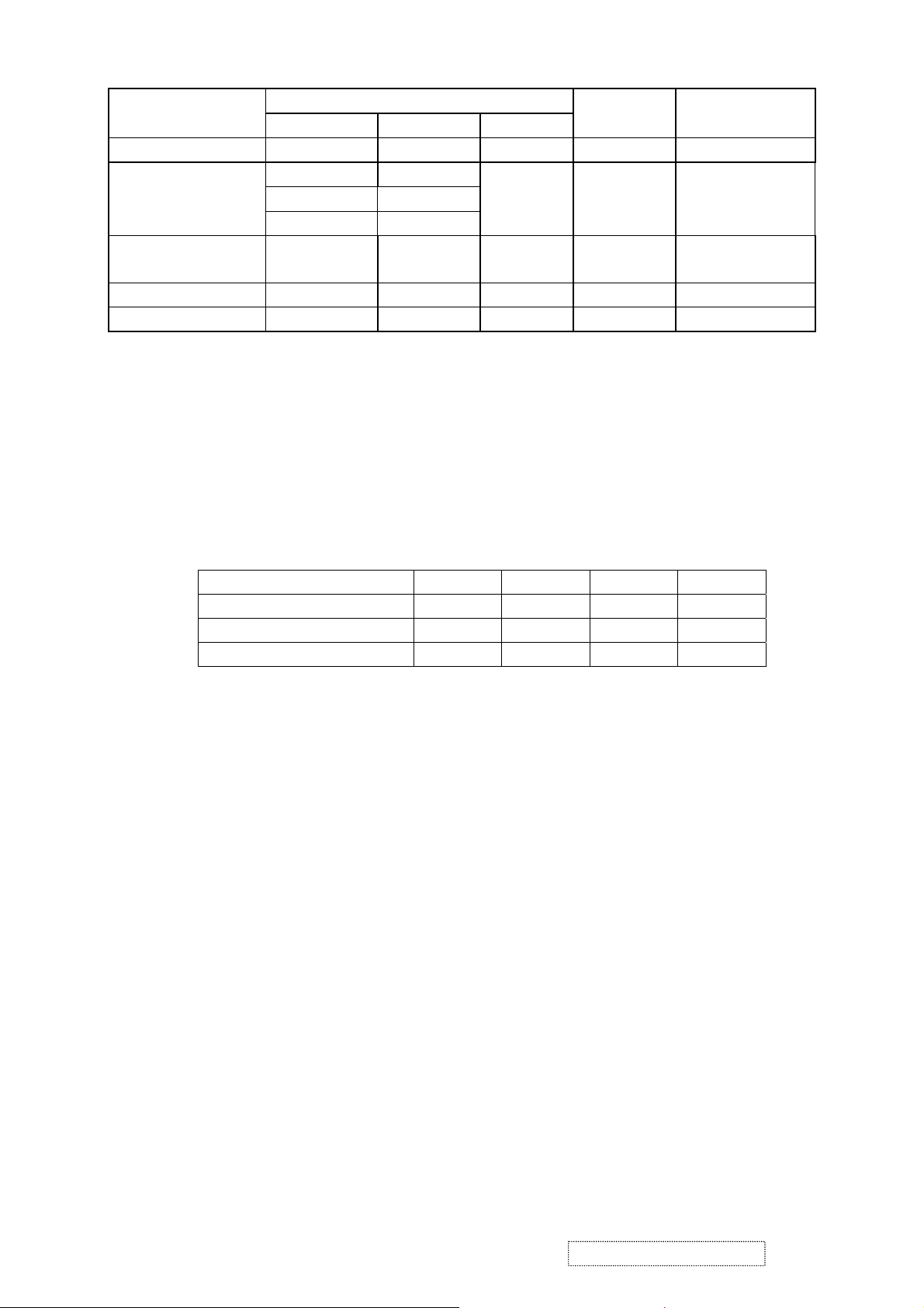
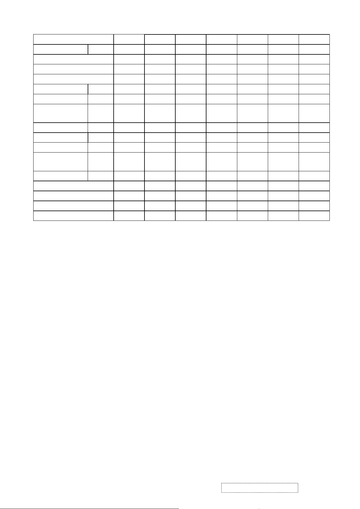
APPENDIX A : PRESET TIMING CHART
Analog Mode
1 2 3 4 5 6 7
Signal name
symbol
TEXT
mode
TEXT
mode
VGA MAC-II VESA-VGA VESA-VGA VESA-VGA
H-frequency (kHz) 31.468 31.469 31.468 35.001 37.5 37.862 43.269
V-frequency (Hz)
Pixel rate (MHz)
H-sync Ths
H-back porch Thb
Count num (H-total) Thd
H- front porch Thf
V-sync Tvs
V-back porch Tvb
Count num (V-total) Tvd
V-front porch Tvf
H-sync. Polarity
V-sync Polarity
H-resolution (dots)
V-resolution (lines)
70.087 70.087 59.941 66.667 75 72.807 85.005
25.175 28.322 25.175 30.240 31.5 31.501 36.000
96 108 96 64 64 40 56
48 54 48 96 120 128 80
800 900 800 864 840 832 832
16 18 16 64 16 24 56
2 2 2 3 3 3 3
60 35 33 39 16 28 25
449 449 525 525 500 520 509
37 12 10 3 1 9 1
Positive Negative Negative Negative Negative Negative Negative
Negative Positive Negative Negative Negative Negative Negative
640 720 640 640 640 640 640
350 400 480 480 480 480 480
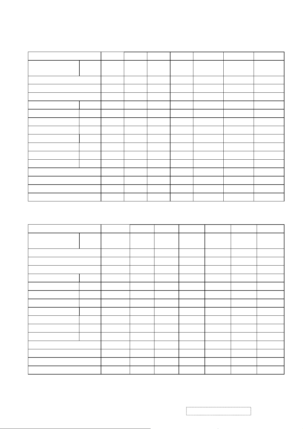
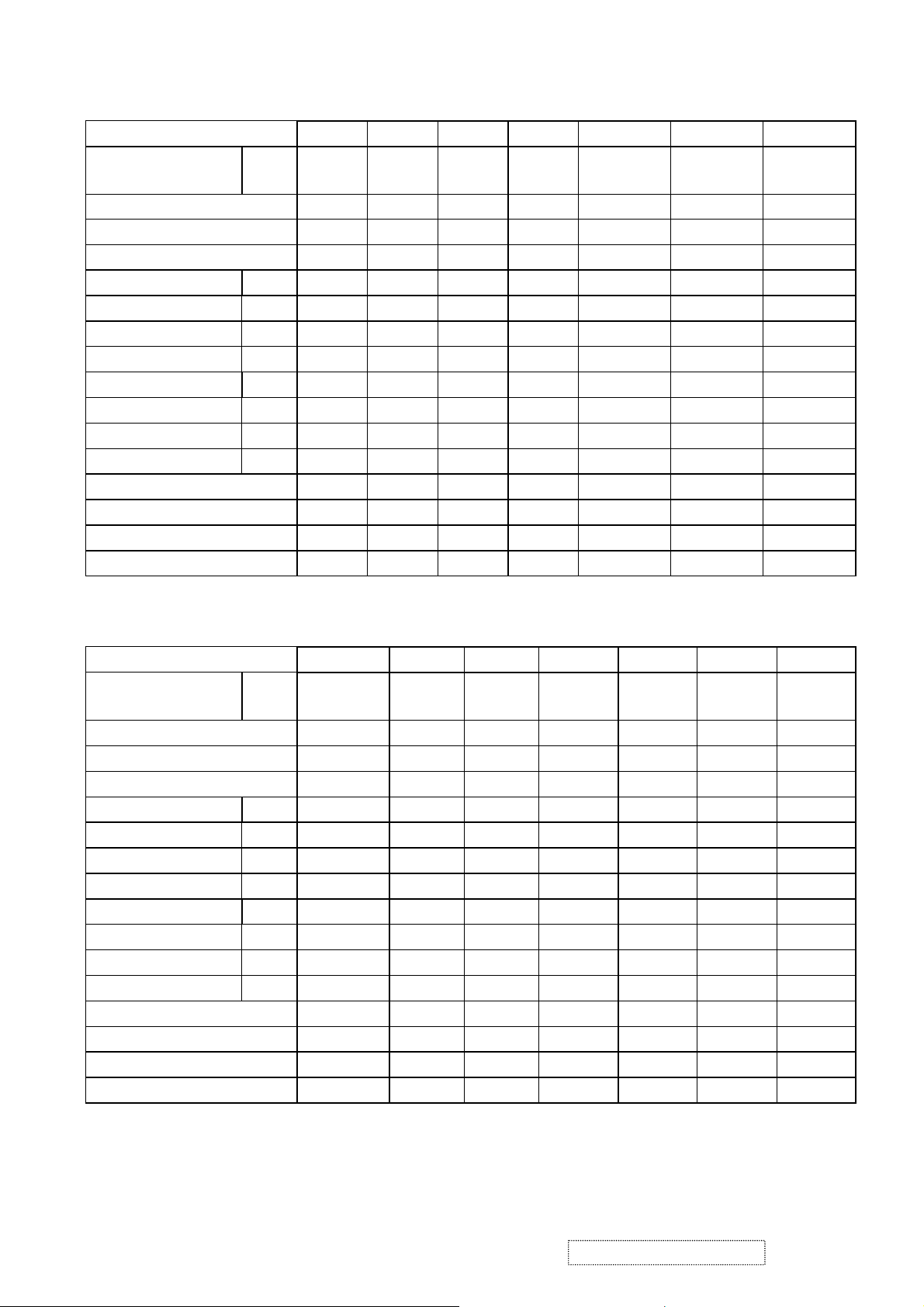
8 9 10 11 12 13 14
Signal name Symbol
IBM-8514
A
SVGA SVGA SVGA SVGA MAC 16" XGA
H-frequency (kHz) 35.156 37.879 48.077 46.875 53.674 49.725 48.363
V-frequency (Hz) 56.250 60.317 72.188 75.000 85.061 74.5 60.004
Pixel rate (MHz) 36.000 40.000 50.000 49.500 56.250 57.283 65.000
H-sync Ths 72 128 120 80 64 64 136
H-back porch Thb 128 88 64 160 152 224 160
Count num (H-total) Thd 1024 1056 1040 1056 1048 1152 1344
H- front porch Thf 24 40 56 16 32 32 24
V-sync Tvs 2 4 6 3 3 3 6
V-back porch Tvb 22 23 23 21 27 39 29
Count num (V-total) Tvd 625 628 666 625 631 667 806
V-front porch Tvf 1 1 37 1 1 1 3
H-sync. Polarity Negative Positive Positive Positive Positive Negative Negative
V-sync Polarity Negative Positive Positive Positive Positive Negative Negative
H-resolution (dots) 800 800 800 800 800 832 1024
V-resolution (lines) 600 600 600 600 600 624 768
ViewSonic Corporation Confidential
8
-
Do Not Copy VA915
Page 12
15 16 17 18 19 20 21
Signal name Symbol XGA XGA XGA XGA SXGA 720P SXGA
H-frequency (kHz) 56.476 58.099 60.023 68.677 63.981 45.000 79.976
V-frequency (Hz) 70.069 72.082 75.029 84.997 60.02 60.00 75.025
Pixel rate (MHz) 75.000 78.084 78.750 94.500 108 74.250 135
H-sync Ths 136 136 96 96 112 40 144
H-back porch Thb 144 160 176 208 248 270 248
Count num
Thd 1328 1344 1312 1376 1688 1658 1688
(H-total)
H- front porch Thf 24 24 16 48 48 60 16
V-sync Tvs 6 6 3 3 3 5 3
V-back porch Tvb 29 29 28 36 38 20 38
Count num
Tvd 806 806 800 808 1066 750 1066
(V-total)
V-front porch Tvf 3 3 1 1 1 5 1
H-sync. Polarity Negative Negative Positive Positive Po sitive Negative Positive
V-sync Polarity Negative Negative Positive Positive Positive Negative Positive
H-resolution (dots) 1024 1024 1024 1024 1280 1280 1280
V-resolution (lines) 768 768 768 768 1024 720 1024
Notes: Because this model no support FRC and in order to meet the panel spec of vertical frequency,
some timing can not full screen in vertical size.
Ex:640x400/70Hz;640x350/70Hz ;720x400/70Hz ;640x480/85Hz;800x600/85Hz;
1024x768/85Hz.
ViewSonic Corporation Confidential
9
-
Do Not Copy VA915
Page 13
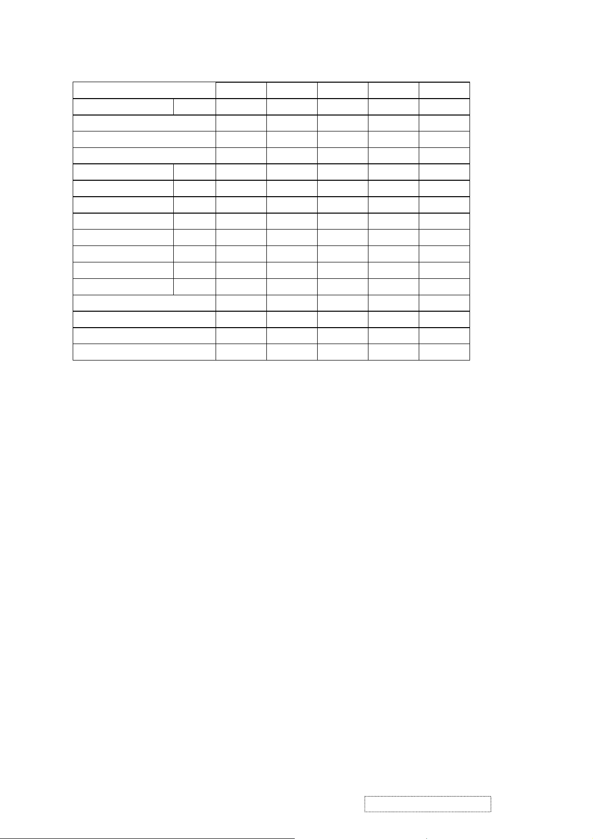
Digital Mode
1 2 3 4 5 6 7
Signal name symbol TEXT
mode
TEXT
mode
VGA VGA VESA-VGA VESA-VGA VESA-VGA
H-frequency (kHz) 31.468 31.469 31.468 31.468 37.5 37.862 43.269
V-frequency (Hz) 70.087 70.087 70.000 59.941 75 72.807 85.005
Pixel rate (MHz) 25.175 28.322 25.175 25.175 31.5 31.501 36.000
H-sync Ths 96 108 96 96 64 40 56
H-back porch Thb 48 54 48 48 120 128 80
Count num (H-total) Thd 800 900 800 800 840 832 832
H- front porch Thf 16 18 16 16 16 24 56
V-sync Tvs 2 2 2 2 3 3 3
V-back porch Tvb 60 35 35 33 16 28 25
Count num (V-total) Tvd 449 449 449 525 500 520 509
V-front porch Tvf 37 12 10 6 1 9 1
H-sync. Polarity Positive Negative Negative Negative Negative Negative Negative
V-sync Polarity Negative Positive Negative Negative Negative Negative Negative
H-resolution (dots) 640 720 640 640 640 640 640
V-resolution (lines) 350 400 400 480 480 480 480
8 9 10 11 12 13 14
Signal name Symbol IBM-8514A SVGA SVGA SVGA SVGA XGA XGA
H-frequency (kHz) 35.156 37.879 48.077 46.875 53.674 48.363 56.476
V-frequency (Hz) 56.250 60.317 72.188 75.000 85.061 60.004 70.069
Pixel rate (MHz) 36.000 40.000 50.000 49.500 56.250 65.000 75.000
H-sync Ths 72 128 120 80 64 136 136
H-back porch Thb 128 88 64 160 152 160 144
Count num (H-total) Thd 1024 1056 1040 1056 1048 1344 1328
H- front porch Thf 24 40 56 16 32 24 24
V-sync Tvs 2 4 6 3 3 6 6
V-back porch Tvb 22 23 23 21 27 29 29
Count num (V-total) Tvd 625 628 666 625 631 806 806
V-front porch Tvf 1 1 37 1 1 3 3
H-sync. Polarity Negative Positive Positive Positive Positive Negative Negative
V-sync Polarity Negative Positive Positive Positive Positive Negative Negative
H-resolution (dots) 800 800 800 800 800 1024 1024
V-resolution (lines) 600 600 600 600 600 768 768
ViewSonic Corporation Confidential
10
-
Do Not Copy VA915
Page 14
15 16 17 18 19
Signal name Symbol XGA XGA XGA SXGA HD-720P
H-frequency (kHz) 58.099 60.023 68.677 63.981 45.000
V-frequency (Hz) 72.082 75.029 84.997 60.02 60.00
Pixel rate (MHz) 78.084 78.750 94.500 108 74.250
H-sync Ths 136 96 96 112 40
H-back porch Thb 160 176 208 248 270
Count num (H-total) Thd 1344 1312 1376 1688 1658
H- front porch Thf 24 16 48 48 60
V-sync Tvs 6 3 3 3 5
V-back porch Tvb 29 28 36 38 20
Count num (V-total) Tvd 806 800 808 1066 750
V-front porch Tvf 3 1 1 1 5
H-sync. Polarity Negative Positive Po sitive Positive Negative
V-sync Polarity Negative Positive Positive Positive Negative
H-resolution (dots) 1024 1024 1024 1280 1280
V-resolution (lines) 768 768 768 1024 720
Notes: Because this model no support FRC and in order to meet the panel spec of vertical frequency,
some timing can not full screen in vertical size.
Ex:640x400/70Hz;640x350/70Hz ;720x400/70Hz ;640x480/85Hz;800x600/85Hz;
1024x768/85Hz.
ViewSonic Corporation Confidential
11
-
Do Not Copy VA915
Page 15
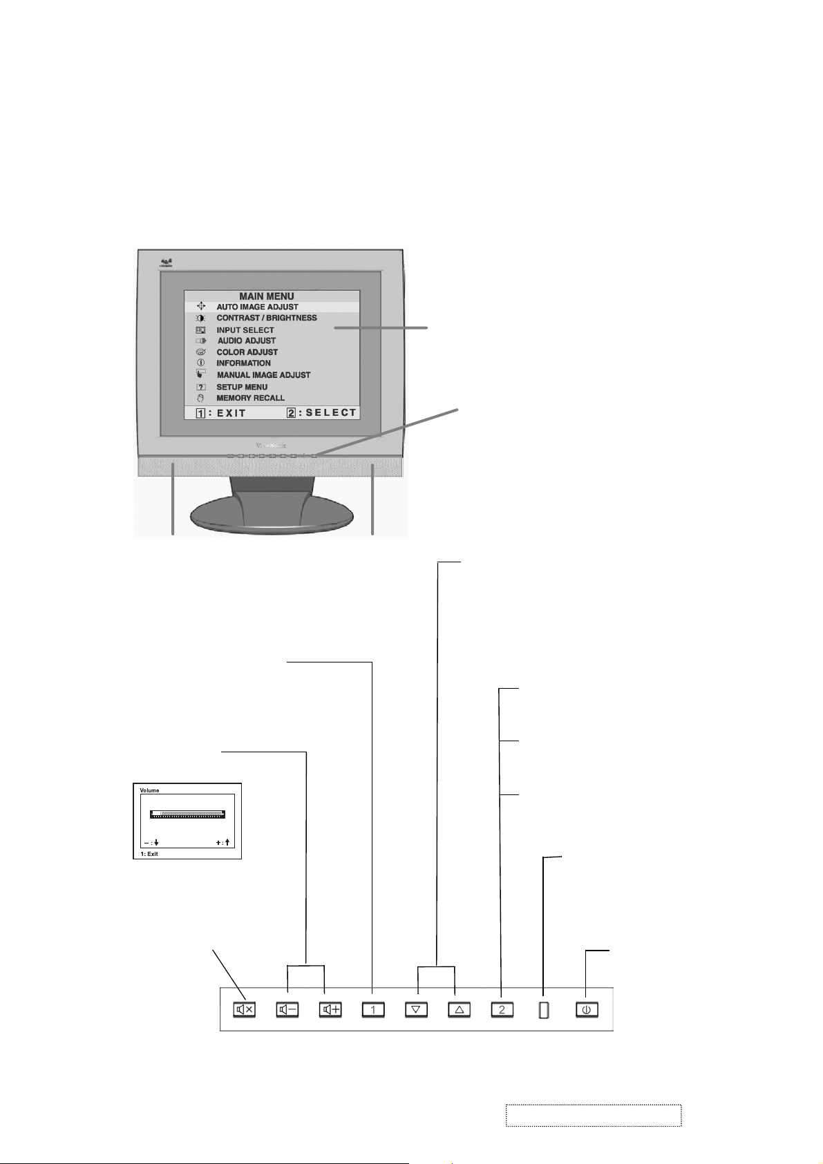
3. Front Panel Function Control Description
Adjusting the Screen Image
Use the buttons on the front control panel to display and adjust the OnView
®
controls which display on the screen. The OnView controls are explained at the
top of the next page.
Main Menu with OnView controls
Front Control Panel shown
below
Speaker Speaker
Scrolls through menu options and
adjusts the displayed control.
Also a shortcut to display the
Contrast adjustment control
screen.
Displays the Main Menu
or exits the control screen
and saves adjustments
Decreases or
increases volume
Audio Mute button
turns the sound off.
Displays the control
screen for the highlighted
control.
Also toggles between two
controls on some
screens.
Also a shortcut to toggle
between analog and
digital connections.
Power light
Green = ON
Orange = Power
Saving
Power
On/Off
ViewSonic Corporation Confidential
12
-
Do Not Copy VA915
Page 16
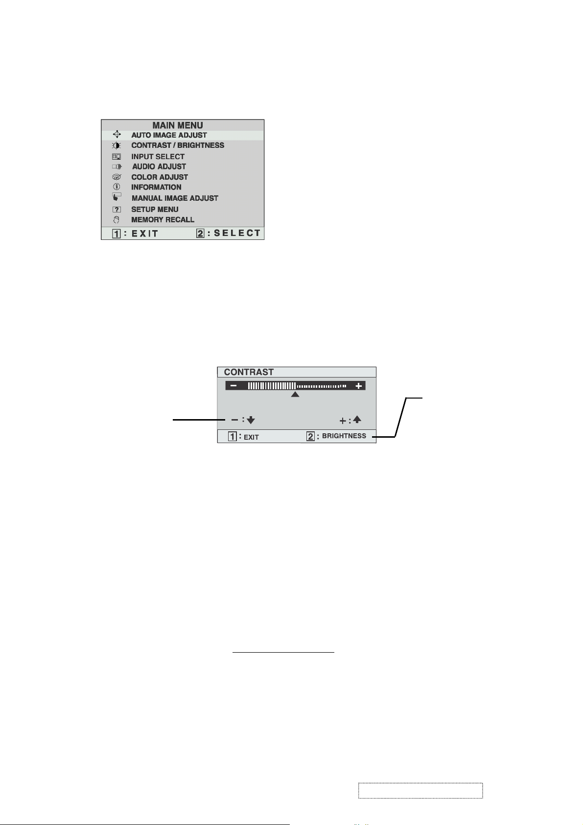
Do the following to adjust the screen image:
To display the Main Menu, press button [1].
1
NOTE:
All OnView menus and adjustment screens disappear automatically
after about 30 seconds.
To select a control you want to adjust, press ▲ or ▼ to scroll up or down the
2
Main Menu.
After the control is selected, press button [2]. A control screen like the one
3
shown below appears.
The line at the
The ▼down
arrow decreases,
▲
up arrow
increases
To adjust the control, press the up ▲ or down ▼ buttons.
4
To save the adjustments and exit the menu, press button [1]
5
bottom of the
screen tells you
what you can do
next: Exit or select
the Brightness
control.
.
twice
The following tips may help you optimize your display:
• Adjust your computer's graphic card so that it outputs a video signal 1280 x
1024 @ 60 Hz to the LCD display. (Look for instructions on "changing the
refresh rate" in your graphic card's user guide.)
• If necessary, make small adjustments using H POSITION and V POSITION
until the screen image is completely visible
. (The black border around the
edge of the screen should barely touch the illuminated "active area" of the
LCD display.)
ViewSonic Corporation Confidential
13
-
Do Not Copy VA915
Page 17
Main Menu Controls
Adjust the menu items shown below by using the up ▲ and down ▼ buttons.
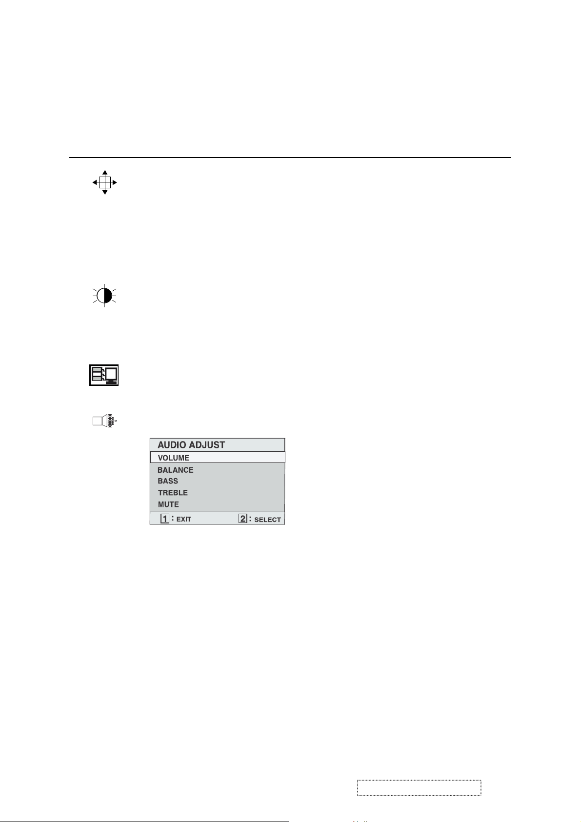
Control Explanation
Auto Image Adjust
automatically sizes, centers, and fine tunes
the video signal to eliminate waviness and distortion.
Press the [2] button to obtain a sharper image.
NOTE: Auto Image Adjust works with most common video
cards. If this function does not work on your LCD display, then
lower the video refresh rate to 60 Hz and set the resolution to its
pre-set value.
Contrast
adjusts the difference between the image background
(black level) and the foreground (white level).
Brightness
Input Select
adjusts background black level of the screen image.
toggles between inputs if you have more than one
computer connected to the VG910b/VG910s.
Audio Adjust
Volume
increases the volume, decreases the volume, and mutes
the audio.
Balance
adjusts the proportion of sound coming from each
speaker.
Bass
Tre bl e
Mute
ViewSonic Corporation Confidential
adjusts the low (bass) frequency audio output.
adjusts the high (treble) frequency audio output.
temporarily silences audio output.
14
-
Do Not Copy VA915
Page 18
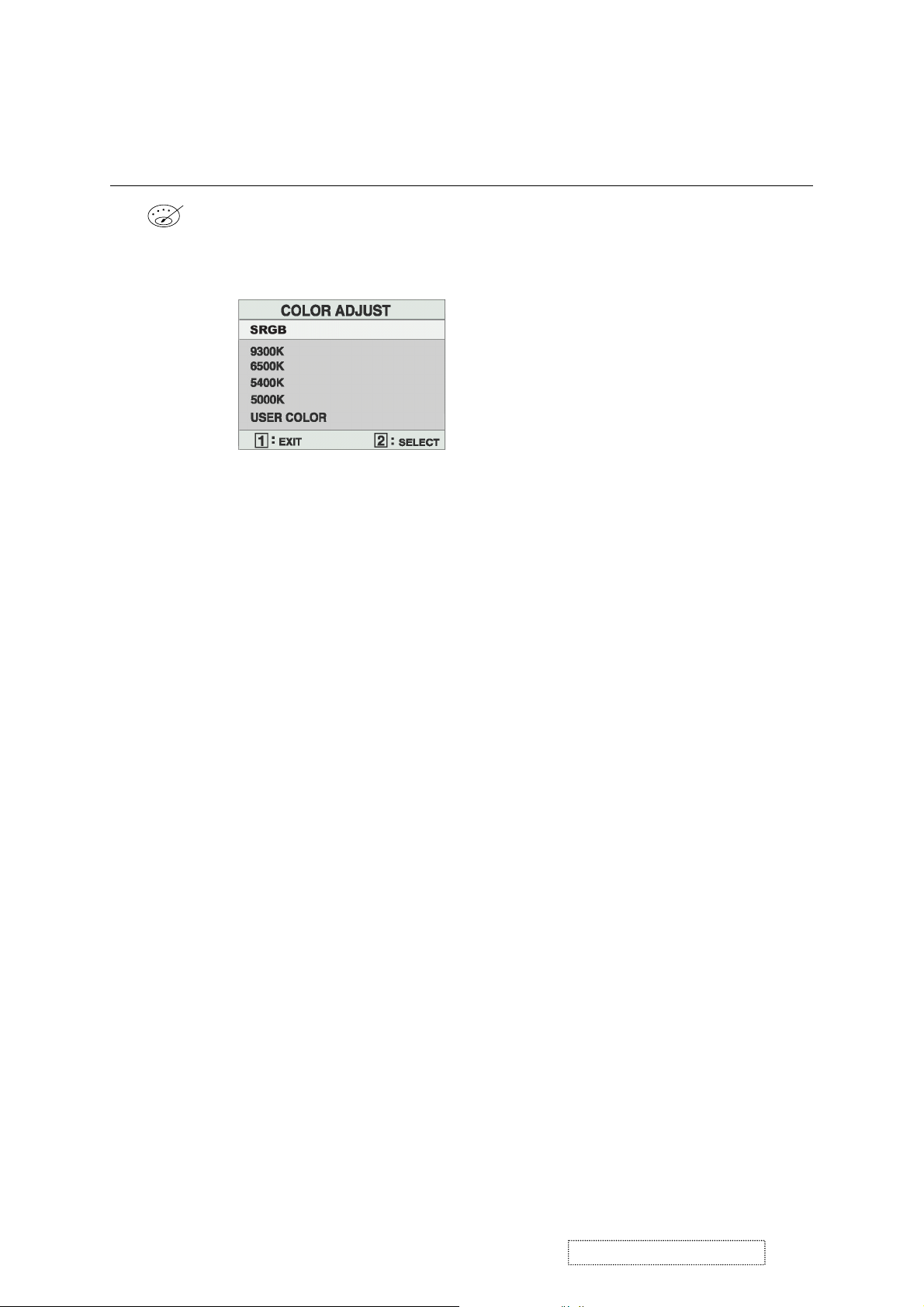
Control Explanation
Color Adjust
color temperatures and
provides several color adjustment modes: preset
RGB
which allows you to adjust red (R),
green (G), and blue (B) separately. The factory setting for this
product is 6500K (6500 Kelvin).
sRGB
— sRGB is quickly becoming the industry standard for
color management, with support being included in many of the
latest applications. Enabling this setting allows the LCD display
to more accurately display colors the way they were originally
intended. Enabling the sRGB setting will cause the Contrast and
Brightness adjustments to be disabled.
9300K
— Adds blue to the screen image for cooler white (used
in most office settings with fluorescent lighting).
6500K
— Adds red to the screen image for warmer white and
richer red.
5400K
5000K
— Adds green to the screen image for a darker color.
— Adds blue and green to the screen image for a darker
color.
User Color
and blue (B)
To select color (R, G or B) press button [2].
1
To adjust selected color, press ▲ or ▼.
2
Important
— Individual adjustments for red (R), green (G),
.
: If you select RECALL from the Main Menu when
the product is set to a Preset Timing Mode, colors return to the
6500K factory preset.
ViewSonic Corporation Confidential
15
-
Do Not Copy VA915
Page 19
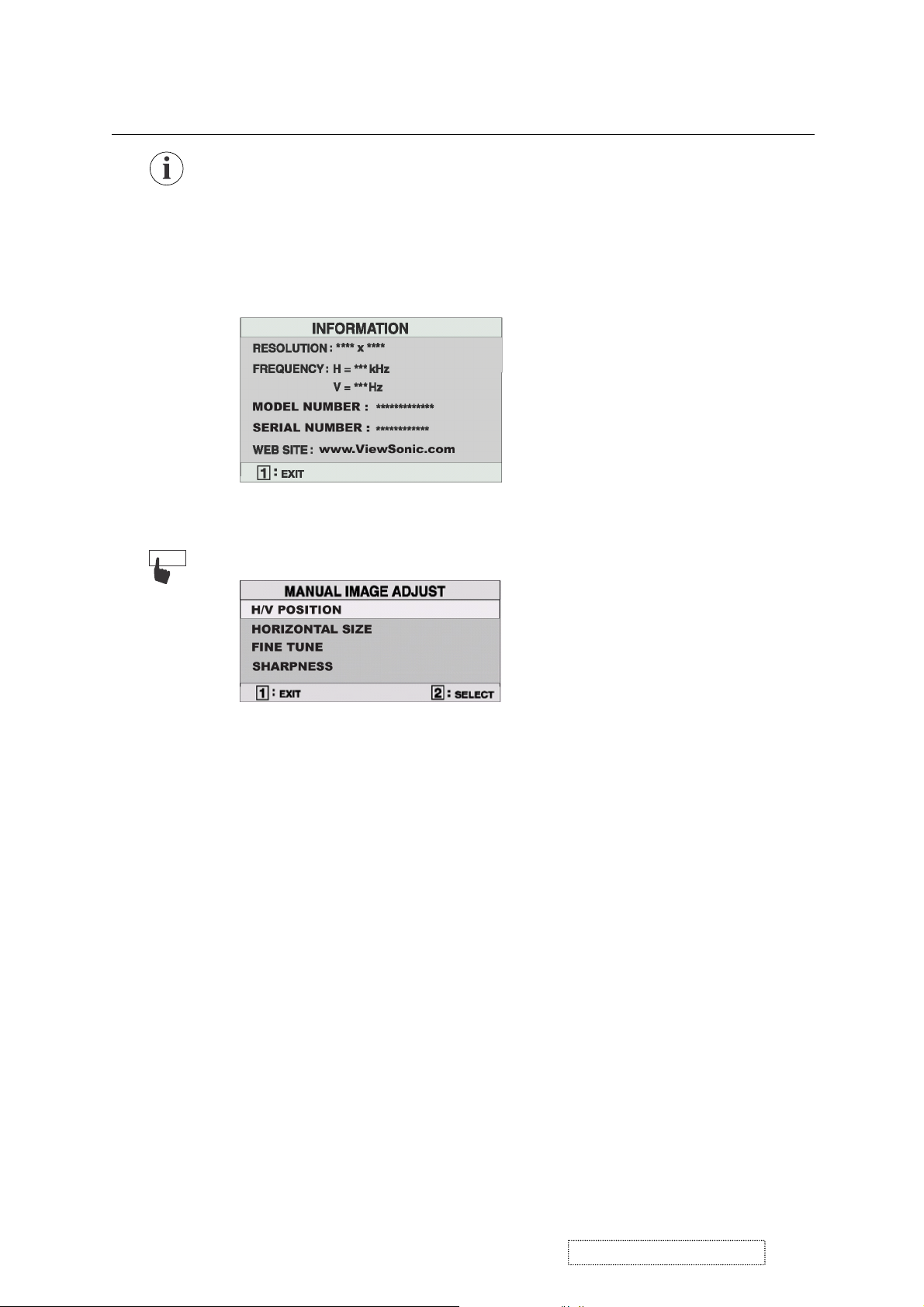
Control Explanation
Information
displays the timing mode (video signal input)
coming from the graphics card in your computer. See your
graphic card’s user guide for instructions on changing the
resolution and refresh rate (vertical frequency).
NOTE:
VESA 1280 x 1024 @ 60 Hz (recommended) means
that the resolution is 1280 x 1024 and the refresh rate is 60
Hertz.
Manual Image Adjust
displays the Manual Image Adjust menu.
The
Manual Image Adjust
Horizontal Position
Vertical Position
Horizontal Size
Fine Tune
sharpens focus by aligning the illuminated text and/
moves the screen image left or right.
moves the screen image up or down.
adjusts the width of the screen image.
or graphic characters.
Sharpness
adjusts the clarity and focus of the screen image.
controls are explained below:
ViewSonic Corporation Confidential
16
-
Do Not Copy VA915
Page 20

Control Explanation
Setup Menu
The
Setup Menu
Language
displays the menu shown below.
controls are explained below:
allows you to choose the language used in the menus
and control screens.
Resolution Notice
below.
displays the Resolution Notice menu shown
Resolution Notice
OSD Position
advises the optimal resolution to use.
allows you to move the on-screen display menus
and control screens.
OSD Timeout
sets the length of time an on-screen display
screen is displayed. For example, with a “15 second” setting, if
a control is not pushed within 15 seconds, the display screen
disappears.
OSD Background
allows you to turn the On-Screen-Display
background on or off.
Memory Recall
returns adjustments to the original factory
settings if the display is operating in a factory Preset Timing
Mode listed in this user guide.
Exception:
This control does not affect changes made with the
User Color control.
ViewSonic Corporation Confidential
17
-
Do Not Copy VA915
Page 21

Special key (Hot ke y): Press follo ws key at turning on momentary.
Key
“Vol -”
○
Key
“Vol +”
○ ○
Key “1”
○
○ ○
○
○ ○
Key
“DOWN”
Key
“UP”
○
○ ○ ○
○
Key “2” power functions
○
○
○ ○
Factory mode
Burn in off
Burn in on
All mode recall
Lock(Unlock)
Power Key
○
Lock(Unlock)
Osd Key
Read EDID
ViewSonic Corporation Confidential
18
-
Do Not Copy VA915
Page 22

4. Circuit Description
4.1 Power supply (DC/DC Converter):
4.1.1 IC251 MP1583 is a switching regulator controller that uses PWM method. That can be used for DC to
DC conversion for step-down. It converts a 12V DC into regulated and stable output voltage of 5V
respectively.
4.1.2 Regulator:
IC253 function is convert a 5V into regulated and stable O/P 3.3V.
IC252,Q255 are a 3.3V convert into O/P2.5V.
4.2 DDC data select:
4.2.1 IC600(AT24C02) is save D-SUB DDC data.
4.2.2 IC602(AT24C02) is save DVI, DDC data.
4.3 FLASH MEMORY
The IC402(A290011TL-70) is 128K X 8 Bit CMOS 5.0 Volt-only Flash Memory for Program save.
It Embedded Erase Algorithms Will automatically erase the entire chip or any combination of designed sector and
verify the erase sectors; Embedded Program algorithm automatically writes and verifies bytes at specified addresses
4.4 MCU/Scalar
The MCU control the keyboard signal and audio signal.
The GM5120 is a high performance, graphics processing IC for LCD monitors with resolutions at SXGA. On-chip
function include a high-speed triple-ADC and PLL, Ultra-Reliable DVI receiver, a high quality zoom and shrink
scaling engine, an on-screen display(OSD) controller, digital color controls and on-chip microcontroller (OCM),
5-Volt tolerance inputs ,low EMI and power management.
The analog input (CN602) signal and DVI-D input(CN601) signal are designed to be connected directly to scalar IC,
The MST9131A built-in LVDS transmitter, it is designed to be connected directly to panel.
4.5 Audio processor
IC802(PT2313L) is a four-channel digital control audio processor utilizing CMOS Technology. Volume, Bass,
Treble and Balance, Front/Rear Fader Processor are incorporated into a single chip. Loudness function and
Selectable input gain are also provided to build a highly effective electronic Audio processor having the highest
performance and reliability with the Least external components. All functions are programmable using the I
Volume signal through IC802 pin34(right) pin25(left) into audio amplifier.
4.6 Audio amplifier
IC803(TDA1517) is an integrated class-B dual output amplifier, It contains two identical amplifier differential input
stages. The gain of each amplifier is fixed at 20dB.
Pins 1 and 9 are right and left channel inputs respectively. Pins 4 and 6 are right and left channel outputs which
connect to two 4OHM speakers.
Pin 8 is the mute/stand-by.
2
C Bus.
ViewSonic Corporation Confidential
19
-
Do Not Copy VA915
Page 23

5. Adjustment Procedure
5.1 General.
1. All specification must be met over line voltage range of 90V
to 264V
AC
50Hz / 60Hz, unless otherwise
AC
specified.
o
2. Operating temperature range is 0
C to 40oC with a relative humidity of 10% or less to 80%.
3. The monitor must be operational in a usable state within 30 minutes after turn-on.
4. All signal levels are measured assuming termination at the monitor’s input jacks or in its characteristic
impedance.
5. All controls must have excess range (no control may be left at an end stop when proper alignment is completed).
6. The monitor is not required to meet specs during the following but must tolerate, without damage to the LCD or
circuits, any sequence or combination of power on and off, signal on and off, erratic, wrong frequency or noisy
inputs while at any possible unplugging of power or signal, settings of user accessible controls likewise, the
monitor should survive extended periods of operation with line voltage reduced below the specified minimum.
7. An isolation transformer should be used when performing alignment and tests, Portions of the power supply
board are hot ground, The remaining boards are cold ground.
8. Ambient condition:
8.1 Illumination: In usual inspection of electric performance and mechanical performance, it shell be 150 ~
260lux.
8.2 Environmental noise: Less than 60dB.
8.3 Interference of EMI: The inspection shall be carried out in the place where a set is not disturbed by external
unnecessary electric wave and magnetic field.
o
8.4 Temperature: 24 ± 2
C.
8.5 Humidity: 65 ± 20%.
ViewSonic Corporation Confidential
20
-
Do Not Copy VA915
Page 24

5.2 Instrument alignment.
5.2.1 Adjustment procedure.
Input D-SUB
Input 1280x1024/60Hz
16 Grays pattern
Push Burn-In Mode
(〝 DOWN+2+DC power〞)
Push Factory Mode
(〝Vol- +1+DC power〞)
Select 〝RGB Reset〞
function
Input 1280x1024/60Hz
Full white pattern
Push Factory Mode
(〝Vol- +1+DC power〞)
Select 〝Color Adjust〞
To adjust
〝9300K〞,〝 6500K〞,
〝5400K〞,〝 5000K〞
Input DVI
Push Factory Mode
(〝Vol- +1+DC Power)
Select 〝Color
To adjust
〝9300K〞,〝6500K〞
00K〞,〝5000K〞
〝 54
Adjust 〞
Setting
Factory Default
Setting Factory Default
ViewSonic Corporation Confidential
21
-
Do Not Copy VA915
Page 25

5.2.2 Video alignment.
5.2.1.1 Preset condition.
5.2.1.1.1 Setting the contrast to 70%, brightness to 100%.
5.2.1.1.2 Input 1280x1024 / 60Hz, 16 gray pattern (in put level 100IRE 0.7Vp-p), then press “RGB
RESET”.9300K / 6500K / 5400K / 5000K, R G B offset preset as below:
9300K 6500K 5400K 5000K
Analog
DVI Analog DVI Analog DVI Analog DVI
R sub-contrast 128 128 128 128 128 128 128 128
G sub-contrast 128 128 128 128 128 128 128 128
B sub-contrast 128 128 128 128 128 128 128 128
5.2.1.2 9300K alignment:
5.2.1.2.1 Input 1280x1024 / 60Hz & full white pattern at 100IRE.
5.2.1.2.2 Adjust R, G, and B sub-contrast to meet following chromaticity spec:
2
9300K ? x = 0.283 ± 0.005, y = 0.298 ± 0.005, Y > 155cd/m
(Both analog & DVI).
5.2.1.3 6500K alignment:
5.2.1.3.1 Input 1280x1024 / 60Hz & full white pattern at 100IRE.
5.2.1.3.2 Adjust R, G and B sub-contrast to meet following chromaticity spec:
2
6500°K ? x = 0.313 ±0.005, y = 0.329 ± 0.005, Y > 190cd/m
(Both analog & DVI).
5.2.1.4 5400K alignment:
5.2.1.4.1 Input 1280x1024 / 60Hz & full white pattern at 100IRE.
5.2.1.4.2 Adjust R, G, and B sub-brightness to meet following chromaticity spec:
2
5400K ? x = 0.335 ± 0.005, y = 0.350 ± 0.005, Y > 180cd/m
(Both analog & DVI).
5.2.1.5 5000K alignment:
5.2.1.5.1 Input 1280x1024 / 60Hz & full white pattern at 100IRE.
5.2.1.5.2 Adjust R, G and B sub-contrast to meet following chromaticity spec:
2
5000°K ? x = 0.346 ±0.005, y = 0.359 ± 0.005, Y > 180cd/m
(Both analog & DVI).
5.2.1.6 64grays & 16grays pattern check:
5.2.1.6.1 Input 1280x1024 / 60Hz & 64 grays pattern at 100IRE, adjust brightness 100%, and
contrast 70%.
5.2.1.6.2 9300K / 6500K / 5400K / 5000K, the 64 gra ys can 2steps saturation.
5.2.1.6.3 Input 1280x1024 / 60Hz & 16 grays pattern at 100IRE, adjust brightness 100%, and
contrast 100%.
5.2.1.6.4 9300K / 6500K / 5400K / 5000K, the 16 grays only had 4 grays can saturation.
ViewSonic Corporation Confidential
22
-
Do Not Copy VA915
Page 26

5.3 Firmware update process
5.3.1 Install Gprobe
5.3.1.1 Open the folder of Gprobe3.3
5.3.1.2 Click the setup.exe
5.3.1.3 Setup menu of Gprobe3.3
ViewSonic Corporation Confidential
23
-
Do Not Copy VA915
Page 27

5.3.2 Click Gprobe3.3
5.3.2.1 The menu of Gprobe3.3
5.3.2.2 The title of Gprobe3.3
ViewSonic Corporation Confidential
24
-
Do Not Copy VA915
Page 28

5.3.3 Connect ISP Tool
5.3.3.1 ISP Tools
5.3.3.2 Connect ISP Tool to “COM1”
Output 12V
Connect to D-Sub
Connect to COM 1
COM port
5.3.3.3 Connect ISP Tool to “Display”.
Connect to COM 1
D-Sub
Signal cable
ViewSonic Corporation Confidential
25
Connect to D-Sub
-
Do Not Copy VA915
Page 29

5.3.4 Connect the ISP Tools
5.3.5 Monitor need setting Burn In by Hot Key(【▼】+【2】+ DC Power)
5.3.6 Set the COM Port
ViewSonic Corporation Confidential
26
-
Do Not Copy VA915
Page 30

5.3.7 Parameter of COM Port (For Example : COM1)
5.3.8 Connect the LCD and PC
Then please choice
the gm511BD
First , Press the button to
connect the LCD and PC
ViewSonic Corporation Confidential
27
-
Do Not Copy VA915
Page 31

5.3.9 The screen appear as below after connect LCD and PC
Using Batch command
and input batch filename
5.3.9.1 The batch file must be located in C:\Program Files\Genesis Microchip\G-Probe\script
ViewSonic Corporation Confidential
28
-
Do Not Copy VA915
Page 32

5.3.9.2 The content of batch file is listed as below
N
You can change the path
and ISP filename
5.3.10 Press the【SEND】button to ISP
ow is going
to ISP
5.3.11 Must turn AC power OFF after ISP finished
ViewSonic Corporation Confidential
29
-
Do Not Copy VA915
Page 33

6. Trouble Shooting Flow Chart
6.1 No power.
Check that CN251 pin1, 2 are approximately 12V
Yes
Check that FB251, FB252, F251 are 12V
FB251, FB251, F251 failure
Yes
Check that C255 positive is at 5V.
No
Failure point
1. Power board failure.
2. Disconnected between CN251 and power board.
No
Failure point
No
Failure point
P251, IC251, L251 failure
Yes
Check:
1. C262 is O/P 2.5V.
2. IC253 is O/P 3.3V.
ViewSonic Corporation Confidential
30
-
Do Not Copy VA915
Page 34

6.2 No display on screen (Screen is black, LED is off).
AC power on and DC power on
no picture
LED is off
Yes
Yes
Inverter failure
Check that C255 positive is at 5V
Yes
Check CN302 pin8 is
12V, pin3 is 5V
1. Check Q309, Q310 pin.
2. Check FB315, FB316
No
No
IC251 failure
Yes
Check that the voltage level of
CN251 is approximately 12V
No
Power board failure
ViewSonic Corporation Confidential
31
-
Do Not Copy VA915
Page 35

6.3 No display on screen (LED is green).
Is the backlight lit?
Yes
Check that the cable is
fully connected to CN401
Yes
Check:
1. C262 is O/P 2.V.
2. IC253 is O/P 3.3V.
Yes
Check C255 is O/P 5V.
No
IC251. D251 failure
Failure point
No
The cable is disconnected
Failure point
1. D252, D253 failure.
2. IC253 failure.
No
No
Check that the cable is fully
connected between the inverter
and interface board.
Yes
Check CN302 pin8 is 12V,
pin3 is 5V
Yes
Inverter failure
No
Failure point
The cable is disconnected
No
1. Check Q309, Q310.
2. Check FB315, FB316
ViewSonic Corporation Confidential
32
-
Do Not Copy VA915
Page 36

6.4 Show “No signal” on screen.
Check that signal level of R612, R613, R614, R641, R642, R643, R644, R645, R646, R647, R648
Yes
Check the Hsync and Vsync
6.5 Keypad cannot work.
No
Failure point
No
1. IC401 failure.
2. Signal cable is disconnected.
Check the the cable is fully conneted between the interface
board and key board
Yes
Failure point
1. D305, D306 ~ D311, D312 failure.
2. TACT switch failure.
No
Failure point
The cable is disconnected.
ViewSonic Corporation Confidential
33
-
Do Not Copy VA915
Page 37

7. Recommended Spare Parts List
RECOMMENDED SPARE PARTS LIST (VA915-1)
ViewSonic Model Number: VLCDS27944-3
Rev: 1a
Item ECR/ECN ViewSonic P/N Ref. P/N Location Universal number# Q'ty
14 Accessories:
5
6
7
8
Cabinets:
9 CABINET ASSY L19BMR05DAB S9LRC1LS C-00001067 3368222900 1
39
65 R/C ASSY L19BMR05BAB S9LRC1LS C-00001076 3368216702 1
66 STAND ASSY L18FMR05AAB S8LBA1AT SERVICE C-00001077 3368991902 1
Cables:
10 CABLE AUDIO L=1800 BLK PC99 A-AU-0120-0033 3080005100 1
11 CABLE D-SUB/D-SUB L1800 BLK CORE A-VC-0101-0359 3080426401 1
12 CABLE DVI-D/DVI-D SINGLE LINK BLK L=1800 A-VC-0101-0316 3080412401 1
13 CABLE FFC 30P P1.0 L140 T2 CB-00002487 3080521600 1
15 WIRE WITH HOUSING 1007 #28 L130 7P CB-00001070 3670703500 1
16
17 WIRE WITH HOUSING 2547 #28 L500 4P CB-00002489 3674032200 1
Documentation:
18
19
20 LABEL BAR CODE 124*82 M-LB-0813-0978 3200787200 1
21 LABEL HV WARNING 100*25 M-LB-0813-0714 3202310700 1
1
2 LABEL SERIES PANEL 42*11 T0.05 M-LB-0813-0900 3202011000 1
3 LABEL STICKER OD10 WHT HI-POT M-LB-0813-0785 3200158900 1
22
23 LABEL WARNING 81.7*81.7 VSC DC-00000424 3202334500 1
24
Electronic
25 AC SOCKET ASSY VG810S M-MS-0808-9135 3610171802 1
Components:
4 LCD 19" TFT LVDS E-00001833 5051901601
26 SPEAKER ASSY L18FMR05AAB E-SK-0412-0086 3790182900 2
Hardware:
27 BRACKET D-SUB SECC 266*30 T.8 HW-00001072 3460191500 1
28 BRACKET PANEL SECC 406.3*332.3*19.8 T.8 M-BK-0805-0050 3460165401 1
29 BRACKET SHIELD CAN INV SECC 220.6*66.8*2 M-MS-0808-9144 3460165500 1
30 HSK AL T=1.5 21*9 M-MS-0808-7754 3343705302 1
31 SCREW M #4-40*7 HEXH #4-40*3 S18C NI M-SCW-0824-0690 3105051501 4
32 SCREW M M3*0.5*4 FF C S18C ZN M-SCW-0824-0777 3105225300 11
33 SCREW M M3*0.5*6 PAN C S+P S20C ZN M-SCW-0824-0410 3100300600 10
34 SCREW M M4*0.7*6 FF C S18C ZN BLK NYLCOK M-SCW-0824-6793 3105125300 2
35 SCREW M M4*0.7*8 PAN C S S18C ZN YEL M-SCW-0824-0734 3102710800 1
36 SCREW M M4*0.7*9 PAN C S+P S10C ZN YEL HW-00001080 3102310900 6
37 SCREW T M3*0.5*6 BIND C S18C ZN YEL M-SCW-0824-0413 3109011400 2
38 SCREW T M3*2.7*7.5 FF C S18C ZN YEL M-SCW-0824-0779 3109017700 5
40 SCREW T M4*1.6*8 FPH C S18C ZN YEL M-SCW-0824-6795 3109023700 4
41 SCREW T f3*0.5*8 BIND C S18C ZN M-SCW-0824-0007 3109010100 1
42 SHIELD CAN IF SECC 277.7*156.42 T.3 HW-00001073 3461252300 1
43 WASHER SPRING SWRT M-MS-0808-8040 3110250000 4
Miscellaneous:
44
45
46
47
51
52 HANDLE PE 162*40.5 T1.5 BOTTOM NO501 M-MS-0808-2660 3470903500 1
53 HANDLE PE 209*18 T1.8 TOP NO501 M-MS-0808-2662 3470903600 1
54 INSULATOR PC T.4 204*40 VG910 M-MS-0808-9142 3241132900 1
57 NAME PLATE AL VIEWSONIC L38 T1.2 M-MS-0808-9127 3200655500 1
58 NAME PLATE VSC 3-BIRD LOGO AL 14.5*10.0 M-MS-0808-9126 3200655300 1
55 SPONGE EVA 126*46.5 T.5 BLK M-00001082 3240161900 1
56 SPONGE EVA 85*20 T2 M-00001081 3240161800 2
Packing Material:
59
60 DRYER 15G 80*60 M-MS-0808-7820 3520130500 2
61 END BLOCK-BOTTOM L19BMR05AAB 704/40' P-FM-0602-0852 3500117102 1
62 END BLOCK-TOP L19BMR05AAB 704/40' P-FM-0602-0851 3500117002 1
63 PE BAG 300*200*0.06T M-MS-0808-8762 3500937501 1
64 PE BAG 640*580*.06T CLEAR M-MS-0808-9132 3500932402 1
Plastics:
48 RUBBER PAD 25*10*3 BLACK STICK PL-00001085 3240933200 6
49 RUBBER PAD 25*10*4 BLACK STICK M-MS-0808-8095 3240930400 2
50
AC POWER CORD 3P 3G*0.75MM^2 L1800 BLK G
PWB ASSY FUNCTION KEY BD L19BMR 05AAB
PWB ASSY I/F BD L19JMR 05AAC
PWB ASSY INVERTER BD L19BMR 05HAB
PWB ASSY POWER BD L19BMR 05AAB
F/B ASSY L19JMR05AAC S9LFC1LS
WIRE WITH HOUSING 20276 #30 L415 12P
CARD NOTICE L19BMR 05BAB V00 VSC
CD-ROM VSC A-CD-VA915
LABEL ID 160*43 VSC VA915 L19JMR05AAC
LABEL WARING
MANUAL PACKING ASSY VSC VA915
CONDUCTIVE SPONGE 24*9*6.5
CONDUCTIVE SPONGE 6*6*2
CONDUCTIVE SPONGE 80*6*3
GASKET PU L55 W5.5 H10
GASKET PU L70 W8.5 H10
CARTON 556*252*522 VA915 L19JMR05AAC
RUBBER PAD L50 W10 T2 GRAY
Description
A-PC-0106-0193
B-KB-0207-0046
B-00002777 5600110451 1
B-00001075 5600110319 1
B-PS-0204-0059
C-00002778
CB-00002488
DC-00001458 5012047000 1
DC-00002779
DC-00002558
M-LB-0813-0712
DC-00002560
M-00002780
M-00002781
M-MS-0808-8657
M-00001084
M-00001083
P-00002557
PL-00002490 3240993000 1
3070000501
5600110180
5600110175
3368323400
3679045601
3532103200
3202802900
3200449700 0
3532103600
3472861400
3472865500
3472852100
3472850800 2
3472850700 2
3515101400
1
1
1
1
1
1
1
1
1
1
1
1
ViewSonic Corporation Confidential
34
-
Do Not Copy VA915
Page 38

BOM LIST (VA915-1)
ViewSonic Model Number: VLCDS27944-3
Rev: 1a
Item ViewSonic P/N Ref. P/N Description Location Universal number# Q'ty
1 A-PC-0106-0193 3070000501 AC POWER CORD 3P 3G*0.75MM^2 L1800 BLK G 1
2 A-AU-0120-0033 3080005100 CABLE SIGNAL AUDIO AUDIO L1800 BLK 1
3 A-VC-0101-0359 3080426401 CABLE D-SUB/D-SUB L1800 BLK CORE 1
4 CB-00002487 3080521600 CABLE FFC 30P P1.0 L140 T2 1
5 M-SCW-0824-0410 3100300600 SCREW M M3*0.5*6 PAN C S+P S20C ZN 10
6 HW-00001080 3102310900 SCREW M M4*0.7*9 PAN C S+P S10C ZN YEL 6
7 M-SCW-0824-0734 3102710800 SCREW M M4*0.7*8 PAN C S S18C ZN YEL 1
8 M-SCW-0824-0690 3105051501 SCREW M #4-40*7 HEXH #4-40*3 S18C NI 4
9 M-SCW-0824-6793 3105125300 SCREW M M4*0.7*6 FF C S18C ZN BLK NL 2
10 M-SCW-0824-0777 3105225300 SCREW M M3*0.5*4 FF C S18C ZN 11
11 M-SCW-0824-0007 3109010100 SCREW T f3*0.5*8 BIND C S20C ZN YEL 1
12 M-SCW-0824-0413 3109011400 SCREW T M3*0.5*6 BIND C S18C ZN YEL 2
13 M-SCW-0824-0779 3109017700 SCREW T f3*2.7*7.5 FF C S18C ZN YEL 5
14 M-SCW-0824-6795 3109023700 SCREW T f4*1.27*8 FPH C P S18C ZN YEL 4
15 M-MS-0808-8040 3110250000 WASHER SPRING SWRT 4
16 M-LB-0813-0785 3200158900 LABEL STICKER OD10 WHT HI-POT 1
17 M-LB-0813-0712 3200449700 LABEL WARING 0
18 M-MS-0808-9126 3200655300 NAME PLATE VSC 3-BIRD LOGO AL 14.5*10.0 1
19 M-MS-0808-9127 3200655500 NAME PLATE AL VIEWSONIC L38 T1.2 1
20 M-LB-0813-0978 3200787200 LABEL BAR CODE 124*82 1
21 M-LB-0813-0759 3200930800 LABEL VER. CONTROL 20*20 VIEWSONIC 0.167
22 M-LB-0813-0900 3202011000 LABEL SERIES PANEL 42*11 T0.05 1
23 M-LB-0813-0714 3202310700 LABEL HV WARNING 100*25 1
24 DC-00000424 3202334500 LABEL WARNING 81.7*81.7 VSC 1
25 DC-00002558 3202802900 LABEL ID 160*43 VSC VA915 L19JMR05AAC 1
26 M-MS-0808-8303 3211024500 MYLAR 435*350 T.1 0
27 M-MS-0808-7507 3220136000 TAPE W=29 #1350F-1 3M 3.005
28 M-MS-0808-0724 3220161733 TAPE 20MM #3800A BLUE 0.09
29 M-00001899 3220601000 TAPE PAPER 28MM 1L CM34 NAT 0.1
30 M-MS-0808-7810 3220605633 TAPE 45MM 1L #7290 WHITE 0.128
31 M-MS-0808-0918 3221903300 TAPE PE 50MM 1L YELLOW 0.88
32 M-MS-0808-1679 3222201300 TAPE AL 20MM #80023 SILVER 0.57
33 M-00001850 3222201510 TAPE AL 50MM AL-35-FR WHITE 0.11
34 M-00001081 3240161800 SPONGE EVA 85*20 T2 2
35 M-00001082 3240161900 SPONGE EVA 126*46.5 T.5 BLK 1
36 M-MS-0808-8095 3240930400 RUBBER PAD 25*10*4 BLACK STICK 2
37 PL-00001085 3240933200 RUBBER PAD 25*10*3 BLACK STICK 6
38 PL-00002490 3240993000 PAD RUBBER L50 W10 T2 GRAY 1
39 M-MS-0808-9142 3241132900 INSULATOR PC 94V0 L40 W204 T0.4 BLK 1
40 M-MS-0808-7754 3343705302 HSK PLATE AL1100F 21*9 T1.5 1
41 C-00001076 3368216702 R/C ASSY L19BMR 05BAB S9LRC1LS 1
42 M-MS-0808-7739 3200648800 NAME PLATE ABS 94HB VIEWSONIC 82.83*34.9 1
43 #N/A 4020371607 PLASTIC ABS 94HB 41 D-180 11
44 #N/A 4020371609 PLASTIC ABS 94HB 41 SD-0150 0
45 #N/A 4020371614 PLASTIC ABS 94HB 41 PA-707 0
46 C-00001003 3360249102 R/C ABS SILVER S9LRC1LS 1
47 #N/A 4020371607 PLASTIC ABS 94HB 41 D-180 550
48 #N/A 4020371609 PLASTIC ABS 94HB 41 SD-0150 0
49 #N/A 4020371614 PLASTIC ABS 94HB 41 PA-707 0
50 C-00001067 3368222900 CABINET ASSY L19BMR 05DAB S9LRC1LS 1
51 M-SCW-0824-0779 3109017700 SCREW T f3*2.7*7.5 FF C S18C ZN YEL 4
52 M-MS-0808-8608 3240956400 RUBBER HOLD PLUG OD4.9 H3.2 BLK 4
53 C-00001101 3360254700 CABINET BACK ABS S9LRC1LS 1
54 #N/A 4020371607 PLASTIC ABS 94HB 41 D-180 6050
55 #N/A 4020371609 PLASTIC ABS 94HB 41 SD-0150 0
56 #N/A 4020371614 PLASTIC ABS 94HB 41 PA-707 0
57 M-MS-0808-8561 3460146100 BRACKET VESA SECC 110*20 T1 1
58 M-MS-0808-8563 3460146300 BRACKET KEYLOCK SECC 20.4*16.45*4.9 T.6 1
59 M-BK-0805-0049 3460165301 BRACKET HINGE SECC 228*60*16 T.8 1
60 C-00002778 3368323400 F/B ASSY L19JMR05AAC S9LFC1LS 1
61 PL-00002496 3360508100 LED LENS PC S8LFC3LS 1
62 #N/A 4020375917 PLASTIC PC 94HB LIMPID 121R 0.125
63 PL-00002491 3360732803 FUNCTION KEY ABS CR S8LFC1LS 1
64 #N/A 4020374614 PLASTIC ABS 94HB NAT PA-727 1
65 C-00002559 3361504200 F/B ABS SILVER VA915 S9LFC1LS 1
66 #N/A 4020372907 PLASTIC ABS 94HB 5140 D-180 1400
67 #N/A 4020372908 PLASTIC ABS 94HB 5140 HF-380 0
68 #N/A 4020372909 PLASTIC ABS 94HB 5140 SD-0150 0
69 #N/A 4020372914 PLASTIC ABS 94HB 5140 PA-757 0
70 C-00001077 3368991902 STAND ASSY L18FMR 05AAB S8LBA1AT SERVICE 1
71 M-SCW-0814-0692 3105124000 SCREW M M4*0.7*6 FLAT C S18C NI 6
72 M-SCW-0824-6793 3105125300 SCREW M M4*0.7*6 FF C S18C ZN BLK NL 7
73 M-SCW-0824-0413 3109011400 SCREW T M3*0.5*6 BIND C S18C ZN YEL 1
74 M-SCW-0824-0620 3109020500 SCREW T f4*3.2*10 FLAT C S20C ZN YEL 4
75 PL-PD-0714-0067 3240956800 RUBBER FOOT 81*13*3T BLK 2
ViewSonic Corporation Confidential
35
-
Do Not Copy VA915
Page 39

Item ViewSonic P/N Ref. P/N Description Location Universal number# Q'ty
76 M-MS-0808-8157 3240957400 SPONGE EVA 100*7 T1 BLACK 1
77 PL-PD-0714-0068 3240957500 RUBBER FOOT 75*10 T3 2
78 M-MS-0808-9137 3240977700 PAD RUBBER OD11.4 ID6.50 H7.36 BLK 1
79 M-CV-0830-2305 3360916301 ARM FRONT ABS S7LBA1AT 1
80 #N/A 4020371607 PLASTIC ABS 94HB 41 D-180 65
81 #N/A 4020371609 PLASTIC ABS 94HB 41 SD-0150 0
82 #N/A 4020371614 PLASTIC ABS 94HB 41 PA-707 0
83 M-CV-0830-2509 3360919201 ARM REAR ABS S8LBA2LS 1
84 #N/A 4020371607 PLASTIC ABS 94HB 41 D-180 85
85 #N/A 4020371609 PLASTIC ABS 94HB 41 SD-0150 0
86 #N/A 4020371614 PLASTIC ABS 94HB 41 PA-707 0
87 M-CV-0830-2394 3361205900 COVER ABS S8LFA1AT 1
88 #N/A 4020371607 PLASTIC ABS 94HB 41 D-180 121
89 #N/A 4020371609 PLASTIC ABS 94HB 41 SD-0150 0
90 #N/A 4020371614 PLASTIC ABS 94HB 41 PA-707 0
91 M-MS-0808-8612 3461750602 HINGE SUB ASSY R L19EMW05BAW 0
92 M-MS-0808-8613 3461750702 HINGE SUB ASSY L L19EMW05BAW 0
93 M-MS-0808-9130 3461752700 HINGE-R SUS304 62*20 T2 0
94 M-MS-0808-9131 3461752800 HINGE-L SUS304 62*20 T2 0
95 M-BK-0805-0043 3461753201 BRACKET ARM SECC 156*126.1*153.6 T2 1
96 M-BK-0805-0044 3461753301 BRACKET BASE SECC 266.6*161.4 T2 1
97 HW-00002495 3461754800 HINGE SUS L65 W45.6 T2 1
98 HW-00002494 3461754900 HINGE SUS L65 W45.6 T2 1
99 M-BK-0805-0050 3460165401 BRACKET SECC L406.3 W353.3 H25.3 T0.8 1
100 M-MS-0808-9144 3460165500 BRACKET SECC L222.6 W66.8 H25 T0.6 1
101 HW-00001072 3460191501 BRACKET D-SUB SECC 266*30 T.8 1
102 HW-00001073 3461252300 SHIELD CAN IF SECC 277.7*156.42 T.3 1
103 M-MS-0808-2660 3470903500 HANDLE PE L162 W36 H17.5 T2 1
104 M-MS-0808-2662 3470903600 HANDLE PE L162 W36 H17.5 T2 1
105 M-00001083 3472850700 GASKET PU L70 W8.5 H10 2
106 M-00001084 3472850800 GASKET PU L55 W5.5 H10 2
107 M-MS-0808-8657 3472852100 CONDUCTIVE SPONGE 80*6*3 1
108 M-00002780 3472861400 CONDUCTIVE SPONGE 24*9*6.5 1
109 M-00002781 3472865500 CONDUCTIVE SPONGE 6*6*2 1
110 P-FM-0602-0851 3500117002 END BLOCK-TOP L19BMR05AAB 704/40' 1
111 P-FM-0602-0852 3500117102 END BLOCK-BOTTOM L19BMR05AAB 704/40' 1
112 M-MS-0808-9132 3500932402 PE BAG 640*580*.06T CLEAR 1
113 M-MS-0808-8762 3500937501 PE BAG 300*200*0.06T 1
114 #N/A 3510441600 TRAY 1166*1076*142H(INSIDE) VX900 0
115 M-LCD-0826-0127 3510552100 TUBE 1156*1066*1050(H) LCD 19" 0
116 M-MS-0808-9133 3510878400 CAP PAPER 1140*1050*120 0.032
117 M-MS-0808-9134 3511208400 ANGLE PAPER 2190*55*55 T5 0.125
118 P-00002557 3515101400 CARTON 556*252*522 VA915 L19JMR05AAC 1
119 #N/A 3520026001 PALLET FUMIGATE 1070*1140*120 0.032
120 M-MS-0808-5135 3520082400 PE FILM t=0.02mm W=500 0.04
121 M-MS-0808-7820 3520130500 DRYER 15G 80*60 2
122 PL-SP-0723-0002 3520142700 PLASTIC STRIP W=12 T.5 BLACK 1
123 DC-00002779 3532103200 CD-ROM VSC A-CD-VA915 1
124 DC-00002560 3532103600 MANUAL PACKING ASSY VSC VA915 1
125 M-MS-0808-8396 3520094201 PE BAG 260*155*0.1T 1
126 #N/A 5010024200 MANUAL QUICK START GUIDE VSC VA915 1
127 M-MS-0808-9135 3610171802 AC SOCKET ASSY VG810S 1
128 CB-00001070 3670703500 WIRE WITH HOUSING 1007 #28 L130 7P 1
129 CB-00002489 3674032200 WIRE WITH HOUSING 2547 #28 L500 4P 1
130 CB-00002488 3679045601 WIRE WITH HOUSING 20276 #30 L415 12P 1
131 E-SK-0412-0086 3790182900 SPEAKER ASSY L18FMR05AAB 2
132 DC-00001458 5012047000 CARD NOTICE L19BMR 05BAB V00 VSC 1
133 E-00001833 5051901601 LCD 19" TFT LVDS 1
134 B-PS-0204-0059 5600110175 PWB ASSY POWER BD L19BMR 05AAB 1
135 E-R-0405-5763 0023100000 RES CF 1/2W 10 J R112 1
136 #N/A 0133104000 RES MOF 1W 100K J FR R101 1
137 #N/A 0143399000 RES MOF 2W 390M J FR R103 1
138 E-R-0405-6645 0190204200 RES MF FUSIBLE 1/2W 100M J R108 1
139 E-R-0405-7124 0313000000 RES SMD 1/4W 0 J 1206 J2,R109,R219 3
140 #N/A 0313101000 RES SMD 1/4W 100 J 1206 R116,R201,R202 3
141 #N/A 0313125000 RES SMD 1/4W 1.2M J 1206 R111,R113 2
142 #N/A 0313330000 RES SMD 1/4W 33 J 1206 R115 1
143 #N/A 0313471000 RES SMD 1/4W 470 J 1206 R205 1
144 #N/A 0313514000 RES SMD 1/4W 510K J 1206 R104,R105,R106,R107 4
145 #N/A 0341109100 RES SMD 1/8W 1.96K F 0805 R215 1
146 #N/A 0341185100 RES SMD 1/8W 7.5K F 0805 R209 1
147 #N/A 0343303100 RES SMD 1/8W 30K J 0805 R114 1
148 #N/A 0855340721 FUSE T C 4A 250V PIG F101 1
149 #N/A 0910500311 RES NTC 5 L 4A 2933K +/-7% NTC101 1
150 #N/A 0923210045 VARISTOR 320VAC 70J 2.5KA VA102 1
151 #N/A 1101030027 CAP Y2/X1 CD 250VAC 100PF K B V7.5 CY101,CY102 2
152 #N/A 1101346000 CAP Y1/X1 CD 250VAC 2.2NF M E V10 CY103 1
153 #N/A 140121021303 CAP AL LD 16V 1MF M 12.5*15 P5 C209,C210 2
ViewSonic Corporation Confidential
36
-
Do Not Copy VA915
Page 40

Item ViewSonic P/N Ref. P/N Description Location Universal number# Q'ty
154 E-C-0404-3851 144164781400 CAP AL 50V 4.7UF M 5*11 TP P5 C105 1
155 #N/A 145401010433 CAP AL 400V 100U M 18*25 C101 1
156 E-C-0404-4497 1517658100 CAP MC SMD 50V 100NF Z Y5V 0805 C106,C214,C217 3
157 #N/A 1532445100 CAP MC SMD 200V 1NF K X7R 0805 C212 1
158 E-C-0404-4920 1604314224 CAP X2 MP PC 275VAC 330NF K P15.0 CX101 1
159 #N/A 200101110023 DIO BRD 2A 600V KBPM-4P CR101 1
160 E-D-0403-2025 201330630007 EOL DIO FRD 1A 1000V SOD57 75NS D102 1
161 #N/A 202003660005 DIO SBD 20A 100V TO-220-3P C.C. D201 1
162 #N/A 203349610231 DIO TVS 1.5KW 143-158V DO-201AE D101 1
163 #N/A 203812760036 DIO ZEN 0.5W 26.26-24.97V LLDS-2P BD SMD D104 1
164 E-D-0403-1937 204322000207 DIO SW 0.25A 250V SOD-27-2P D103 1
165 #N/A 2310040207 PHOTO TR 60A 70V PDIP-4P 160-320% 10.16M IC102 1
166 #N/A 242017800208 FET 700V 7.5A 1.2OHM TO-220FP-3P Q101 1
167 #N/A 2500004210 IC VOL ADJ 37V 2.5V 1% T92 IC201 1
168 #N/A 251039702B IC PWM GREEN MODE SO-8PIN IC101 1
169 #N/A 2811100080 TRANSFORMER SMT 480UH J T101 1
170 #N/A 2817131480 INDUCTOR CR 600UH MIN 4P FL101 1
171 #N/A 2834000300 RING CORE COATING 2
172 #N/A 2817219380 LINE FILTER 4MH MIN FL102 1
173 #N/A 2970040002 PWB S 0 E1 CEM-1 125*60*1.6 1
174 M-MS-0808-9140 3070168334 HEADER NYLON66 94V-0 3P P3.96 1
175 M-SCW-0824-0778 3105229400 SCREW M M3*0.5*10 FF C S18C ZN 2
176 M-MS-0808-9125 3110110900 NUT M3*0.5 AISI1018 2
177 M-MS-0808-8202 3220133600 TAPE POLYESTER 10MM 1L #1350F-1 YEL 0.15
178 #N/A 3227005700 TUBE HS PVC 6*0.15 CLEAR 1
179 M-MS-0808-9128 3240216601 INSULATOR PP 94V0 L129.00 W60.86 H26.86 1
180 #N/A 3341732501 HSK PLATE AL1100F 55*43*21 T2.0 PICKLING 1
181 #N/A 3341732602 HSK PLATE AL1100F 64*41.3*21 T2.0 PICKLI 1
182 CB-00001830 3411000500 JUMP WIRE COPPER 0.6*12.5*4.0 J1 1
183 PL-CL-0710-0034 3421095601 CLIP SUS L14 W8.5 H6 T0.4 1
184 M-WR-0828-6622 3670479500 WIRE WITH HOUSING 1
185 B-KB-0207-0046 5600110180 PWB ASSY FUNCTION KEY BD L19BMR 05AAB 1
186 M-MS-0808-8179 2301462531 LED HI-RED/GRN 3*4*2MM C.C. RECT D901 1
187 #N/A 2970039902 PWB S 0 E1 FR-1 140*24.3*1.6 1
188 M-MS-0808-9376 3000906616 SWITCH TACT 5P SPST 8
189 #N/A 3071297834 HEADER NYLON66 94V-0 12P P2.0 1
190 M-WR-0828-0224 3411000300 JUMP WIRE COPPER 0.6*7.5*4.0 8
191 #N/A 3642321800 WIRE WITH TERMINAL 1015 #18 BLK L120 2
192 B-00001075 5600110319 PWB ASSY INVERTER BD L19BMR 05HAB 1
193 #N/A 0013123000 RES CF 1/4W 12K J R06 1
194 #N/A 0023221000 RES CF 1/2W 220 J R19 1
195 #N/A 0311434000 RES SMD 1/4W 140K F 1206 R08 1
J1,J11,J12,J16,J2,J20,J2
196 E-R-0405-7124 0313000000 RES SMD 1/4W 0 J 1206
197 #N/A 0313104000 RES SMD 1/4W 100K J 1206 R24 1
198 #N/A 0313154000 RES SMD 1/4W 150K J 1206 R02 1
199 #N/A 0313331000 RES SMD 1/4W 330 J 1206 R46 1
200 #N/A 0313333000 RES SMD 1/4W 33K J 1206 R09 1
201 #N/A 0341069100 RES SMD 1/8W 27K F 0805 R13 1
202 #N/A 0341512100 RES SMD 1/8W 432 F 0805 R39,R43 2
203 #N/A 0343000100 RES SMD 1/8W 0 J 0805 R35 1
204 #N/A 0343102100 RES SMD 1/8W 1K J 0805 R38,R42 2
205 #N/A 0343103100 RES SMD 1/8W 10K J 0805 R04,R07,R31,R47 4
206 #N/A 0343105100 RES SMD 1/8W 1M J 0805 R12,R25,R26 3
207 #N/A 0343333100 RES SMD 1/8W 33K J 0805 R17,R18,R44 3
208 #N/A 0343362100 RES SMD 1/8W 3.6K J 0805 R37,R41 2
209 #N/A 0343431100 RES SMD 1/8W 430 J 0805 R22,R30 2
210 #N/A 0343432100 RES SMD 1/8W 4.3K J 0805 R03 1
211 #N/A 0343512100 RES SMD 1/8W 5.1K J 0805 R05,R14,R15,R16 4
212 #N/A 0343563100 RES SMD 1/8W 56K J 0805 R10 1
213 #N/A 0343623100 RES SMD 1/8W 62K J 0805 R01 1
214 #N/A 0653305002 RES MGF HI-VOL 1/2W 3M J R36,R40 2
215 #N/A 0653305022 RES MGF HI-VOL 1/2W 3M J R36,R40 1
216 #N/A 0841110802 FUSE F/P 5A 125V UL CSA F01 1
217 #N/A 1160410332 CAP CD 3KV 15P J SL KI7.5 C27,C30 2
218 #N/A 1165104012 CAP CD 3KV 5PF D SL P7.5 C34,C35 2
219 #N/A 144142212200 CAP AL 25V 220UF M 8*11.5 TP KI5 C02,C03 2
220 #N/A 1512452100 CAP MC SMD 50V 6.8NF K X7R 0805 C29 1
221 #N/A 1512453100 CAP MC SMD 50V 8.2NF K X7R 0805 C25,C33 2
222 E-C-0404-4496 1512454100 CAP MC SMD 50V 10NF K X7R 0805 C10 1
223 #N/A 1512458100 CAP MC SMD 50V 100NF K X7R 0805
224 #N/A 1512479100 CAP MC SMD 50V 1.5NF K X7R 0805 C11 1
225 #N/A 1518542100 CAP MC CP 50V 470P F C0G 0805 C14 1
226 #N/A 1542473100 CAP MC SMD 16V 330NF K X7R 0805 C07 1
227 #N/A 1542489200 CAP MC SMD 16V 4.7UF K X7R 1206 C21,C23 2
4,
J25,J3,J4,R32,R33,R34
C09,C13,C15,C16,C17,
C18,
C19,C20,C36,C37
13
10
ViewSonic Corporation Confidential
37
-
Do Not Copy VA915
Page 41

Item ViewSonic P/N Ref. P/N Description Location Universal number# Q'ty
228 E-C-0405-4319 1547667100 CAP MC SMD 16V 1UF Z Y5V 0805 C01,C06,C08,C26 4
229 E-C-0404-4884 15A2467100 CAP MC SMD 10V 1UF K X7R 0805 C05 1
230 E-D-0403-2130 203812540831 DIO ZEN 0.5W 5.73-5.45V MINIMELF-2P SMD D01,D02,D03,D04,D05 5
231 #N/A 203812570531 DIO ZEN 0.5W 8.45-8.03V MINIMELF-2P SMD D11 1
232 E-D-0403-2049 204520700207 DIO SW 0.215A 85V SOT-23-3P SE. SMD
233 #N/A 204810750107 DIO SW 0.2A 75V SOD80C(MINIMELF) D07,D08,D19 3
234 E-Q-0402-0906 210102500011 TR 50V 0.5A TO-92-3P 100-200 Q01 1
235 #N/A 210522000507 TR 40V 0.6A SOT-23-3P 80- SMD Q06 1
236 #N/A 211522000407 TR -40V -0.6A SOT-23-3P 100- SMD Q02 1
237 E-Q-0402-1554 242522500005 FET 60V 0.115A 7.5OHM LL SOT-23 Q03,Q04,Q05,Q07,Q08 5
238 #N/A 242601000263 FET 30V 6.9A 42MOHM LL SOIC-8P N+P SMD IC02,IC03,IC04,IC05 4
239 #N/A 2510305654 IC PWM CCFL INVERTER CONTROL SOP-20P TP IC01 1
240 #N/A 2811981680 TRANSFORMER IT 1.2H K T01,T02 2
241 #N/A 2970040302 PWB S 0 E1 CEM-1 175*53*1.6 1
242 #N/A 3070335534 HEADER NY66 94V0 7P P2.0 BROWN CN01 1
243 #N/A 3076290066 HEADER BOX NY46 94V0 2P P3.5 4
244 M-WR-0828-0224 3411000300 JUMP WIRE COPPER 0.6*7.5*4.0 6
245 M-WR-0828-0249 3411000400 JUMP WIRE COPPER 0.6*10*4 2
246 M-WR-0828-0388 3411000600 JUMP WIRE COPPER 0.6*15.0*4.0 1
247 M-WR-0828-0389 3411000700 JUMP WIRE COPPER 0.6*17.5*4 6
248 B-00002777 5600110451 PWB ASSY I/F BD L19JMR 05AAC 1
249 E-R-0405-7124 0313000000 RES SMD 1/4W 0 J 1206 D622,D625 2
250 #N/A 0313121000 RES SMD 1/4W 120 J 1206 R801,R828 2
251 #N/A 0341062300 RES CH 1/10W 15K F 0603 R261 1
252 E-R-0405-7034 0341077300 RES CH 1/10W 47K F 0603 R262 1
253 E-R-0405-7041 0343000300 RES CH 1/10W ZERO J 0603
254 E-R-0405-7049 0343100300 RES CH 1/10W 10 J 0603 R260 1
255 E-R-0405-6684 0343101300 RES CH 1/10W 100 J 0603
256 E-R-0405-7054 0343102300 RES CH 1/10W 1K J 0603 R318,R406 2
257 E-R-0405-6685 0343103300 RES CH 1/10W 10K J 0603
258 #N/A 0343122300 RES SMD 1/10W 1.2K J 0603 R264 1
259 #N/A 0343201300 RES SMD 1/10W 200 J 0603 R629,R631 2
260 E-R-0405-7042 0343220300 RES CH 1/10W 22 J 0603
261 E-R-0405-6687 0343222300 RES CH 1/10W 2.2K J 0603
262 #N/A 0343223300 RES SMD 1/10W 22K J 0603 R603,R604,R622,R623 4
263 E-R-0405-7058 0343330300 RES CH 1/10W 33 J 0603 R408,R409,R410 3
264 E-R-0405-7057 0343332300 RES CH 1/10W 3.3K J 0603 R507 1
265 E-R-0405-7043 0343392300 RES SMD 1/10W 3.9K J 0603 R265 1
266 #N/A 0343434300 RES SMD 1/10W 430K J 0603 R263 1
267 E-R-0405-6690 0343470300 RES CH 1/10W 47 J 0603
268 E-R-0405-7033 0343471300 RES SMD 1/10W 470 J 0603
269 E-R-0405-7031 0343472300 RES CH 1/10W 4.7K J 0603
270 E-R-0405-7035 0343473300 RES SMD 1/10W 47K J 0603
271 E-R-0405-6691 0343562300 RES SMD 1/10W 5.6K J 0603 R806,R807 2
D06,D09,D10,D13,D15,
D16,
D17,D18
FB501,R402,R616,R630
,R633,
R634,R635,R636,R637,
R638,
R640,R641,R642,R644,
R808,R810
R328,R329,R330,R400,
R401,
R418,R419,R420,R421,
R424,
R425,R606,R607,R608,
R610,
R611,R612,R627,R628,
R632
R314,R323,R324,R325,
R327,
R331,R333,R403,R404,
R405,
R422,R423,R426,R427,
R428,
R602,R823,R824,R825,
R826
R613,R614,R615,R804,
R805
R317,R620,R621,R812,
R813
R407,R600,R601,R625,
R626
R300,R301,R302,R303,
R304,
R305,R306,R332,R429,
R430
R308,R311,R315,R319,
R320,
R321,R508,R815,R817
R506,R809,R811,R816,
R827
8
16
20
20
5
5
5
10
9
5
ViewSonic Corporation Confidential
38
-
Do Not Copy VA915
Page 42

Item ViewSonic P/N Ref. P/N Description Location Universal number# Q'ty
272 #N/A 0343681300 RES CH 1/10W 680 J 0603 R309,R312 2
273 #N/A 0343685300 RES SMD 1/10W 6.8M J 0603 R643 1
274 #N/A 0343750300 RES SMD 1/10W 75 J 0603 R617,R618,R619 3
275 #N/A 0343823300 RES SMD 1/10W 82K J 0603 R316 1
276 #N/A 0619900605 RES ARRAY 1/16W 22 J 8P4R 1206 SMD
277 #N/A 0619900705 RES ARRAY 1/16W 10K J 8P4R 1206 SMD RP300,RP301 2
278 #N/A 0730060412 CRYSTAL 14.318MHZ 30PPM 30PF 49US X400 1
279 E-FS-0410-0074 0841110702 FUSE FF PICO 4A 125V PIG F251 1
280 E-C-0404-4805 142122211200 CAP AL 16V 220UF M 8*11.5 TP KI5 C262,C265,C309,C310 4
281 #N/A 142124701200 CAP AL 16V 47UF M 5*11 TP KI5
282 E-C-0404-4806 142124711200 CAP AL 16V 470UF M 10*12.5 TP P5 C252,C253,C828,C830 4
283 #N/A 142141001200 CAP AL 25V 10UF M 5*11 TP KI5
284 E-C-0404-3839 142141011200 CAP AL 25V 100UF M 6.3*11 TP KI5 C400,C426,C528,C825 4
285 E-C-0404-3851 142164781200 CAP AL 50V 4.7UF M 5*11 TP KI5 C824,C832,C835,C837 4
286 #N/A 144122212200 CAP AL 16V 220UF M 6.3*11 TP KI5 C254,C255 2
287 #N/A 1511447000 CAP MC SMD 50V 3.3NF J X7R 0603 C259 1
288 #N/A 1511504000 CAP MC CP 50V 5P J C0G 0603 C440,C441 2
289 E-C-0404-4878 1511514000 CAP MC SMD 50V 22PF J C0G 0603
290 E-C-0404-4874 1511530000 CAP MC SMD 50V 100PF J C0G 0603 C829,C831 2
291 #N/A 1511536000 CAP MC SMD 50V 180PF J C0G 0603 C257,C263 2
292 E-C-0404-4875 1511545000 CAP MC SMD 50V 1NF J C0G 0603 C818,C819 2
293 E-C-0404-4870 1512454000 CAP MC SMD 50V 10NF K X7R 0603
294 #N/A 1541577000 CAP MC SMD 16V 2.7NF J C0G 0603 C808,C809 2
295 E-C-0405-4319 1547667100 CAP MC SMD 16V 1UF Z Y5V 0805
296 #N/A 1552458000 CAP MC SMD 25V 100NF K X7R 0603
297 E-D-0403-2139 202351080105 DIO SBD 3A 40V DO-201AD-2P D251 1
298 E-D-0403-2130 203812540831 DIO ZEN 0.5W 5.73-5.45V MINIMELF-2P SMD
RP401,RP402,RP403,R
P404,
RP405,RP406,RP407,R
P408,
RP409,RP410,RP411,R
P412
C413,C802,C804,C806,
C836
C312,C807,C810,C817,
C820,
C821,C834
C443,C444,C445,C504,
C607,
C608
C256,C300,C301,C302,
C303,
C304,C305,C306,C307,
C308,
C314,C505,C509,C518,
C522,
C601,C602,C603,C604,
C605,
C606,C609,C838
C311,C434,C501,C506,
C510,
C514,C517,C521,C612
C251,C258,C260,C261,
C264,
C266,C313,C401,C402,
C403,
C404,C405,C406,C407,
C408,
C409,C410,C411,C412,
C414,
C415,C416,C417,C418,
C419,
C420,C421,C422,C423,
C424,
C425,C427,C428,C429,
C430,
C431,C432,C433,C435,
C436,
C437,C438,C439,C442,
C448,
C502,C503,C515,C516,
C525,
C526,C527,C600,C610,
C801,
C803,C805,C811,C812,
C813,
C814,C815,C816,C827,
C833
D613,D615,D623,D624,
D807
12
5
7
6
23
9
65
5
ViewSonic Corporation Confidential
39
-
Do Not Copy VA915
Page 43

Item ViewSonic P/N Ref. P/N Description Location Universal number# Q'ty
299 #N/A 203812550631 DIO ZEN 0.5W 7.01-6.66V MINIMELF-2P SMD D802,D803,D804,D805 4
300 #N/A 203812580223 DIO ZEN 0.5W 9.01-8.57V MINIMELF-2P BD S D801 1
301 E-D-0403-2049 204520700207 DIO SW 0.215A 85V SOT-23-3P SE. SMD
302 #N/A 204520700305 DIO SW 0.2A 70V SOT-23-3P C.C. SMD D600,D601 2
303 E-D-0403-2046 204810750131 DIO SW 0.15A 100V MINIMELF-2P SMD D254,D806 2
304 E-Q-0402-1087 210522000405 TR 40V 0.2A SOT-23-3P 100-300 SMD
305 E-Q-0402-0407 210522000717 TR 40V 1A SOT-23 75 Q802 1
306 #N/A 211522000205 TR -40V -0.2A SOT-23 100-300 Q300,Q301 2
307 #N/A 242600650631 FET 20V 6A 40MOHM LL SOIC-8P N*2 SMD Q255 1
308 #N/A 242601100217 FET 30V 7.9A 0.022OHM LL SO-8 IC804,IC805 2
309 #N/A 243601000317 FET -30V -5.3A 50MOHM LL SOIC-8P SMD IC502,Q306 2
310 E-IC-0401-1356 2500004001 IC VOL ADJ T92 2% 3PIN IC252 1
311 E-IC-0401-2940 2500082937 IC LDO REGU 3.3V 5A TO-263 IC253 1
312 #N/A 2500088136 IC VOL DETECTOR 4.4V SOT-23 IC401 1
313 #N/A 2500254080 IC REGU ADJ 3A 1.22V 21V SO-8P IC251 1
314 E-IC-0401-1927 2530085011 IC 4-CH AUDIO PROCESSOR SO-28P IC802 1
315 E-IC-0401-1928 2530100016 IC 2*6 STEREO CARD RADIO 9P IC803 1
316 #N/A 2530192427 IC IMAGE PROCESSOR PQFP-208P IC400 1
317 E-IC-0401-1931 2540005008 IC TRANSMITTER TSSOP-56P IC500,IC501 2
318 #N/A 2600088009 IC HEX INVERTER SOIC-14 IC603 1
319 E-IC-0401-2942 2610049742 IC MEM EEPROM 256*8 900NS SOIC-8P SMD IC600,IC602 2
320 #N/A 2610188212 IC E2PROM 16K 5V 8PIN IC404 1
321 E-IC-0401-2572 2610380523 IC FLASH MEMORY 128K*8 70NS PLCC-32P IC402 1
322 E-L-0407-1183 2816300400 INDUCTOR CD 14.5UH K L252 1
323 #N/A 2816315300 INDUCTOR CD 19UH +/-10% L251 1
324 E-L-0408-1517 2921093612 BEAD CH 100MHZ 120 OHM 0.2A 0603
325 E-L-0408-1518 2921113212 BEAD CH 100MHZ 120 OHM 4A 1206
326 #N/A 2970045803 PWB M 0 L4 E0.5 I1 FR-4 115*117*1.6 1
327 #N/A 3070335534 HEADER NY66 94V0 7P P2.0 BROWN 1
328 M-00000473 3070337934 HEADER NY66 94V0 11P P2.0 R BROWN 1
329 M-00000472 3071297034 HEADER NYLON66 94V-0 4P P2.0 1
330 M-00000475 3071312334 HEADER NY66 94V0 4P P2.5 1
331 PL-00000471 3072231000 CONN PHONE JACK OD3.5 7P R/A GREEN 1
332 #N/A 3075308757 CONN D-SUB 15P R/A PC99 W/O SCREW 1
333 #N/A 3075316457 CONN DVI-D 94V0 24P R GOLD FLASH 1
334 PL-00000474 3075415766 CONN FFC/FPC BOTTOM 30P P1.0 SMT 1
335 M-LB-0813-0913 3202005900 LABEL SERIAL 42*11 SONY 1
336 M-LB-0813-0914 3202009100 LABEL REISTRATION 40*16 1
337 M-LB-0813-0915 3202215900 LABEL MCU 11*11 POLYESTER 50# 1
338 #N/A 3222201910 TAPE AL 6MM AL-35-FR SILVER 0.063
D614,D616,D617,D618,
D619,
D620,D621
Q302,Q303,Q304,Q305,
Q307,
Q500,Q801,Q803
FB300,FB301,FB302,F
B303,
FB304,FB305,FB306,F
B307,
FB308,FB500,FB502,F
B503,
FB504,FB505,FB506,F
B601
FB251,FB252,FB309,F
B310,
FB311,FB400,FB401,F
B402,
FB403,FB507,FB508,F
B801,
FB802,FB803,FB804,F
B806
7
8
16
16
ViewSonic Corporation Confidential
40
-
Do Not Copy VA915
Page 44

8. Exploded Diagram and Spare Parts List
EXPLODED PARTS LIST (VA915)
ViewSonic Model Number: VLCDS 27944-3
Rev: 1a
Item ViewSonic P/N Ref.P/N Description Q'ty
1 C-FP-0301-9920 3361086004 FRONT BEZEL 1
2 PL-00002491 3360732803 FUNCTION KEY 1
3 B-KB-0207-0046 5600110180 FUN KEY BD 1
4 E-SK-0412-0086 3790182900 SPEAKER ASSY 2
5 E-00001833 5051901601 PANEL 1
6 M-BK-0805-0050 3460165401 BRACKET PANEL 1
7 B-PS-0204-0059 5600110175 POWER BD 1
8 B-00002486 5600110406 INTERFACE BD 1
9 B-00001075 5600110319 INVERTER BD 1
10 HW-00001072 3460191501 BRACKET D-SUB 1
11 HW-00001073 3461252300 SHIELD CAN I/F 1
12 M-MS-0808-9144 3460165500 SHIELD CAN I/V 1
13 M-MS-0808-9135 3610171802 AC SOCKET ASSY 1
14 M-BK-0805-0049 3460165301 BRACKET HINGE 1
15 M-MS-0808-8561 3460146100 BRACKET VESA 2
16 M-MS-0808-8563 3460146300 BRACKET KEYLOCK 1
17 C-00001102 3360254600 CABINET BACK 1
18 C-00002492 3360249202 REAR COVER 1
19 M-MS-0808-7747 3200649300 NAME PLATE 1
20 C-00002493 3360916701 ARM FRONT 1
21 M-BK-0805-0043 3461753201 BRACKET ARM 1
22 HW-00002494 3461754900 HINGE-L 1
23 HW-00002495 3461754800 HINGE-R 1
24 M-CV-0830-2508 3360919301 ARM REAR 1
25 M-CV-0830-2400 3361205800 COVER BASE 1
26 M-BK-0805-0044 3461753301 BRACKET BASE 1
27 PL-PD-0714-0068 3240957500 RUBBER FOOT 2
28 M-SCW-0824-6795 3109023700 SCREW T M4*8 4
29 M-SCW-0824-0779 3109017700 SCREW T M3*7.5 4
30 M-SCW-0824-6793 3105125300 SCREW M M4*6 2
31 M-SCW-0824-0410 3100300600 SCREW M M3*6 10
32 M-SCW-0824-0620 3109020500 SCREW T4*10 4
33 HW-00001080 3102310900 SCREW M M4*9 S+P 6
34 M-SCW-0824-0413 3109011400 SCREW M3*6 1
35 M-MS-0808-9137 3240977700 RUBBER HOLE 1
36 PL-00002496 3360508100 LED LENS 1
37 M-SCW-0824-0777 3105225300 SCREW M M3*4 11
38 M-SCW-0814-0692 3105124000 SCREW M M4*6 6
ViewSonic Corporation Confidential
41
-
Do Not Copy VA915
Page 45

9. Block Diagram
DO712
IE.26
26QJO
DO711
EWJ.E
35QJO
6
4/4
3/6
W
SHC
BOBMPH!!J0Q
I
T
T
W
T
WHB`TEB
WHB`TDM
JD714
85G25
Itzod
Wtzod
JD511
EJTQMBZ!FOHJO
HN623
6
W
EWJ`TEB
EWJ`TDM
T
W
BED,EWJ,TDBMFS,ND
EJHJUBM
J0Q!Y!9QJOT
W
CBDLMJHIU`F
CBDLMJHIU`DPOUSPM
F
1
O
4/4W4/4
W
JD611
MWE
T
V
4/4W4/4
W
JD612
MWETMWE
T
6
W
23W
JOWFSUF
DO611
MWE
T
PVU
DPO
S
MDE
QBOFM
JD713
IE.26
EED
FFQSP
6
W
JD711
EWJ.E
EED
FFQSP
BEBQUFS
QXS
N
N
WHB`TEB
WHB`TDM
EWJ`TEB
EWJ`TDM
23W
QPXFS
J0G
23W
6
W
EWEE3/6
EWEE4/4
MWET4/4
WHB`TEB
WHB`TDM
EWJ`TEB
EWJ`TDM
DO413
BVEJP
QBOFM`F
TEB
TDM
WQO
O
6
W
JD513
GMBTI
FFQSP
)G0X*
6
W
JD515
EBU
FFQSP
LFZ
CPBSE
N
B
N
JD613
TJ::44BEZ
M
ViewSonic Corporation Confidential
42
-
Do Not Copy VA915
Page 46

10. Schematic Diagrams
ViewSonic Corporation Confidential
43
-
Do Not Copy VA915
Page 47

ViewSonic Corporation
ViewSonic Corporation Confidential
44
-
Do Not Copy VA915
Model
Title
Date Rev:
Power-2
Page 48

ViewSonic Corporation
ViewSonic Corporation Confidential
45
-
Do Not Copy VA915
Model
Title
Date Rev:
Main Board
Page 49

ViewSonic Corporation
ViewSonic Corporation Confidential
46
-
Do Not Copy VA915
Model
Title
Date Rev:
Main Board
Page 50

ViewSonic Corporation
ViewSonic Corporation Confidential
47
-
Do Not Copy VA915
Model
Title
Date Rev:
Main Board
Page 51

ViewSonic Corporation
ViewSonic Corporation Confidential
48
-
Do Not Copy VA915
Model
Title
Date Rev:
Main Board
Page 52

ViewSonic Corporation
ViewSonic Corporation Confidential
49
-
Do Not Copy VA915
Model
Title
Date Rev:
Main Board
Page 53

ViewSonic Corporation
ViewSonic Corporation Confidential
50
-
Do Not Copy VA915
Model
Title
Date Rev:
Key Board
Page 54

ViewSonic Corporation
ViewSonic Corporation Confidential
51
-
Do Not Copy VA915
Model
Title
Date Rev:
Power-1
Page 55

ViewSonic Corporation
ViewSonic Corporation Confidential
52
-
Do Not Copy VA915
Model
Title
Date Rev:
Inverter Board
Page 56

11. PCB Layout Diagrams
Main Board
ViewSonic Corporation Confidential
53
-
Do Not Copy VA915
Page 57

Main Board
ViewSonic Corporation Confidential
54
-
Do Not Copy VA915
Page 58

Power Board
ViewSonic Corporation Confidential
55
-
Do Not Copy VA915
Page 59

Inverter Board
VA915
Do Not Copy
-
56
ViewSonic Corporation Confidential
Page 60

Key Board
VA915
opy
C
t
No
Do
l
a
nfidenti
Co
57
n
o
i
at
or
orp
C
nic
So
View
Page 61

*Readers Response*
Dear Readers:
Thank you in advance for your feedback on our Service Manual, which allows continuous improvement
of our products. We would appreciate your completion of the Assessment Matrix below, for return to
ViewSonic Corporation.
A. What do you think about the content of this Service Manual?
Assessment
1.
Precautions and Safety Notices
2. Specification
Front Panel Function Control Description
3.
4. Circuit Description
5.
Adjustment Procedure
6. Troubleshooting Flow Chart
7. Recommended Spare Parts List
8. Exploded Diagram and Exploded Parts List
9. Block Diagram
10. Schematic Diagrams
11. PCB Layout Diagrams
tinU riaF daB
dooGtnellecxE
B. Are you satisfied with this Service Manual?
metI tnellecxE dooG riaF daB
.1
Service Manual Content
.2
Service Manual Layout
.3
The form and listing
C. Do you have any other opinions or suggestions regarding this service manual?
Readers basic data:
Name: Title:
Company:
Add.:
Tel:
E-mail:
After completing this form, please return it to ViewSonic Quality Assurance
1-909-839-7943.
(marc.maupin@viewsonic.com)
You may also e-mail any suggestions to the Director, Quality Systems & Processes
Fax:
in the USA at facsimile
ViewSonic Corporation Confidential
58
-
Do Not Copy VA915
 Loading...