

ViewSonic VA905,VS10805 Service manual

Service Manual
ViewSonic VA905-1
Model No. VS10805
19” Color TFT LCD Display
ViewSonic
(VA905_SM Rev. 1a Jun. 2005)
381 Brea Canyon Road, Walnut, California 91789 USA - (800) 888-8583

Copyright
Copyright
2005 by ViewSonic Corporation. All rights reserved. No part of this publication may be
¤
reproduced, transmitted, transcribed, stored in a retrieval system, or translated into any language or
computer language, in any form or by any means, electronic, mechanical, magnetic, optical, chemical,
manual or otherwise, without the prior written permission of ViewSonic Corporation.
Disclaimer
ViewSonic makes no representations or warranties, either expressed or implied, with respect to the
contents hereof and specifically disclaims any warranty of merchantability or fitness for any particular
purpose. Further, ViewSonic reserves the right to revise this publication and to make changes from time
to time in the contents hereof without obligation of ViewSonic to notify any person of such revision or
changes.
Trademarks
Optiquest is a registered trademark of ViewSonic Corporation.
ViewSonic is a registered trademark of ViewSonic Corporation.
All other trademarks used within this document are the property of their respective owners.
ECR Number
1a
06/16/05
Revision History
Description of Changes
Initial Release
EditorRevision SM Editing Date
A. Lu
ViewSonic Corporation Confidential
i
-
Do Not Copy VA905

TABLE OF CONTENTS
1. Precautions and Safety Notices
2. Specification
3. Front Panel Function Control Description
4. Circuit Description
5. Adjustment Procedure
6. Troubleshooting Flow Chart
7. Recommended Spare Parts List
8. Exploded Diagram and Spare Parts List
9. Block Diagram
10. Schematic Diagrams
11. PCB Layout Diagrams
1
5
8
15
16
32
36
43
50
51
59
ViewSonic Corporation Confidential
ii
-
Do Not Copy VA905

1. Precautions and Safety Notices
1. Appropriate Operation
(1) Turn off the product before cleaning.
(2) Use only a dry soft cloth when cleaning the LCD panel surface.
(3) Use a soft cloth soaked with mild detergent to clean the display housing.
(4) Use only a high quality, safety approved AC/DC power cord.
(5) Disconnect the power plug from the AC outlet if the product will not be used for a long period of time.
(6) If smoke, abnormal noise, or strange odor is present, immediately switch the LCD display off.
(7) Do not touch the LCD panel surface with sharp or hard objects.
(8) Do not place heavy objects on the LCD display, video cable, or power cord.
(9) Do not use abrasive cleaners, waxes or solvents for your cleaning.
(10) Do not operate the product under the following conditions:
- Extremely hot, cold or humid environment.
- Areas containing excessive dust and dirt.
- Near any appliance generating a strong magnetic field.
- In direct sunlight.
2. Caution
No modification of any circuit should be attempted. Service work should only be performed after you are thoroughly familiar
with all of the following safety checks and servicing guidelines.
3. Safety Check
Care should be taken while servicing this LCD display. Because of the high voltage used in the inverter circuit, the voltage is
exposed in such areas as the associated transformer circuits.
4. LCD Module Handling Precautions
4.1 Handling Precautions
(1) Since front polarizer is easily damaged, pay attention not to scratch it.
(2) Be sure to turn off power supply when connecting or disconnecting input connector.
(3) Wipe off water drops immediately. Long contact with water may cause discoloration or spots.
(4) When the panel surface is soiled, wipe it with absorbent cotton or other soft cloth.
(5) Since the panel is made of glass, it may break or crack if dropped or bumped on hard surface.
(6) Since CMOS LSI is used in this module, take care of static electricity and ensure human earth when handling.
(7) Do not open or modify the Module Assembly.
(8) Do not press the reflector sheet at the back of the module in any direction.
(9) In the event that a Module must be put back into the packing container slot after it was taken out of the
container, do not press the center of the CCFL Reflector edge. Instead, press at the far ends of the
CFL Reflector edge softly. Otherwise the TFT Module may be damaged.
(10) At the insertion or removal of the Signal Interface Connector, be sure not to rotate or tilt the Interface
Connector of the TFT Module.
ViewSonic Corporation Confidential
1
-
Do Not Copy VA905

(11) After installation of the TFT Module into an enclosure (LCD monitor housing, for example), do not twist or
bend the TFT Module even momentarily. When designing the enclosure, it should be taken into consideration
that no bending/twisting forces may be applied to the TFT Module from outside. Otherwise the TFT Module
may be damaged.
(12) The cold cathode fluorescent lamp in the LCD contains a small amount of mercury. Please follow local
ordinances or regulations for disposal.
(13) The LCD module contains a small amount of materials having no flammability grade. The LCD module
should be supplied with power that complies with the requirements of Limited Power Source
(IEC60950 or UL1950), or an exemption should be applied for.
(14) The LCD module is designed so that the CCFL in it is supplied by a Limited Current Circuit (IEC60950
or UL1950). Do not connect the CCFL to a Hazardous Voltage Circuit.
ViewSonic Corporation Confidential
2
-
Do Not Copy VA905

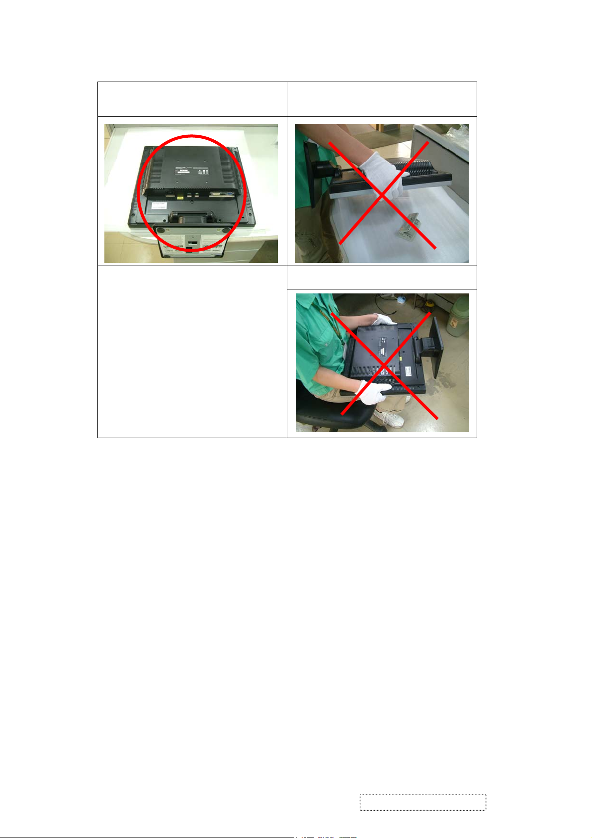
5. Handling and Placing Methods
Correct Methods: Incorrect Methods:
Only touch the metal frame of the LCD panel
or the front cover of the monitor. Do not touch
the surface of the polarizer.
Take out the monitor with cushions Taking out the monitor by grasping the LCD
Surface of the LCD panel is pressed by fingers
and that may cause ”Mura”.
panel. That may cause ”Mura”
ViewSonic Corporation Confidential
3
-
Do Not Copy VA905
Place the monitor on a clean and soft foam
pad.
Placing the monitor on foreign objects. That
could scratch the surface of the panel or cause
“Mura”.
The panel is placed facedown on the lap. That
may cause “Mura”.
ViewSonic Corporation Confidential
4
-
Do Not Copy VA905
2. Specification
1. General Requirements
General Specifications
Test Resolution & Frequency “1280 x 1024” @ 60Hz
Test Image Size Full Size
Contrast and Brightness Controls Factory Default:
Contrast = 70%, Brightness = 100%
2. Signal Interface
Video Interface
Analog Input Connector DB-15 (Analog)
Digital Input Connector DVI-D (Digital)
Default Input Connector Defaults to the first detected input
Video Cable Connector DB-15 Pin out Compliant DDC 1/2B.
Video Signals
Video Impedance 75 Ohms (Analog), 100 Ohms (Digital)
Exclusions Not compatible with interlaced video.
3. Power
Power Supply
Input Voltage Range 90 to 264 VAC
Power Dissipation 40 WATTS (TYP)
4. Electrical Requirements
Horizontal / Vertical Frequency
Horizontal Frequency 30 – 82 kHz
Vertical Refresh Rate 50 – 85 HZ
Maximum Pixel Clock 135 MHz
Primary Preset “1280 x 1024” @ 60Hz
Look up table timing
<<Analog>>
1. 640 x 350 @ 70Hz, 31.5kHz
2. 640 x 480 @ 60Hz, 31.5kHz
3. 640 x 480 @ 67Hz, 35.0kHz
4. 640 x 480 @ 75Hz, 37.5kHz
5. 640 x 480 @ 72Hz, 37.9kHz
6. 640 x 480 @ 85Hz, 43.27kHz
7. 720 x 400 @ 70Hz, 31.5kHz
8. 800 x 600 @ 56Hz, 35.1kHz
9. 800 x 600 @ 60Hz, 37.9kHz
10. 800 x 600 @ 75Hz, 46.9kHz
11. 800 x 600 @ 72Hz, 48.1kHz
12. 800 x 600 @ 85Hz, 53.7kHz
13. 832 x 624 @ 75Hz, 49.7kHz
14. 1024 x 768 @ 60Hz, 48.4kHz
15. 1024 x 768 @ 70Hz, 56.5kHz
16. 1024 x 768 @ 72Hz, 58.1kHz
17. 1024 x 768 @ 75Hz, 60.0kHz
18. 1024 x 768 @ 85Hz, 68.67kHz
19. 1280 x 1024 @ 60Hz, 63.4kHz
20. 1280 x 1024 @ 75Hz, 79.97kHz
Video RGB (Analog) Separate Sync
2. TMDS (Digital)
<<Digital>>
640 x 350 @ 70Hz, 31.5kHz
640 x 400 @ 60Hz, 31.5kHz
640 x 480 @ 60Hz, 31.5kHz
640 x 480 @ 75Hz, 37.5kHz
640 x 480 @ 72Hz, 37.9kHz
640 x 480 @ 85Hz, 43.27kHz
720 x 400 @ 70Hz, 31.5kHz
800 x 600 @ 56Hz, 35.1kHz
800 x 600 @ 60Hz, 37.9kHz
800 x 600 @ 75Hz, 46.9kHz
800 x 600 @ 72Hz, 48.1kHz
800 x 600 @ 85Hz, 53.7kHz
1024 x 768 @ 60Hz, 48.4kHz
1024 x 768 @ 70Hz, 56.5kHz
1024 x 768 @ 72Hz, 58.1kHz
1024 x 768 @ 75Hz, 60.0kHz
1024 x 768 @ 85Hz, 68.67kHz
1280 x 1024 @ 60Hz, 63.4kHz
ViewSonic Corporation Confidential
5
-
Do Not Copy VA905

Changing Modes
Maximum Mode Change Blank Time for
image stability. Note:
1) Excluding “Auto Adjust” time
2) Under DOS mode (640 x 350, 720 x 400 &
640 x 400), there is no “Auto Adjust” feature.
3) The monitor needs to do “Auto Adjust” the
first time a new mode is detected.
5. Audio
Speaker Specification
Line input connection 3.5 mm stereo jack
Line input signal 1.0Vrms
Line input impedance 10K ohm
Maximum power output (Electric) 2 W @ < 15 % DISTORTION
Signal to Noise Ratio 72 dB
Frequency response 400 Hz – 20 kHz
Distortion <15 % THD (@1kHz),
6. LCD Panel
Panel Characteristics
Panel Type HSD190ME12-A02
Type “TFT ACTIVE MATRIX
Active Size 376.32 (H) x 301.056 (V)
Pixel Arrangement RGB Vertical Stripe
Pixel Pitch 0.294 mm
# of Backlights 4 CCFL edge-light (2 top / 2 bottom)
Backlight Life 40,000 Hours (minimum)
Panel Performance
Luminance –
Condition:
CT = 6500K, Contrast = Max,
Brightness = Max
Brightness Uniformity ∆L5=Max 1.3 ∆L5= Maximum Luminance/
Contrast Ratio 500:1 (typ.), 350:1 (minimum)
Color Depth 16.2M colors (RGB 6-bit data+FRC data)
Viewing Angle (Horizontal) 140 degrees @ CR>10
Viewing Angle (Vertical) 130 degrees @ CR>10
Response Time
10%-90% @ Ta=25°C
Note: The 2nd source of LCD panel is “HSD190ME12-A04”
Under 5 seconds (Maximum)
1 seconds (Typ.) for recognized timings
1-2 seconds (Typ.) for unrecognized timing
250 cd/m2 (typ. after 30-minute warm-up)
200 cd/m2 (minimum after 30-minute
warm-up)
Minimum Luminance
12 ms (typ.)
20 ms (maximum)
ViewSonic Corporation Confidential
6
-
Do Not Copy VA905
7. Mechanical
Dimensions
Width 418 mm
Height 412.5 mm
Depth 178.5 mm
Monitor Weight 5.6kg / 12.32 lbs
Ergonomics
Tilt Up 25 DEGREES MINIMUM
Tilt Down -0 degrees
Package Specifications
Width 490 mm
Height 525 mm
Depth 145 mm
Gross Weight 7.1kg (15.6 lb)
8. Environmental
Environmental Conditions
Operating Temperature 0°C to +40°C
Storage Temperature -20°C to +60°C
Operating Relative Humidity 20% to 80% RH Non-Condensing
Storage Relative Humidity 5% to 90% RH Non-Condensing
Operating Altitude 0 to +3,000 meters
Storage Altitude 0 to +12,000 meters
ViewSonic Corporation Confidential
7
-
Do Not Copy VA905
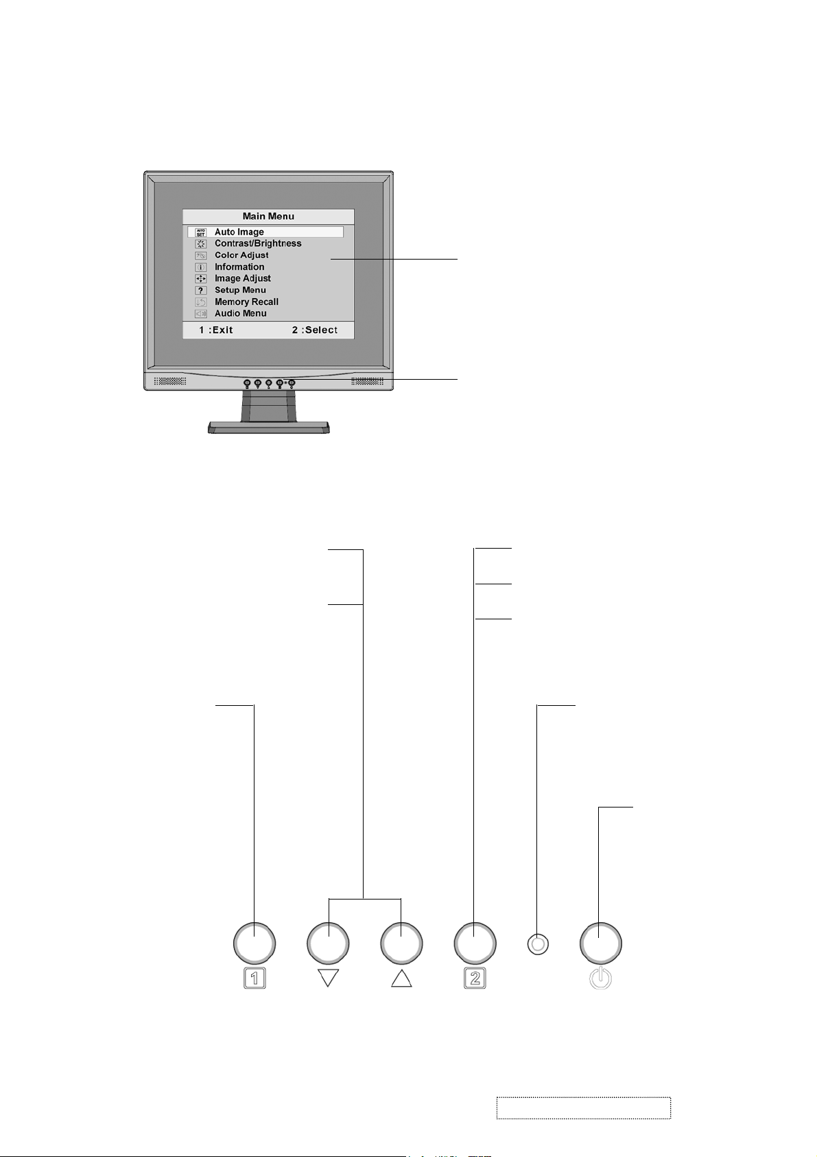
3. Front Panel Function Control Description
1. Control Location
Main Menu
with OSD controls
Front Control Panel
shown below in detail
Scrolls through menu options
and adjusts the displayed
Also a shortcut to display the
Contrast adjustment control
Displays the
Main Menu or
exits the
control screen
and saves
adjustments.
control.
screen.
Displays the control screen for the
highlighted control.
Also toggles between two controls
on some screens.
Also a shortcut to Auto Image
Adjust.
Power light
Green = ON
Orange = Power Saving
Standby Power
On/Off
ViewSonic Corporation Confidential
8
-
Do Not Copy VA905
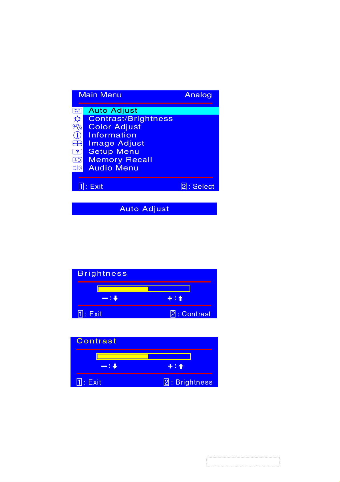
2. OSD Menu Controls
Select the menu items shown below by using the up [▲] and down [▼] buttons.
Main Menu:
Auto Adjust:
To automatically adjust H./V. Position, Phase adjust and Clock adjust.
REMARK: There may need manual adjustment of “ phase " for optimized
performance for various VGA tolerance.
ViewSonic Corporation Confidential
9
-
Do Not Copy VA905

Contrast /Brightness:
To adjust the Contrast of the video and the backlight currency.
.
Color Adjust:
To select the color temperature 6500°K, 9300°K , 5400°K or user settings.
ViewSonic Corporation Confidential
10
-
Do Not Copy VA905

Information:
To display the data about Horizontal / Vertical frequency, Pixel clock,
Resolution , Model number and Serial No. of the monitor.
ViewSonic Corporation Confidential
11
-
Do Not Copy VA905

Image Adjust:
H./V. Position: To adjust the horizontal and vertical position of the video.
Hsize: To adjust the horizontal pixel clock of the video.
Fine Tune: To adjust the delay time of data and clock.
Sharpness: To select the picture sharpness of display.
ViewSonic Corporation Confidential
12
-
Do Not Copy VA905
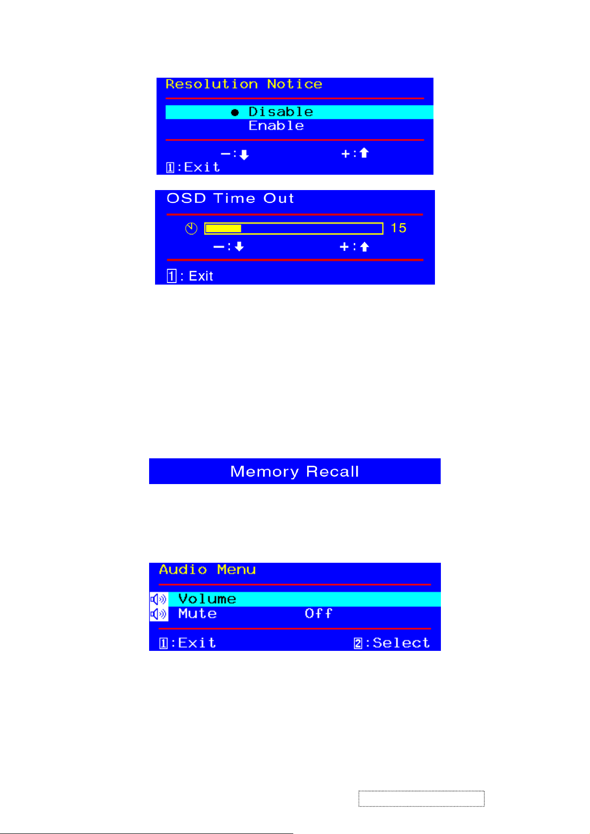
Setup Menu::
Language Select: To select one of eight languages.
(English, French, German, Italian, Spanish, Finnish,
Japanese, Traditional Chinese, and Simplified Chinese)
Resolution Notifier: Enable : OSD will Notifier the best picture quality resolution
change
OSD Position: To set OSD position.
OSD Timeout: To set the displaying time of OSD.
the resolution to 1280x1024
INPUT SELECT:TO SELECT DSUB ANALOG OR DVID DIGITAL INPUT
Memory Recall:
Restore default settings of Clock, H./V. Position, Phase, Contrast, Brightness, Color
temperature, OSD position, OSD timeout and Sharpness, Volume.
Audio Menu:
Volume: To adjust the output of speaker or earphone.
Mute: To set or reset the mute function.
ViewSonic Corporation Confidential
13
-
Do Not Copy VA905
3. Hot Keys for Function Controls
Buttons: Functions:
[Up] + [Down] arrows recall Contrast or Brightness while in the Contrast
[2] + [Up] volume mute on or off when OSD is not on.
[2] Input toggle (Analog or Digital)
[2] + [Up] + [Down] White Balance. White Balance should set the screen
[2] + [Down] (hold for 10 seconds) Power Lock (Unlock). User won’t be able to turn off
[2] + [Up] (hold for 10 seconds) OSD Lock (Unlock). It will lock all functions.
[Up] + [Down] + [Power On] with signal
(hold for 3 seconds)
[Up] + [Down] + [Power On]
without signal
(hold for 3 seconds)
or Brightness adjustment, or recall both of Contrast
and Brightness when the OSD is not on.
on the pure black and white pattern with
640*480@60Hz resolution.
the monitor.
Inter FACTORY mode adj white balance.
Burn in Mode.
ViewSonic Corporation Confidential
14
-
Do Not Copy VA905

4. Circuit Description
1. Power supply (DC/DC Converter)
This brick convert is the 110-220AC input voltage to 12V AND 5V output for invert use and panel
use and system controller use.
It consists of a PWM IC (FP5001, I804), flywheel diode (MS2 2,D812), buck choke (L812) and
capacitor C817.
5V Out put at 5,6 pin
VCC 12V In put at L801,L812 pin
2. Scaling controller
The ADC is to convert RGB analog signal to digital signal that scaling chip can acknowledge.
The HSYNC input receives a logic signal and provides the frequency reference for pixel clock
generation.
The scaling IC is to converts the input signal ranging from VGA to SXGA into SXGA resolution that panel
can acknowledge.
GENERAL DESCRIPTION
The I108TSU56AK is a high performance, and fully integrated graphics processing IC solution for
LCD monitors with resolutions up to SXGA. It is configured with an integrated triple-ADC/PLL, a
high quality scaling engine, an on-screen display controller, a built-in output clock generator, an
integrated DVI receiver, and LVDS display interface. To further reduce system costs, the
TSU56AK also integrates intelligent power management.
3. MTV312M64
The I106 MTV312M micro-controller is an 8051 CPU core embedded device especially tailored
for CRT/LCD Monitor applications. It includes an 8051 CPU core, 1024-byte SRAM, 14 built-in
PWM DACs, VESA DDC interface, 4- channel A/D converter, and a 64K-byte internal pro gram
Flash-ROM.
A “CMOS output pin” means it can sink and drive at least 4mA current. It is not recommended to
use
Such pin as input function. A “open drain pin” means it can sink at least 4mA current but only
drive 10~20uA to VDD. It can be used as input or output function and needs an external pull up
resistor
ViewSonic Corporation Confidential
15
-
Do Not Copy VA905
5. Adjustment Procedure
1. Function Test
1.1 Product
- 19” LCD Monitor
1.2 Test Equipment
- Color Video Signal & Pattern (or PC with SXGA resolution and a sound card)
1.3 Test Condition
Before function test and alignment, each LCD Monitor should be run-in and warmed up for at least
30 minutes with the following conditions:
(a) In room temperature,
(b) With full-white screen, RGB, and Black
(c) With cycled display modes,
640*480 (H=43.27kHz, V=85Hz)
800*600 (H=53.7kHz, V=85Hz)
1024*768 (H=68.67kHz, V=85Hz)
1280*1024 (H=79.97kHz, V=75Hz)
1.4 Test Display Modes & Pattern
1.4.1 Compatible Modes
Analog Digital
1. 640 x 350 @ 70Hz, 31.5kHz
2. 640 x 480 @ 60Hz, 31.5kHz
3. 640 x 480 @ 67Hz, 35.0kHz
4. 640 x 480 @ 75Hz, 37.5kHz
5. 640 x 480 @ 72Hz, 37.9kHz
6. 640 x 480 @ 85Hz, 43.27kHz
7. 720 x 400 @ 70Hz, 31.5kHz
8. 800 x 600 @ 56Hz, 35.1kHz
9. 800 x 600 @ 60Hz, 37.9kHz
10. 800 x 600 @ 75Hz, 46.9kHz
11. 800 x 600 @ 72Hz, 48.1kHz
12. 800 x 600 @ 85Hz, 53.7kHz
13. 832 x 624 @ 75Hz, 49.7kHz
14. 1024 x 768 @ 60Hz, 48.4kHz
15. 1024 x 768 @ 70Hz, 56.5kHz
16. 1024 x 768 @ 72Hz, 58.1kHz
640 x 350 @ 70Hz, 31.5kHz
640 x 400 @ 60Hz, 31.5kHz
640 x 480 @ 60Hz, 31.5kHz
640 x 480 @ 75Hz, 37.5kHz
640 x 480 @ 72Hz, 37.9kHz
640 x 480 @ 85Hz, 43.27kHz
720 x 400 @ 70Hz, 31.5kHz
800 x 600 @ 56Hz, 35.1kHz
800 x 600 @ 60Hz, 37.9kHz
800 x 600 @ 75Hz, 46.9kHz
800 x 600 @ 72Hz, 48.1kHz
800 x 600 @ 85Hz, 53.7kHz
1024 x 768 @ 60Hz, 48.4kHz
1024 x 768 @ 70Hz, 56.5kHz
1024 x 768 @ 72Hz, 58.1kHz
1024 x 768 @ 75Hz, 60.0kHz
ViewSonic Corporation Confidential
16
-
Do Not Copy VA905
17. 1024 x 768 @ 75Hz, 60.0kHz
1024 x 768 @ 85Hz, 68.67kHz
18. 1024 x 768 @ 85Hz, 68.67kHz
19. 1280 x 1024 @ 60Hz, 63.4kHz
20. 1280 x 1024 @ 75Hz, 79.97kHz
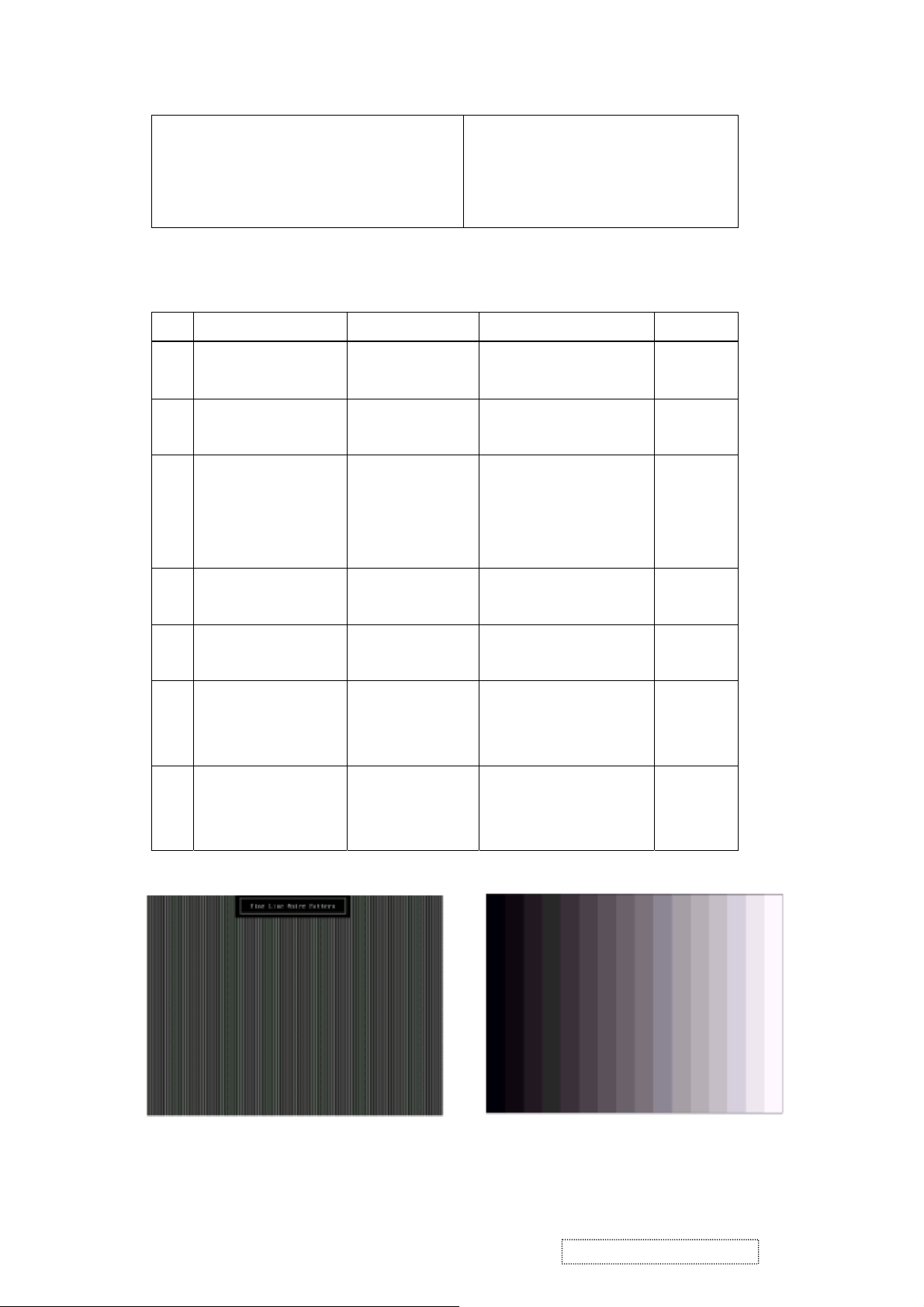
1.4.2 Function Test Display Pattern
Item Test Content Pattern Specification Remark
1 Frequency & Tracking Fine Line Moire Eliminate visual wavy
2 Contrast/Brightness 16 Gray Scale 16 gray levels should be
3 Boundary Horizontal &
4 RGB Color
Vertical Thickness
RGB Color
1280 x 1024 @ 60Hz, 63.4kHz
noise.
distinguishable.
Horizontal and Vertical
position of video should be
adjustable to be within the
screen frame.
Contrast of each R, G, B,
Figure 1
Figure 2
Figure 3
Figure 4, 5,
Performance
5 Screen Uniformity &
Flicker
6 Dead Pixel/Line White Screen &
7 White Balance White & Black
Intensities
Full White Should be compliant with
Dark Screen
Pattern
color should be normal.
the spec.
The numbers of dead
pixels should be compliant
with the spec.
The screen must have the
pure white and black
pattern, no other color.
6
Figure 7
Figure 7, 8
Figure 9
Fine Line Morie Pattern (Figure1) Gray Scale Pattern (Figure2)
ViewSonic Corporation Confidential
17
-
Do Not Copy VA905
 Loading...