

Page 1

Service Manual
ViewSonic VA903b-3
VA903m-3
Model No. VS11372
19” Color TFT LCD Display
(VA903b-1_ VA903m-1_SM Rev.
1a Sep. 2006)
ViewSonic 381 Brea Canyon Road, Walnut, California 91789 USA - (800) 888-8583
Page 2
Copyright
Copyright © 2006 by ViewSonic Corporation. All rights reserved. No part of this publication
may be reproduced, transmitted, transcribed, stored in a retrieval system, or translated into any
language or computer language, in any form or by any means, electronic, mechanical, magnetic,
optical, chemical, manual or otherwise, without the prior written permission of ViewSonic
Corporation.
Disclaimer
ViewSonic makes no representations or warranties, either expressed or implied, with respect to
the contents hereof and specifically disclaims any warranty of merchantability or fitness for any
particular purpose. Further, ViewSonic reserves the right to revise this publication and to make
changes from time to time in the contents hereof without obligation of ViewSonic to notify any
person of such revision or changes.
Trademarks
Optiquest is a registered trademark of ViewSonic Corporation.
ViewSonic is a registered trademark of ViewSonic Corporation.
All other trademarks used within this document are the property of their respective owners.
Revision History
Revision SM Editing Date ECR Number Description of Changes Editor
1a 09/08/2006 Initial Release Jamie Chang
ViewSonic Corporation Confidential - Do Not Copy VA903b-1_ VA903m-1
i
Page 3
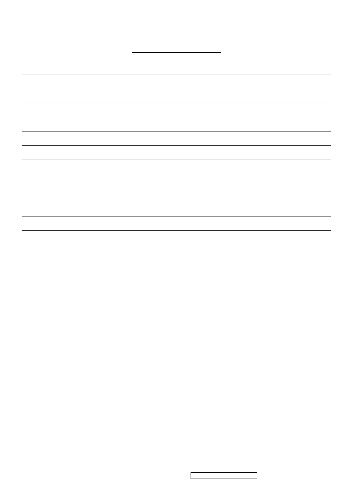
TABLE OF CONTENTS
1. Precautions and Safety Notices 1
2. Specification 4
3. Front Panel Function Control Description 13
4. Circuit Description 16
5. Adjustment Procedure 23
6. Troubleshooting Flow Chart 47
7. Recommended Spare Parts List 55
8. Exploded Diagram and Exploded Parts List 60
9. Block Diagram 65
10. Schematic Diagrams 66
11. PCB Layout Diagrams 72
ViewSonic Corporation Confidential - Do Not Copy VA903b-1_ VA903m-1
ii
Page 4

1. Precautions and Safety Notices
1. Please carefully read this manual before operating the device and keep it available for future reference.
2. To avoid the danger of the monitor falling and thereby possibly causing injury and/or serious damage to the
monitor itself, do not place it on unstable cars or desks. Be careful to avoid placing any stress on the LCD screen
during handling.
3. Do not place this monitor in areas that are wet or where water or other liquids may come in contact with it, such as
bathrooms, kitchens, wet floors, near washing machines or by swimming pools.
4. Remove the power plug from the electrical socket before cleaning. No water-containing cleaning agent should be
used to clean the screen, but only cleaning agents formulated specifically for cleaning LCD screens. Do not put any
liquid cleaning agent directly on the screen, but put it on a soft cloth first and then gently apply the cloth to the
screen.
5. In order to guarantee reliable operation and adequate heat dissipation, do not cover or block vent holes on the
monitor. Do not put the monitor close to heat sources. Do not place the monitor on furniture such as a bookshelf,
unless sufficient ventilation is available.
6. A 3-pin grounding plug is provided for this monitor. In order to guarantee normal operation and safety of this unit,
this plug should be used with a matching grounded power socket.
7. Please follow all warnings and instructions that accompany the monitor.
8. Please pay special attention to power supply overloads, as electrical shock or fire may occur.
9. Do not place anything on the power cord. Do not hang the power cord over an area where people or objects may
pass.
10. In case the monitor is not be used for an extended period, turn off power to avoid the possibility of short circuits
caused by lightning.
11. In order to avoid electrical shock or fire risks, do not insert any object through any openings in the monitor’s
enclosure. Do not allow any liquid to come in contact with the monitor.
12. In case of any abnormal noise or odor caused by incorrect operation, turn off power immediately and contact a
professional technician. Do not attempt to repair this monitor by yourself, as electrical shock may occur when
opening the back cover or accessing internal components.
13. If any of the following conditions occurs, turn off power and contact a repair service provider:
1) the power cord is damaged or worn;
2) liquid has gotten into the monitor, or the monitor has experienced immersion or wetting;
3) the monitor has fallen;
4) the monitor’s performance shows obvious changes;
5) the monitor fails to work normally when correct procedures are followed. In that case, please make any
adjustments in accordance with instructions supplied with the monitor; do not attempt any changes to
established procedures, as further damage may occur, making successful repair of the monitor more difficult.
14. In case parts need to be replaced, you must use identical parts or those supplied by our certified manufacturers. Any
other parts used without our authorization may result in electrical shock or fire risk.
ViewSonic Corporation Confidential - Do Not Copy VA903b-1_ VA903m-1
1
Page 5
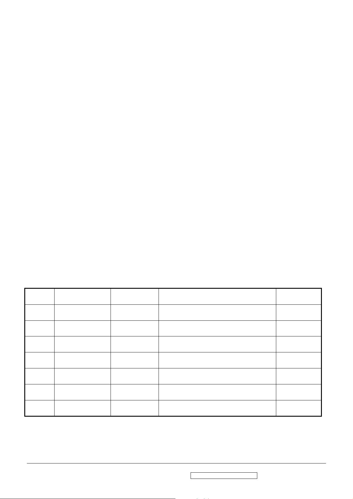
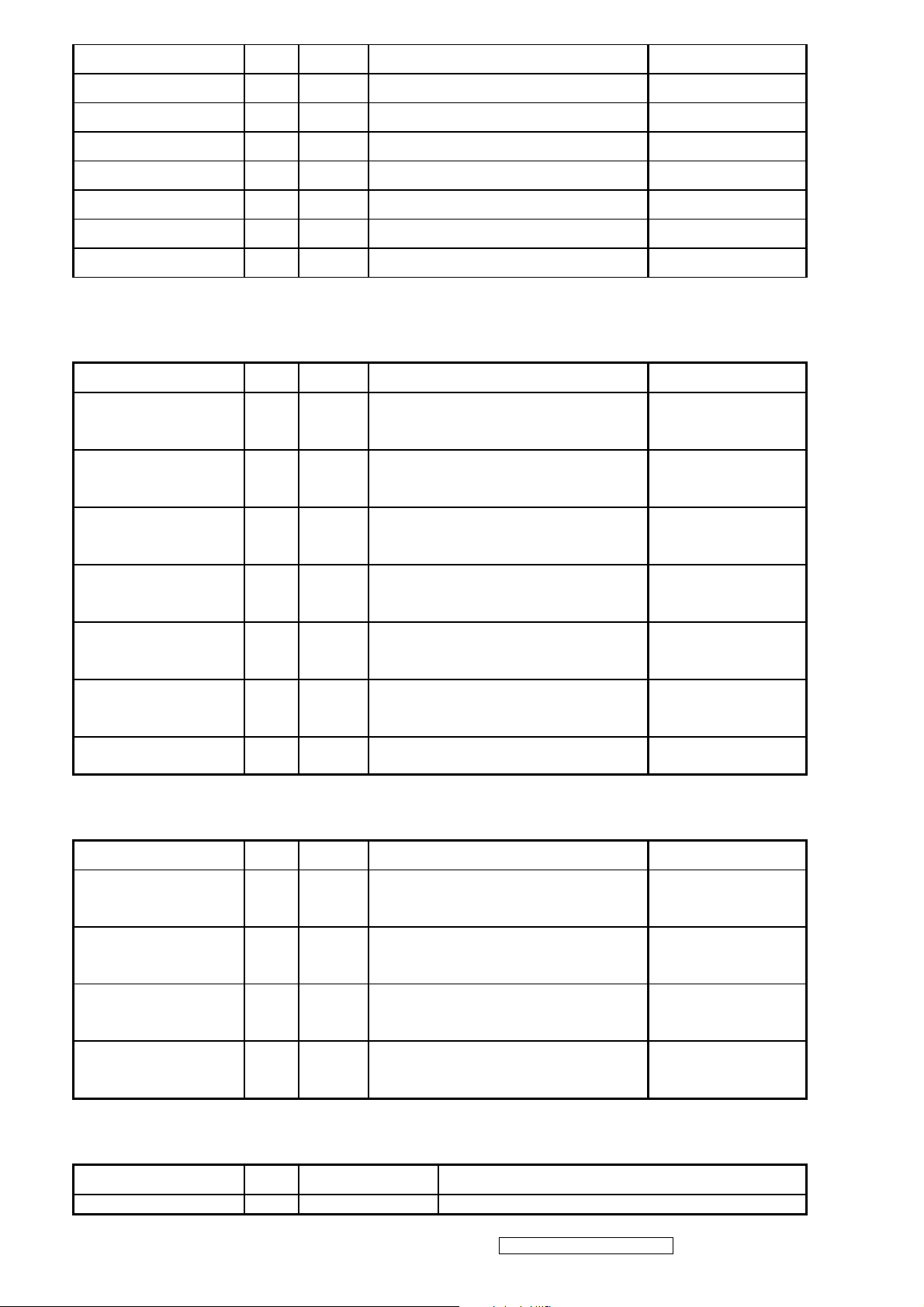
Handing and Placing methods
Correct methods Incorrect methods
Only touch the metal frame of the LCD panel or the
front cover of the monitor, DO not touch the surface
of the POL
Surface of the LCD panel is pressed by fingers and that
may cause”mura”
Take out the monitor with cushions Taking out the monitor by grasping the LCD panel, that
May cause”mura”
ViewSonic Corporation Confidential - Do Not Copy VA903b-1_ VA903m-1
2
Page 6
Place the monitor on a clean and soft foam pad Placing the monitor on a foreign objects, that could
scratch The surface of the "Panel" or cause "mura"
The panel is placed facedown the lap,that may cause
"mura"
ViewSonic Corporation Confidential - Do Not Copy VA903b-1_ VA903m-1
3
Page 7
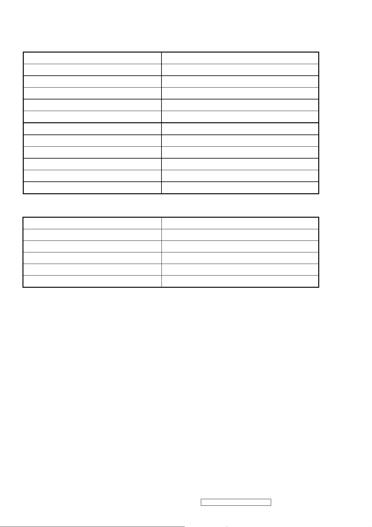
2. Specification
INTRODUCTION
FEATURES VA903b-3 / VA903m-3
Size 19 “
Luminance (Typ)
Contrast Ratio (Typ) 700 :1
1st TFT LCD panel
Input Signal
Sync Compatibility
Compatibility
Power Voltage AC 100-240V, 50/60Hz Yes
Colors 16.2 M colors (6+2bit panel)
Response Time (Typ) 8 ms
Viewing Angle (H/V) 150 ° / 135 °
Recommend resolution 1280 x 1024 @60Hz
Analog (75ohms, 1.0 Vp-p) Yes
Digital (DVI-D) No
Separate Sync Yes
Composite Sync No
Sync on Green No
PC Yes
Power Mac Yes
TV Box (NextVision 6) Yes
On Mode(Max / Typ) Under 36 W in max/32W IN TYP
300 cd/㎡
Power Consumption
Active Off Mode (Max)
Tilt ( -5 ° - 22.5 °)
Swivel No
Ergonomics
Pivot No
Height Adjust No
OSD Control [ 1 ] [ 2 ] [ ][▲] [▼] Yes
Physical (W x H x D) 416*429*210mm
Dimension
Package (W x H x D) 485*503*163mm
Physical (Net Weight) 4.6Kg / 10.12 lb
Weight
Package (Gross Weight) 5.8Kg/ 12.76 lb
Temperature (℉/℃) 32℉~104℉ / 0℃~40℃
Operating Condition
Humidity (%) 20 % - 90 %
Temperature (℉/℃) -4℉~140℉ / -20℃~60℃
Storage Condition
Humidity (%) 5 % - 90 %
Saving mode< 2W
Off mode <1 W
Yes
UL/cUL, FCC-B,TUV-S, CB, CE, TUV/GS, TUV/ERGO, TCO03, BSMI,
Regulation
CCC, (PSB), (C-TICK), GOST-R/HYGIENIC, SASO, WEEE, RoHS,
ENERGY STAR,
ViewSonic Corporation Confidential - Do Not Copy VA903b-1_ VA903m-1
4
Page 8
Product definition and specification
Product Name VA903b-3 / VA903m-3
Model Number VS11372
M model for America
E model for Europe
G model for China
Region
OSD Languages
TFT LCD Panel and Model # HSD, Model # :190ME13-A16/A10
Scalar RTD, Model # : RTD2023L
Input Signal Analog
Sync Compatibility Separate
Audio
Adapter No
Power Cable Refer to Appendix D
Analog Cable (1.8 m, color : black), with PC 2001 and
Hot Plug Detect &DDC
P model for Asia
A model for Australia
S model for Singapore
K model for Korea
U model for UK
English, French, German, Italian, Spanish,
Finnish, Japanese, Traditional Chinese,
Simplified Chinese
1 W @ < 15% distortion (For VA903m-3 only)
Yes
Audio Cable (1.8m, Color: black) with PC 2001 Yes (For VA903m-3 only)
ViewSonic CD Wizard
ViewSonic Quick Start Guide
Screen Protector Mylar Yes
Hi Pot label Yes
QA pass label For G model only
Hg Warning label Yes
Warranty Sticker For G model only
Warranty Card For G model only
Carton Sticker For G model only
PE bag of Carton For G model only
Arabic, English, Finnish, Spanish, German,
Italian, Swedish, Polish, Korean, Portuguese,
Russian, French, Simplified Chinese,
Traditional Chinese, Hungary, Czech, Turkish
ViewSonic Corporation Confidential - Do Not Copy VA903b-1_ VA903m-1
5
Page 9
GENERAL specification
Test Resolution & Frequency 1280 x 1024 @ 60Hz
Test Image Size Full Size
Contrast and Brightness Controls
Factory Default:
Contrast = 70%, Brightness = 100%
VIDEO INTERFACE
Analog Input Connector DB-15 (Analog), refer the appendix A
Default Input Connector Defaults to the first detected input
Equal to twice the weight of the monitor for five
Video Cable Strain Relief
minutes
Video Cable Connector DB-15 Pin out Compliant DDC 2B
Video Signals Video RGB (Analog), Separate
Video Impedance 75 Ohms (Analog)
Maximum PC Video Signal 950 mV with no damage to monitor
Maximum Mac Video Signal 1250 mV with no damage to monitor
Sync Signals TTL
DDC 2B Compliant with Revision 1.3
Sync Compatibility Separate Sync
Video Compatibility
Shall be compatible with all PC type computers,
Macintosh computers, and after market video cards
640 x 350, 640 x 480, 720 x 400 (640 x 400), 800 x
Resolution Compatibility
600, 832 x 624, 1024 x 768, 1152 x 864, 1280 x 1024
Exclusions Not compatible with interlaced video
POWER SUPPLY
Internal Power Supply Part Number: PI-SB03/
Input Voltage Range
Input Frequency Range
Short Circuit Protection
Over Current Protection
Leakage Current
Efficiency
Fuse
Power Dissipation
Max Input AC Current
Inrush Current (Cold Start)
100 - 240VA C
50/ 60 Hertz
OUTPUT CAN BE SHORTED WITHOUT DAMAGE
6.0 A TYPICAL AT 5.0 VDC
1.0 MA (MAX) AT 264 VAC / 60HZ
80 % TYPICAL AT 115 VAC FULL LOAD
INTERNAL AND NOT USER REPLACEABLE
32 WATTS (TYP)
1.2 ARMS @ 90VAC, 0.8 ARMS @180VAC
30 A @ 90VAC, 60 A(MAX) @ 264 VA C
SHALL START AND FUNCTION PROPERLY WHEN
Power Supply Cold Start
UNDER FULL LOAD, WITH ALL COMBINATIONS OF
INPUT VOLTAGE, INPUT FREQUENCY, AND
OPERATING TEMPERATURE
ViewSonic Corporation Confidential - Do Not Copy VA903b-1_ VA903m-1
6
Page 10
Power Supply Transient Immunity
Power Supply Line Surge Immunity
SHALL BE ABLE TO WITHSTAND AN ANSI/IEEE
C62.41-1980 6000V 200 AMPERE RING WAVE
TRANSIENT TEST WITH NO DAMAGE
Shall be able to withstand 1.5 times nominal line
voltage for one cycle with no damage
Shall be able to function properly, without reset or
Power Supply Missing Cycle Immunity
Power Supply Acoustics
US Type Power Cable
Power Saving Operation (Method) VESA DPMS Signaling
Power Consumption
Recovery Time On Mode = N/A, Active Off < 3 sec
ELECTRICAL REQUIREMENTS
Horizontal / Vertical Frequency
visible screen artifacts, when ½ cycle of AC power is
randomly missing at nominal input
The power supply shall not produce audible noise that
would be detectable by the user. Audible shall define
to be in compliance with ISO 7779 (DIN
EN27779:1991) Noise measurements of machines
acoustics. Power Switch noise shall not be considered
Length = 1.8m. Connects to AC/DC Power Color =
Black
ON Mode < 36 W (max)
pOWER sAVING < 2W ,OFF < 1W
Horizontal Frequency
Vertical Refresh Rate
Maximum Pixel Clock 135 MHz
Sync Polarity Independent of sync polarity.
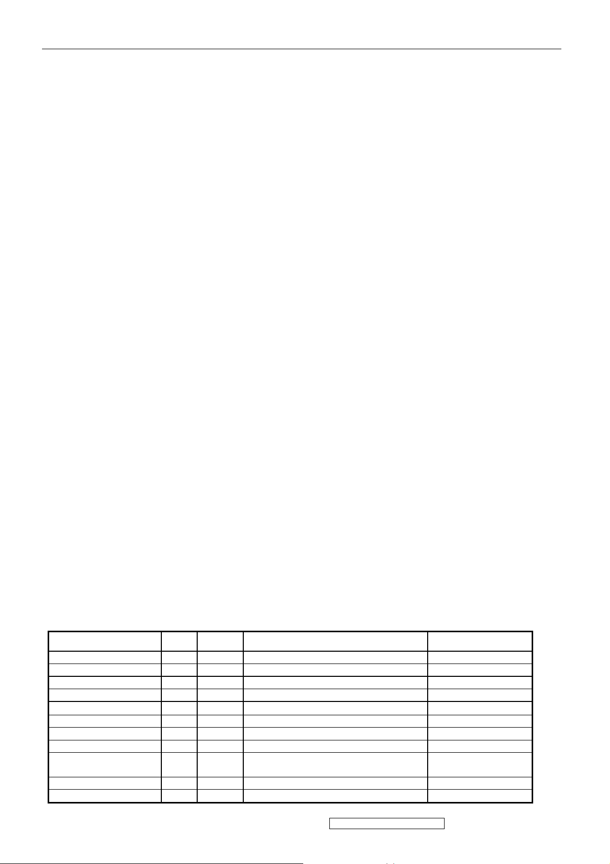
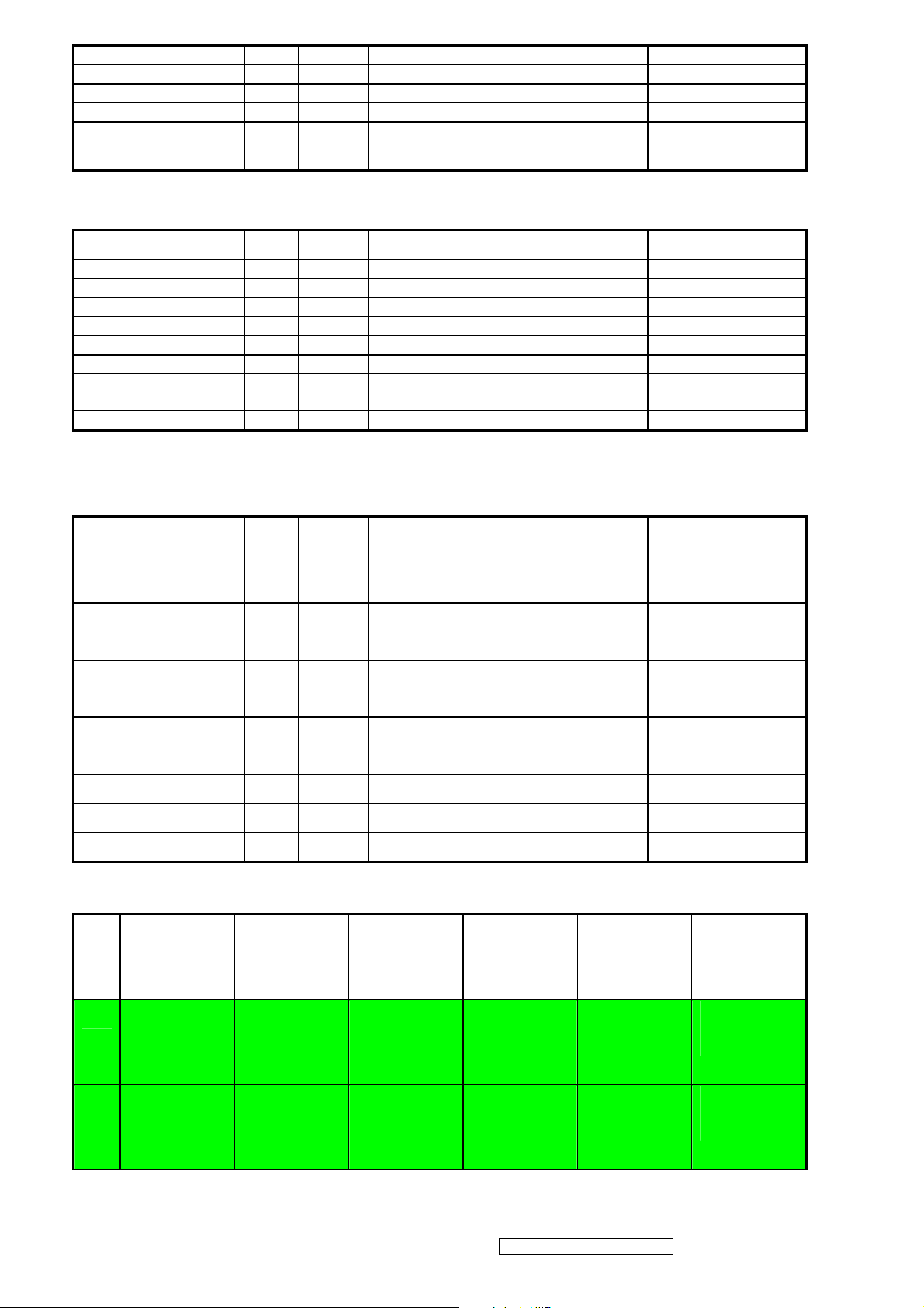
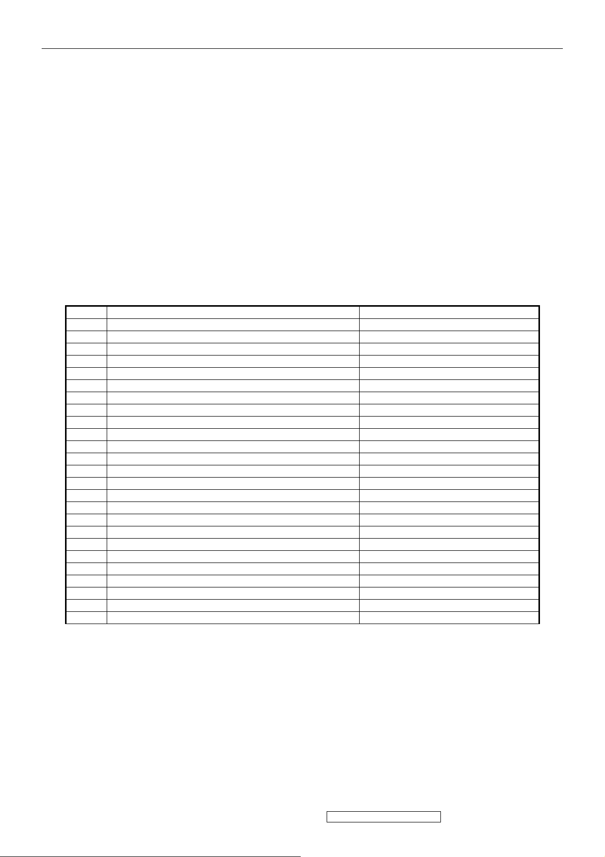
Timing Table
Item Timing Analog
1 640 x 350 @ 70Hz, 31.5kHz Yes
2 640 x 480 @ 50Hz, 24.68KHZ Yes
3 640 x 480 @ 60Hz, 31.5kHz Yes
4 MAC 640 x 480 @ 67Hz, 35.0kHz Yes
5 640 x 480 @ 72Hz, 37.9kHz Yes
6 640 x 480 @ 75Hz, 37.5kHz Yes
7 640 x 480 @ 85Hz, 43.27kHz Yes
8 720 x 400 @ 70Hz, 31.5kHz Yes
9 800 x 600 @ 56Hz, 35.1kHz Yes
30 – 82 kHz
50 – 85 Hz.
10 800 x 600 @ 60Hz, 37.9kHz Yes
11 800 x 600 @ 72Hz, 48.1kHz Yes
ViewSonic Corporation Confidential - Do Not Copy VA903b-1_ VA903m-1
7
Page 11
12 800 x 600 @ 75Hz, 46.9kHz Yes
13 800 x 600 @ 85Hz, 53.7kHz Yes
14 MAC 832 x 624 @ 75Hz, 49.7kHz Yes
15 1024 x 768 @ 60Hz, 48.4kHz Yes
16 1024 x 768 @ 70Hz, 56.5kHz Yes
17 1024 x 768 @ 72Hz, 58.1kHz Yes
18 1024 x 768 @ 75Hz, 60.0kHz Yes
19 1024 x 768 @ 85Hz, 68.67KHZ Yes
20 1152 x 864 @ 75Hz, 67.5KHZ Yes
21 MAC 1152x870@75HZ, 68.68KHZ Yes
22 1280 x 960 @ 60Hz, 44.93KHZ Yes
23 1280 x 960 @75Hz, 56.25KHZ Yes
24 1280 x 1024 @ 60Hz, 63.98KHZ Yes
25 1280 x 1024 @ 75Hz, 79.97KHZ Yes
*1. Tolerance ≧ ± 2kHz.
*2. Any timing not in the list, it should display as normal or show on “OUT OF RANGE” OSD message without
blanking.
*3. The image quality of 85Hz mode might be worse than 75Hz.
Primary Presets
1280 x 1024 @ 60Hz
User Presets
Number of User Presets (recognized timings) Available: 10 presets total in FIFO configuration
Changing Modes
● Maximum Mode Change Blank Time for image stability : 3 seconds (Max), excluding “Auto
Image Adjust” time
● Under DOS mode (640 x 350, 720 x 400 & 640 x 400), it should recall factory setting when
execute “Auto Adjust”
● The monitor needs to do “Auto Image Adjust” the first time a new mode is detected
(See section “0-Touch™ Function Actions”)
● The monitor needs to do “Auto Adjust” the first time a new mode is detected
(See section “0-Touch™ Function Actions”)
ViewSonic Corporation Confidential - Do Not Copy VA903b-1_ VA903m-1
8
Page 12
AUDIO INTERFACE (SPEAKER SPECIFICATION) (For VA903m-3 only)
Line input connection
3.5 mm stereo jack
Line input signal 1.0Vrms
Line input impedance >10 kOhm
Maximum power output (Electric)
1 W @ <15% DISTORTION
Signal to Noise Ratio 50 dB
Frequency response 200 Hz – 20 Khz
Distortion
<15% THD (@1kHz)
There should be no audible vibration with volume at
Vibration
100%. (Input signal within 1.0 Vrms)
There should be no affect on the screen image
Screen image
stability under any conditions
Connector PC99 requirement Audio in
Lime Green pantone # 577C
Cable type / length 3.5mm stereo cable / 1.8m length
NOTE: THERE IS NO GUARANTEE <1 W POWER
Audio DPMS
CONSUMPTION IN ACTIVE OFF MODE, WHEN THE
AUDIO CABLE IS CONNECTED
TFT LCD PANEL
1st Panel Source
Type
HSD 190ME13-A16/A10
TN, LVDS
Active Size 376.32 mm (H) x 301.056mm (V)
Pixel Arrangement RGB Vertical Stripe
Pixel Pitch 0.294 mm
Glass Treatment
# of Backlights
Backlight Life
Luminance –Condition: CT = 6500 K
Contrast = Max, Brightness = Max
ANTI GLARE (HARD COATING 3H)
4 CCFL EDGE-LIGHT
50,000 HOURS (MAX) / 40,000 HOURS (MIN)
300 CD/M2 (TYP AFTER 30 MINUTE WARM UP)
240 CD/M2 (MIN AFTER 30 MINUTE WARM UP)
Brightness Uniformity 75 % (min)
Contrast Ratio 700 :1 (Typ), 450 :1 (Min)
Color Depth Vertical) 16.2 million colors (6+2 bit panel)
150 deg (Typ)@ CR>10
Viewing Angle (Horizontal)
160 deg (Typ)@ CR>5
135 deg (Typ) @ CR>10
Viewing Angle (Vertical)
150 deg (Typ)@ CR>5
Response Time
10%-90% @ Ta=25°C
8 ms (Tr= 2 ms, Tf = 6 ms) (Typ)
12 ms (Tr= 4 ms, Tf = 8 ms) (max)
Panel Defects Please see Panel Quality Specifications.
ViewSonic Corporation Confidential - Do Not Copy VA903b-1_ VA903m-1
9
Page 13
IMAGE PERFORMANCE
Display Size
Horizontal Display Size, Primary Preset
Vertical Display Size, Primary Preset
Luminance
Lv (Max) –Condition:
Brightness / Contrast = 100%
CCT = USER COLOR (R/G/B=100%)
Lv (6500Kf) –Condition:
Brightness / Contrast = Default
Color Temperature = 6500K
Lv (sRGB) –Condition:
Brightness / Contrast = Default
CCT =sRGB
Lv (9300K) –Condition:
Brightness / Contrast = Default
CCT = 9300K
FULL SCREEN
FULL SCREEN
Lv (Max) = The Luminance requirement of section 4-6
“TFT LCD PANEL”
Lv (6500K) / Lv (Max) x 100% ≧ 85%
Lv (sRGB) / Lv (Max) x 100% ≧85%
Lv (9300K) / Lv (Max) x 100% > 70%
Lv (5400K) –Condition:
Brightness / Contrast = Default
CCT = 5400K
Lv (Brightness) –Condition:
Contrast = 100%
Lv (Contrast) –Condition:
Brightness = 100%
Contrast Ratio
CR(Max) –Condition:
Contrast / Brightness = 100%
CCT = USER COLOR (R/G/B=100%)
CR(6500K) –Condition:
Contrast / Brightness = 100%
CCT = 6500K
Lv (5400K) / Lv (Max) x 100% > 75%
Lv(Brightness=0%) / Lv(Brightness=100%) x 100% ≤ 55%
Lv(Contrast=0%) / Lv(Contrast=100%) x 100% ≤ 30%
Same as the Contrast Ratio in section 4-6
“TFT LCD PANEL”
CR(6500K) / CR(Max) ≧ 93%
Saturation
Contrast = Default
Brightness = Default
NO VISIBLE SATURATION
Test pattern = 64-gray
Contrast = 100%
Brightness = 100%
8~10 VISIBLE SATURATION
Test pattern = 64-gray
ViewSonic Corporation Confidential - Do Not Copy VA903b-1_ VA903m-1
10
Page 14
Contrast = 100%
Brightness = 100%
Input signal level = 720mV
Test pattern = 64-gray
Preset Color Temperatures
sRGB It should meet IEC 61966-2-1 (1999-10) standard.
Preset 1
Preset 2 (Primary)
Preset 3
Preset Color Temperature
CCT (typ) = 9300K (u’CCT=0.1888; v’ CCT=0.4457)
CCT (max) = 10250K, CCT (min) = 8500K
Δu’v’<0.01 (@ Full White pattern)
CCT (typ) = 6500K (u’CCT=0.1978; v’ CCT=0.4684)
CCT (max) = 6950K, CCT (min) = 6100K
Δu’v’<0.01 (@ Full White pattern)
CCT (typ) = 5400K (u’CCT=0.2044; v’ CCT=0.4808)
CCT (max) = 6185K, CCT (min) = 4935K
Δu’v’<0.01 (@ Full White pattern)
Each color preset shall be adjustable. Red, Green,
and Blue shall be individually controlled.
8~10 VISIBLE SATURATION
Video Cards Compatibility
Peaking Performance: Peaking is not adjustable
Raster Artifacts
● Video Artifacts : No visible streaking, sag, or smearing artifacts when driven by the specified
video cards in the primary mode and after user adjustment to best condition
● Power Supply, and Grounding Artifacts : No visible artifacts in any specified video mode
within the horizontal or vertical frequency range of the monitor
● Temperature Drift : Image shall not drift or lose fine-tune adjustment
ViewSonic Corporation Confidential - Do Not Copy VA903b-1_ VA903m-1
11
Page 15
MECHANICAL
Dimension
Dimension (Desktop)
Width 416mm
Height (Height adjust to the bottom) 429mm
Depth 210mm
Monitor Weight 4.6KG / 10.12lb
*Refer to Figure 1
Dimension (Head Only / Wall Mount)
Width 416mm
Height 364mm
Depth 68mm
Monitor Weight 4.2KG / 9.25lb
*Refer to Figure 1
Ergonomics
Tilt Up step 1
Tilt Down From 0º down to -5º
0° TO 20.5°±3°
Swivel Right N/A
Swivel Left N/A
Height Adjust N/A
Pivot N/A
ViewSonic Corporation Confidential - Do Not Copy VA903b-1_ VA903m-1
12
Page 16
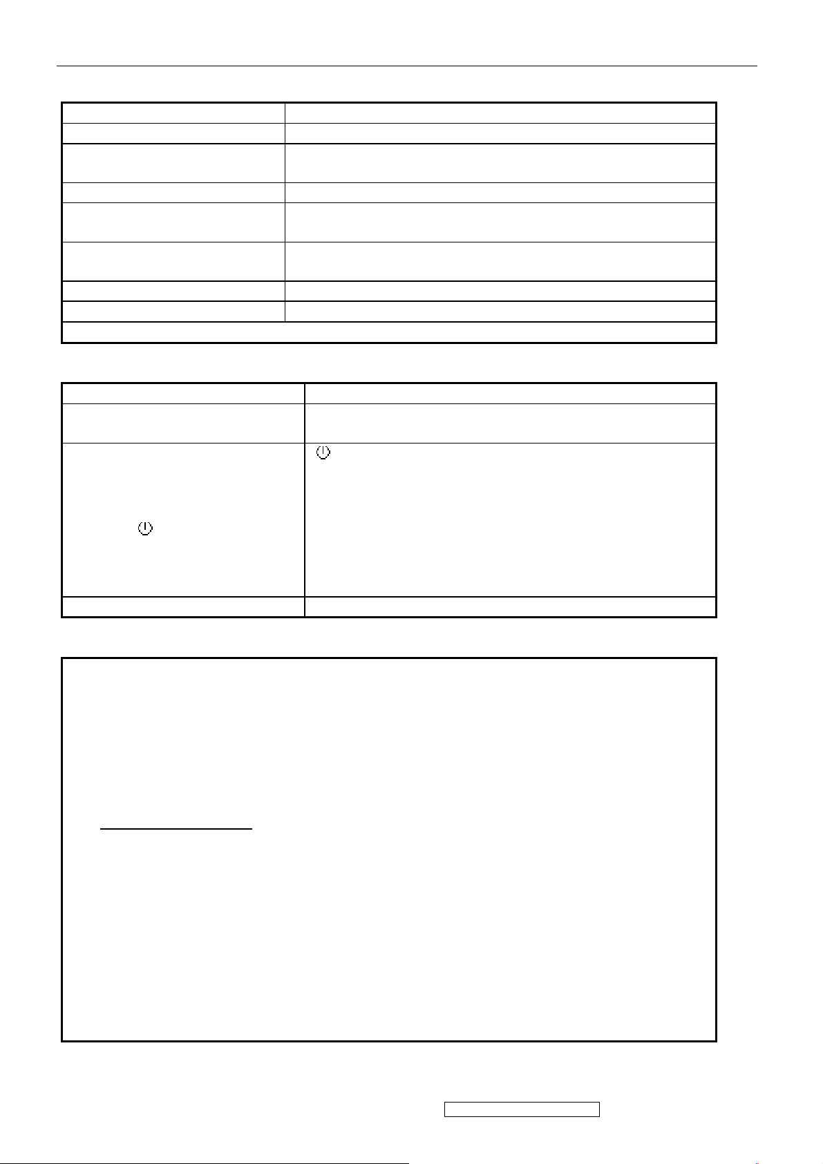
3. FRONT PANEL CONTROLS AND INDICATORS
Short Cuts Function from the button(s)
[1] Main Menu
[2] Auto Image Adjust
[▼] or [▲]
[▼]+ [▲] Recall both of Contrast and Brightness to default
[1] + [2]
[1] + [▼] + [▲]
(keep pushing 5 sec)
[1] + [▼] Power Lock
[1] + [▲] OSD Lock
Remark : All the short cuts function are only available while OSD off
Front Panel Hardware Controls
Power Switch (Front Head) Power Control, soft Power Switch.
Power LED (Front Head)
Front Panel Controls (Head)
[ 1 ] [ 2 ] [ ][▲] [▼]
Reaction Time OSD must fully appear within 0.5s after pushing [ 1 ]
Main Menu Controls
Auto Image Adjust
Contrast/Brightness*
1
Audio Adjust (For VA903m-3 only)
Volume*3, Mute*3
Color Adjust
sRGB, 9300K, 6500K(default), 5400, User Color [R, G, B]
Information
H Frequency, V Frequency, Pixel Clock, Resolution, Serial Number, Model Number,
“www.ViewSonic.com”
Manual Image Adjust
H. Size, H/V Position
,
Setup Menu
Language [English, French, German, Italian, Spanish, Finnish, Simplified Chinese
Traditional Chinese, Japanese], Resolution Notice, OSD Position*1, OSD Timeout, OSD
Background
Memory Recall
*1 These functions can be recalled to default by [▼]+ [▲]
2
These functions are not available under Native Resolution Mode
*
3
*
These functions setting can be recalled to default by [▼]+[▲] under audio mode
[Remark] Please refer to the detail in the Appendix C
To immediately activate Contrast menu. It should be
change to Brightness OSD by push button [2]
Toggle 720x400 and 640x400 mode when input 720x400
or 640x400 mode
White Balance (Not shown on user’s guide)
Green – On / Orange – Active Off
Dark = Soft Power Switch OFF
[ ] Power
[ 1 ] BUTTON 1
[ 2 ] Button 2
[▲] UP ARROW BUTTON
[▼] DOWN ARROW BUTTON
Note: Power Button, Button 1 and Button 2 must be
one-shot logic operation. (i.e. there should be no
cycling)
Fine Tune, Sharpness*2
ViewSonic Corporation Confidential - Do Not Copy VA903b-1_ VA903m-1
13
Page 17
Function descriptions
OSD Lock short cuts function for the buttons
The OSD lock will be activated by pressing the front panel control buttons "(1), & (▲)"
for 10 seconds. If the user then tries to access the OSD by pressing any of the buttons
"1", "▼", "▲", "2" a message will appear on the screen for 3 seconds showing "OSD
Locked". The OSD lock will be deactivated by pressing the front panel control buttons
"(1), & (▲)" again for 10 seconds.
Note1: When the OSD is locked will lock all functions, including “Volume” and “Mute”
Note 2: Status bar indicating OSD Lock or Unlock is in progress and when complete it
will indicate “OSD Locked”
Note 3: OSD Lock should not lock Power Button and Power Lock function
Power Lock short cuts function for the buttons
The power button lock will be activated by pressing the front panel control buttons "(1),
& (▼)" for 10 seconds. Locking the power button means that the user won't be able to
turn off the LCD while the power button is locked. If the user presses the power button
while it is locked, a message will appear on the screen for 3 seconds showing "Power
Button Locked". It also means that with the power button locked, the LCD would
automatically turn back "On" when power is restored after a power failure. If the power
button is not in the locked mode, then power should return to it's previous state when
power is restored after a power failure. The power button lock will be deactivated by
pressing the front panel control buttons "(1), & (▼)" again for 10 seconds
Note 1: Status bar indicating Power Button lock or unlock is in progress and when
complete it will indicate “Power Button Locked”
Note 2: Power should only be lockable in the “On State”
Memory Recall Actions
Memory Recall action on the analog and digital mode as below
1. Set the factory defaults as shown in Section 4-7
2. Clean all the mode setting buffer
3. Execute Auto Image Adjust
Note: Memory Recall should have no effect for Language, Power Lock, User Color Settings
Resolution Notice Actions
1. Resolution Notice OSD should show on screen after changing to non-native mode
for 30 sec
2. The OSD should disappear after 10 sec or by pushing button [1] or [2]
Resolution Notice function should be disabled when push button [2] under Resolution
Notice OSD
0-Touch™ Function Actions
1. Execute Auto Image Adjust when new mode detected, and save the settings to buffer
for further use
2. It should be reset by Memory Recall function
(Should not reset by power off, power unplug and others)
OSD Auto Save
The OSD shall save new settings when it is turned off by the user or when it times out.
There shall not be a separate save
ViewSonic Corporation Confidential - Do Not Copy VA903b-1_ VA903m-1
14
Page 18
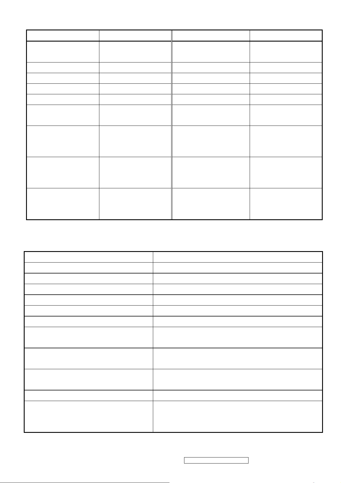
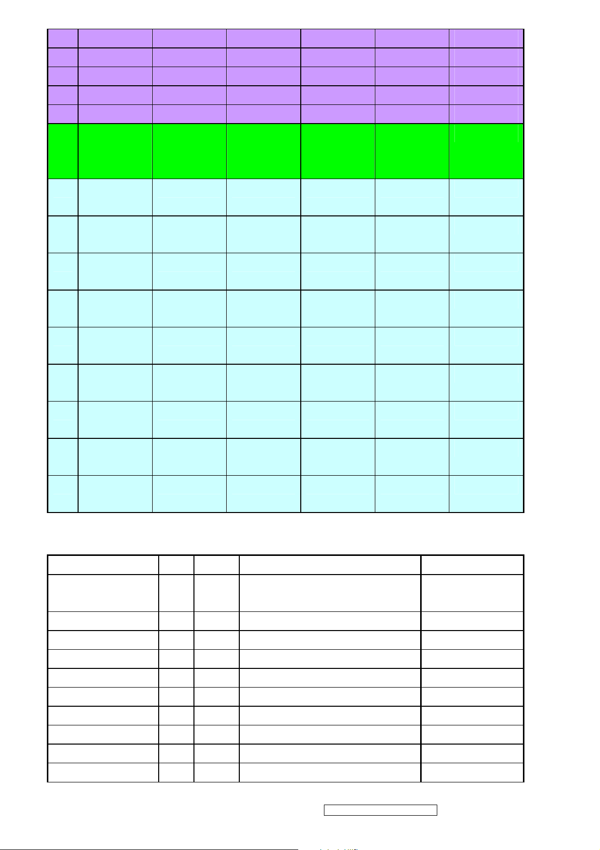
Factory Defaults
Item Defaults Item Defaults
Contrast 70% Volume
Brightness 100% Balance N/A
Color Temperature 6500K Treble N/A
Sharpness 0% Bass N/A
OSD H. Position 50% 720x400/640x400 720x400
OSD V. Position 50%
OSD Time Out 15 Sec
OSD Background Enabled
Resolution Notice Enabled
640x480@60Hz
720x480@60Hz
In SOG and Composite,
720x480@60Hz
640x480@60Hz
In SOG and Composite,
1152x864@75Hz
1152x870@75Hz
In SOG and Composite,
1280x768@60/75/85Hz
50%
(For VA903m-3 only)
640x480@60Hz
N/A
N/A
N/A
1024x768@60/75/85Hz
AUDIO INTERFACE (SPEAKER SPECIFICATION) (For VA903m-3 only)
Line input connection 3.5 mm stereo jack
Line input signal 1.0Vrms
Line input impedance >10 kOhm
Maximum power output (Electric) 1 W @ <15% distortion
Signal to Noise Ratio 50 dB
Frequency response 200 Hz – 20 Khz
Distortion <15% THD (@1kHz)
Vibration
Screen image
Connector PC99 requirement Audio
There should be no audible vibration with volume
at 100%. (Input signal within 1.0 Vrms)
There should be no affect on the screen image
stability under any conditions
Lime Green pantone # 577C
in
Cable type / length 3.5mm stereo cable / 1.8m length
Note: There is no guarantee <1 W power
Audio DPMS
ViewSonic Corporation Confidential - Do Not Copy VA903b-1_ VA903m-1
15
consumption in Active Off mode, when the Audio
Cable is connected
Page 19
4. Circuit Description
A. AC-DC CONVERTER
The power supply with a high-integrated green-mode PWM controller provides several features to
enhance the performance of power flyback converters.
U801 is a PWM controller and provides many protection functions.
U802 is a photo couple to transfer the feedback signal from the second side which U803 detected both of
the output DC voltage on 5V and 24V.
Z802 detected the working voltage on U801 and Q802 would pull down the voltage on U801 pin5 to
shut down U801 if feedback loop was failed.
R828 would be a dynamic load which was active while backlight was turned off and system still
working on, this kept 24V output voltage under 32V to protect the panel. After system went to
power saving mode, the R828 would no loaded. This was detected by Z803 active the R828 to load or
not.
B,Scaling Controller
Overview
Realtek RTD2523B series products are all-in-one LCD monitor controllers support up to
SXGA/XGA(optional), and integrate Realtek high performance ADC, TMDS Rx(optional), scaling engine,
OSD engine, LVDS TX, RSDS TX and so on. Moreover, all products are pin compatible in low pin count
package to save cost and make the design easier
General
z Embedded dual DDC support DDC1, DDC2B, DDC/CI
z Zoom scaling up and down
z Embedded Pattern Generator
z No external memory required.
z Require only one crystal to generate all timing
z Embedded reset control output
z Embedded crystal output to MICROP
z 3 channels 8 bits PWM output, and selectable PWM clock frequency.
Pin Description
(I/O Legend: A = Analog, I = Input, O = Output, P = Power, G = Ground)
ADC: 15 pins
Name
ADC_GND AG 27 ADC ground
ADC_REFIO AP 28 ADC band-gap voltage de-coupling 1.20V
ADC_VDD AP 29 Analog power (3.3V)
BLUE+ AI 30 Analog input from BLUE channel
BLUE- AI 31
ADC_GND AG 32 ADC ground
SOG/ADC_TEST AIO 33 SOG in/ADC test pin
GREEN+ AI 34 Analog input from GREEN channel
GREEN- AI 35 Analog input ground from GREEN
ADCB_VDD AP 36 Analog power (3.3V)
RED+ AI 37 Analog input from RED channel
I/O
Pin No Description Note
Analog input ground from BLUE channel
channel
ViewSonic Corporation Confidential - Do Not Copy VA903b-1_ VA903m-1
16
Page 20
RED- AI 38 Analog input ground from RED channel
ADC_GND AG 39 Analog ground
ADC_GND AG 40 Analog ground
ADC_VDD AP 41 Analog power (3.3V)
AHS AI 42 Analog HS input (10), (4), (5)
AVS AI 43 Analog VS input (2), (4), (5)
PLL: 8 pins
Name
XO AI 1 Reference clock output
XI AO 2 Reference clock input
DPLL_GND AG 3 Ground for digital PLL
DPLL_VDD AP 4 Power for digital PLL (3.3V)
APLL_VDD AP 5 Power for multi-phase PLL (3.3V)
PLL_TEST1 AIO 6 Test Pin 1 / IRQ#
PLL_TEST2 AIO 7 Test Pin 2/Power-on-latch for crystal out
APLL_GND AG 8 Ground for multi-phase PLL
I/O
Pin No Description Note
Frequency
Control Interface: 7 pins
Name I/O Pin No Description Note
SDIO [0] IO 54 Serial control I/F data in / Parallel port
data [0]
SDIO [1] / TCON [4] /
BBLU [0]
SDIO [2] / TCON [3] /
BBLU [1]
SDIO [3] / PWM2 /
TCON [2]
SCLK I 50 Serial control I/F clock (2), (3), (5)
SCSB I 111 Serial control I/F chip select (2), (3), (5)
RESET O 56 RESET output for Micron (2), (5), (6) / 2mA
Display & TCON/VIDEO-8 Port: 54 pins
IO 53 Parallel port data [1] / TCON [4] / TTL
BBLU [0]
IO 52 Parallel port data [2] / TCON [3] / TTL
BBLU [1]
IO 51 Parallel port data [1] / TCON [4] / PWM2 (1), (2), (3), / 2mA
(2), (3), / 2mA
(1), (2), (3), / 2mA
(1), (2), (3), / 2mA
■:LVDS+RSDS+TTLO ■:RSDS+TTLO ■:RSDS+TTLIO■:TTLO ■:TTLIO
Pin
NO.
6-bits
Dual RSDS
6 bits
Single RSDS
8/6 bits
Dual/Single
8 bits
Dual/Single
6 bits
Dual/Single
Note
TTL
S[3] /
TCON[2] /
PWM2
S[2] /
TCON[3]
(1), (2), (3)/
2mA
(1), (2), (3)/
2mA
51 S[3] /
TCON[2] /
PWM2
52 S[2] /
TCON[3]
S[3] /
TCON[2] /
PWM2
S[2] /
TCON[3]
LV DS
S[3] /
TCON[2] /
PWM2
S[2] /
TCON[3]
TTL
S[3] /
TCON[2] /
PWM2
S[2]
/BBLU[1] /
TCON[3]
ViewSonic Corporation Confidential - Do Not Copy VA903b-1_ VA903m-1
17
Page 21
53 S[1] /
S[1] /
S[1] /
S[1]/ BBLU[0]
S[1] /
(1), (2), (3)/
TCON[4]
55 PWM2 /
COUT /
TCON[13]
59 BB3P BB3P NC BBLU [7] BBLU [7]
60 BB3N BB3N NC BBLU [6] BBLU [6]
61 BB2P BB2P NC BBLU [5] BBLU [5]
62 BB2N BB2N NC BBLU [4] BBLU [4]
63 BB1P BB1P NC BBLU [3]/T0 BBLU [3]
64 BB1N BB1N NC BBLU [2]/T1 BBLU [2]
65 BCLKP BCLKP NC BGRN [1]/T2 TCON [6]
66 BCLKN BCLKN NC BGRN [0]/T3 TCON [5]
67 BG3P BG3P NC BGRN [7] BGRN [7]
68 BG3N BG3N NC BGRN [6] BGRN [6]
73 BG2P BG2P TODP BGRN [5]/T4 BGRN [5]
74 BG2N BG2N TODN BGRN [4]/T5 BGRN [4]
TCON[4]
PWM2 /
COUT /
TCON[13]
TCON[4]
PWM2 /
COUT /
TCON[13]
/ TCON[4]
PWM2 /
COUT /
TCON[13]
TCON[4]
PWM2 /
COUT /
TCON[13]
2mA
(1), (2), (3)/
2mA
75 BG1P BG1P TOCLKP BGRN [3]/T6 BGRN [3]
76 BG1N BG1N TOCLKN BGRN [2]/T7 BGRN [2]
77 BR3P BR3P TOCP BRED [7]/T8 BRED [7]
78 BR3N BR3N TOCN BRED [6]/T9 BRED [6]
79 BR2P BR2P TOBP BRED [5]/T10 BRED [5]
80 BR2N BR2N TOBP BRED [4]/T11 BRED [4]
81 BR1P BR1P TOAP BRED [3]/T12 BRED [3]
82 BR1N BR1N TOAP BRED [2]/T13 BRED [2]
85 AB3P NC TEDP ABLU [7]/T14 ABLU [7]
86 AB3N NC TEDN ABLU [6]/T15 ABLU [6]
87 AB2P NC TECLKP ABLU [5]/T16 ABLU [5]
88 AB2N NC TECLKN ABLU [4]/T17 ABLU [4]
89 AB1P NC TECP ABLU [3]/T18 ABLU [3]
90 AB1N NC TECN ABLU [2]/T19 ABLU [2]
91 ACLKP NC TEBP ABLU [1]/T20 TCON [1]
92 ACLKN NC TEBN ABLU [0]/T21 TCON [0]
93 AG3P NC TEAP AGRN [7]/T22 AGRN [7]
94 AG3N NC TEAN AGRN [6]/T23 AGRN [6]
99 AG2P TCON [11] NC AGRN [5]/T24 AGRN [5]
100 AG2N TCON [10] NC AGRN [4]/T25 AGRN [4]
101 AG1P TCON [9] NC AGRN [3]/T26 AGRN [3]
102 AG1N TCON [8] NC AGRN [2]/T27 AGRN [2]
103 AR3P TCON [7] NC ARED [7]/T28 ARED [7]
ViewSonic Corporation Confidential - Do Not Copy VA903b-1_ VA903m-1
18
Page 22
104 AR3N TCON [6] NC ARED [6]/T29 ARED [6]
105 AR2P TCON [5] NC ARED [5]/TH ARED [5]
106 AR2N TCON [1] NC ARED [4]/TV ARED [4]
107 AR1P TCON [0] NC ARED [3]/TE ARED [3]
108 AR1N NC NC ARED [2]/TK ARED [2]
113 PWM2 /
COUT /
TCON[12]
114 TCON [11]
/V[0]
115 TCON [10]
/V[1]
116 TCON [9] /
V[2]
117 TCON [8] /
V[3]
118 TCON [7] /
V[4]
119 TCON [6] /
V[5]
122 TCON [5] /
PWM2 /
COUT /
TCON[12]
V [0] V [0] ARED [0] TCON [11] (1), (7), (8)
V [1] V [1] BRED [1] TCON [10] (1), (7), (8)
V [2] V [2] BRED [0] TCON [9] (1), (7), (8)
V [3] V [3] AGRN [1] TCON [8] (1), (7), (8)
V [4] V [4] AGRN [0] TCON [7] (1), (7), (8)
V [5] V [5] DHS DHS (1), (7), (8)
V [6] V [6] DVS DVS (1), (7), (8)
PWM2 /
COUT /
TCON[12]
ARED [1] PWM2 /
COUT /
TCON[12]
(9)
V[6]
123 TCON [1] /
V[7]
124 TCON [0] /
VCLK
V [7] V [7] DENA DENA (1), (7), (8)
VCLK VCLK DCLK / TCLK DCLK / TCLK (1), (7), (8)
TMDS: 18 pins
Name I/O Pin No
TMDS_TST/ PWM1 AIO 9 TMDS_TEST Pin / PWM1 /
TMDS_GND G 10
TMDS_VDD P 11 (3.3V)
EXT_RES A 12 Impedance Match Reference.
TMDS_VDD P 13 (3.3V)
RX2P I 14 Differential Data Input
RX2N I 15 Differential Data Input
Description
Power-on-latch for serial / parallel port
Note
TMDS_GND G 16
RX1P I 17 Differential Data Input
RX1N I 18 Differential Data Input
ViewSonic Corporation Confidential - Do Not Copy VA903b-1_ VA903m-1
19
Page 23
TMDS_VDD P 19 (3.3V)
RX0P I 20 Differential Data Input
RX0N I 21 Differential Data Input
TMDS_GND G 22
RXCP I 23 Differential Data Input
RXCN I 24 Differential Data Input
TMDS_GND G 25
TMDS_VDD P 26 (3.3V)
PWM Interface: 3-2=1 pin (PWM1, PWM2 can be selected from 1 of 3 possible pins.)
Name
I/O
Pin No Description Note
PWM2 / TCON [2] / S
[3]
PWM2 / TCON [13] /
COUT
PWM2 / TCON [12] /
COUT
PWM1 / TMDS_TST AIO 9 PWM1/ TMDS_TEST Pin /
PWM1 / DDCSDA /
TCON [1] / BBLU [0]
PWM1 / DDCSDA2
(HDCP) / TCON [7]
PWM0 / REFCLK IO 112 PWM0 / (In / out) test pin for DCLK /
O 51 PWM2 / TCON [2] / SDIO [3] (1), (2), (3), (5), (8),
O 55 PWM2 / TCON [13] / Crystal out (2), (8), (9)
O 113 PWM2 / TCON [12] / Crystal out (2), (8), (9)
Power-on-latch for serial / parallel port
IO 47 PWM1 / DDC serial control I/F data input
/ output / TCON [4]
IO 125 PWM1 / DDC serial control I/F data input
/ output / TCON [7]
Video8 even-odd signal
DDC Channel: 4 pins
Name I/O Pin No Description Note
(2), (7), (8)
(1), (2), (3), (5), (8),
(1), (2), (3), (5), (8),
(2), (9)
DDCSCL / TCON [0] /
BBLU [1]
DDCSDA / TCON [1] /
PWM1 / BBLU [0]
DDCSCL2 (HDCP) /
TCON [5]
DDCSDA2 (HDCP) /
TCON [7] /PWM1
I 46 DDC serial control I/F clock / TCON [0] /
TTL BBLU [1]
IO 47 DDC serial control I/F data input / output
/ TCON [1] / PWM1 / TTL BBLU [0]
I 126 DDC serial control I/F clock / TCON [5] (2), (3), (5)
IO 125 DDC serial control I/F data input / output
/ TCON [7] / PWM1
(2), (3), (5)
(1), (2), (3), (5), (6),
(8)/ 8mA /no slew
(1), (2), (3), (5), (6),
(8)/ 8mA /no slew
Power & Ground: 22 pins
Name
3.3V Power P 49,121 VCCIO: 2
I/O
Pin No Description
ViewSonic Corporation Confidential - Do Not Copy VA903b-1_ VA903m-1
20
Page 24

3.3V Ground G 48,120 GNDIO: 2
3.3V Power P 58,71,83,95,110 PVCC: 5
3.3V Ground G 57,72,84,96,109 PGND: 5
2.5V Power P 45,69,98,127 VCCK: 4
2.5V Ground G 44,70,97,128 GNDIK: 4
Note: (1) TTL compatible CMOS Input (Vt=1.7V); VCC=3.3V;
(2) 5V tolerance pad;
(3) Internal 75K Ohms pull high resistor.
(4) Internal 75K Ohms pull low resistor.
(5) Schmitt trigger CMOS Input (Vt=1.4-~2.2V);
(6) Open-Drain, Output Drive low & Pull-high.
(7) Bi-directional input/output
(8) Programmable driving current (2~10mA)
(9) TTL output 5V & 3.3V
(10) 4V tolerance pad
C, MTV512M
The MTV512M micro-controller is an 8051 CPU core
embedded device especially tailored for flat panel
display applications. It includes an 8051 CPU core,
768-byte SRAM, 4 channels of 6-bit ADC, 3 external
counters/timers, 6 channels of PWM DAC, VESA
DDC interface, and a 64K-byte internal program
Flash-ROM memory in 44-pin PLCC package
FEATURES
• 8051 core, 12MHz operating frequency with
single/double CPU clock option
• 0.35um process; 3.3V power supply
• 768-byte RAM; 64K-byte program Flash memory
• Maximum 6 channels of PWM DAC
• Compliant with VESA DDC1/2B/2Bi/2B+ standard
• Dual slave IIC addresses; two H/W auto transfer
DDC1/DDC2x data for both D-sub and DVI
interfaces
• Watchdog timer with programmable interval
• Support external counters/timers, 1 & 2
• Single/double frequency clock output
• Two external interrupts, INT1 is shared with Slave
IIC interrupt source.
• Maximum 4 channels of 6-bit ADC
• Flash-ROM code protection selection
• 44-pin PLCC package
D. INVERTER
In order to drive the CCFLs embedded in the panel module, there is a push-pull inverter to convert by the controller.
from input 24V up to hundreds of AC voltage output peak to peak.
The inverter is formed by symmetric in order to drive the separate lamp modules.
The input stage consists of a PWM controller, push-pull inverter, and switching MOSFET to convert DC input into
ViewSonic Corporation Confidential - Do Not Copy VA903b-1_ VA903m-1
21
Page 25

AC output.
The output stage consists of a tuning capacitor, transformer, and push-pull MOSFET pair to boost AC output up to
hundreds of voltage peak to peak.
And one resister is serial to lamp for output voltage feedback.
There are two signals which control the inverter come from system to turn on the inverter and control brightness.
Logic “low” level which send to U901 is turn on the inverter.
BL-ADJ signal control brightness by DC level which was integral from PWM signal.
ViewSonic Corporation Confidential - Do Not Copy VA903b-1_ VA903m-1
22
Page 26
5. Adjusting Procedure
1. Function test
1.1 products
19” LCD Monitor
1.2 test equipment
Color video Signal& pattern (Or PC with SXGA resolution and a sound card)
1.3 Test Condition
Before function test and alignment ,each LCD Monitor should be warmed up at least
30 minutes with the following conditions:
A: in roon temperature
B with full white screen ,RGB ,and black
C. with cycled display model:
1280 x 1024 @ 60Hz
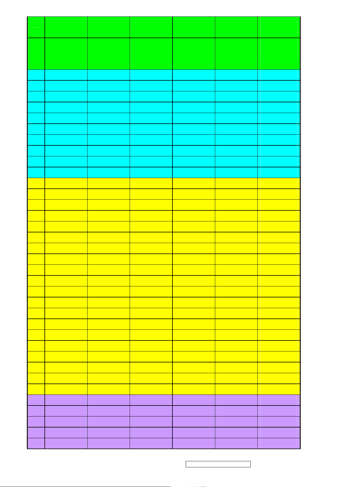
1.4 Test display& Pattern
1.4.1 Compatible model
Item Timing Analog
1 640 x 350 @ 70Hz, 31.5kHz
2 640 x 480 @ 50Hz, 24.68KHZ
3 640 x 480 @ 60Hz, 31.5kHz
4 MAC 640 x 480 @ 67Hz, 35.0kHz
5 640 x 480 @ 72Hz, 37.9kHz
6 640 x 480 @ 75Hz, 37.5kHz
7 640 x 480 @ 85Hz, 43.27kHz
8 720 x 400 @ 70Hz, 31.5kHz
9 800 x 600 @ 56Hz, 35.1kHz
10 800 x 600 @ 60Hz, 37.9kHz
11 800 x 600 @ 72Hz, 48.1kHz
12 800 x 600 @ 75Hz, 46.9kHz
13 800 x 600 @ 85Hz, 53.7kHz
14 MAC 832 x 624 @ 75Hz, 49.7kHz
15 1024 x 768 @ 60Hz, 48.4kHz
16 1024 x 768 @ 70Hz, 56.5kHz
17 1024 x 768 @ 72Hz, 58.1kHz
18 1024 x 768 @ 75Hz, 60.0kHz
19 1024 x 768 @ 85Hz, 68.67KHZ
20 1152 x 864 @ 75Hz, 67.5KHZ
21 MAC 1152x870@75HZ, 68.68KHZ
22 1280 x 960 @ 60Hz, 44.93KHZ
23 1280 x 960 @75Hz, 56.25KHZ
24 1280 x 1024 @ 60Hz, 63.98KHZ
25 1280 x 1024 @ 75Hz, 79.97KHZ
*1. Tolerance ≧ ± 2kHz.
Yes
Yes
Yes
Yes
Yes
Yes
Yes
Yes
Yes
Yes
Yes
Yes
Yes
Yes
Yes
Yes
Yes
Yes
Yes
Yes
Yes
Yes
Yes
Yes
Yes
*2. Any timing not in the list, it should display as normal or show o n “OUT OF RANGE” OSD message without
blanking.
*3. The image quality of 85Hz mode might be worse than 75Hz.
ViewSonic Corporation Confidential - Do Not Copy VA903b-1_ VA903m-1
23
Page 27

ViewSonic Corporation Confidential - Do Not Copy VA903b-1_ VA903m-1
24
Page 28

ViewSonic Corporation Confidential - Do Not Copy VA903b-1_ VA903m-1
25
Page 29

Firmware Update Procedure
1. The monitor’s firmware update for VA903m/b have two method.
Download the MCU IC by the fire machine. This proc edure is finished in SMT.
ISP Method. When the monitor ’s BIOS isn’t exist or firmware isn’t final program, this method Is worked by ISP
Cord with monitor.
2. VA903m/b monitor upgrade firmware by ISP Cord.
Equipment Needed
- USB cable for print port *1
- VGA cable*1
- LPT cable (25pin)*1
- AC power cable*1
- ISP fire cord (the fixture is made in TE ) for firmware upgrade*1
- Power adapter for firmware upgrade (this adapter is made in TE)*1
- A computer with Windows XP
- VA903m/b monitor ( no firmware)
- a additional monitor for system display
- ISP & ISP3.0program
NOTE:
The fixtures for firmware upgrade provide two differe nt methods to fire. Please check you monit or’s Main board,
refer to MCU-RSIC type and choose the method.
Below form appear the relation between the method and the MCU-RSIC type
METHOD
A
B
MCU
MYSON
OTHER
ASIC
M-STAR & NOVATEK
REALTEK
LPT PORT
JUMPER
PIN2-3 CLOSED
PIN1-2 CLOSED
TEST PC Fixture ISP_CORD Fixture POWER_ADAPTER
ViewSonic Corporation Confidential - Do Not Copy VA903b-1_ VA903m-1
26
Page 30

LPT Cable AC power Cable VGA Cable
ISP3.0
SOFT
USB FOR PRINT
2.2. Setup Procedure
2.2.1 Connect PO1 of ISP fixture with print port of computer by LPT cable
2.2.2 Connect PO2 of ISP fixture with USB port of computer by USB cable
2.2.3 Connect PO3 of ISP fixture with monitor VGA port by VGA cable
2.2.4 Connect mouse, keyboard, AC power, monitor with computer
2.2.5 Plug AC cable in power adapter AC jack
2.2.6 Connect power adapter DC_OUTPUT port to main board DC_IN port
2.2.7 Connect PO3 of ISP fixture with VGA port of monitor’s main board by VGA cable
ViewSonic Corporation Confidential - Do Not Copy VA903b-1_ VA903m-1
27
Page 31

PO2 to USB cable PO1 to LPT cable
AC JACK
DC_IN port
VGA port
jumper
PO3 to VGA cable
NOTE:
Do STEP2.2.6 and STEP2.2.7 for monitor’s main board only. Monitor firmware upgrade will jump this step.
ViewSonic Corporation Confidential - Do Not Copy VA903b-1_ VA903m-1
28
Page 32

2.3. Soft install
Install ISP3.0 program by selecting and clicking “…\isp3.0\setup.exe”, press “YES” or “NEXT” buttons
until setup is complete.
ViewSonic Corporation Confidential - Do Not Copy VA903b-1_ VA903m-1
29
Page 33

ViewSonic Corporation Confidential - Do Not Copy VA903b-1_ VA903m-1
30
Page 34

ViewSonic Corporation Confidential - Do Not Copy VA903b-1_ VA903m-1
31
Page 35

Installation will create a icon for ISP application in “START MENU”\PROGRAM
Press “finish” button exit setup
ViewSonic Corporation Confidential - Do Not Copy VA903b-1_ VA903m-1
32
Page 36

STEP1: Choose the DCC written Program
set up the DCC written fixture ,check whether the connection between main board is in well
condition ,see attached file 1.1&1.2 per the product model ,choose the corresponding Model, DCC
written process, the model mr171-AAA should apply the SIP Program
ViewSonic Corporation Confidential - Do Not Copy VA903b-1_ VA903m-1
33
Page 37

STEP2: Creat security file
Choose the Tab "create Security File " to enter next Dialogue Item
ViewSonic Corporation Confidential - Do Not Copy VA903b-1_ VA903m-1
34
Page 38

STEP3: Input the related parameter, save them and take up the next step
STEP4: Choose the Tab MTV TYPE
Choose the MTV512M64 from the TAB ISP ITEMS
DCC Written model Diagram Table as below
ViewSonic Corporation Confidential - Do Not Copy VA903b-1_ VA903m-1
35
Page 39

STEP5: DCC WRITTEN methods
ViewSonic Corporation Confidential - Do Not Copy VA903b-1_ VA903m-1
36
Page 40

SETP6: Choose the DDC Written BIOS document
Choose the Tab LOAD MCU FILE,Looking up the related BIOS document in my Computer ,and Point
the confirm Tab
when the BIOS Documents' loading is successful ,you can find the picture as above
ViewSonic Corporation Confidential - Do Not Copy VA903b-1_ VA903m-1
37
Page 41

Step 7.Confirm the BIOS'S check sum
In the above attached Display picture ,you should check whether the check sum's Data comply
to the bios' DCC written, if there is no problem ,pls press the run menu to write
If showed the picture as above pls check whether the DDC write fixture is well Connected with PC
the power board is power on and the program's setup is all right
ViewSonic Corporation
38
Confidential - Do Not Copy VA903b-1_ VA903m-1
Page 42

The normal program is writing
The program has finished writing
ViewSonic Corporation Confidential - Do Not Copy VA903b-1_ VA903m-1
39
Page 43

Disassembly Procedure
1. Remove the hinge cover
2. Unscrew the back cover’s screw
3. open the back cover ,pull out the speaker wire
ViewSonic Corporation Confidential - Do Not Copy VA903b-1_ VA903m-1
40
Page 44

4. Tear off the aluminum foil where fix up the light
Tear off the aluminum foil where cover the FFC cable,take out the key board from bezel ,pull out
5.
FFC cable from the main board;
6. pull out the two pcs screw form the main board
ViewSonic Corporation Confidential - Do Not Copy VA903b-1_ VA903m-1
41
Page 45

7. pull out the two screws where lie in the two sides of the frame
8. pull out the screws which fix up the bezel and then take out the bezel
9. Take out the screw which covers the shield
ViewSonic Corporation Confidential - Do Not Copy VA903b-1_ VA903m-1
42
Page 46

10. pull out the lamp wire material
11. take out the screw form the power board ,pull out the power boards’ connecter wire
12. take out the FCC Cable AL where lies in the panel ,pull out the FCC cable
ViewSonic Corporation Confidential - Do Not Copy VA903b-1_ VA903m-1
43
Page 47

13. take out the main board’s screw
14. Remove the fame down towards
ViewSonic Corporation Confidential - Do Not Copy VA903b-1_ VA903m-1
44
Page 48

Packing Procedure
1.1 Paste production film to protect the monitor screen.(Figure 1)
tape
Production film
1.2 Put the monitor in the PE bag and seal bag with type (Figure 2)
tape
1.3 Put the cushions on the monitor.(Figure 4)
ViewSonic Corporation Confidential - Do Not Copy VA903b-1_ VA903m-1
45
Page 49

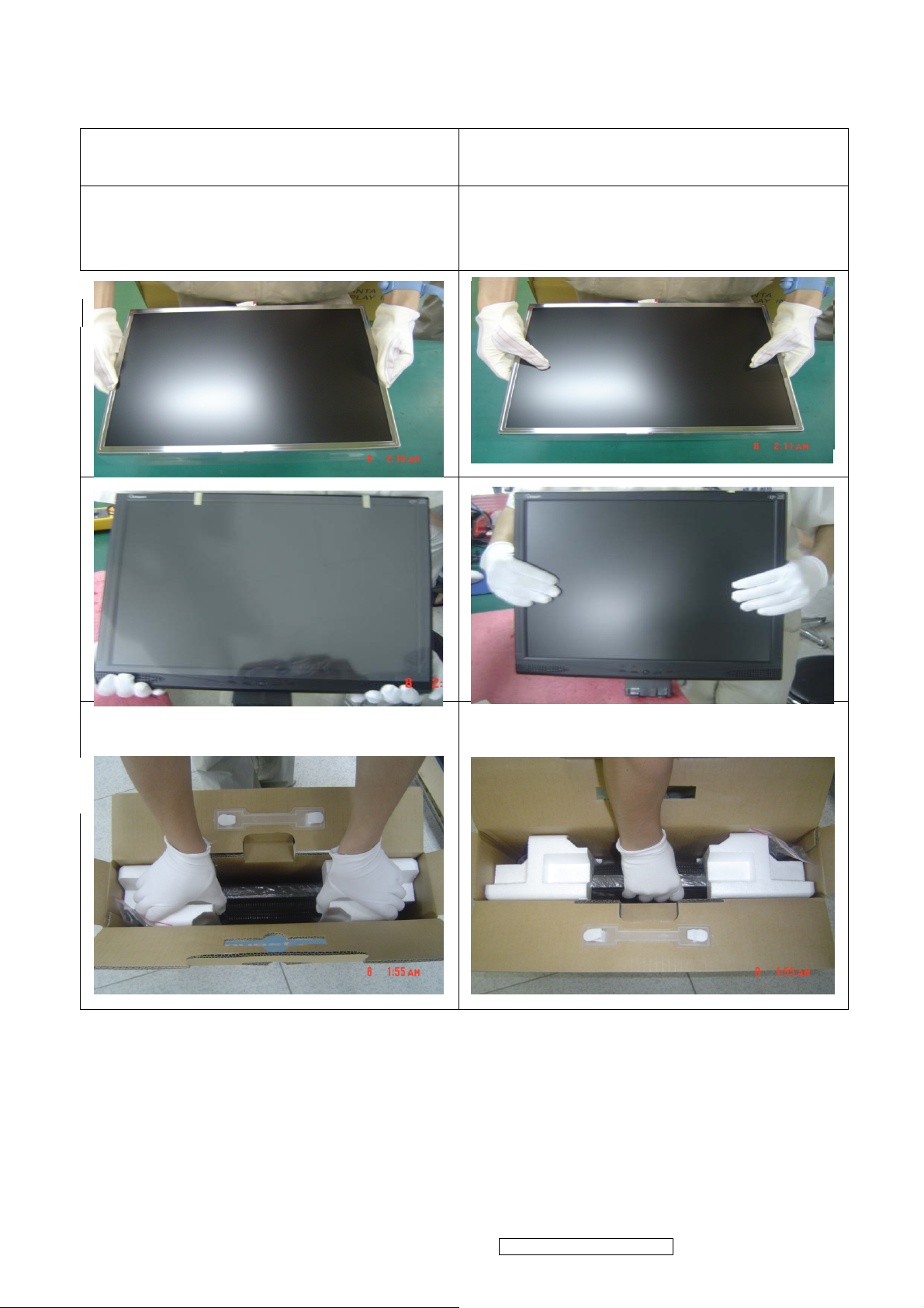
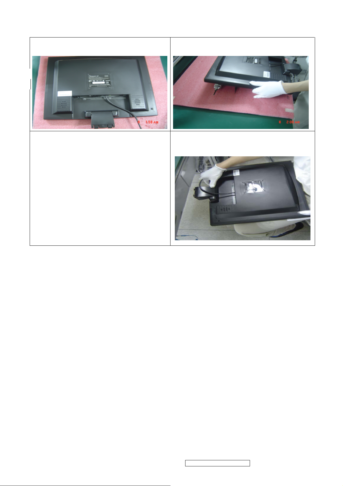
1.4 Put the base in the EPE bag. and then,place the base on the cushions ,as figure;
1.4.Place the monitor into the carton and then put all accessories into carton .At last,close the
carton.
Power cord
Use ‘s Guide
Base signal cord
ViewSonic Corporation Confidential - Do Not Copy VA903b-1_ VA903m-1
46
Page 50

6. Troubleshooting Flow Chart
Main Procedure
Start
Connect all of devices to
the LCD monitor
Power On
Is indicator LED
light?
Yes
No
A. Power Circuit
Troubleshooting
1
ViewSonic Corporation Confidential - Do Not Copy VA903b-1_ VA903m-1
47
Page 51

1
Is backlight on?
Yes
Display Performance
O.K.?
Yes
Function Adjustment
O.K.?
Yes
Audio Function O.K.?
No
No
No
No
B. Backlight
Troubleshooting
C. Performance
Troubleshooting
D. Function
Troubleshooting
E. Audio
Troubleshooting
No Trouble Found
End
ViewSonic Corporation Confidential - Do Not Copy VA903b-1_ VA903m-1
48
Page 52

A. Power Circuit Troubleshooting
Start
Change AC/
DC Adapter
Retry Power
On
End
Change Main
Board & Retry
No Trouble Found
End
End
ViewSonic Corporation Confidential - Do Not Copy VA903b-1_ VA903m-1
49
Page 53

B. Backlight Troubleshooting
Start
Change
Inverter and
Retry
Change
Main
Board&
Retry
End
End
Backlight
Change
Module
No Trouble Found
End
End
ViewSonic Corporation Confidential - Do Not Copy VA903b-1_ VA903m-1
50
Page 54

C. Performance Troubleshooting
Start
Screen is
scrolling?
NO
Screen is
flickering?
NO
LCD Line Defect?
NO
Yes
YES
YES
Change VGA
Cable
YES
Change
Inverter Board
YES
Change LCD
Module
YES
No
NO
Change Main
Board
YES
Change Main
Board
YES
NO
Change LCD
Module
YES
Bad Uniformity?
NO
Is screen white?
NO
2
YES
YES NO
Change LCD
Module
YES
Check
Connector
YES
Change Main
Board
YES
ViewSonic Corporation Confidential - Do Not Copy VA903b-1_ VA903m-1
51
Page 55

2
Screen with noise or line
bar?
No
Screen is smaller?
Yes
Prss Reset Button from
front panel control
No
Change Main
Board
Make sure relution is set
at default
No
YesYes
End
No
No Trouble Found
End
Yes
Yes
Reset O.K.?
No
Change Main
Board
ViewSonic Corporation Confidential - Do Not Copy VA903b-1_ VA903m-1
52
Page 56

D. Function Troubleshooting
Start
Control Menu not
Functioning?
Yes
No
Change
Control Board
and Retry?
No
Change Main
Board
No Trouble Found
End
Yes
ViewSonic Corporation Confidential - Do Not Copy VA903b-1_ VA903m-1
53
Page 57

E. Audio Troubleshooting
Start
Make sure sound output, Audio
cable is OK.
No Sound
No
Sound is broken?
No
Yes
Yes
Change
Speaker
Change
Speaker
Volume
Unadjustable?
No
No Trouble Found
End
Yes
Change Main
Board
ViewSonic Corporation Confidential - Do Not Copy VA903b-1_ VA903m-1
54
Page 58

7. Recommended Spare Parts List
ViewSonic Model Number: VS11372
Rev: 1b
Serial No. Prefix: QAV
Item ECR/ECN ViewSonic P/N Ref. P/N Location Universal number#
1
Accessories:
2 Main Board - LM/MR19I-AAA B-00006501 XLM191A040002
PC Board Assembly:
3 Key Board - SVA B-00006502 XLM191A050001
4 Inverter Board + Power Board Rev.1 B-00008053 XLM1700390015-SF
6 Front Panel (SILVER ) +Button Added on 10/16/06 C-00008154 XLM191A100002
Cabinets:
8 Back Cover - (Housing Assy(BLACK) RGB+Audio) Added on 10/16/06 C-00008155 XLM191A110002
9 Base Assembly (Black) C-00008090 XLM171A280002
10 AUDIO CABLE 26A WG UL2547 CB-00005758 W0026918A0142
Cables:
11 VGA Cable 30AWG UL20276 (Video Cable) CB-00006504 W0926418AQ951
12 LCD Module (HSD190ME13-A10) 19" LVDS Hannstar E-00008009 E34862190H304
Electronic
13 LCD Module 19" HSD190ME13-A16 Hannstar Added on 10/02/06 E-00005792 E34862190H303-A
Components:
14
Hardware:
15 Generic Foam (Set) P-00001347 30833
Packing Material:
16 Generic Box , Rsc 22 1/2"x 11 3/4"x 23 1/2" P-00002515 20653
17 Craft Foam (Left) P-00008071 F20133191A002
18 Craft Foam (Right) P-00008072 F20143191A002
19
Remark 1:
Remark 2: All revised RSPLs with newly added items or any change made should be highlighted and correlated with the ECN/ECR approved by ViewSonic Corporation. This is to
Description
Power Cord A-00008026 W402091809531
Bracket - LM/MR19I-AAA Black CMO HW-00008014 XLM191A200002
Craft Box Updated Vendor F400718191A02
Above listed items are examples, supplier can expand the rows to add more necessary items.
eliminate repeated cross checks of each item between this version and prior versions.
Part # on 10/12/06 F4007K4191A02
P-00008074
RECOMMENDED SPARE PARTS LIST (VA903b-3)
ViewSonic Model Number: VS11372
Rev: 1b
Serial No. Prefix: QAU
RECOMMENDED SPARE PARTS LIST (VA903m-3)
Item ECR/ECN ViewSonic P/N Ref. P/N Location Universal number#
1
Accessories:
2 Main Board - LM/MR19I-AAA B-00006501 XLM191A040002
PC Board Assembly:
3 Key Board - SVA B-00006502 XLM191A050001
4 Inverter Board + Power Board Rev.1 B-00008053 XLM1700390015-SF
5 Base Assembly (Midnight Gray) C-00006583 XLM171A280003
Cabinets:
6 Updated Vendor XLM191A100003
7 Part # on 10/12/06 XLM191A100002
8 Updated Vendor XLM191A110001
9 Part # on 10/12/06 XLM191A110002
10 Audio Cable - 1800mm 26A WG UL2547 CB-00005758 W0026918A0142
Cables:
11 VGA Cable 30AWG UL20276 (Video Cable) CB-00006504 W0926418AQ951
12 LCD Module (HSD190ME13-A10) 19" LVDS HANNSTAR E-00008009 E34862190H304
Electronic
13 LCD Module 19" HSD190ME13-A16 LVDS Hannstar VA/VG SERIES) Added on 10/02/06 E-00005792 E34862190H303-A
Components:
14
Hardware:
15 Generic Foam (Set) P-00001347 30833
Packing Material:
16 Generic Box , Rsc 22 1/2"x 11 3/4"x 23 1/2" P-00002515 20653
17 Craft Foam (Left) P-00008071 F20133191A002
18 Craft Foam (Right) P-00008072 F20143191A002
19
Power Cord - USA A-00008026 W402091809531
Front panel (Bezel Assembly)
Back Cover (Housing Assy RGB Only)
Bracket - SVA HW-00008013 XLM191A200001
Craft Box P-00008073
Remark 1: Above listed items are examples, supplier can expand the rows to add more necessary items.
All revised RSPLs with newly added items or any change made should be highlighted and correlated with the ECN/ECR approved by ViewSonic Corporation. This is to eliminate
Remark 2:
repeated cross checks of each item between this version and prior versions.
Description
C-00008088
C-00008089
Updated Vendor F400718191A01
Part # on 10/12/06 F4007K4191A01
ViewSonic Corporation Confidential - Do Not Copy VA903b-1_ VA903m-1
55
Page 59

BOM LIST (VA903m-3)
ViewSonic Model Number: VS11372
Rev: 1b
Serial No. Prefix: QAV
Item ViewSonic P/N Ref. P/N Description Location Universal number# Q'ty
1 N/A E015-006-W (10mm*14mm) Bird logo 1
2 N/A E015-016-1-W VIEWSONIC38MM 1
3 E-00008009 E34862190H304
4 N/A F0004191AK001
5 N/A F0010171A3001
6 N/A F001217043001 Explanation card LM/LM1704 ENGLISH L210*W148mm for Viewsonic REV:0
7 N/A F101415170401 MARK LM/LM1704 L11*W11mm energy star 1
8 N/A F102506191A04 Safety Label LM/MR19I-AAA L89.5*W49.5mm for viewsonic (VA903m) REV:1
9 N/A F103015170401 Blank Label LM/LM1704 L50*W25mm 1
10 DC-00008065 F103015171A01 Blank Label LM/MR17I-AAA L36*W9mm for viewsonic china 1
11 N/A F103915170401 CARTON LABEL(UPC) LM/LM1704 L76*W76mm FOR VIEWSONIC 1
12 N/A F103915171A01 CARTON LABEL LM/MR17I-AAA L89*W58mm for viewsonic 8ms 1
13 N/A F104515170401 RATING LABEL LM/LM1704 L7*W7mm for Viewsonic 1
14 P-00008071 F20133191A002 POLYETHYLENE-L EPS LM/MR19I-AAA L155*W155*H483mm 1
15 P-00008072 F20143191A002 POLYETHYLENE-R EPS LM/MR19I-AAA L155*W155*H483mm 1
16 N/A F300250000047 BAG /PE L550*W480*T0.03mm transparent 1
17 N/A F300272501501 PLASTIC BAG LDPE L250*W150*T0.08mm 1
18 N/A F4007K4191A02
19 N/A F401422LM0001 PARTITION SUPPORT BC LM/MONITOR series L800*W50*H50*T5mm 0.035
20 N/A F401422LM0003 PARTITION SUPPORT BC LM/MONITOR series L2000*W50*H50*T5mm 0.071
21 N/A F401918191A01
22 N/A F50301F199002 PALLET SMOKE WOOD LM/F199 L1140*W980*H120mm 0.017
23 N/A F801191000005 CD M/MR19I-AA For viewsonic HSD REV:1 1
24 N/A F900181000001 PE LIMPID W500*T0.03mm1500m/ROLL PACKTHREAD PP WHITE 0.0003
25 N/A F9008G2000002 PACKTHREAD PP WHITE W14.5mm*T0.8mm 1300m/roll 0.0003
26 N/A M101082807401 SCREW COPPER Φ2.8*L7mmWITH NICKEL 2
27 N/A M105223004401 SCREW MACHINE (Binding) Φ3.0mm L5mmNICKEL 15
28 N/A M105244006401 SCREW BINDING Φ4.0*L6mm WITH NICKEL AD WASHER 1
29 N/A M108224008401 MACHINE SCREW Φ4.0*L8mm NICKEL 4
30 N/A M115233008401 SCREW TA PW Φ3.0*L8.0mm NICKEL Washer(Φ10.0mm) 1
31 N/A M621700LM0390-G Main Bracket SECC LM/MR19I-AAA REV:0 1
32 N/A P36D1C2010001 MYLAR L410*W320*T0.12mm LIMPID 1
33 N/A P440703800002 RUBBER CUSHION(housing) Φ7.45*Φ3.2*H8mm BLACK 4
34 N/A P441508980001 RUBBER CUSHION /RUBBER L15*W8*T9.8mm BLACKL15*8*9.8 BLACK 2
35 N/A P532015A20001 CUSHION L20*W15*T12mmEVA 3
36 N/A P705A995LM020-A Back Cover ABS HB BLACK Shoot shaping LM/MR17I-AAA REV:0 1
37 N/A V5004AP150201 ADHESIVE TAPE L25000*W15*T0.25mm 25m/ROLL(YW0910300002) 0.01
38 N/A V900505020003 AL FOIL L50×W30×T0.10mm 1
39 N/A V900505030001 AL FOIL L100xW40xT0.07mm 1
40 N/A V900505030007 AL FOILL100xW30*T0.35mm(Y78400004G*1) 4
41 CB-00006504 W0926418AQ951 VGA CABLE 30AWG UL20276 L1800mm 15PIN black 1
42 A-00008026 W402091809531
43 CB-00008033 W47A103015003 AC POWER CORD UL 22AWG L150cm BLACK YISHENG 1
Substitute N/A W47A103015004 FFC WIRE CY050408001 P=1.0mm 30PIN L150mm HUNG FU 1
44 CB-00008043 W47B101030001 FFC WIRE CY050408001 P=1.0mm 30PIN L150mm HANQUAN 1
45 B-00008053 XLM1700390015-SF
Substitute N/A XLM1700390015-SH
46 C-00008090 XLM171A280002 BASE ASSY LM/MR17I-AAA BASE+RUBBER BLACK REV:1(GAOCHENG )
47 N/A P441200200001 RUBBER CUSHION Φ12*H2m m BLACK 3M9448 WITH Glue 6
48 N/A P74AA995LM101-A BASE ABS HB BLACK Shoot shaping LM/MR17I-AAA REV:1(GAOCHENG) 1
49 N/A XLM171A380001 SHIELD ASSY LM/MR17I-AAA SHIELD+MYLAR 1
50 N/A M711200LM0130-A SHIELD SPTE T=0.3mm LM/MR17I-AAA REV: 1
51 N/A P369579010001 MYLAR L95*W79.5*T0.1mm WHITH ADHESIVE 1
52 B-00006501 XLM191A040002 MAIN BOARD ASSY LM/MR19I-AA 1
53 N/A A01F241615A21 IC EEPROM AT24C16 2500ns ATMEL SOIC-8 2K*8 (SMD) 1
54 N/A A03D111703G03
Substitute N/A A03D111703A54 IC LINEAR VOLTAGE REGULATOR AP1117E33A SOT-223 ANACHIP (SMD)
55 N/A A03D111703U01
Substitute N/A A03D111703A53 IC Linear voltage converter AP1117E18A SOT-223- 3Pin(SMD) 1
Substitute N/A A03D916403R01 IC , Analog , Regulator , RT9164-18CG , SOT223-3 , Richtek 1
56 N/A A07TV51202M02 IC MCU MTV512GMG 64K MYSON LQFP-48P Lead Free (SMD) 1
57 N/A A43H206506A01
58 N/A A08D2023R2001 IC ASIC/SCALER RTD2023L PLCC-48P REALTEK Lead Free (SMD) 1
59 N/A BLM19VAM10116 BARE PCB LM/MR19V-AAAD MAIN BOARD 2SIDES FR-4 T1.6mm REV:1.6
60 N/A C02205003C111 CAP MLCC NPO 5pF 50V ±0.25%(C) 0603 TAPPING (SMD) 2
61 N/A C02210003J111 CAP MLCC NPO 10pF 50V ±5% 0603 TAPPING (SMD) 1
62 N/A C02212003J111 CAP MLCC /NPO 12PF 50V ±5%(J) 0603 TAPPING (SMD) 3
63 N/A C02222003J111 CAP MLCC /NPO 22PF 50V ±5%(J) 0603 TPPING (SMD) 3
64 N/A C02310501K111 CAP MLCC X5R 1uF 16V ±10% (K) 0603 TAPING (SMD) 1
65 N/A C4026813M5341
LCD MODULE HSD190ME13-A10 1280×1024 [SX] 19" LVDS HANNSTAR
LEAD FREE
Quick Install Manual 16 mandarin speeches LM/MR19I-AAA L190*W127mm for
viewsonic REV:0
base attachment procedure LM/MR17I-AAA ENGLISH L190*W127mm for
viewsonic VA703 REV:0
CARTON K4K(C) LM/MR19I-AAA L485*W163*H503mm for viewsonic VA903m
REV:1
PAPER COVER C LM/MR19I-AAA L1147*W981*H60mm(內尺寸) 0.035
AC POWER CORD USA size RVV 300/500V 3G S0.75mm2 L180cm BLACK
YISHENG
POWER BOARD+INVERTER BOARDASSY PI-SB03 24V+5V LM/17''/19'' LCD
MONITOR FOR VIEWSONIC REV:1(PHIHONG FEI HONG )
POWER BOARD+INVERTER BOARDASSY PI-SB03 24V+5V LM/17''/19'' LCD
MONITOR FOR VIEWSONIC REV:1(UMEC HUAN LONG )
IC LINEAR IC VOLTAGE REGULATOR GL1117A-3.3 (INPUT 4.8~12V
OUTPUT 3.3V) SOT-223 GTM LeadFree (SMD)
IC LINEAR VOLTAGE REGULATOR LD1117-18-A SOT-223 3PIN 1.8V UTC
(SMD)
LINEAR IC POWER AMPLIFIE with Volume contorl PA2065JI 2W DIP-16PIN
ANPEC (DIP)
CAP EC -40~105°c 680uF 10V ±20%(M) Φ8*H11.5mm P=3.5mm(Curve FOOT
P=2.0mm) LEAD FREE (DIP)
1
1
1
1
1
1
1
1
1
1
1
1
1
1
3
1
ViewSonic Corporation Confidential - Do Not Copy VA903b-1_ VA903m-1
56
Page 60

Item ViewSonic P/N Ref. P/N Description Location Universal number# Q'ty
66 N/A C4022296M2122
67 N/A C02410302K111 CAP MLCC X7R 10nF/25V±10%(K) 0603TAPPING (SMD) 35
68 N/A C02410403K111 CAP MLCC X7R 0.1UF/50V ±10%(K) 0603 TAPPING(SMD) 6
69 N/A C02447302K111 CAP MLCC/ X7R 0.047uF /25V ±10%(K) 0603 TAPPING(SMD) 1
70 N/A C02447401K111 CAP MLCC X7R 470nf 16V ±10%(K) 0603 TAPING lead free (SMD) 3
71 N/A C4021006M2431
72 N/A C4021014M2222
73 N/A C4022204M2322
74 N/A C4024704M2422
75 N/A D00BAV9905G01 DIODE BAV99 SOT-23 GTM (SMD) 4
76 N/A D00L414803Y11 DIODE LL4148 SOD-123 YING SMD 6
77 N/A D01ZT52C03K01 DIODE BZT52C SOD-123 KINGWELL 5.6V (SMD) 1
78 N/A E231080150009
79 N/A J4507270155B1
80 N/A J4509100102H1 FFC CONNECTOR P=1mm 10PIN 90° CF16061D0T0 HANQUAN (DIP) 1
81 N/A J4509100306H1 FFC CONN ,30 PIN,1.0,DIP 180°,1 ROW,Cvilux 16301V0T or compatible 3
82 N/A L004100201101
83 N/A L013121302A11
84 N/A Q441240047151 CRYSTAL QUARTZ/ 24MHZ 30PPM 20PF 49US CRE (DIP) 2
85 N/A R070000J10311 RES CHIP 0Ω ±5%(J) 1/10W 0805 TAPPING (SMD)(Y180320000J0) 6
86 N/A R070000J20111 05: RESISTOR.RES CHIP 0Ω ±5%(J).1/8W 0603 TAPPING (SMD)...... 2
87 N/A R070331J10111 RES CHIP 330Ω ±5%(J) 1/10 0603 TAPPING (SMD) 3
88 N/A R070470J10111 RESISTOR.RES CHIP 47Ω±5%(J) 1/10W.0603 TAPPING (SMD) 3
89 N/A R070750J10111 RESISTOR.RES CHIP 75Ω ±5%(J) 1/10W.0603 TAPPING (SMD)...... 10
90 N/A R071000J10111 RES CHIP 100Ω ±5%(J) 1/10 0603 TAPPING (SMD) 5
91 N/A R074702J20111 05: RESISTOR.RES CHIP 47KΩ ±5%(J) 1/8W.0603 TAPPING (SMD)...... 1
92 N/A R070059J61111 RES CHIP 0.5Ω ±5%(J) 1/2W 1210 TAPING LEAD FREE (SMD) 9
93 N/A R071001J20111 05: RESISTOR.RES CHIP 1KΩ ±5%(J) 1/8W.0603 TAPPING (SMD)...... 5
94 N/A R071002J20111 05: RESISTOR.RES CHIP 10KΩ ±5%(J) 1/8W.0603 TAPPING(SMD)...... 1
95 N/A R071003J10111 RES CHIP 100KΩ ±5%(J) 1/1 0603 TAPPING (SMD) 1
96 N/A R071004J30111 RES CHIP 1MΩ ±5%(J) 1/16W 0603 TAPPING (SMD) 2
97 N/A R071502F30111 RES CHIP 15K
98 N/A R072001J30111
99 N/A R072200J20111 05: RESISTOR.RES CHIP 220Ω ±5%(J) 1/8W.0603 TAPPING(SMD)...... 1
100 N/A R073002J10111 05: RESISTOR.RES CHIP 30KΩ±5%(J) 1/10W.0603 TAPPING (SMD)...... 9
101 N/A R074701J20111 RESISTOR.RES CHIP 4.7KΩ ±5%(J) 1/8W.0603 TAPPING(SMD)...... 2
102 N/A R076801J10111 RES CHIP 6.8KΩ ±5%(J)1/10W 0603 TAPING (SMD) 6
103 N/A R144701J20112 RES ARRAY 4.7KΩ ±5%(J) 1/10W 8P4R 3216 TAPPING (SMD) 3
104 N/A T00T390402G01 TR GMBT3904 SOT-23 GTM (SMD) 4
105 N/A T00T390602G01 TR GMBT3906 SOT-23 GTM (SMD) 1
106 N/A T01A340102A21 XSTR AO3401/ST3401, SOT- 23;3 , Alpha & Omega/ST 1
107 N/A Y640307001*1 JACK PHONE EAR (TJ312-5BP- 1) 1
108 N/A Y64115HB06*1
109 B-00006502 XLM191A050001 KEY BOARD ASSY LM/MR19I-AAA 1
110 N/A BLM191AB10113 BARE PCB LM/MR19I-AAA BUTTON BOARD 1SIDE FR-1 T1.6mm REV:1.3
111 N/A D462102211201 LED,Φ3.0x5.3 mmP=2.54 YELLOW/GREEN (DIP) 1
112 N/A J4509100102H1 FFC CONNECTOR P=1mm 10PIN 90° CF16061D0T0 HANQUAN (DIP) 5
113 N/A P764P295LM010 SWITCH PA66 BLACK LCDMONITOR SERIES REV:0 1
114 C-00008154 XLM191A100002 BEZEL ASSY(SILVER ) LM/MR19I-AAA BEZEL+BTTTON 1
115 N/A P727A901LMC60-C BEZEL ABS HB SILVER PRINT LM/MR19I-AAA REV:0 1
116 PL-00006589 P763P398LM020-B
117 C-00008155 XLM191A110002 HOUSING ASSY(BLACK) LM/MR19I-AAA RGB+AUDIO 2
118 N/A M105223004401 MACHINE SCREW Bouding Φ3.0*L6mm NICKEL 4
119 N/A M410810130001 SCREW Φ4.0*L8mm NICKEL WITH WASHER 2
120 N/A M627700LM0270-E Holder SECC LM/MR19I- AA L114*W67.75*H8.1*T1.5mm REV:0 1
121 N/A P728A995LM130-A
122 N/A V300800000001
123 HW-00008014 XLM191A200002 BRACKET ASSY(black) LM/MR19I-AAA bracket+hinge+screw(GAOCHENG )
124 N/A M155234008401
125 N/A M155234010401
126 N/A M701900LM0190-K SCREW Φ4.0*L8mm NICKEL WITH WASHER 1
127 N/A P711A995LM030-A Bracket ABS HB BLACK Shoot shaping LM/MR17I-AAA REV:0(GAOCHENG )
128 CB-00005758 W0026918A0142 AUDIO CABIE 26AWG UL2547 L=1800mm 6C BLACK 4
129 N/A P392411A00001 SPEAKER SPONGE L24.5*W11*T10mm L/R 25°(VA703) 1
130 N/A Y64115HB04*1 CONNECTOR M 180°/2.0mm 1 ROW 4P 1
131 N/A L012121201113
CAP EC -40℃~105℃ 2.2uF/25V ±20%(M) ψ4*H5mm P=2.0mm (DIP) 1
CAP EC(S) -40~105℃ 10uF 25V ±20% (M) Φ5×H7mm P=2.5mm (DIP) 5
CAP EC(S) -40~105℃ 100uF 16V ±20% (M) Φ5×H11mm P=2.0mm (DIP) 2
CAP EC -40~105℃ 22UF/16V ±20%(M) ∮5*H5MM P=2.0MM (DIP) 1
CAP EC -40∘~105℃ 47UF/16V ±20% (M) ∮5*H7MM P=2.0MM (DIP) 3
SPEAKER 3717CP15 OBLONG 8Ω 1.5W R/L450mm L37*W17*H9mm Y&G
LEAD FREE
D-SUB H/D,15PIN,VGA PC99(LIGHT BLUE)DIP 90°,3 ROW,1285-15S-004-98C01,TEKCON
BEAD Chip Beads DDY160808U011MB 10Ω 200mA 0603(1608) TAPING MAGIC
LEAD FREE (SMD) 5
CHIP BEAD Ferrite ChipBeads (high current) WB201209B601QLT02 120Ω
3000mA 1206 Walsin (SMD)
Ω ±1%(F) 1/16 0603 TAPPING (SMD) 3
RES CHIP 2KΩ ±5%(J) 1/16W 0603 TAPPING (SMD)(Y180222001J0) 8
CONNECTOR 180℃ 2mm 6PIN 1
FUNCTION BUTTON PC SILVER PAINT LM/MR17I-AAA REV:0(GAOCHENG
)
HOUSING ABS HB BLACK Shoot shaping LM/MR19I-AAA RGB+AUDIO
REV:0
GLUE 50g/BOTTLE (﹕-60℃~+200℃) 1
SCREW plastics,be attacked Low carbon steel 十/PWΦ4.0*L8mm NICKEL 2
SCREWplastics,be attacked Low carbon steel 十/PWΦ4.0*L10mm NICKEL 1
BEAD CHOKE Ferrite(generalcircuit) DDY160808U121MB 120Ω 200mA
0603DUANWANG LEAD FREE (SMD)
0.01
1
1
2
1
1
1
1
9
ViewSonic Corporation Confidential - Do Not Copy VA903b-1_ VA903m-1
57
Page 61

ViewSonic Model Number: VS11372
o
0
0
r
1
m
a
s
c
m
m
t
m
1
m
m
(
l
0
D
A
)
)
m
m
(
)
(
)
)
R
:
E
A
)
)
(
)
)
k
6
)
)
)
e
BOM LIST (VA903b-3)
Rev: 1b
Serial No. Prefix: QAU
Item ViewSonic P/N Ref. P/N Description Location Universal number# Q'ty
1 N/A E015-006-W (10mm*14mm) Bird log
2 N/A E015-016-1-W VIEWSONIC38MM 1
3 E-00008009 E34862190H304
4 N/A F0004171AK001 Quick Install Manual LM/MR19I-AA L190*W127mm for viewsonic REV:
5 N/A F0010171A3001
6 N/A F001217043001 Explanation card LM/LM1704 ENGLISH L210*W148mm for Viewsonic REV:
7 N/A F101415170401 MARK LM/LM1704 L11*W11mm energy sta
8 N/A F102506191A03 Safety Label LM/MR19I-AA L89.5*W49.5mm for viewsonic (VA903b) REV:
9 N/A F103015170401 Blank Label LM/LM1704 L50*W25m
10 DC-00008065 F103015171A01 Blank Label LM/MR17I-AAA L36*W9mm for viewsonic chin
11 N/A F103915170401 CARTON LABEL(UPC) LM/LM1704 L76*W76mm FOR VIEWSONIC 1
12 N/A F103915171A01 CARTON LABEL LM/MR17I-AAA L89*W58mm for viewsonic 8m
13 N/A F104515170401 RATING LABEL LM/LM1704 L7*W7mm for Viewsoni
14 P-00008071 F20133191A002 POLYETHYLENE-L EPS LM/MR19I-AAA L155*W155*H483m
15 P-00008072 F20143191A002 POLYETHYLENE-R EPS LM/MR19I-AAA L155*W155*H483m
16 N/A F300250000047 BAG /PE L550*W480*T0.03mm transparen
17 N/A F300272501501 PLASTIC BAG LDPE L250*W150*T0.08m
18 N/A F4007K4191A01 carton K4K C LM/MR19I-AA L485*W163*H503mm for viewsonic VA903b REV:
19 N/A F401422LM0001 PARTITION SUPPORT BC LM/MONITOR series L800*W50*H50*T5m
20 N/A F401422LM0003 PARTITION SUPPORT BC LM/MONITOR series L2000*W50*H50*T5m
21 N/A F401918191A01
22 N/A F50301F199002 PALLET SMOKE WOOD LM/F199 L1140*W980*H120mm 0.017
23 N/A F801191000005 CD M/MR19I-AA For viewsonic HSD REV:1 1
24 N/A F900181000001 PE LIMPID W500*T0.03mm1500m/ROLL PACKTHREAD PP WHITE 0.0003
25 N/A F9008G2000002 PACKTHREAD PP WHITE W14.5mm*T0.8mm 1300m/rol
26 N/A M101082807401 SCREW COPPER Φ2.8*L7mmWITH NICKEL 2
27 N/A M105223004401 SCREW MACHINE (Binding) Φ3.0mm L5mmNICKEL 15
28 N/A M105244006401 SCREW BINDING Φ4.0*L6mm WITH NICKEL AD WASHER 1
29 N/A M108224008401 MACHINE SCREW Φ4.0*L8mm NICKEL 4
30 N/A M115233008401 SCREW TA PW Φ3.0*L8.0mm NICKEL Washer(Φ10.0mm) 1
31 N/A M621700LM0390-G Main Bracket SECC LM/MR19I-AAA REV:
32 N/A P36D1C2010001 MYLAR L410*W320*T0.12mm LIMPI
33 N/A P440703800001 RUBBER CUSHION(housing) Φ7.45*Φ3.2*H8mm GREY 4
34 N/A P441508980001 RUBBER CUSHION /RUBBER L15*W8*T9.8mm BLACKL15*8*9.8 BLACK 2
35 N/A P532015A20001 CUSHION L20*W15*T12mmEV
36 N/A P705A997LM032-A Back Cover ABS HB GRAY Shoot shaping LM/MR17I-AA REV:2(gaocheng
37 N/A V5004AP150201 ADHESIVE TAPE L25000*W15*T0.25mm 25m/ROLL(YW0910300002
38 N/A V900505020003 AL FOIL L50×W30×T0.10m
39 N/A V900505030001 AL FOIL L100xW40xT0.07m
40 N/A V900505030007 AL FOILL100xW30*T0.35mm(Y78400004G*1) 4
41 CB-00006504 W0926418AQ951 VGA CABLE 30AWG UL20276 L1800mm 15PIN black 1
42 A-00008026 W402091809531
43 CB-00008033 W47A103015003 AC POWER CORD UL 22AWG L150cm BLACK YISHENG 1
Substitute N/A W47A103015004 FFC WIRE CY050408001 P=1.0mm 30PIN L150mm HUNG FU 1
44 N/A W47B101030001 FFC WIRE CY050408001 P=1.0mm 30PIN L150mm HANQUAN 1
45 B-00008053 XLM1700390015-SF
Substitute N/A XLM1700390015-SH
46 C-00006583 XLM171A280003 BASE ASSY(midnight gray)LM/MR17I-AA BASE+RUBBER REV:1(GAOCHENG
47 N/A P441200200001 RUBBER CUSHION Φ12*H2m m BLACK 3M9448 WITH Glue 6
48 N/A P74AA997LM011-A BASE ABS HB GRAY Shoot shaping LM/MR17I-AA REV:1(GAOCHENG ) 1
49 N/A XLM171A380001 SHIELD ASSY LM/MR17I-AAA SHIELD+MYLA
50 N/A M711200LM0130-A SHIELD SPTE T=0.3mm LM/MR17I-AAA REV
51 N/A P369579010001 MYLAR L95*W79.5*T0.1mm WHITH ADHESIV
52 B-00006501 XLM191A040002 MAIN BOARD ASSY LM/MR19I-A
53 N/A A01F241615A21 IC EEPROM AT24C16 2500ns ATMEL SOIC-8 2K*8 (SMD) 1
54 N/A A03D111703G03
Substitute N/A A03D111703A54 IC LINEAR VOLTAGE REGULATOR AP1117E33A SOT-223 ANACHIP (SMD) 1
55 N/A A03D111703U01
Substitute N/A A03D111703A53 IC Linear voltage converter AP1117E18A SOT-223- 3Pin(SMD
Substitute N/A A03D916403R01 IC , Analog , Regulator , RT9164-18CG , SOT223-3 , Richte
56 N/A A07TV51202M02 IC MCU MTV512GMG 64K MYSON LQFP-48P Lead Free (SMD) 1
57 N/A A08D2023R2001 IC ASIC/SCALER RTD2023L PLCC-48P REALTEK Lead Free (SMD) 1
58 N/A BLM19VAM10116 BARE PCB LM/MR19V-AAAD MAIN BOARD 2SIDES FR-4 T1.6mm REV:1.
59 N/A C02205003C111 CAP MLCC NPO 5pF 50V ±0.25%(C) 0603 TAPPING (SMD) 3
60 N/A C02210003J111 CAP MLCC NPO 10pF 50V ±5% 0603 TAPPING (SMD) 2
61 N/A C02212003J111 CAP MLCC /NPO 12PF 50V ±5%(J) 0603 TAPPING (SMD) 1
62 N/A C02222003J111 CAP MLCC /NPO 22PF 50V ±5%(J) 0603 TPPING (SMD) 3
63 N/A C02310501K111 CAP MLCC X5R 1uF 16V ±10% (K) 0603 TAPING (SMD) 1
64 N/A C02410302K111 CAP MLCC X7R 10nF/25V±10%(K) 0603TAPPING (SMD) 1
65 N/A C02410403K111 CAP MLCC X7R 0.1UF/50V ±10%(K) 0603 TAPPING(SMD) 33
66 N/A C02447302K111 CAP MLCC/ X7R 0.047uF /25V ±10%(K) 0603 TAPPING(SMD) 6
67 N/A C02447401K111 CAP MLCC X7R 470nf 16V ±10%(K) 0603 TAPING lead free (SMD) 1
68 N/A C4021006M2431
69 N/A C4021014M2222
70 N/A C4022204M2322
71 N/A C4024704M2422
72 N/A D00BAV9905G01 DIODE BAV99 SOT-23 GTM (SMD) 3
73 N/A D00L414803Y11 DIODE LL4148 SOD-123 YING SMD 4
74 N/A D01ZT52C03K01 DIODE BZT52C SOD-123 KINGWELL 5.6V (SMD) 6
75 N/A J4507270155B1
76 N/A J4509100102H1 FFC CONNECTOR P=1mm 10PIN 90° CF16061D0T0 HANQUAN (DIP) 1
77 N/A J4509100306H1 FFC CONN ,30 PIN,1.0,DIP 180°,1 ROW,Cvilux 16301V0T or compatibl
LCD MODULE HSD190ME13-A10 1280×1024 [SX] 19" LVDS HANNSTAR LEAD
FREE
base attachment procedure LM/MR17I-AAA ENGLISH L190*W127mm for viewsonic
VA703 REV:0
0.035
PAPER COVER C LM/MR19I-AAA L1147*W981*H60mm
AC POWER CORD USA size RVV 300/500V 3G S0.75mm2 L180cm BLACK
YISHENG
POWER BOARD+INVERTER BOARDASSY PI-SB03 24V+5V LM/17''/19'' LCD
MONITOR FOR VIEWSONIC REV:1
POWER BOARD+INVERTER BOARDASSY PI-SB03 24V+5V LM/17''/19'' LCD
MONITOR FOR VIEWSONIC REV:1
IC LINEAR IC VOLTAGE REGULATOR GL1117A-3.3 (INPUT 4.8~12V OUTPUT
3.3V
SOT-223 GTM LeadFree (SMD
IC LINEAR VOLTAGE REGULATOR LD1117-18-A SOT-223 3PIN 1.8V UTC
SMD
CAP EC(S) -40~105℃ 10uF 25V ±20% (M) Φ5×H7mm P=2.5mm (DIP
CAP EC(S) -40~105℃ 100uF 16V ±20% (M) Φ5×H11mm P=2.0mm (DIP
CAP EC -40~105℃ 22UF/16V ±20%(M) ∮5*H5MM P=2.0MM (DIP
CAP EC -40∘~105℃ 47UF/16V ±20% (M) ∮5*H7MM P=2.0MM (DIP) 1
D-SUB H/D,15PIN,VGA PC99(LIGHT BLUE)DIP 90°,3 ROW,1285-15S-004-98C01,TEKCON
PHIHONG FEI HONG
UMEC HUAN LONG
內尺寸) 0.035
0.071
0.0003
0.01
1
1
1
1
1
1
1
1
1
1
1
1
1
1
1
1
1
1
3
1
1
1
1
1
1
1
1
1
1
1
1
1
1
1
1
2
5
2
1
1
ViewSonic Corporation Confidential - Do Not Copy VA903b-1_ VA903m-1
58
Page 62

Item ViewSonic P/N Ref. P/N Description Location Universal number# Q'ty
(
)
(
)
T
N
Y
0
)
78 N/A L004100201101
79 N/A L013121302A11
80 N/A Q441240047151 CRYSTAL QUARTZ/ 24MHZ 30PPM 20PF 49US CRE (DIP) 2
81 N/A R070000J10311 RES CHIP 0Ω ±5%(J) 1/10W 0805 TAPPING (SMD)(Y180320000J0) 2
82 N/A R070000J20111 05: RESISTOR.RES CHIP 0Ω ±5%(J).1/8W 0603 TAPPING (SMD)...... 6
83 N/A R070331J10111 RES CHIP 330Ω ±5%(J) 1/10 0603 TAPPING (SMD) 2
84 N/A R070470J10111 RESISTOR.RES CHIP 47Ω±5%(J) 1/10W.0603 TAPPING (SMD) 3
85 N/A R070750J10111 RESISTOR.RES CHIP 75Ω ±5%(J) 1/10W.0603 TAPPING (SMD)...... 3
86 N/A R071000J10111 RES CHIP 100Ω ±5%(J) 1/10 0603 TAPPING (SMD) 10
87 N/A R071001J20111 05: RESISTOR.RES CHIP 1KΩ ±5%(J) 1/8W.0603 TAPPING (SMD)...... 5
88 N/A R071002J20111 05: RESISTOR.RES CHIP 10KΩ ±5%(J) 1/8W.0603 TAPPING(SMD)...... 3
89 N/A R071003J10111 RES CHIP 100KΩ ±5%(J) 1/1 0603 TAPPING (SMD) 1
90 N/A R071004J30111 RES CHIP 1MΩ ±5%(J) 1/16W 0603 TAPPING (SMD) 1
91 N/A R071502F30111 RES CHIP 15KΩ ±1%(F) 1/16 0603 TAPPING (SMD) 1
92 N/A R072001J30111
93 N/A R072200J20111 05: RESISTOR.RES CHIP 220Ω ±5%(J) 1/8W.0603 TAPPING(SMD)...... 8
94 N/A R073002J10111 05: RESISTOR.RES CHIP 30KΩ±5%(J) 1/10W.0603 TAPPING (SMD)...... 1
95 N/A R074701J20111 RESISTOR.RES CHIP 4.7KΩ ±5%(J) 1/8W.0603 TAPPING(SMD)...... 9
96 N/A R076801J10111 RES CHIP 6.8KΩ ±5%(J)1/10W 0603 TAPING (SMD) 2
97 N/A R144701J20112 RES ARRAY 4.7KΩ ±5%(J) 1/10W 8P4R 3216 TAPPING (SMD) 6
98 N/A T00T390402G01 TR GMBT3904 SOT-23 GTM (SMD) 3
99 N/A T00T390602G01 TR GMBT3906 SOT-23 GTM (SMD) 4
100 N/A T01A340102A21 XSTR AO3401/ST3401, SOT- 23;3 , Alpha & Omega/S
101 N/A Y640307001*1 JACK PHONE EAR (TJ312-5BP- 1) 1
102 N/A Y64115HB06*1
103 B-00006502 XLM191A050001 KEY BOARD ASSY LM/MR19I-AAA 1
104 N/A BLM191AB10113 BARE PCB LM/MR19I-AAA BUTTON BOARD 1SIDE FR-1 T1.6mm REV:1.3 1
105 N/A D462102211201 LED,Φ3.0x5.3 mmP=2.54 YELLOW/GREEN (DIP) 1
106 N/A J4509100102H1 FFC CONNECTOR P=1mm 10PIN 90° CF16061D0T0 HANQUAN (DIP) 1
107 N/A P764P295LM010 SWITCH PA66 BLACK LCDMONITOR SERIES REV:0 5
108 C-00008088 XLM191A100003 BEZEL ASSY(midnight gray)LM/MR19I-AA BEZEL+BUTTO
109 N/A P727A997LM040-C BEZEL ABS HB GRAY PRINT LM/MR19I-AA REV:0 1
110 PL-00006589 P763P398LM020-B FUNCTION BUTTON PC SILVER PAINT LM/MR17I-AAA REV:0(GAOCHENG ) 1
111 C-00008089 XLM191A110001 HOUSING ASSY(midnight gray) LM/MR19I-AA RGB ONL
112 N/A M105223004401 MACHINE SCREW Bouding Φ3.0*L6mm NICKEL 2
113 N/A M410810130001 SCREW Φ4.0*L8mm NICKEL WITH WASHER 4
114 N/A M627700LM0270-E Holder SECC LM/MR19I- AA L114*W67.75*H8.1*T1.5mm REV:
115 N/A P728A997LM030-A HOUSING ABS HB GREY INJECION LM/MR19I-AA RGB ONLY REV:0 1
116 N/A V300800000001
117 HW-00008013 XLM191A200001 BRACKET ASSY(midnight gray)LM/MR19I-AA bracket+hinge+screw(GAOCHENG
118 N/A M155234008401
119 N/A M155234010401
120 N/A M701900LM0190-K SCREW Φ4.0*L8mm NICKEL WITH WASHER 1
121 N/A P711A997LM010-A Bracket ABS HB GRAY INJECION LM/MR17I-AA REV:0 1
BEAD Chip Beads DDY160808U011MB 10Ω 200mA 0603(1608) TAPING MAGIC
LEAD FREE
CHIP BEAD Ferrite ChipBeads (high current) WB201209B601QLT02 120Ω 3000mA 1206
Walsin
RES CHIP 2KΩ ±5%(J) 1/16W 0603 TAPPING (SMD)(Y180222001J0) 3
CONNECTOR 180℃ 2mm 6PIN 1
GLUE 50g/BOTTLE (﹕-60℃~+200℃) 0.01
SCREW plastics,be attacked Low carbon steel 十/PWΦ4.0*L8mm NICKEL 1
SCREWplastics,be attacked Low carbon steel 十/PWΦ4.0*L10mm NICKEL 2
SMD
SMD
3
5
1
1
1
1
1
ViewSonic Corporation Confidential - Do Not Copy VA903b-1_ VA903m-1
59
Page 63

8. Exploded Diagram and Exploded Parts List
ViewSonic Corporation Confidential - Do Not Copy VA903b-1_ VA903m-1
60
Page 64

EXPLODED PARTS LIST (VA903b-3 )
ViewSonic Model Number: VS11372
Rev: 1a
Item ViewSonic P/N Ref. P/N Description Q'ty
1 N/A E015-006-W (About 10mm*14mm) Bird logo 1
2 N/A E015-016-1-W VIEWSONIC 38MM 1
3 N/A P727A997LM040-C BEZEL ABS HB GRAY Printed LM/MR19I-AA REV:0 1
4 PL-00006589 P763P398LM020-B FUNCTION BUTTON PC SILVER LM/MR17I-AAA REV:0 1
5 B-00006502 XLM191A050001 KEY BOARD ASSY LM/MR19I-AAA 1
6 N/A M105243005401 SCREW MACHINE (Binding) Φ3.0mm L5mm NICKEL 13
LCD MODULE HSD190ME13-A10 1280×1024 [SX] 19" LVDS
7 E-00008009 E34862190H304
8 N/A M115233008401 SCREW TA Φ3.0*L8.0mm NICKEL Washer(Φ10.0mm) 2
9 N/A M621700LM0390-G Bracket SECC LM/MR19I-AAA REV:0 1
10 B-00006501 XLM191A040002 MAIN BOARD ASSY LM/MR19I-AA 1
11 B-00006503 XLM1700390010
12 N/A M105244006401 MECHENICAL SCREW WITH NI 1
13 N/A P369579010001 MYLAR L95*W79.5*T0.1mm WHITH ADHESIVE 1
14 N/A M711200LM0130-A Shield SPTE LM/MR17I-AAA REV: 1
15 N/A P612012010001 RUBBER FOOT ROUND Φ12*T2mm BLACK 6
16 N/A P74AA997LM010-A BASE ABS HB GRAY LM/MR17I-AA REV:0 1
17 N/A P705A997LM030-A Back Cover ABS HB GRAY LM/MR17I-AA REV:0 1
18 N/A P711A995LM030-A Bracket ABS HB BLACK LM/MR17I-AAA REV:0 1
19 N/A M108224008401 MACHINE SCREW Φ4.0*L8mm NICKEL 4
20 N/A M701900LM0140-K Hinge SPCC NI LM/MR17I-AAA 1
21 N/A M155234008401 SCREW PLASTIC Φ4.0*L8mm NICKEL 3
22 N/A P440700450001 RUBBER CUSHION Φ7.0*H4.5mm BLACK 4
23 N/A M105243006401 MACHINE SCREW Φ3.0*L6mm NICKEL 2
24 N/A P728A995LM130-A HOUSING ABS HB BLACK LM/MR19I-AAA RGB+AUDIO REV:0 1
25 N/A M627700LM0270-E
26 N/A M410810130001 VASA BKT T=0.8mm SECC WASHER 4
HANNSTAR LEAD FREE
POWER BOARD+INVERTER BOARD ASSY PI-SB03 24V+5V LM/17''/19''
LCD MONITOR FOR VIEWSONIC
Holder SECC WASHER LM/MR19I-AA L114*W67.75*H8.1*T1.5mm
REV:0
1
1
1
ViewSonic Corporation Confidential - Do Not Copy VA903b-1_ VA903m-1
61
Page 65

EXPLODED PARTS LIST (VA903m-3 )
ViewSonic Model Number: VS11372
Rev: 1a
Item ViewSonic P/N Ref. P/N Description Q'ty
1 N/A E015-006-W (About 10mm*14mm) Bird logo 1
2 N/A E015-016-1-W VIEWSONIC 38MM 1
3 N/A P727A901LMC60-C BEZEL ABS HB SILVER Print LM/MR19I-AAA REV:0 1
4 PL-00006589 P763P398LM020-B FUNCTION BUTTON PC SILVER LM/MR17I-AAA REV:0 1
5 B-00006502 XLM191A050001 KEY BOARD ASSY LM/MR19I-AAA 1
6 N/A M105243005401 SCREW MACHINE (Binding) Φ3.0mm L5mm NICKEL 13
LCD MODULE HSD190ME13-A10 1280×1024 [SX] 19" LVDS HANNSTAR
7 E-00008009 E34862190H304
8 N/A M115233008401 SCREW TA Φ3.0*L8.0mm NICKEL Washer(Φ10.0mm) 2
9 N/A M621700LM0390-G Bracket SECC LM/MR19I-AAA REV:0 1
10 B-00006501 XLM191A040002 MAIN BOARD ASSY LM/MR19I-AA 1
11 B-00006503 XLM1700390010
12 N/A M105244006401 MECHENICAL SCREW WITH NI 1
13 N/A P369579010001 MYLAR L95*W79.5*T0.1mm WHITH ADHESIVE 1
14 N/A M711200LM0130-A Shield SPTE LM/MR17I-AAA REV: 1
15 N/A P612012010001 RUBBER FOOT ROUND Φ12*T2mm BLACK 6
16 N/A P74AA997LM010-A BASE ABS HB GRAY LM/MR17I-AA REV:0 1
17 N/A P705A997LM030-A Back Cover ABS HB GRAY LM/MR17I-AA REV:0 1
18 N/A P711A995LM030-A Bracket ABS HB BLACK LM/MR17I-AAA REV:0 1
19 N/A M108224008401 MACHINE SCREW Φ4.0*L8mm NICKEL 4
20 N/A M701900LM0140-K Hinge SPCC NI LM/MR17I-AAA 1
21 N/A M155234008401 SCREW PLASTIC Φ4.0*L8mm NICKEL 3
22 N/A P440700450001 RUBBER CUSHION Φ7.0*H4.5mm BLACK 4
23 N/A M105243006401 MACHINE SCREW Φ3.0*L6mm NICKEL 2
24 N/A P728A995LM130-A HOUSING ABS HB BLACK LM/MR19I-AAA RGB+AUDIO REV:0 1
25 N/A M627700LM0270-E
26 N/A M410810130001 VASA BKT T=0.8mm SECC WASHER 4
LEAD FREE
POWER BOARD+INVERTER BOARD ASSY PI-SB03 24V+5V LM/17''/19''
LCD MONITOR FOR VIEWSONIC
Holder SECC WASHER LM/MR19I-AA L114*W67.75*H8.1*T1.5mm REV:0
1
1
1
ViewSonic Corporation Confidential - Do Not Copy VA903b-1_ VA903m-1
62
Page 66

PACKING FOR SHIPPING
ViewSonic Corporation Confidential - Do Not Copy VA903b-1_ VA903m-1
63
Page 67

m
)
k
m
y
m
PACKING PARTS LIST (VA903b-3 )
ViewSonic Model Number: VS11372
Rev: 1a
Item ViewSonic P/N Ref. P/N DESCRIPTION Qty
1 N/A F300270000037
2 P-00008073 F4007K4191A01
PLASTIC BAG LDPE L700*W(500+140)*T0.04m
CARTON C(K4K) LM/MR19I-AAA L485*W163*H503mm for
viewsonic(VA903b
1
1
3 P-00008071 F20133191A002
4 F20143191A002
5 A-00006505 W402221509531
6 CB-00005758 W0026918A0142
7 N/A W0926417AQ951
8 N/A F801190000017
9 N/A F300272501501
10 N/A N/A
11 P-00006586 F300250000070
12 C-00006583 XLM171A280003 BASE ASSY LM/MR17I-AAA BASE+RUBBER(Midnight Gray) 1
POLYETHYLENE-L EPS LM/MR19I-AAA L155*W155*H483mm
POLYETHYLENE-R EPS LM/MR19I-AAA L155*W155*H483mm
AC POWER CORD US Spec 22AWG L150cm BLACK
AUDIO CABIE 26AWG UL2547 L=1800mm 6C BLACK
VGA CABLE 30AWG UL20276 L1800mm 15PIN Blac
CD Manual LM/MR17I-AA VIEWSONIC VA703b INNOLUX
REV:0
PLASTIC BAG LDPE L250*W150*T0.08m
Monitor Head Onl
PLASTIC BAG PE L610*W510*T0.04m
PACKING PARTS LIST (VA903m-3 )
ViewSonic Model Number: VS11372
Rev: 1a
Item ViewSonic P/N Ref. P/N Description Q'ty
1
2
3
4
5
6
7
8
9
10
11
12
N/A F300270000037 PLASTIC BAG LDPE L700*W(500+140)*T0.04mm
P-00008074 F4007K4191A02
P-00008071 F20133191A002
P-00008072 F20143191A002
A-00006505 W402221509531 AC POWER CORD US Spec 22AWG L150cm BLACK
CB-00005758 W0026918A0142 AUDIO CABIE 26AWG UL2547 L=1800mm 6C BLACK
N/A W0926417AQ951 VGA CABLE 30AWG UL20276 L1800mm 15PIN Black
N/A F801190000017
N/A F300272501501 PLASTIC BAG LDPE L250*W150*T0.08mm
P-00006586 F300250000070 PLASTIC BAG PE L610*W510*T0.04mm
C-00008090 XLM171A280002 BASE ASSY LM/MR17I-AAA BASE+RUBBER BLACK
CARTON C(K4K) LM/MR19I-AAA L485*W163*H503mm
for viewsonic(VA903m)
POLYETHYLENE-L EPS LM/MR19I-AAA
L155*W155*H483mm
POLYETHYLENE-R EPS LM/MR19I-AAA
L155*W155*H483mm
CD Manual LM/MR17I-AA VIEWSONIC VA703b
INNOLUX REV:0
Monitor Head Only
1
1
1
1
1
1
1
1
1
1
1
1
1
1
1
1
1
1
1
1
1
ViewSonic Corporation Confidential - Do Not Copy VA903b-1_ VA903m-1
64
Page 68

PACKING PARTS LIST (VA903m-3 )
ViewSonic Model Number: VS11372
Rev: 1a
Item ViewSonic P/N Ref. P/N Description Q'ty
1
2
3
4
5
6
7
8
9
10
11
12
N/A F300270000037 PLASTIC BAG LDPE L700*W(500+140)*T0.04mm
P-00008074 F4007K4191A02
P-00008071 F20133191A002
P-00008072 F20143191A002
A-00006505 W402221509531 AC POWER CORD US Spec 22AWG L150cm BLACK
CB-00005758 W0026918A0142 AUDIO CABIE 26AWG UL2547 L=1800mm 6C BLACK
N/A W0926417AQ951 VGA CABLE 30AWG UL20276 L1800mm 15PIN Black
N/A F801190000017
N/A F300272501501 PLASTIC BAG LDPE L250*W150*T0.08mm
P-00006586 F300250000070 PLASTIC BAG PE L610*W510*T0.04mm
C-00008090 XLM171A280002 BASE ASSY LM/MR17I-AAA BASE+RUBBER BLACK
CARTON C(K4K) LM/MR19I-AAA L485*W163*H503mm
for viewsonic(VA903m)
POLYETHYLENE-L EPS LM/MR19I-AAA
L155*W155*H483mm
POLYETHYLENE-R EPS LM/MR19I-AAA
L155*W155*H483mm
CD Manual LM/MR17I-AA VIEWSONIC VA703b
INNOLUX REV:0
Monitor Head Only
1
1
1
1
1
1
1
1
1
1
1
1
Page 69

9. Block Diagram
B acklight
B acklight
B acklight
3.3 V
3.3 V
3.3 V
Aud i o (5V )
Aud i o (5V )
Aud i o (5V )
17p a n el
17p a n el
DC
DC
DC
AC -I N
AC -I N
AC -I N
17p a n el
3.3 V s u pp ly c hi p
RTD 2 5 23 B/ R T D 20 23 La n d
mtv 5 1 2
3.3 V s u pp ly c hi p
RTD 2 5 23 B/ R T D 20 23 La n d
mtv 5 1 2
3.3 V s u pp ly c hi p
RTD 2 5 23 B/ R T D 20 23 La n d
PO W ER
PO W ER
PO W ER
PO W E(9 0 V~ 264 V )
PO W E(9 0 V~ 264 V )
PO W E(9 0 V~ 264 V )
mtv 5 1 2
5V su pply to pa nel
5V su pply to pa nel
5V su pply to pa nel
DC
PO WER
DC
PO WER
DC
PO WER
Cry s t al
24MH Z
Cry s t al
24MH Z
Cry s t al
24MH Z
TX0+ TX0-
TX0+ TX0-
TX0+ TX0-
TX1+ TX1-
TX1+ TX1-
TX1+ TX1-
LVDSTra n
LVDSTra n
LVDSTra n
TX2+ TX2-
TX2+ TX2-
TX2+ TX2-
ON / O F F
ON / O F F
smi t t
er
smi t t
er
smi t t
er
Swi t c h
A03 4 0 1
Swi t c h
A03 4 0 1
Swi t c h
A03 4 0 1
ON / O F F
Bac k l ig ht
Con t r ol
Inv e r te r
Bac k l ig ht
Con t r ol
Inv e r te r
Bac k l ig ht
Con t r ol
Inv e r te r
XIN
XIN
XIN
Co l ock
Co l ock
Co l ock
Tr i ple
Tr i ple
Tr i ple
ARAGABHSVS
ARAGABHSVS
ARAGABHSVS
XOU T
24M H Z
XOU T
24M H Z
XOU T
24M H Z
GE N
GE N
GE N
AD C
In t erf a ce
AD C
In t erf a ce
AD C
In t erf a ce
Dig i t al
DVI
Dig i t al
DVI
Dig i t al
DVI
PHD , PC LK
PHS ,P VS
PHD , PC LK
PHS ,P VS
PHD , PC LK
PHS ,P VS
Re a lte k
RT D 252 3 B/
Re a lte k
RT D 252 3 B/
Re a lte k
RT D 252 3 B/
SCL
SDA
SCL
SDA
SCL
SDA
EEP R O M
AT2 4 C 16
EEP R O M
AT2 4 C 16
EEP R O M
AT2 4 C 16
RE 「7 : 0」,R O「7: 0」
GE 「7:0」G O 「7 : 0」
RE 「7 : 0」,R O「7: 0」
RE 「7 : 0」,R O「7: 0」
RT D 202 3 L
RT D 202 3 L
RT D 202 3 L
+,-, D ow n
Aut o , Ri gh t
+,-, D ow n
Aut o , Ri gh t
+,-, D ow n
Aut o , Ri gh t
Key p a d
Key p a d
Key p a d
BE 「7 : 0」BO 「7 : 0」
GE 「7:0」G O 「7 : 0」
BE 「7 : 0」BO 「7 : 0」
GE 「7:0」G O 「7 : 0」
BE 「7 : 0」BO 「7 : 0」
XOU T
24M H Z
XOU T
24M H Z
XOU T
Pa n el
In t erf a ce
Pa n el
In t erf a ce
Pa n el
In t erf a ce
Ho s t
In t erf a ce
Ho s t
In t erf a ce
Ho s t
In t erf a ce
Pow e r
Sup p l y
Pow e r
Sup p l y
Pow e r
Sup p l y
Aud i o
Amp .
APA 20 6 5
Aud i o
Amp .
APA 20 6 5
Aud i o
Amp .
APA 20 6 5
24M H Z
MC U
MT V 5 1 2 6 4 K B
MC U
MT V 5 1 2 6 4 K B
MC U
MT V 5 1 2 6 4 K B
ANA L O G
RGB
ANA L O G
RGB
ANA L O G
RGB
Li n e
In
Li n e
In
Li n e
In
Spe a k er
Out
Spe a k er
Out
Spe a k er
Out
ViewSonic Corporation Confidential - Do Not Copy VA903b-1_ VA903m-1
65
Page 70

10. Schematic Diagrams
CN1
2.0_11pin
5DVCC
BKLT-VBRI
C70
47uF_16V/NC
1
2
3
4
5
6
BKLT-EN
+
BKLT-VBRI
BKLT-EN
3
R8 2K
C10
1uF
R16
10K/NC
U3
VIN
VOUT
GND
1
KST3904
C11
100nF
Q3
R14 220
5V
5V
3.3V
2
1117-33/AIC1084-33
5DVCC
R7
4.7K
R9 NC
1
2 3
DGND
5DVCC
R12
4.7K
2 3
DGND
1
Q6
KST3904
L1FEB/1206
R15 NC
100uF_16V
L2 FEB/1206
100uF_16V
R126
C1
+
1K
R127 1K
DGND
C2
100nF
5DVCC
3.3DVCC
C7
C8
+
100nF
DGND
VBRI
INVON
3.3V PANEL_VCC
5V
R2 NC/0
R2 NC/0
R3
0/NC
ONPANEL_5V
JP1
10
10
9
9
8
8
7
7
6
6
5
5
4
4
3
3
2
2
1
1
HEADER 13/SM
MCU_VCC
R10
330
23
Q4
2N3906
LED-2
LED-1
10K
Q1
32
KST3904
C127
100nF
PANEL POWER
R123
R116 220
R117 220
R118 220
R119
R120 220
220
R121
R122 220
22uF/16V
220
220
C3
LED-2
LED-1
100nF
C9
NC
LED2
1
C129
100nF
AO3401
1
Q2
2 3
C128
100nF
J1
R4
R11
330
R13 1K
1
Q5
23
2N3906
1
40mil 40mil
100k
R5
C6
+
100uF_16V
R6
1K
C132
100nF
R17 1K
C131
100nF
C130
100nF
LED1
C4
MUTE
UP
DOWN
EXIT
MENU
POWER
FB1 FEB/1206
C5
0.01uF
DGND
DGND
ViewSonic Corporation
Model
Title
Date Rev:
ViewSonic Corporation Confidential - Do Not Copy VA903b-1_ VA903m-1
66
Page 71

JP5
10
JP4
10
9
9
8
8
7
7
6
6
5
5
4
4
3
3
2
2
1
1
MUTE
UP
DOWN
EXIT
MENU
POWER
LED-2
LED-1
6
6
5
5
4
4
3
3
2
2
1
1
HEADER 13/SM
JP3
1
2
3
4
5
6
HEADER 13/SM
1
2
3
4
5
6
MENU
EXIT
DOWN
UP
MUTE
DGND
1 2
3 4
1 2
3 4
1 2
3 4
SW1
SW2
SW3
HEADER 13/SM
LED1
ViewSonic Corporation Confidential - Do Not Copy VA903b-1_ VA903m-1
67
A1C
A2
1 2
3 4
SW6
1 2
3 4
1 2
3 4
SW4
SW5
ViewSonic Corporation
Model
Title
OSD
Date Rev:
Page 72

FBA1
FBA2
FEB/1206
5DVCC3
CA1
0.1uF
AGND
5VA
AGND
BED/6
CA2
DGND
0.1uF
5VA
CNA1
PHONEJACK 5P
1
2
4
5
3
FBA4
BED/6
FBA6
BED/6
FBA5 BED/6
AGND
3
CA6
NC/180PF
AGND
VOLUME3
AGND
STBY
RA6
CA10
NC/180PF
RA4
10K
RA5
47K
RA3 15K
10K
AGND
10uF_16V
AGND
CA13
0.1uF
UA1
1
ROUT+
E
+
CA3
AGND
CA4
1uF
CA8
1uF
RA7
47K
2
SHUTDOWN
3
RIN-
4
GND
5
GND
6
VOLUME
7
LOUT+
8
LIN-
APA20
65
VDD
ROUT-
SE/BTL
GND
GND
BYPASS
LOUT-
VDD
16
15
14
13
12
11
10
9
CA12
2.2uF_16V
+
AGND
FBA7 BED/6
FBA8 BED/6
FBA9 BED/6
FBA10 BED/6
CA15
NC/0.1uF
RA8
NC/1R2
CA16
NC/0.1uF
RA9
NC/1R2
+
CA11
100uF_16V
AGND
CNA2
1
2
2PIN 2.0mm180"
CNA3
1
2
2PIN 2.0mm180"
ViewSonic Corporation
Model
Title
Date Rev:
ViewSonic Corporation Confidential - Do Not Copy VA903b-1_ VA903m-1
68
Page 73

VGA5V_1
DVI_POWER
3.3DVCC
3.3DVCC
R141
1N4148
D26
1 2
1N4148
D28
1 2
0
1N4148
D27
1 2
R145
NC/4.7K
Q10
2 3
1
2N3906
R139
4.7K
2 3
Q11
2N3906
1
R144
4.7K
DGND
RESET_MCU
DDC2_SDA
DOWN
EXIT
MENU
POWER
VOLUME
DDC2_SCL
LED1
DDC1_SDA
DDC1_SCL
UP
R143
NC/4.7K
IICSDA
IICSCL
MCU_VCC
R146 100
R147 100
R148
R149 100
C122
+
10uF_16V
R142
4.7K
100
MCU_VCC
R136
R137
4.7K
4.7K
IICSDA
R138 100
IICSCL
R140 100
12
D29
1N4148
MCU_RESET
D30
1N4148
1 2
MCU_VCC
RP4
3 6
4 5
472_4
1 8
2 7
3 6
4 5
RP6
472_4
1 8
2 7
3 6
4 5
MCU_VCC
C123
C124
+
100uF
100nF
RP3
MCU_RESET
472_4
1 8
2 7
4
41
VCC
MTV512MG
XTAL2
XTAL1
151617
Y224MHz
6.8K
C126
10pF
40393837363534
P1.0
P1.1
VSS
NC
6
U5
44
45
46
47
48
1
2
3
9
10
11
12
13
14
8
5
P5.0/DA0
P5.1/DA1
P5.2/DA2
P5.3/DA3
P5.4/DA4
P5.5/DA5
HSCL2/P5.6
HSDA2/P5.7
P3.2/INT0
P3.3/INT1
P3.4/T0
P3.5/T1
P7.6/CLKO
P7.7
HDA1/TX/P3.1
HCL1/RX/P3.0
MTV512
R152
C125
10pF
Closed to MCU
RST
P1.2
P1.3
P1.4
VSYNC
P6.6/CLK0
P6.3/AD3
P6.2/AD2
P6.1/AD1
P6.0/AD0
NC
32
MCU_VCC
P1.5
P1.6
NC
P6.7
P6.5
P6.4
RP1
472_4
1 8
2 7
3 6
4 5
33
P1.7
29
28
27
26
25
24
23
22
21
20
R151
R150
10K
10K
5DVCC
RP2
472_4
1 8
2 7
3 6
4 5
ONPANEL_5V
INVON
SDIO0
SDIO1
SDIO2
RTD_SD3/SDI
RTD_SCSB
RTD_SCLK
MUTE
DVII_DETECT
DSUB_DETECTLED2
STBY
RP5
472_4
1 8
2 7
3 6
4 5
MCU_VCC
U4
8
5DVCC
5
SDA
6
SCL
4
GND
X24C16 (SMD)
TEST
A2
A1
A0
DGND
7
3
2
1
ViewSonic Corporation
Model
DGND
C121
100nF
Title
Date Rev:
ViewSonic Corporation Confidential - Do Not Copy VA903b-1_ VA903m-1
69
Page 74

L5 FEB/ 0R-0603
D4
UDZ5.6B
Closed to connector
JP2
SHELL1
R
G
B
HSYNC
VSYNC
RGB GND
SYNC GND
DDC SCL
DDC SDA
DVI+5V
HPD
1/3shield
2/4shield
0/5shield
clk shield
DAT0+
DAT0-
DAT1+
DAT1-
DAT2+
DAT2-
DAT3+
DAT3-
DAT4+
DAT4-
DAT5+
DAT5-
clk+
clk-
SHELL2
JACK
25
C1
C2
C3
C4
8
C5
15
6
7
14
16
11
3
19
22
18
17
10
9
2
1
13
12
5
4
21
20
23
24
26
R20
2K
DDC1_SCL
DDC1_SDA
D5
UDZ5.6B
R18 100
R19 100
R21
2K
DDCSCL
VSIN
HSIN
DDCSDA
DGND
DDC1_SCL
C110
100nF
D17
MLL5232B 5.6V
C13
22pF
AHS0
AHS0
AVS0
AVS0
3
B0+
B0-
G0
G0-
R0+
R0-
VGA5V_
C108
100nF
D25
BAV99
+
1
R128
R129
R130
R131
R132
R133
R134
R135
B0+
B0-
G0+
G0-
R0+
R0-
C111
NC/10pF
VGA5V_1
D11
LL5232B 5.6V 5%
10
0P
RX
RX0P
10
RX0N
RX0N
10
RX1P
RX1P
10
RX1N
RX1N
10
2P
RX
RX2P
10
RX2N
RX2N
10
RXCP
RXCP
10
RXCN
RXCN
C112
NC/10pF
RG1
R23 47
R25 100
R27 100
R30 100
R32 47
R34 100
DDC2_SDA
3
D24
BAV99
C12 47nF
C16 47nF
C17 470nF
C19 47nF
C20 47nF
C21 47nF
C23 47nF
C14
12pF
U1
DGND
D8
UDZ5.6B
C109
100nF
5
10
4
9
3
8
2
7
1
6
VGA_CON15
DDC1_SCL
R39 100
DDC2_SDA
C25
100nF
3
D18
BAV99
DGND
CONNECT
DGND
VGA5V
VGA_B+
VGA_BVGA_G+
VGA_G
VGA_R+
VGA_R-
DVI_POWER
D15
LL5232B 5.6V 5%
3
VGA5V_1
BIN
L6 FEB_0603
GIN
L7 FEB_0603
RIN
L8 FEB_0603
DDC1_SDA
R4010K 1/16W
D19
BAV99
D10
UDZ5.6B
DVII_DETECT
D16
LL5232B 5.6V 5%
3
D20
BAV99
DDC1_SDA
15
14
13
12
11
R24 75
R28 75
3
D21
BAV99
R22 0
R26 0
R31 0
R33 75
D14
LL5232B 5.6V 5%
3
D22
BAV99
C15 5pF
C18 5pF R29 47
C22 5pF
CONNECT
C107
100nF
DDC2_SCL
3
D9
UDZ5.6B
D23
BAV99
DSUB_DETECT
DDC2_SCL
SOG0
1M
R1.8DVCC
SOG0
R1.8DVCC
100nF
2
DGND
C104
R1.8DVCC
ADC_GND
C105
1
D1
BAV99
3
DGND
2
100nF
1
D2
3
GINRIN
BAV99
R1.8DVCC
2
100nF
Closed to connectorClosed to connectorClosed to connector
C106
ADC_GNDADC_GND
1
D3
BAV99
3
BIN
C114
2
100nF
ViewSonic Corporation Confidential - Do Not Copy VA903b-1_ VA903m-1
70
C113
1
2
100nF
C115
1
2
100nF
C117
2
1
100nF
C118
1
2
100nF
C119
1
2
1
100nF
2
C116
100nF
C120
1
2
100nF
1
3.3DVCC
DGND
ViewSonic Corporation
Model
Title
Date Rev:
Page 75

R3.3DVCC
C40
100nF
R1.8DVCC
C41
100nF
R58
4.7K
R61
NC
R3.3DVCC
C42
100nF
NC/FEB/1206
L11
100uF_16V
PANEL_VCC
R60 0
R112
3.3DVCCR3.3DVCC
3.3DVCC
C33
100nF
DGND
XO
XI
DGND
AVS0
AHS0
B0-
B0+
G0-
G0+
SOG0
R0-
R0+
RESET_MCU3
DDC1_SDA
DDC1_SCL
PWM0
R3.3DVCC
33VRST_REF
4847464544434241403938
U6
1
XO
PLL_VDD
2
33VRST_REF
XI
3
PLL_GND
4
AVS/VCLK
5
AHS/V0
6
B-/V1
7
B+/V2
8
G-/V3
9
G+/V4
10
SOG/V5
11
R-/V6
12
R+/V7
ADC_GND
ADC_VDD
1314151617181920212223
DGND
R1.8DVCC
RTD_SD3/SDI3
RTD_SCSB3
RTD_SCLK3
RST_OUT
RESET_OUT
PWM0/SDIO[3]
SCLK/PWM0
SCSB/PWM1/DDCSCL
RTD2023L
PWM1/DDCSCL/SCSB
PWM2/DDCSDA/SCLK
BJT_B
1.8CC
SDIO[3]/PWM2/DDCSDA
BJT_CTRL
1.8CC
VCCK
VCCK
DGND
PGND
PGND
DGND
PWM0
4.7K
R3.3DVCC
RESET_MCU
VBRI
3.3DVCC
R70 0
R71 0
BJT_B
2N3906
3.3DVCC
R55
15K
R56
30K
R68
0
Q8
312
Q9
312
2N3906
NC/1K
R69
R1.8DVCC
C48
C49
+
100nF
100uF_16V
ViewSonic Corporation
FEB/1206
C31
100nF
C35
100nF
AR1N
AR1P
AR2N
AR2P
AR3N
AR3P
AG1N
AG1P
AG2N
AG2P
C32
+
22uF_16V
124
123
122
121
120
119
118
115
114
113
112
111
110
109
106
105
104
103
102
101
100
99
98
97
94
93
92
91
90
89
88
87
86
85
82
81
80
79
78
77
76
75
74
73
L9
33VRST_REF
RST_OUT
RXO0RXO0+
RXO1RXO1+
RXO2RXO2+
RXOCRXOC+
RXO3RXO3+
RXE0RXE0+
RXE1RXE1+
RXE2RXE2+
RXECRXEC+
RXE3RXE3+
Closed to Scaler
C27
22pF
C28
22pF
R59
NC
R3.3DVCC
R62
4.7K
R63
4.7K
R64
NC
C43
100nF
C44
+
+
C45
10uF_16V
R47
6.8KNC
R65
1K
C46
100nF
C47
100nF
XO
Y1
24MHz
2
XI
R1.8DVCC
C37
100nF
RX2P
RX2N
RX1P
RX1N
RX0P
RX0N
RXCP
RXCN
SOG02
AHS02
AVS02
DDC1_SCL
DDC1_SDA
L10 FEB/1206
B0-2
B0+2
G0-2
G0+2
R0-2
R0+2
AHS0
AVS0
10uF_16V
XO
XI
RX2P
RX2N
RX1P
RX1N
RX0P
RX0N
RXCP
RXCN
B0B0+
G0G0+
SOG0
R0R0+
R66 100
R67 100
C36
+
127
128
125
126
1
2
3
4
5
6
7
8
9
10
11
12
13
14
15
16
17
18
19
20
21
22
23
24
25
26
27
28
29
30
31
32
33
34
35
36
37
38
39
40
1.8CC
C38
C39
100nF
100nF
RTD2523B( LVDS )
50
DDCSCL1
DDCSDA1
117
GNDK
GNDK
DDCSCL1 / TCON4
DDCSDA1 / TCON9
5157555453
U2
XO
XI
DPLL_VDD
DPLL_GND
APLL_GND
APLL_VDD
PLL_TEST1 / TCON0 / TCON3
PLL_TEST2 / TCON1 / TCON12
TMDS_TST / PWM0 / TCON2
REXT
TMDS_VDD
RX2P
RX2N
TMDS_GND
RX1P
RX1N
TMDS_VDD
RX0P
RX0N
TMDS_GND
RXCP
RXCN
AVS0
AHS0
ADC_VDD
ADC_GND
B0+
B0SOG0
G0+
G0R0+
R0-
B1- / V7
B1+ / V6
G1- / V5
G1+ / V4
SOG1 / V3
R1- / V2
R1+ / V1
ADC_GND
ADC_VDD
AHS1 / V0
AVS1 / VCLK
47465972839510860718496
116
VCCK
VCCK
SDIO[3] / TCON0
SDIO[2] / TCON11
SDIO[1] / TCON7
SDIO[0] / TCON13
SCSB / TCON12
52
56
SDIO2
SDIO1
SDIO0
RV1
0
PVCC
PVCC
PVCC
PVCC
PVCC
SCLK / TCON3
PWM1 / TCON0 / COUT
BJT_B
BB3P/BBLU7
PWM2 / TCON1/TCON7
4858616263646566676869
49
BJT_B
C29
C30
100nF
100nF
107
PGND
PGND
PGND
PGND
PGND
DDCSCL2 / VCLK / TCON4
DDCSDA2 / V7 / TCON6
SCLK / V6 / TCON3
SCSB / V5 / TCON7
SDIO[3] / V4 / TCON9
SDIO[2] / V3 / TCON5
SDIO[1] / V2 / TCON8
SDIO[0] / V1 / TCON10
V0 / TCON2/PWM1
BB3N/BBLU6
BB2P/BBLU5
BB2N/BBLU4
BB1P/BBLU3
BB1N/BBLU2
BCLKP/BGRN7
BCLKN/BGRN6
C34
100nF
33VRST_REF
RESET_OUT
TCON9 / PWM0
TCON13 / COUT
33VPNLOUT
AG3N / TXO0AG3P / TXO0+
ACLKN / TXO1-
ACLKP / TXO1+
AB1N / TXO2AB1P / TXO2+
AB2N / TXOC-
AB2P / TXOC+
AB3N / TXO3AB3P / TXO3+
BR1N / TXE0-
BR1P / TXE0+
BR2N / TXE1-
BR2P / TXE1+
BR3N / TXE2BR3P / TXE2+
BG1N / TXEC-
BG1P / TXEC+
BG2N / TXE3BG2P / TXE3+
BG3P/BGRN5
BG3N/BGRN4
70
RXE3+
RXE3RXEC+
RXECRXE2+
RXE2-
RXE1+
RXE1-
RXE0+
RXE0RXO3+
RXO3RXOC+
RXOC-
RXO2+
RXO2RXO1+
RXO1RXO0+
RXO0-
RXO0-
TXO0-
TXE3+
RXE3+
RXO0+
RXE3-
TXO0+
TXE3-
RXO1-
TXO1-
TXEC+
RXEC+
30
29
28
27
26
25
24
23
22
21
20
19
18
17
16
15
14
13
12
11
10
9
8
7
6
5
4
3
2
1
RXO1+
37
TXO1+
TXOC+
TXEC-
24
RXEC-
TXO2-
TXO2+
TXOC-
TXO3-
TXO3+
TXE0-
TXE0+
TXE1-
TXE1+
TXE2-
TXE2+
CN2 CF1601S 30Pin-1.0H(Cvilux)(DIP)
RXO2-
36
RXO2+
35
RXOC-
34
RXOC+
33
RXO3-
32
RXO3+
31
RXE0-
30
RXE0+
29
RXE1-
28
RXE1+
27
RXE2-
26
RXE2+
25
Model
Title
RTD_SCLK
RTD_SCSB
RTD_SD3/SDI
SCALER
Date Rev:
ViewSonic Corporation Confidential - Do Not Copy VA903b-1_ VA903m-1
71
Page 76

11. PCB Layout Diagrams
ViewSonic Corporation Confidential - Do Not Copy VA903b-1_ VA903m-1
72
ViewSonic Corporation
Model
Title
TOP
Date Rev:
Page 77

ViewSonic Corporation Confidential - Do Not Copy VA903b-1_ VA903m-1
73
ViewSonic Corporation
Model
Title
BOTTOM
Date Rev:
Page 78

ViewSonic Corporation Confidential - Do Not Copy VA903b-1_ VA903m-1
74
ViewSonic Corporation
Model
Title
DRILL DRAWING
Date Rev:
Page 79

ViewSonic Corporation Confidential - Do Not Copy VA903b-1_ VA903m-1
75
ViewSonic Corporation
Model
Title
MASK-TOP
Date Rev:
Page 80

ViewSonic Corporation Confidential - Do Not Copy VA903b-1_ VA903m-1
76
ViewSonic Corporation
Model
Title
MASK-BOTTOM
Date Rev:
Page 81

ViewSonic Corporation Confidential - Do Not Copy VA903b-1_ VA903m-1
77
ViewSonic Corporation
Model
Title
SMD-TOP
Date Rev:
Page 82

ViewSonic Corporation Confidential - Do Not Copy VA903b-1_ VA903m-1
78
ViewSonic Corporation
Model
Title
SILKSCREEN-BOTTOM
Date Rev:
Page 83

ViewSonic Corporation Confidential - Do Not Copy VA903b-1_ VA903m-1
79
ViewSonic Corporation
Model
Title
SILKSCREEN-TOP
Date Rev:
Page 84

* Reader’s Response*
Dear Readers:
Thank you in advance for your feedback on our Service Manual, which allows continuous improvement
of our products. We would appreciate your completion of the Assessment Matrix below, for return to
ViewSonic Corporation.
Assessment
A. What do you think about the content of this Service Manual?
Unit Excellent Good Fair Bad
1. Precautions and Safety Notices
2. Specification
3. Front Panel Function Control Description
4. Circuit Description
5. Adjustment Procedure
6. Troubleshooting Flow Chart
7. Recommended Spare Parts List
8. Exploded Diagram and Exploded Parts List
9. Block Diagrams
10. Schematic Diagrams
11.PCB Layout Diagrams
B. Are you satisfied with this Service Manual?
Item Excellent Good Fair Bad
1. Service Manual Content
2. Service Manual Layout
3. The form and listing
C. Do you have any other opinions or suggestions regarding this service manual?
Name:
Reader’s basic dada:
Title:
Company:
Add:
Tel:
Fax:
E-mail:
After completing this form, please return it to ViewSonic Quality Assurance in the USA at facsimile
1-909-839-7943. You may also e-mail any suggestions to the Director, Quality Systems & Processes
(marc.maupin@viewsonic.com)
ViewSonic Corporation Confidential - Do Not Copy VA903b-1_ VA903m-1
80
 Loading...