

ViewSonic VA503b-1,VA503m-1,VS11248 Service manual
Service Manual
ViewSonic VA503b-1
VA503m-1
Model No. VS11248
15” Color TFT LCD Display
(VA503b-1_ VA503m-1_SM Rev. 1c Nov. 2006)
ViewSonic 381 Brea Canyon Road, Walnut, California 91789 USA – (800) 888-8583
i
Copyright
Copyright © 2006 by ViewSonic Corporation. All rights reserved. No part of this publication
may be reproduced, transmitted, transcribed, stored in a retrieval system, or translated into any
language or computer language, in any form or by any means, electronic, mechanical, magnetic,
optical, chemical, manual or otherwise, without the prior written permission of ViewSonic
Corporation.
Disclaimer
ViewSonic makes no representations or warranties, either expressed or implied, with respect to
the contents hereof and specifically disclaims any warranty of merchantability or fitness for any
particular purpose. Further, ViewSonic reserves the right to revise this publication and to make
changes from time to time in the contents hereof without obligation of ViewSonic to notify any
person of such revision or changes.
Trademarks
Optiquest is a registered trademark of ViewSonic Corporation.
ViewSonic is a registered trademark of ViewSonic Corporation.
All other trademarks used within this document are the property of their respective owners.
Revision History
Revision SM Editing Date ECR Number Description of Changes Editor
1a 05/10/2006 Initial Release Jamie Chang
1b 08/01/2006 VS-E060194 Add 2nd panel source( HSD A02) Jamie Chang
1c 11/17/2006 VS-E060417 Add SVA NEC XG04 TB panel source Jamie Chang
ViewSonic Corporation VA503b-1_ VA503m-1
Confidential - Do Not Copy
ii
TABLE OF CONTENTS
1. Precautions and Safety Notices 1
2. Specification 4
3. Front Panel Function Control Description 13
4. Circuit Description 19
5. Adjustment Procedure 26
6. Troubleshooting Flow Chart 50
7. Recommended Spare Parts List 51
8. Exploded Diagram and Exploded Parts List 57
9. Block Diagram 67
10. Schematic Diagrams 68
11. PCB Layout Diagrams 75
ViewSonic Corporation VA503b-1_ VA503m-1
Confidential - Do Not Copy

1
1. Precautions and Safety Notices
1.1 SAFETY PRECAUTIONS
This monitor is manufactured and tested on a ground principle that a user’s safety comes
first. However, improper use or installation may cause damage to the monitor as well as
the user. Carefully go over the following WARNINGS before installing and keep this guide
handy.
WARNINGS
.This monitor should be operated only at the correct power sources indicated on the label
on the rear end of the monitor. If you’re unsure of the power supply in your residence,
consult you local dealer or power company.
.Use only the special power adapter that comes with this monitor for power input.
.Do not try to repair the monitor your self as it contains no user-serviceable parts. This
monitor should only be repaired by a qualified technician.
.Do not remove the monitor cabinet. There is high-voltage parts inside that may cause
electric shock to human bodies, even when the power cord is unplugged.
.Stop using the monitor if the cabinet is damaged. Have it checked by a service technician.
.Put your monitor only in a clean, dry environment. If it gets wet, unplug the power cable
immediately and consult your service technician.
.Always unplug the monitor before cleaning it .Clean the cabinet with a clean, dry cloth.
Apply non-ammonia based cleaner onto the cloth, not directly onto the glass screen.
.Keep the monitor away from magnetic objects, motors, TV sets, and transformer.
.Do not place heavy objects on the monitor or power cord.
1.2 PRODUCT SAFETY NOTICE
Many electrical and mechanical parts in this chassis have special safety visual inspections
and the protection afforded by them cannot necessarily be obtained by using replacement
components rated for higher voltages, wattage, etc. Before replacing any of these
components read the parts list in this manual carefully. The use of substitute replacement
parts which do not have the same safety characteristics as specified in the parts list may
create shock, fire ,or other hazards.
1.3 SERVICE NOTES
1. When replacing parts or circuit boards, clamp the lead wires around terminals before
soldering.
2. When replacing a high wattage resistor(more than 1W of metal oxide film resistor) in
circuit board, keep the resistor about 5mm away from circuit board.
3. Keep wires away from high voltage, high temperature components and sharp edges.
4. Keep wires in their original position so as to reduce interference.
5. Usage of this product please refer to also user’s manual.
ViewSonic Corporation VA503b-1_ VA503m-1
Confidential - Do Not Copy

1.4 HANDING AND PLACING METHODS
2
Correct Methods: Incorrect Methods:
Only touch the metal frame of the LCD
panel or the front cover of the monitor. Do
not touch the surface of the polarizer.
Surface of the LCD panel is pressed by fingers
and that may cause “Mura.”
Take out the monitor with cushions
Taking out the monitor by grasping the LCD
panel. That may cause “Mura.”
ViewSonic Corporation VA503b-1_ VA503m-1
Confidential - Do Not Copy
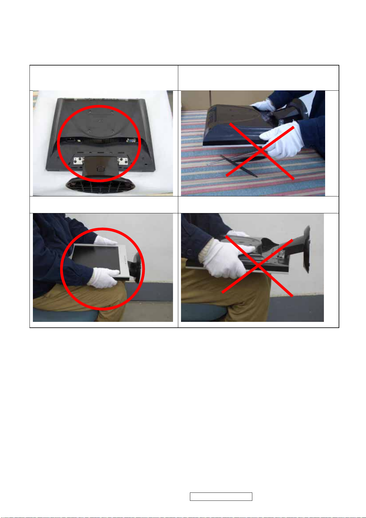
Place the monitor on a clean and soft foam
3
pad.
Place the monitor on the lap, the panel
surface must be upwards.
Placing the monitor on foreign objects. That
could scratch the surface of the panel or cause
“Mura.”
The panel is placed facedown on the lap. That
may cause “Mura.”
ViewSonic Corporation VA503b-1_ VA503m-1
Confidential - Do Not Copy
4
2. Specification
INTRODUCTION
FEATURES VA503b / VA503m
Size 15 “
Luminance (Typ)
Contrast Ratio (Typ) 500:1
1st TFT LCD panel
2nd TFT LCD panel
3rd TFT LCD panel
4th TFT LCD panel
Input Signal
Sync Compatibility
Compatibility
Power Voltage AC 100-240V, 50/60Hz Yes
Power Consumption
Ergonomics
OSD Control [ 1 ] [ 2 ] [ ][▼] [▲] Yes
Dimension
Weight
Operating Condition
Storage Condition
Regulation
ViewSonic Corporation VA503b-1_ VA503m-1
Colors 16.2 M colors (6+2bit panel)
Response Time (Typ) 12 ms
Viewing Angle (H/V) 120 ° / 100 °
Recommend resolution 1024 x 768 @60Hz
Size 15 “
Luminance (Typ)
Contrast Ratio (Typ) 500 :1
Colors 16.2 M colors (6+2bit panel)
Response Time (Typ) 12 ms
Viewing Angle (H/V) 140 ° / 120 °
Recommend resolution 1024 x 768 @60Hz
Size 15 “
Luminance (Typ)
Contrast Ratio (Typ) 500:1
Colors 16.2 M colors (6+2bit panel)
Response Time (Typ) 12 ms
Viewing Angle (H/V) 120 ° / 100 °
Recommend resolution 1024 x 768 @60Hz
Size 15 “
Luminance (Typ)
Contrast Ratio (Typ) 450:1
Colors 16.2 M colors (6+2bit panel)
Response Time (Typ) 16 ms
Viewing Angle (H/V) 120 ° / 100 °
Recommend resolution 1024 x 768 @60Hz
Analog (75ohms, 0.7/1.0 Vp-p) Yes
Digital (DVI-D) No
Separate Sync Yes
Composite Sync No
Sync on Green No
PC Yes
Power Mac Yes
TV Box (NextVision 6) Yes
On Mode(Max / Typ) Under 23 W in max
Active Off Mode (Max) Saving mode< 2W / Off mode <1 W
Tilt ( -5 ° - 22.5 °)
Swivel No
Pivot No
Height Adjust No
Physical (W x H x D) 344 x 347.5 x 147 (mm)
13.15 x 13.68 x 5.79 (in)
Package (W x H x D) 396 x 400 x 141 (mm)
Physical (Net Weight) 2.7 kg / 5.95 lbs
Package (Gross Weight) 3.7 kg / 8.16 lbs
Temperature (℉/℃) 32℉~104℉ / 0℃~40℃
Humidity (%) 20 % - 90 %
Temperature (℉/℃) -4℉~140℉ / -20℃~60℃
Humidity (%) 5 % - 90 %
CB / TCO99 / UL/cUL / FCC-B / ICES 003 / Argentina-TUV/S / NOM / EPA Energy Star /
TUV/Ergo / ISO134062 / TUV/GS / CE / GOST-R / SASO / BSMI / PSB / C-Tick / CCC / RoHS
/ WEEE
Confidential - Do Not Copy
250 cd/㎡
200 cd/㎡
250 cd/㎡
250 cd/㎡
Yes
15.59 x 15.75 x 5.55 (in
1 GENERAL specification
Test Resolution & Frequency 1024 x 768 @ 60Hz
Test Image Size Full Size
Contrast and Brightness Controls
Factory Default:
Contrast = 70%, Brightness = 100%
2 VIDEO INTERFACE
Analog Input Connector DB-15 (Analog), refer the appendix A
Default Input Connector Defaults to the first detected input
Video Cable Strain Relief
Equal to twice the weight of the monitor for five
minutes
Video Cable Connector DB-15 Pin out Compliant DDC 1/2B
Video Signals 1. Video RGB (Analog), Separate
Video Impedance 75 Ohms (Analog)
Maximum PC Video Signal 950 mV with no damage to monitor
Maximum Mac Video Signal 1250 mV with no damage to monitor
Sync Signals LVDS
DDC 1/2B Compliant with Revision 1.3
Sync Compatibility Separate Sync
Shall be compatible with all PC type computers,
Video Compatibility
Macintosh computers, and after market video
cards
Resolution Compatibility
640 x 350, 640 x 480, 720 x 400 (640 x 400),
800 x 600, 832 x 624, 1024 x 768
Exclusions Not compatible with interlaced video
3 POWER SUPPLY
Internal Power Supply Part Number: 715G1823-I
Input Voltage Range 100 TO 240 VAC
Input Frequency Range 50 TO 60 HERTZ
Short Circuit Protection Output can be shorted without damage
Over Current Protection (1)13V_4.5A@5V_1.5A
(2)5V_6A@13V_2A
Leakage Current 3.5 mA (Max) at 254VAC / 60Hz
Efficiency 80 % typical at 115VAC Full Load
Fuse Internal and not user replaceable
Power Dissipation 4 Watts (typ)
Max Input AC Current 1 Arms @ 90VAC, 0.5 Arms @180VAC
Inrush Current (Cold Start) 60 A @ 240 VAC, 30 A(max) @ 110 VAC
Shall start and function properly when under full load, with
Power Supply Cold Start
all combinations of input voltage, input frequency, and
operating temperature
Power Supply Transient Immunity
Power Supply Line Surge Immunity
Shall be able to withstand an ANSI/IEEE C62.41-1980
6000V 200 ampere ring wave transient test with no damage
Shall be able to withstand 1.5 times nominal line voltage
for one cycle with no damage
Shall be able to function properly, without reset or visible
Power Supply Missing Cycle Immunity
screen artifacts, when ½ cycle of AC power is randomly
missing at nominal input
Power Supply Acoustics
The power supply shall not produce audible noise that
would be detectable by the user. Audible shall define to be
ViewSonic Corporation VA503b-1_ VA503m-1
Confidential - Do Not Copy
5
in compliance with ISO 7779 (DIN EN27779:1991) Noise
measurements of machines acoustics. Power Switch noise
shall not be considered
US Type Power Cable Length = 1.8m. Connects to AC/DC Power Color = Black
Power Saving Operation(Method) VESA DPMS Signaling
Power Consumption
ON Mode < 23 W (max)
POWER SAVING < 2W ,OFF < 1W
Recovery Time On Mode = N/A, Active Off < 3 sec
4 ELECTRICAL REQUIREMENT
Horizontal / Vertical Frequency
Horizontal Frequency 30 – 62 KHZ
Vertical Refresh Rate 50 – 85 HZ.
Maximum Pixel Clock 80 MHz
Sync Polarity Independent of sync polarity.
Timing Table
Item Timing Analog
1 640 x 350 @ 70Hz, 31.5kHz
2 640 x 400 @ 70Hz
3 640 x 480 @ 50Hz
4 640 x 480 @ 60Hz, 31.5kHz
5 640 x 480 @ 67Hz, 35.0kHz
6 640 x 480 @ 72Hz, 37.9kHz
7 640 x 480 @ 75Hz, 37.5kHz
8 640 x 480 @ 85Hz, 43.27kHz
9 720 x 400 @ 70Hz, 31.5kHz
10 800 x 600 @ 56Hz, 35.1kHz
11 800 x 600 @ 60Hz, 37.9kHz
12 800 x 600 @ 72Hz, 48.1kHz
13 800 x 600 @ 75Hz, 46.9kHz
14 800 x 600 @ 85Hz, 53.7kHz
15 832 x 624 @ 75Hz, 49.7kHz
16 1024 x 768 @ 60Hz, 48.4kHz
17 1024 x 768 @ 70Hz, 56.5kHz
18 1024 x 768 @ 72Hz, 58.1kHz
19 1024 x 768 @ 75Hz, 60.0kHz
Yes
Yes
Yes
Yes
Yes
Yes
Yes
Yes
Yes
Yes
Yes
Yes
Yes
Yes
Yes
Yes
Yes
Yes
Yes
*1. Tolerance ≧ ± 2kHz.
*2. Any timing not in the list, it should display as normal or show on “OUT OF RANGE” OSD message
without blanking.
*3. The image quality of 85Hz mode might be worse than 75Hz.
AUDIO INTERFACE (SPEAKER SPECIFICATION) (For VA503m only)
Line input connection 3.5 mm stereo jack
Line input signal 1.0Vrms
Line input impedance >10 kOhm
Maximum power output (Electric) 1 W @ < 8% distortion
Signal to Noise Ratio 50 dB
Frequency response 500 Hz – 20 Khz
Distortion < 8 % THD (@1kHz)
ViewSonic Corporation VA503b-1_ VA503m-1
Confidential - Do Not Copy
6
Vibration
Screen image
There should be no audible vibration with volume at
100%. (Input signal within 1.0 Vrms)
There should be no affect on the screen image stability
under any conditions
Connector PC99 requirement Audio in Lime Green pantone # 577C
Cable type / length 3.5mm stereo cable / 1.8m length
Audio DPMS
Note: There is no guarantee <1 W power consumption in
Active Off mode, when the Audio Cable is connected
ViewSonic Corporation VA503b-1_ VA503m-1
Confidential - Do Not Copy
7
TFT LCD PANEL
1st Panel Source HSD 150MX17 A01
Type TN, LVDS
Active Size 304.1 mm (H) x 228.1mm (V)
Pixel Arrangement RGB Vertical Stripe
Pixel Pitch 0.297 mm
Glass Treatment Anti Glare (Hard coating 3H)
# of Backlights 2 CCFL edge-light
Backlight Life 30,000 Hours (Min)
Luminance –Condition: CT = 6500 K
Contrast = Max, Brightness = Max
250 cd/m2 (Typ after 30 minute warm up)
200 cd/m2 (Min after 30 minute warm up)
Brightness Uniformity 75 % (min)
Contrast Ratio 500 :1 (Typ), 400 :1 (Min)
Color Depth Vertical) 16.2 million colors (6+2 bit panel)
Viewing Angle (Horizontal)
Viewing Angle (Vertical)
Response Time
10%-90% @ Ta=25°C
120° (Typ)@ CR>10 / X° (Typ)@ CR>5
100° (Typ) @ CR>10 / X° (Typ)@ CR>5
12 ms (Tr= 8.5 ms, Tf = 3.5 ms) (Typ)
18 ms (Tr= 5 ms, Tf = 11 ms) (max)
Panel Defects Please see Panel Quality Specifications.
2nd Panel Source AUO, M150XN07 v3
Type TN, LVDS
Active Size 304.128 mm (H) x 228.096mm (V)
Pixel Arrangement RGB Vertical Stripe
Pixel Pitch 0.297 mm
Glass Treatment Anti Glare (Hard coating 3H)
# of Backlights 2 CCFL edge-light
Backlight Life 30,000 Hours (at 8.0mA)
Luminance –Condition: CT = 6500 K
Contrast = Max, Brightness = Max
200 cd/m2 (Typ after 30 minute warm up)
150 cd/m2 (Min after 30 minute warm up)
Brightness Uniformity 80%(typ) / 75 % (min)
Contrast Ratio 500 :1 (Typ), 400 :1 (Min)
Color Depth Vertical) 16.2 million colors (6+2 bit panel)
Viewing Angle (Horizontal) 140° (Typ)@ CR>10 / 140° (Typ)@ CR>5
Viewing Angle (Vertical) 120° (Typ) @ CR>10 / 130° (Typ)@ CR>5
Response Time
10%-90% @ Ta=25°C
12 ms (Tr= 8.5 ms, Tf = 3.5 ms) (Typ)
16 ms (Tr= 11 ms, Tf = 5 ms) (max)
Panel Defects Please see Panel Quality Specifications.
ViewSonic Corporation VA503b-1_ VA503m-1
Confidential - Do Not Copy
8
9
3rd Panel Source HSD 150MX17 A02
Type TN, LVDS
Active Size 304.1 mm (H) x 228.1mm (V)
Pixel Arrangement RGB Vertical Stripe
Pixel Pitch 0.297 mm
Glass Treatment Anti Glare (Hard coating 3H)
# of Backlights 2 CCFL edge-light
Backlight Life 30,000 Hours (Min)
Luminance –Condition: CT = 6500 K
Contrast = Max, Brightness = Max
250 cd/m2 (Typ after 30 minute warm up)
200 cd/m2 (Min after 30 minute warm up)
Brightness Uniformity 75 % (min)
Contrast Ratio 500 :1 (Typ), 400 :1 (Min)
Color Depth Vertical) 16.2 million colors (6+2 bit panel)
Viewing Angle (Horizontal)
Viewing Angle (Vertical)
Response Time
10%-90% @ Ta=25°C
120° (Typ)@ CR>10 / X° (Typ)@ CR>5
100° (Typ) @ CR>10 / X° (Typ)@ CR>5
12 ms (Tr= 8.5 ms, Tf = 3.5 ms) (Typ)
18 ms (Tr= 5 ms, Tf = 11 ms) (max)
Panel Defects Please see Panel Quality Specifications.
4th Panel Source SVA 150XG04TB
Type TN, LVDS
Active Size 304.1 mm (H) x 228.1mm (V)
Pixel Arrangement RGB Vertical Stripe
Pixel Pitch 0.297 mm
Glass Treatment Anti Glare (Hard coating 3H)
# of Backlights 2 CCFL edge-light
Backlight Life 30,000 Hours (Min)
Luminance –Condition: CT = 6500 K
Contrast = Max, Brightness = Max
250 cd/m2 (Typ after 30 minute warm up)
200 cd/m2 (Min after 30 minute warm up)
Brightness Uniformity 75 % (min)
Contrast Ratio 450 :1 (Typ), 350 :1 (Min)
Color Depth Vertical) 16.2 million colors (6+2 bit panel)
Viewing Angle (Horizontal)
Viewing Angle (Vertical)
Response Time
10%-90% @ Ta=25°C
120° (Typ)@ CR>10 / X° (Typ)@ CR>5
100° (Typ) @ CR>10 / X° (Typ)@ CR>5
16 ms (Tr= 4 ms, Tf = 12 ms) (Typ)
25 ms (Tr= 7 ms, Tf = 18 ms) (max)
Panel Defects Please see Panel Quality Specifications.
ViewSonic Corporation VA503b-1_ VA503m-1
Confidential - Do Not Copy
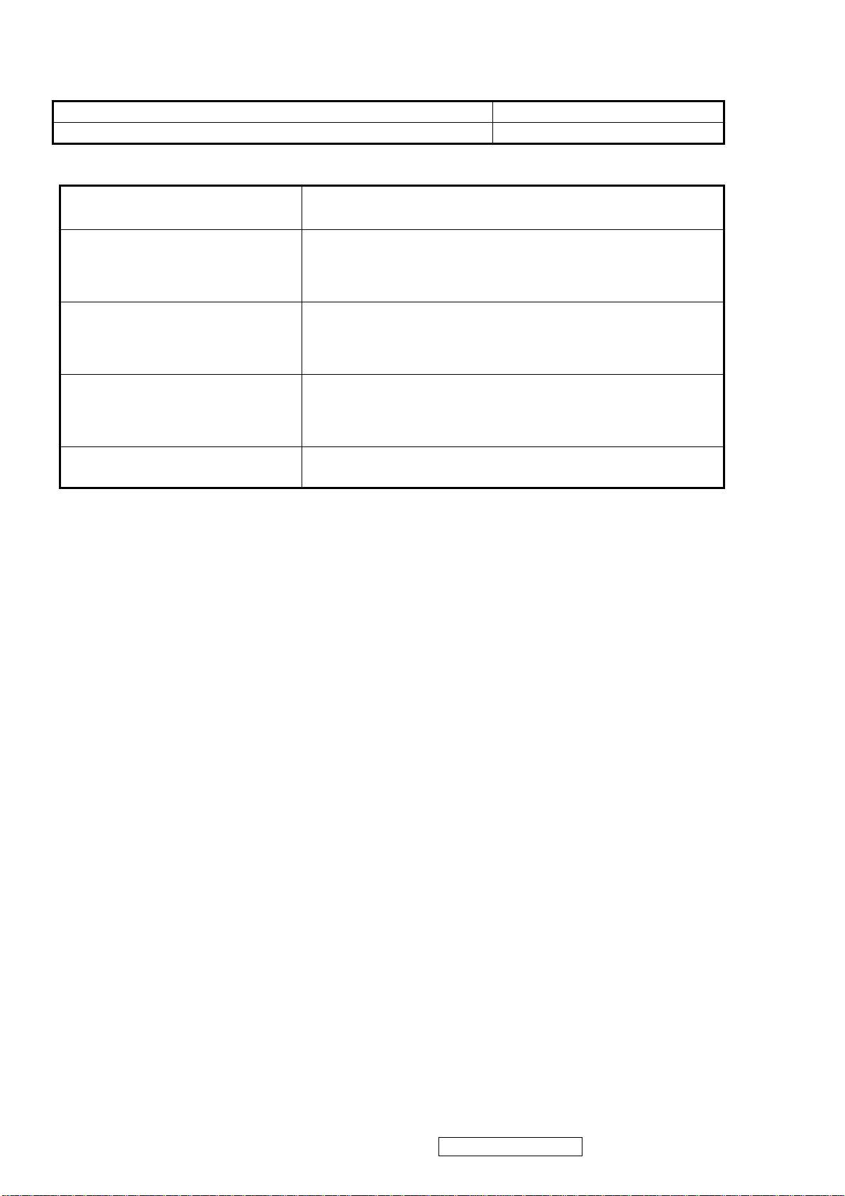
IMAGE PERFORMANCE
Display Size
Horizontal Display Size, Primary Preset Full Screen
Vertical Display Size, Primary Preset Full Screen
Preset Color Temperatures
sRGB
It should meet IEC 61966-2-1 (1999-10) standard.
Preset 1(9300K)
CCT(Max) = 10250K
CCT(Min) = 8500K
Preset 2 (Primary)(6500K)
CCT(Max) = 7595K
CCT(Min) = 5930K
Preset 3(5400K)
CCT(Max) = 5830K
CCT(Min) = 4860K
Preset Color Temperature
CCT (typ) = 9300K (u’CCT=0.1888; v’ CCT=0.4457)
CCT (max) = 10250K, CCT (min) = 8500K
Δu’v’<0.01 (@ Full White pattern)
CCT (typ) = 6500K (u’CCT=0.1978; v’ CCT=0.4684)
CCT (max) = 7595K, CCT (min) = 5930K
Δu’v’<0.01 (@ Full White pattern)
CCT (typ) = 5400K (u’CCT=0.2044; v’ CCT=0.4808)
CCT (max) = 5830K, CCT (min) = 4860K
Δu’v’<0.01 (@ Full White pattern)
Each color preset shall be adjustable. Red, Green, and Blue
shall be individually controlled.
Video Cards Compatibility
Peaking Performance: Peaking is not adjustable
Raster Artifacts
● Video Artifacts : No visible streaking, sag, or smearing artifacts when driven by the specified video
cards in the primary mode and after user adjustment to best condition
● Power Supply, and Grounding Artifacts : No visible artifacts in any specified video mode within the
horizontal or vertical frequency range of the monitor
Temperature Drift : Image shall not drift or lose fine-tune adjustment
ViewSonic Corporation VA503b-1_ VA503m-1
Confidential - Do Not Copy
10
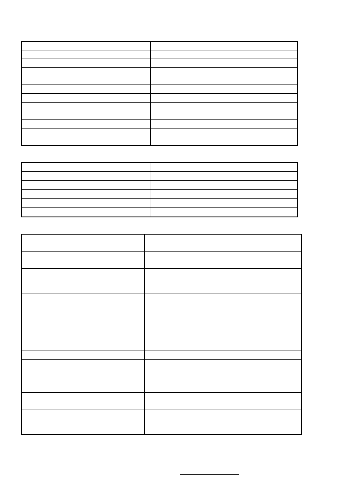
MECHANICAL
Dimension
Dimension (Desktop) 344mm(W)*347.5mm(H)*147mm(D)
Width 344mm
Height (Height adjust to the bottom) 347.5mm
Depth 147mm
Monitor Weight 2.7Kg(N/W); 3.7Kg(G/W)
*Refer to Figure 1
Dimension (Head Only / Wall Mount) 344mm (W)*290mm(H)*54mm(D)
Width 344mm
Height 290mm
Depth 54mm
Monitor Weight 2.4Kg
*Refer to Figure 1
Ergonomics
Tilt Up step 1 0° to 20°±2.5°
Tilt Down N/A
Swivel Right N/A
Swivel Left N/A
Height Adjust N/A
Pivot N/A
Cabinet Material
Display Head Plastic Material Samsung starex ABS SD-0150 (94HB)
Neck/Base Plastic Material Samsung starex ABS SD-0150 (94HB)
Internal Plastic Cabinet Components
All internal plastic cabinet components shall be in
compliance with the requirements of TCO99
The reference for the bezel is the silver color
Front Bezel Color
(VA503m) and the midnight gray color (VA503b)
chip provided by ViewSonic
The reference for the bezel is the black color
(VA503m) and the midnight gray color
(VA503b) chip provided by ViewSonic.
Neck, Base, and Rear Cover Color
The color difference between any two cabinet
components shall be less than 0.80 “Delta E”,
in the 1976 CIE L*a*b Colorspace.
Rear logo color Mold type
The color drift due to UV-Light shall be less than 3.0
Cabinet Color Drift Due To UV-Light
“Delta E” in the 1976 CIE L*a*b colorspace.
Testing shall be performed according to the
requirements of ASTM Test Method D4459-93.
Cabinet Texture
Mold-Tech # 11010 used on all external textured
surfaces.
The supplier shall submit textured color chips, plastic
Samples
material specifications, and Material Safety Data
Sheets for approval.
ViewSonic Corporation VA503b-1_ VA503m-1
Confidential - Do Not Copy
11
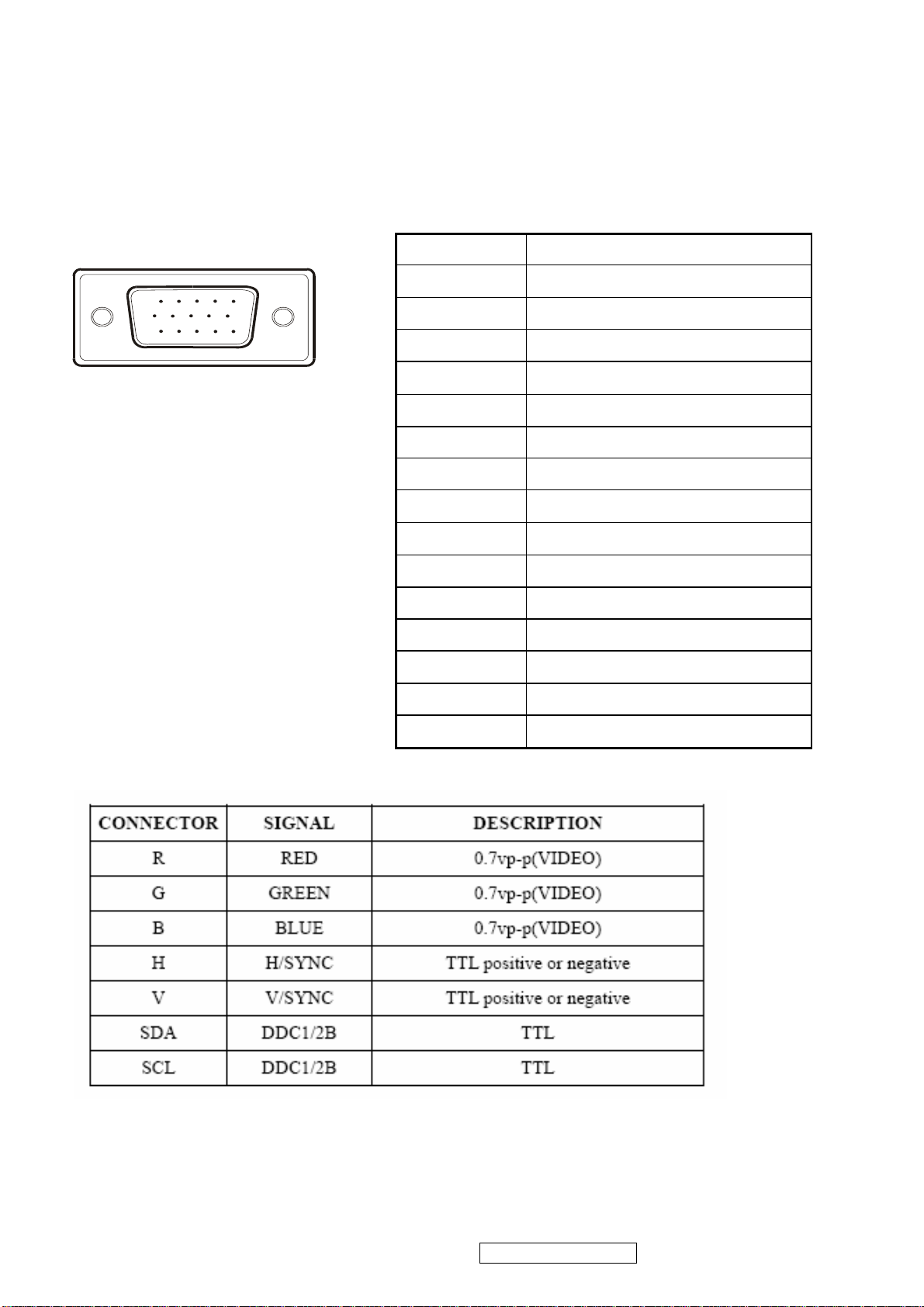
INTERFACE DESCRIPTION
D-SUB 15 PIN CONNECTOR
15
6
11 15
10
SIGNAL LEVEL
Pin Number Pin Function
1 Red video input
2 Green video input
3 Blue video input
4 No Connection
5 Ground
6 Red video ground
7 Green video ground
8 Blue video ground
9 +5V
10 H/V sync ground
11 No connection
12 (SDA)
13 Horizontal sync (Composite sync)
14 Vertical sync
15 (SCL)
ViewSonic Corporation VA503b-1_ VA503m-1
Confidential - Do Not Copy
12
3. Front Panel Function Control Description
ViewSonic Corporation VA503b-1_ VA503m-1
Confidential - Do Not Copy
13
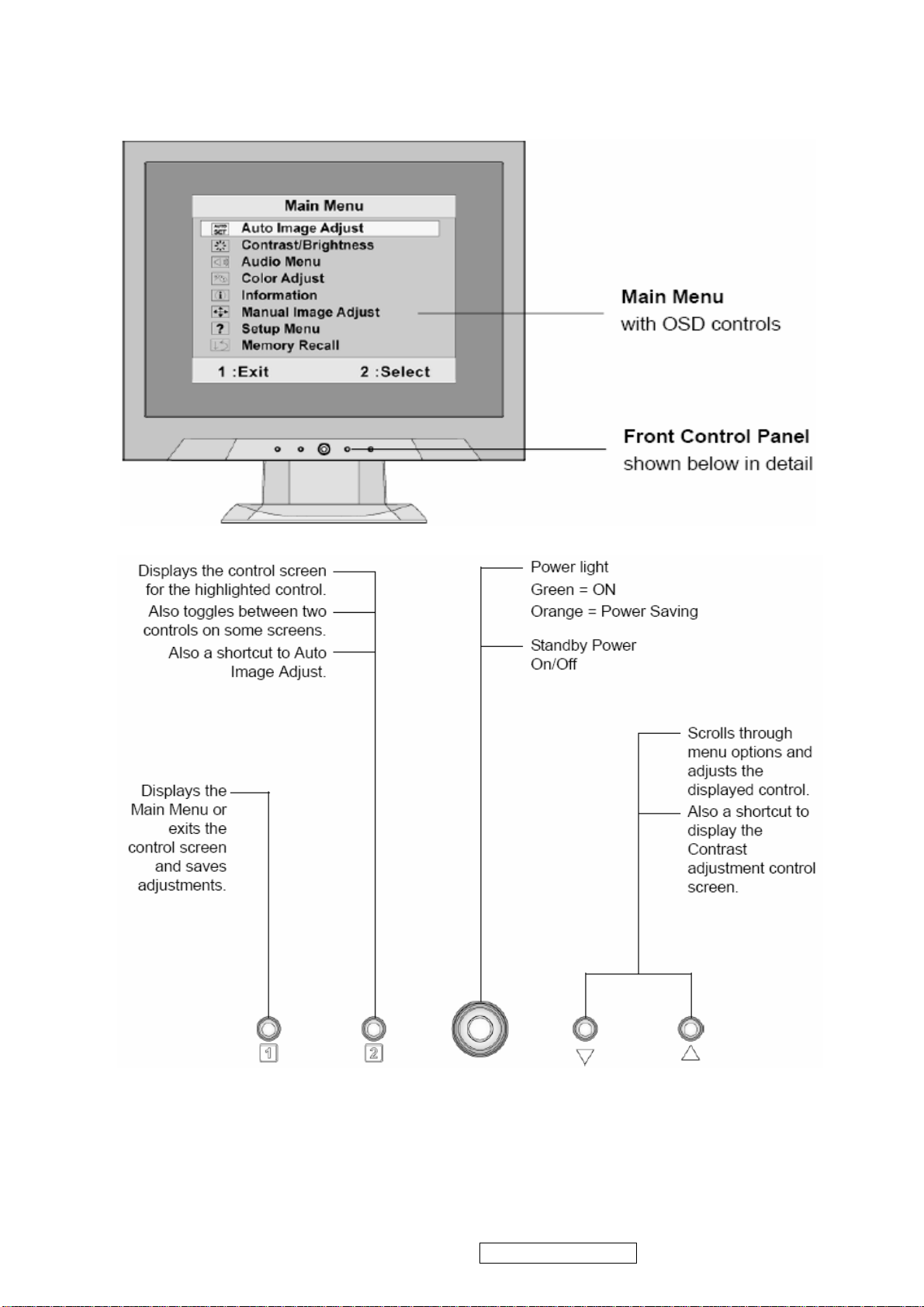
Do the following to adjust the display setting:
1. To display the Main Menu, press button [1].
NOTE: All OSD menus and adjustment screens disappear automatically after about 15
seconds. This is adjustable through the OSD timeout setting in the setup menu.
2. To select a control to adjust, press ▲or ▼ to scroll up or down in the Main Menu.
3. After the desired control is selected, press button [2]. A control screen like the one
shown below appears.
The line at the bottom of the screen shows the
current functions of buttons 1 and 2: Exit or
select the Brightness control.
4. To adjust the control, press the up ▲ or▼ down T buttons.
5. To save the adjustments and exit the menu, press button [1] twice.
The following tips may help you optimize your display:
• Adjust the computer's graphics card so that it outputs a 1024 x 768 @ 60Hz video
signal to the LCD display. (Look for instructions on “changing the refresh rate” in the
graphics card's user guide.)
• If necessary, make small adjustments using H. POSITION and V. POSITION until the
screen image is completely visible
. (The black border around the edge of the screen
should barely touch the illuminated “active area” of the LCD display.)
ViewSonic Corporation VA503b-1_ VA503m-1
Confidential - Do Not Copy
14
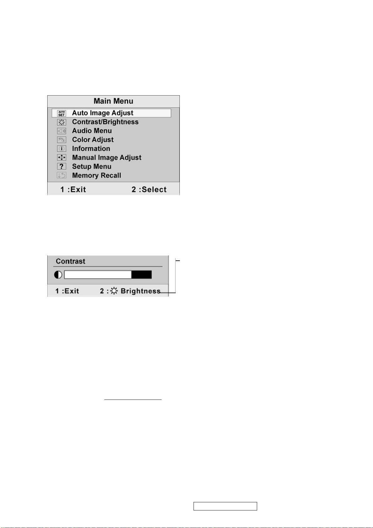
Main Menu Controls
Adjust the menu items shown below by using the up S and down T buttons.
Control Explanation
Auto Image Adjust automatically sizes, centers, and fine tunes the video signal
to eliminate waviness and distortion. Press the [2] button to obtain a sharper
image.
NOTE: Auto Image Adjust works with most common video cards. If this
function does not work on your LCD display, then lower the video refresh rate
to 60 Hz and set the resolution to its pre-set value.
Contrast adjusts the difference between the image background (black level)
and the foreground (white level).
Brightness adjusts background black level of the screen image.
Audio Adjust(For VA503m only)
Volume increases the volume, decreases the volume, and mutes the audio.
Mute temporarily silences audio output.
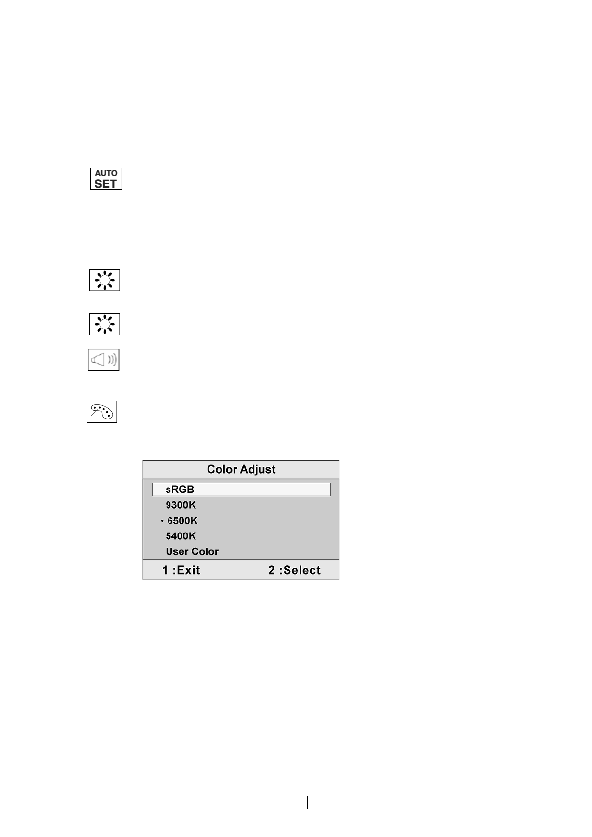
Color Adjust provides several color adjustment modes, including preset color
temperatures and a User Color mode which allows independent adjustment of
red (R), green (G), and blue (B). The factory setting for this product is 6500K
(6500 Kelvin).
sRGB-This is quickly becoming the industry standard for color management,
with support being included in many of the latest applications. Enabling this
setting allows the LCD display to more accurately display colors the way they
were originally intended. Enabling the sRGB setting will cause the Contrast and
Brightness adjustments to be disabled.
9300K-Adds blue to the screen image for cooler white (used in most office
settings with fluorescent lighting).
6500K-Adds red to the screen image for warmer white and richer red.
5400K-Adds green to the screen image for a darker color.
ViewSonic Corporation VA503b-1_ VA503m-1
Confidential - Do Not Copy
15
Control Explanation
User Color Individual adjustments for red (R), green (G), and blue (B).
1. To select color (R, G or B) press button [2].
2. To adjust selected color, pressSandT.
Important: If you select RECALL from the Main Menu when the product is
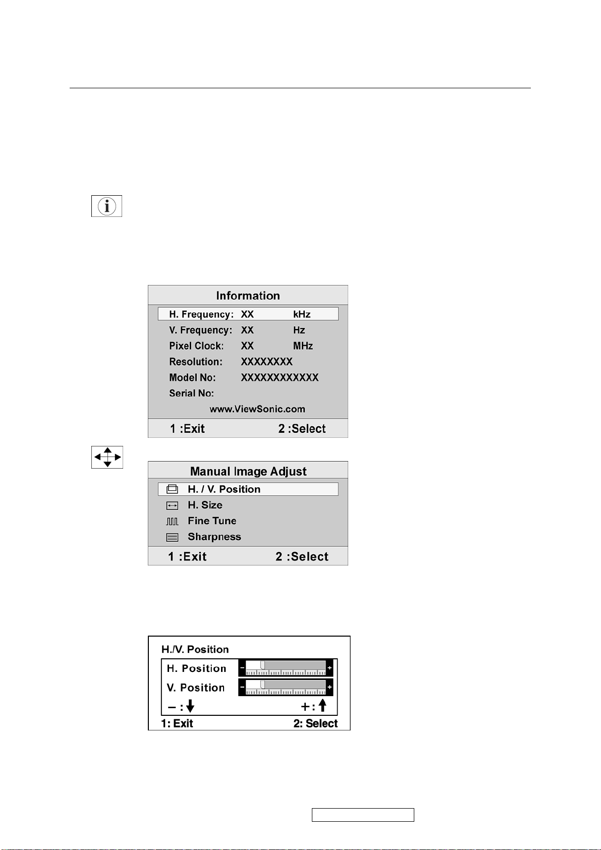
set to a Preset Timing Mode, colors return to the 6500K factory preset.
Information displays the timing mode (video signal input) coming from the
graphics card in the computer, the LCD model number, the serial number, and
the ViewSonic® website URL. See your graphics card’s user guide for
instructions on changing the resolution and refresh rate (vertical frequency).
NOTE: VESA 1024 x 768 @ 60Hz (recommended) means that the resolution is
1024 x 768 and the refresh rate is 60 Hertz.
Manual Image Adjust displays the Manual Image Adjust menu.
H. Size (Horizontal Size) adjusts the width of the screen image.
H./V. Position (Horizontal/Vertical Position) moves the screen image left or
right and up or down.
ViewSonic Corporation VA503b-1_ VA503m-1
Confidential - Do Not Copy
16
Control Explanation
Fine Tune sharpens the focus by aligning text and/or graphics with pixel
boundaries.
NOTE: Try Auto Image Adjust first.
Sharpness adjusts the clarity and focus of the screen image.
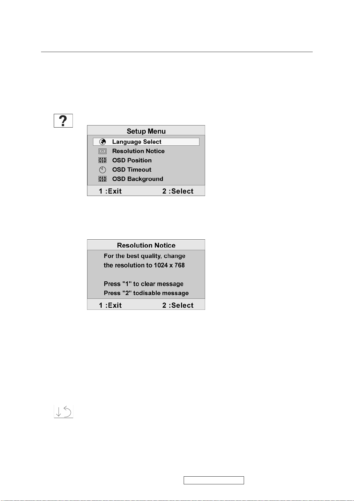
Setup Menu displays the menu shown below:
Language Select allows the user to choose the language used in the menus and
control screens.
Resolution Notice displays the Resolution Notice menu shown below.
Resolution Notice advises the optimal resolution to use.
OSD Position allows the user to move the OSD menus and control screens.
OSD Timeout sets the length of time the OSD screen is displayed. For example,
with a “15 second” setting, if a control is not pushed within 15 seconds, the
display screen disappears.
OSD Background allows the user to turn the OSD background On or Off.
Memory Recall returns the adjustments back to factory settings if the display is
operating in a factory Preset Timing Mode listed in the Specifications of this
manual.
Exception: This control does not affect changes made with the User Color
control, Language Select or Power Lock setting.
ViewSonic Corporation VA503b-1_ VA503m-1
Confidential - Do Not Copy
17
SHORT CUTS FUNCTION FROM THE BUTTONS
[1]
Main Menu
[2]
[▼] or [▲]
[▼] + [▲]
[1] + [2]
[1] + [▼] + [▲]
(keep pushing 5 sec)
[1] + [▼]
[1] + [▲]
Auto Image Adjust
To immediately activate Contrast menu. It should be
change to Brightness OSD by push button [2]
recall both of Contrast and Brightness to default
toggle 720x400 and 640x400 mode when input 720x400
or 640x400 mode
White Balance (Not shown on user’s guide)
Power Lock
OSD Lock
Remark : All the short cuts function are only available while OSD off
ViewSonic Corporation VA503b-1_ VA503m-1
Confidential - Do Not Copy
18

4. Circuit Description
4.1 LCD MONITOR DESCRIPTION
The LCD MONITOR will contain a Main Board, an Power Board, Key Board which
house the flat panel control logic, brightness control logic and DDC.
Monitor Block Diagram
Power Board
(Include: adapter, inverter)
AC-IN
100V-240V
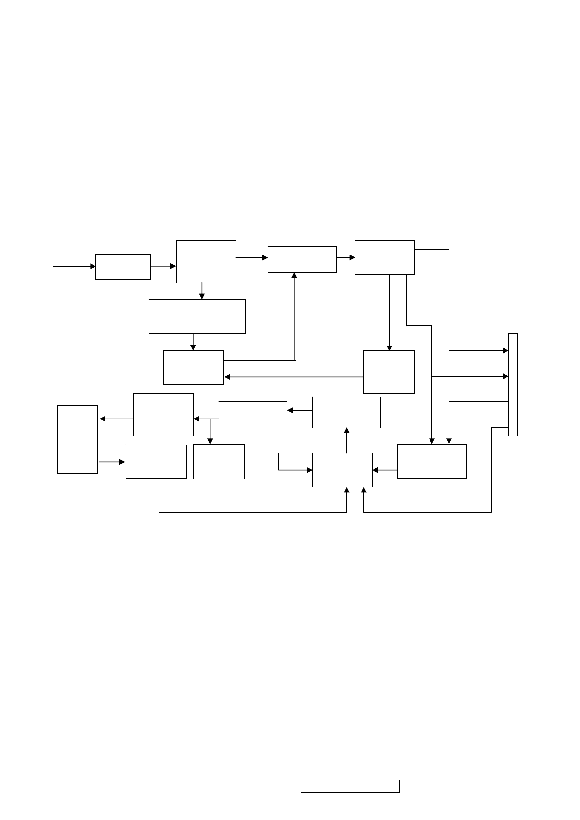
4.2 MAIN BOARD BLOCK FUNCTION DESCRIPTION
The main board contains panel control logic, brightness control logic, DDC and DC
convert DC circuit and so on.
R
G
B
H
V
SDA
SCL
CCFL Drive.
Main Board
Key Board
EPROM EPROM
Flat Panel and
CCFL backlight
HOST Computer
PWPC board
TSUM16AK
OSC
RS232 Connector
For white balance
adjustment in factory
mode
Video signal, DDC
Backlight and Panel
Keyboard
ViewSonic Corporation VA503b-1_ VA503m-1
Confidential - Do Not Copy
19
4.3 PWPC BOARD BLOCK FUNCTION DESCRIPTION
PWPC board combines to adapter and inverter, Adapter which commonly consists
of bridge rectifier and filter, start circuit, PWM control circuit, protection circuits and
convert to 12V, 5V DC voltage by input 90V-240V AC voltage that provide power supply
for each chips in the main board and inverter. Inverter is DC TO AC circuit. It changes
the 12v DC of power supply to about 600-800v AC that drives the backlight. It mostly
consists of starting circuit, PWM controller, DC changing circuit, LC surging circuit,
output circuit and protection circuit etc.
AC input
EMI filter
Bridge
Rectifier
and Filter
Transformer
Rectifier
CMOS
St art Circuit
R903, R904,R905
5V
Lamp
OSC and
Output
Circuit
Feedback
Circuit
PWM
Control IC
Over
Voltage
DC Convert
Circuit
MOSFET
Q203
PWM
Control IC
Over
Voltage
Protect
12V
ON/OF
ON/OFF
Control
DIM
CN902
ViewSonic Corporation VA503b-1_ VA503m-1
Confidential - Do Not Copy
20

4.4 INTRODUCTION OF IC
STUM16AK(U401): integrate ADC, OSD, SCALER, MCU, LVDS, convert analog RGB
into digital and room and shrink scaling output to LCD panel.
PIN Function:
Pin Symbol Description
70 SDO SPI flash serial data output; Input w/5V-tolerant
71 CSZ SPI flash chip select; output
72 SCK SPI flash serial select; output
73 SDI SPI flash serial data input; output
65 DDCA_SDA/RS232_TX DDC data for analog interface; 4mA driving
strength/UART transmitter/GPIO; I/O w/5V-tolrant
66 DDCA_SDA/RS232_RX DDC data for analog interface/UART
transmitter/GPIO;Input w/5V-tolrant
19 RST Chip reset; High reset; Input w/5V-tolerant
22 RSTN Chip reset; Low reset; Input w/5W-toerant
11 VCTRL Regulator control; Output
63 HSYNCO Analog HSYNC input
64 VSYNCO Analog VSYNC input
62 REFP Internal ADC top de-coupling pin
61 REFM Internal ADC bottom de-coupling pin
51 REXT
External resistor 390 ohm to AVDD_ADC
21 PWM1 PWM1; 4mA driving strength; Output
29 PWM0 PWM0; 4mA driving strength; Output
4 BYPASS For External Bypass Capacitor
32 XIN Xin; Crystal Oscillator Input
33 XOUT Xout; Crystal Oscillator Output
44、50、60 AVDD_ADC
52
34
14、67、95、
103、115
12、68、97、
AVDD_PLL
AVDD_MPLL
VDDP Digital Output Power 3.3V
VDDC Digital Core Power 1.8V
ADC Power 3.3V
PLL Power 3.3V
MPLL Power 3.3V
117
AIC1084-33PM (U702): DC power convert, used to 5v convert 3.3v.
LT1117-18(U701): DC power convert, used to 5v convert 3.3v.
TPA3003D2 (U601): The TPA3003D2 is a audio amplifier IC,3-W efficient, driving
speakers as low as 8
, range of gain from -40dB to 36 dB. The function of
each pin and the inside circuit diagram are as follows:
ViewSonic Corporation VA503b-1_ VA503m-1
Confidential - Do Not Copy
21
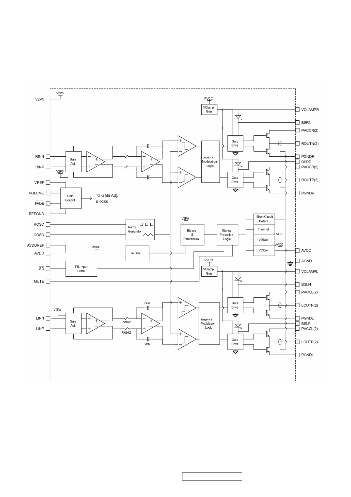
Circuit Diagram
ViewSonic Corporation VA503b-1_ VA503m-1
Confidential - Do Not Copy
22
PIN Function
TERMINAL
NO. NAME
I/O DESCRIPTION
AGND 9,10,26 AVcc 33 AVDD 29 O
AVDDREF 7 O
BSLN 13 I/O
BSLP 24 I/O
BSRN 48 I/O
BSRP 37 I/O
COSC 28 I/O
FADE 30 I
LINN 6 I
LINP 5 I
LOUTN 16,17 O
LOUTP 20,21 O
MUTE 34 I
NC 31,32,35 PGNDL 18,19 PGNDR 42,43 -
PVVCCL 14,15 PVVCCL 22,23 PVCCR 38,39 PVCCR 46,47 REFGND 12 -
RINP 3 I
RINN 2 I
ROSC 27 I/O
ROUTN 44,45 O
ROUTP 40,41 O
SD 1 I
VCLAMPL 25 VCLAMPR 36 VOLUME 11 I
VREF 8 I
V2P5 4 O
Analog gr ound for digital/analog cells in core
High-voltage analog power supply (8.5V to 14V)
5-V Regulated output
5-V Reference output-provided for connection to adjacent VREF terminal.
Bootstrap I/O for left channel, negative high-side FET
Bootstrap I/O for left channel, positive high-side FET
Bootstrap I/O for right channel, negative high-side FET
Bootstrap I/O for right channel, positive high-side FET
I/O for charge/discharging currents onto capacitor for ramp generator triangle wave
biased at V 2P 5
Input for controlling volume ramp rate when cycling SD or during power-up. A logic
low on this pin places the amplifier in fade mode. A logic
high on this pin allows a quick transition to the desired volume setting.
Negative differential audio input for left channel
Positive differential audio input for left channel
Class-D 1/2-H-bridge negative output for left channel
Class-D 1/2-H-bridge positive output for left channel
A logic high on this pin disables the outputs. A low on this pin enables the outputs.
Not internally connected
Power ground for left channel H-bridge
Power ground for right channel H-bridge
Power supply for left channel H-bridge(tied to pins 22 and 23 internally), not
connected to PVCCR or AVcc
Power supply for left channel H-bridge(tied to pins 14 and 15 internally), not
connected to PVCCR or AVcc
Power supply for right channel H-bridge(tied to pins 46 and 47 internally), not
connected to PVCCL or AVcc
Power supply for right channel H-bridge(tied to pins 38 and 39 internally), not
connected to PVCCL or AVcc
Ground for gain control circuitry. Connect to AGND. If using a DAC to control the
volume, connect the DAC ground to this terminal.
Positive differential audio input for right channel
Negative differential audio input for right channel
Current setting resistor for ramp generator. Nominally equal to 1/8*Vcc
Class-D 1/2-H-bridge negative output for right channel
Class-D 1/2-H-bridge positive output for right channel
Shutdown signal for IC (low=shutdown, high=operational). TTL logic levels with
compliance to Vcc.
Internally generated voltage supply for left channel bootstrap capacitors.
Internally generated voltage supply for right channel bootstrap capacitors.
DC voltage that sets the gain of the amplifier.
Analog reference for gain control section.
2.5-V Reference for analog cells, as well as reference for unused audio input when
using single-ended inputs.
ViewSonic Corporation VA503b-1_ VA503m-1
Confidential - Do Not Copy
23
 Loading...