

ViewSonic Q9-1, Q9b-1, VS10863-1W Service manual
Service Manual
ViewSonic Q9-1
Q9b-1
Model No. VS10863-1W
19” Color TFT LCD Display
(Q9-1_Q9b-1_SM Rev. 1a Dec. 2005)
ViewSonic 381 Brea Canyon Road, Walnut, California 91789 USA - (800) 888-8583
Copyright
Copyright © 2005 by ViewSonic Corporation. All rights reserved. No part of this publication may be
reproduced, transmitted, transcribed, stored in a retrieval system, or translated into any language or
computer language, in any form or by any means, electronic, mechanical, magnetic, optical, chemical,
manual or otherwise, without the prior written permission of ViewSonic Corporation.
Disclai mer
ViewSonic makes no representations or warranties, either expressed or implied, with respect to the
contents hereof and specifically disclaims any warranty of merchantability or fitness for any particular
purpose. Further, ViewSonic reserves the right to revise this publication and to make changes from time
to time in the contents hereof without obligation of ViewSonic to notify any person of such revision or
changes.
Trademarks
Optiquest is a registered trademark of ViewSonic Corporation.
ViewSonic is a registered trademark of ViewSonic Corporation.
All other trademarks used within this document are the property of their respective owners.
Revision History
Revision SM Editing Date ECR Number
1a 12/19/2005 Initial release Jamie Chang
Description of Changes Editor
Viewsonic Corporation i Confidential - Do Not Copy Q9-1_Q9b-1
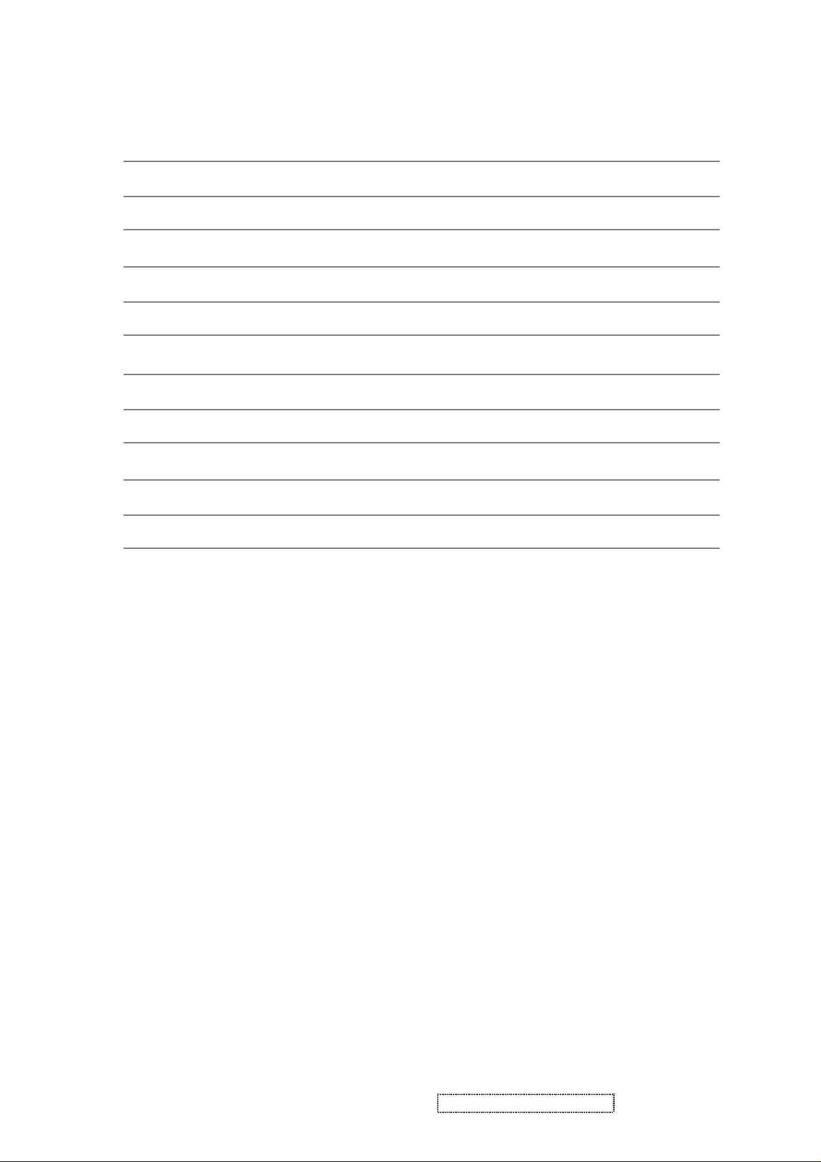
TABLE OF CONTENTS
1. Precautions and Safety Notices
2. Specification
3. Front Panel Function Control Description
4. Circuit Description
5. Adjusting Procedure
6. Trouble Shooting Flow Chart
7. Recommended Spare Parts List
8. Exploded View And Exploded Parts List
9. Block Diagram
10. Schematic Diagrams
11. PCB Layout Diagrams
1
5
8
14
20
34
38
42
44
45
49
Viewsonic Corporation ii Confidential - Do Not Copy Q9-1_Q9b-1

1. Precautions and Safety Notices
1-1. Appropriate Operation
(1) Turn off the product before cleaning.
(2) Use only a dry soft cloth when cleaning the LCD panel surface.
(3) Use a soft cloth soaked with mild detergent to clean the display housing.
(4) Use only high quality and safety approved AC/DC power adapter.
(5) Disconnect the power plug from AC outlet if the product is not used for a long period of time.
(6) If smoke, abnormal noise or strange odor is present, immediately switch the LCD display off.
(7) Do not touch the LCD panel surface with sharp or hard objects.
(8) Do not place heavy objects on the LCD display, video cable, or power cord.
(9) Do not use abrasive cleaners, waxes or solvents for your cleaning.
(10) Do not operate the product under the following conditions:
- Extremely hot, cold or humid environment.
- Areas susceptible to excessive dusts and dirt.
- Near any appliance generating a strong magnetic field.
- Place in direct sunlight.
1-2. Caution
No modification of any circuit should be attempted. Service work should only be performed after you are
thoroughly familiar with all of the following safety checks and servicing guidelines.
1-3. Safety Check
Care should be taken while servicing this LCD display. Because of the high voltage used in the inverter circuit,
the voltage is exposed in such areas as the associated transformer circuits.
1-4. Power Supply Requirements
The external power converter for this display utilizes AC and DC cords, AC cord is detachable, but DC cord is
permanently attached. Any attempt to replace another adapter could result in serious problem on the
display.
ViewSonic Corporation Confidential
1
-
Do Not Copy Q9-1_Q9b-1

1-5. LCD Module Handling Precautions
1-5.1 Handling Precautions
(1) Since front polarizer is easily damaged, pay attention not to scratch it.
(2) Be sure to turn off power supply when inserting or disconnecting from input connector.
(3) Wipe off water drop immediately. Long contact with water may cause discoloration or spots.
(4) When the panel surface is soiled, wipe it with absorbent cotton or other soft cloth.
(5) Since the panel is made of glass, it may break or crack if dropped or bumped on hard surface.
(6) Since CMOS LSI is used in this module, take care of static electricity and insure human earth when handling.
(7) Do not open nor modify the Module Assembly.
(8) Do not press the reflector sheet at the back of the module to any directions.
(9) In case if a Module has to be put back into the packing container slot after once it was taken out from the
container, do not press the center of the CCFL Reflector edge. Instead, press at the far ends of the CFL
Reflector edge softly. Otherwise the TFT Module may be damaged.
(10) At the insertion or removal of the Signal Interface Connector, be sure not to rotate nor tilt the Interface
Connector of the TFT Module.
(11) After installation of the TFT Module into an enclosure (LCD monitor housing, for example), do not twist nor
bend the TFT Module even momentary. At designing the enclosure, it should be taken into consideration
that no bending/twisting forces are applied to the TFT Module from outside. Otherwise the TFT Module
may be damaged.
(12) Cold cathode fluorescent lamp in LCD contains a small amount of mercury. Please follow local ordinances
or regulations for disposal.
(13) Small amount of materials having no flammability grade is used in the LCD module. The LCD module
should be supplied by power complied with requirements of Limited Power Source (IEC60950 or UL1950),
or be applied exemption.
(14) The LCD module is designed so that the CFL in it is supplied by Limited Current Circuit (IEC60950 or
UL1950). Do not connect the CFL in Hazardous Voltage Circuit.
ViewSonic Corporation Confidential
2
-
Do Not Copy Q9-1_Q9b-1
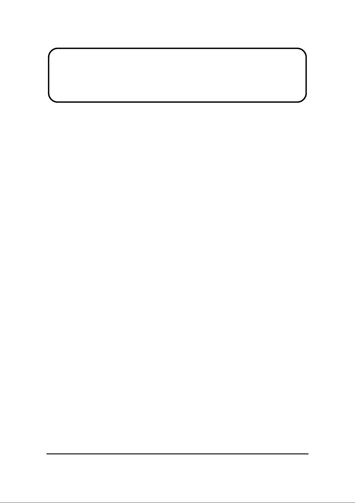
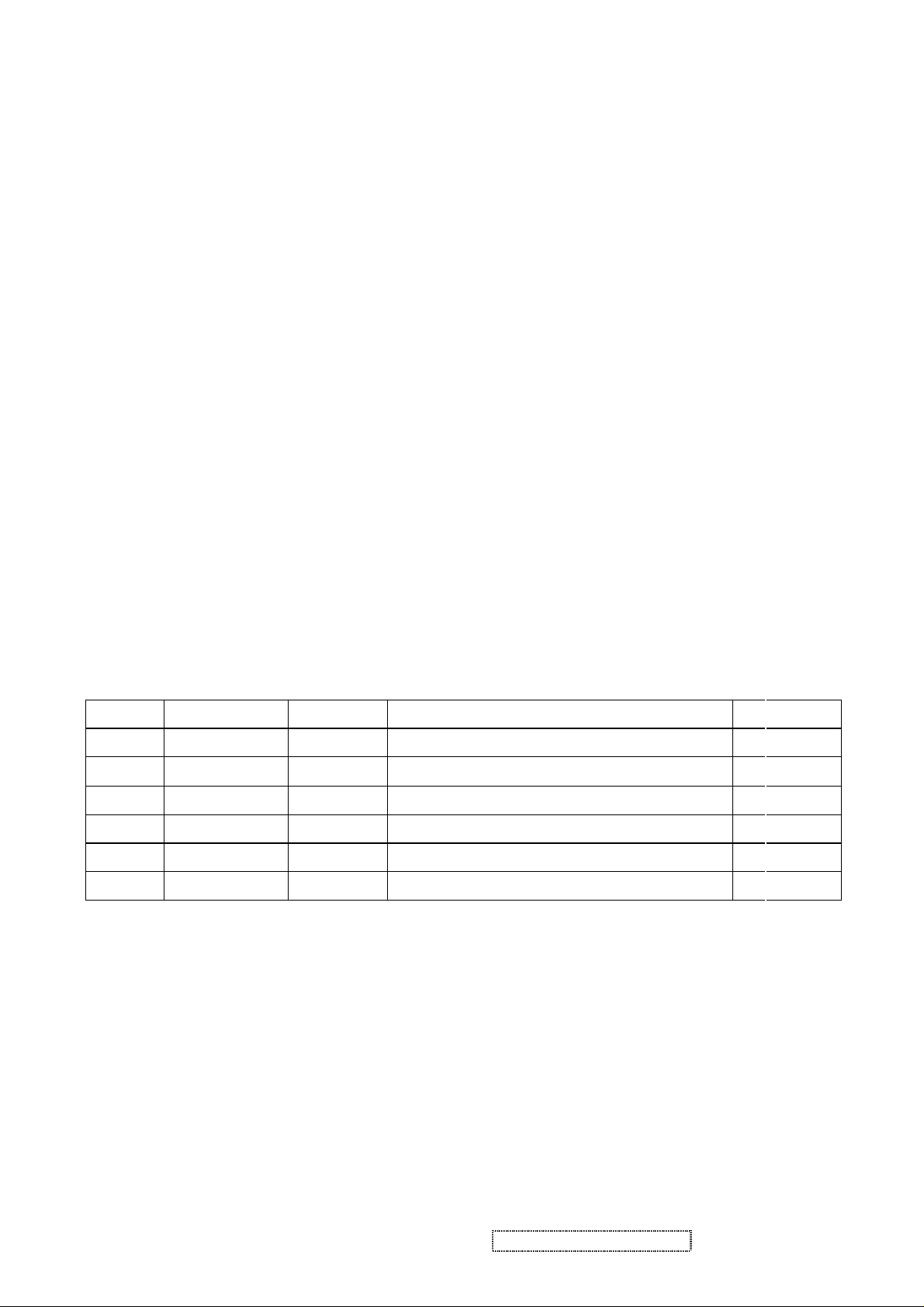
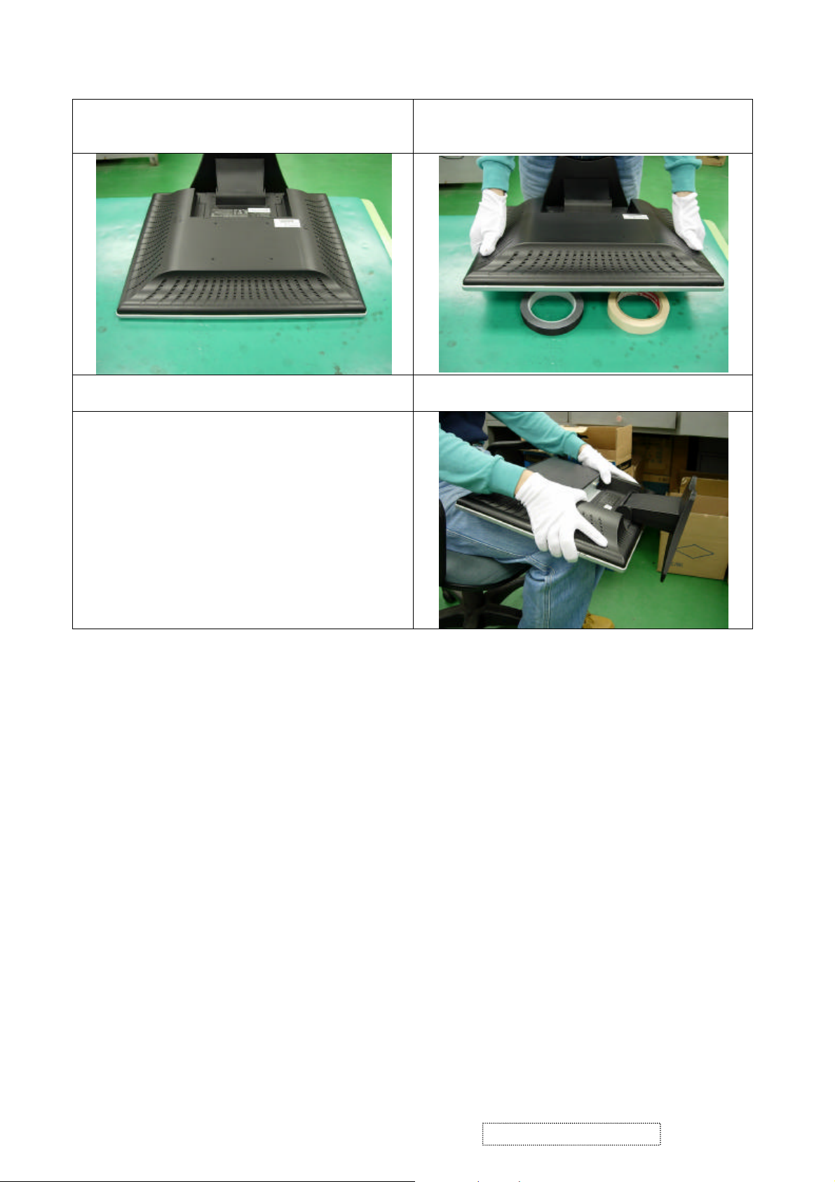
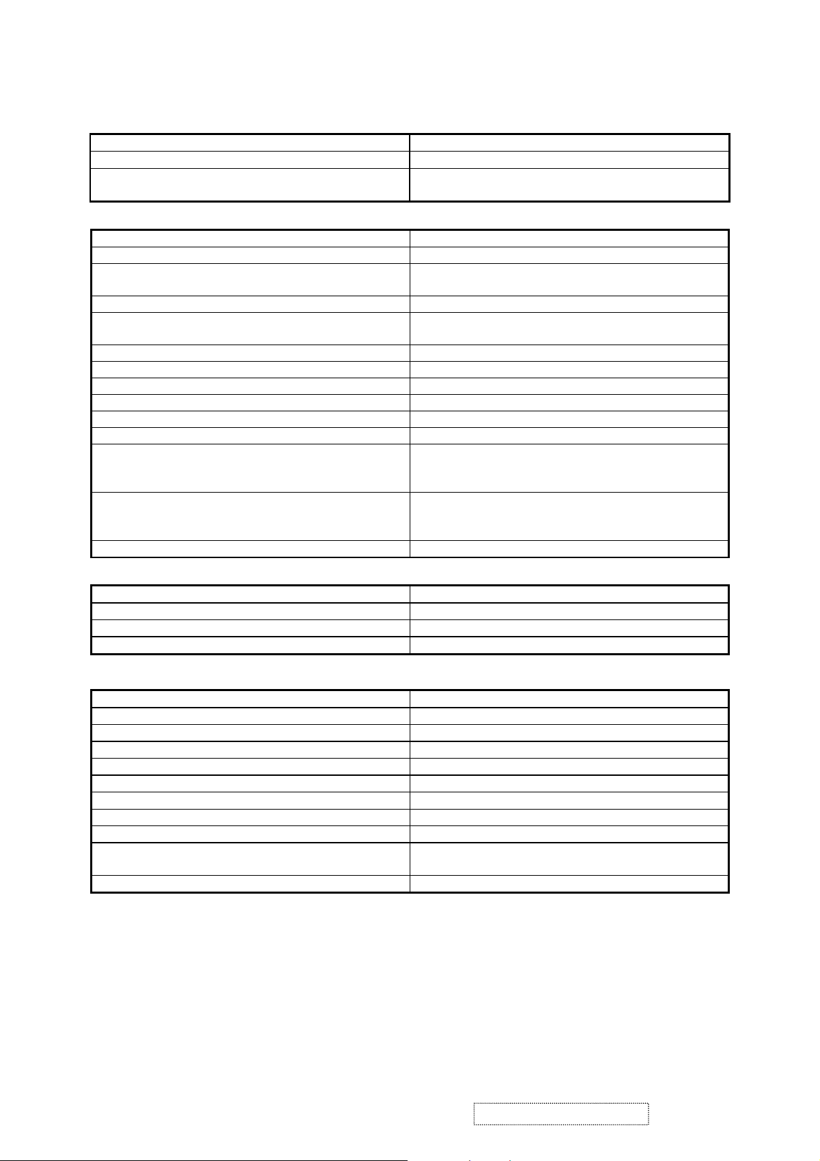
1-5.2 Handling and Placing Methods
Only touch the metal frame of the LCD panel or
the front cover of the monitor.Do not touch the
ssed by fingers
Taking out the monitor by grasping the LCD
Correct Methods: Incorrect Methods:
surface of the polarizer.
Surface of the LCD panel is pre
and that will probably cause “Mura”.
Take out the monitor with cushions
panel.That will probably cause “Mura”.
ViewSonic Corporation Confidential
-
3
Do Not Copy Q9-1_Q9b-1
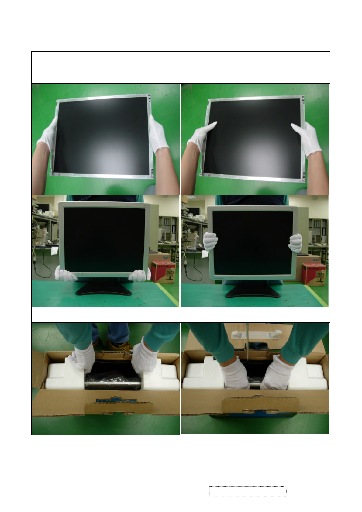
The panel is placed facedown on the lap. That
Place the monitor on a clean and soft foam pad.
Placing the monitor on foreign objects. That will
probably scratch the surface of the panel or
cause “Mura.”
will probably cause “Mura.”
ViewSonic Corporation Confidential
-
4
Do Not Copy Q9-1_Q9b-1
2. SPECIFICATIONS
General Specification
Test Resolution & Frequency 1280x1024 @ 60Hz
Test Image Size Full Size
Contrast and Brightness Controls
Video Interface
Analog Input Connector DB-15 (Analog), refer the appendix A
Default Input Connector Defaults to the first detected input
Video Cable Strain Relief
Video Cable Connector DB-15 Pin out Compliant DDC 1/2B
Video Signals
Video Impedance 75 Ohms (Analog)
Maximum PC Video Signal 950 mV with no damage to monitor
Maximum Mac Video Signal 1250 mV with no damage to monitor
Sync Signals TTL
DDC 1/2B Compliant with Revision 1.3
Sync Compatibility Separate Sync
Video Compatibility
Resolution Compatibility
Exclusions Not compatible with interlaced video
Factory Default:
Contrast = 60%, Brightness = 100%
Equal to twice the weight of the monitor for five
minutes
1. Video RGB (Analog)
Separate,
Shall be compatible with all PC type computers,
Macintosh computers, and after market video
cards
640 x 350, 640 x 480, 720 x 400 (640 x 400), 800
x 600, 832 x 624, 1024 x 768, 1280 x 720, 1280 x
1024,
Horizontal / Vertical Frequency
Horizontal Frequency 30 – 82 kHz
Vertical Refresh Rate 50 – 75 Hz.
Maximum Pixel Clock 140 MHz
Sync Polarity Independent of sync polarity.
POWER SUPPLY
Internal Power Supply Part Number: HOAU172001
Input Voltage Range 90 to 264 VAC
Input Frequency Range 47.5 to 63 Hertz
Over Current Protection 5 A TYPICAL AT 5VDC
Leakage Current 3.5MA (MAX) AT 254VAC / 60HZ
Efficiency 75 % TYPICAL AT 115VAC FULL LOAD
Power Dissipation 45 WATTS (TYP)
Max Input AC Current 1.5 ARMS @ 90VAC, 1 ARMS @180VAC
Inrush Current (Cold Start) 50 A @ 120VAC, 90 A(MAX) @220VAC
Power Consumption
Recovery Time ON Mode = N/A, ACTIVE OFF < 3 sec
ON Mode < 45 W (max) / 35 W (typ)
ACTIVE OFF < 1 W
ViewSonic Corporation Confidential
5
-
Do Not Copy Q9-1_Q9b-1
Timing Table
Item Timing Analog
1 640 x 350 @ 70Hz, 31.5kHz Yes
2 640 x 400 @ 70Hz, 31.5kHz Yes
3 640 x 480 @ 60Hz, 31.5kHz Yes
4 640 x 480 @ 67Hz, 35.0kHz Yes
5 640 x 480 @ 72Hz, 37.9kHz Yes
6 640 x 480 @ 75Hz, 37.5kHz Yes
7 720 x 400 @ 70Hz, 31.5kHz Yes
8 800 x 600 @ 56Hz, 35.1kHz Yes
9 800 x 600 @ 60Hz, 37.9kHz Yes
10 800 x 600 @ 75Hz, 46.9kHz Yes
11 800 x 600 @ 72Hz, 48.1kHz Yes
12 832 x 624 @ 75Hz, 49.7kHz Yes
13 1024 x 768 @ 60Hz, 48.4kHz Yes
14 1024 x 768 @ 70Hz, 56.5kHz Yes
15 1024 x 768 @ 72Hz, 58.1kHz Yes
16 1024 x 768 @ 75Hz, 60.0kHz Yes
17 1280 x 1024 @ 60Hz, 63.4kHz Yes
18 1280 x 1024 @ 75Hz, 79.97kHz Yes
20 1280x 720 @ 60Hz, 45kHz (HDTV) Yes
User Presets
Number of User Presets (recognized timings) Available: 10 presets total in FIFO configuration
Panel Characteristics
Model number “HANNSTAR AND HSD190ME12-A02
Type “TN PANEL TECHNOLOGY”
Active Size 376.32 (H) x 301.056 (V)
Pixel Arrangement RGB Vertical Stripe
Pixel Pitch 0.294 mm
Glass Treatment ANTI GLARE (HARD COATING 3H)
# of Backlights 4 CCFL EDGE-LIGHT (2 TOP / 2 BOTTOM)
Backlight Life 40,000 HOURS (MIN)
Luminance – Condition:
CT = 6500K, Contrast = Max,
Brightness = Max
Brightness Uniformity 75 % Entire Area (minimum)
Contrast Ratio 500:1 (Typ), 350:1 (Min)
Color Depth 16 million colors (x bit panel)
Viewing Angle (Horizontal) 140 deg @ CR>10, 160 deg @ CR>5 (typ)
Viewing Angle (Vertical) 130 deg @ CR>10, 150 deg @ CR>5 (typ)
Response Time
10%-90% @ Ta=25°C
Panel Defects Please see Panel Quality Specifications.
260 cd/m2 (Typ after 30 minute warm up)
200 cd/m2 (Min after 30 minute warm up)
12 ms (Tr =3.6 ms, Tf = 8.4 ms) (Typ)
25ms (Max)
ViewSonic Corporation Confidential
6
-
Do Not Copy Q9-1_Q9b-1
nd
2
Source Panel “CPT and CLAA190EA03
Type “Panel Technology”
Active Size 376.32 (H) x 301.056 (V)
Pixel Arrangement RGB Vertical Stripe
Pixel Pitch 0.294 mm
GLASS TREATMENT Anti Glare (Hard coating 3H)
# OF BACKLIGHTS 4 CCFL edge-light (2 top / 2 bottom)
BACKLIGHT LIFE 40,000 Hours (Min) / 50,000 Hours (typ)
Luminance –
Condition:
250 cd/m2 (Typ after 30 minute warm up)
200 cd/m2 (Min after 30 minute warm up)
CT = 6500K, Contrast = Max, Brightness
= Max
Brightness Uniformity 75 % Entire Area (minimum)
Contrast Ratio 500:1 (Typ), 400:1 ( Min)
Color Depth 16 million colors (x bit panel)
Viewing Angle (Horizontal) 150 deg @ CR>10, 170 deg @ CR>5 (typ)
VIEWING ANGLE (VERTICAL) 130 deg @ CR>10, 170 deg @ CR>5 (typ)
Response Time
10%-90% @ Ta=25°C
12 ms (Tr= 5 ms, Tf = 7 ms) ( Typ)
25 ms (Tr= 10 ms, Tf = 15 ms) (Max)
Panel Defects Please see Panel Quality Specifications.
IMAGE PERFORMANCE
Factory Defaults
Item Defaults Item Defaults
Contrast 60% 720x400/640x400 720x400
Brightness 100% Resolution Notice Enabled
Color Temperature 6500K Volume N/A
Sharpness 50% Balance N/A
OSD H. Position 50% Treble N/A
OSD V. Position 50% Bass N/A
OSD Time Out 20 Sec
OSD Blending 100%
Dimension
Width 430 mm
Height 435 mm
Depth 194 mm
Monitor Weight 4.4 kg / 9.68 lbs
Ergonomics
Tilt Up +19° +/- 1° DEGREES MINIMUM
Tilt Down -1 °+/- 1° degrees
ViewSonic Corporation Confidential
7
-
Do Not Copy Q9-1_Q9b-1
u
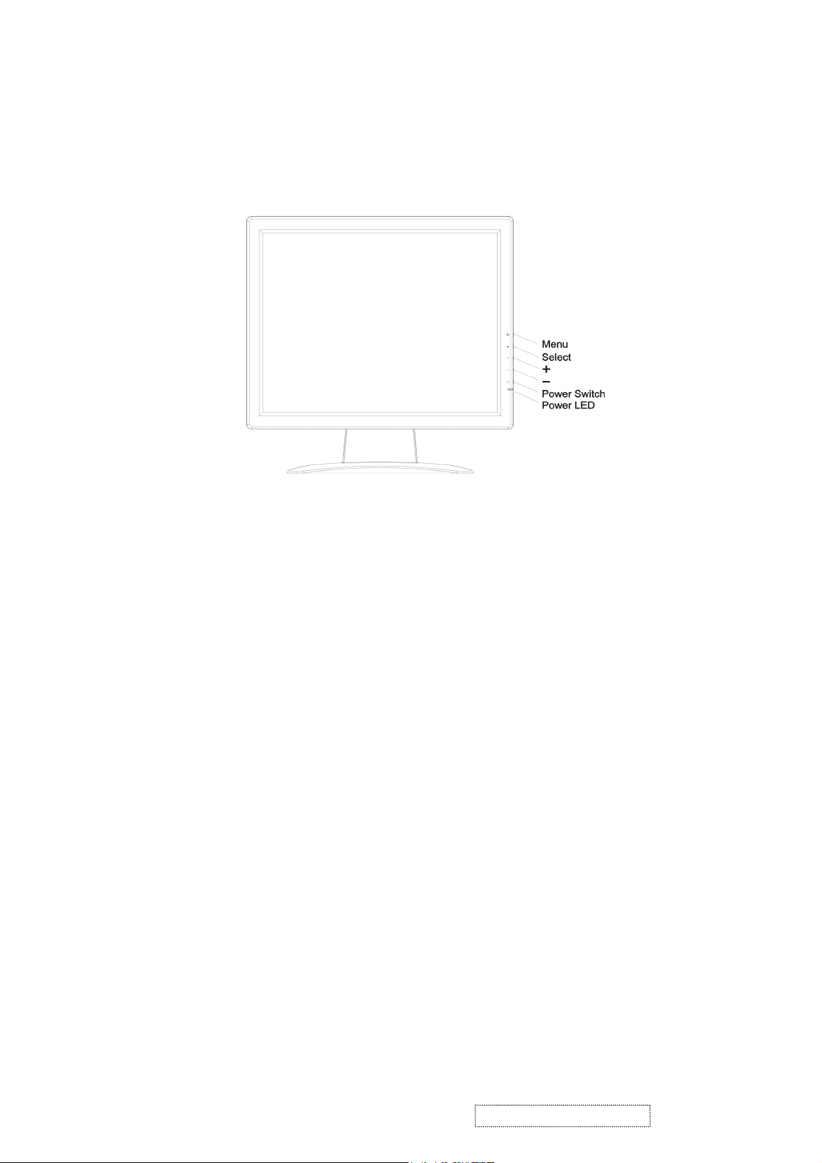
3. Front Panel Function Control Description
3-1 Location of Controls
Display Controls
1) MENU:
Enter to the OSD adjustment menu. It also used for go back to previous menu for sub-men
and the change data don’t save to memory.
2) SELECT:
To confirm the current selection. It also used for go back to previous menu for sub-menu,
and the change data will be saving to memory.
If pressed when menu is not active, VOLUME is adjusted.
3) ADJUST +: (RIGHT)
To scroll up in sub menu or to increase value of selected item.
If pressed when menu is not active, BRIGHTNESS is adjusted.
4) ADJUST —: (LEFT)
To scroll down in sub menu or to decrease value of selected item
If pressed when menu is not active, AUTO CINFIG is adjusted.
5) POWER SWITCH:
Pushing the power switch will turn the monitor on. Pushing it again to turn the monitor
off.
6) POWER INDICATOR:
The LED will light with green color in normal on state, and will light with flash in power
saving mode.
ViewSonic Corporation Confidential
8
-
Do Not Copy Q9-1_Q9b-1
b
u
f
s
m
3-2 OSD Menu Controls
Screen Adjustment Operation Procedure
1) Entering the screen adjustment
The setting switches are normally at standmain menu of the screen adjustment. The adjustable items will be displayed in the main
menu.
2) Entering the settings
Use the Adjust - and Adjust + buttons to select the desired setting icon and push
the SELECT button to enter sub-menu.
3) Change the settings
After the sub-menu appears, use the Adjust - and Adjust + buttons to change the
setting values.
4) Save
After finishing the adjustment, push the SELECT button to memorize the setting.
5) Return & Exit the main menu
To go back to the previous menu, push the MEMU button.
y. Push the MENU button once to display the
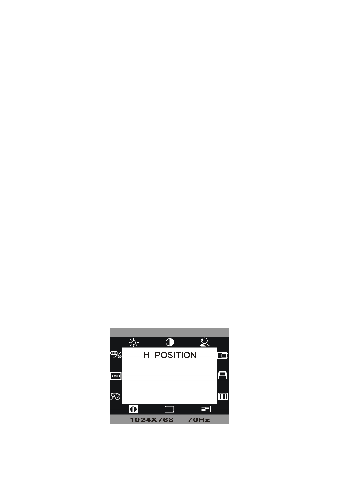
The Screen Adjustment
Main Menu
The OSD main menu (Figure 8-1) is displayed on screen when MENU key is pressed. The OSD men
is a combination of graphic and text display. The column inside the OSD menu will show information o
input image. Second column beneath OSD menu shows the item selected.
The LEFT and RIGHT keys are used to scroll through items within the menu. The selected item i
highlighted as the scrolling moves along. The SELECT key is used to activate the highlighted ite
during this state.
Figure 8-1
ViewSonic Corporation Confidential
9
-
Do Not Copy Q9-1_Q9b-1
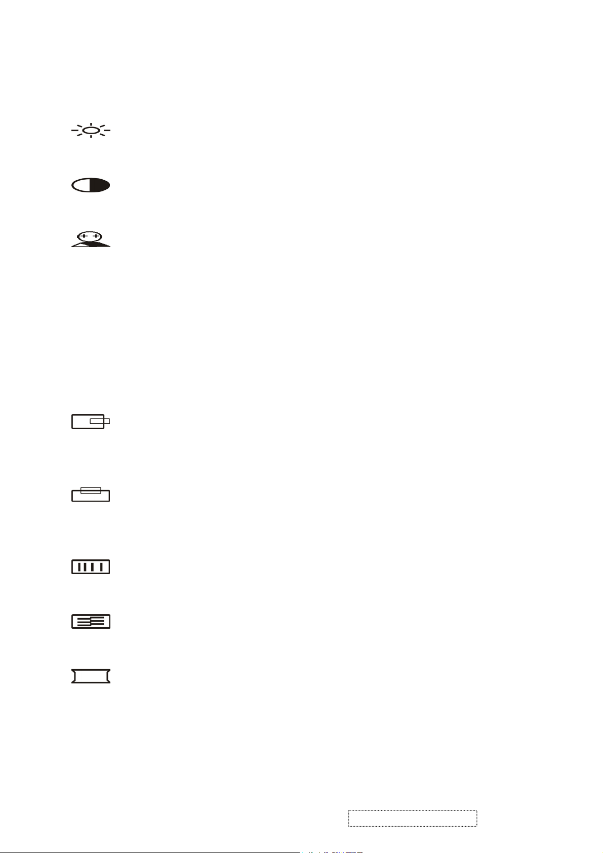
OSD adjusting and Controls
d
s
s
h
h
BRIGHTNESS
Setup the brightness of the panel.
CONTRAST
The Contrast menu item is used to adjust image contrast.
AUTO CONFIG
There are two items: AUTO ADJUST and AUTO COLOR. Use the Adjust [+] an
[-] key to scroll up and down in menu, and then press the SELECT key to start thi
function. If the MENU key is pressed, the main menu is re-displayed and nothing i
changed.
AUTO ADJUST: Used to perform automatic configuration of the phase、clock、
vertical and horizontal positioning.
AUTO COLOR: It is used to adjust the gain and offset of the Red, Green and Blue
channels on the ADC automatically.
H-POSITION
H-Position is used to adjust the horizontal image position manually. A slider wit
current value is displayed.
V-POSITION
V-Position is used to adjust the vertical image position manually. A slider wit
current value is displayed.
CLOCK
Reduce vertical stripes in the screen image.
PHASE
Reduce horizontal stripes in the screen image.
SHARPNESS
This can adjust the video quality to be sharp or blur (special for text mode).
ViewSonic Corporation Confidential
10
-
Do Not Copy Q9-1_Q9b-1
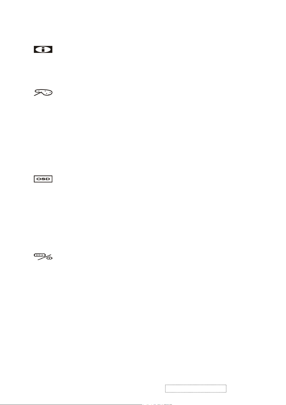
INFORMATION
e
l
D
The “INFORMATION” menu provides the user with detailed information regarding th
current input format and version (include resolution, vertical /horizontal frequency, pixe
clock and software version).
COLOR
Configure the image color. There are three items : 9300K、6500K、USER MODE.
9300K: The item “9300K” is used to default 9300K color temperature.
6500K: The item “6500K” is used to default 6500K color temperature.
USER MODE:
RGB ADJUST:
-RED: The item “RED” is used to adjust the gain of red channel in ADC.
-GREEN: The item “GREEN” is used to adjust the gain of green channel in ADC.
-BLUE: The item “BLUE” is used to adjust the gain of blue channel in ADC.
OSD MENU
There are five items: OSD H POSITION, OSD V POSITION, OSD BLENDING, OS
TIME OUT and LANGUAGE.
OSD H POSITION: The item “OSD H Position” is used to setup the OSD menu H position.
OSD V POSITION: The item “OSD V Position” is used to setup the OSD menu H position.
OSD BLENDING: To adjust the blending of the OSD MENU.
OSD TIME OUT: “OSD Time out” is used to set the timeout of the OSD menu.
There are three options for the automatic timeout: 20, 40 and 60 seconds.
MISC MENU
There is one item: reset.
RESET: Press “Reset” to return the monitor to its factory default settings.
ViewSonic Corporation Confidential
11
-
Do Not Copy Q9-1_Q9b-1

How to use AUTO CONFIG Adjustment
This function can tune the parameters of PHASE、CLOCK、H-POSITION and
V-POSITION.
Suggesting Adjustment Steps:
Step 1: Enter the “Windows” Shut-down frame. ( Note:The Wallpaper color CAN NOT be
black.)
Step 2: Enter OSD Main Menu and choose the “AUTO CONFIG” item, then press SELECT
key. The Picture will auto-adjust by itself. After 4 seconds, you can exit OSD and
Shut-down frame.
Step 3: If you are not still satisfied with the picture quality, you could choose CONTRAST
item in OSD Main Menu and adjust it.
Note:
1. If you don’t like the effect of AUTO CONFIG adjustment, you can adjust PHASE,
CLOCK… items in OSD.
2. AUTO CONFIG adjustment can be used in “Windows” except black background frame, but
the best effect is in the SHUT DOWN frame.
3. It is recommend running “EDIT” program first, then doing AUTO CONFIG adjustment in
DOS mode.
ViewSonic Corporation Confidential
12
-
Do Not Copy Q9-1_Q9b-1
3-3 Hot Key for Function Controls
Buttons: Functions:
[Manual] Main menu
[Enter] Select / Exit
[+] To immediately activate Brightness menu.
[-]
[+] + [PW] + Main Power On All Reload
No signal + [Enter] + Main
Power on
Signal + [PW] +[ Enter] + Main
Power on
Remark : All the short cuts function are only available while OSD off
Auto config
Burning mode
Factory Mode
ViewSonic Corporation Confidential
13
-
Do Not Copy Q9-1_Q9b-1
4. Circuit Description
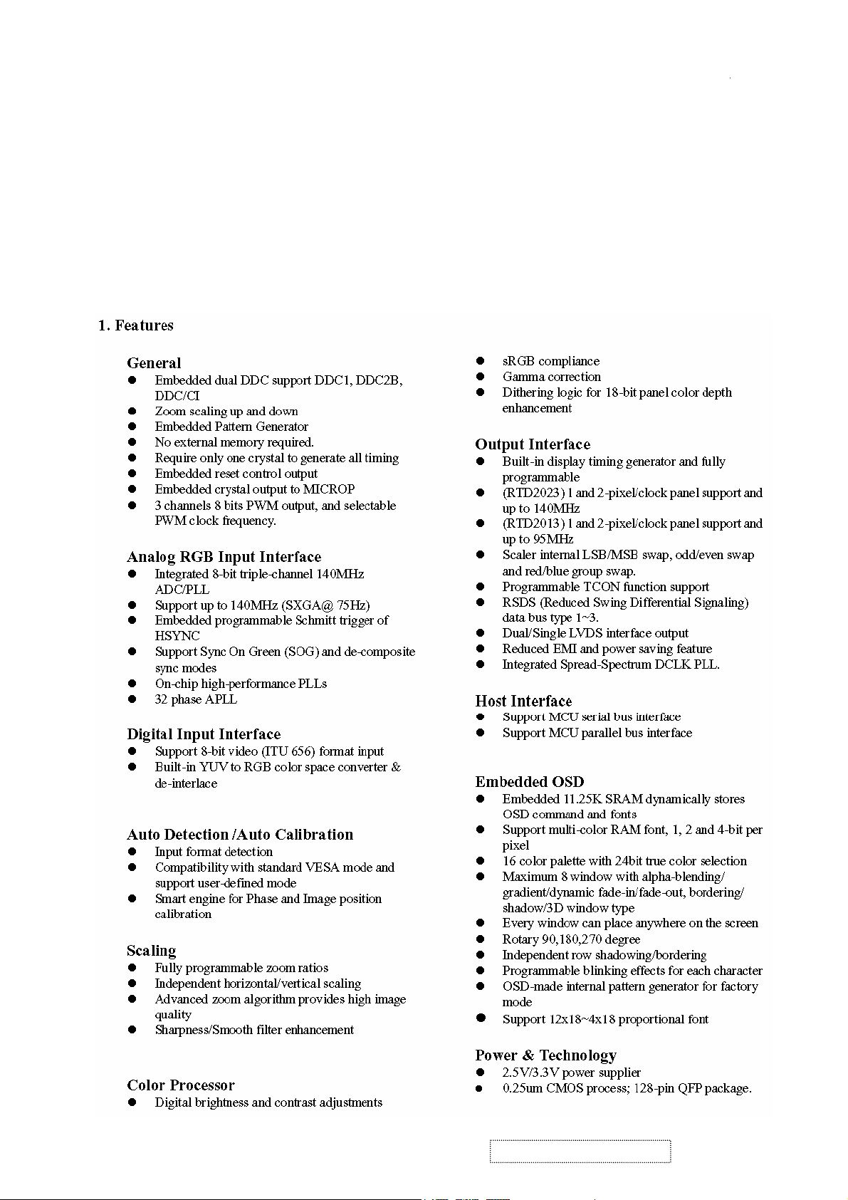
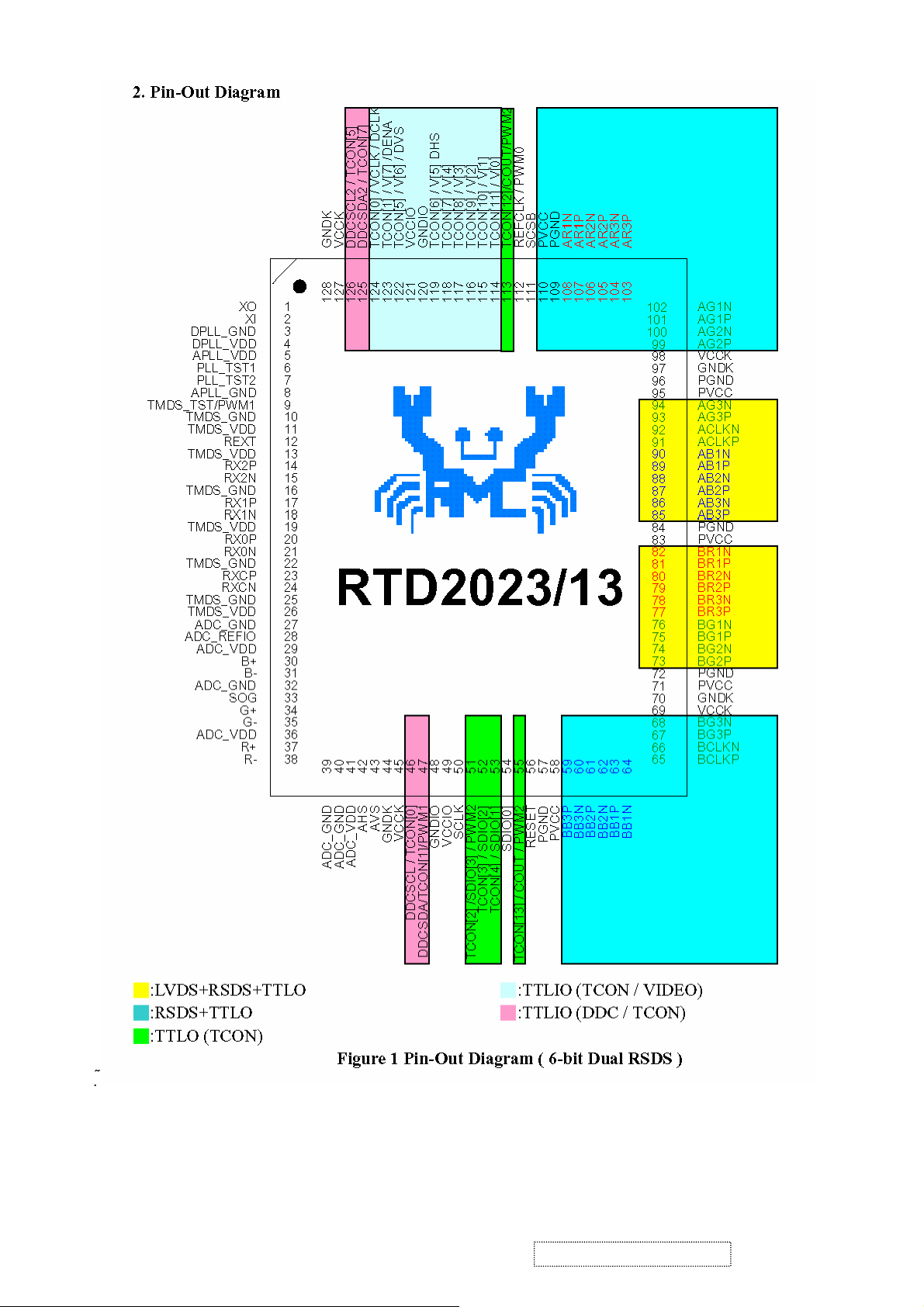
1. WORKING THEOREM
A. Scaler
The RTD2023 is total solution graphics processing IC for LCD monitors with panel resolutions up to SXGA. It is configured with integrated 8bit triple-ADC/PLL, a high quality display processing engine, and an integrated output display interface that can support Dual / Single LVDS
panel interface format. To further reduce system costs, the RTD2023 also integrates intelligent power management control capability for
green-mode requirements and spread-spectrum support for EMI management. The RTD2023 incorporates the world’s first coherent
oversampled RGB graphics ADC in a monitor controller system1. The oversampling ADC samples the input RGB signals at a frequency that
is much higher than the signal source pixel rate. This can preserve details in the video signal that ordinarily would be lost due to input signal
jitter or bandwidth limitations in non-oversampled systems.
B. MCU:
The MTV512M micro-controller is an 8051 CPU core embedded device especially tailored for flat panel display application. It
includes an 8051 CPU core, a 768K-byte SRAM, 4 channels of 6-bit ADC,3 external counters / timers ,6 channels of PWM
DAC,VESA DDC interface, and a 64k-byte internal program Flash-ROM memory. of 6-bit ADC, and a built-in , It also includes two
IIC Slave B ports, supporting VESA DDC/CI for D-sub interfaces, and a Boot-Code-Free ISP (In System Programming).
ViewSonic Corporation Confidential
14
-
Do Not Copy Q9-1_Q9b-1
ViewSonic Corporation Confidential
15
-
Do Not Copy Q9-1_Q9b-1
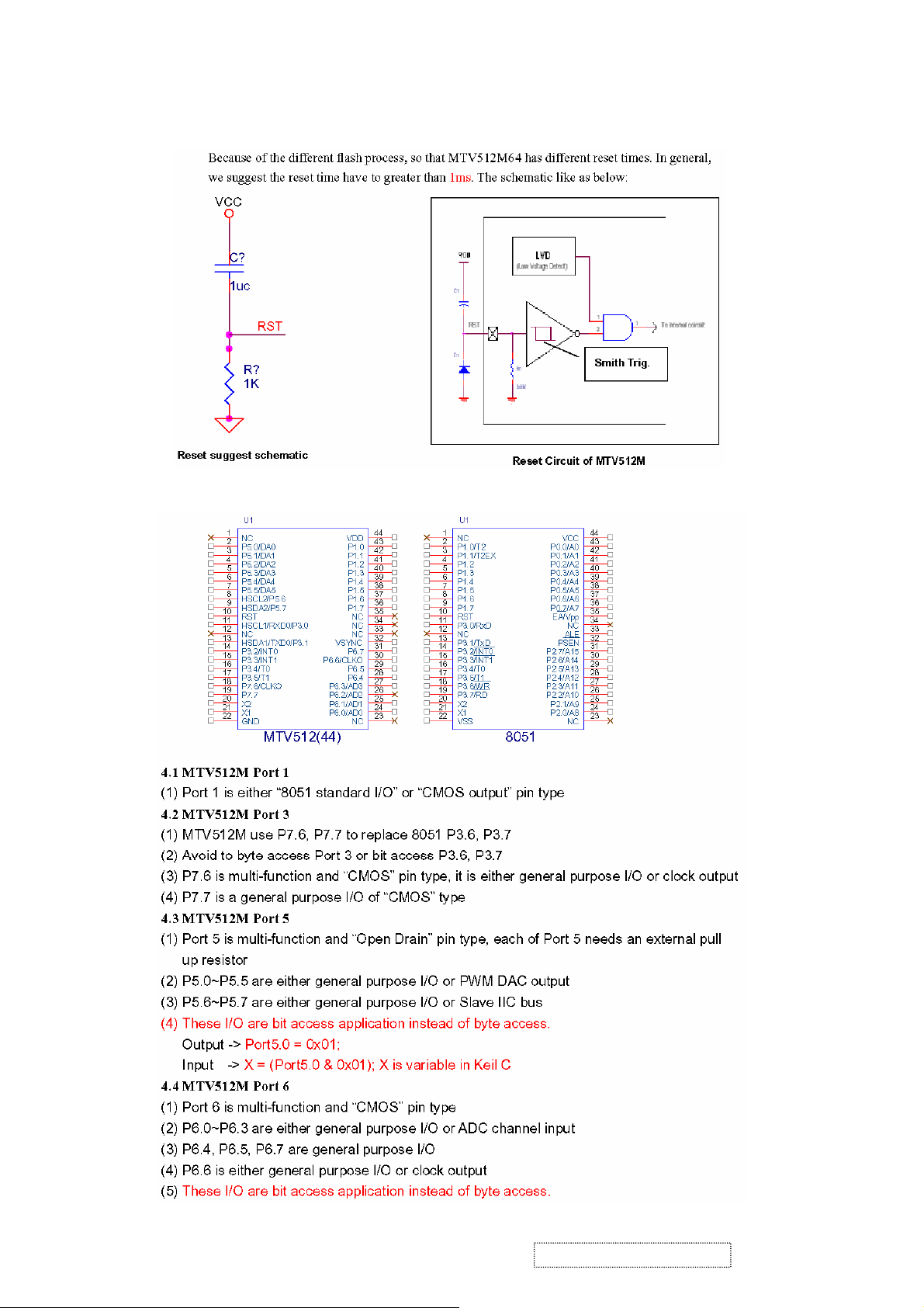
B. MCU:
Hardware Design Attention :
(1). Reset Time :
(2). Pin assignment of MTV512M and 8051
ViewSonic Corporation Confidential
16
-
Do Not Copy Q9-1_Q9b-1
(3). Special application
ViewSonic Corporation Confidential
17
-
Do Not Copy Q9-1_Q9b-1
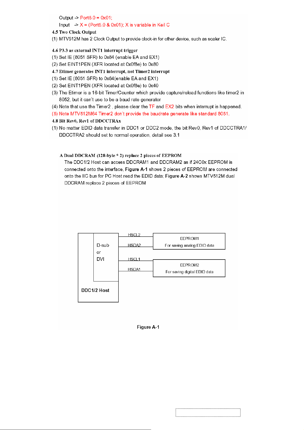
 Loading...