

Page 1

ViewSonic Pro8400
Model No. VS13647
DLP Projector
(Pro8400 SM Rev. 1a Feb. 2011)
ViewSonic 381 Brea Canyon Road, Walnut, California 91789 USA - (800) 888-8583
Service Manual
Page 2
Copyright
Copyright© 2010 by ViewSonic Corporation. All rights reserved. No part of this publication may be
reproduced, transmitted, transcribed, stored in a retrieval system, or translated into any language or
computer language, in any form or by any means, electronic, mechanical, magnetic, optical, chemical,
manual or otherwise, without the prior written permission of ViewSonic Corporation.
Disclaimer
ViewSonic makes no representations or warranties, either expressed or implied, with respect to the contents
hereof and specifically disclaims any warranty of merchantability or fitness for any particular purpose. Further,
ViewSonic reserves the right to revise this publication and to make changes from time to time in the contents
hereof without obligation of ViewSonic to notify any person of such revision or changes.
Trademarks
Optiquest is a registered trademark of ViewSonic Corporation.
ViewSonic is a registered trademark of ViewSonic Corporation.
All other trademarks used within this document are the property of their respective owners.
Revision History
Revision SM Editing Date ECR Number Description of Changes Editor
1a GG02/22/11 Sophia Kao
Confidential - Do Not Copy
ViewSonic Corporation
All content on this SM had approved by PE, Charles
Pro8400
i
Page 3

Table of Contents
1 System Introduction ................................................................ ................................ .............. 1
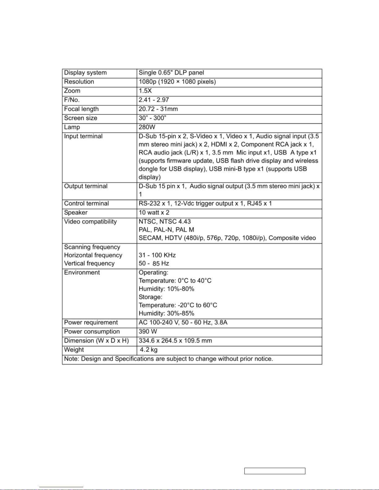
1.1 Technical Specification ..................................................................................................1
1.2 Location of Features, Controls, and I/O ........................................................................ 2
1.3 Pro8400 Lamp Specification ..........................................................................................9
1.4 Pro8400 System Block Diagram .................................................................................12
2 Firmware (PixelWorks) Upgraded Flow ................................................................ .............. 13
2.1 Setup Tool/Equipment ..................................................................................................13
2.2 Upgrading Procedure ...................................................................................................13
3 Machine Disassembly and Replacement ................................ ................................ ............ 14
3.1 Tools ...............................................................................................................................14
3.2 Disassembly Procedure ...............................................................................................15
3.3 Assembly FAN Module.................................................................................................23
3.4 Disassembly Lamp Module ..........................................................................................24
4 Troubleshooting and Verifying the Repair ................................ ................................ ........... 25
4.1 Troubleshooting ............................................................................................................25
4.2 Verifying the Repair ......................................................................................................32
5 Adjustment / Alignment Procedure ................................ ................................ ...................... 38
5.1 Color Wheel Index Adjustment ....................................................................................38
5.2 ADC Calibration ............................................................................................................39
5.3 Keystone Adjustment ....................................................................................................41
6 Connector Information ................................ ................................ ................................ ........ 42
6.1 Main Board ................................ ....................................................................................42
6.2 The backside of Main Board ........................................................................................42
6.3 Ballast Board .................................................................................................................43
6.4 Power Board..................................................................................................................44
7 FRU (Field Replaceable Unit) List ................................ ................................ ...................... 45
7.1 Mechanical Drawing .....................................................................................................46
7.2 Packing drawing ............................................................................................................48
8 Maintenance ................................................................ ................................ ....................... 51
Appendix A: RS-232 Command and Configuration ................................................................ .... 52
Appendix B: IR Control Code ................................................................................................ .....54
Appendix C: How to reset the Lamp Hours ................................................................ ................ 55
Confidential - Do Not Copy
ViewSonic Corporation
Pro8400
ii
9 Recommended Spare Parts List ................................................................. ........................ 56
Page 4
1 System Introduction
1.1 Technical Specification
Confidential - Do Not Copy
ViewSonic Corporation
Pro8400
1
Page 5
1.2 Location of Features, Controls, and I/O
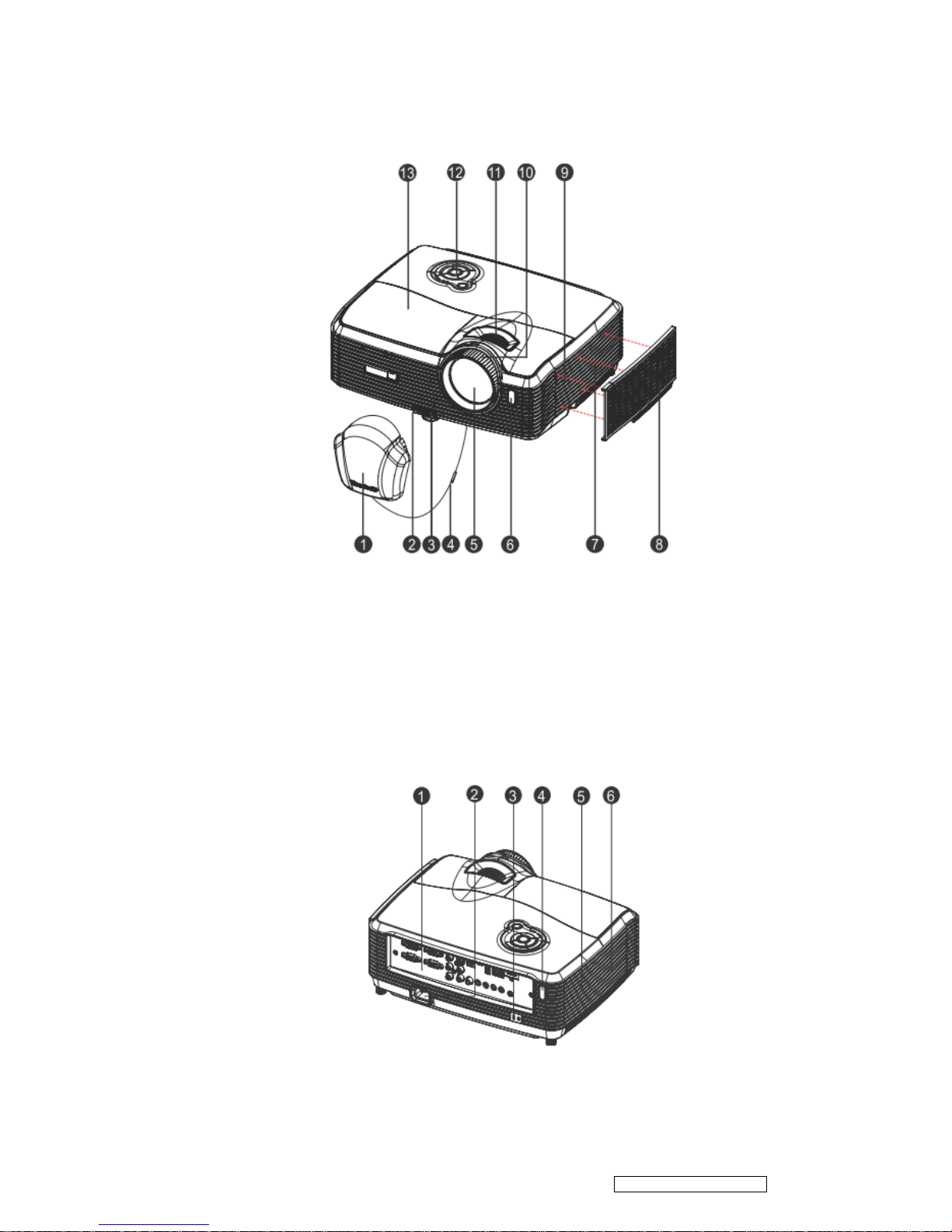
A. Projector overview
Front View
1. Lens cap 8. Filter cover
2. Elevator button 9. Speaker
3.Elevator foot 10.Focus ring
4. Lens cap strap 11.Zoom ring
5. Projection lens 12.Control panel
6. Front IR remote control sensor 13.Lamp cover
7. Ventilation holes (intake)
Real View
Confidential - Do Not Copy
ViewSonic Corporation
Pro8400
2
Page 6
1. Connection ports 2. AC power socket
3. Kensington lock 4. Rear IR remote control sensor
5. Speaker 6. Ventilation holes (exhaust)
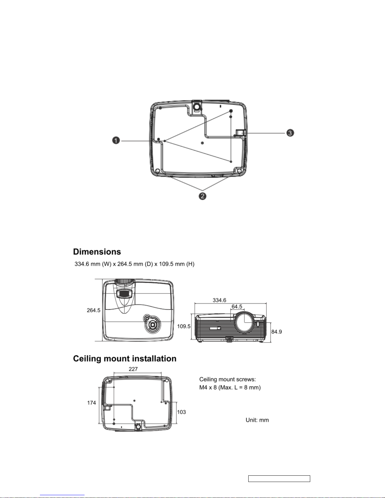
Bottom View
1. Ceiling mount (M4*8)
2. Tilt-adjustment feet
3. Security bar
Confidential - Do Not Copy
ViewSonic Corporation
Pro8400
3
Page 7
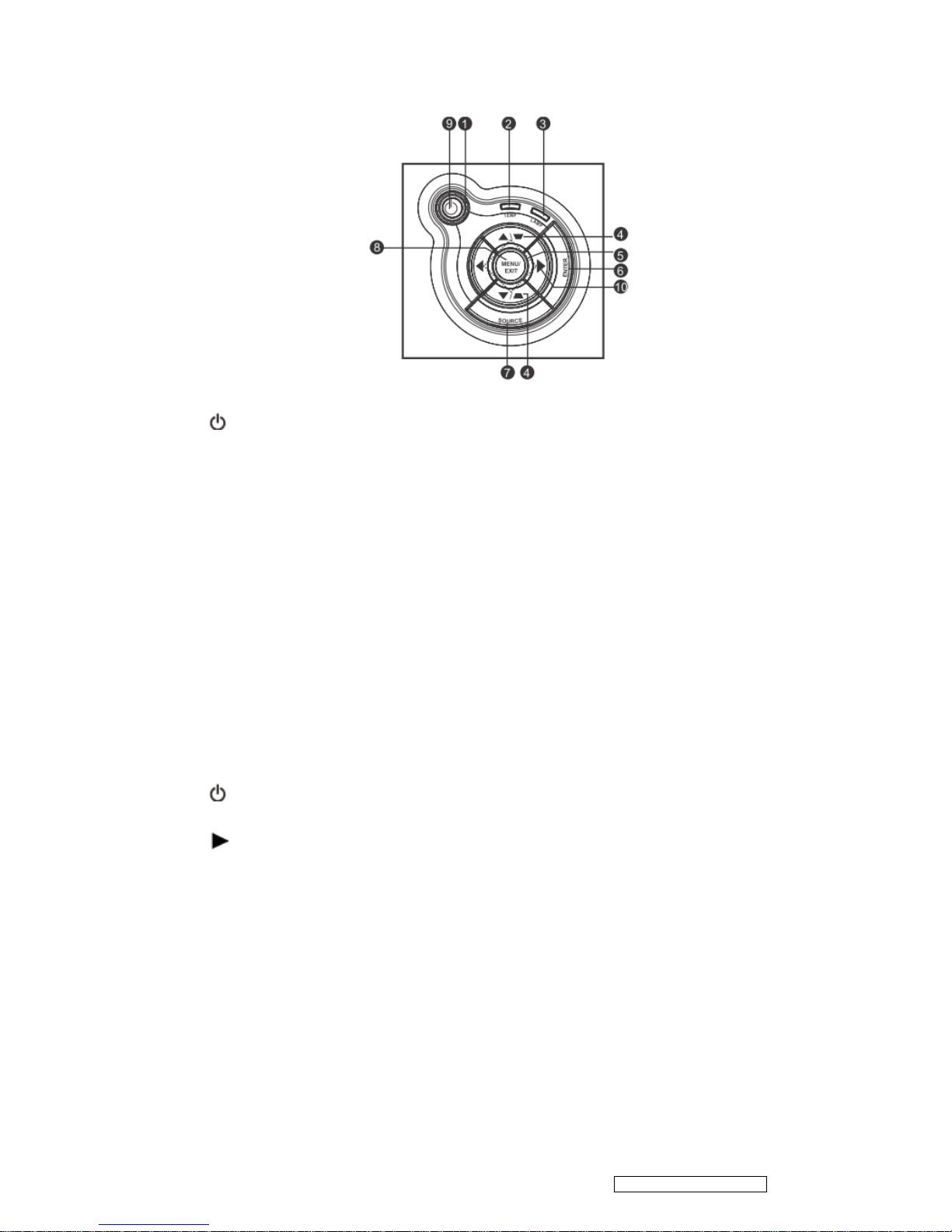
B. Button function and LED indicator
LED
1. Power (Power LED indicator)
2. TEMP (Temperature LED indicator)
3. LAMP (Lamp LED indicator)
Button function
4. Keystone/Arrow keys /Up, /Down)
Manually correct distorted images resulting from an angled projection.
5. Four directional buttons
Use four directional buttons to select items or make adjustments to your selection.
6. ENTER
Enter to sub-menu and confirm the menu selecti on.
7. SOURCE
Display the source selection bar .
8. MENU/EXIT
Display or exit the on -screen display menus.
9. Power
Turn the projector on or off.
10. Right/Panel key
Activate panel key lock.
Confidential - Do Not Copy
ViewSonic Corporation
Pro8400
4
Page 8

C. Connection ports
1. RS232
When operating th e projector via a computer, connect this to the controlling computer's
RS-232C port.
2. Monitor Out
Connect to a computer display, etc.
3. Component (Y Cb/Pb Cr/Pr)
Connect Y Cb/Pb Cr/Pr output from video equipment to this jack.
4. S-Video
Connect S-Video output from video equipment to this jack.
5. USB B
USB display supports computer connection via USB mini -B type to A type cable.
6. USB A
This connector supports firmware update , USB flash drive display and wireless dongle for USB
display.
7. LAN
For LAN display/ network control and web server .
8. HDMI 1
Connect HDMI output from video equipment to this jack.
9. HDMI 2
Connect HDMI output from video equipment to this jack .
Confidential - Do Not Copy
ViewSonic Corporation
Pro8400
5
Page 9

10. DC 12V Out
12V DC out
11. MIC in
Microphone input jack.
12. Audio Out
Connect to a speaker or other audio input equipment.
13. Audio 2
Connect an audio output from video equipment or computer to this jack.
14. Audio 1
Connect an audio output from video equipment or computer to this jack.
15. Audio 3 (L/R)
Connect an audio o utput from video equipment to this jack.
16. Video
Connect composite video output from video equipment to this jack.
17. Computer in 2
Connect image input signal (analog RGB or component) to this jack.
18. Computer in 1
Connect image input signal (analog RGB or component) to this jack.
Confidential - Do Not Copy
ViewSonic Corporation
Pro8400
6
Page 10
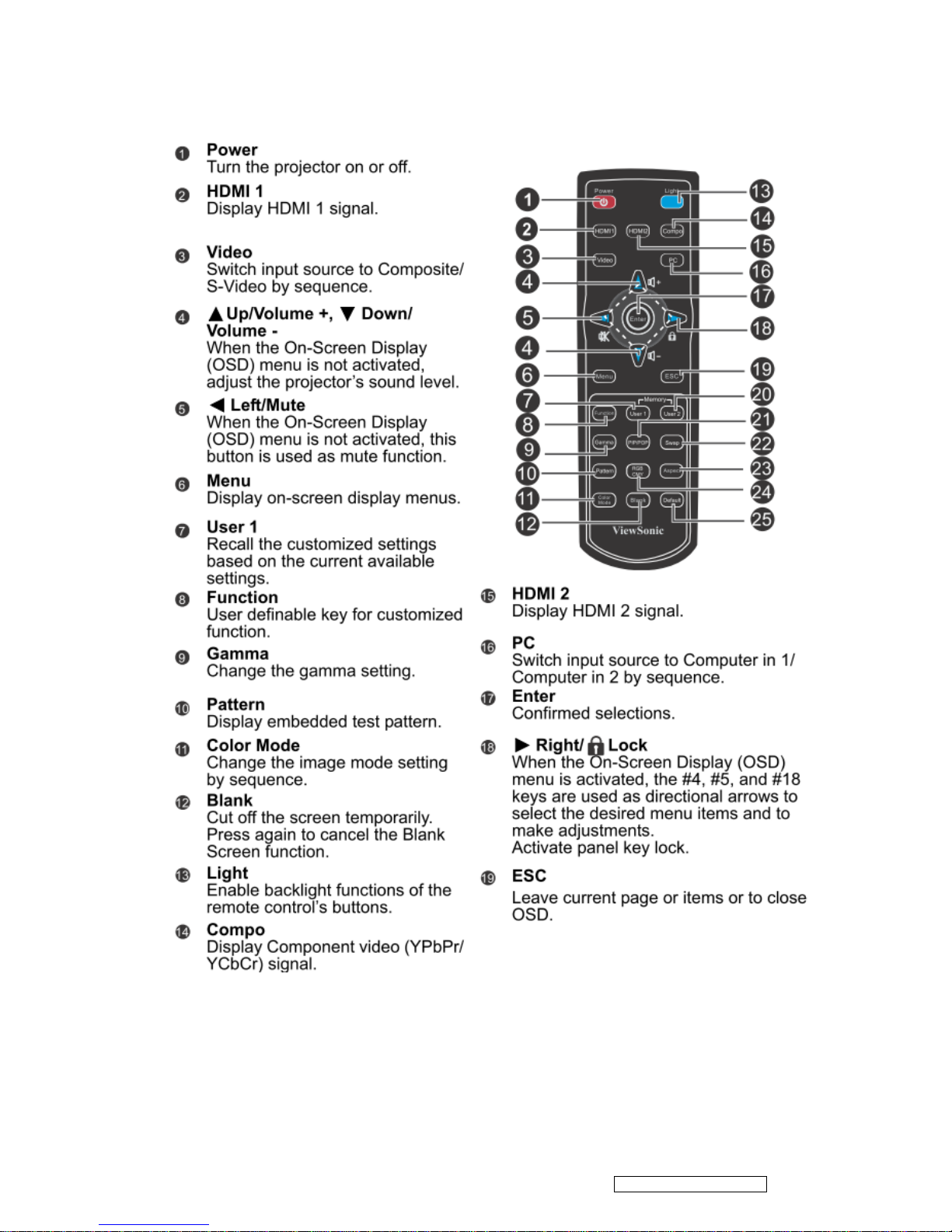
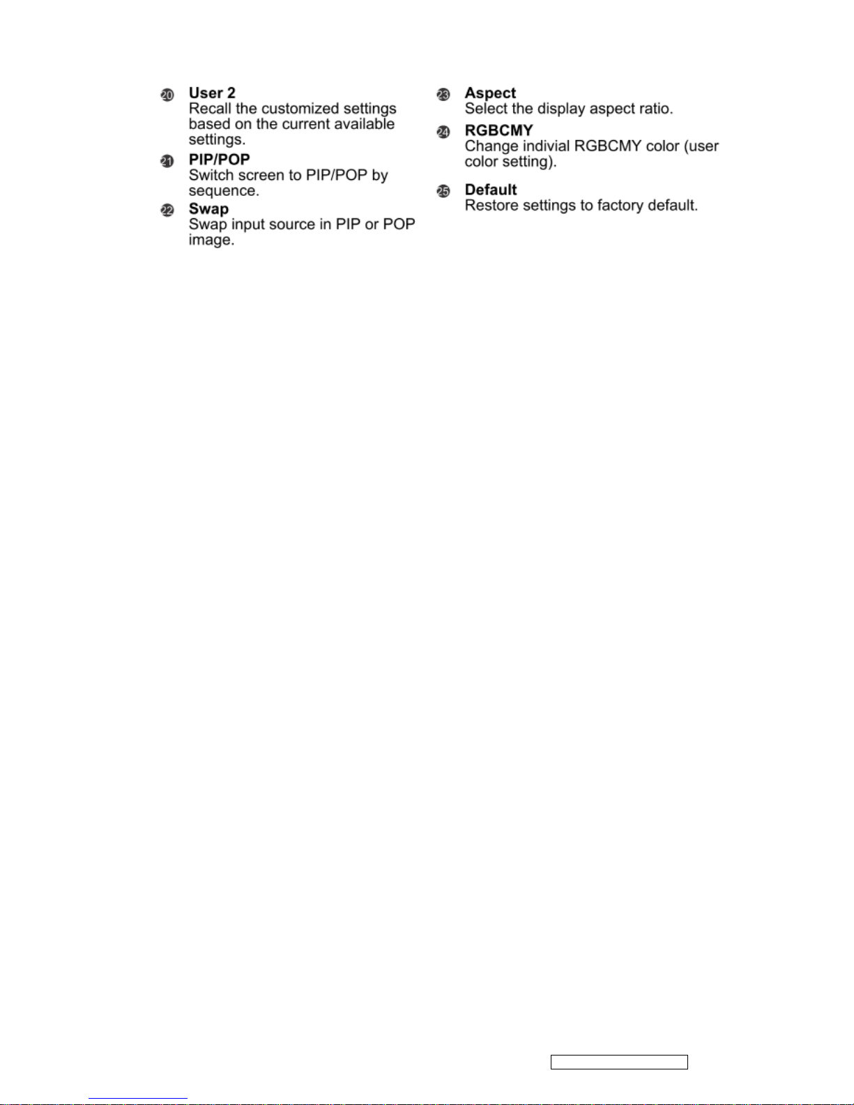
D. Remote Control
Confidential - Do Not Copy
ViewSonic Corporation
Pro8400
7
Page 11
Confidential - Do Not Copy
ViewSonic Corporation
Pro8400
8
Page 12

1.3 Pro8400 Lamp Specification
Product Scope
The product is a lamp system consisting of a short arc burner within a reflector and electronic lamp
driver.
Type lamp P-VIP 280/0.9 E20.8e
Identcode : A 737 57A (FC, non-grinding)
Type driver PT VIP O3 TOP 280W unipro AS
Identcode : A 741 73B (lock type,Gen5,VC, unipro)
The lamp must be operated with the OSRAM lamp driver only.
Initial Characteristics
nominal tolerance
Input Voltage 380V DC 250…400V DC
Standby(non-operating) min. 120V DC
Max. slew rate of input voltage
During switch on 30Vμs
Input Current 0.8A
Max. input voltage ripple 30Vpp@ 100/120Hz
Max. input current ripple 1Arms@40 -300kHz
Input Wattage max.308W @280W lamp wattage
Input Wattage standby operation 1,7W typical 2.5W max.
Output Wattage
nominal 280W 3%
4
DIM mode 230W 3%
4
controlled by UART 230W…280W in step with of 1/128 of nominal power
Output current limitation 4.6A(RMS) 5%
Ignition pulse typ.2.5kVpeak symm. 2.1…3.5 kVpeak
Ignition Phase Duration typ.3.5s max.6 s
Enable-Disable-Enable Cycle 15 s minimum
Acoustic sound pressure level typical acoustic sound pressure level tbd dB(A) at 25cm
measuring distance; measured in steady state lamp
operation
5
Acoustic sound power level typical acoustic sound power level tbd dB(A) acc. to EN
ISO 3744; measured in steady state lamp operation
5
Switch-off lamp voltage 140V 5V
Cooling method forced air cooling at1.5 m/s minimum
Thermal Protection Tc1 switch point 955
Confidential - Do Not Copy
ViewSonic Corporation
Pro8400
9
Page 13

Safety Protections The lamp connections are not mains isolated, The lamp
can be switched on via the Start Control Input signal(SCI).
A Flag Output signal indicates if the lamp has lit rightly. The
Start Control Input and the Flag Output are mains isolated.
Note:
4
Measured at real lamp load. Deviations will occur on all kind of artificial loads (e.g.
resistor)
5
Measured with RGB waveform. Customer generated UNISHAPE waveforms can lead to
noise deviation.
Attention for handling
Do not touch the lamp until it has cooled completely, because the lamp is very hot
during operation and immediately after turned off.
The lamp has to be fixed firmly to the base or socket.
Turn off the power supply during maintenance.
Do not hold the lamp except outer surface of the reflector.
Wear protective gloves and eyeglasses when handling the lamp.
Any unusual shock or vibration to the lamp should be avoided.
The lamp contains the mercury. Its breakage might cause mercury to flow out of the
reflector. Please manage provision at the customer’s product.
Do not pull the lead wire and plug by more than 24.5N.
Please be careful of handling the lamp because it is made of glass.
Please notice for keeping or handling the lamp, because there is a projection of this
lamp with reflector ahead.
Do not touch the bulb and the mirror area of the reflector.
Attention for use
Do not close or cover the lamp with any flammable stuff.
During operation, the lamp is under extremely high pressure. Please manage
provision at the customer ’s product to prevent fragments of bulb and mercury from
flowing out of it. If the lamp bursts in case of an emergency, the sound will be
occurred.
Lamp operation should be with the specified lamp driver and the system ONLY.
Do not look at the lamp directly during operations.
Do not expose your skin directly. We recommend to you to put on something for
protection for your skin. For example, long sleeve shirt, gloves, glassed and so on.
Do not modify the lamp and never use a lamp tha t has been modified.
Any unusual shock or vibration to the lamp should be avoided during operation.
Do not use any broken lamps.
Confidential - Do Not Copy
ViewSonic Corporation
Pro8400
10
Page 14

Dispose of used lamps according to your local instruction.
Do not turn on the lamp while the system is opened.
The lamp contains mercury. If the lamp bursts during operation ventilate the area
sufficiently to avoid inhaling harmful mercury fumes.
Use the lead below 200
C to prevent a deterioration of cladding clad of the
fluorocarbon resin.
The lead wire insulation clad shouldn ’t touch the reflector.
Exchange the lamp that has already passed the life time immediately.
Confidential - Do Not Copy
ViewSonic Corporation
Pro8400
11
Page 15
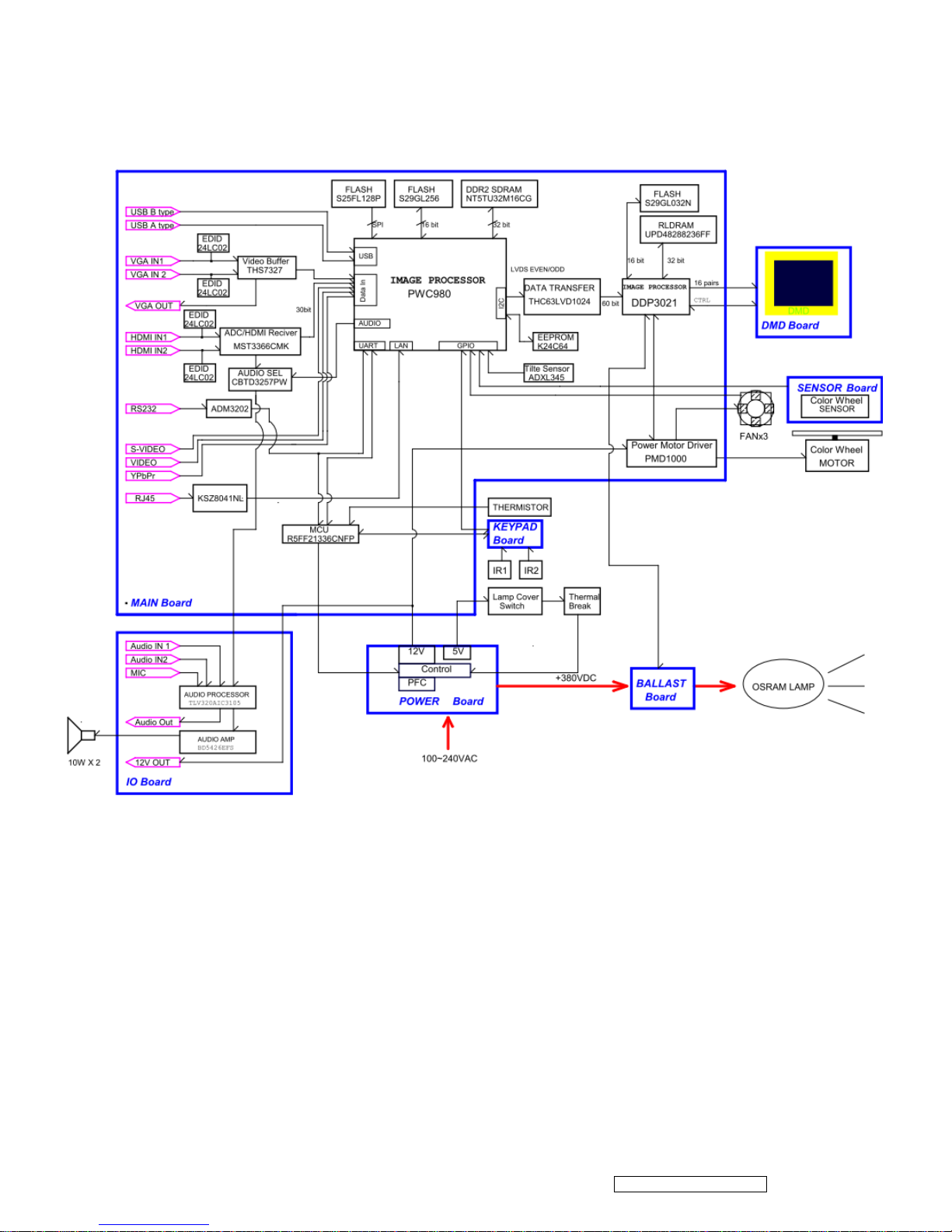
1.4 Pro8400 System Block Diagram
Confidential - Do Not Copy
ViewSonic Corporation
Pro8400
12
Page 16
2 Firmware (PixelWorks) Upgraded Flow
This chapter provides the information regarding relevant equipments and upgrading
procedure for f irmware upgrade.
Note:
Please check the firmware and composer version before any f irmware upgrade procedures.
During firmware download period, please do not shut down PC or projector , this will cause flash
memory’s damage. And need to return the unit t o manufacturer for flash memory recovery.
2.1 Setup Tool/Equipment
USB Disk
Power Cord
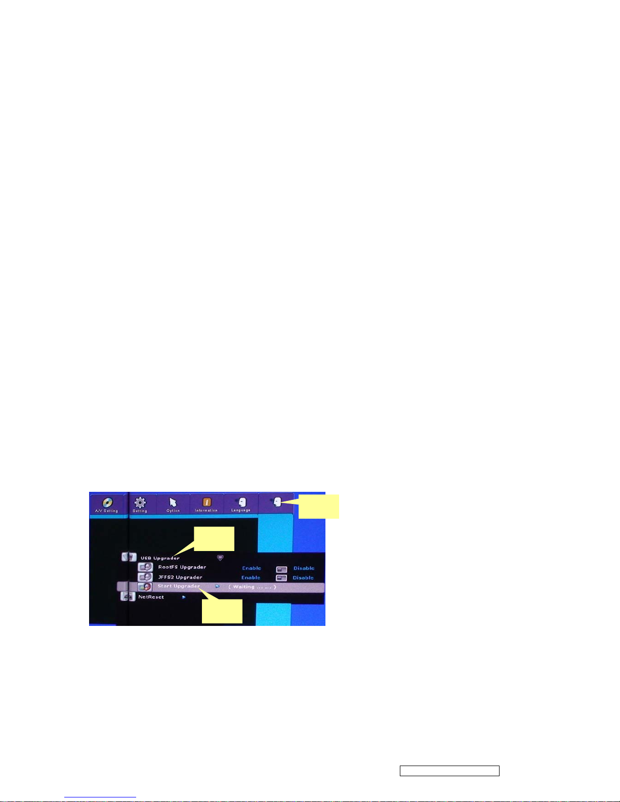
2.2 Upgrading Procedure
1) Give power supply to switch projector on.
2) Insert the USB Disk into the projector (copy the upgrading F/W document into it firstly.)
3) Enter the engineering mode.
4) Press Menu to exit.
5) Select the next item of “Language” to enter the upgrading mode . (“Language” is a hiding item
that can be seen only after entering the engineering mode and then exit successfully.)
6) Press button to select ”USB Upgrader”, and then press right button to search FW
document.
7) After finding the FW document, move highlight bar to ” Start Upgrade”.
8) Press right button to start upgrade procedure.
9) When complete the procedure, projector will turn off automatically. Unplug the power cord.
1
2
3
Confidential - Do Not Copy
ViewSonic Corporation
Pro8400
13
Page 17
3 Machine Disassembly and Replacement
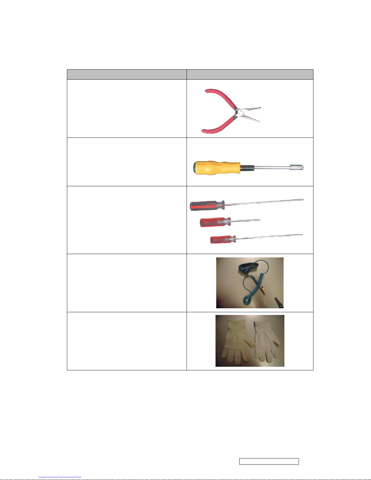
3.1 Tools
Item Photo
Long Nose Nipper
Hex Sleeves 5mm
Screw Bit(+):107
Screw Bit(+):101
Screw Bit(+):102
Anti-static wrist strap
Anti-static wrist gloves
Confidential - Do Not Copy
ViewSonic Corporation
Pro8400
14
Page 18

3.2 Disassembly Procedure
Warning
Put on the Static Electricity Ring when starting for repair.
Repair Environment suggest in Clean -room class 10000. Do not remove Optical
Engine or DMD panel outside the clean room. Please return the optical engine to
supplier if your repair condition can not meet the requirement.
While screwing or unscrewing screws, please keep the screwdriver straight. Keeping
screwdriver inclined will damage the screw holes.
Please turn off the power befo re replacing any parts.
Please wait for the projector lamp cooling down and turn off the power before changing
it. Never touch or hit the lamp module when replacing the lamp.
When you replace the projector lamp, never touch the new lamp with your bare hands.
The invisible residue left by the oil on your hands may shorten the lamp life. Use
lint-free gloves or finger cots are recommended.
Confidential - Do Not Copy
ViewSonic Corporation
Pro8400
15
Page 19

Step Figure Description
1
Press the power button to
shutdown the projector and
disconnect the power cord.
If the lamp is hot, please do not
start any procedure until the
projector lamp cools down.
Flip the projector and remove
the lens cover.
2
1. Flip the projector on the table.
2. Remove the screws
J1635-A010-0A*8 on the Bottom
cover as shown.
3
Rotate the Focus Ring by
forward sequence to take it off
from the unit.
J1635-A010-0A*8
Confidential - Do Not Copy
ViewSonic Corporation
Pro8400
16
Page 20

Step Figure Description
4
1. Disconnect the FFC cable
between top cover and main
board.
2. Raise the Top Cover carefully.
Note: Don’t allow to scratch
surface of the lens.
To avoid scratching, it would
better paste some film on it for
protection before raising the Top
Cover.
5
1. Remove four screws to lift up
the keypad board.
6
1. Remove all screws as shown
to remove the IO cover.
FFC Cable
J1635-3720-0A *4
J1635-C230-00*4
J1635-A632-01*2P0P35-2500-00*8
Confidential - Do Not Copy
ViewSonic Corporation
Pro8400
17
Page 21

Step Figure Description
7
1. Remove the three screws on
the metal sheet of Main Board.
2. Remove the metal sheet of
Main Board.
8
1. Show you what the connector
should be.
2. Remove all wires. (Including
the two fan modules.)
3. Remove two screws on the
Main Board.
4. Remove the Main Board.
9
1. Remove three screws as
shown.
2. Remove the three wires on
the audio board.
3. Remove the audio board.
P2535-7300-0A *3
P2535-7300-0A *2
P2535-7300-0A*3
Confidential - Do Not Copy
ViewSonic Corporation
Pro8400
18
Page 22

Step Figure Description
10
1. Loosen the two screws as
shown.
11
1. Loosen the two screws as
shown.
2. Remove the metal sheet of
Ballast.
Note
Note: 2 wires have been
connected to Ballast.
Disconnect these 2 wires before
remove the metal sheet.
J1635-3185-00
To La m p
To Power Board
J1635-3623-0A
J1635-D110-0A*2
Confidential - Do Not Copy
ViewSonic Corporation
Pro8400
19
Page 23

Step Figure Description
12
Release the four pillars by Long
Nose Nipper to remove the
Ballast.
13
1. Remove four screws on the
optical engine.
2. Remove the optical engine
module carefully.
14
1. Loosen all screws of the two
speakers and then remove them
away.
2. Loosen the screws on the
Power Board and then remove
the Power module from Bottom
Cover.
J1635-A491-0A*4
P2535-7300-0A*4
J1635-D420-0A
J1635-2045-00*4
Confidential - Do Not Copy
ViewSonic Corporation
Pro8400
20
Page 24

Step Figure Description
15
Loosen the two screws and
remove the lamp module from
optical engine.
Note: Those screws are
included in the Lamp module.
16
1. Loosen the two screws on
the OE Fan.
2. Remove the Fan.
3. Loosen the four screws on
DMD Board.
4. Remove the heat sink and
DMD Board.
17
Loosen one screw to remove
the metal sheet.
J1635-3660-0A *2
P2535-7300-0A *4
P2535-7300-0A
Confidential - Do Not Copy
ViewSonic Corporation
Pro8400
21
Page 25

Step Figure Description
18
Loosen the three screws to
remove the protective cover of
color wheel.
19
Loosen the two screws to
remove the color wheel module
gently.
20
1. Loosen the two screws on
the Zoom Ring.
2. Remove the Zo om Ring.
J1635-3188-00 *2
J1635-0780-0A *3
P5K35-0220-00 *2
Confidential - Do Not Copy
ViewSonic Corporation
Pro8400
22
Page 26

Step Figure Description
21
1. Loosen the four screws on
the Lens.
2. Remove the Lens carefully.
3.3 Assembly FAN Module
Step Figure
Description
1
Assemble Fan1(J2394-0143-01) and
Fan2 (J2394-0144-00 ):
1. Paste the Fan Pad (P4E38-1070-00)
on the middle of it.
2. Paste the Fan Sponge*4
(P4G38-1180-00) on the top and
bottom of it as picture shown.
P0335-7010-01*4
Fan Pad
Fan1 Fan2
Fan Sponge*4
Confidential - Do Not Copy
ViewSonic Corporation
Pro8400
23
Page 27

3.4 Disassembly Lamp Module
As the projector operates over time, the brightness of the projector lamp gra dually decreases
and the lamp becomes more susceptible to breakage. We recommend replacing the lamp if a
warning message is displayed.
Note:
The lamp is extremely hot right after turning off the projector. If you touch the lamp, you
may scald your finger. When you replace the lamp, wait for at least 45 minutes for the
lamp to cool down.
Wear protective gloves and eyeglasses when fixing or detaching the lamp.
Do not operate the lamp in proximity to paper, cloth, or other combustible material nor
cover it with such materials.
1. Turn off the projector.
2. If the projector is installed in a ceiling mount, remove it.
3. Unplug the power cord.
4. Loosen the screw in the side of the lamp cover and remove the cover.
5. Remove the screws from the lamp module, raise the handle, an d lift out the module.
6. Insert the new lamp module into the projector and tighten the screws.
7. Replace the lamp cover and tighten the screw.
8. Turn on the projector. If the lamp does not turn on after the warm-up period, try reinstalling the
lamp.
9. Reset the lamp hour. Refer to the “Information” menu.
Confidential - Do Not Copy
ViewSonic Corporation
Pro8400
24
Page 28

4 Troubleshooting and Verifying the Repair
This chapter provides technicians with electronic background how to maintain the product.
Moreover, you can get the appropriate operation to solve some complicated probl ems of
component repairing and professional problems.
4.1 Troubleshooting
Warning
Do not directly look into the lens to avoid eyesight damages.
The projector is equipped with ventilation holes (intake) and ventilation holes (exhaust). Do
not block or place anything near these slots, or internal heat build -up may occur, causing
picture degradation or damage to the projector.
Confirm Software and hardware
(1) Confirm FW version is the latest.
How to enter Engineering Mode?
-Open the Main menu and move the color bar to “Information” item, and then move down
the color bar to “Equivalent Lamp Hours” item, press the direction key following the actions
below:
Right once, left twice, right once; then you will enter the Engineering Mode. )
Note: This FW version is just for reference.
Confidential - Do Not Copy
ViewSonic Corporation
Pro8400
25
Page 29

(2) Confirm LED indicator
Note: Swapping modules that may be defective with others known to be good is generally an ideal way to
find the module responsible for the problem. A failure symptom is rarely caused by more than one module,
so you will not usually need to replace more than one to correct a particular failure. Whatever main board,
ballast, IR board, power board, lamp module or optical engine are all suitable to check by swapping
modules.
Confidential - Do Not Copy
ViewSonic Corporation
Pro8400
26
Page 30

Power Source Troubleshooting:
No Power
Source after
turning on
Replace AC
socket
Replace power
board or reinstall
Replace keypad
and FFC
Replace
power board
Replace
main board
OK
OK
OK
OK
NG
NG
NG
NG
Check 7 pin
Power output
Check
Safety Switch
Check AC socket
and connector
Check LED and
keypad FFC
Fan failure after
turning on
Reconnect fan
Replace fan
Replace
Main board
NG
NG
NG
OK
OK
Check
Main board
Check
Fan
Check fan
connection
Check
Fuse
OK
Replace fuse
NG
Confidential - Do Not Copy
ViewSonic Corporation
Pro8400
27
Page 31

Fail to light up
Refer to LED
indicator and follow
indicative actions
Replace
Lamp Module
Replace
Power board
Replace
Ballast
Replace
Main board
OK
OK
OK
OK
OK
NG
NG
NG
NG
NG
Check
Main board
Check Ballast
Check
Lamp life
Check LED
indication
Check PWR 380V
output
Replace
CW module
NG
Check CW
Rotation while power
on
No Volume
Replace
Speaker
Replace
Audio board
NG
NG
OK
Check
Audio board
Check
Speaker
Check
Main board
Replace
Main board
NG
OK
Confidential - Do Not Copy
ViewSonic Corporation
Pro8400
28
Page 32

Signal Troubleshooting
Computer
No Signal
Turn on
Source
Replace
Cable
Replace
Main board
OK
OK
NG
NG
NG
Check
Output signal
Check
Cable
Check
Source
Video
No Signal
Turn on
Source
Replace
Cable
NG
NG
NG
OK
OK
Check
Cable
Check
Source
Check
Main board
Replace
Main board
Confidential - Do Not Copy
ViewSonic Corporation
Pro8400
29
Page 33

Image abnormal
Adjust
Input signal
Replace
Main board
Replace
Optical Engine
OK
OK
OK
NG
NG
NG
Check
Optical Engine
Check input
cable and signal
setting
Power on
again and reset
OSD
Check
Main board
Color abnormal
Adjust
Input signal
Adjust Color
Wheel Index
Replace
Main board
NG
NG
NG
OK
OK
Check
Main board
Check Color
Wheel Index
Check input
cable and signal
setting
Replace
Optical Engine
OK
NG
Check
Optical Engine
Confidential - Do Not Copy
ViewSonic Corporation
Pro8400
30
Page 34

Operation Function Troubleshooting
Remote Control
Failure
Replace
Battery
Replace
Remote Control
Replace
IR
Replace
Main board
OK
OK
OK
NG
NG
NG
NG
Check
Main board
Check
Remote Control
Check
Battery Level
Check
IR
Button Failure
Replace Keypad
and FFC
Replace
Main board
NG
NG
OK
Check
Main board
Check
Keypad and FFC
Confidential - Do Not Copy
ViewSonic Corporation
Pro8400
31
Page 35

4.2 Verifying the Repair
After repairing projector (Dissembling and assembling projector), Repair center should verify
the quality of repaired unit.
(1) Check Logo
Check Logo is correct after power on projector.
(2) Signal test (Each I/O can functio n normally)
Connect all connector to the jacks one after the other to check whether each channel can
project normally.
I/O port Monitor In (VGA)
Test Equipment
Standard Pattern generator (Ex. Quantum data)
Signal format
1920*1080 60Hz
I/O port Video
Test Equipment
Standard Pattern generator (Ex. Quantum data) or DVD player
Signal format
NTSC
I/O port S-Video
Test Equipment
Standard Pattern generator or DVD player
Signal format
480i
I/O port USB
Confidential - Do Not Copy
ViewSonic Corporation
Pro8400
32
Page 36

Test Equipment
PC and Remote controller
Test method
1. Connect PC (laptop) VGA output to projector.
Set PC (laptop) output signal to projector
2. Connect projector USB to PC.
Press remote controller page up/down to scroll presentation file up and
down (ex Microsoft office series)
I/O port Audio input
Test Equipment
Connect audio input to audio output of DVD player
Signal format
480i
I/O port HDMI
Test Equipment
HDMI source device
Signal format
1080p
(3) Operation test
Buttons operation
Button description Test criteria
Power button
1. Mechanical motion (Up & Down) should be free from getting stuck
when pressing the button
2. Press “power” button and projector will switch on
Menu
1. Mechanical motion (Up & Down) should be free from getting stuck
when pressing the button.
2. Press Menu button can make projector function normally.
4-way button
1. Mechanical motion (Up & Down) should be free from getting stuck
when pressing the 4-way button.
2. Press 4-way button can be used to scroll through OSD (On -
Screen Display) menus and make adjustments.
Source
1. Mechanical motion (Up & Down) should be free from getting stuck
when pressing the button
2. Press Source button manually selects an input source
Foot adjuster operation
Foot adjuster. Test criteria
Foot adjuster button
Foot adjusters should stretch downward smoothly by pressing the foot
adjuster buttons on the two sides
Confidential - Do Not Copy
ViewSonic Corporation
Pro8400
33
Page 37

Zoom ring and Focus ring
Ring Test criteria
Zoom ring
Mechanical motion of rotating Zoom ring to the end of right and left by
hand should be free from getting stuck.
Focus ring
The feeling of rotating Focus ring to the end of right and left by hand
should free from seizing
(4) Image Quality
Projected image size: 60 inches (diagonal length)
Zoom ring: Adjust zoom ring to wide (Maximum projection size)
VGA
I/O port
Monitor In (VGA)
Test Equipment
Standard Pattern generator (Ex. Quantum data)
Signal format
1920*1080 60Hz
Projected image size
60” in diagonal length
Test Pattern
Test criteria
ANSI Brightness
Apparent color strip, bend and streak
corner on the projected image are not
allowable.
Confidential - Do Not Copy
ViewSonic Corporation
Pro8400
34
Page 38

Extreme Gray-Scale
--0 represents full black, 255 represents full
white.
--Distinguishing the gray from black at the
value of 32 and the gray from white at the
value of 239 easily are acceptable.
Circular Geometry, Cross hatch and
Dots
1. The four lines of outer frame should
not only be existent but also
distinguishable.
2. The dots in the square should be
distinguishable.
Scaled Text ( Resolution)
1. Rotate Zoom ring to wide mode
(Maximum projected image)
2. Fix projector to set diagonal length of
projected image to 60”.
3. Adjust focus ring to make resolution of
4 corners and center are balanced.
4. Check the characters should be
recognized easily.
5. Rotate Zoom ring to tele mode
(Minimum projected image)
6. Adjust focus ring to make resolution of
4 corners and center are balanced.
7. Check the characters should be
recognized easily.
Confidential - Do Not Copy
ViewSonic Corporation
Pro8400
35
Page 39

INFOCOMM SMPTE 133
1. The intervals of center thin white and
black bars should be distinct.
2. The squares around the small circle in
the center show the transition of full
white to full black.
S-Video
I/O port
S-Video
Test Equipment
Standard Pattern generator (Ex. Quantum data)&DVD player
Signal format
480i
Criteria
No apparent color deviation on the projected image
Video
I/O port
Video
Test Equipment
Standard Pattern generator (Ex. Quantum data)&DVD player
Criteria
No apparent color deviation on the projected image
HDMI
I/O port
HDMI
Test Equipment
HDMI source device
Signal format
1080p
Criteria
No apparent color deviation on the projected image nor abnormal
voice.
(5) Resolution
I/O port
VGA
Test Equipment
PC
Test Method
1. Rotate Zoom ring to wide mode (Maximum projected image)
2. Fix projector to set diagonal length of projected image to 60 ”.
3. Adjust focus ring to make resolution of 4 corners and center
are balanced.
4. Check the characters should be recognized easily.
5. Rotate Zoom ring to tele mode (Minimum projected image)
Confidential - Do Not Copy
ViewSonic Corporation
Pro8400
36
Page 40

6. Adjust focus ring to make resolution of 4 corners and center
are balanced.
7. Check the characters should be recognized easily.
(6) Front and Rear infrared sensor
Device
Front and Rear infrared
Test Equipment
Remote controller
Test method
1. Cover front sensor and operate remote controller to test rear
sensor
2. Cover rear sensor and operate remote controller to test front
sensor
(7) Brightness measurements
Test items
Brightness measurements
Test Equipment
Chroma automatic system (The alternative is CL -200)
Test method
Measure 9 points
Criteria
Marketing spec 20% off
(8) Cosmetic standard for repaired projector
Follow cosmetic standard for repair center.
Confidential - Do Not Copy
ViewSonic Corporation
Pro8400
37
Page 41

5 Adjustment / Alignment Procedure
5.1 Color Wheel Index Adjustment
(1) Open the image of 256-level RGB.
(2) Enter the engineering Mode, and then move down the color bar to “CW Index” item.
(3) Press the button (right or left) to adjust the value of CW Index.
(4) Notice the changing of color till the RGB colors are distinguishable.
NOTE:
1. The CW Index of each CW is not a ll the same.
2. Adjusting the CW Index till the R, G, B colors are distinguishable will be fine.
Confidential - Do Not Copy
ViewSonic Corporation
Pro8400
38
Page 42

5.2 ADC Calibration
(1)Open the image of Gray16.
(2) Enter the engineering Mode, and then move down the color bar to “ADC Calibration” item.
(3) Press right button to execute ADC Calibration. C olor deviation is unacceptable.
If the screen blinks once, and then back to search signal and at last search out the image of
Gray16, this indicates the calibration is successful.
Confidential - Do Not Copy
ViewSonic Corporation
Pro8400
39
Page 43

(4) Open the image of SMPTEbar.
(5) Move down the color bar to “YPbPr Cal. /Th. Lamp” item.
(6) Press right button to execute YPbPr Calibration. Color deviation is unacceptable.
If the screen blinks once, and then back to search signal and at last search out the image of
SMPTEbar, this indicates the calibration is successful.
Confidential - Do Not Copy
ViewSonic Corporation
Pro8400
40
Page 44

5.3 Keystone Adjustment
(1) At horizontal platform, adjust the projector foot to make platform level.
(2) And then enter the engineering mode, and then move down the color bar to “Keystone Cal.”
item.
(3) Press right button to adjust.
Confidential - Do Not Copy
ViewSonic Corporation
Pro8400
41
Page 45

6 Connector Information
This section provides each connector location on boards and function of each board. They will
be useful for your detecting the defective boards.
6.1 Main Board
Connector Description
No1 Connect to DMD Board
6.2 The backside of Main Board
No1
No2
No4
No6
No8
No9
No10
No11 No12
No3
No5
No7
No1
No13
No14
Confidential - Do Not Copy
ViewSonic Corporation
Pro8400
42
Page 46

Connector Description
No 1 Keypad control
No 2 FAN1
No 3 Color Wheel Sensor
No 4 Color Wheel control
No 5 /
No 6 Ground
No 7 Optical Engine Fan
No 8 Ignite signal connected to Ballast
No 9 Thermal switch
No 10 Main Board Power Supply
No 11 FAN2
No 12 Safety switch
No 13 Audio Board
No 14 /
6.3 Ballast Board
Connector Description
No 1 Lamp power supply
No 2 Ignite signal connected to Main board
No 3 High Voltage Power supply
No1
No2
No3
Confidential - Do Not Copy
ViewSonic Corporation
Pro8400
43
Page 47

6.4 Power Board
Connector Description
No 1 380V output for ballast
No 2 12V/5V output for Main board and Audio board
No1
No2
Confidential - Do Not Copy
ViewSonic Corporation
Pro8400
44
Page 48

7 FRU (Field Replaceable Unit) List
Introduction
This section is a list of all the FRU removal . Following the FRU table of contents is an enlarged
view of the entire projector, which shows the primary FRUs in the projector.
When working on the projec tor, use appropriate anti-static precautions such as anti -static mats,
wrist straps and grounded work surfaces. Failure to do this can destroy static -sensitive
components and make the product inoperable.
Confidential - Do Not Copy
ViewSonic Corporation
Pro8400
45
Page 49

7.1 Mechanical Drawing
4. IO Cover
1. Lamp Cover
2. Top Cover
3. Filter Cover
5. Main Board
7. Audio Board
6. Lens Cover
8. Lamp Module
9. Optical Engine
10. Left Speaker
15. Right Speaker
14. Fan2
16. B-IR Board
13. Lens Frame
12. F-IR Board
11. Fan1
17. Ballast
18. Power Board
19. Bottom Cover
20. Rear Foot
Confidential - Do Not Copy
ViewSonic Corporation
Pro8400
46
Page 50

ViewSonic Model Number: VS13647
Rev:1a
Item ViewSonic P/N Ref. P/N Description
Q’ty
1
C-00010583
P7U84-4520 Lamp Cover 1
2
C-00010758
P7W84-4500 Top Cover 1
3
C-00010588
P7U34-4620-00 Filter Cover 1
4
C-00010759
P7W84-4530 IO Cover 1
5
B-00010911
P7W84-7100 Main Board 1
6
C-00010589
P7U34-4540-99 Lens Cover 1
7
B-00010813
P7W47-3100 Audio Board 1
8
RLC-059
P7U84-2400 Lamp Module 1
9
E-00010674
P7W84-2200 Optical Engine 1
10
E-00010441
J2413-0111-00 Left Speaker 1
11
M-00008759
J2394-0143-01 Fan1 1
12
B-00008158
P3747-5101 F-IR Board 1
13
C-00010587
P7U34-4610-00 Lens Frame 1
14
M-00008760
J2394-0144-00 Fan2 1
15
E-00010440
J2413-0108-00 Right Speaker 1
16
B-00010719
P7U47-5101 B-IR Board 1
17
B-00010720
P7U84-9000 Ballast 1
18
B-00010717
P7U84-8100 Power Board 1
19
C-00010585
P7U84-4510 Bottom Cover 1
20
M-00008767
P7U38-1540-00 Rear Foot 2
EXPLODED PARTS LIST (Pro8400)
Confidential - Do Not Copy
ViewSonic Corporation
Pro8400
47
Page 51

7.2 Packing drawing
Confidential - Do Not Copy
ViewSonic Corporation
Pro8400
48
Page 52

Confidential - Do Not Copy
ViewSonic Corporation
Pro8400
49
Page 53

ViewSonic Model Number: VS13647
Rev:1a
Item ViewSonic P/N Ref. P/N Description
Q'ty
1
n/a
P7W38-5000-00 UL LB 1
2
n/a
J4238-R815-01 SERIAL LB 1
3
n/a
P2838-5001-00 WARNING LB 1
4
n/a
P1638-5007-00 LB 1
5
n/a
P1638-5010-00 LB 1
6
n/a
P1238-R504-00 LB 1
7
n/a
J4039-0082-00 BB BAG 1
8
P-00010782
P7U39-7004-00 EPE 1
9
n/a
P7U39-3000-00 POUCH 1
10
DC-00010799
P7W39-4000-00 QG 1
11
DC-00010800
P7W39-A000-00 CD 1
12
n/a
J2491-0008-02 BATTERIES 1
13
P-00008410
J4039-R157-01 PE.BAG 1
14
P-00010781
P7U39-7003-00 EPE-LEFT 1
15
P-00010780
P7U39-7002-00 EPE-RIGHT 1
16
P-00010870
P7W39-6000-00 CARTON 1
17
n/a
J4238-5006-00 LB 1
PACKING PART LIST (Pro8400)
Confidential - Do Not Copy
ViewSonic Corporation
Pro8400
50
Page 54

8 Maintenance
The projector needs proper maintenance. You should keep the lens clean as dust, dirt or spots
will project on the screen and diminish image q uality. If any other parts need replacing, contact
your dealer or qualified service personnel. When cleaning any part of the projector, always
switch off and unplug the projector first.
Warning:
Never open any of the covers on the projector. Dangerous electrical v oltages inside the projector
can cause severe injury. Do not attempt to service this product yourself. Refer all servicing to
qualified service personnel.
Cleaning the Lens
Gently wipe the lens with lens cleaning paper. Do not touch the lens with your hand s.
Cleaning the Projector Housing
Gently wipe with a soft cloth. If dirt and stains are not easily removed, use a soft cloth damped
with water, or water and neutral detergent, and wipe dry with a soft, dry cloth.
Cleaning the Filter Cover
The filter cover, which is located at the side of the projector, should be cleaned after every 100
hours of use. If it is not cleaned periodically, it can become clogged with dust and prevent the
projector from being ventilated properly. This can cause over heating and damage the projector.
To clean the filter cover:
1. Switch the projector off and unplug the AC power
cord from the wall socket.
2. Remove the filter cover as the
illustration shown.
3. Clean the filter cover.
To clean the filter cover, you are advised to use a
small vacuum cleaner designed for computers
and other office equipment.
If the filter cover is torn, replace it.
4. Replace the filter cover.
5. Attach the filter cover.
6. Plug the power back into the projector.
Confidential - Do Not Copy
ViewSonic Corporation
Pro8400
51
Page 55

Appendix A: RS-232 Command and Configuration
Baud Rate: 19200 Parity Bit: none
Data Bit: 8 Stop Bit: 1 Assign Port: COM1
Confidential - Do Not Copy
ViewSonic Corporation
Pro8400
52
Page 56

Confidential - Do Not Copy
ViewSonic Corporation
Pro8400
53
Page 57

Appendix B: IR Control Code
Confidential - Do Not Copy
ViewSonic Corporation
Pro8400
54
Page 58

Appendix C: How to reset the Lamp Hours
(1) Press “Menu” button to open the Main menu.
(2) Move color bar to “Information” item.
(3) Move down the color bar to “ Equivalent Lamp Hours Reset” item.
(4) Press “enter” button to enter sub-menu.
(5) Press left button to select “yes” to reset Lamp Hours.
(6)Then the Lamp Hours would reset to 0 hours.
Confidential - Do Not Copy
ViewSonic Corporation
Pro8400
55
Page 59

ViewSonic Model Number:VS13647
Serial No. Prefix:S8E
Rev.: 1a
Item Categor
y
Part Name Description ECR/ECNViewSonic P/
N
Ref. P/N Remar
k
1 LAM
P
LAMP_MODULE_280W_SPARE PART_VPD-X7000_ROH
S
RLC-059 P7U84-240
0
If Q'ty = 1000, price = 80
2 Remote Controlle
r
REMOTE CONTROL_VIEWSONIC_VPD-W6004_WITHOUT/B_ROH
S
A-00008988
J8947-0310-00
3 Power Cord POWER CORD (AUSTRALIA).
_
(SAA)YP-35/YC-12_YUNG LI_ROH
S
A-00008060
J2552-0053-00
4 Power Cord POWER CORD(CHINA).
_
YP-03/YC-12_YUNG LI_ROH
S
A-00008056
J2552-0106-00
5 Power Cord POWER CORD(EUROPE).
_
YP-22/YC-12_YUNG LI_ROH
S
A-00008057
J2552-0107-00
6 Power Cord POWER CORD(UK).
_
YP-61/YC-12_YUNG LI_ROH
S
A-00008058
J2552-0108-00
7 Power Cord POWER CORD (SOUTH AFRICA).
_
YP-80/YC-12_YUNG LI_ROH
S
A-00008233
J2552-0056-01
8 Power Cord POWER CORD(USA).
_
UL(YP-12/YC-12)_YUNG LI_ROH
S
A-00008059
J2552-0109-00
9 Power Cord POWER CORD (ARGENTINA)
_
SP-852+IS-14_I-SHENG_ROH
S
A-00008585
J2552-0263-00
10 Si
g
nal Cable HDMI 19P TO 19P CABLE_L1800_VIEWSONIC_P2650-05_PAN_ROH
S
CB-00008572
J2552-0171-00
11 RS232 Cabl
e
DB9P TO DB9P CABLE_L1500_P35251A-05_PAN_ROH
S
CB-00009062
J2552-0208-00
12 Adapter VGA-15P-6P CABLE
_
P4724-08_PAN_ROH
S
CB-00008906
J2552-0212-00
13 Si
g
nal Cable VGA-15P CABLE_P3842-06_PAN_ROH
S
CB-00008710
J2552-0072-03
14 Main Board MAIN
_
DIP_PCB_ASY_SPARE PARTS_VPD-W6002_ROH
S
B-00010911
P7W84-7100
15
Power Boar
d
POWER BOARD_SPARE PARTS_VPD-X7000_ROH
S
B-00010717
P7U84-810
0
16
Ke
y
Pa
d
KEYPAD_DIP_PCB_ASY_VPD-W6001_ROH
S
B-00010718
P7U47-710
0
17
IR Boar
d
FIR_DIP_PCB_ASY_PD-X702_ROHS (Front IR
)
B-00008158 P3747-5101
18
IR Boar
d
REAR IR_DIP_PCB_ASY_VPD-W6001_ROHS (Rear IR
)
B-00010719 P7U47-5101
19
Ballast
OSRAM-BALLAST-280W
_
SPARE PART_VPD-X7000_ROH
S
B-00010720
P7U84-900
0
20
I/O Boar
d
AUDIO_DIP_PCB_ASY_VPD-W6002_ROH
S
B-00010813
P7W47-3100
21
DMD Boar
d
DMD_DIP_PCB_ASY_VPD-W6002_ROH
S
B-00010814
P7W47-6100
22
Sensor Boar
d
CW SENSOR_DIP_PCB_ASY_VPD-W6002_ROHS (CW Sensor Board
)
B-00010723 P7W47-5100
23 Lamp Cove
r
LAMP COVER_SPARE PARTS_VPD-X7000_ROH
S
C-00010583 P7U84-452
0
24 Top Cove
r
TOP COVER_SPARE PARTS_VPD-W6002_ROH
S
C-00010758 P7W84-4500
25
Bottom Cove
r
BOTTOM COVER_SPARE PARTS_VPD-X7000_ROH
S
C-00010585 P7U84-451
0
26
I/O Cove
r
I/O COVER_SPARE PARTS_VPD-W6002_ROH
S
C-00010759 P7W84-4530
27
Lens Cove
r
LENS-FRAME-BOTTOM_VPD-X7000_05000-0050-00_NO PAINTING_ROH
S
C-00010587 P7U34-4610-0
0
28
Filter Cove
r
FILTER-HOLDER_VPD-X7000_05000-0050-00_NO PAINTING_ROH
S
C-00010588 P7U34-4620-0
0
29
Lens Cove
r
LENS-COVER_VPD-X7000_05000-0050-00_FOR PAINTING_ROH
S
C-00010589 P7U34-4540-99
30 Wire
FFC CABLE
_
A20200C3344NB_ENTERY_0.5PITCH_20PIN_L200MM_ROHS(keypad board to MB
CB-00009764 J2591-0140-00
31 Wire
FFC CABLE
_
A20110D3344NB_ENTERY_0.5PITCH_20PIN_L110MM_ROHS(audio board to MB
)
CB-00009765 J2591-0139-00
32 Wire
WIRE CON-CON
_
1102003-344_MSK_4PIN_L100MM_1571#28_ROHS(B-IR board to MB
)
CB-00009766
J2595-0518-00
33 Wire
WIRE CON-CON
_
1102003-345_MSK_4PIN_L260MM_1571#28_ROHS(F-IR board to MB
)
CB-00009767
J2595-0519-00
34 Wire
WIRE SW-CON
_
1102003-201_MSK_2PIN_L25MM_1007#26_ROHS (Lamp door switch
)
CB-00009768
J2595-0344-00
35 Wire
WIRE CON-CON
_
1102003-200_MSK_10+4PIN-2*8PIN_L115/185MM_1007#24/#26_ROHS(power board to MB an
d
CB-00009769
J2595-0342-00
36 Wire
WIRE CON-CON
_
1102003-187_MSK_5PIN_L150MM_1571#28_ROHS(ballast to MB
)
CB-00009770
J2595-0328-00
37 Wire
WIRE TERMINAL-CON
_
103AP-110330-10N001_SEMITEC_ROH
S
CB-00009771
J2595-0489-00
38 Wire
WIRE CON-THERMAL FUSE
_
01800171R_AVERTRONICS_ROHS(thermal switch
)
CB-00009772
J2595-0343-00
39 Wire
WIRE CON-CON
_
1102003-98_MSK_2PIN_L140MM_1015#22_ROHS(power board to ballast
)
CB-00008469
J2595-0218-00
40 Wire
TERMINAL WIRE
_
1102003-239_MSK_1PIN_L70MM_BLACK_1015#16_ROH
S
CB-00009773
J2596-0016-00
41 Wire
WIRE LAMP-BALA
(
MPD-X5501)_01800167R_AVERTRONICS_2PIN_L185MM_3239V#20_ROHS(Ballast to Lam
p
CB-00009774
J2595-0336-00
42 Wire
WIRE CON-CON 1102003-182 MSK 4PIN L120MM 1571#28 ROHS
(
color wheel to main board
)
CB-00009053
J2595-0325-00
43
Q
ucik Start Guide
(QS
QG_
VIEWSONIC_VPD-W6002_GLOBAL_ROH
S
DC-00010799
P7W39-4000-00
44 User's Guide (DVD R
O
CD ROM_VIEWSONIC_VPD-W6002_GLOBAL_ROH
S
DC-00010800
P7W39-A000-00
45
Label / Sticke
r
CARTON LB_VIEW SONIC_PJ557D_GLOBAL_ROHS(for China
)
DC-00008672 P0N38-5013-00
46
O
p
tical Engine OPTICAL ENGINE_SPARE PART_WITHOUT LAMP_VPD-W6002_ROH
S
E-00010674 P7W84-2200
47
Color Wheel
COLORWHEEL
_
SPARE PARTS_VPD-X7000_ROH
S
E-00010436 P7U84-260
0
48 Lens LENS ASY_SPARE PARTS_VPD-X7000_ROH
S
E-00010437 P7U84-620
0
49 DMD Chip DMD-ATYPE-0.65-1080P_VPD-W6004_ROH
S
E-00010529 P7Y84-7010
50 Li
g
ht Pipe LIGHT TUNNEL_BPD-W6102_ROH
S
E-00010530 P8D84-7620
51 Speake
r
SPEAKER_P52KUG06X-7JS1_VECO_ROHS (Right
)
E-00010440 J2413-0108-00
52 Speake
r
SPEAKER_P52KUG06X-7JS2_VECO_ROHS (Left
)
E-00010441 J2413-0111-00
53 Screw HEXAGON-HEAT-BOLT
_
TPD-X570_00_ROH
S
HW-00009484P0P35-2500-00
54 Screw SCREW
_TP_4_10_A_
2.5_D=6.8_WH-ZN_NONE_ROH
S
HW-00009485 J1635-A010-0
A
55 Screw SCREW_M_3_5_A_1.5_D=4.5_BLACK_NONE_ROH
S
HW-00009486J1635-A342-00
56 Screw SCREW
_TP_3_8_A_2_
D=5.3_BLACK_NONE_ROH
S
HW-00009487J1635-A632-01
57 Screw SCREW
_M_3_5_A_2_
D=5.3_BLACK_NONE_ROH
S
HW-00009488 J1635-C230-00
58 Screw SCREW-MB-670H
_
EMS-DX540_01_NO PAINTING_ROH
S
HW-00009489P2535-7300-0
A
59 Screw SCREW-WASHER_TP_3_6_D_2.6_D=8.5_ZN_NONE_SUS_ROH
S
HW-00009490J1635-3623-0
A
60 Screw SCREW_M_2.0_3.5_E_0.5_D=4.0_WH-ZN_NONE_ROH
S
HW-00009491 J1635-3185-00
61 Screw SCREW
_M_3_5_E_1_
D=6_WH-ZN_NL_ROH
S
HW-00009492J1635-D110-0
A
62 Screw SCREW-WASHER_TP_2_4_D_1_D=3.2_ZN_NONE_SUS_ROH
S
HW-00009493
J1635-3720-0
A
63 Fan FAN-3000_EE92251S1_3PIN_SUNON_ROHS (Left
)
M-00008759 J2394-0143-01
64 Fan FAN-3400
_
EF92251BX_3PIN_SUNON_ROHS (Right
)
M-00008760 J2394-0144-00
65 Fan SLEEVE FAN
_
MF50201V1_SUNON_ROHS (Lamp
)
M-00008761 J2394-0145-01
66
S
pong
e FAN-FILTER_VPD-X7000_ROH
S
M-00008764
P7U38-1650-0
0
67
S
pong
e FAN-FILTER-LOWER_VPD-X7000_ROH
S
M-00008765
P7U38-1670-0
0
68
S
pong
e
FAN SPONGE
_
MPD-X5501_ROHS (Fan sponge
)
M-00008766 P4G38-1180-00
69 Pa
d
FAN PAD_TPD-X5500_ROH
S
M-00008390 P4E38-1070-00
70
Rin
g
ZOOM-RING_VPD-X7000_05002-2019-00_FOR PAINTING_ROH
S
M-00008762 P7U34-4580-99
71
Rin
g
FOCUS-RING_VPD-X7000_05002-2019-00_NO PAINTING_ROH
S
M-00008763 P7U34-4570-99
72 Foo
t
RUBBER-FOOT_VPD-X7000_ROH
S
M-00008767 P7U38-1540-0
0
73 Carton CARTON_VIEWSONIC_VPD-W6002_GLOBAL_ROH
S
P-00010870 P7W39-6000-00
74 Foa
m
EPE_NO_VPD-X7000_LEFT_ROH
S
P-00010780 P7U39-7002-0
0
75 Foa
m
EPE_NO_VPD-X7000_RIGHT_ROH
S
P-00010781 P7U39-7003-0
0
76 Foa
m
EPE_NO_VPD-X7000_TOP_ROH
S
P-00010782 P7U39-7004-0
0
77 Plastic Ba
g
PE BAG._NO BRAND_298MM*190MM_ROH
S
P-00008794 J4039-R184-01
78 Plastic Ba
g
PE BAG._NO BRAND_GLOBAL_ROH
S
P-00008410 J4039-R157-01
Remark 1:
Above listed items are examples, supplier can expand the rows to add more necessar
y
items.
Remark 2:
N
otice: 1. For some special parts, some photos for identification purpose may be asked by reques
t
2. For all internal cables, there must be some wordings on the "Description" column about where the cable is used (connecting to which two parts)
3. All internal cables/wires should be put in the "Cables" cate
gory
4. All external cables should be put in the "Accessories" categor
y
5. Parts relationship (Main/Second source or 1/2/3/4) should be added in the "Compatibility" column
6. If an
y
part for certain product isn't listed in the form, supplier/PE can add it themselves and keep the part name unified.
Hardware:
[Screw, Bracket,
Hinge]
PC Board
Assembly: [All
PCBA]
Accessories:
[Adapter, Remote
Controller, Power
Cord, External
Cables]
Electronic
Components:
[Optical Engine,
Speaker, Color
Wheel]
Cabinets:
[Front Bezel, All
Covers, Base
Assembly]
Cables: [All
internal
Cables/wires]
RECOMMENDED SPARE PARTS LIST (PRO8400-1W)
Miscellaneous:
[Switch, Fan,
Rubber Foot,
Logo]
Packing Material:
[Box, Foam, Bags]
Documentation:
[Quick Start
All revised RSPLs with newly added items or any change made should be highlighted and correlated with the ECN/ECR approved by ViewSonic Corporation. This is to eliminate repeated cross checks of
Confidential - Do Not Copy
ViewSonic Corporation
Pro8400
56
9 Recommended Spare Parts List
Page 60

* Reader’s Response*
Dear Readers:
Thank you in advance for your feedback on our Service Manual, which allows continuous improvement
of our products. We would appreciate your completion of the Assessment Matrix below, for return to
ViewSonic Corporation.
Assessment
A. What do you think about the content of this Service Manual?
Unit Excellent Good Fair Bad
1. System Introduction
2. Firmware Upgraded Flow
3. Machine Disassembly and Replacement
4. Troubleshooting and Verifying the Repair
5. Adjustment / Alignment Procedure
6. Connector Information
B.
Are you satisfied with this Service Manual?
Item Excellent Good Fair Bad
1. Service Manual Content ʳʳʳʳ
2. Service Manual Layout ʳʳʳʳ
3. The form and listing ʳʳʳʳ
C. Do you have any other opinions or suggestions regarding this service manual?
Reader’s basic dada:
Name: ʳ Title: ʳ
Company: ʳ
Add: ʳ
Tel: ʳ Fax: ʳ
E-mail: ʳ
After completing this form, please return it to ViewSonic Quality Assurance in the USA at facsimile
1-909-839-7943.
7. FRU (Field Replaceable Unit) List
8. Maintenance
9. Recommended Spare Parts List
Confidential - Do Not Copy
ViewSonic Corporation
Pro8400
57
 Loading...