

Page 1

LS700-4KP
DLP Projector
User Guide
IMPORTANT: Please read this User Guide to obtain important information on installing
and using your product in a safe manner, as well as registering your product for future
service. Warranty information contained in this User Guide will describe your limited
coverage from ViewSonic Corporation, which is also found on our web site at http://
www.viewsonic.com in English, or in specic languages using the Regional selection
box in the upper right corner of our website. “Antes de operar su equipo lea cu
idadosamente las instrucciones en este manual”
Model No. VS17455
Page 2

Compliance Information
FCC Statement
This device complies with part 15 of FCC Rules. Operation is subject to the following
two conditions: (1) this device may not cause harmful interference, and (2) this device
must accept any interference received, including interference that may cause undesired
operation.
This equipment has been tested and found to comply with the limits for a Class B digital
device, pursuant to part 15 of the FCC Rules. These limits are designed to provide
reasonable protection against harmful interference in a residential installation. This
equipment generates, uses, and can radiate radio frequency energy, and if not installed
and used in accordance with the instructions, may cause harmful interference to radio
communications. However, there is no guarantee that interference will not occur in a
particular installation. If this equipment does cause harmful interference to radio or
television reception, which can be determined by turning the equipment off and on, the
user is encouraged to try to correct the interference by one or more of the following
measures:
● Reorient or relocate the receiving antenna.
● Increase the separation between the equipment and receiver.
● Connect the equipment into an outlet on a circuit different from that to which the
receiver is connected.
● Consult the dealer or an experienced radio/TV technician for help.
Warning: You are cautioned that changes or modications not expressly approved by
the party responsible for compliance could void your authority to operate the equipment.
For Canada
CAN ICES-3 (B)/NMB-3(B)
CE Conformity for European Countries
The device complies with the EMC Directive 2014/30/EU and Low Voltage
Directive 2014/35/EU.
Following information is only for EU-member states:
The mark is in compliance with the Waste Electrical and Electronic
Equipment Directive 2012/19/EU (WEEE).
The mark indicates the requirement NOT to dispose the equipment
including any spent or discarded batteries or accumulators as unsorted
municipal waste, but use the return and collection systems available.
If the batteries, accumulators and button cells included with this
equipment, display the chemical symbol Hg, Cd, or Pb, then it means
that the battery has a heavy metal content of more than 0.0005%
Mercury or more than, 0.002% Cadmium, or more than 0.004% Lead.
i
Page 3

Important Safety Instructions
1. Read these instructions.
2. Keep these instructions.
3. Heed all warnings.
4. Follow all instructions.
5. Do not use this unit near water.
6. Clean with a soft, dry cloth.
7. Do not block any ventilation openings. Install the unit in accordance with the
manufacturer’s instructions.
8. Do not install near any heat sources such as radiators, heat registers, stoves, or
other devices (including ampliers) that produce heat.
9. Do not defeat the safety purpose of the polarized or grounding-type plug. A
polarized plug has two blades with one wider than the other. A grounding type plug
has two blades and a third grounding prong. The wide blade and the third outlet,
consult an electrician for replacement of the obsolete outlet.
10. Protect the power cord from being walked on or pinched particularly at plugs. Be
sure that the power outlet is located near the unit so that it is easily accessible.
11. Only use attachments/accessories specied by the manufacturer.
12. Use only with the cart, stand, tripod, bracket, or table specied by the
manufacturer, or sold with the unit. When a cart is used, use caution
when moving the cart/unit combination to avoid injury from tipping over.
13. Unplug this unit when unused for long periods of time.
14. Refer all servicing to qualied service personnel. Servicing is required when the
unit has been damaged in any way, such as: if the power-supply cord or plug is
damaged, if liquid is spilled onto or objects fall into the unit, if the unit is exposed to
rain or moisture, or if the unit does not operate normally or has been dropped.
ii
Page 4

Declaration of RoHS2 Compliance
This product has been designed and manufactured in compliance with Directive
2011/65/EU of the European Parliament and the Council on restriction of the use of
certain hazardous substances in electrical and electronic equipment (RoHS2 Directive)
and is deemed to comply with the maximum concentration values issued by the
European Technical Adaptation Committee (TAC) as shown below:
Substance Proposed Maximum
Concentration
Lead (Pb) 0.1% < 0.1%
Mercury (Hg) 0.1% < 0.1%
Cadmium (Cd) 0.01% < 0.01%
Hexavalent Chromium (Cr6+) 0.1% < 0.1%
Polybrominated biphenyls (PBB) 0.1% < 0.1%
Polybrominated diphenyl ethers (PBDE) 0.1% < 0.1%
Bis (2-ethylhexyl) phthalate (DEHP) 0.1% < 0.1%
Butyl benzyl phthalate (BBP) 0.1% < 0.1%
Dibutyl phthalate (DBP) 0.1% < 0.1%
Diisobutyl phthalate (DIBP) 0.1% < 0.1%
Actual Concentration
Certain components of products as stated above are exempted under the Annex III of
the RoHS2 Directives as noted below:
Examples of exempted components are:
1. Lead in glass of cathode ray tubes.
2. Lead in glass of uorescent tubes not exceeding 0.2% by weight.
3. Lead as an alloying element in aluminium containing up to 0.4% lead by weight.
4. Copper alloy containing up to 4% lead by weight.
5. Lead in high melting temperature type solders (i.e. lead-based alloys containing
85% by weight or more lead).
6. Electrical and electronic components containing lead in a glass or ceramic other
than dielectric ceramic in capacitors, e.g. piezoelectronic devices, or in a glass or
ceramic matrix compound.
iii
Page 5

Copyright Information
Copyright © ViewSonic® Corporation, 2017. All rights reserved.
Macintosh and Power Macintosh are registered trademarks of Apple Inc.
Microsoft, Windows, Windows NT, and the Windows logo are registered trademarks of
Microsoft Corporation in the United States and other countries.
ViewSonic, the three birds logo, OnView, ViewMatch, and ViewMeter are registered
trademarks of ViewSonic Corporation.
VESA is a registered trademark of the Video Electronics Standards Association.
DPMS and DDC are trademarks of VESA.
PS/2, VGA and XGA are registered trademarks of International Business Machines
Corporation.
Disclaimer: ViewSonic Corporation shall not be liable for technical or editorial errors or
omissions contained herein; nor for incidental or consequential damages resulting from
furnishing this material, or the performance or use of this product.
In the interest of continuing product improvement, ViewSonic Corporation reserves the
right to change product specications without notice, Information in this document may
change without notice.
No part of this document may be copied, reproduced, or transmitted by any means, for
any purpose without prior written permission from ViewSonic Corporation.
Product Registration
To fulll possible future product needs, and to receive additional product information as
it becomes available, please visit your region section on ViewSonic’s website to register
your product online.
Registering your product will best prepare you for future customer service needs.
Please print this user guide and ll the information in the “For Your Records” section.
For additional information, please see the “Customer Support” section in this guide.
For Your Records
Product Name: LS700-4KP
ViewSonic DLP Projector
Model Number: VS17455
Document Number: LS700-4KP_UG_ENG Rev.1A
Serial Number: ________________________________________________
Purchase Date: ________________________________________________
Product disposal at end of product life
The lightsource in this product contains mercury which can be dangerous to you and the
environment. Please use care and dispose of in accordance with local, state or federal
laws.
ViewSonic respects the environment and is committed to working and living green.
Thank you for being part of Smarter, Greener Computing. Please visit ViewSonic’s
website to learn more.
USA & Canada: http://www.viewsonic.com/company/green/recycle-program/
Europe: http://www.viewsoniceurope.com/uk/support/recycling-information/
Taiwan: http://recycle.epa.gov.tw/
iv
Page 6

Table of Contents
Key safety instructions .... 1
Introduction ....................... 3
Projector features ...................................... 3
Shipping contents ...................................... 4
External appearance of the projector ........ 5
Device control and functions ..................... 6
Projector Positioning ..... 11
Choosing a location ..................................11
Projection Dimension............................... 12
Connection ...................... 13
Connect to the computer or monitor ........ 14
Connecting to Video source devices ....... 15
Connecting to HDMI devices ................... 16
Connecting to composite video source
devices .................................................... 16
Audio playback with the projector ............ 16
Perform keystone correction.................... 29
Using the CEC function ........................... 30
Smart energy-saving ............................... 30
Light Source Mode .................................. 31
Operations at high altitudes ..................... 31
Hiding the image...................................... 31
Optimize images in user mode ................ 32
Fine-tuning of image quality in user
modes ...................................................... 33
Adjust Gamma ......................................... 34
Color Management .................................. 35
Fine-tuning of image in user modes ........ 36
Select the aspect ratio ............................. 37
About the aspect ratio.............................. 37
Control the projector with the web
browser .................................................... 40
About Crestron e-Control® ....................... 43
Using the projector under standby
mode........................................................ 45
Switch off the projector ............................ 46
Operation ......................... 17
Activate the projector ............................... 17
Using the menus...................................... 18
Use basic settings ................................... 19
Use Network setting ................................ 20
Use Advanced settings ............................ 21
Use Information ....................................... 22
Use Firmware upgrade ............................ 23
Use Image settings .................................. 24
Use Advanced settings (in signal source
mode) ...................................................... 25
Switching input signal .............................. 26
Changing HDMI input settings ................. 27
Adjusting the projected image ................. 28
Menu operations ...................................... 47
Maintenance .................... 53
Care of the projector ................................ 53
LED Indicator ........................................... 54
Troubleshooting ............. 55
Specications ................. 56
Projector specications............................ 56
Fuse specications .................................. 56
Dimensions .............................................. 57
Ceiling mount installation......................... 57
Timing chart ............................................. 58
v
Page 7

Copyright information .... 62
Copyright ................................................. 62
Disclaimer ................................................ 62
Appendix ......................... 63
IR control table ........................................ 63
Address Code .......................................... 64
RS232 command table ............................ 65
vi
Page 8

Key safety instructions
Design and testing of your projector have been carried out in compliance with the
latest safety standards for information technology (IT) devices. However, it is extremely
important for you to follow the instructions provided in this manual and product labels
during use to ensure user safety.
Safety Instructions
● Please read through this manual before using the projector. Save it for future
reference.
● Do not look straight at the projector lens during operation. The intense light
beam may damage your eyes.
● Refer servicing to qualied service personnel.
● Always open the lens shutter or remove the lens cap when the projector light
source has been switched on.
● In some areas there may be line voltage instability. This projector is designed to
operate safely within a mains voltage between 100 to 240 volts AC, but could fail if
power cuts or surges of ±10 volts occur. In areas where the mains voltage may
uctuate or cut out, it is recommended that you connect your projector through
a power stabilizer, surge protector or uninterruptible power supply (UPS).
● Do not block the projection lens with any objects when the projector is under
operation as this could cause the objects to become heated and deformed or even
cause a re.
● Do not place the projector on an unstable cart, stand, or cable. The product may fall
and sustain serious damage.
● Do not attempt to disassemble this projector. The projector contains high voltage
parts that may cause electrocution or death when it comes in contact with the human
body. Under no circumstances should you ever undo or remove any other covers.
Refer servicing to qualied service personnel.
● Do not place this projector in any of the following environments.
- Space that is poorly ventilated or conned. Allow at least 50 cm clearance from
walls and ensure free ow of air around the projector.
- Locations where temperatures may become excessively high, such as the inside of
a car with all windows rolled up.
- Locations that are too humid, dusty, or smoky may contaminate optical
components, shortening the projector's life span and darkening the image.
- Locations near re alarms
- Locations where temperature exceeds 40°C/104°F.
- Locations with altitudes greater than 5,000 m (16,500 feet).
1
Page 9

● Do not block the ventilation holes. If the ventilation holes are seriously obstructed,
overheating inside the projector may result in a re.
- Do not place this projector on a blanket, bedding or any other soft surface.
- Do not cover this projector with a cloth or any other item.
- Do not place ammable items near the projector.
● Do not step on the projector or place any objects upon it. These acts may damage the
projector itself as well as cause accidents or personal injury.
● Do not place liquids near or on the projector. Liquids spilled into the projector may
cause damage. If the projector does become wet, please unplug the power cable
from the power socket and contact your local repair center for repairs.
● This product can be mounted on a ceiling suspension mount for back projection.
Use only ceiling suspension mounts that meet the relevant requirements and ensure that
the installation is safe.
● When the projector is under operation, you may sense some heated air and odor from
its ventilation grill. It is a normal phenomenon and not a product defect.
● Do not use the safety lever during transport or installation purposes. The safety lever
should only be used with the anti-theft cables sold on the market.
Safety instructions for ceiling mounting of the projector
We hope you to have a pleasant user experience with our projector. This is why we’re
bringing these safety reminders to your attention to prevent possible damage to person
and property.
If you intend to mount your projector on the ceiling, we strongly recommend that you use a
suitable projector ceiling mount kit and ensure it is securely and safely installed.
There may be safety risks if you fail to use an appropriate projector ceiling mounting kit.
Use of inappropriate connectors or screws of the wrong specications or length may cause
the projector to fall from the ceiling.
You can purchase a projector ceiling mounting kit from the projector dealer. We
recommend buying a safety harness in addition to the mounting kit. The harness should be
securely connected to the anti-theft locking groove on the projector as well as the base of
the ceiling mounting support. This will provide additional protection in case the connectors
of the mounting support becoming loose.
Like handling any bright light sources, do not directly look at the
light beam.
2
Page 10

Introduction
Projector features
The projector integrates high-performance optical engine projection and a user-friendly
design to deliver high reliability and ease of use. The projector offers the following
features:
● The color mode provides different options designed for different projectors.
● Compatible with NTSC, PAL, SECAM and HDTV
● D-Sub 15-pin terminal can be connected to analog video
● Equipped with HDMI connection, supports HDCP
● Multi-language On-Screen Display (OSD) menus
● Digital keystone correction to correct distorted images
● RS-232 interface supports serial control
● The power saving mode reduces the lamp power consumption by up to 30% when no
input signal is detected for a set length of time.
● Presentation timer for better control of time during presentations
● 3D Ready supported
● Color management can be used to adjust the color according to your preferences
● The screen type correction function can be projected on a variety of pre-set color
surfaces
● Switching among Normal, Power Saving and CUSTOM Modes reduces power
consumption.
● Quick Auto Search speeding up the signal detecting process
● Activating Power Saving mode will bring power consumption to below 0.5W
● “Network Settings” allows management on the projector state by using a remote
computer.
● One-key auto-adjustment to display the best picture quality (applicable to the analog
signal only)
● Provides Color Management adjustments for digital / video displays
3
Page 11

Shipping contents
Carefully unpack the product and check that you have all of the items shown below. If
any of these items are missing, please contact your place of purchase.
Standard accessories
The supplied accessories will be suitable for your region, and may differ from those illustrated.
Projector Power cord
VGA cable Remote Control and Batteries Quick Start Guide
4
Page 12
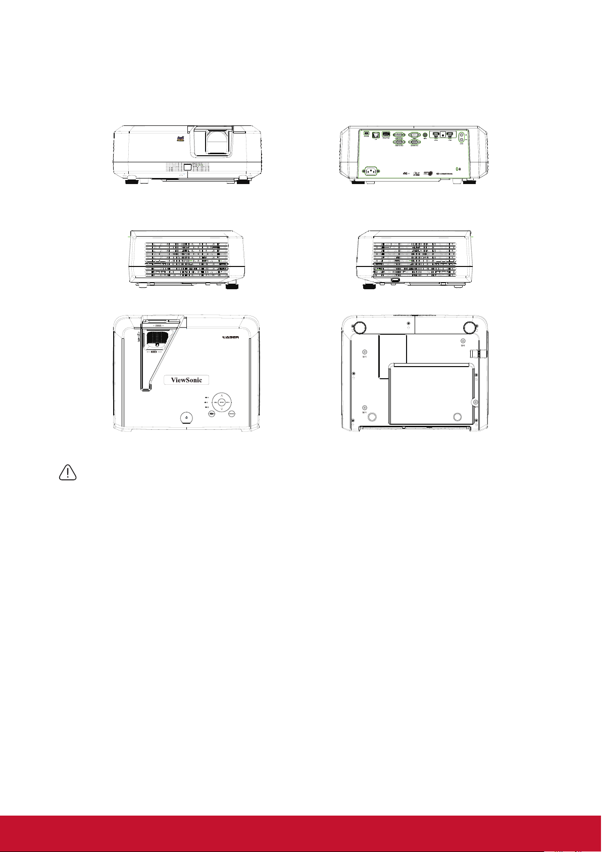
External appearance of the projector
Front/Rear
Side
Top/Bottom
Warning
● This equipment must be grounded.
● You may add power interruption devices in the xed wiring or plug in the power cable to a nearby socket for
convenience. If failures or errors occur during equipment operations, use the power interruption device to cut
the power or unplug the power cable from the socket.
5
Page 13
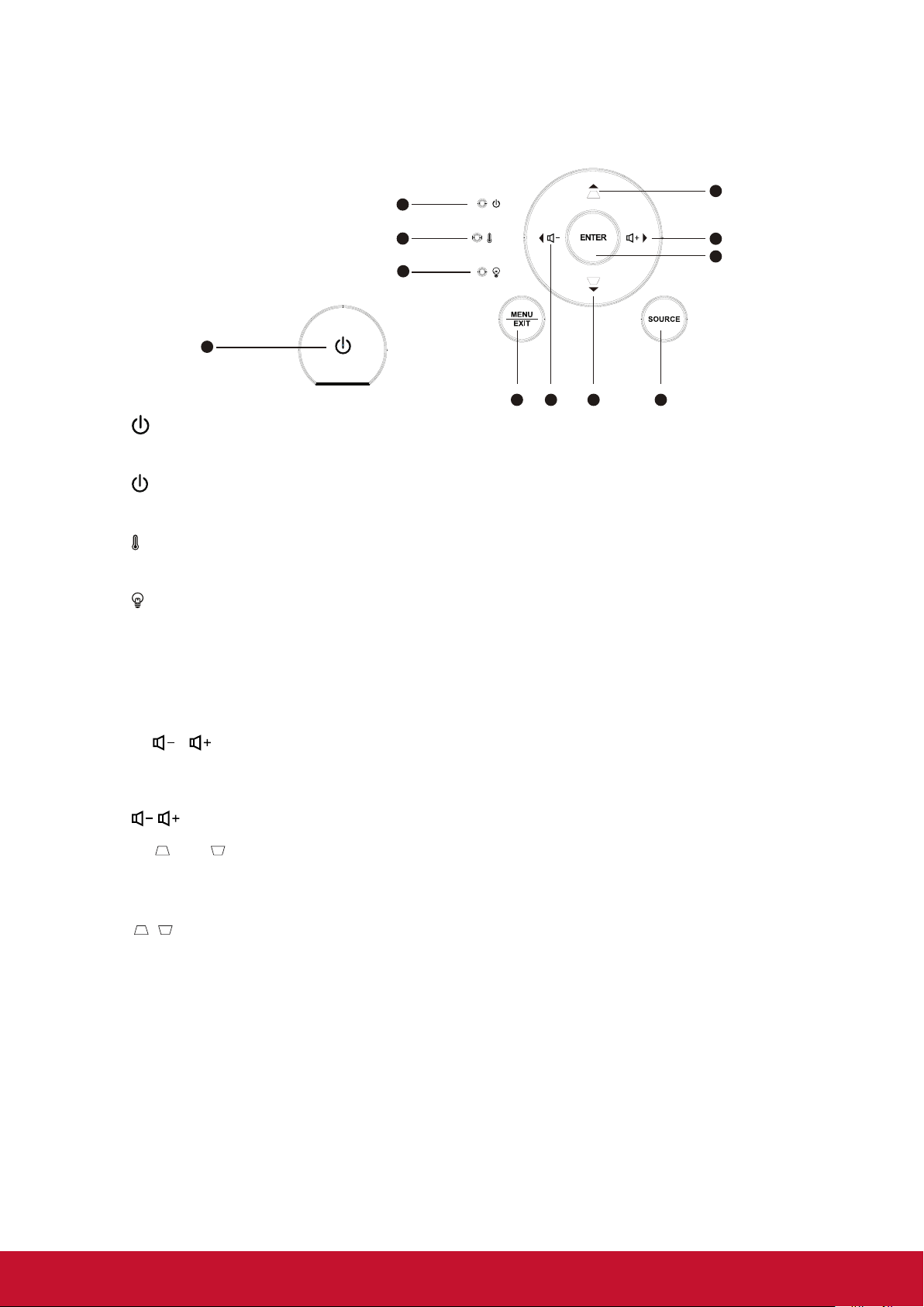
Device control and functions
6
75 8
⊳
⊳
Projector
1
1.
Turn the projector power on or off.
2.
3.
4.
(Power LED indicator)
Please refer to
“LED Indicator”.
(TEMP LED indicator)
Please refer to
“LED Indicator”.
(LAMP LED indicator)
Please refer to
“LED Indicator”.
2
3
4
7
6
9
5. Menu/Exit
Menu: Displays or exits the on-screen display menu.
Exit: Returns to the previous OSD menu, exits and saves the menu settings.
6.
/
Left/Right (direction buttons): Selects the required menu item to make
adjustments.
: Adjusts the projector’s sound level.
7.
/
Up/Down (direction buttons): Selects the required menu item to make
adjustments.
/ (Keystone button): Manually corrects distorted images resulting from an angled
projection.
8. Source
A source selection bar displays.
9. Enter
Enter the selected on-screen display (OSD) menu item.
6
Page 14

Remote control
10
1
12
13
16
18
20
21
22
23
24 25
27
29
30
31
1 2
3 4
5
6 7
8
1
9
15
14
17
19
26
28
1. On
Turn the projector on.
2.
Off
Turn the projector off.
3.
COMP
Select the D-Sub / component display.
4. HDMI 2
Select the source of the displayed
HDMI.
5. HDMI 1
Select the source of the displayed
HDMI.
6. Auto Sync
Automatically determine the optimum
image timing sequence for the images
to be displayed.
7. Source
A source selection bar displays.
8. 12.
Keystone button and direction
button
Manually corrects distorted images
resulting from an angled projection.
/
Up/Down
Selects the required menu item to
make adjustments.
9. 10.
Left/Right/
Displays the projector’s internal
information.
11. Enter
Enter the selected screen to display
(OSD) menu item.
13.
Setting
Open Menu.
14.
Exit
Return to the previous OSD menu to
exit and save the menu settings.
15.
Home
Back to home page.
16.
Pattern
Shows the inbuilt testing screens.
17. Blank
Hide screen image.
18.
Aspect
Selects the display aspect ratio.
19. HDR
Display HDR menu.
7
Page 15

20.
21.
22.
23.
24. Brightness
25. Color Temp
(Mute)
Toggles the projector audio between on
and off.
(Volume)
Decrease the volume.
(Volume+)
Increase the volume.
Contrast
Adjust contrast.
Adjust brightness.
Adjust color temperature.
26. Standard
Standard mode.
27. Sports
Sports mode.
28.
User 1
User mode 1.
29.
Movie
Movie mode.
30.
Eco Mode
Displays the Lamp Mode option list.
31.
User 2
User mode 2.
8
Page 16

Remote control effective range
There are infra-red (IR) remote control sensors located at the front and back of the
projector. Hold the remote control and maintain a perpendicular angle within 30 degrees
with the IR remote control sensor to achieve normal remote control functions. The distance
between the remote control and the sensor should not exceed 8 meters (about 26 feet).
Do not place any obstruction in front of the IR sensor on the projector as this may block
the IR beam.
Approx. 30°
1
2
Note
●
When an intense light source such as sunlight or uorescent light is used to illuminate the remote
sensor, the remote control may not work.
●
Operate the remote control where you can see the remote sensor.
●
Do not shake or drop the remote control.
●
Store the remote control in a cool, dry place.
●
Do not spill water on the remote control or place moist objects on it.
●
Do not disassemble the remote control.
9
Page 17

Replacing the remote control battery
1. To open the battery cover, place the remote control with the backside facing upwards.
Press down at the indicated area and then pull the battery lid upwards along the
indicated direction.
2. Take out the old batteries (if required) and then place 2 AAA batteries according to
the indicated orientation. The positive pole of the battery should be directed at the (+)
direction while the negative pole should be directed at the direction.
3. Align the battery cover with the bottom of the remote control and return the cover to
its original position to complete the process.
Open the battery cover as
shown in the illustration.
Install the battery as shown
in the illustration.
Cover the battery cover.
Warning
● Avoid keeping the remote control and battery in moist or hot places, such as the kitchen, bathroom, sauna,
solarium or car.
● Replace only with the same or equivalent type recommended by the battery manufacturer.
● Refer to the manufacturer’s instructions and local environmental regulations to dispose of old batteries.
● Do not throw batteries into res. There may be danger of an explosion.
● If the battery is at or if you will not be using the remote control for a while, remove the battery to prevent
battery leaks from damaging the remote control.
10
Page 18

Projector Positioning
Choosing a location
You may refer to the room layout or personal preference to determine the location of
installation. Considerations include size and position of the screen, location of a suitable
power outlet, as well as the location and distance between the projector and other
equipment.
There are 4 potential installation locations for the projector:
1. Front Table
For this location, the projector is placed right in front of the
screen. This is the most commonly employed means for
placing the projector. It is quick to setup and highly mobile.
After turning on the projector, go to Basic Settings >
Projector Projection menu and select Front Table.
2. Front Ceiling
For this location, the projector is suspended upside-down
from the ceiling in front of the screen.
Purchase a Projector Ceiling Mounting Kit from your dealer
to mount your projector on the ceiling.
After turning on the projector, go to Basic Settings >
Projector Projection menu and select Front Ceiling.
3. Rear Ceiling
For this location, the projector is suspended upside-down
from the ceiling behind the screen.
Note: A special rear projection screen and Projector Ceiling
Mounting Kit are required for this installation location.
After turning on the projector, go to Basic Settings >
Projector Projection menu and select Rear Ceiling.
4. Rear Table
For this location, the projector is placed right behind the
screen.
Note: A special rear projection screen is required.
After turning on the projector, go to Basic Settings >
Projector Projection menu and select Rear Table.
11
Page 19
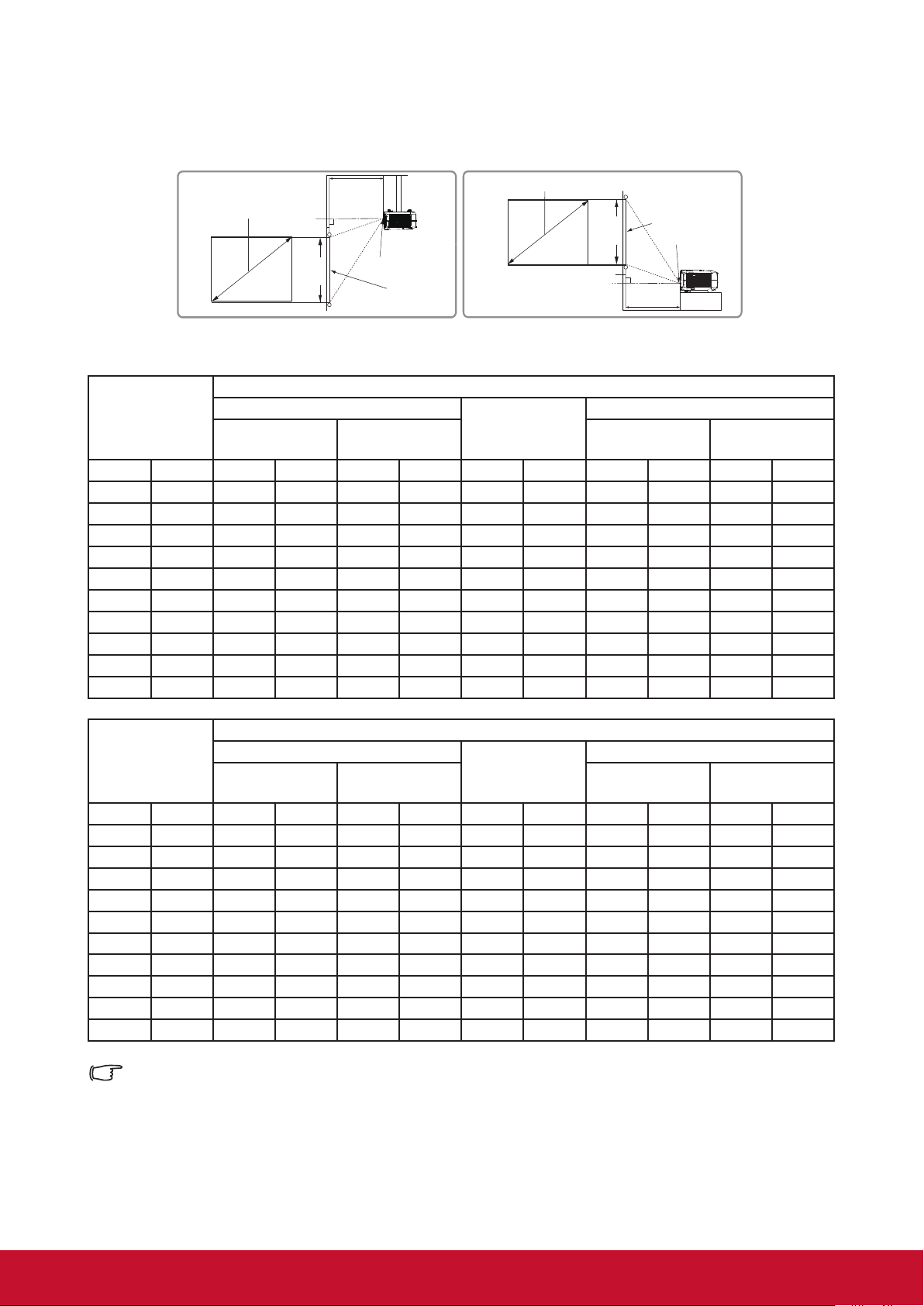
Projection Dimension
(a)
(c)
(b)
(e)
(f)
(d)
(a)
(c)
(b)
(e)
(f)
(d)
Refer to the chart below to determine the screen size and projection distance.
(E): Screen (f): lens center
Displays an image in 16:9 size on the 16:9 screen
(a) Screen size
(b) Projection distance
Minimum
distance
Maximum
distance
(c) Image height
Minimum offset Maximum offset
Inch mm Inch mm Inch mm Inch mm Inch mm Inch mm
60 1524 58 1483 77 1948 29 747 1.6 41 1.6 41
70 1778 68 1738 90 2281 34 872 1.9 48 1.9 48
80 2032 78 1993 103 2613 39 996 2.2 55 2.2 55
90 2286 88 2248 116 2945 44 1121 2.4 62 2.4 62
100 2540 99 2503 129 3278 49 1245 2.7 69 2.7 69
120 3048 119 3012 155 3942 59 1494 3.3 83 3.3 83
150 3810 149 3777 194 4939 74 1868 4.1 104 4.1 104
200 5080 199 5051 260 6601 98 2491 5.4 138 5.4 138
250 6350 249 6325 325 8262 123 3113 6.8 173 6.8 173
300 7620 299 7599 391 9924 147 3736 8.2 207 8.2 207
(d) Vertical offset
Displays an image in 4:3 size on the 16:9 screen
(a) Screen size
(b) Projection distance
Minimum
distance
Maximum
distance
(c) Image height
Minimum offset Maximum offset
(d) Vertical offset
Inch mm Inch mm Inch mm Inch mm Inch mm Inch mm
60 1524 53 1358 70 1785 27 686 1.5 38 1.5 38
70 1778 63 1592 82 2090 31 800 1.7 44 1.7 44
80 2032 72 1826 94 2395 36 914 2.0 51 2.0 51
90 2286 81 2059 106 2699 40 1029 2.2 57 2.2 57
100 2540 90 2293 118 3004 45 1143 2.5 63 2.5 63
120 3048 109 2761 142 3615 54 1372 3.0 76 3.0 76
150 3810 136 3463 178 4530 67 1714 3.7 95 3.7 95
200 5080 182 4632 238 6055 90 2286 5.0 127 5.0 127
250 6350 228 5801 298 7580 113 2858 6.2 159 6.2 159
300 7620 274 6971 358 9105 135 3429 7.5 190 7.5 190
There is 3% tolerance among these numbers due to optical component variations. It is
recommended that if you intend to permanently install the projector, you should physically test
the projection size and distance using the actual projector before you permanently install it, so
as to make allowance for this projector’s optical characteristics. This will help you determine
the exact mounting position so that it best suits your installation location.
12
Page 20

Connection
When connecting a signal source to the projector, be sure to:
1. Turn all devices off before making any connections.
2. Use the correct signal cables for each source.
3. Ensure the cables are rmly inserted.
In the connections shown below, some cables may not be included within the projector
packaging (please refer to “Shipping contents”).
You may purchase the required signal cables from an electronics store.
The following links and icons are for references only. Connection jacks at the back of the
projectors may differ according to the projector model.
Computer
USB
1
2
RS232
3
AV device
HDMI
4
5
6
7
LAN interface
USB charger
Internet
1. USB cable (mini-B to type A)
2. VGA cable (D-Sub to D-Sub)
3. RS-232 cable
4. HDMI cable
2
Monitor
Speaker
5. Composite video line
6. Audio Cable
7. RJ45 cable
13
6
Page 21

Connect to the computer or monitor
Connect to the computer
1. Use the VGA cable provided. Plug one end into the D-Sub output jack at the
computer end.
2. Connect the other end of the VGA cable to the COMPUTER signal input jack on
the projector.
Many notebooks have not activated their monitor jack after being connected to the monitor. The
user can often press FN + F3 or CRT/LCD button to switch ON/OFF the externally connected
monitor. Find the function key labeled with the CRT/LCD or monitor icon on the notebook. Press
the FN key and the labeled function key. Please refer to the instruction manual provided with the
notebook computer for the combination keys and their functions.
Connect to the monitor
If you want the display to be shown both on the computer monitor as well as the screen,
refer to the following instructions. Connect the VGA cable to the COMPUTER OUT signal
output jack on the projector as well as the external display.
1. Connect the projector to the computer as described in the “Connect to the computer”
section. Use a suitable VGA cable (only 1 such cable is provided) and connect one
end of the cable to the D-Sub input jack on the video display.
2. If the display is provided with a DVI input jack, then connect the DVI end of the VGADVI-A cable to the DVI input jack on the video display.
3. Connect the other end of the cable to the COMPUTER OUT jack on the projector.
The MONITOR OUT output is only available when the COMPUTER 1 is connected to the
projector in the standby mode. To use this connection mode, open the Power Management >
Active VGA Out function in the Standby Settings menu.
14
Page 22

Connecting to Video source devices
You can connect the projector to any of the following video source device with an output
jack:
• HDMI
• Video (composite video)
Only one of the aforementioned connection methods is required to connect the projector to
the video source device. However, different connection methods would provide a different
video quality. The connection method selected would be determined by the presence of
matching jacks on the projector and Video source device:
Best video quality
HDMI is the best video connection method available. If the source device comes with
HDMI jacks, you will be able to acquire uncompressed digital video quality.
Please refer to
HDMI devices.
If you don’t have any usable HDMI source, the next best video signal would be Component
Video (not to be confused with Composite Video). Digital TV tuners and DVD players are
provided with Component Video output sockets. If your device includes Component Video,
then this would be your primary choice of connection to the (composite) video.
“Connecting to HDMI devices” for details on how to connect the projector to
Least video quality
Composite Video is an analog video and will result in a perfectly acceptable, but less than
optimal result from your projector, being the least video quality of the available methods
described here.
Please refer to
connect your projector to composite video devices.
“Connecting to composite video source devices” for details on how to
Connecting audio
You can use the speakers of the projector in the presentation or connect other individual
speakers to the audio output jack of the projector. Audio output is controlled by the volume
and mute setup of the projector.
15
Page 23

Connecting to HDMI devices
Use an HDMI cable to establish a connection between the projector and HDMI device.
1. Connect one end of the HDMI cable to the HDMI output jack on the video device.
2. Connect the other end of the cable to the HDMI signal input jack on the projector.
In the unlikely event that the projector is connected to a DVD player via the projector’s HDMI
input and the projected picture displays wrong colors, please change the color space to YUV.
See “Changing HDMI input settings” for details.
Connecting to composite video source devices
Examine your Video source device to determine if an unused composite output jack is
available:
• If so, you can continue with this procedure.
• If not, you will need to reassess which method to use to connect to the device.
1. Take a Video cable and connect one end to the composite Video output socket of the
Video source device.
2. Connect the other end of the video cable to the VIDEO socket on the projector.
If the selected video image is not displayed after the projector is turned on and the correct
video source has been selected, check that the Video source device is turned on and operating
correctly. You must also check that the signal cables have been connected correctly.
Audio playback with the projector
You can use the speaker of the projector in the presentation or connect other individual
speakers to the AUDIO OUT jack of the projector.
16
Page 24

Operation
Activate the projector
Plug the power cord into the projector and into a wall socket. Turn on the switch on the
wall socket (if available).
Press
If this is the rst time that you've switched on the projector, please refer to on-screen
instructions and select your OSD language and Projection mode.
Power to switch on the projector.
Switch on all connected equipment.
The projector will then begin a search of the input signals. The options indicating green
light dots are the signal sources currently available. If the projector fails to detect a valid
signal, the screen will display a [NO SIGNAL] message until an input signal is found.
You can also press the [Source] key or the shortcut key on the remote control to select the
desired input signals. Please refer to
If the input signal frequency / resolution is outside the operating range of the projector, the
blank screen will display the [Out of Range] message. Please change to an input signal which is
compatible with the projector's resolution or set the input signal to a lower setting. For more
details, please refer to the “Timing chart”.
“Switching input signal” for the details.
17
Page 25

Using the menus
This projector has an on-screen display (OSD) menu function that allows you to
change different settings.
The following OSD screenshot is for reference only. Actual OSD design may differ.
The following is an overview of the OSD menu.
Main menu icon
18
Page 26
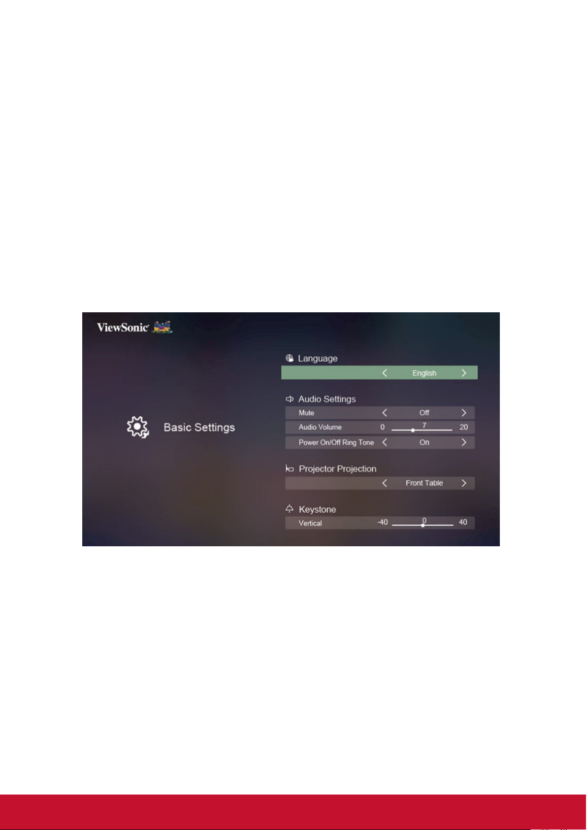
Use basic settings
When not connected to the signal source
1. Press the [Setting] key on the remote control and enter the menu. Then press the
/ key and select “Basic Settings” then press the [Enter] key.
2. Press the / key to select the function table.
3. Press the / key, and enter the sub-function table / adjust and set.
4. Press the [Exit] key and return to the previous function table or quit.
19
Page 27
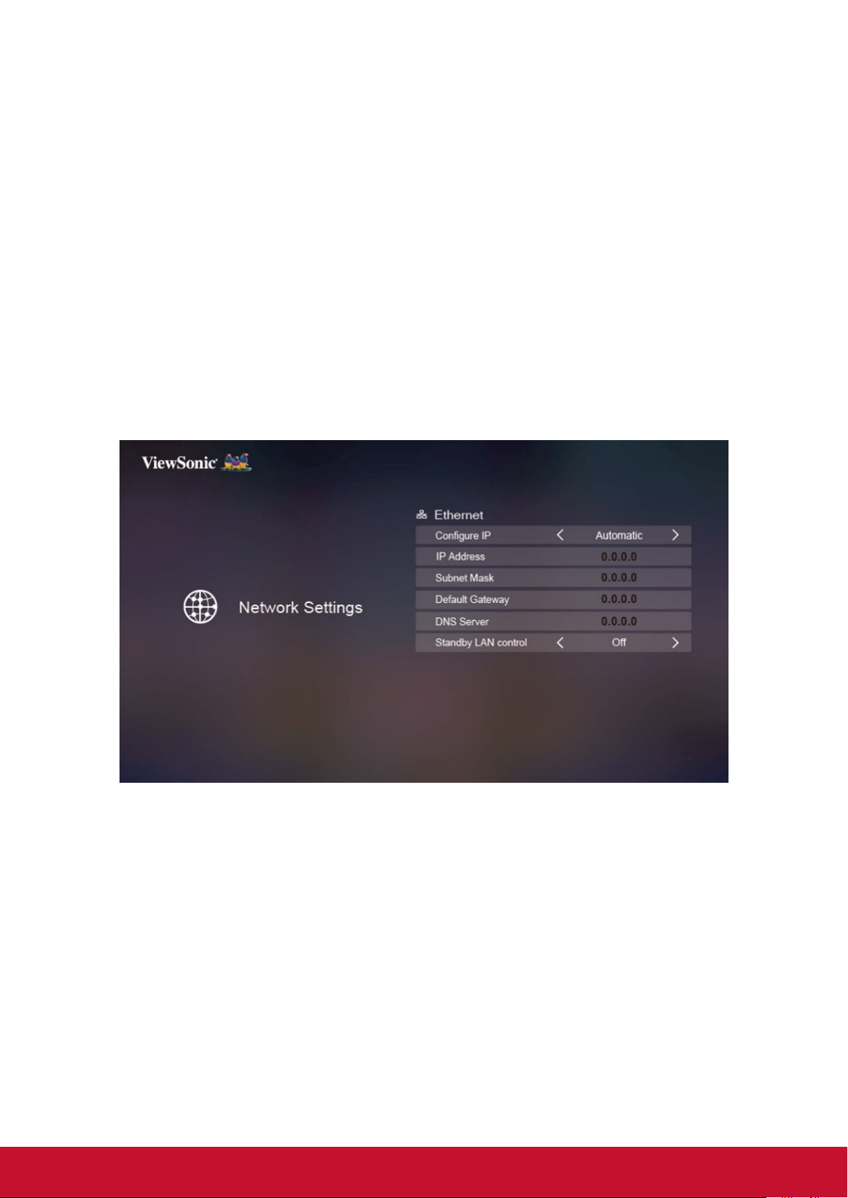
Use Network setting
When not connected to the signal source
5. Press the [Setting] key on the remote control and enter the menu. Then press the
/ key and select “Network Settings” then press the [Enter] key.
6. Press the / key to select the function table.
7. Press the / key, and enter the sub-function table / adjust and set.
8. Press the [Exit] key and return to the previous function table or quit.
20
Page 28

Use Advanced settings
When not connected to the signal source
1. Press the [Setting] key on the remote control and enter the menu. Then press the
/ key and select “Advanced Settings” then press the [Enter] key.
2. Press the / key to select the function table.
3. Press the / key, and enter the sub-function table / adjust and set.
4. Press the [Exit] key and return to the previous function table or quit.
21
Page 29
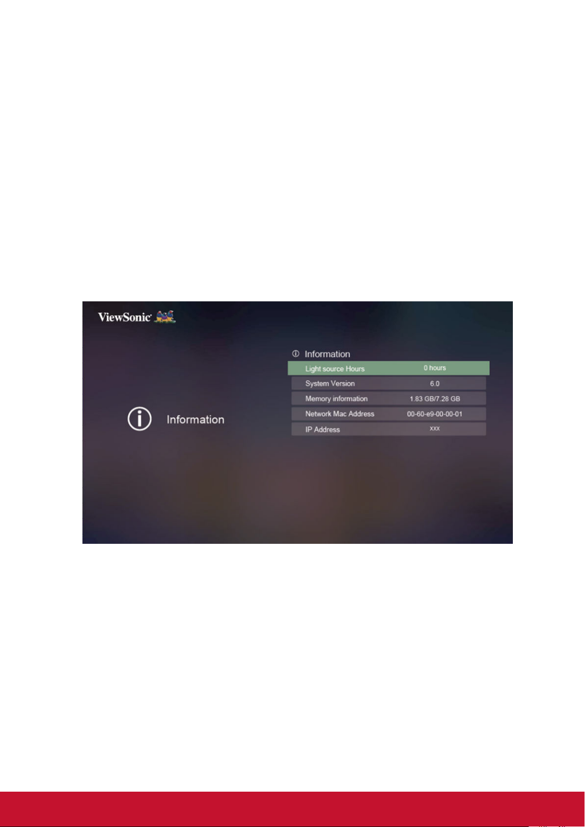
Use Information
When not connected to the signal source
1. Press the [Setting] key on the remote control and enter the menu. Then press the
/ key and select “Information” then press the [Enter] key.
2. Press the / key to select the function table.
3. Press the / key, and enter the sub-function table / adjust and set.
4. Press the [Exit] key and return to the previous function table or quit.
22
Page 30
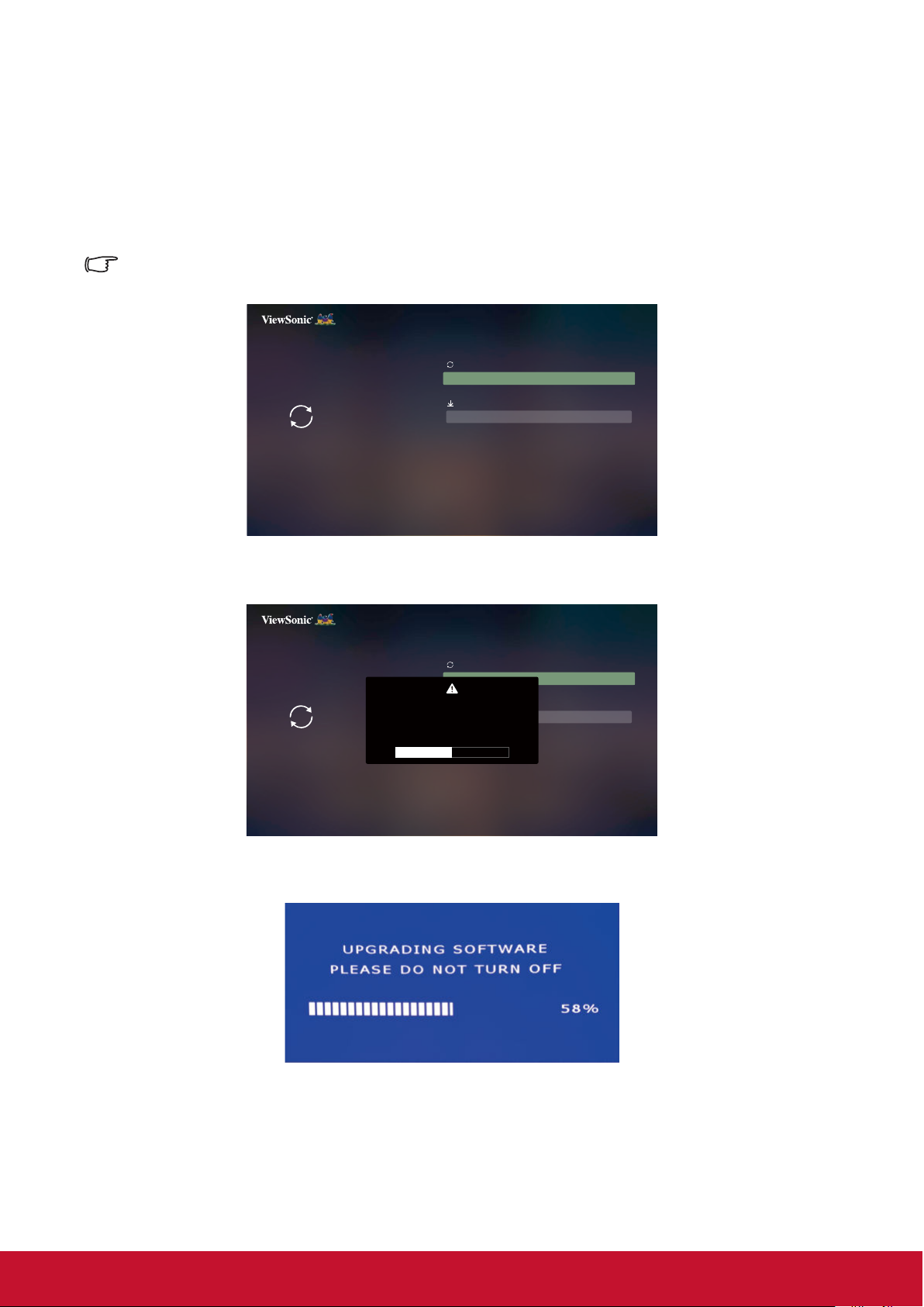
Use Firmware upgrade
Users can update the firmware by USB, and check the version.
1. Press [Setting] on the remote control and enter the menu. Then press /
and select “Software Upgrade ” then press [Enter].
The Firmware update process requires for downloading and copying BIN file to root directory of USB,
and then insert it into projector.
Software Upgrade
Software Update By USB
Version
Firmware Update
Firmware Version
0037
2.
Once Software Upgrade selected, then a warning message will be displayed on screen.
Software Upgrade
Software Update By USB
WARNING
Version
Firmware Update
Do you want to update the latest firmware?
Firmware Version
Yes Cancel
0037
3. After selecting Yes, update process is starting and a progress bar is indicated accordingly.
4. Projector will restart automatically once progress bar reaches 100%.
After projector restarted automatically, and language options appeared, then you need to
5.
manually restart projector again to complete the update procedure.
23
Page 31
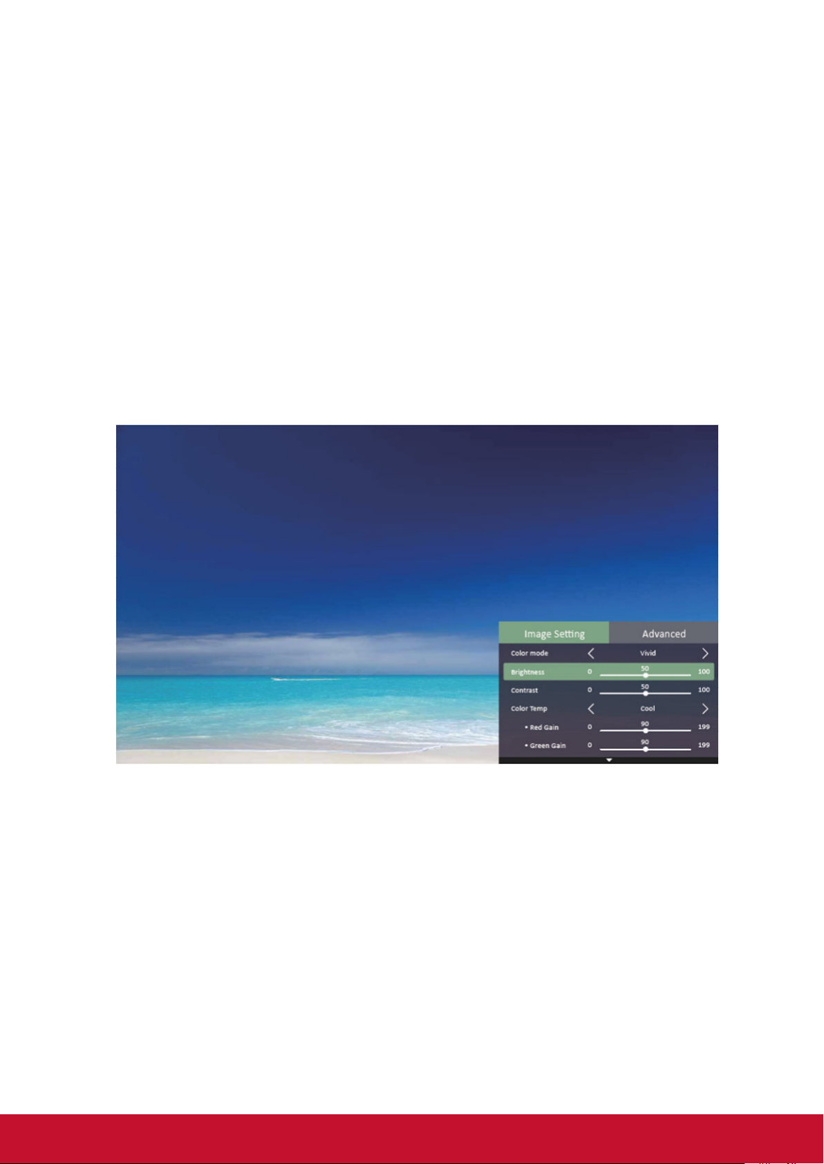
Use Image settings
When connected to the signal source
1. Press the [Setting] key on the remote control and enter the menu. Then press the
/ key and select “Image Setting” then press the [Enter] key.
2. Press the / key to select the function table.
3. Press the / key, and enter the sub-function table / adjust and set.
4. Press the [Exit] key and return to the previous function table or quit.
24
Page 32

Use Advanced settings (in signal source mode)
When connected to the signal source
1. Press the [Setting] key on the remote control and enter the menu. Then press the
/ key and select “Advanced” then press the [Enter] key.
2. Press the / key to select the function table.
3. Press the / key, and enter the sub-function table / adjust and set.
4. Press the [Exit] key and return to the previous function table or quit.
25
Page 33

Switching input signal
The projector can be connected to multiple devices at the same time. However, it can
only display one full screen at a time.
Please press the signal [Source] button on the remote control to search for the
available input signals. Then select the desired signal.
1. Press [Source] to display the source selection column.
2. Keep pressing the / until you arrive at the desired signal, then press [Enter].
Once the signal source is detected, the green dot near the available signal source
icon will light up.
For display resolutions of this projector, please refer to “Projector specications”.
To achieve the best image display effects, you should select and use an input signal that
outputs at this resolution. Any other resolutions will be scaled by the projector depending upon
the aspect ratio setting, which may cause some image distortion or loss of picture clarity. See
“Select the aspect ratio” for details.
26
Page 34

Changing HDMI input settings
In the unlikely event that you connect the projector to a device (such as DVD or
Bluray player) via the projector’s HDMI input jack, and the projected picture displays
the wrong colors, please change the color space settings to one that complies with
the color space settings of the output device.
To perform this operation:
1. After the signal source is connected, press the [Setting] key and enter the Advanced
> HDMI Setting menu.
2. Press [Enter].
3. Select Range, then press / to select a suitable color range according to the color
range settings of the output device.
● Full: Changes HDMI color range to 0-255.
● Limited: Changes HDMI color range to 16-235.
● Auto: Sets the projector to automatically detect the HDMI range of the input signal.
This function is only available when the HDMI input jack is being used.
Please refer to equipment documentation to gain more details on color space and HDMI range
settings.
27
Page 35

Adjusting the projected image
Adjusting the projection angle
The projector is furnished with an adjustment support
peg. The adjustment support peg may be used to
adjust projection height and projection angle along the
vertical axis. The user may turn the adjustment support
peg to make ne adjustments to projection angle and
position of the projected image until it reaches the
desired location.
If the projector is placed on an uneven surface or where the screen and projector
are not perpendicular to each other, the projected image may be subject to keystone
(trapezoidal) distortion. For more details on projection calibration, please refer to
“Perform keystone correction”.
Lift and adjust the feet
Auto-adjustments to the image
The focus ring can be used to adjust the image clarity.
Focus ring
Zoom ring
1. Turn the zoom ring to adjust the image size.
2. Sharpen the image by rotating the focus ring. It is recommended to use still images
for focusing.
28
Page 36

Perform keystone correction
Keystone distortion is a problem where the projected image becomes trapezoidal in shape
(keystone distortion) as a result of poor projection angle.
To correct this situation, you should adjust projector height and use the following steps to
correct the issue manually.
● Using the remote control
1. Press
2. Press
Keystone Correction at the bottom of the image.
● Using the OSD menu
Open the OSD menu and open Basic Settings > Keystone menu.
Adjust values: -40-40
/ to display the Keystone Correction page.
to initiate Keystone Correction at the top of the image. Press to initiate
29
Page 37

Using the CEC function
This projector supports the Consumer Electronics Control (CEC), allowing you to
connect to HDMI and achieve synchronized power ON/OFF operations. This means
that when a device that also supports CEC is connected to the HDMI input jack of the
projector, switching off the power of the projector will also automatically switch off the
power of the connected device. Switching on the power of the connected device will
also automatically switch on the projector.
Activating the CEC function:
1. Open the OSD menu and enter Advanced Settings > Auto Power On > CEC
menu.
2. Press / and select Enable.
To ensure proper operations of the CEC function, please verify that the target device has been
connected to the HDMI input jack via an HDMI cable and that the CEC function has been
activated.
CEC function may not be usable according to the connected equipment.
Smart energy-saving
Setting Auto Power Off
This function allows the projector to enter sleep mode automatically after the set time,
to avoid unnecessary wastage of the light source.
1. Open the OSD menu and enter the Advanced Settings > Smart Energy >
Auto Power Off menu, then press / Select time.
2. If the pre-set time length is not suitable for your needs, select Disable. The
projector will not automatically shut down in a certain time period.
Setting the Sleep Timer
This function allows the projector to enter sleep mode automatically after the set time,
to avoid unnecessary wastage of the life of the light source.
1. Open the OSD menu and enter the Advanced Settings > Smart Energy >
Sleep Timer menu, then press / Select time.
2. If the length of the pre-set time does not apply to your presentation, select
Disable. The projector will not automatically shut down in a certain time period.
Set power saving
If no input source is detected after 5 minutes. The projector will reduce power
consumption to avoid unnecessary wastage of the life of the light source. You can
further decide whether to let the projector turn off after the set time.
1. Open the OSD menu and enter the Advanced Settings > Smart Energy >
Power Saving menu, then press / Select Enable.
2. When Enable is selected, the light source of the projector will be changed
to Eco mode 5 minutes after no signal is detected. If the projector has not
detected the signal after 20 minutes, its light source power will be changed to
SuperEco mode.
30
Page 38

Light Source Mode
Light Source Mode
Sets the light Source Mode.
• Normal: 100% of the light source power
• Eco: 80% of the light source power
Light Source Hours
Display the duration that the light source has been running for (hours).
Operations at high altitudes
We recommend using the High Altitude Mode when the environment is at 1,500 to
3,000 meters above sea level and the temperature is between 5°C to 25°C.
Note
Do not activate High Altitude Mode if the environment is at 0 to 1,500 meters
above sea level and the temperature is between 5°C to 35°C.
Activating High Altitude Mode under such circumstances will lead to excessive
cooling of the projector.
Activating High Altitude Mode:
1. Open the OSD menu and enter Advanced Settings > High Altitude Mode menu.
2. The conrmation message will be shown, then press / to select Yes.
3. Press [Enter].
There is a chance that louder operational noises will be generated when using the
projector in High Altitude Mode. The reason for this is the increased fan speed
necessary to improve overall system cooling and performance.
Using this projector under extreme environments that exceed the aforementioned
limits may lead to auto-shutdown designed to prevent overheating of the projector.
Under such circumstances, you should switch to High Altitude Mode to solve these
issues. However, this does not mean that this projector is able to operate under any
and all harsh or extreme conditions.
Hiding the image
In order to draw the audience’s attention to the presenter, you may press [Blank]
to hide the screen image. Press any key on the projector or remote to restore the
image. After hiding the image, the lower right corner of the screen will display the text
[Blank].
Press the [Blank] key on the remote control, the projector will enter the power-saving mode
automatically.
Caution
Do not block the projector lens. The blocking item may be heated to the point of deformation or
may even cause a re.
31
Page 39

Optimize images in user mode
Selecting a picture mode
●The projector is preset with several predened picture modes. You may choose one of
these modes that best ts your operating environment and input signal picture type.
●To select an operation mode that suits your need, please follow the steps described
below.
●Press [Color Mode] repeatedly until you arrive at the mode you desire.
●Connect to the signal source, then press the [Setting] key to open the menu. Then
select Image Setting > Color Mode menu and press [Enter]. Then press / select
the desired mode.
Picture modes for different types of signals
The following lists the Picture modes that can be used for different signal types.
1. Standard mode: Suitable for normal conditions during the daytime.
2. Gaming: Tint suitable for gaming.
3. Movie Mode: Applicable for playing colored movies, video clips from digital cameras,
or DVs from a PC input in darker (dim) environments to achieve the best viewing
effects.
4. Brightest mode: Maximizes the brightness of the projected image. This mode is
suitable when using projectors in environments such as well-lit rooms where extrahigh brightness is required.
5. Sports mode: Tint suitable for watching sporting events.
6. User 1/User 2: Users can adjust the color according to their preferences.
Note: Switching to Movie mode will trigger the lter glass and bring about slight operating sounds.
32
Page 40

Fine-tuning of image quality in user modes
You may use several user-dened functions if the projector detects certain signal
types. You can make adjustments to these functions based on your needs.
Adjusting Brightness
Enter Image Setting > Brightness menu and then
press /.
The higher the value, the brighter the image. And
lower the setting, darker the image.
Adjusting this control allows the black area of the
image to appear just as black to reveal details within.
Adjusting Contrast
Enter Image Setting > Color Temp menu and then press /.
The higher the value, the greater the contrast. After
adjusting Contrast, this function may be used to
set the peak-white level that matches the input
signal and observed environment of your choice.
Selecting a Color Temperature
Enter Image Setting > Color Temp menu, and then press [Enter].
Options available to Color Temperature settings will depend on the choice of the
signal type.
1. 6500K: White colors in the image will be provided with a light red undertone.
2. 7500K: Maintains a normal white color tone.
3. 9300K: Provides the highest color temperature.
4. User: Customize.
Adjusting Tint
Enter Image Setting > Tint menu and press / and adjust the value.
The higher the value, the more reddish the picture becomes. The lower the value, the
more greenish the picture becomes.
This function is only available when the input signal is Video.
Adjust Saturation
Enter Image Setting > Saturation menu and press /.
The lower the set value, the smaller the color saturation. If the value is set too high,
the image color will be too strong which will produce an untrue image.
This function is only available when the input signal is video.
Adjusting Sharpness
Enter Image Setting > Sharpness menu and then press /.
Higher settings produce sharper images. The lower the value, the softer the picture
becomes.
This function is only available when the input signal is video.
33
Page 41

Adjust Gamma
Enter Image Setting > Gamma menu then press / and adjust the value.
1.8 / 2.0 / 2.2 / 2.35 / 2.5 / sRGB / Cubic, respectively, represent the different gray scale
curves.
This function is only available when the input signal is video.
Adjusting Brilliant Color
Enter Image Setting > Brilliant Color menu and press /.
This feature utilizes a new color-processing algorithm and system level
enhancements to enable higher brightness while providing truer, more vibrant
colors of the projected image. Brightness levels of mid-tone areas commonly
seen in videos and natural landscapes are increased by more than 50%,
allowing the projector to generate images in realistic and true colors. To acquire
this quality of images, please select the level you desire. If not required, set this
option to Off.
Red
Magenta
Yellow
Blue
Green
Cyan
Reducing image noise
Enter Image Setting > Noise Reduction menu, and then press /.
This function is capable of reducing image noise generated electrically by different media
players. Higher settings will provide lower image noise.
This function is only available when PC, Video input signals are selected.
34
Page 42

Color Management
Only in permanent installations with controlled lighting levels such as boardrooms, lecture
theaters, or home theaters, should color management be considered. Color management
provides ne color control adjustment to allow for more accurate color reproduction, should
you require it.
If you have purchased a test disc that contains various color test patterns that can be used
to test the color presentation of monitors, TVs, and projectors, any image from the disc can
be projected on screen and adjusted using the Color Management menu.
To adjust the settings:
1. After the signal source is connected, go to
Image Setting > Color Management menu.
2. Press [Enter] to bring up the Color Management
page.
3. Select Primary Color and press / to select any
one of the colors from red, yellow, green, cyan,
blue, or magenta.
4. Press to select the Tint, then press / to
select the range. Enlarging the range will include
colors composed of higher proportions of 2 similar
colors.
Please refer to the illustration to the right for how the colors relate to each other.
For example, if you select red and set the range to 0, you will only select pure red
areas of the projected image. Increasing the range will include shades of red closer
to yellow and magenta.
5. Press to select Saturation, then press / to adjust its values according to your
preferences. The effect of each adjustment will be immediately reected upon the
image.
For example, if you select Red and set its value at 0, only the saturation of pure red
will be affected.
Saturation is the amount of that color in a video picture. Lower settings produce less saturated
colors. A setting of 0 will remove that color from the image entirely. If the saturation is too high,
that color will be overpowering and unrealistic.
Red
Magenta
Yellow
Blue
Green
Cyan
6. Press and select Gain, then press / to adjust its values according to your
preferences. This affects the contrast level of the primary color selected. The effect of
each adjustment will be immediately reected upon the image.
7. Repeat steps 3 to 6 to carry out other color adjustments.
8. Make sure you have made all of the desired adjustments.
9. Press [Exit] to save the settings and exit.
35
Page 43

Fine-tuning of image in user modes
If the projector detects specic types of signals, you can use several customized
functions. You can adjust these functions as necessary.
Adjusting Digital zoom
Enter Image Setting > Digital Zoom menu and press / to adjust the value.
Adjust the option to zoom in or out the image.
Adjusting Position
Enter Image Setting > Position menu and press / to adjust the value.
Show Position adjustment page. Use the arrow keys when moving the projected
images. Each time the key is pressed, the value displayed in the bottom half of the
page will change accordingly, until the maximum or minimum.
This function is only available when the PC input signal is selected.
The adjustment range may vary at different time sequences.
Adjusting Phase
Enter Image Setting > Phase menu and press / to adjust the value.
Adjust the clock phase to reduce image morphing.
This function is only available when the PC input signal is selected.
Adjusting Horizontal size
Enter Image Setting > H. Size menu and press / to adjust the value.
Adjust the option to change the horizontal width of the image.
This function is only available when the PC input signal is selected.
Adjusting Overscan
Enter Image Setting > Overscan menu and press / to adjust the value.
To prevent an image from partially becoming deformed at the screen edges, the
overscan technology has been employed to enlarge the image by 5% or even 10%
and extend the deformed image beyond the screen to display only the middle part
with good linearity.
36
Page 44

Select the aspect ratio
The “Aspect Ratio” is the ratio of the image width against image height. It is 4:3 for most
analog TVs and computers, and 16:9 for digital TVs and DVDs. With the emergence of
digital signal processing, digital display equipment such as projectors can dynamically
stretch the images and display the outputted images with a ratio different from that of the
inputted image signals. Change projected image aspect ratio (for any signal source):
1. Connect to the signal source, then press the [Setting] key and enter the menu to
open the Advanced > Aspect Ratio menu.
2. Press / and select an aspect ratio matching the video signal format that meets
your display requirements.
About the aspect ratio
Choose how to make the screen suitable for the screen:
1. Auto: Proportional scaling of an image to t the
projector’s natural resolution in its horizontal
width. This is suitable where the incoming
image is neither in 4:3 nor 16:9 aspect ratios
but where you want to make most use of the
screen without altering the image’s aspect
ratio.
Image 16:10
Image 16:9
2. 4:3: Scales a picture so that it is displayed in the
center of the screen with a 4:3 aspect ratio.
This is most suitable for 4:3 pictures such
as those for computer monitors, standard
denition TV, and 4:3 aspect DVD movies
as these can be displayed without aspect
alteration.
3. 16:9: Scales a picture so that it is displayed in
the center of the screen with a 16:9 aspect
ratio. This is most suitable for images which
are already in a 16:9 aspect such as high
denition TV because as these can be
displayed without aspect alteration.
4. 16:10: Scales an image in ratio so that it is
displayed in the center of the screen with a
16:10 aspect ratio. This is most suitable for
images which are already in a 16:10 aspect
as it displays them with out aspect alteration.
5. Native: The image is projected as its original resolution, and resized to t within the
display area. For input signals with lower resolutions, the projected image
will display smaller than if resized to full screen.
Image 4:3
Image 16:9
Image 16:10
37
Page 45

3D functions
This projector also comes with 3D functions that offer greater depth and immersion
when viewing 3D movies, videos, sports, and games. You will need a pair of 3D
glasses when viewing 3D images and videos.
If the 3D signal comes from an HDMI 1.4a compatible device, this projector will look
for a 3D Sync data signal. Once detected, the projector will automatically switch to
3D projection. Under other circumstances, you may need to manually select the 3D
Sync format to ensure the proper projection of 3D images.
Selecting 3D Sync formats:
1. Connect the signal source and use the remote control or control panel to open the
menu. Select the Advanced > 3D Settings menu.
2. Press [Enter] to bring up the 3D Settings page.
Once 3D Sync function has been activated:
• Brightness of the projected image will be reduced.
• Color modes cannot be adjusted.
• Zoom functions can only enlarge the image to a limited degree.
If the 3D image has been severely inverted, you may set the 3D Sync Invert function to [Invert]
to correct this problem.
The 3D mode supports the following formats:
Timing Frame Sequential Top-Bottom Side-by-Side
1024x768@60Hz V V V
1280x720@60Hz V V V
1280 x 800 @ 60Hz V V V
1280 x 1024 @ 60Hz V V V
1366 x 768 @ 60Hz V V V
1440 x 900 @ 60Hz V V V
1600 x 1200 @ 60Hz V V V
1920 x 1080 @ 60Hz V V V
38
Page 46
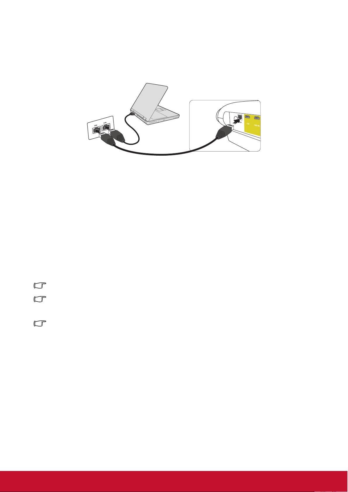
Control the projector through the local area network
This projector supports Crestron® software. After correct settings in the wired local area
network menu are nished, the projector can be managed on the computer with the
browser when the computer and the projector are correctly connected to the same local
area network.
(Example of connection)
Congure the wired local area network
If you are in a DHCP environment:
1. Connect one end of the RJ45 cable to the RJ45 local area network input jack of the
projector, and connect the other end to the RJ45 port.
2. Open the OSD menu and enter the Network Settings.
3. Select DHCP and then press / to select On.
4. Press to select the Apply and then press [Enter].
5. Please wait for about 15-20 seconds and then re-enter the page of the wired local
area network. The IP address, subnet mask, default gateway and DNS server
settings will be displayed. Please remember the IP address displayed in the IP
address.
If the IP address still does not display, contact the network administrator.
If the RJ45 cable is not correctly connected, the IP address, subnet mask, default gateway and
DNS server settings will be displayed as 0.0.0.0. Make sure the cable has been correctly
connected and re-execute the above steps.
To connect to the projector when the projector is in the standby mode, set the Network Settings
> Wired LAN > Standby LAN Control to On.
39
Page 47

If you are in a non-DHCP environment:
1. Repeat the above steps 1-2.
2. Select DHCP and then press / to select Off.
3. Contact your ITS administrator for the setting information about IP address, subnet
mask, default gateway and DNS server.
4. Press to select the item you want to modify and then press [Enter].
5. Press / to move the cursor and then press / to input the value.
6. To save the settings, press [Enter]. If you do not want to save the settings, press [Exit].
7. Press to select Apply and then press [Enter].
If the RJ45 cable is not correctly connected, the IP address, subnet mask, default gateway and
DNS server settings will be displayed as 0.0.0.0. Make sure the cable has been correctly
connected and re-execute the above steps.
To connect to the projector when the projector is in the standby mode, make sure the DHCP has
beens set to Off and the IP address, subnet mask, default gateway and DNS server information
have been acquired after the projector is powered on.
Control the projector with the web browser
If the correct IP address of the projector is acquired, and the projector is powered
on or in standby mode, any computer in the same local area network can be used to
control the projector.
If Microsoft Internet Explorer is used, make sure the version is 7.0 or higher.
The screenshots in this manual are for reference only. Actual OSD design may differ.
1. Enter the address of the projector in the address bar of your browser and press [Enter].
2. The homepage of “Network Control” is displayed.
3
4
5
Access to the Network Settings or Email Alert web page needs the administrator password. The
default password is “0000”.
40
Page 48

3. You can adjust AMX and SNMP settings on this page. On the AMX device discovery,
the controller connected to the AMX of the same network will nd the projector when
ON is selected. For details of the AMX Device Discovery, please access the AMX
website: http://www.amx.com/.
4. If the projector is connected to the network which supports the SMTP (Simple Mail
Transfer Protocol), you can congure it to send alarms via emails when important
events occur.
5. Crestron (e-Control) page displays the Crestron e-Control user interface. For details,
please refer to
“About Crestron e-Control®”.
41
Page 49

Please note the input length limits in the following table (including space and other
punctuation marks):
Type item Input length Maximum character
DHCP/Manual (None)
IP Address XXX.XXX.XXX.XXX
Network Settings
Email Alert
Network
Password
SNMP
Email Setting
SMTP Setting
Subnet Mask XXX.XXX.XXX.XXX
Gateway XXX.XXX.XXX.XXX
DNS Server XXX.XXX.XXX.XXX
AMX device discovery (None)
Administrator (None)
New Password 4
Conrm Password 4
SysLocation 22
SysName 22
SysContact 22
To 40
Cc 40
Subject 40
From 40
Server 30
User Name 21
Password 14
Alert Condition
/ > < $ % + \ ‘ “ are forbidden.
Fan Error (None)
Light source Error (None)
Over Temperature (None)
Light source Time Alert (None)
Submit (None)
Issue Test Mail (None)
42
Page 50

About Crestron e-Control
®
1. The Crestron e-Control® page provides various virtual buttons to control the projector
or adjust the projected image.
i
You can press
to display
/
ii
i
i
more buttons.
i. The functions of those buttons are identical with those on the OSD menu or
remote control.
ii. To switch the input signal source, please click the required signal.
The Menu button can be used to return to the previous OSD menu, exit and save menu settings.
The signal source list may differ from the available interfaces on the projector.
The web browser needs some time to perform change synchronization with the projector when
the projector control panel or remote control is used to change the OSD menu settings.
2. The Tools page can be used to manage the projector, congure the LAN control
settings, and perform remote network operation security access to the projector.
i iv
vi
ii
iii
v
i. This part can be used only in the case that the Crestron control system is used.
Please contact Creston or refer to its user guide to get a knowledge of the
installation information.
ii. You can name the projector, and record its position and responsible person.
43
Page 51

iii. You can adjust the wired local area network.
iv. After setup has nished, the remote network operation access to the projector is
protected with a password.
v. After setup has nished, access to the Tools page is protected with a password.
To avoid mistakes, please input the English letters and digits in the Tools page.
After adjustment, press the Send button and the data will be saved in the projector.
vi. Press [Exit] and then you can return to the remote network operation page.
Please note the input length limits in the following table (including space and other
punctuation marks):
Type item Input length Maximum character
Crestron Control IP Address 16
IP ID 4
Port 5
Projector Projector Name 32
Location 32
Assigned To 32
Network Conguration DHCP (Enabled) (None)
IP Address 16
Subnet Mask 16
Default Gateway 16
DNS Server 16
User Password Enabled (None)
New Password 26
Conrm 26
Admin Password Enabled (None)
New Password 26
Conrm 26
3. The Info page displays the information and status of this projector.
44
Press [Exit] and then you
can return to the remote
network operation page.
Page 52

4. Press “Contact IT Help” button, and then a HELP DESK window will be displayed in
the upper right corner of the screen. You can send information to the RoomView™
software administrator / user connected to the same local area network.
For details, please access http://www.crestron.com and http://www.crestron.com/
getroomview.
**Crestron RoomView
On the “Edit Room” page, input the IP address (or the host name) as the content
displayed in the screen display menu of the projector, and input “02” as the IPID, and
input “41794” as the reserved Crestron control port.
Regarding the Crestron RoomView™ settings and command method, please access
the following website to obtain the RoomView™ User Guide and more information:
http://www.crestron.com/products/roomview_connected_embedded_projectors_
devices/resources.asp
Support PJLink™, SNMP, AMX and Xpanel formats
This projector is compatible with PJLink™, SNMP V.1, AMX or Xpanel V1.10. For
details, please respectively refer to the User Guide or access the website to control
and manage the projector.
Using the projector under standby mode
A number of projector functions can be used under Standby Mode (plugged in to
power but not switched on). To use those functions, please conrm the cables and
wires have been correctly connected. Refer to the chapter on cable connections for
more information on cable connections.
LAN control
The setting in the Network Settings > Wired LAN > Standby LAN Control menu drives
the projector to provide network functions in the standby mode. For details, please
refer to
“Control the projector through the local area network”.
45
Page 53

Switch off the projector
1. Press the
message will disappear if you do not respond within a few seconds.
2. Press the
fan is completely stopped and unplug the power cord.
3. Disconnect the power cord from the wall socket if the projector will not be used for an
extended period of time.
Power button. A conrmation message will be displayed on screen. The
Power Button again, and the projector will be turned off. Wait until the
46
Page 54

Menu operations
Menu system (When not connected to signal source)
Please note that the on-screen display (OSD) menu may vary according to the type of
signal received.
The projector must detect at least one valid signal in order to use the menu items. If no
device has been connected to the projector or if no signal has been detected, only a few
menu items will be accessible.
Main menu Sub-menu Options
Language
Mute On/Off
1.
Basic Settings
Audio settings
Projector Projection
Keystone -40~40
Pattern Off/Test Card
Remote Control Code 1/2/3/4/5/6/7/8
Baud rate
Audio Volume 0~20
Power On/Off Ring Tone Off/On
Front Table / Front Ceiling/
Rear Table/ Rear Ceiling
115200/2400/4800/9600/14400/
19200/38400/57600
2.
Network
Settings
3.
Advanced
Settings
Congure IP
IP Address 0.0.0.0
Wired LAN
Power On Source
Auto Power On
Smart Energy
Light Source Mode Normal 100% / Eco 80%
High Altitude Mode
Reset All Settings Yes/Cancel
Subnet Mask 0.0.0.0
Default Gateway 0.0.0.0
DNS Server 0.0.0.0
Standby LAN Control Off/On
Direct Power On Disable/Enable
Signal Disable/VGA1/HDMI1/All
CEC Disable/Enable
Auto Power Off
Sleep Timer
Power Saving Disable/Enable
Off
On Yes/Cancel
Auto / Manual
Home/HDMI1/HDMI2/VGA1/
VGA2
10 min/ 20 min/ 30 min/
Disable
30 min/ 1 hr/ 2 hr/ 3 hr/ 4 hr/
8 hr/ 12 hr/Disable
47
Page 55

Main menu Sub-menu Options
· Light Source Hours
4.
Information
5.
· System Version
· Memory Information
· Network Mac Address
· IP Address
Software upgrade Software Update By USB
Firmware
Update
· FW Version · Firmware Version
48
Page 56

Menu system (When connected to signal source)
6.
Image Setting
7.
Advanced
Color Mode
Brightness 0~100
Contrast -50~50
Color Temp
Tint -99~99
Saturation 0~199
Sharpness 0~31
Gamma
Brilliant Color 1/2/3/4/5/6/7/8/9/10/Off
Noise Reduction Off / Low / Mid / High / Auto
Color Management
Digital Zoom 0.8x~2.0x
Position
Phase 0~100
H. Size -15~15
Overscan Off/1/2/3/4/5
Reset Current Color Settings Reset/Cancel
Aspect Ratio 16:9/16:10/Native/Auto
HDR Auto/SDR
EOTF Low / Mid / High
Frame Interpolation Off / Low / Mid / High
HDMI Setting Range Limited / Auto / Full
3D Settings
7500K/9300K/User/
6500K
·Primary Color R/G/B/C/M/Y
·Hue -99~99
·Saturation 0~199
·Gain 5~195
3D Format
3D Sync Invert Invert / Disable
Save 3D Settings
·Source
Movie/Sports/Gaming/User 1/
User 2/Brightest/Standard
·Red gain 0~199
·Green gain 0~199
·Blue gain 0~199
1.8/2.0/2.2/2.35/2.5/
sRGB/Cubic
X -5~5
Y -5~5
Off / Frame Sequential /
Frame Paking / Top-Bottom /
Side-by-Side / Auto
Information
·Resolution
·3D Format
·HDR
49
Page 57
Description of menu
Functions Description
Language
1. Basic Settings
2. Network Settings
Audio settings
Projector Projection Please refer to “Choosing a location” for the details.
Keystone
Pattern
Remote Control Code Please refer to the
Baud rate
Set language of the display screen (OSD) menu.
Please refer to
Mute
Audio Volume
Power On/Off Ring Tone
The will be a tone prompt when the projector is
powered on or off.
Please refer to
details.
The projector can display a test pattern. It can help you
adjust the image size and focal length to ensure that
there is no distortion of the projected images.
Please refer to the
details.
“Activate the projector” for the details.
“Perform keystone correction” for the
“IR control table” for the details.
“RS232 command table” for the
Network Settings Please refer to the “Network Settings” for the details.
Power On Source
3. Advanced Settings
Auto Power On
Please refer to the
details.
Signal
Set whether or not the projector will automatically adjust
when it is in standby mode and detects VGA or HDMI
signals of 5V power supply.
CEC
Please refer to “Using the CEC function” for the details.
Direct Power On
Once the power is supplied via power cord, the
projector can turn on automatically if “Enable” has
been selected.
“Switching input signal” for the
50
Page 58
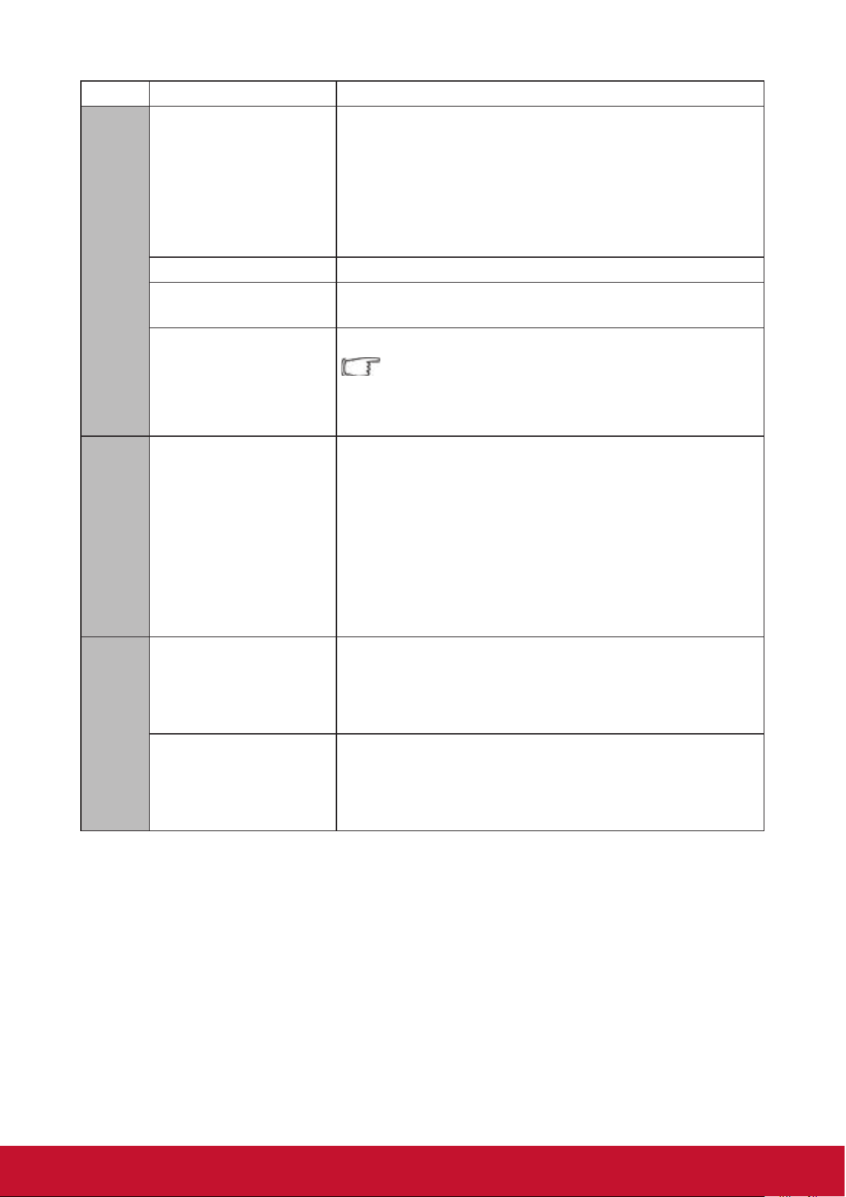
Functions Description
Auto Power Off
3. Advanced Settings
Smart Energy
Light Source Mode Please refer to the
High Altitude Mode
Reset All Settings
4. Information
Information
Please refer to
“Setting Auto Power Off” for the details.
Sleep Timer
Please refer to
“Setting the Sleep Timer” for the details.
Power Saving
Please refer to
“Set power saving” for the details.
“Light Source Mode” for the details.
Suitable to operate at high altitudes. Please refer to
“Operations at high altitudes” for the details.
Restore all the settings to the factory defaults.
The following settings will be preserved:
Keystone / Language / Projector Projection /
High Altitude Mode / Remote Control Code /
3D Settings / Network Settings
Light Source Hours
Display the light source hours
System Version
Display the system version
Memory Information
5. Firmware Update
Software upgrade Update the software By USB
Version Firmware Version
Display the memory information
IP Address
Display the network Mac address
51
Page 59

Functions Description
Color Mode
Brightness Please refer to
Contrast Please refer to “Adjusting Contrast” for the details.
Color Temp
Tint Please refer to
6. Image Setting
Saturation Please refer to
Sharpness Please refer to
Gamma Please refer to
Brilliant Color Please refer to “Adjusting Brilliant Color” for the details.
Noise Reduction Please refer to
Color Management Please refer to
Digital Zoom Please refer to “Adjusting Digital zoom” for the details.
Position Please refer to
Phase Please refer to
H. Size
Please refer to
“Selecting a picture mode” for the
details.
“Adjusting Brightness” for the details.
Please refer to
“Selecting a Color Temperature” for the
details.
“Adjusting Tint” for the details.
“Adjust Saturation” for the details.
“Adjusting Sharpness” for the details.
“Adjust Gamma” for the details.
“Reducing image noise” for the details.
“Color Management” for the details.
“Adjusting Position” for the details.
“Adjusting Phase” for the details.
Please refer to the
details.
“Adjusting Horizontal size” for the
Overscan Please refer to
Reset Current Color
Settings
Aspect Ratio Please refer to “Select the aspect ratio” for the details.
HDR
7. Advanced
EOTF
Frame Interpolation
HDMI Setting
“Adjusting Overscan” for the details.
Restore all the color settings to the factory defaults.
The projector supports HDR imaging. The dynamic
ranges of the signal sources for the HDMI1 and HDMI2
ports can be automatically detected, and the settings
can be optimized to display the contents with various
light source conditions.
The image brightness levels can be automatically
adjusted according to the input source. The manual
selection option is also available to adjust the
brightness level and show an image of better quality.
The function is not available when SDR is selected
in the HDR menu.
Smooth image quality of an object moving at high
speed. Especially suitable for users who like fast-paced
sport events.
Please refer to
“Changing HDMI input settings” for the
details.
3D Settings Please refer to the
Source
Resolution
Information
3D Format
HDR
52
“3D functions” for the details.
Page 60

Maintenance
Care of the projector
Do not attempt to disassemble any part of the projector. Contact your dealer if you
need to replace any parts.
Cleaning the lens
You can clean the dust-free glass lens if you notice any dirt or dust on its surface.
●Use a canister of compressed air to remove dust.
●Use a lens cleaning wipe, or a moist cloth with some detergent to clean away any dust
or dirt on the dust-free glass.
Note
Do not apply any granule material on the dust-free glass.
Cleaning the projector case
Before cleaning the case, please refer to the proper shutdown procedure described in
“Switch off the projector” to shutdown the projector and unplug the power cable.
●To remove dirt or dust, wipe the case with a soft, lint-free cloth.
●To remove stubborn dirt or stains, moisten a piece of soft cloth with water and a
neutral pH detergent. Then wipe the case.
Note
Never use wax, alcohol, benzene, thinners, or other chemical-based detergents. These can
damage the case.
Storing the projector
Follow the instructions below to store the projector for an extended time:
●Make sure the temperature and humidity of the storage area are within the
recommended range for the projector. Please refer to
dealer for details of the recommended range.
●Retract the projector support pegs.
●Remove the battery from the remote control.
●Pack the projector in its original packaging or equivalent material.
“Specications” or inquire your
Transporting the projector
It is recommended that you ship the projector within its original packaging or
equivalent material.
53
Page 61

LED Indicator
Projector status Power indicator Temp indicator Lamp indicator
Stand-by mode Green Flashing Off Off
Normally on Green Off Off
Normal Operations Green Off Off
Temperature Error
1
Temperature Error
2
Fan Error 1 Green Red Flashing Green
Fan Error 2 Green Red Flashing Green Flashing
Fan Error 3 or 4 Green Red Flashing Orange Flashing
Color Wheel Error Green Off Orange
Light bulb
abnormal
Heat dissipation
state
Green Red Flashing Orange
Green Red Flashing Off
Green Off Red
Green Green Flashing Off
54
Page 62
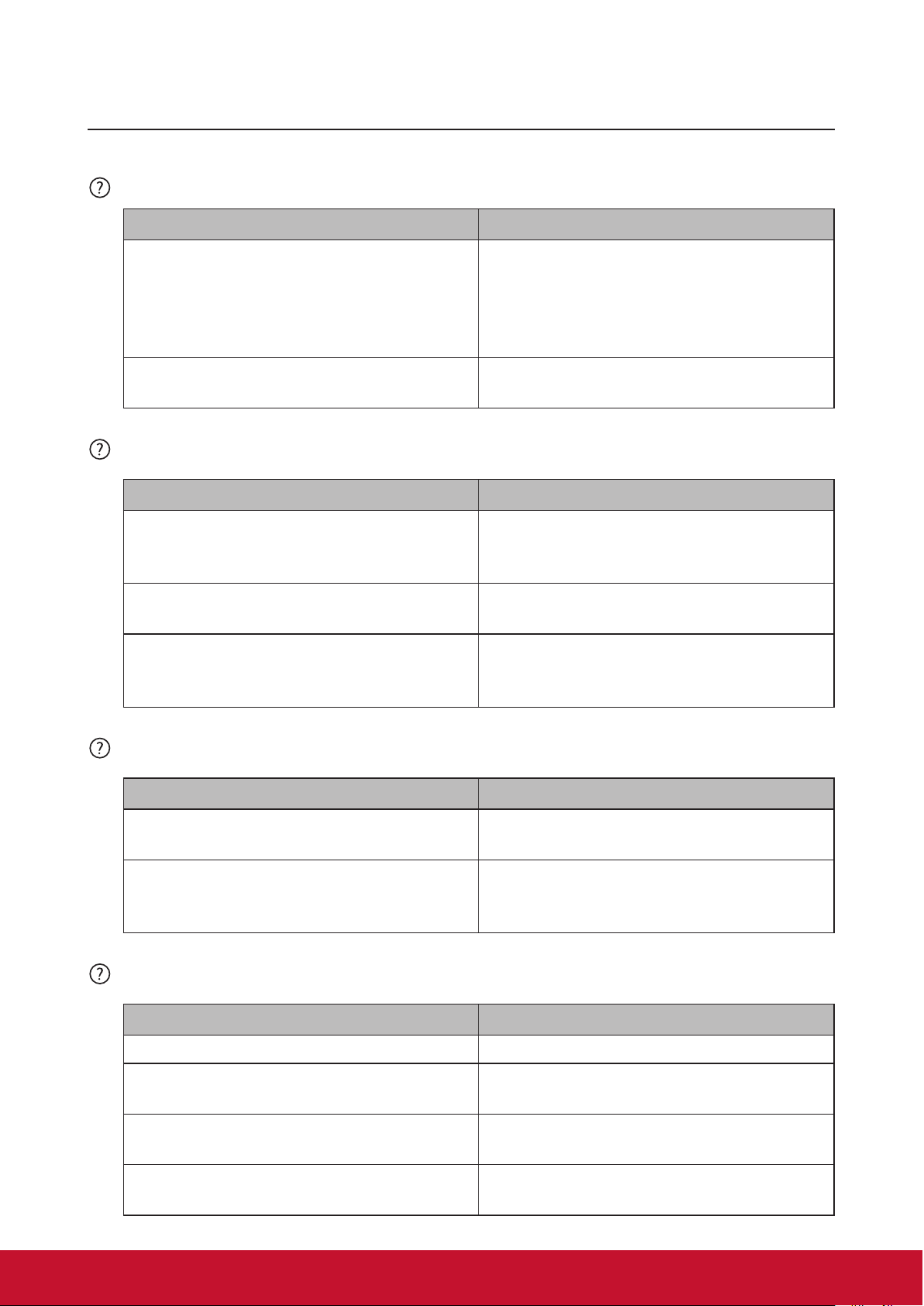
Troubleshooting
Projector is not shutting down
Cause Remedy
There is no power from the power cable.
Plug one end of the power cable at the
AC inlet of the projector and the other
end in the power outlet. If the power
outlet has a switch, make sure that it is
switched on.
Attempting to turn the projector on again
during the cooling process.
No picture
Cause Remedy
Video source is not turned on or is not
connected correctly.
The projector is not correctly connected
to the input signal device.
The input signal has not been correctly
selected.
Blurred image
Cause Remedy
Wait until the cooling down process has
completed.
Switch the video source on and check
that the signal cable is connected
correctly.
Check the connection.
Select the correct input signal by using
the [Source] key on the projector or
remote control.
The projection lens is not correctly
focused.
The projector and the screen are not
aligned properly.
Use the focus function to adjust lens
focus.
Adjust projection angle and direction as
well as the height of the projector where
necessary.
Remote control does not work
Cause Remedy
The battery is out of power. Replace the batteries.
There is an obstacle between the remote
control and the projector.
You are too far away from the projector.
The remote control does not match the
remote control code of the projector.
Remove the obstacle.
Stand within 8 meters (26 feet) of the
projector.
Adjust the remote control code.
55
Page 63
Specications
Projector specications
● All specications are subject to change without notice.
● Not all projector models are available at your location.
Input Terminals
1 VGA input (DB 15 pin) x2
2 HDMI (v1.4 with audio) x2
3 Video (RCA) x1
4 Audio input (3.5mm mini jack) x1
Output Terminals
1 Audio output (3.5mm mini jack) x1
2 USB-A 5V/1.5A x1
3 Speaker x1
4 VGA output x1
Control Terminals
1 RS232 (9 pin 1 type) x1
2 USB cable (mini B type) x1
3 LAN x1
Fuse specications
The fuse number used on the power PCB board is: F1, and the specifications are: 250V,
T6.3AH
56
Page 64

Dimensions
396.0mm
313.8mm
265.0mm
34.0mm
30.0mm
156.8mm
Ceiling mount installation
135.0mm
15.0mm
Note: It is recommended to use the M4L8 screw for xing the projector using the M4 screw
hole. (M4/ L8 x 4)
57
Page 65

Timing chart
Signal Resolution (pixels) Aspect Ratio Refresh rate (Hz)
VGA 640x480 4:3 60
SVGA 800x600 4:3 60
XGA 1024x768 4:3 60
WXGA 1280x800 16:10 60
Quad-VGA 1280x960 4:3 60
SXGA 1280x1024 5:4 60
SXGA+ 1400x1050 4:3 60
WXGA+ 1440x900 16:10 60
Analog RGB
UXGA 1600x1200 4:3 60
HDTV (1080p) 1920x1080 16:9 60
58
Page 66

HDMI
Signal Resolution (pixels) Aspect Ratio Refresh rate (Hz)
VGA 640x480 4:3 60
SVGA 800x600 4:3 60
XGA 1024x768 4:3 60
1280x768 15:9 60
1280x800 16:10 60
WXGA
1360x768 16:9 60
1366x768 16:9 60
Quad-VGA 1280x960 4:3 60
SXGA 1280x1024 5:4 60
SXGA+ 1400x1050 4:3 60
WXGA+ 1440x900 16:10 60
WSXGA+ 1680x1050 16:10 60
4K 3840x2160 16:9 24/25/30/50/60
HDTV (1080p) 1920x1080 16:9 50/60
HDTV (1080i) 1920x1080 16:9 50/60
HDTV (720p) 1280x720 16:9 50/60
SDTV(480p) 720x480 4:3/16:9 60
SDTV(576p) 720x576 4:3/16:9 50
SDTV (480i) 720x480 4:3/16:9 60
SDTV (576i) 720x576 4:3/16:9 50
59
Page 67

3D (including HDMI signal)
Signal Resolution (pixels) Aspect Ratio Refresh rate (Hz)
SVGA 800x600 4:3 60*/120
XGA 1024x768 4:3 60*/120
HD 1280x720 16:9 50*60*
WXGA 1280x800 16:9 60*
* 60 Hz signals are supported for side by side, Top and Bottom, and Frame Sequential
formats.
HDMI 3D
Within frame packing formats
Signal Resolution (pixels) Aspect Ratio Refresh rate (Hz)
1080p 1920x1080 16:9 23.98/24
720p 1280x720 16:9 50/59.94/60
Within side by side formats
Signal Resolution (pixels) Aspect Ratio Refresh rate (Hz)
1080i 1920x1080 16:9 50/59.94/60
720p 1280x720 16:9 50/60
Within Top and Bottom formats
Signal Resolution (pixels) Aspect Ratio Refresh rate (Hz)
1080p 1920x1080 16:9 23.98/24
720p 1280x720 16:9 50/59.94/60
60
Page 68

Composite video
Signal Aspect Ratio Refresh rate (Hz)
NTSC 4:3 60
PAL 4:3 50
PAL60 4:3 60
61
Page 69

Copyright information
Copyright
Copyright 2019. All rights reserved. No part of this publication may be reproduced, transmitted, transcribed,
stored in a retrieval system or translated into any language or computer language, in any form or by any
means, electronic, mechanical, magnetic, optical, chemical, manual or otherwise, without the prior written
permission of ViewSonic.
Disclaimer
ViewSonic does not make any statement or warranty, expressed or implied, for the merchantability and
tness for a particular purpose with respect to any contents within this manual. Additionally, ViewSonic
reserves the right to revise and update the contents of this manual without notice.
*DLP and Digital Micromirror Device (DMD) are trademarks of Texas Instruments. Other names would be the
copyrights of the respective companies or organizations.
62
Page 70

Appendix
IR control table
Key Format Byte 1 Byte 2 Byte 3 Byte 4
Power ON NEC-F1 X3 F4 4F BO
Power Off NEC-F1 X3 F4 4E B1
COMP NEC-F1 X3 F4 41 BE
HDMI 1 NEC-F1 X3 F4 58 A7
HDMI 2 NEC-F1 X3 F4 59 A6
Auto sync NEC-F1 X3 F4 8 F7
Source NEC-F1 X3 F4 40 BF
Up/keystone up NEC-F1 X3 F4 0B F4
Left NEC-F1 X3 F4 0E F1
Enter NEC-F1 X3 F4 15 EA
Right NEC-F1 X3 F4 0F F0
Down/keystone
down
Menu/Setting NEC-F1 X3 F4 30 CF
Home NEC-F1 X3 F4 16 E9
Exit NEC-F1 X3 F4 28 D7
Aspect NEC-F1 X3 F4 13 EC
Pattern NEC-F1 X3 F4 55 AA
Blank NEC-F1 X3 F4 07 F8
HDR NEC-F1 X3 F4 A0 5F
Mute NEC-F1 X3 F4 14 EB
Volume- NEC-F1 X3 F4 83 7C
Volume+ NEC-F1 X3 F4 82 7D
Brightness/ID Set NEC-F1 X3 F4 60 9F
Contrast/1 NEC-F1 X3 F4 61 9E
Color Temp./2 NEC-F1 X3 F4 66 99
Sports/3 NEC-F1 X3 F4 65 9A
Standard/4 NEC-F1 X3 F4 62 9D
User 1/5 NEC-F1 X3 F4 84 7B
Eco Mode/ 6 NEC-F1 X3 F4 2B D4
Movie/7 NEC-F1 X3 F4 64 9B
User 2/8 NEC-F1 X3 F4 85 7A
NEC-F1 X3 F4 0C F3
63
Page 71

Address Code
Code 1 83F4
Code 2 93F4
Code 3 A3F4
Code 4 B3F4
Code 5 C3F4
Code 6 D3F4
Code 7 E3F4
Code 8 F3F4
RS232 command table
<Pin assignment for this two end>
Pin Description Pin Description
1 NC 2 RX
3 TX 4 NC
5 GND 6 NC
7 RTSZ 8 CTSZ
9 NC
<Interface>
RS-232 protocol
Baud Rate 115200bps (default)
Data Length 8 bit
Parity check None
Stop bit 1 bit
flow control None
64
Page 72

<RS232 Command List>
1
Write
0x05 0x14 0x00 0x03 0x00 0x00 0x00 0x01
The below table list all RS232 commands frequently used:
No. Function Type Action Command Response The response of Query Read command
Power
2 Power Write
3 Power
Power Read Status
Write
ON
OFF
ON/
OFF
0x06 0x14 0x00 0x04 0x00 0x34 0x11
0x00 0x00 0x5D
0x06 0x14 0x00 0x04 0x00 0x34 0x11
0x01 0x00 0x5E
0x06 0x14 0x00 0x04 0x00 0x34 0x11
0x34 0x00 0x91
0x07 0x14 0x00 0x05 0x00 0x34 0x00
0x00 0x11 0x00 0x5E
0x03 0x14 0x00 0x00 0x00 0x14
0x03 0x14 0x00 0x00 0x00 0x14
0x03 0x14 0x00 0x00 0x00 0x14
0x05 0x14 0x00 0x03 0x00 0x00
0x00 0x01 0x18
0x18
0x05 0x14 0x00 0x03 0x00 0x00 0x00 0x00
0x17
54 Projector
Status
6 Reset All
Settings
Read Status
(Note 7)
Write Reset All
Settings
0x07 0x14 0x00 0x05 0x00 0x34 0x00
0x00 0x11 0x26 0x84
0x06 0x14 0x00 0x04 0x00 0x34 0x11
0x02 0x00 0x5F
Wa r m u p :0x 05 0 x 14 0 x00 0 x03 0x0 0 0x0 0 0x0 0 0x0 1 0x 18
Co ol dow n :0x 05 0 x1 4 0x00 0x03 0x0 0 0x00 0x 00 0x0 3 0x1 A
Po wer O n :0 x05 0 x1 4 0x00 0 x 03 0x 00 0 x 00 0 x 00 0 x 02 0x 19
Po wer D o w n : 0x0 5 0x14 0x00 0 x03 0x0 0 0 x 00 0 x 00 0 x 00 0 x 17
0x03 0x14 0x00 0x00 0x00 0x14
65
Page 73

No. Function Type Action Command Response The response of Query Read command
Write
Rear Table
0x06 0x14 0x00 0x04 0x00 0x34 0x12
0x03 0x14 0x00 0x00 0x00 0x14
0x05 0x14 0x00 0x03 0x00 0x00 0x00 0x01
3D Sync
Write
Frame
0x06 0x14 0x00 0x04 0x00 0x34 0x12
0x03 0x14 0x00 0x00 0x00 0x14
0x05 0x14 0x00 0x03 0x00 0x00 0x00 0x02
3D Sync
Write
Side by Side
0x06 0x14 0x00 0x04 0x00 0x34 0x12
0x03 0x14 0x00 0x00 0x00 0x14
0x05 0x14 0x00 0x03 0x00 0x00 0x00 0x05
3D Sync
Write
ON
0x06 0x14 0x00 0x04 0x00 0x34 0x12
0x03 0x14 0x00 0x00 0x00 0x14
0x05 0x14 0x00 0x03 0x00 0x00 0x00 0x01
Contrast
Write
Increase
0x06 0x14 0x00 0x04 0x00 0x34 0x12
0x03 0x14 0x00 0x00 0x00 0x14
Brightness
Write
Increase
0x06 0x14 0x00 0x04 0x00 0x34 0x12
0x03 0x14 0x00 0x00 0x00 0x14
Aspect ratio
Write
4:3
0x06 0x14 0x00 0x04 0x00 0x34 0x12
0x03 0x14 0x00 0x00 0x00 0x14
0x05 0x14 0x00 0x03 0x00 0x00 0x00 0x02
Projector
7
Position
8
3D Sync Write OFF 0x06 0x14 0x00 0x04 0x00 0x34 0x12
9
3D Sync Write Auto 0x06 0x14 0x00 0x04 0x00 0x34 0x12
10
11
3D Sync Write Frame Packing
12
3D Sync Write Top Bottom 0x06 0x14 0x00 0x04 0x00 0x34 0x12
13
14
3D Sync Read Status 0x07 0x14 0x00 0x05 0x00 0x34 0x00
15
3D Sync
nvert
16
nvert
17
3D Sync
nvert
18
Contrast Write Decrease 0x06 0x14 0x00 0x04 0x00 0x34 0x12
19
20
Contrast Read Get Value 0x07 0x14 0x00 0x05 0x00 0x34 0x00
I
21
Brightness Write Decrease 0x06 0x14 0x00 0x04 0x00 0x34 0x12
I
22
I
23
Brightness Read Get Value 0x07 0x14 0x00 0x05 0x00 0x34 0x00
24
Aspect ratio Write Auto 0x06 0x14 0x00 0x04 0x00 0x34 0x12
25
26
Aspect ratio Write 16:9 0x06 0x14 0x00 0x04 0x00 0x34 0x12
27
Aspect ratio Write 16:10 0x06 0x14 0x00 0x04 0x00 0x34 0x12
Aspect ratio Write Native 0x06 0x14 0x00 0x04 0x00 0x34 0x12
28
29
Aspect ratio Write Cycle 0x06 0x14 0x00 0x04 0x00 0x34 0x13
Aspect ratio Read Get Value 0x07 0x14 0x00 0x05 0x00 0x34 0x00
30
Auto Adjust Write Execute 0x06 0x14 0x00 0x04 0x00 0x34 0x12
31
32
Horizontal
position
Sequential
Write OFF 0x06 0x14 0x00 0x04 0x00 0x34 0x12
Read Status 0x07 0x14 0x00 0x05 0x00 0x34 0x00
Write Shift Right 0x06 0x14 0x00 0x04 0x00 0x34 0x12
0x00 0x01 0x5F
0x20 0x00 0x7E
0x20 0x01 0x7F
0x20 0x02 0x80
0x06 0x14 0x00 0x04 0x00 0x34 0x12
0x20 0x03 0x81
0x20 0x04 0x82
0x20 0x05 0x83
0x00 0x12 0x20 0x7F
0x21 0x00 0x7F
0x21 0x01 0x80
0x00 0x12 0x21 0x80
0x02 0x00 0x60
0x02 0x01 0x61
0x00 0x12 0x02 0x61
0x03 0x00 0x61
0x03 0x01 0x62
0x00 0x12 0x03 0x62
0x04 0x00 0x62
0x04 0x02 0x64
0x04 0x03 0x65
0x04 0x04 0x66
0x04 0x09 0x6B
0x31 0x00 0x90
0x00 0x12 0x04 0x63
0x05 0x00 0x63
0x06 0x01 0x65
0x18
0x03 0x14 0x00 0x00 0x00 0x14 0x05 0x14 0x00 0x03 0x00 0x00 0x00 0x00
0x03 0x14 0x00 0x00 0x00 0x14 0x05 0x14 0x00 0x03 0x00 0x00 0x00 0x01
0x03 0x14 0x00 0x00 0x00 0x14 0x05 0x14 0x00 0x03 0x00 0x00 0x00 0x03
0x03 0x14 0x00 0x00 0x00 0x14 0x05 0x14 0x00 0x03 0x00 0x00 0x00 0x04
0x05 0x14 0x00 0x03 0x00 0x00
0x00 0x00 0x17
0x03 0x14 0x00 0x00 0x00 0x14 0x05 0x14 0x00 0x03 0x00 0x00 0x00 0x00
0x05 0x14 0x00 0x03 0x00 0x00
0x00 0x00 0x17
0x03 0x14 0x00 0x00 0x00 0x14
0x05 0x14 0x00 0x04 0x00 0x00
0x00 0x00 0x00 0x18
0x03 0x14 0x00 0x00 0x00 0x14
0x05 0x14 0x00 0x04 0x00 0x00
0x00 0x32 0x00 0x4A
0x03 0x14 0x00 0x00 0x00 0x14 0x05 0x14 0x00 0x03 0x00 0x00 0x00 0x00
0x03 0x14 0x00 0x00 0x00 0x14 0x05 0x14 0x00 0x03 0x00 0x00 0x00 0x03
0x03 0x14 0x00 0x00 0x00 0x14 0x05 0x14 0x00 0x03 0x00 0x00 0x00 0x04
0x03 0x14 0x00 0x00 0x00 0x14 0x05 0x14 0x00 0x03 0x00 0x00 0x00 0x09
0x03 0x14 0x00 0x00 0x00 0x14
0x05 0x14 0x00 0x03 0x00 0x00
0x00 0x00 0x17
0x03 0x14 0x00 0x00 0x00 0x14 Note 6.
0x03 0x14 0x00 0x00 0x00 0x14
0x17
0x18
0x19
0x1A
0x1B
0x1C
0x17
0x18
Refer to value mapping table 3.2.2 (2 byte)
Refer to value mapping table 3.2.2 (2 byte)
0x17
0x19
0x1A
0x1B
0x20
66
Page 74

No. Function Type Action Command Response The response of Query Read command
Color mode
Read
Status
0x07 0x14 0x00 0x05 0x00 0x34 0x00
0x05 0x14 0x00 0x03 0x00 0x00
Primary
Write G 0x06 0x14 0x00 0x04 0x00 0x34 0x12
0x03 0x14 0x00 0x00 0x00 0x14
0x05 0x14 0x00 0x03 0x00 0x00 0x00 0x01
Primary
Write M 0x06 0x14 0x00 0x04 0x00 0x34 0x12
0x03 0x14 0x00 0x00 0x00 0x14
0x05 0x14 0x00 0x03 0x00 0x00 0x00 0x04
33
Horizontal
position
34
Horizontal
position
35
Vertical
position
36
Vertical
position
37
Vertical
position
38
Color
emperature
39
Color
emperature
40
Color
emperature
41
Color
emperature
42
Blank Write ON 0x06 0x14 0x00 0x04 0x00 0x34 0x12
43
Blank Write OFF 0x06 0x14 0x00 0x04 0x00 0x34 0x12
44
Blank Read Status 0x07 0x14 0x00 0x05 0x00 0x34 0x00
45
Keystone-V
ertical
46
Keystone-V
ertical
47
Keystone-V
ertical
48
Color mode Write Brightest 0x06 0x14 0x00 0x04 0x00 0x34 0x12
49
Color mode Write Movie 0x06 0x14 0x00 0x04 0x00 0x34 0x12
Color mode Write
50
51 Color mode Write
52
Color mode Write
Write Shift Left 0x06 0x14 0x00 0x04 0x00 0x34 0x12
Read Get Value 0x07 0x14 0x00 0x05 0x00 0x34 0x00
Write Shift Up 0x06 0x14 0x00 0x04 0x00 0x34 0x12
Write Shift Down 0x06 0x14 0x00 0x04 0x00 0x34 0x12
Read Get Value 0x07 0x14 0x00 0x05 0x00 0x34 0x00
Write Warm 0x06 0x14 0x00 0x04 0x00 0x34 0x12
Write Normal 0x06 0x14 0x00 0x04 0x00 0x34 0x12
Write Cool 0x06 0x14 0x00 0x04 0x00 0x34 0x12
Read Get Value 0x07 0x14 0x00 0x05 0x00 0x34 0x00
Write Decrease 0x06 0x14 0x00 0x04 0x00 0x34 0x12
Write Increase 0x06 0x14 0x00 0x04 0x00 0x34 0x12
Read Get value 0x07 0x14 0x00 0x05 0x00 0x34 0x00
Standard
User1
User2
0x06 0x00 0x64
0x00 0x12 0x06 0x65
0x07 0x00 0x65
0x07 0x01 0x66
0x00 0x12 0x07 0x66
0x08 0x00 0x66
0x08 0x01 0x67
0x08 0x03 0x69
0x00 0x12 0x08 0x67
0x09 0x01 0x68
0x09 0x00 0x67
0x00 0x12 0x09 0x68
0x0A 0x00 0x68
0x0A 0x01 0x69
0x00 0x12 0x0A 0x69
0x0B 0x00 0x69
0x0B 0x01 0x6A
0x06 0x14 0x00 0x04 0x00 0x34
0x12 0x0B 0x04 0x6D
0x06 0x14 0x00 0x04 0x00 0x34
0x12 0x0B 0x18 0x81
0x06 0x14 0x00 0x04 0x00 0x34 0x12
0x03 0x14 0x00 0x00 0x00 0x14
0x05 0x14 0x00 0x03 0x00 0x00
0x00 0x00 0x17
0x03 0x14 0x00 0x00 0x00 0x14
0x03 0x14 0x00 0x00 0x00 0x14
0x05 0x14 0x00 0x03 0x00 0x00
0x00 0x00 0x17
0x03 0x14 0x00 0x00 0x00 0x14 0x05 0x14 0x00 0x03 0x00 0x00 0x00 0x00
0x03 0x14 0x00 0x00 0x00 0x14 0x05 0x14 0x00 0x03 0x00 0x00 0x00 0x01
0x03 0x14 0x00 0x00 0x00 0x14 0x05 0x14 0x00 0x03 0x00 0x00 0x00 0x03
0x05 0x14 0x00 0x03 0x00 0x00
0x00 0x00 0x17
0x03 0x14 0x00 0x00 0x00 0x14 0x05 0x14 0x00 0x03 0x00 0x00 0x00 0x01
0x03 0x14 0x00 0x00 0x00 0x14 0x05 0x14 0x00 0x03 0x00 0x00 0x00 0x00
0x05 0x14 0x00 0x03 0x00 0x00
0x00 0x00 0x17
0x03 0x14 0x00 0x00 0x00 0x14
0x03 0x14 0x00 0x00 0x00 0x14
0x05 0x14 0x00 0x03 0x00 0x00
0x00 0x00 0x17
0x03 0x14 0x00 0x00 0x00 0x14 0x05 0x14 0x00 0x03 0x00 0x00 0x00 0x00
0x03 0x14 0x00 0x00 0x00 0x14 0x05 0x14 0x00 0x03 0x00 0x00 0x00 0x08
0x03 0x14 0x00 0x00 0x00 0x14 0x05 0x14 0x00 0x03 0x00 0x00 0x00
0x03 0x14 0x00 0x00 0x00 0x14 0x05 0x14 0x00 0x03 0x00 0x00 0x00
0x03 0x14 0x00 0x00 0x00 0x14 0x05 0x14 0x00 0x03 0x00 0x00 0x00 0x19
Refer to value mapping table 3.2.1 (1byte)
Refer to value mapping table 3.2.1 (1byte)
0x17
0x18
0x1A
0x18
0x17
Refer to value mapping table 3.2.1 (1byte)
0x17
0x1F
0x04 0x1B
0x18 0x2F
53
54
55
56
57
58
Reset
current color
settings
Primary
Color
Color
Primary
Color
Color
0x00 0x12 0x0B 0x6A
Write Reset 0x06 0x14 0x00 0x04 0x00 0x34 0x11
0x2A 0x00 0x87
Write R 0x06 0x14 0x00 0x04 0x00 0x34 0x12
0x10 0x00 0x6E
0x10 0x01 0x6F
Write C 0x06 0x14 0x00 0x04 0x00 0x34 0x12
0x10 0x03 0x71
0x10 0x04 0x72
0x00 0x00 0x17
0x03 0x14 0x00 0x00 0x00 0x14
0x03 0x14 0x00 0x00 0x00 0x14 0x05 0x14 0x00 0x03 0x00 0x00 0x00 0x00
0x17
0x18
0x03 0x14 0x00 0x00 0x00 0x14 0x05 0x14 0x00 0x03 0x00 0x00 0x00 0x03
0x1A
0x1B
67
Page 75

No. Function Type Action Command Response The response of Query Read command
Primary
Write Y 0x06 0x14 0x00 0x04 0x00 0x34 0x12
0x03 0x14 0x00 0x00 0x00 0x14
0x05 0x14 0x00 0x03 0x00 0x00 0x00 0x05
Source input
Write
HDMI 1
0x06 0x14 0x00 0x04 0x00 0x34 0x13
0x03 0x14 0x00 0x00 0x00 0x14
0x05 0x14 0x00 0x03 0x00 0x00 0x00 0x03
Source input
Write
Composite
0x06 0x14 0x00 0x04 0x00 0x34 0x13
0x03 0x14 0x00 0x00 0x00 0x14
0x05 0x14 0x00 0x03 0x00 0x00 0x00 0x05
59
Color
60
Primary
Color
Hue / Tint Write Decrease 0x06 0x14 0x00 0x04 0x00 0x34 0x12
61
62
Hue / Tint Write Increase 0x06 0x14 0x00 0x04 0x00 0x34 0x12
Hue / Tint Read Get value 0x07 0x14 0x00 0x05 0x00 0x34 0x00
63
64
Saturation Write Decrease 0x06 0x14 0x00 0x04 0x00 0x34 0x12
Saturation Write Increase 0x06 0x14 0x00 0x04 0x00 0x34 0x12
65
Saturation Read Get value 0x07 0x14 0x00 0x05 0x00 0x34 0x00
66
Gain Write Decrease 0x06 0x14 0x00 0x04 0x00 0x34 0x12
67
Gain Write Increase 0x06 0x14 0x00 0x04 0x00 0x34 0x12
68
Gain Read Get value 0x07 0x14 0x00 0x05 0x00 0x34 0x00
69
Sharpness Write Decrease 0x06 0x14 0x00 0x04 0x00 0x34 0x12
70
Sharpness Write Increase 0x06 0x14 0x00 0x04 0x00 0x34 0x12
71
Sharpness Read Get value 0x07 0x14 0x00 0x05 0x00 0x34 0x00
72
Freeze Write ON 0x06 0x14 0x00 0x04 0x00 0x34 0x13
73
Freeze Write OFF 0x06 0x14 0x00 0x04 0x00 0x34 0x13
74
Freeze Read Status 0x07 0x14 0x00 0x05 0x00 0x34 0x00
75
Read Status 0x07 0x14 0x00 0x05 0x00 0x34 0x00
0x10 0x05 0x73
0x00 0x12 0x10 0x6F
0x11 0x00 0x6F
0x11 0x01 0x70
0x00 0x12 0x11 0x70
0x12 0x00 0x70
0x12 0x01 0x71
0x00 0x12 0x12 0x71
0x13 0x00 0x71
0x13 0x01 0x72
0x00 0x12 0x13 0x72
0x0E 0x00 0x6C
0x0E 0x01 0x6D
0x00 0x12 0x0E 0x6D
0x00 0x01 0x60
0x00 0x00 0x5F
0x00 0x13 0x00 0x60
0x1C
0x05 0x14 0x00 0x04 0x00 0x00
0x00 0x00 0x00 0x18
0x03 0x14 0x00 0x00 0x00 0x14
0x03 0x14 0x00 0x00 0x00 0x14
0x05 0x14 0x00 0x04 0x00 0x00
0x00 0x00 0x00 0x18
0x03 0x14 0x00 0x00 0x00 0x14
0x03 0x14 0x00 0x00 0x00 0x14
0x05 0x14 0x00 0x04 0x00 0x00
0x00 0x00 0x00 0x18
0x03 0x14 0x00 0x00 0x00 0x14
0x03 0x14 0x00 0x00 0x00 0x14
0x05 0x14 0x00 0x04 0x00 0x00
0x00 0x00 0x00 0x18
0x03 0x14 0x00 0x00 0x00 0x14
0x03 0x14 0x00 0x00 0x00 0x14
0x05 0x14 0x00 0x04 0x00 0x00
0x00 0x00 0x00 0x18
0x03 0x14 0x00 0x00 0x00 0x14 0x05 0x14 0x00 0x03 0x00 0x00 0x00 0x01
0x03 0x14 0x00 0x00 0x00 0x14 0x05 0x14 0x00 0x03 0x00 0x00 0x00 0x00
0x05 0x14 0x00 0x03 0x00 0x00
0x00 0x00 0x17
Refer to value mapping table 3.2.2 (2 byte)
Refer to value mapping table 3.2.2 (2 byte)
Refer to value mapping table 3.2.2 (2 byte)
Refer to value mapping table 3.2.2 (2 byte)
0x18
0x17
Refer to value mapping table 3.2.1 (1byte)
Source input Write D-Sub / Comp.
76
77
Source input Write D-Sub / Comp. 2 0x06 0x14 0x00 0x04 0x00 0x34 0x13
78
Source input Write HDMI 2 0x06 0x14 0x00 0x04 0x00 0x34 0x13
79
80
Source input Read Status 0x07 0x14 0x00 0x05 0x00 0x34 0x00
81
82
Mute Write ON 0x06 0x14 0x00 0x04 0x00 0x34 0x14
Mute Write OFF 0x06 0x14 0x00 0x04 0x00 0x34 0x14
83
1
Video
0x06 0x14 0x00 0x04 0x00 0x34 0x13
0x01 0x00 0x60
0x01 0x08 0x68
0x01 0x03 0x63
0x01 0x07 0x67
0x01 0x05 0x65
0x00 0x13 0x01 0x61
0x00 0x01 0x61
0x00 0x00 0x60
0x03 0x14 0x00 0x00 0x00 0x14 0x05 0x14 0x00 0x03 0x00 0x00 0x00 0x00
0x17
0x03 0x14 0x00 0x00 0x00 0x14 0x05 0x14 0x00 0x03 0x00 0x00 0x00 0x08
0x1F
0x1A
0x03 0x14 0x00 0x00 0x00 0x14 0x05 0x14 0x00 0x03 0x00 0x00 0x00 0x07
0x1E
0x1C
0x05 0x14 0x00 0x03 0x00 0x00
0x00 0x00 0x17
0x03 0x14 0x00 0x00 0x00 0x14 0x05 0x14 0x00 0x03 0x00 0x00 0x00 0x01
0x18
0x03 0x14 0x00 0x00 0x00 0x14 0x05 0x14 0x00 0x03 0x00 0x00 0x00 0x00
0x17
68
Page 76

No. Function Type Action Command Response The response of Query Read command
Volume
Write
Write Value
0x06 0x14 0x00 0x04 0x00 0x34 0x13
0x03 0x14 0x00 0x00 0x00 0x14
Language
Write
Français
0x06 0x14 0x00 0x04 0x00 0x34 0x15
0x03 0x14 0x00 0x00 0x00 0x14
0x05 0x14 0x00 0x03 0x00 0x00 0x00 0x01
Language
Write
Español
0x06 0x14 0x00 0x04 0x00 0x34 0x15
0x03 0x14 0x00 0x00 0x00 0x14
0x05 0x14 0x00 0x03 0x00 0x00 0x00 0x04
Language
Write
0x06 0x14 0x00 0x04 0x00 0x34 0x15
0x03 0x14 0x00 0x00 0x00 0x14
0x05 0x14 0x00 0x03 0x00 0x00 0x00 0x07
Language
Write
Swidish
0x06 0x14 0x00 0x04 0x00 0x34 0x15
0x03 0x14 0x00 0x00 0x00 0x14
0x05 0x14 0x00 0x03 0x00 0x00 0x00 0x0A
Language
Write
Dutch
0x06 0x14 0x00 0x04 0x00 0x34 0x15
0x03 0x14 0x00 0x00 0x00 0x14
0x05 0x14 0x00 0x03 0x00 0x00 0x00 0x0B
Language
Write
Czech
0x06 0x14 0x00 0x04 0x00 0x34 0x15
0x03 0x14 0x00 0x00 0x00 0x14
0x05 0x14 0x00 0x03 0x00 0x00 0x00 0x0D
Language
Write
Polish
0x06 0x14 0x00 0x04 0x00 0x34 0x15
0x03 0x14 0x00 0x00 0x00 0x14
0x05 0x14 0x00 0x03 0x00 0x00 0x00 0x10
Language
Write
Finnish
0x06 0x14 0x00 0x04 0x00 0x34 0x15
0x03 0x14 0x00 0x00 0x00 0x14
0x05 0x14 0x00 0x03 0x00 0x00 0x00 0x11
Language
Write
Hindi
0x06 0x14 0x00 0x04 0x00 0x34 0x15
0x03 0x14 0x00 0x00 0x00 0x14
0x05 0x14 0x00 0x03 0x00 0x00 0x00 0x14
Language
Write
Vie
0x06 0x14 0x00 0x04 0x00 0x34 0x15
0x03 0x14 0x00 0x00 0x00 0x14
0x05 0x14 0x00 0x03 0x00 0x00 0x00 0x15
HDMI
Write
RGB
0x06 0x14 0x00 0x04 0x00 0x34 0x11
0x03 0x14 0x00 0x00 0x00 0x14
0x05 0x14 0x00 0x03 0x00 0x00 0x00 0x00
84
85
Volume Read Get Value 0x07 0x14 0x00 0x05 0x00 0x34 0x00
Language Write English 0x06 0x14 0x00 0x04 0x00 0x34 0x15
86
87
88
Language Write Deutsch 0x06 0x14 0x00 0x04 0x00 0x34 0x15
Language Write Italiano 0x06 0x14 0x00 0x04 0x00 0x34 0x15
89
0
Language Write РУССКИЙ 0x06 0x14 0x00 0x04 0x00 0x34 0x15
1
Language Write
2
3
Language Write
94
Language Write
95
96
97
Language Write Turkish 0x06 0x14 0x00 0x04 0x00 0x34 0x15
98
99
Language Write Portugese 0x06 0x14 0x00 0x04 0x00 0x34 0x15
0
Language Write Thai 0x06 0x14 0x00 0x04 0x00 0x34 0x15
1
2
3
Language Write Arabic 0x06 0x14 0x00 0x04 0x00 0x34 0x15
04
Language Write Indonesia 0x06 0x14 0x00 0x04 0x00 0x34 0x15
05
06
07
Language Read Status 0x07 0x14 0x00 0x05 0x00 0x34 0x00
08
09
Format
0
HDMI
Format
1
HDMI
Format
繁體中文
简体中文
日本語
한국어
Write YUV 0x06 0x14 0x00 0x04 0x00 0x34 0x11
Write Auto 0x06 0x14 0x00 0x04 0x00 0x34 0x11
0x2A 0x11 0x9A
0x00 0x14 0x03 0x64
0x00 0x00 0x61
0x00 0x01 0x62
0x00 0x02 0x63
0x00 0x03 0x64
0x00 0x04 0x65
0x00 0x05 0x66
0x06 0x14 0x00 0x04 0x00 0x34 0x15
0x00 0x06 0x67
0x00 0x07 0x68
0x06 0x14 0x00 0x04 0x00 0x34 0x15
0x00 0x08 0x69
0x06 0x14 0x00 0x04 0x00 0x34 0x15
0x00 0x09 0x6A
0x00 0x0a 0x6B
0x00 0x0b 0x6C
0x00 0x0c 0x6D
0x00 0x0d 0x6E
0x00 0x0e 0x6F
0x00 0x0f 0x70
0x00 0x10 0x71
0x00 0x11 0x72
0x00 0x12 0x73
0x00 0x13 0x74
0x00 0x14 0x75
0x00 0x15 0x76
0x00 0x15 0x00 0x62
0x28 0x00 0x85
0x28 0x01 0x86
0x28 0x02 0x87
0x05 0x14 0x00 0x03 0x00 0x00
0x00 0x01 0x18
0x03 0x14 0x00 0x00 0x00 0x14 0x05 0x14 0x00 0x03 0x00 0x00 0x00 0x00
0x03 0x14 0x00 0x00 0x00 0x14 0x05 0x14 0x00 0x03 0x00 0x00 0x00 0x02
0x03 0x14 0x00 0x00 0x00 0x14 0x05 0x14 0x00 0x03 0x00 0x00 0x00 0x03
0x03 0x14 0x00 0x00 0x00 0x14 0x05 0x14 0x00 0x03 0x00 0x00 0x00 0x05
0x03 0x14 0x00 0x00 0x00 0x14 0x05 0x14 0x00 0x03 0x00 0x00 0x00 0x06
0x03 0x14 0x00 0x00 0x00 0x14 0x05 0x14 0x00 0x03 0x00 0x00 0x00 0x08
0x03 0x14 0x00 0x00 0x00 0x14 0x05 0x14 0x00 0x03 0x00 0x00 0x00 0x09
0x03 0x14 0x00 0x00 0x00 0x14 0x05 0x14 0x00 0x03 0x00 0x00 0x00 0x0C
0x03 0x14 0x00 0x00 0x00 0x14 0x05 0x14 0x00 0x03 0x00 0x00 0x00 0x0E
0x03 0x14 0x00 0x00 0x00 0x14 0x05 0x14 0x00 0x03 0x00 0x00 0x00 0x0F
0x03 0x14 0x00 0x00 0x00 0x14 0x05 0x14 0x00 0x03 0x00 0x00 0x00 0x12
0x03 0x14 0x00 0x00 0x00 0x14 0x05 0x14 0x00 0x03 0x00 0x00 0x00 0x13
0x05 0x14 0x00 0x03 0x00 0x00
0x00 0x00 0x17
0x03 0x14 0x00 0x00 0x00 0x14 0x05 0x14 0x00 0x03 0x00 0x00 0x00 0x01
0x03 0x14 0x00 0x00 0x00 0x14 0x05 0x14 0x00 0x03 0x00 0x00 0x00 0x02
Refer to value mapping table 3.2.1 (1byte)
0x17
0x18
0x19
0x1A
0x1B
0x1C
0x1D
0x1E
0x1F
0x20
0x21
0x22
0x23
0x24
0x25
0x26
0x27
0x28
0x29
0x2A
0x2B
0x2C
0x17
0x18
0x19
69
Page 77

No. Function Type Action Command Response The response of Query Read command
HDMI
Read
Status
0x07 0x14 0x00 0x05 0x00 0x34 0x00
0x05 0x14 0x00 0x03 0x00 0x00
Error status
Read
Status
0x07 0x14 0x00 0x05 0x00 0x34 0x00
0x05 0x14 0x00 0x16 0x00 0x00 0x00
Remote
Write
code 1
0x06 0x14 0x00 0x04 0x00 0x34 0x0C
0x03 0x14 0x00 0x00 0x00 0x14
0x05 0x14 0x00 0x03 0x00 0x00 0x00 0x00
Remote
Write
code 2
0x06 0x14 0x00 0x04 0x00 0x34 0x0C
0x03 0x14 0x00 0x00 0x00 0x14
0x05 0x14 0x00 0x03 0x00 0x00 0x00 0x01
Remote
Write
code 3
0x06 0x14 0x00 0x04 0x00 0x34 0x0C
0x03 0x14 0x00 0x00 0x00 0x14
0x05 0x14 0x00 0x03 0x00 0x00 0x00 0x02
Remote
Write
code 6
0x06 0x14 0x00 0x04 0x00 0x34 0x0C
0x03 0x14 0x00 0x00 0x00 0x14
0x05 0x14 0x00 0x03 0x00 0x00 0x00 0x05
112
Format
HDMI
113
Range
CEC Write ON 0x06 0x14 0x00 0x04 0x00 0x34 0x11
114
CEC Read Status 0x07 0x14 0x00 0x05 0x00 0x34 0x00
115
116
Brilliant
117
Color
Brilliant
118
Color
Brilliant
119
Color
Brilliant
120
Color
Brilliant
121
Color
Brilliant
122
Color
Brilliant
123
Color
124
Brilliant
Color
125
Brilliant
Color
126
Brilliant
Color
127
Brilliant
Color
128
Brilliant
Color
129
Control
Code
130
Control
Code
131
Control
Code
Remote
132
Control
Code
Remote
133
Control
Code
134
Control
Code
Remote
135
Control
Code
Write Enhanced 0x06 0x14 0x00 0x04 0x00 0x34 0x11
Write OFF 0x06 0x14 0x00 0x04 0x00 0x34 0x12
Write Color 1 0x06 0x14 0x00 0x04 0x00 0x34 0x12
Write Color 2 0x06 0x14 0x00 0x04 0x00 0x34 0x12
Write Color 3 0x06 0x14 0x00 0x04 0x00 0x34 0x12
Write Color 4 0x06 0x14 0x00 0x04 0x00 0x34 0x12
Write Color 5 0x06 0x14 0x00 0x04 0x00 0x34 0x12
Write Color 6 0x06 0x14 0x00 0x04 0x00 0x34 0x12
Write Color 7 0x06 0x14 0x00 0x04 0x00 0x34 0x12
Write Color 8 0x06 0x14 0x00 0x04 0x00 0x34 0x12
Write Color 9 0x06 0x14 0x00 0x04 0x00 0x34 0x12
Write Color 10 0x06 0x14 0x00 0x04 0x00 0x34 0x12
Read Status 0x07 0x14 0x00 0x05 0x00 0x34 0x00
Write code 4 0x06 0x14 0x00 0x04 0x00 0x34 0x0C
Write code 5 0x06 0x14 0x00 0x04 0x00 0x34 0x0C
Write code 7 0x06 0x14 0x00 0x04 0x00 0x34 0x0C
0x00 0x11 0x28 0x86
0x29 0x00 0x86
0x2B 0x01 0x89
0x00 0x11 0x2B 0x89
0x00 0x0C 0x0D 0x66
0x0F 0x00 0x6D
0x0F 0x01 0x6E
0x0F 0x02 0x6F
0x0F 0x03 0x70
0x0F 0x04 0x71
0x0F 0x05 0x72
0x0F 0x06 0x73
0x0F 0x07 0x74
0x0F 0x08 0x75
0x0F 0x09 0x76
0x0F 0x0A 0x77
0x00 0x12 0x0F 0x6E
0x48 0x00 0xA0
0x48 0x01 0xA1
0x48 0x02 0xA2
0x48 0x03 0xA3
0x48 0x04 0xA4
0x48 0x05 0xA5
0x48 0x06 0xA6
0x00 0x00 0x17
0x03 0x14 0x00 0x00 0x00 0x14 0x05 0x14 0x00 0x03 0x00 0x00 0x00 0x00
0x03 0x14 0x00 0x00 0x00 0x14 0x05 0x14 0x00 0x03 0x00 0x00 0x00 0x01
0x05 0x14 0x00 0x03 0x00 0x00
0x00 0x00 0x17
0x01 0x02 0x03 0x04 0x05 0x06 0x07
0x08 0x09 0x0A 0x0B 0x0C 0x0D
0x0E 0x0F 0x10 0x11 0x01 0x02 0x03
0x04 0x01 0x01 0x02 0xFF
0x03 0x14 0x00 0x00 0x00 0x14 0x05 0x14 0x00 0x03 0x00 0x00 0x00 0x00
0x03 0x14 0x00 0x00 0x00 0x14 0x05 0x14 0x00 0x03 0x00 0x00 0x00 0x01
0x03 0x14 0x00 0x00 0x00 0x14 0x05 0x14 0x00 0x03 0x00 0x00 0x00 0x02
0x03 0x14 0x00 0x00 0x00 0x14 0x05 0x14 0x00 0x03 0x00 0x00 0x00 0x03
0x03 0x14 0x00 0x00 0x00 0x14 0x05 0x14 0x00 0x03 0x00 0x00 0x00 0x04
0x03 0x14 0x00 0x00 0x00 0x14 0x05 0x14 0x00 0x03 0x00 0x00 0x00 0x05
0x03 0x14 0x00 0x00 0x00 0x14 0x05 0x14 0x00 0x03 0x00 0x00 0x00 0x06
0x03 0x14 0x00 0x00 0x00 0x14 0x05 0x14 0x00 0x03 0x00 0x00 0x00 0x07
0x03 0x14 0x00 0x00 0x00 0x14 0x05 0x14 0x00 0x03 0x00 0x00 0x00 0x08
0x03 0x14 0x00 0x00 0x00 0x14 0x05 0x14 0x00 0x03 0x00 0x00 0x00 0x09
0x03 0x14 0x00 0x00 0x00 0x14 0x05 0x14 0x00 0x03 0x00 0x00 0x00 0x0A
0x05 0x14 0x00 0x03 0x00 0x00
0x00 0x00 0x17
0x03 0x14 0x00 0x00 0x00 0x14 0x05 0x14 0x00 0x03 0x00 0x00 0x00 0x03
0x03 0x14 0x00 0x00 0x00 0x14 0x05 0x14 0x00 0x03 0x00 0x00 0x00 0x04
0x03 0x14 0x00 0x00 0x00 0x14 0x05 0x14 0x00 0x03 0x00 0x00 0x00 0x06
0x17
0x18
See note 2
0x17
0x18
0x19
0x1A
0x1B
0x1C
0x1D
0x1E
0x1F
0x20
0x21
0x17
0x18
0x19
0x1A
0x1B
0x1C
0x1D
70
Page 78

No. Function Type Action Command Response The response of Query Read command
Over Scan
Write
OFF
0x06 0x14 0x00 0x04 0x00 0x34 0x11
0x03 0x14 0x00 0x00 0x00 0x14
0x05 0x14 0x00 0x03 0x00 0x00 0x00 0x00
Over Scan
Write
Value 1
0x06 0x14 0x00 0x04 0x00 0x34 0x11
0x03 0x14 0x00 0x00 0x00 0x14
0x05 0x14 0x00 0x03 0x00 0x00 0x00 0x01
Over Scan
Write
Value 3
0x06 0x14 0x00 0x04 0x00 0x34 0x11
0x03 0x14 0x00 0x00 0x00 0x14
0x05 0x14 0x00 0x03 0x00 0x00 0x00 0x03
Over Scan
Write
Value 4
0x06 0x14 0x00 0x04 0x00 0x34 0x11
0x03 0x14 0x00 0x00 0x00 0x14
0x05 0x14 0x00 0x03 0x00 0x00 0x00 0x04
Remote Key
Write
Menu
0x02 0x14 0x00 0x04 0x00 0x34 0x02
0x03 0x14 0x00 0x00 0x00 0x14
Remote Key
Write
Top
0x02 0x14 0x00 0x04 0x00 0x34 0x02
0x03 0x14 0x00 0x00 0x00 0x14
Remote Key
Write
Bottom
0x02 0x14 0x00 0x04 0x00 0x34 0x02
0x03 0x14 0x00 0x00 0x00 0x14
Remote Key
Write
Right
0x02 0x14 0x00 0x04 0x00 0x34 0x02
0x03 0x14 0x00 0x00 0x00 0x14
Remote Key
Write
Auto
0x02 0x14 0x00 0x04 0x00 0x34 0x02
0x03 0x14 0x00 0x00 0x00 0x14
Lamp mode
Write
Lamp mode
0x06 0x14 0x00 0x04 0x00 0x34 0x13
0x03 0x14 0x00 0x00 0x00 0x14
136
137
Remote
Control
Code
Remote
Control
Write code 8 0x06 0x14 0x00 0x04 0x00 0x34 0x0C
0x48 0x07 0xA7
Read Status 0x07 0x14 0x00 0x05 0x00 0x34 0x00
0x00 0x0C 0x48 0xA1
0x03 0x14 0x00 0x00 0x00 0x14 0x05 0x14 0x00 0x03 0x00 0x00 0x00 0x07
0x1E
0x05 0x14 0x00 0x03 0x00 0x00
0x00 0x00 0x17
138
139
Over Scan Write Value 2 0x06 0x14 0x00 0x04 0x00 0x34 0x11
140
141
142
Over Scan Write Value 5 0x06 0x14 0x00 0x04 0x00 0x34 0x11
143
144
Over Scan Read Get Value 0x07 0x14 0x00 0x05 0x00 0x34 0x00
145
146
Remote Key Write Exit 0x02 0x14 0x00 0x04 0x00 0x34 0x02
147
148
Remote Key Write Left 0x02 0x14 0x00 0x04 0x00 0x34 0x02
149
150
Remote Key Write Source 0x02 0x14 0x00 0x04 0x00 0x34 0x02
151
Remote Key Write Enter 0x02 0x14 0x00 0x04 0x00 0x34 0x02
152
153
Remote Key Write My Button 0x02 0x14 0x00 0x04 0x00 0x34 0x02
154
AMX Write AMX
155
156
157
Operating
emperature
cycle
response
Read Get Value 0x07 0x14 0x00 0x05 0x00 0x34 0x00
cycle
0x33 0x00 0x90
0x33 0x01 0x91
0x33 0x02 0x92
0x33 0x03 0x93
0x33 0x04 0x94
0x33 0x05 0x95
0x00 0x11 0x33 0x91
0x04 0x0F 0x61
0x04 0x13 0x65
0x04 0x0B 0x5D
0x04 0x0C 0x5E
0x04 0x0D 0x5F
0x04 0x0E 0x60
0x04 0x04 0x56
0x04 0x15 0x67
0x04 0x08 0x5A
0x04 0x11 0x63
AMX AMXB<-SDKClass=VideoProjec
0x00 0x15 0x03 0x65
0x36 0x00 0x95
0x17
0x18
0x03 0x14 0x00 0x00 0x00 0x14 0x05 0x14 0x00 0x03 0x00 0x00 0x00 0x02
0x03 0x14 0x00 0x00 0x00 0x14 0x05 0x14 0x00 0x03 0x00 0x00 0x00 0x05
0x05 0x14 0x00 0x03 0x00 0x00
0x00 0x00 0x17
0x03 0x14 0x00 0x00 0x00 0x14
0x03 0x14 0x00 0x00 0x00 0x14
0x03 0x14 0x00 0x00 0x00 0x14
0x03 0x14 0x00 0x00 0x00 0x14
0x03 0x14 0x00 0x00 0x00 0x14
tor><-Make=ViewSonic><-Mode
l=PX800HD>
0x05 0x14 0x00 0x0A 0x00 0x00
0x00 0x29 0x01 0x00 0x00 0x00
0x00 0x00 0x00 0x48
0x19
0x1A
0x1B
0x1C
See note 1
Note:
1. Operating temperature value format:
Response : 0x05 0x14 0x00 0x0A 0x00 0x00 0x00
Value : Byte7~Byte10
0xaa 0xbb 0xcc 0xdd -> HEX2DEC(ddccbbaa)/10 -> real temperature degree
Ex. “0x29 0x01 0x00 0x00” -> 0x00000129 =297 -> 29.7 ゚ C .
0x29 0x01 0x00 0x00 0x00 0x00 0x00 0x00 0x48(checksum)
71
Page 79

Error response status:(Only for service debug) :
2.
Response : 0x05 0x14 0x00 0x16 0x00 0x00 0x00 ErrorStatus(20 Items) checksum
1. Item 0 ~17: 1 byte.
2. Item 18 : First burn In error minutes, 4 Bytes.
3. Item 19: Lamp Status,1 Byte.
4. Item 20: Lamp error status,2 Bytes.
Total : 32 Bytes 。
3. When the projector response the code “
For example when there are no source inputs to projector, the function “Aspect Ratio” is greyed out and can’t be controled by user via OSD
menu or RC.
4. HDMI Range:
Enhanced = 0 – 255 steps
Normal = 16 -235 steps
5. This function is only applied some models due to LAN solution.
Status explanation:
Power On: System is finished all HW/FW settings and ready to work.
Warm Up: System is at initial stage to set and check HW/FW environment. Please do not perform other commands.
Cool Down: System is at final stage to close HW/FW environment. Please do not perform other commands.
Power Off: System is turned off all HW/FW except MCU or LAN functions with LAN standy setting.
*This command is only applied to particular models, please refer to User Guide.
6. The “Mute” function is only active when there is an input source applied.
The “Auto Adjust” function is only active when there is an input source of non-digital type applied, such as VGA/Computer1/D-sub.
0x00 0x14 0x00 0x00 0x00 0x14” at the first byte “0x00” , it indicate that function is disable (grey out).
72
Page 80

Customer Support
For technical support or product service, see the table below or contact your reseller.
Note : You will need the product serial number.
Country/Region Website
Australia
New Zealand
Canada www.viewsonic.com
Europe www.viewsoniceurope.com www.viewsoniceurope.com/uk/support/call-desk/
Hong Kong www.hk.viewsonic.com T= 852 3102 2900 service@hk.viewsonic.com
India www.in.viewsonic.com T= 1800 419 0959 service@in.viewsonic.com
Korea ap.viewsonic.com/kr/ T= 080 333 2131 service@kr.viewsonic.com
Latin America
(Argentina)
Latin America
(Chile)
Latin America
(Columbia)
Latin America
(Mexico)
Nexus Hightech Solutions, Cincinnati #40 Desp. 1 Col. De los Deportes Mexico D.F.
Tel: 55) 6547-6454 55)6547-6484
Other places please refer to http://www.viewsonic.com/la/soporte/servicio-tecnico#mexico
Latin America
(Peru)
Macau www.hk.viewsonic.com T= 853 2870 0303 service@hk.viewsonic.com
Middle East ap.viewsonic.com/me/ Contact your reseller service@ap.viewsonic.com
Puerto Rico &
Virgin Islands
Singapore/
Malaysia/Thailand
South Africa ap.viewsonic.com/za/ Contact your reseller service@ap.viewsonic.com
United States www.viewsonic.com
www.viewsonic.com.au
www.viewsonic.com/la/
www.viewsonic.com/la/
www.viewsonic.com/la/
www.viewsonic.com/la/
www.viewsonic.com/la/
www.viewsonic.com
www.ap.viewsonic.com T= 65 6461 6044 service@sg.viewsonic.com
T= Telephone
C = CHAT ONLINE
AUS= 1800 880 818
NZ= 0800 008 822
T (Toll-Free)= 1-866-463-4775
T (Toll)= 1-424-233-2533
C= http://www.viewsonic.com/
la/soporte/servicio-tecnico
C= http://www.viewsonic.com/
la/soporte/servicio-tecnico
C= http://www.viewsonic.com/
la/soporte/servicio-tecnico
C= http://www.viewsonic.com/
la/soporte/servicio-tecnico
C= http://www.viewsonic.com/
la/soporte/servicio-tecnico
T= 1-800-688-6688 (English)
C= http://www.viewsonic.com/
la/soporte/servicio-tecnico
T (Toll-Free)= 1-800-688-6688
T (Toll)= 1-424-233-2530
Email
service@au.viewsonic.com
service.ca@viewsonic.com
soporte@viewsonic.com
soporte@viewsonic.com
soporte@viewsonic.com
soporte@viewsonic.com
soporte@viewsonic.com
service.us@viewsonic.com
soporte@viewsonic.com
service.us@viewsonic.com
73
Page 81

Limited Warranty
ViewSonic® Projector
What the warranty covers:
ViewSonic warrants its products to be free from defects in material and
workmanship, under normal use, during the warranty period. If a product proves to
be defective in material or workmanship during the warranty period, ViewSonic will,
at its sole option, repair or replace the product with a like product. Replacement
product or parts may include remanufactured or refurbished parts or components.
Limited One (1) year General Warranty
ViewSonic’s standard warranty period is one (1) year for any product model in any
Please refer to the ViewSonic website in your country to check the local terms and
model variants, and see if the product model in your country is eligible for a longer
warranty period.
Limited One (1) year Heavy Usage Warranty:
Under heavy usage settings, where a projector’s use includes more than fourteen
(14) hours average daily usage, North and South America: One (1) year warranty
for all parts excluding the Light Source, one (1) year for labor, and ninety (90) days
One (1) year warranty for all parts excluding the Light Source, one (1) year for labor,
purchase.
Other regions or countries: Please check with your local dealer or local ViewSonic
Applies to manufacturer’s installed Light Source only. All accessory Light Source
purchased separately are warranted for 90 days.
Who the warranty protects:
What the warranty does not cover:
1.
2. Damage, deterioration, failure, or malfunction resulting from:
a.
instructions supplied with the product.
b.
c. Operation of the product for other than the normal intended use or not under
normal conditions.
d. Repair or attempted repair by anyone not authorized by ViewSonic.
e. Any damage of the product due to shipment.
f. Removal or installation of the product.
g.
h.
i. Normal wear and tear.
j. Any other cause which does not relate to a product defect.
3. Removal, installation, and set-up service charges.
74
Page 82

How to get service:
1. For information about receiving service under warranty, contact ViewSonic
Customer Support (please refer to “Customer Support” page). You will need to
provide your product’s serial number.
2. To obtain warranted service, you will be required to provide (a) the original dated
sales slip, (b) your name, (c) your address, (d) a description of the problem, and
(e) the serial number of the product.
3. Take or ship the product freight prepaid in the original container to an authorized
ViewSonic service center or ViewSonic.
4. For additional information or the name of the nearest ViewSonic service center,
contact ViewSonic.
Limitation of implied warranties:
There are no warranties, express or implied, which extend beyond the description
particular purpose.
Exclusion of damages:
ViewSonic’s liability is limited to the cost of repair or replacement of the product.
ViewSonic shall not be liable for:
1. Damage to other property caused by any defects in the product, damages based
business opportunity, loss of goodwill, interference with business relationships, or
other commercial loss, even if advised of the possibility of such damages.
2. Any other damages, whether incidental, consequential or otherwise.
3. Any claim against the customer by any other party.
Effect of local law:
which vary from local authority. Some local governances do not allow limitations on
implied warranties and/or do not allow the exclusion of incidental or consequential
damages, so the above limitations and exclusions may not apply to you.
Sales outside the U.S.A. and Canada:
For warranty information and service on ViewSonic products sold outside of the
U.S.A. and Canada, contact ViewSonic or your local ViewSonic dealer.
The warranty period for this product in mainland China (Hong Kong, Macao and
Taiwan Excluded) is subject to the terms and conditions of the Maintenance
Guarantee Card.
For users in Europe and Russia, full details of warranty provided can be found in
www.viewsoniceurope.com under Support/Warranty Information.
Projector Warranty Term Template In UG
VSC_TEMP_2005
75
Page 83

Mexico Limited Warranty
ViewSonic® Projector
What the warranty covers:
ViewSonic warrants its products to be free from defects in material and workmanship, under normal
use, during the warranty period. If a product proves to be defective in material or workmanship during
the warranty period, ViewSonic will, at its sole option, repair or replace the product with a like product.
Replacement product or parts may include remanufactured or refurbished parts or components &
accessories.
How long the warranty is effective:
ViewSonic’s standard warranty period is one (1) year for any product model in any country, unless
website in your country to check the local terms and model variants, and see if the product model in
your country is eligible for a longer warranty period.
Who the warranty protects:
What the warranty does not cover:
1.
2. Damage, deterioration or malfunction resulting from:
a.
product.
b. Any damage of the product due to shipment.
c.
d.
e. Normal wear and tear.
f. Any other cause which does not relate to a product defect.
3. Any product exhibiting a condition commonly known as “image burn-in” which results when a static
image is displayed on the product for an extended period of time.
4. Removal, installation, insurance, and set-up service charges.
How to get service:
For information about receiving service under warranty, contact ViewSonic Customer Support (Please
refer to the attached Customer Support page). You will need to provide your product’s serial number,
so please record the product information in the space provided below on your purchase for your future
use. Please retain your receipt of proof of purchase to support your warranty claim.
For Your Records
Product Name: ________________________ Model Number: ____________________________
Document Number: ____________________ Serial Number: ____________________________
Purchase Date: ________________________ Extended Warranty Purchase? _____________(Y/N)
If so, what date does warranty expire? __________
1. To obtain warranty service, you will be required to provide (a) the original dated sales slip, (b) your
name, (c) your address, (d) a description of the problem, and (e) the serial number of the product.
2. Take or ship the product in the original container packaging to an authorized ViewSonic service
center.
3. Round trip transportation costs for in-warranty products will be paid by ViewSonic.
Limitation of implied warranties:
There are no warranties, express or implied, which extend beyond the description contained herein
Exclusion of damages:
ViewSonic’s liability is limited to the cost of repair or replacement of the product. ViewSonic shall not
be liable for:
1. Damage to other property caused by any defects in the product, damages based upon
loss of goodwill, interference with business relationships, or other commercial loss, even if advised
of the possibility of such damages.
2. Any other damages, whether incidental, consequential or otherwise.
3. Any claim against the customer by any other party.
4. Repair or attempted repair by anyone not authorized by ViewSonic.
76
Page 84

Contact Information for Sales & Authorized Service (Centro Autorizado de Servicio) within Mexico:
Name, address, of manufacturer and importers:
México, Av. de la Palma #8 Piso 2 Despacho 203, Corporativo Interpalmas,
Col. San Fernando Huixquilucan, Estado de México
Tel: (55) 3605-1099 http://www.viewsonic.com/la/soporte/index.htm
NÚMERO GRATIS DE ASISTENCIA TÉCNICA PARA TODO MÉXICO: 001.866.823.2004
Hermosillo:
Distribuciones y Servicios Computacionales SA de CV.
Calle Juarez 284 local 2
Col. Bugambilias C.P: 83140
Tel: 01-66-22-14-9005
E-Mail: disc2@hmo.megared.net.mx
Puebla, Pue. (Matriz):
RENTA Y DATOS, S.A. DE C.V. Domicilio:
29 SUR 721 COL. LA PAZ
72160 PUEBLA, PUE.
Tel: 01(52).222.891.55.77 CON 10 LINEAS
E-Mail: datos@puebla.megared.net.mx
Chihuahua
Soluciones Globales en Computación
C. Magisterio # 3321 Col. Magisterial
Chihuahua, Chih.
Tel: 4136954
E-Mail: Cefeo@soluglobales.com
Distrito Federal:
QPLUS, S.A. de C.V.
Av. Coyoacán 931
Col. Del Valle 03100, México, D.F.
Tel: 01(52)55-50-00-27-35
E-Mail : gacosta@qplus.com.mx
Guerrero Acapulco
GS Computación (Grupo Sesicomp)
Progreso #6-A, Colo Centro
39300 Acapulco, Guerrero
Tel: 744-48-32627
MERIDA:
ELECTROSER
Av Reforma No. 403Gx39 y 41
Mérida, Yucatán, México CP97000
Tel: (52) 999-925-1916
E-Mail: rrrb@sureste.com
Tijuana:
STD
Av Ferrocarril Sonora #3780 L-C
Col 20 de Noviembre
Tijuana, Mexico
Villahermosa:
Compumantenimietnos Garantizados, S.A. de C.V.
AV. GREGORIO MENDEZ #1504
COL, FLORIDA C.P. 86040
Tel: 01 (993) 3 52 00 47 / 3522074 / 3 52 20 09
E-Mail: compumantenimientos@prodigy.net.mx
Veracruz, Ver.:
CONEXION Y DESARROLLO, S.A DE C.V. Av. Americas # 419
ENTRE PINZÓN Y ALVARADO
Fracc. Reforma C.P. 91919
Tel: 01-22-91-00-31-67
E-Mail: gacosta@qplus.com.mx
Cuernavaca
Compusupport de Cuernavaca SA de CV
Francisco Leyva # 178 Col. Miguel Hidalgo
C.P. 62040, Cuernavaca Morelos
Tel: 01 777 3180579 / 01 777 3124014
E-Mail: aquevedo@compusupportcva.com
Guadalajara, Jal.:
SERVICRECE, S.A. de C.V.
Av. Niños Héroes # 2281
Col. Arcos Sur, Sector Juárez
44170, Guadalajara, Jalisco
Tel: 01(52)33-36-15-15-43
E-Mail: mmiranda@servicrece.com
Monterrey:
Global Product Services
Mar Caribe # 1987, Esquina con Golfo Pérsico
Fracc. Bernardo Reyes, CP 64280
Monterrey N.L. México
Tel: 8129-5103
E-Mail: aydeem@gps1.com.mx
Oaxaca, Oax.:
CENTRO DE DISTRIBUCION Y
SERVICIO, S.A. de C.V.
Murguía # 708 P.A., Col. Centro, 68000, Oaxaca
Tel: 01(52)95-15-15-22-22
Fax: 01(52)95-15-13-67-00
E-Mail. gpotai2001@hotmail.com
FOR USA SUPPORT:
ViewSonic Corporation
14035 Pipeline Ave. Chino, CA 91710, USA
Tel: 800-688-6688 (English); 866-323-8056 (Spanish);
E-Mail: http://www.viewsonic.com
Projector Mexico Warranty Term Template In UG
VSC_TEMP_2006
77
Page 85

78
 Loading...