

Page 1
LDS135-153
All-in-One Direct View LED Display Solution Kit
User Guide
IMPORTANT: Please read this User Guide to obtain important information on installing and using your product in
a safe manner, as well as registering your product for future service. Warranty information contained in this User
Guide will describe your limited coverage from ViewSonic® Corporation, which is also found on our web site at
http://www.viewsonic.com in English, or in specific languages using the Regional selection box of our website.
Model No. VS18881
P/N: LDS135-153
Page 2

Thank you for choosing ViewSonic®
As a world-leading provider of visual solutions, ViewSonic® is dedicated to exceeding
the world’s expectations for technological evolution, innovation, and simplicity.
At ViewSonic®, we believe that our products have the potential to make a positive
impact in the world, and we are confident that the ViewSonic® product you have
chosen will serve you well.
Once again, thank you for choosing ViewSonic®!
2
Page 3

Safety Precau�ons
Please read the following Safety Precau�ons before you start using the device.
• Keep this user guide in a safe place for later reference.
• Read all warnings and follow all instructions.
• Ensure there is no direct airflow from air conditioning blowing on the display.
• Do not use the device near water. To reduce the risk of fire or electric shock, do
not expose the device to moisture.
• Avoid exposing the device to direct sunlight or other sources of sustained heat.
• Do not install near any heat sources such as radiators, heat registers, stoves, or
other devices (including amplifiers) that may increase the temperature of the
device to dangerous levels.
• When moving the device, be careful not to drop or bump the device on
anything.
• Do not place the device on an uneven or unstable surface. The device may fall
over resulting in an injury or a malfunction.
• Do not place any heavy objects on the device or connection cables.
• If smoke, an abnormal noise, or a strange odor is present, immediately turn the
device off and call your dealer or ViewSonic®. It is dangerous to continue using
the device.
• Do not attempt to circumvent the safety provisions of the polarized or
grounding-type plug. A polarized plug has two blades with one wider than the
other. A grounding-type plug has two blades and a third grounding prong. The
wide blade and the third prong are provided for your safety. If the plug does not
fit into your outlet, obtain an adapter and do not attempt to force the plug into
the outlet.
• When connecting to a power outlet, DO NOT remove the grounding
prong. Please ensure grounding prongs are NEVER REMOVED.
• Protect the power cord from being treaded upon or pinched,
particularly at the plug, and at the point where it emerges from
the equipment. Ensure that the power outlet is located near the
equipment so that it is easily accessible.
• Only use attachments/accessories specified by the manufacturer.
• When a cart is used, use with caution when moving the cart/equipment
combination to avoid injury from tipping over.
• Disconnect the power plug from the AC outlet if the device is not being used for
a long period of time.
3
Page 4

• Place the device in a well-ventilated area.
• Do not cover the surface of the display with any material.
• Do not block the air circulation around the display.
• Keep flammable materials away from the display.
• Refer all servicing to qualified service personnel. Service will be
required when the unit has been damaged in any way, such as:
if the power supply cord or plug is damaged;
if liquid is spilled onto or objects fall in the unit;
if the unit is exposed to moisture;
if the unit does not operate normally or has been dropped.
• Do not assemble the display by yourself.
• This panel is an advanced product that contains millions of pixels. You may
occasionally see pixel spots when viewing the screen. Since these deactivated
pixels are not a defect, the performance and reliability of the product is not
affected. For more information, please see page 94.
4
Page 5

Contents
Safety Precautions ....................................................... 3
Introduction ................................................................ 9
Package Contents ...................................................................................................9
Product Overview ................................................................................................. 10
Front Panel ............................................................................................................ 10
Rear Panel ............................................................................................................. 10
I/O Ports ................................................................................................................ 11
Control Panel ......................................................................................................... 12
Remote Control ..................................................................................................... 13
Control Panel for Motorized Trolley Cart .............................................................16
Installation ................................................................ 18
Schematic Diagram of Components .....................................................................18
Making Connections .................................................. 26
Connecting to Video .............................................................................................26
HDMI ..................................................................................................................... 26
HDMI Out .............................................................................................................. 26
Audio Connection ................................................................................................. 27
Audio In ................................................................................................................. 27
Audio Out .............................................................................................................. 27
SPDIF ..................................................................................................................... 27
RS-232 Control Connection ..................................................................................28
USB Connection .................................................................................................... 29
USB Type A ............................................................................................................ 29
USB Type C ............................................................................................................ 29
Network Connection.............................................................................................30
LAN ........................................................................................................................ 30
5
Page 6

Using the Display ....................................................... 31
Turning On/Off the LED Display ............................................................................31
Home Screen ........................................................................................................32
Navigating the Home Screen ................................................................................33
Remote Control ..................................................................................................... 33
Keyboard and Mouse ............................................................................................ 33
App Center ............................................................................................................34
Input Source .........................................................................................................35
Settings ................................................................................................................. 36
Settings Menu Tree ............................................................................................... 37
Network & Internet ............................................................................................... 42
Connected Devices ................................................................................................ 44
Apps ...................................................................................................................... 45
Display ................................................................................................................... 47
Sound .................................................................................................................... 50
Storage .................................................................................................................. 51
System ................................................................................................................... 52
Upgrade ................................................................................................................. 56
On-Screen Display (OSD) Menu ............................................................................ 57
On-Screen Display (OSD) Menu Tree .................................................................... 58
Menu Options ....................................................................................................... 60
Color Mode ....................................................................................................... 60
Display Mode .................................................................................................... 61
Advanced Mode ................................................................................................ 66
Speaker .............................................................................................................. 68
PIP/PBP Mode ................................................................................................... 70
Information ....................................................................................................... 73
6
Page 7

Pre-installed Applications .......................................... 74
vCast .....................................................................................................................74
Display Group Settings .......................................................................................... 76
Synchronized Group Screen All the Time .............................................................. 78
Share a Screen to the Display Group (One to Many Casting) ................................ 78
Moderator Mode .................................................................................................. 79
Broadcast .............................................................................................................. 80
Multiple Screen Sharing ........................................................................................ 80
Preview Screen ...................................................................................................... 80
Touch ..................................................................................................................... 80
Casting from Windows, MacBook, and Chrome Devices ...................................... 81
Casting from Android Devices ............................................................................... 83
Casting from Apple iOS Devices ............................................................................ 86
Connecting to a ViewBoard from a Mobile Device ............................................... 89
Other Default Applications ................................................................................... 90
Browser ................................................................................................................. 90
OfficeSuite ............................................................................................................. 91
vSweeper ............................................................................................................... 92
Appendix ................................................................... 93
Specifications ........................................................................................................93
LED Display Stuck Pixel Definition ........................................................................94
Timing Chart .........................................................................................................95
HDMI (PC) .............................................................................................................. 95
HDMI (Video) ......................................................................................................... 96
Supported Media Formats ....................................................................................97
Troubleshooting ...................................................................................................99
Maintenance.......................................................................................................101
General Precautions ............................................................................................ 101
Initial Operation .................................................................................................. 101
Front Panel Cleaning Instructions ....................................................................... 101
Cabinet Cleaning Instructions ............................................................................. 101
Regular Use ......................................................................................................... 102
Vacuum Suction Tool ........................................................................................... 103
7
Page 8

RS-232 Protocol ....................................................... 104
RS-232 Hardware Specification ..........................................................................104
RS-232 Communication Setting .......................................................................... 104
Command Table..................................................................................................105
Regulatory and Service Information ........................ 106
Compliance Information ..................................................................................... 106
FCC Compliance Statement ................................................................................. 106
IC Warning Statement ......................................................................................... 107
Country Code Statement ..................................................................................... 107
IC Radiation Exposure Statement ........................................................................ 108
Industry Canada Statement ................................................................................. 108
CE Conformity for European Countries ............................................................... 108
Declaration of RoHS2 Compliance....................................................................... 109
European Union Regulatory Conformance ......................................................... 109
Indian Restriction of Hazardous Substances ....................................................... 110
Product Disposal at End of Product Life .............................................................. 110
Copyright Information ........................................................................................111
Customer Service ................................................................................................ 112
ViewSonic® Limited Warranty ............................................................................. 113
Mexico Limited Warranty .................................................................................... 118
8
Page 9
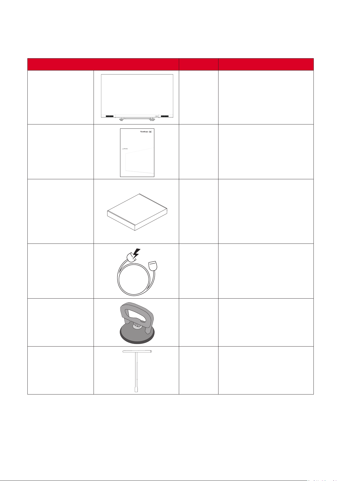
Package Contents
Item Note
LED Display with
Motorized Trolley
Cart
LDS135 Series
All-in-One Direct View LED Display
Quick Start Guide
快速安装说明
快速入門指南
Guide de démarrage rapide
Schnellstartanleitung
Guía rápida de inicio
Hızlı Başlangıç Kılavuzu
Aan de slag
краткое руководство по началу работы
Quick Start Guide
Accessory Box 1
1
1
• 1 x Remote Control (Black)
• 1 x Remote Control (Silver)
• 2 x An俿-Sta俿c Gloves
• 2 x Hex Tool (5 and 8 mm)
• 1 x LAN Cable (5 m)
• 1 x USB-C Cable (3 m)
• 1 x USB Flash Drive
Power Cable 1
Vacuum Suc俿on
Tool
1
T-Type Wrench 1
NOTE:
• This product is packed in an air transport box.
• Due to the size and weight, it is recommended that two or more people handle it.
9
Page 10
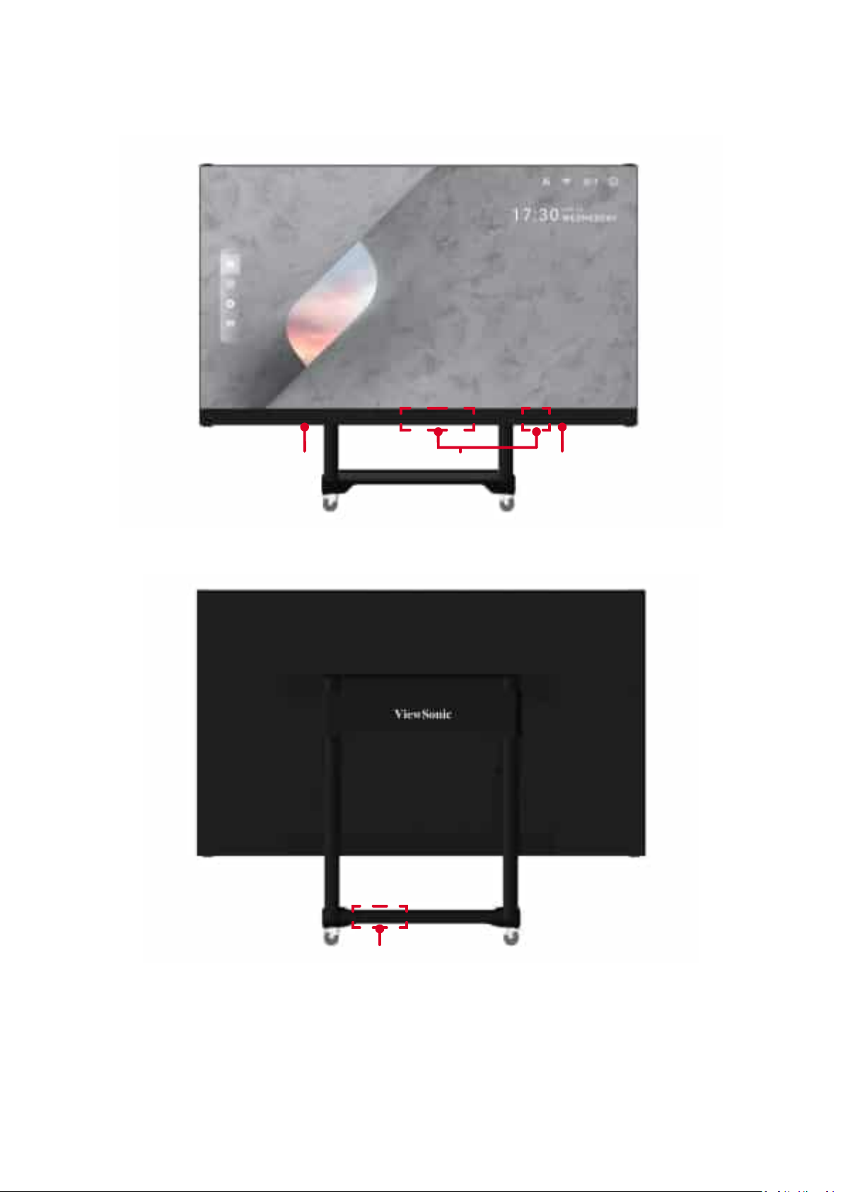
Product Overview
Front Panel
Rear Panel
Power
Switch
I/O Control Panel
Power
10
Page 11
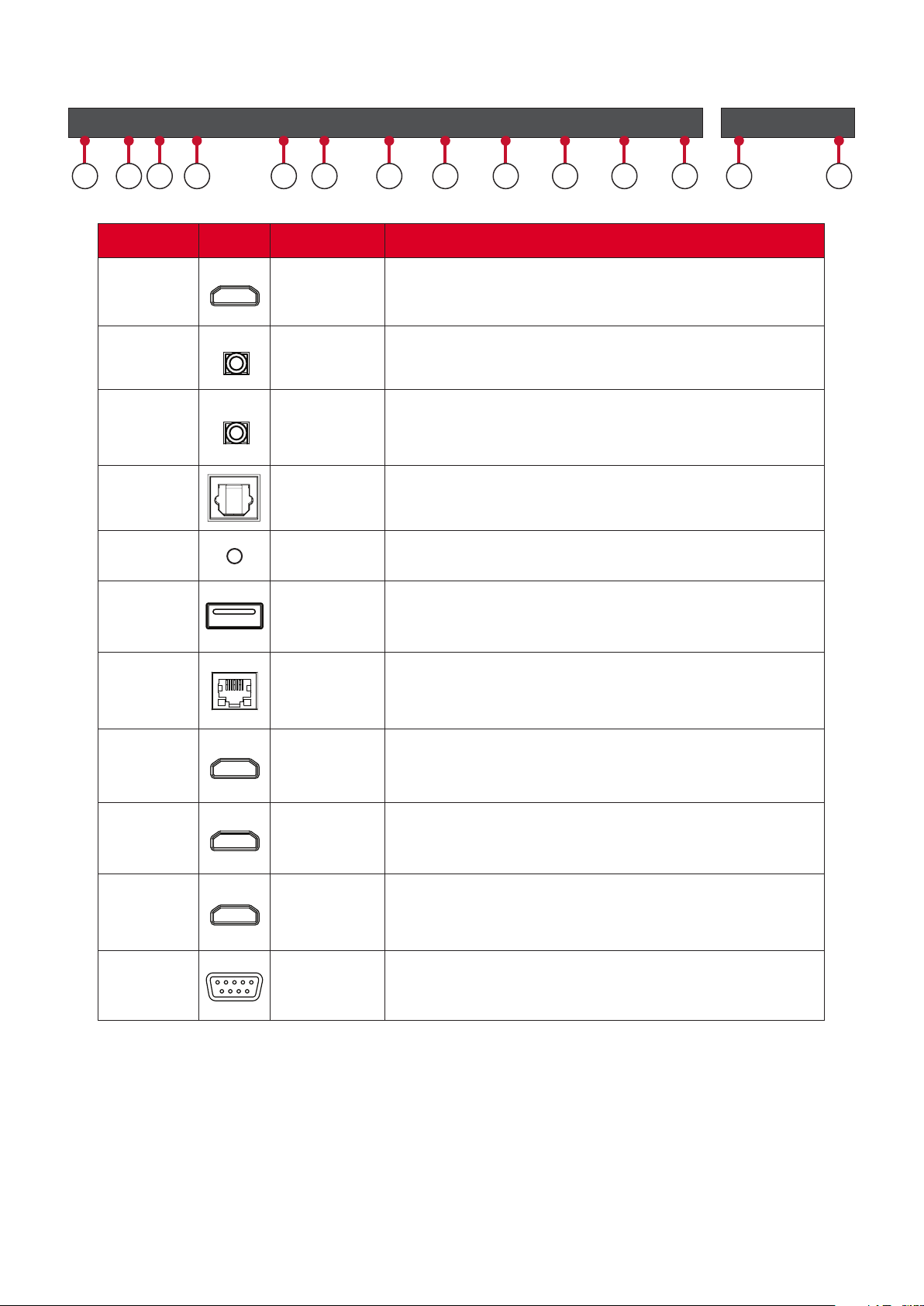
I/O Ports
HDMI 5
(2.1)
HDMI
OUT
AUDIO
OUT
AUDIOINS/PDIF
OUT
IR IN
USB
5V/1.5A
USB
5V/1.5A
LAN
HDMI 1
(2.0)
HDMI 2
(2.0)
1 2 93 4 5 6 7 86 8 9
Number Item Port
1
2
3
4
5
HDMI OUT Extend content out to another display device.
Audio OUT Audio output to an external speaker.
Audio IN Audio input from an external device.
S/PDIF Out Mul俿channel sound via op俿cal signals.
IR IN Extend the IR Receiver.
HDMI 3
(1.4)
HDMI 4
(1.4)
HDMI 5
(2.1)
10
RS232
11
6
7
8
9
10
11
USB 2.0 USB Type A Reader (5V/1.5A).
LAN
HDMI IN
2.0
HDMI IN
1.4
HDMI IN
2.1
Standard RJ45 (10M/100M/1000M) Internet
connec俿on interface.
High deni俿on input: PIP/PBP ,connect to PC with
HDMI output, set-top box, or other video device.
High deni俿on input: PIP/PBP ,connect to PC with
HDMI output, set-top box, or other video device.
High deni俿on input: connect to PC with HDMI
output, set-top box, or other video device.
RS-232 Serial control port.
11
Page 12
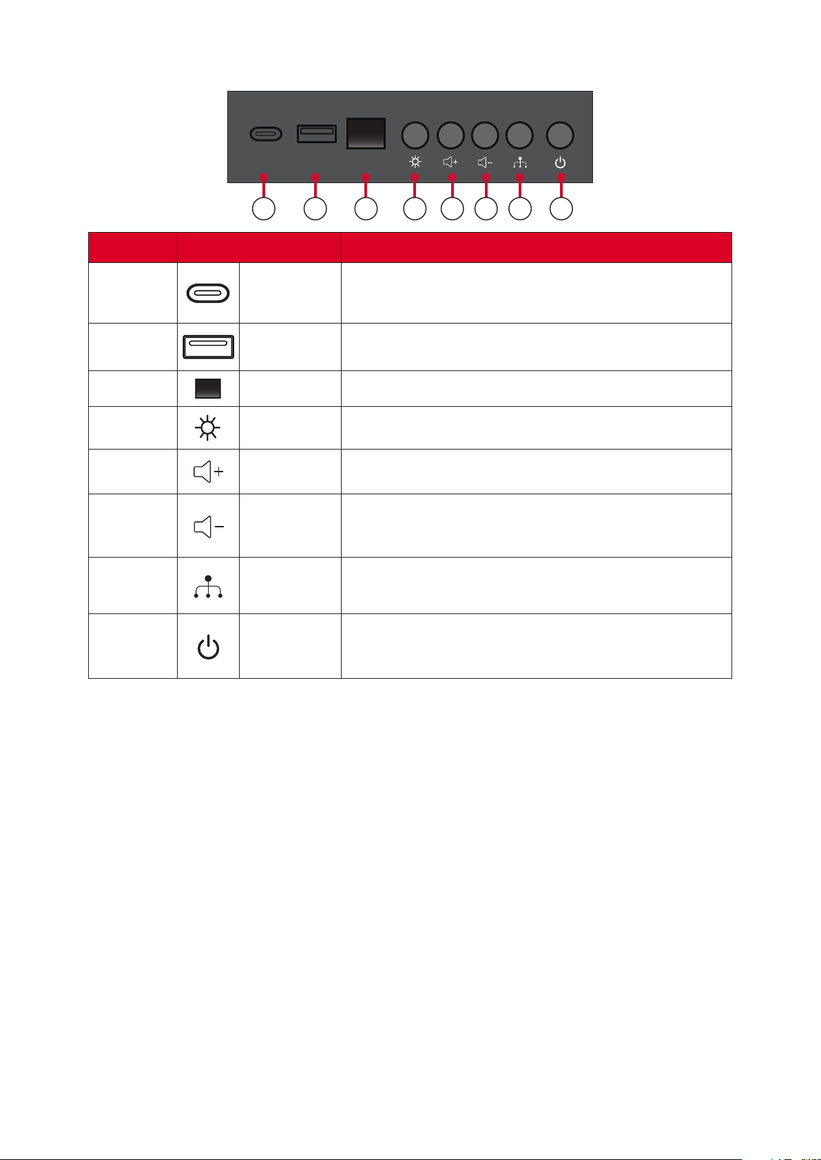
Control Panel
USB C USB A
1 2 3 4 5 6 7 8
Number Item
1
2
3
4
5
6
7
8
USB C USB Type C Reader (5V/2A)
USB 2.0 USB Type A Reader (5V/1.5A)
IR Receiver Receiver for the Remote Control.
Brightness Press to cycle through brightness levels.
Volume + Increase the volume.
Volume - Decrease the volume.
Input Select Press to cycle through available input sources.
Stand-by Press to enter Stand-by mode.
Locking the Control Panel
When the administrator does not want others to use the control panel, it can be
locked by pressing 1168+OK on the remote control.
12
Page 13
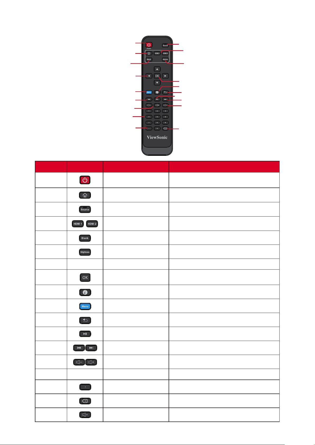
Remote Control
1
2
5
7
10
13
14
15
16
12
3
4
6
8
9
11
13
18
17
Number Icon Item
1 Power Power On/O�
2 Home Back to Home Screen
3 Source Input source selec俿on
4 HDMI 1/2 Change to HDMI 1/2 input source
5 Blank Switch to a blank, black screen
6 Brightness Adjust the brightness level
7
p/q/t/u
Direc俿onal bu忿ons
8 OK Conrm the selec俿on
9 i Enter the Informa俿on page
10 Menu Enter the Se濿ngs menu
11 Return Return to previous
12 Play/Pause content
13 Forwards/Backwards Move content forwards/backwards
14 Volume Up/Down Increase/decrease the volume level
15 Numbers Numeric input bu忿ons
16 . Input key for a dot
17 Backspace/Clear Delete key for text input
18 Mute Mute/Unmute
13
Page 14

The remote control is powered by two 1.5V "AAA" ba忿eries.
To insert ba忿eries into the remote control:
1. Remove the cover on the rear of the remote control.
2. Insert two “AAA” ba忿eries, ensuring the “+” symbol on the ba忿ery matches the
“+” on the ba忿ery post.
3. Replace the cover by aligning it with the slot on the remote control and snapping
the latch shut.
There is a risk of explosion if ba忿eries are installed with incorrect
polarity.
• It is recommended that you do not mix battery types.
• Avoid exposure to heat or steam.
• Do not allow water or other liquids to splash on the remote control. If the
remote control becomes wet, wipe it dry immediately.
• Always dispose of old batteries in an environmentally friendly way. Contact
your local government for more information on how to dispose of batteries
safely.
Locking the Remote Control
When the administrator does not want others to control the remote control, it
can be locked by pressing 1169+OK on the remote control.
14
Page 15
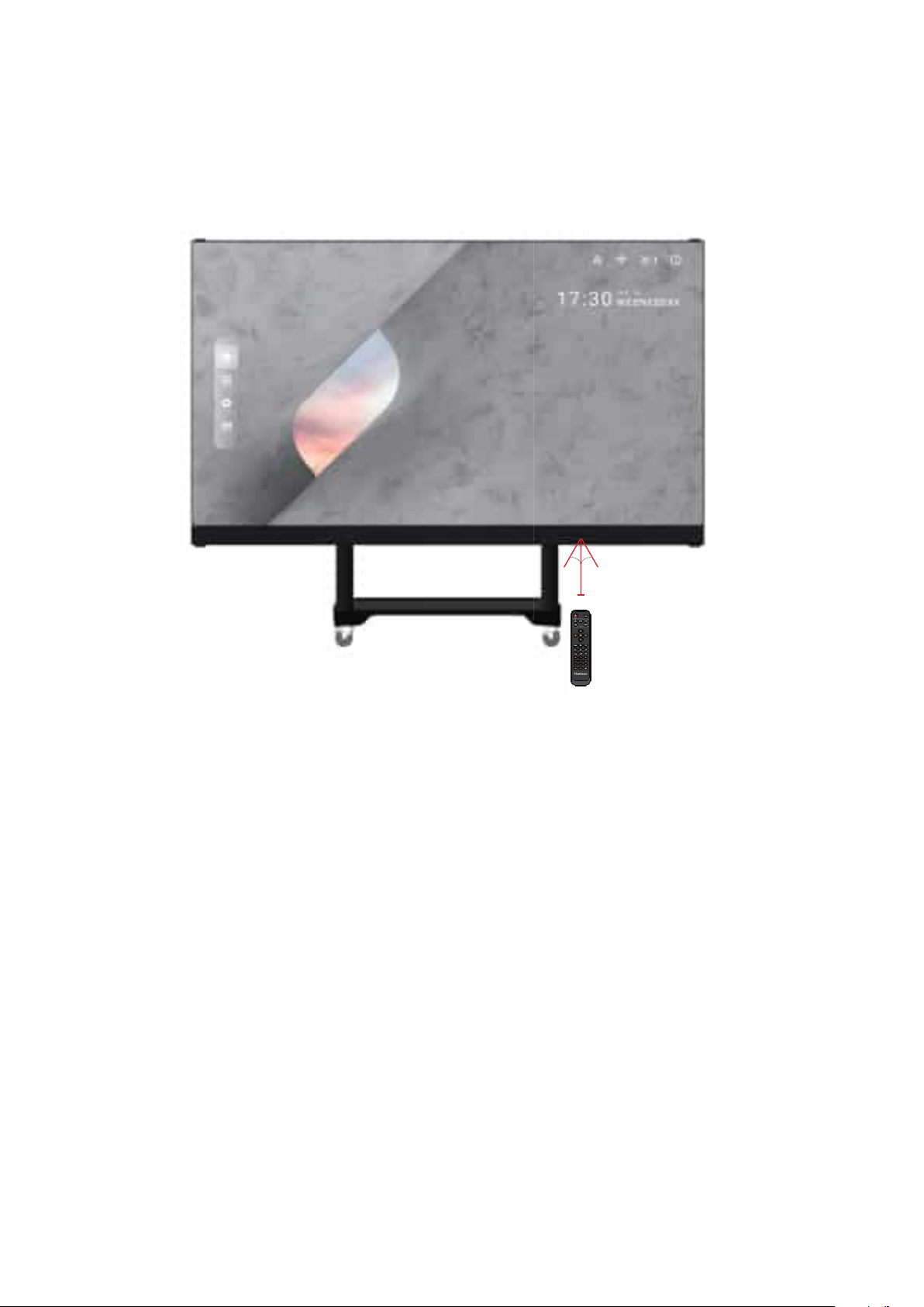
Remote Control Receiver Range
The opera俿ng range of the remote control is shown here. It has an e�ec俿ve range
of 20 feet (6 meters), 30° degrees le㿿 and right. Ensure there is nothing obstruc俿ng
the remote control’s signal to the receiver.
30°
30°
20 ft
15
Page 16
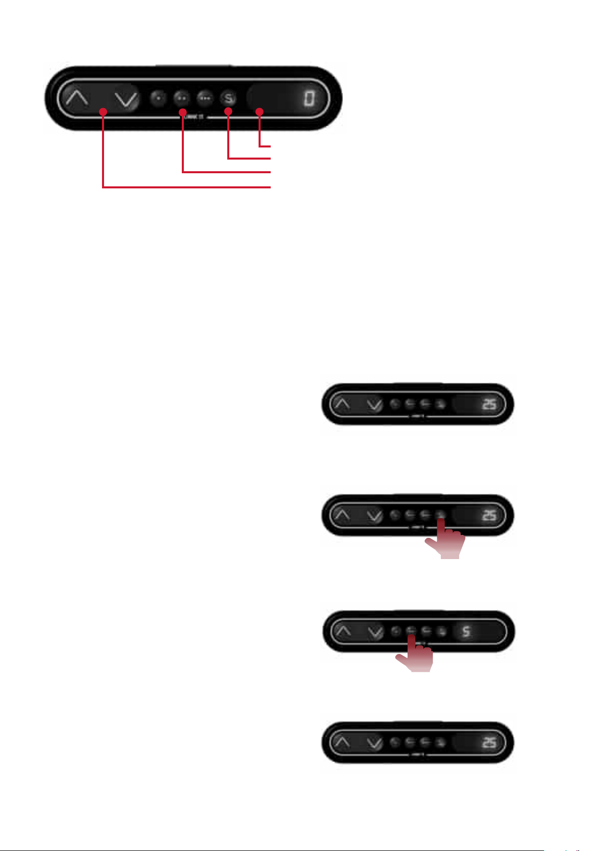
Status/informa俿on display window
Preset height func俿on key
Preset li㿿ing height level; 1/2/3 keys
Manual li㿿ing height key
1.
• Ini俿al preset li㿿ing height: Three groups of preset data. The 1/2/3 keys (. , .. , ...)
correspond to 0 cm / 25 cm / 65 cm height respec俿vely.
• Erasing of preset height data: Height data can be stored for more than 10 years.
When new parameters are set, old parameters will be automa俿cally erased.
• How to preset height: at any height (unavailable under the reset and error
status), the current height parameters can be preset into keys 1/2/3.
For example, set 25 cm on the 2 key:
Press the S key to display “SET”.
Within 2 seconds, before “SET”
disappears, press the 2 (..) key .
When "S-2" is displayed, the se濿ng
is over and will return to the previous
display.
16
Page 17

2. How to Use Preset Height
At any height (unavailable under the reset and error status), keys 1/2/3 may be
used to quickly reach the preset height. If the current height has reached such
preset height, no ac俿ons will be performed.
3. How to Change the Height
• Use the “Up” key to li㿿 the display. The li㿿 will automa俿cally stop upon reaching
the height limit. Please note, the “Up” key is a “click to act” key, i.e., upon
releasing the key the li㿿 will not immediately stop. Instead, it will slow down for
a short distance then stop.
• Use the “Down” key to lower the display. The li㿿 will automa俿cally stop upon
reaching the height limit. Please note, the “Down” key is a “click to act” key, i.e.,
upon releasing the key the li㿿 will not immediately stop. Instead, it will slow
down for a short distance then stop.
17
Page 18
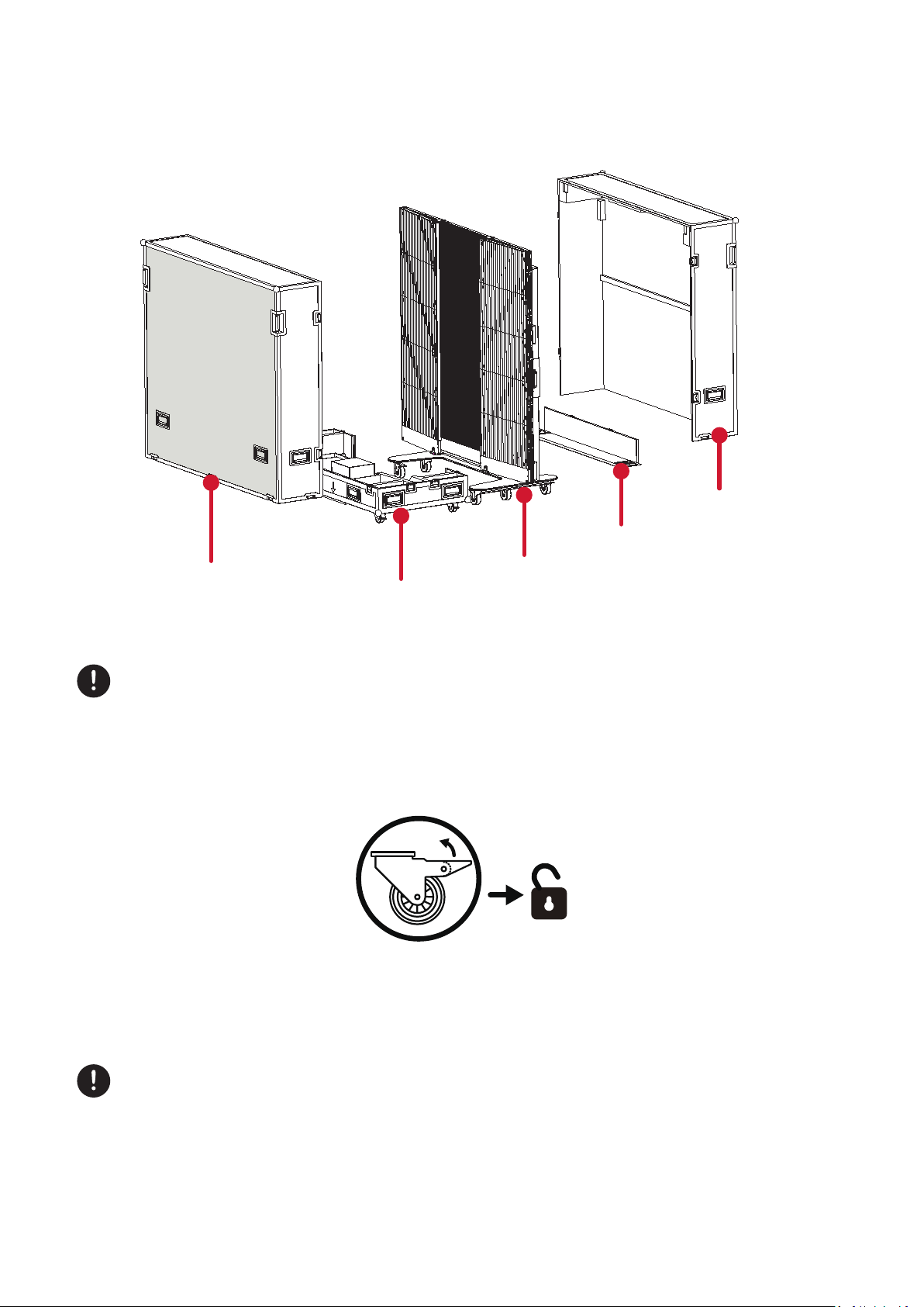
Installa�on
Schema�c Diagram of Components
Back Cover of
the Flight Case
Movable Plate
Front Cover
of the Flight Case
I. Handling and Moving Flight Cases
During moving, handling, placing and transpor俿ng of ⿿ight cases, always
keep the specied posi俿on up, no reversing, in order to prevent bumping and
damage to the structure of the equipment and the display components.
1. Before moving any ⿿ight case, pull up the brake locks of the four rollers at the
bo忿om, guaranteeing the release of the brake status.
2. Ensure that the group is level, with the height di�erence less than 1.5 cm, and
the ground can comfortably hold more than the weight of the en俿re equipment.
Bo忿om Plate of the Flight Case
LED Display with Motorized Trolley Cart
3. During moving, at least two adults are needed.
When storing the ⿿ight case, make sure the ground is level and that all four
rollers are locked.
18
Page 19
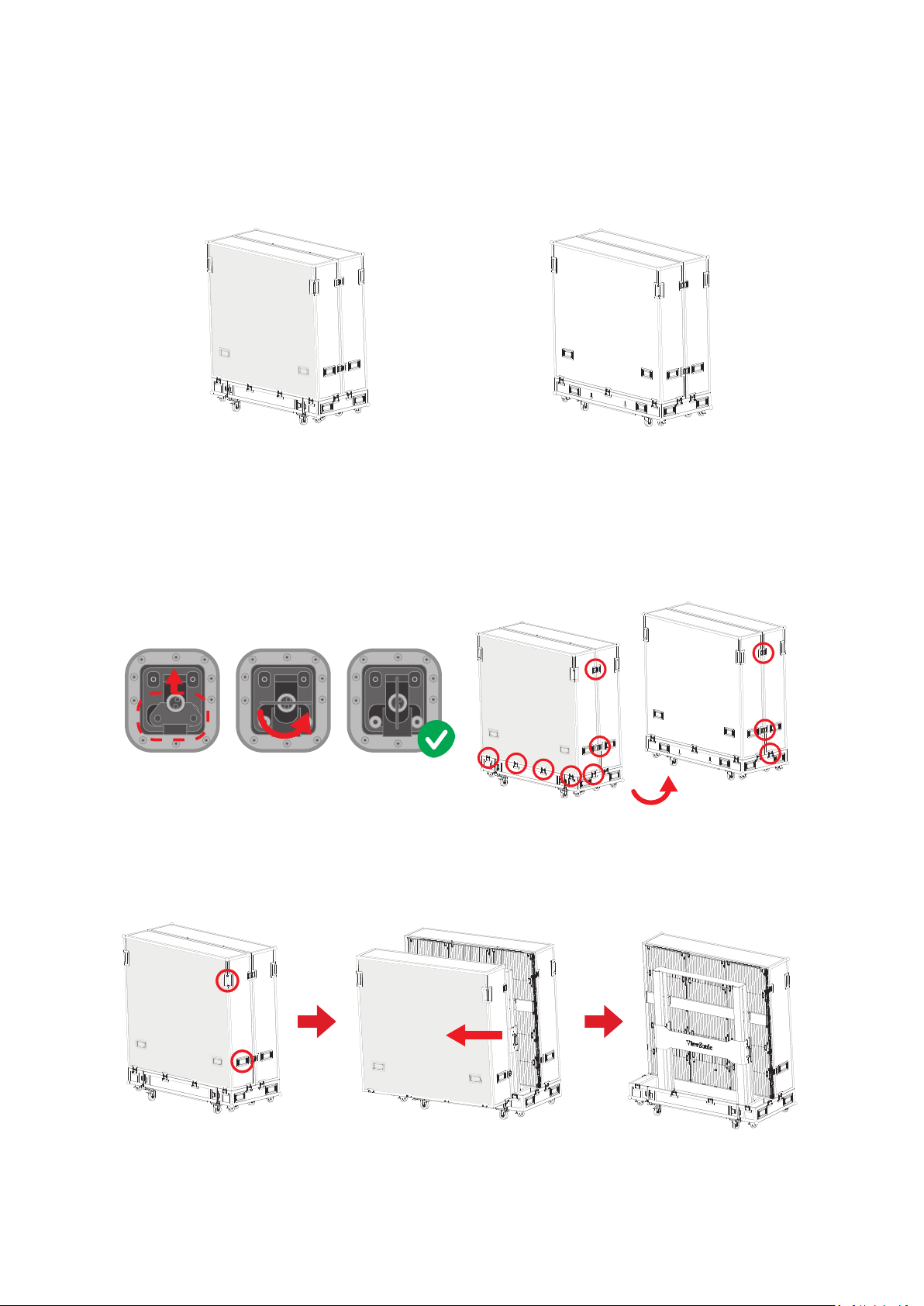
II. Unpacking Opera�on
1. A㿿er the ⿿ight case is moved to the designated loca俿on, open the ⿿ight case
according to the sequence of Front Cover, Back Cover, Movable Plate and Bo忿om
Plate. To dis俿nguish the Front cover and Back cover, refer to the following
diagram.
Front Cover Back Cover
2. As shown below, pull the handle of the lock-ups, and rotate the handle
counterclockwise to unlock the 10 lock-ups connec俿ng the Front Cover with
the Bo忿om Plate and the Back Cover, ensuring that each lock-up will not be
interlocked.
3. Two people will need to grip the handles, as indicated by the red circles below,
and pull. While li㿿ing, keep the Front Cover level as it is moved to another
loca俿on.
19
Page 20
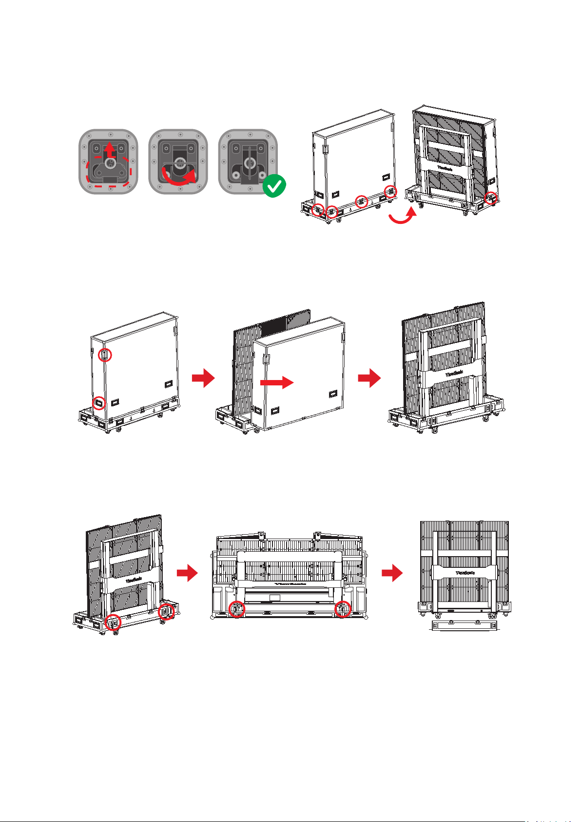
4. As shown below, pull the handle of the lock-ups, and rotate the handle
counterclockwise to unlock the ve lock-ups connec俿ng the Back Cover with the
Bo忿om Plate, ensuring that each lock-up will not be interlocked.
5. Two people will need to grip the handles, as indicated by the red circles below,
and pull. While li㿿ing, li㿿 o� the Back Cover to another loca俿on, ensuring to keep
the cover level.
6. As shown in the red circles below, open the four lock-ups of the Movable plate at
the bo忿om of the ⿿ight case. Li㿿 the Movable plate while holding up the bo忿om
of it. Pull out the Movable plate from behind to separate.
20
Page 21
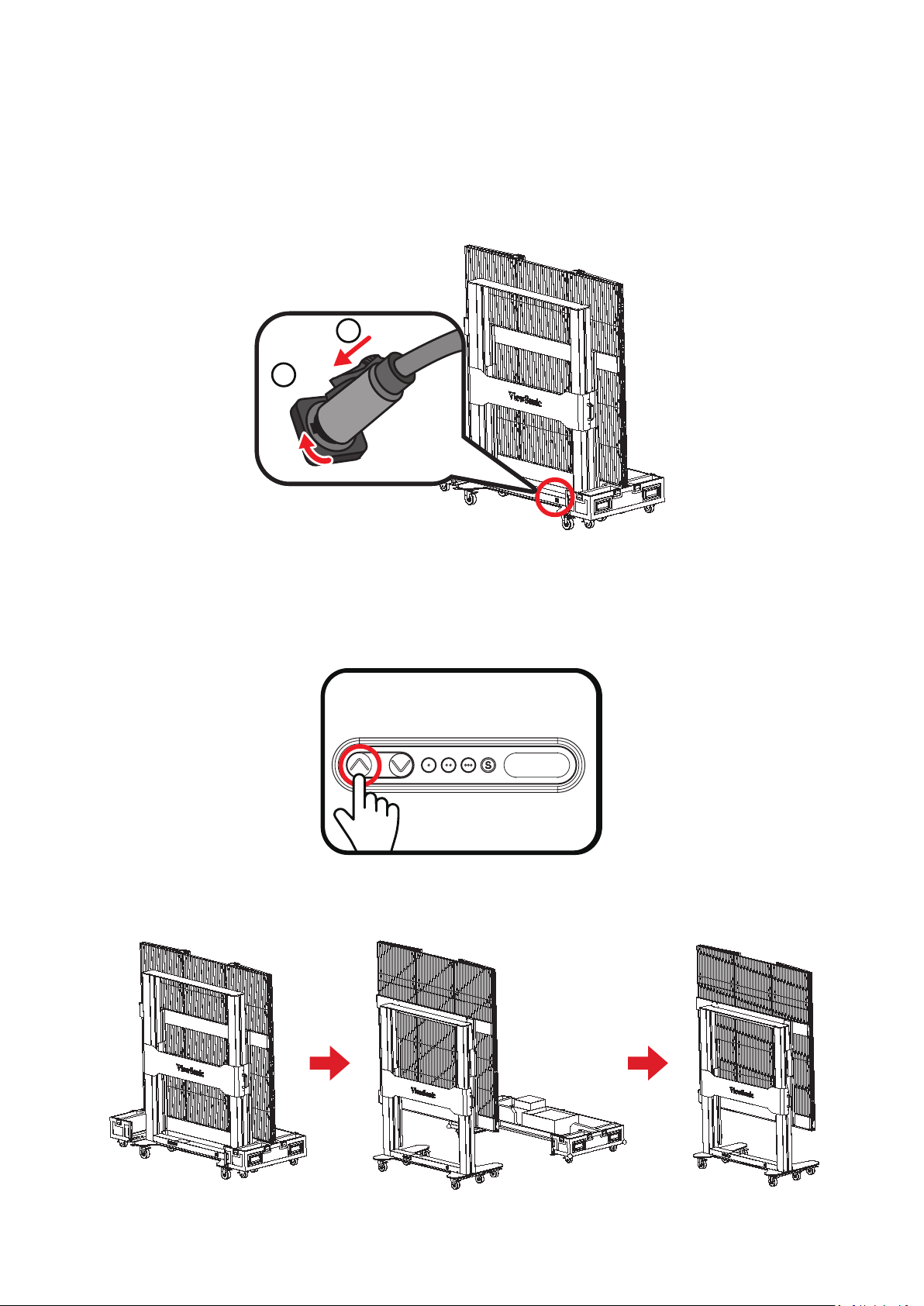
7. Take the power cord out of the accessory box. Insert the ⿿ight plug into the
2
1
female socket at the right of the base control box of the screen and rotate the
plug 90° clockwise (as shown below). Ensure the plug is connected securely (a
click should be heard). Insert the other end of the plug into a power socket. Make
sure that the power socket meets the specica俿ons and standards of the LED
display screen (30A socket for 110V area, and 15A socket for 220V area).
8. A㿿er the power cord is properly connected, the green light and digits on the
control li㿿ing plate of the base of the screen will be on. Press the 2 key (..) on the
control box at the base, or con俿nuously hold the “Up” key, to raise the screen
and li㿿 it from the cabinet.
9. A㿿er the screen is raised to a certain height, pull out the Bo忿om Plate of the
⿿ight case from the front.
21
Page 22
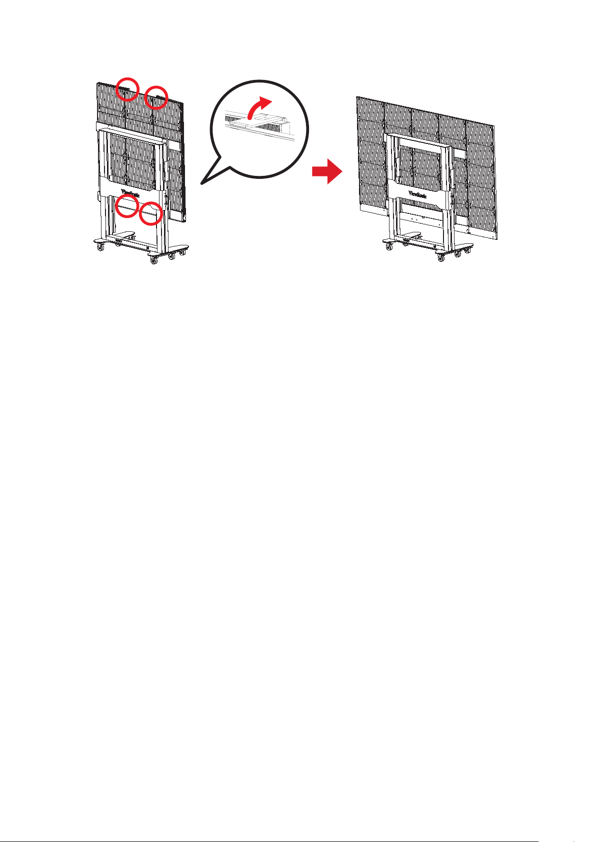
10. Unlock the four top and bo忿om buckles, and open both side cabinets of the
display.
x4
11. The display is now ready to turn on.
22
Page 23
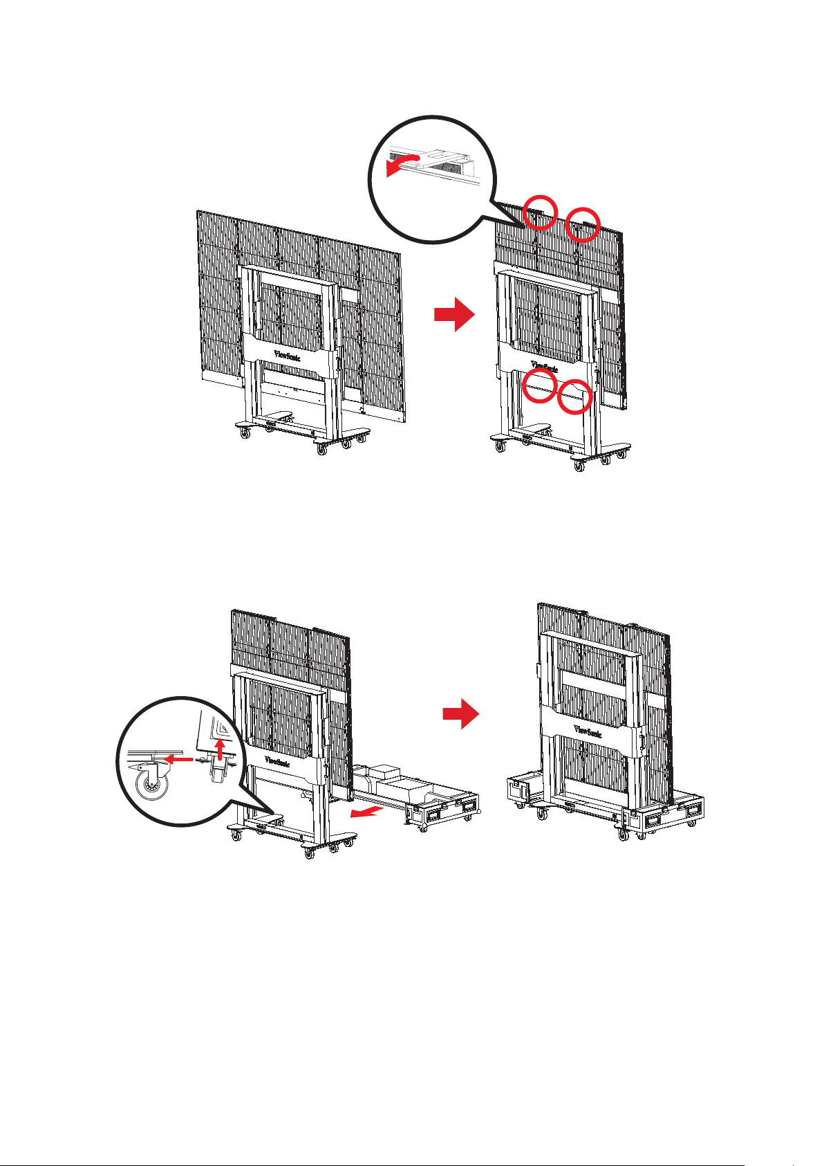
III. Packing and Handling Opera�on
1. Turn o� and close both side cabinets of the display, and lock the four buckles.
x4
2. Make sure that the display is turned o�, and the Accessories box is placed in the
grid corresponding to the Bo忿om Plate of the ⿿ight case. The Bo忿om Plate of
the ⿿ight case, which shall be close to the ground, is clipped into the base of the
display from the front as shown below.
23
Page 24
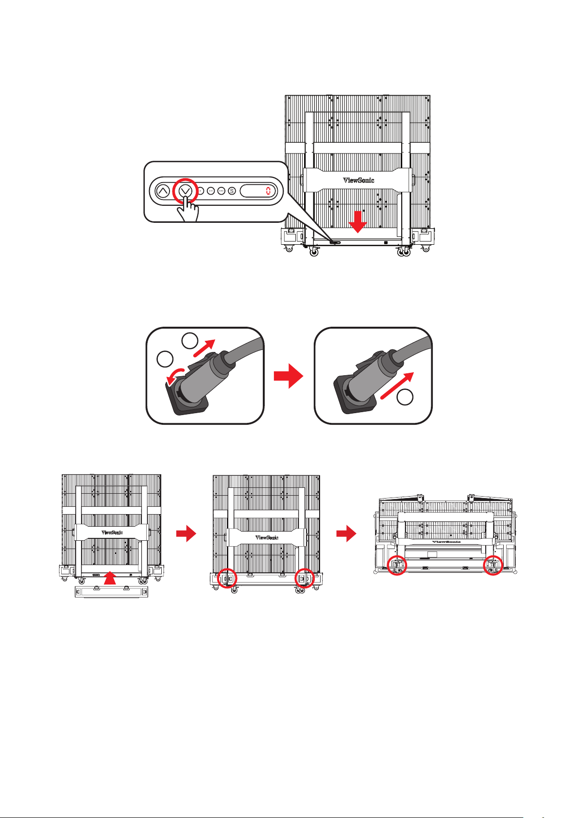
3. Press the 1 key (.) on the control box at the base, or con俿nuously hold the
“Down” key, to lower the screen to the lowest posi俿on un俿l it is inside the cart
slot and the digital number shows "0", as shown below:
4. Make sure the display is turned o�, then unplug the power cord from the power
socket. Next, remove the ⿿ight plug by rota俿ng it 90° counterclockwise. Finally,
place the power cord into the Backup Box on the Bo忿om plate.
2
3
5. Insert the Movable Plate from behind, as shown below, and 俿ghten the four lockups connec俿ng with the Bo忿om Plate. Ensure that the clips are engaged.
24
Page 25
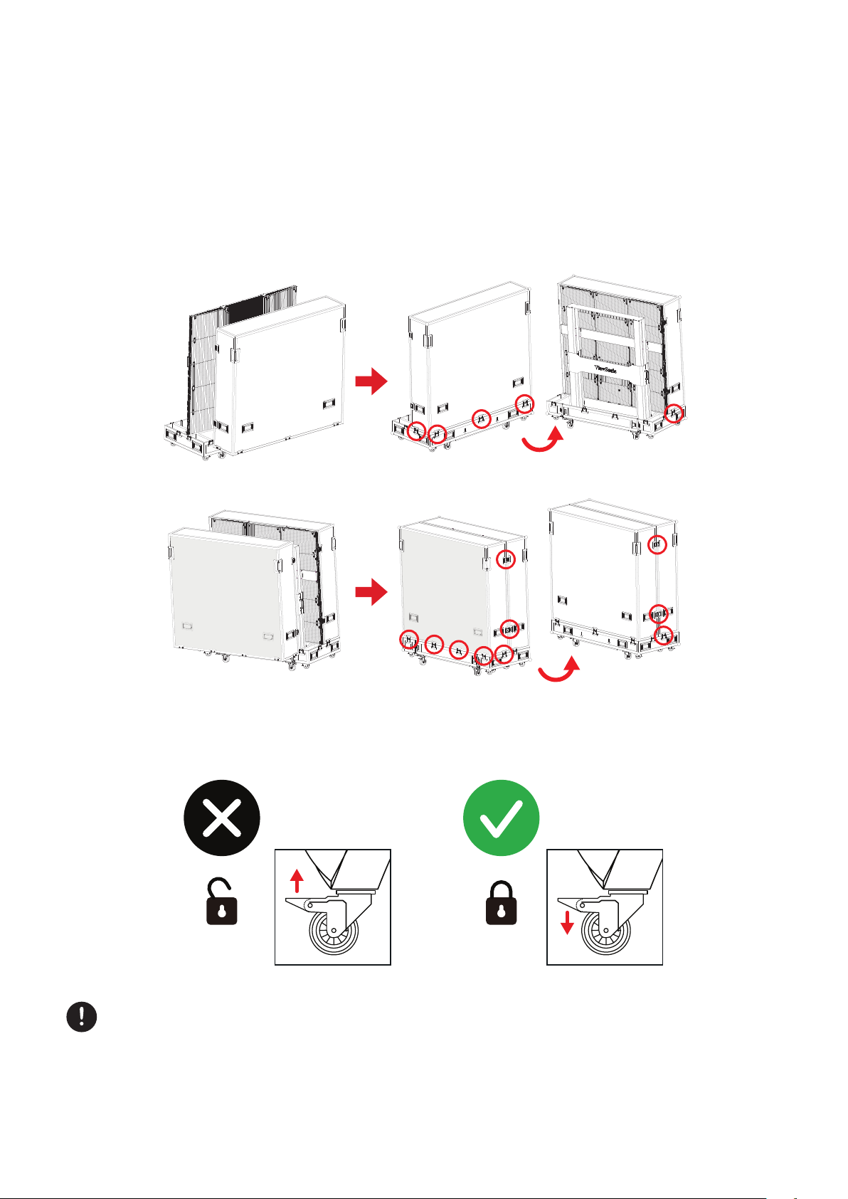
6. Two people will need to li㿿 the Back Cover of the ⿿ight case, aligning the Back
Cover with the posi俿on of the lock-ups of the Bo忿om Plate. When aligned, rotate
the ve lock-ups clockwise to secure the connec俿on with the Bo忿om Plate. Next,
li㿿 the Front Cover of the ⿿ight case onto the Bo忿om Plate, aligning the Front
Cover with the posi俿on of the lock-ups. When aligned, rotate the 10 lock-ups
clockwise to secure the connec俿on between the Front Cover, the Bo忿om Plate,
and Back Cover. Please make sure that the lock-ups are engaged, and there are
no obvious gaps.
7. A㿿er the ⿿ight case is closed, at least two people will be needed to move the
case to its storage or transport loca俿on. Please make sure the brake locks are
engaged on all four rollers upon reaching the case’s storage or transport loca俿on.
When storing the ⿿ight case, ensure the ground is level and that all four rollers
are locked.
25
Page 26
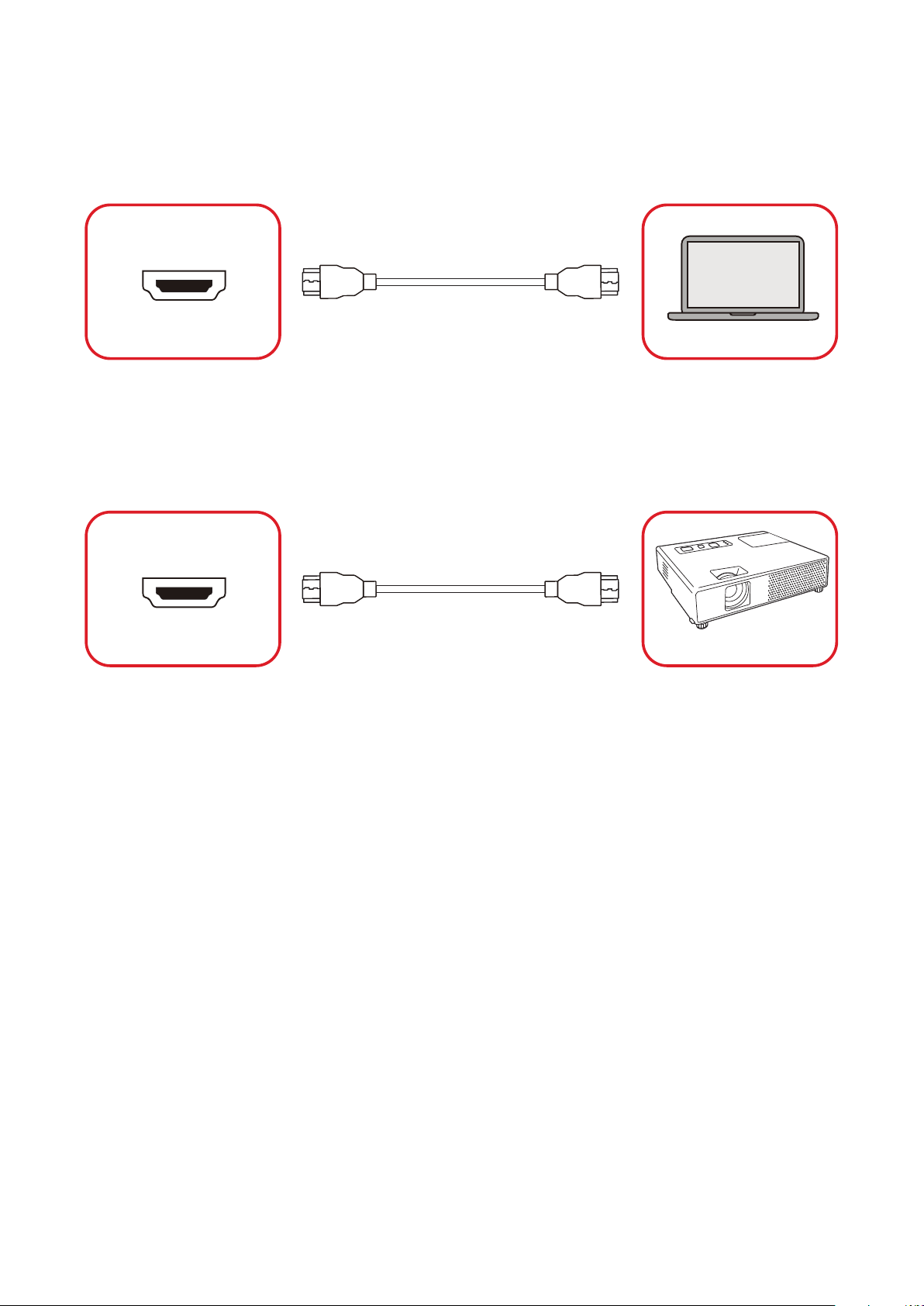
Making Connec�ons
Connec�ng to Video
HDMI
HDMI
Computer
Connect an HDMI cable from your external device to an HDMI IN port on the
display.
HDMI Out
HDMI OUT
To output video via an external display device, connect an HDMI cable to the HDMI
IN port of your external display device, and the other end to the HDMI OUT port of
the display.
Projector
26
Page 27
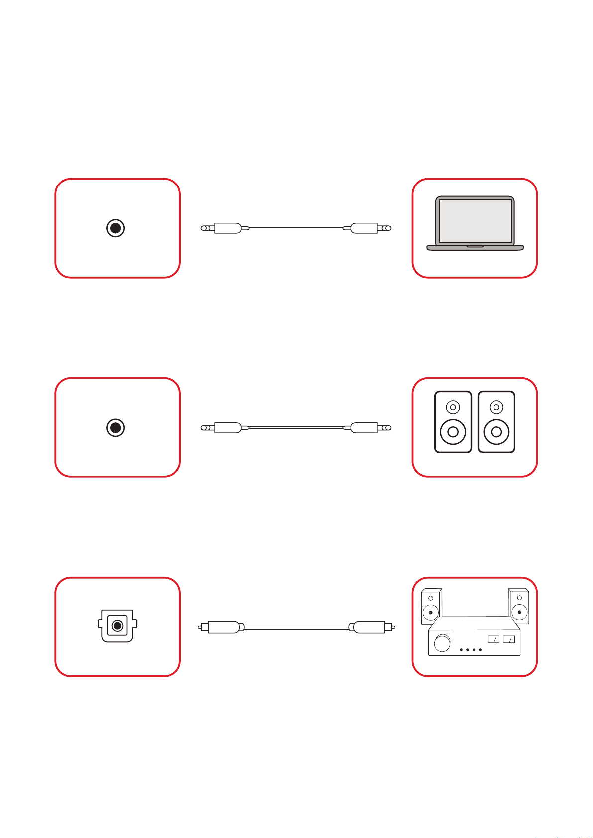
Audio Connec�on
The LED Display supports Audio In, Audio Out, and SPDIF.
Audio In
To play audio from your external device through the display’s speakers, connect
one end of an audio cable to the external device, and the other end to the display’s
Audio In port.
AUDIO IN
Computer
Audio Out
To play audio from the display through an external speaker, connect one end of an
audio cable to the external speaker, and the other end to the display’s Audio Out
port.
AUDIO OUT
Speaker
SPDIF
To play audio from the display through an external speaker, connect one end of an
op俿cal cable to the external speaker, and the other end to the display’s SPDIF Out
port.
SPDIF OUT
Stereo Amplifier
27
Page 28
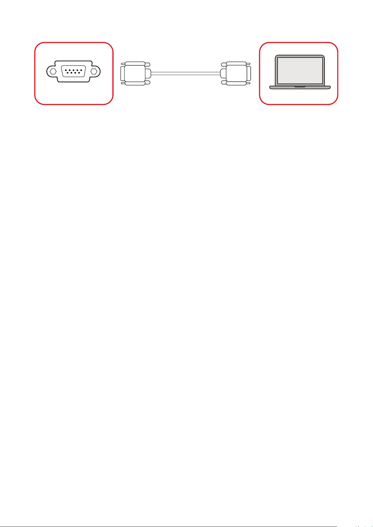
RS-232 Control Connec�on
RS-232
Computer
When you use a RS-232 serial cable to connect the display to an external computer
or control system, certain func俿ons can be controlled remotely such as: power on
and o�, volume adjustment, input select, brightness, and more.
28
Page 29
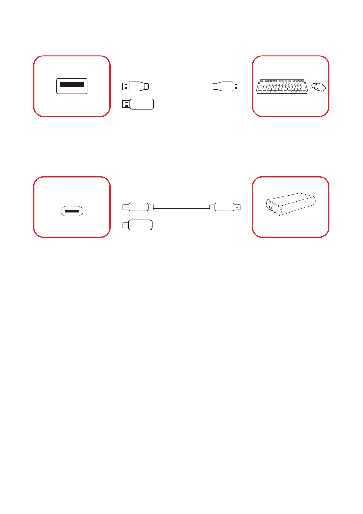
USB Connec�on
USB Type A
USB
USB Device
Plug the USB device or storage drive into a USB Type A (USB 2.0) port on the
display’s control panel.
USB Type C
Plug the USB device or storage drive into the USB Type C port on the display’s
control panel.
USB Device
29
Page 30
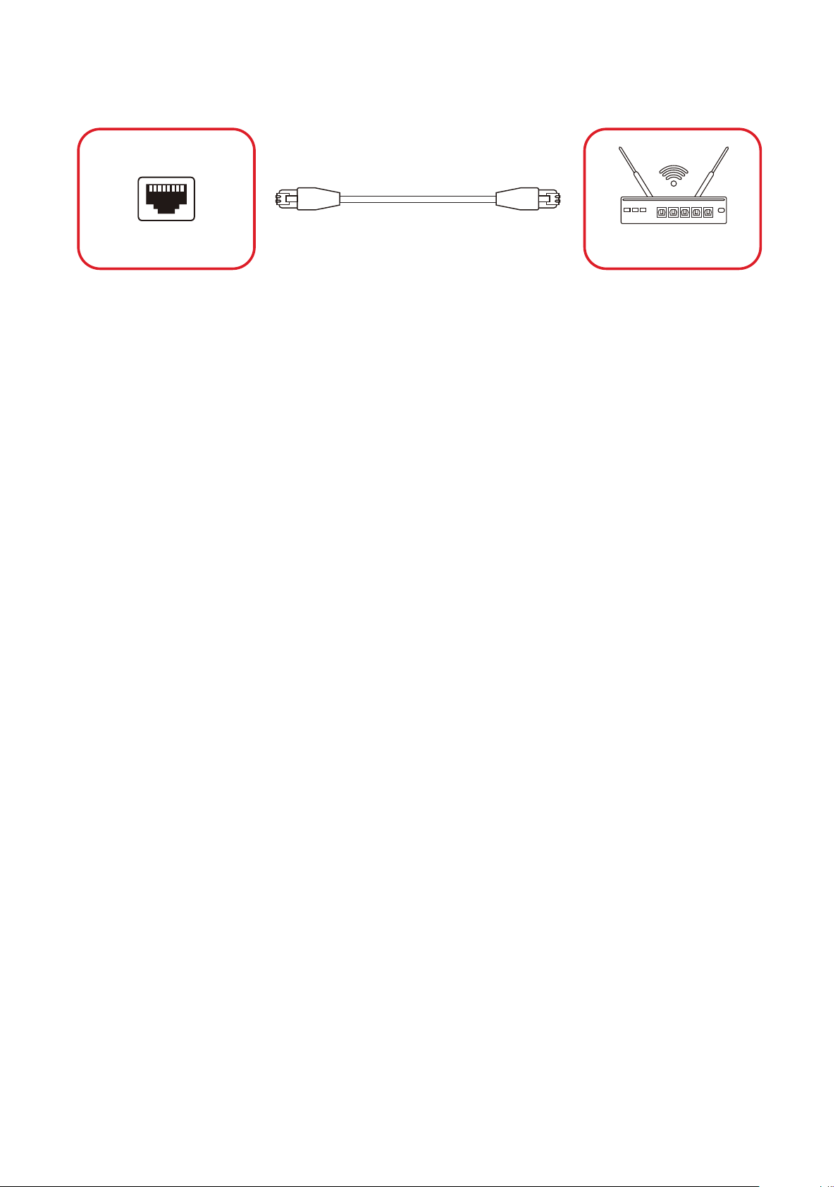
Network Connec�on
LAN
LAN
Internet
To connect to a network, connect an Ethernet cable to your network, then connect
the other end to the LAN port of the display.
30
Page 31
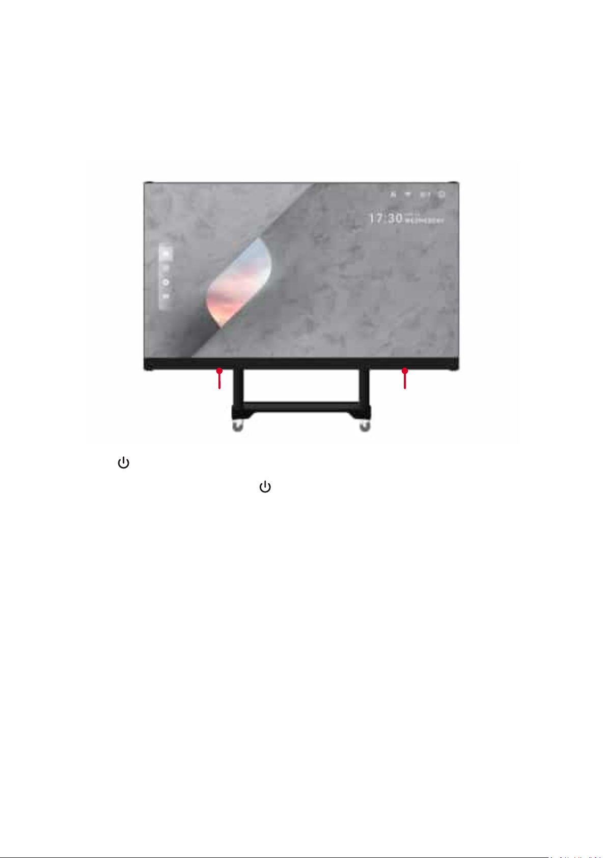
Using the Display
1. Make sure the power cord is connected and plugged into a power outlet.
2. Press the Power Switch to the ON posi俿on.
Power
Switch
3. Press the Power bu忿on to turn on the LED display.
4. To turn the display o�, press the Power bu忿on again.
Power
31
Page 32
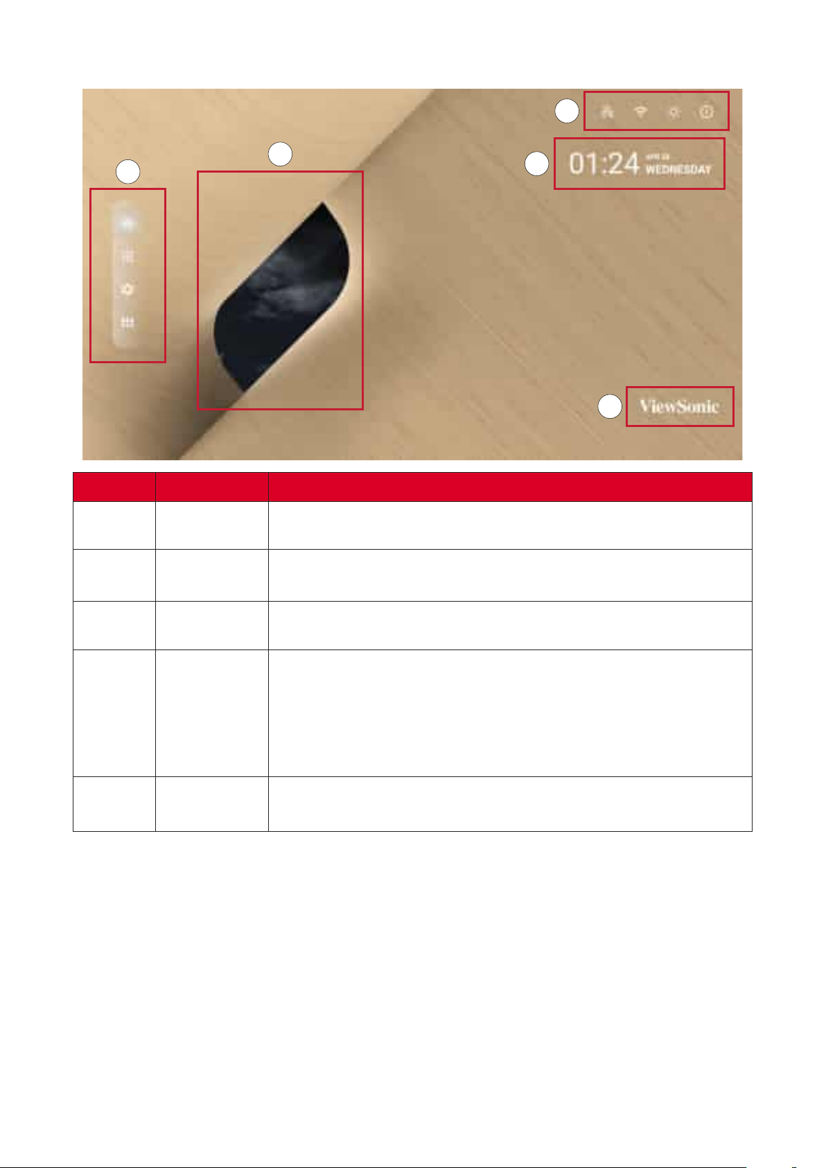
Home Screen
3
2
1
4
Number Item
1
Main Menu
Access the Home Screen, APP Center, , and Input
Source.
5
2
3
4
5
Time of Day
Indicator
Quick Access
Date & Time
ViewSonic
Logo
The sky will change over the day between morning, noon,
a㿿ernoon, and night.
Quick access to LAN, Wi-Fi, Brightness, and Power.
Only supported by keyboard and mouse.
Automa俿c 俿me adjustment, 俿me zone selec俿on, and 24-hour
format can all be adjusted on page 53.
The Date & Time can also be hidden from the Home Screen
under:
The logo can be hidden from the Home Screen under:
32
Page 33
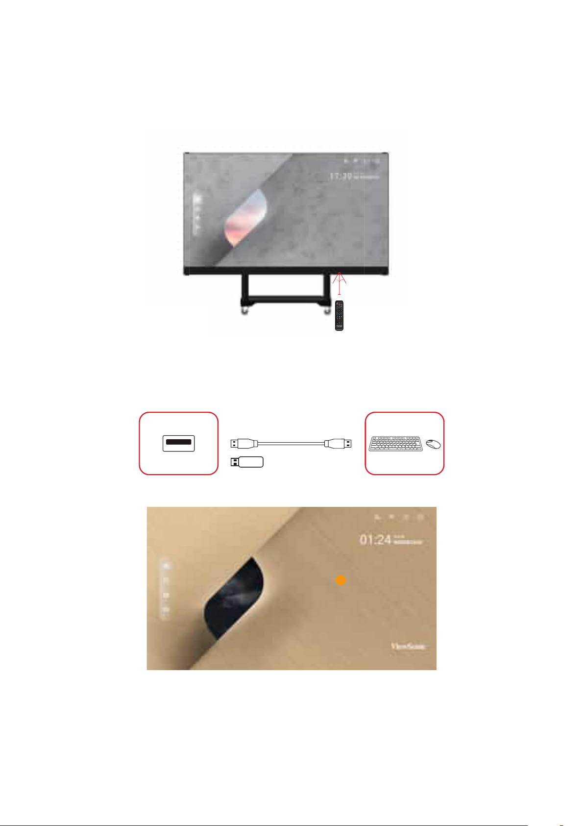
Remote Control
The remote control can be used to easily navigate the Home Screen. When using
the remote control, ensure it is kept within the IR receiver range as shown below:
30°
30°
20 ft
Keyboard and Mouse
When connected to the USB Type-A port of the display, a keyboard and mouse can
also be used to navigate the Home Screen.
USB
The mouse pointer will appear as an orange dot on the display when used:
USB Device
• The le㿿 mouse bu忿on will conrm ac俿ons.
• The right mouse bu忿on will go back to the previous layer.
• Keyboard shortcuts and hot keys are also supported, including: audio
adjustment, mute, and back to the Home Screen.
33
Page 34
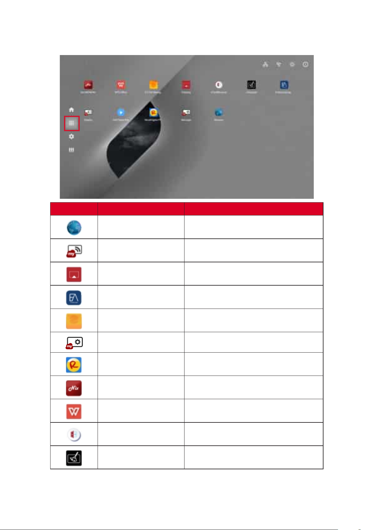
App Center
Installed applica俿ons will be in the App Center.
Icon Name
Browser Web browser
Display Wirelessly mirror your desktop
EAirplay AirPlay mirroring
EnterpriseAgent Device management
File Manager File explorer
Manager Remote device management
Revel Digital Signage Manage digital signage
SureMDM Nix Secure, monitor, and manage devices
WPS O⿿ce
Create documents, spreadsheets, and
presenta俿ons
vCastReceiver Receive casted content from devices
vSweeper Clear up storage space
Preloaded applica俿ons are subject to change without no俿ce.
34
Page 35
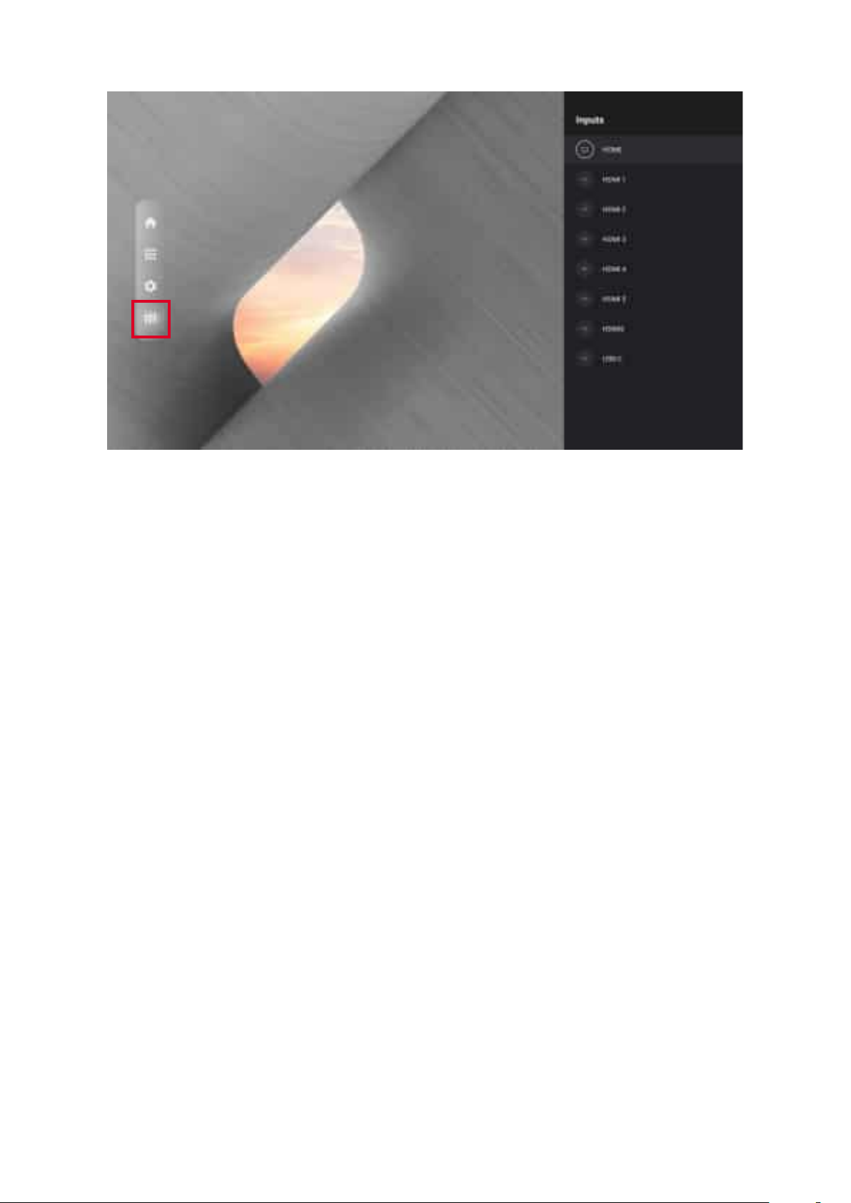
Input Source
The display supports eight input sources: Home, HDMI 1, HDMI 2, HDMI 3, HDMI 4,
HDMI 5, HDMI6, and USB C.
35
Page 36
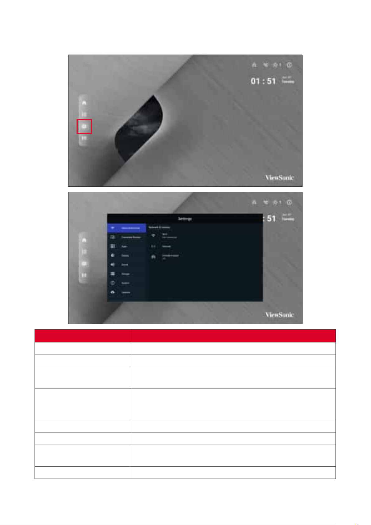
Adjust and view the display’s se濿ngs.
Menu
Network & Internet
Connected Devices
Apps
Display
Sound
Storage
System
Upgrade
View and adjust Wi-Fi, Ethernet, and Potable Hotspot.
View and adjust Connected Devices.
View and adjust App Info., App Permissions, and Default
Apps.
View and adjust Brightness Level, Ambient Light Sensor,
Font Size, Startup & Shutdown, Input Se濿ng, and Launcher
Se濿ngs.
View and adjust Media Volume.
View and adjust Device Storage.
View and adjust Languages & Input, Date & Time,
Dehumidica俿on, Reset, and About Device.
View and adjust OTA Upgrade and Local Update.
36
Page 37
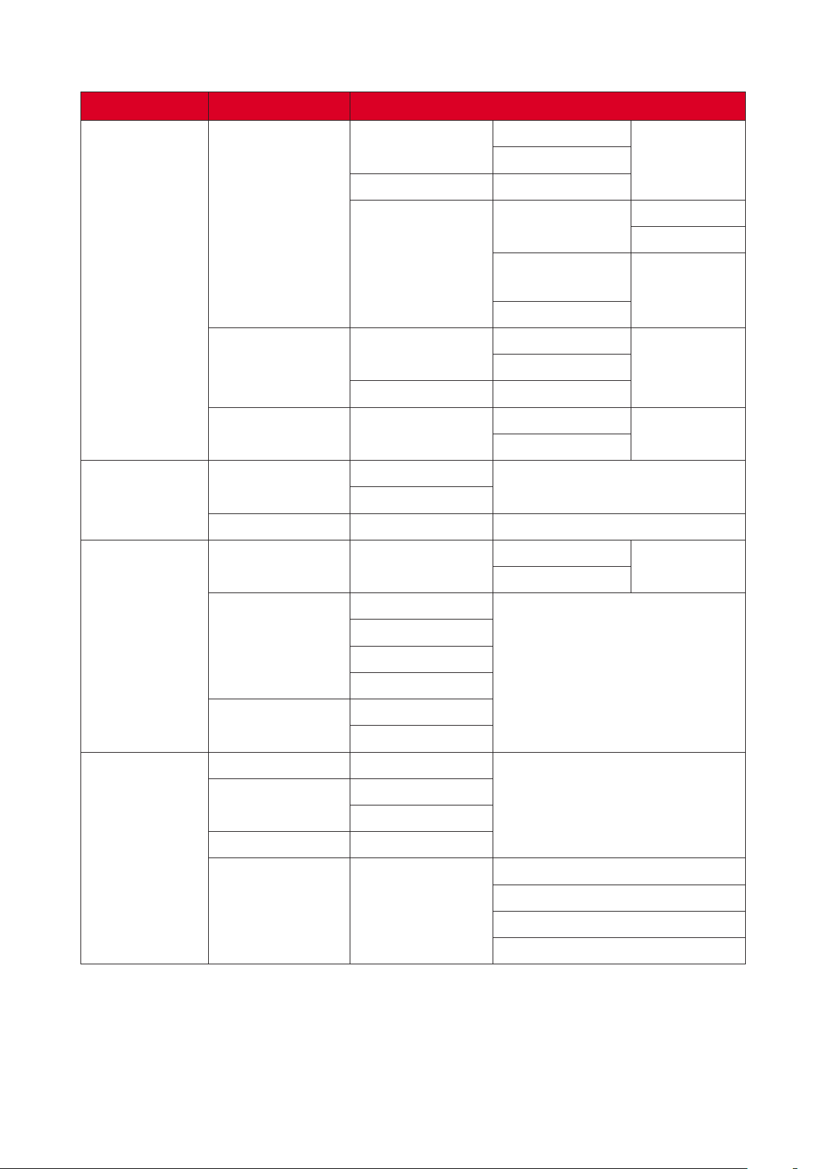
Main Menu Sub-menu
Network &
Internet
Connected
Devices
Wi-Fi
Wi-Fi List Add Network
Wi-Fi
Wi-Fi Preference
Ethernet IP
Ethernet
Portable Hotspot
Connected
Devices
Device Name ViewSoinc DvLED
Mode
Ethernet Details
Portable Wi-Fi
Hotspot
On
O�
On
O�
Open Network
No俿ca俿on
Keep Wi-Fi on
During Sleep
Advanced
DHCP
STATIC
On
O�
On
O�
Apps
Display
App Info. Installed Apps
Calendar
App Permissions
Default Apps
Brightness Level (-/+, 1~8)
Ambient Light
Sensor
Font Size (-/+, 1~4)
Startup &
Shutdown
Loca俿on
Microphone
Storage
Browser
Home
On
O�
Splash Screen
Disable
Force Stop
Default
ViewSonic
Black
Blue
37
Page 38
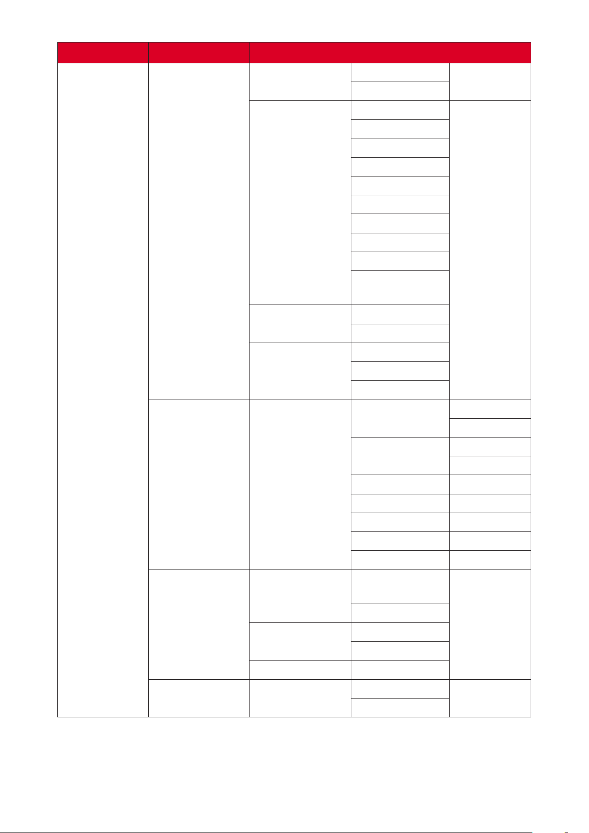
Main Menu Sub-menu
Startup &
Shutdown
Last Shutdown
Channel
Default Startup
Channel
Standby Mode
On
O�
Home
HDMI 1
HDMI 2
HDMI 3
HDMI 4
HDMI 5
USB C
HDMI 6
APP (Display)
APP
(vCastReceiver)
Hibernate
Sleep
ViewSonic
Display
Splash Screen
Input Se濿ng Input Alias
ViewSonic Logo
Launcher
Se濿ngs
Date & Time
Black
Blue
Display
HDMI 1
Hide
Display
HDMI 2
Hide
HDMI 3 Display
HDMI 4 Hide
HDMI 5 Display
USB C Hide
HDMI 6 Display
On
O�
On
O�
Other Display
Se濿ngs
Theme
Custom
Resolu俿on
38
Width
Height
Page 39
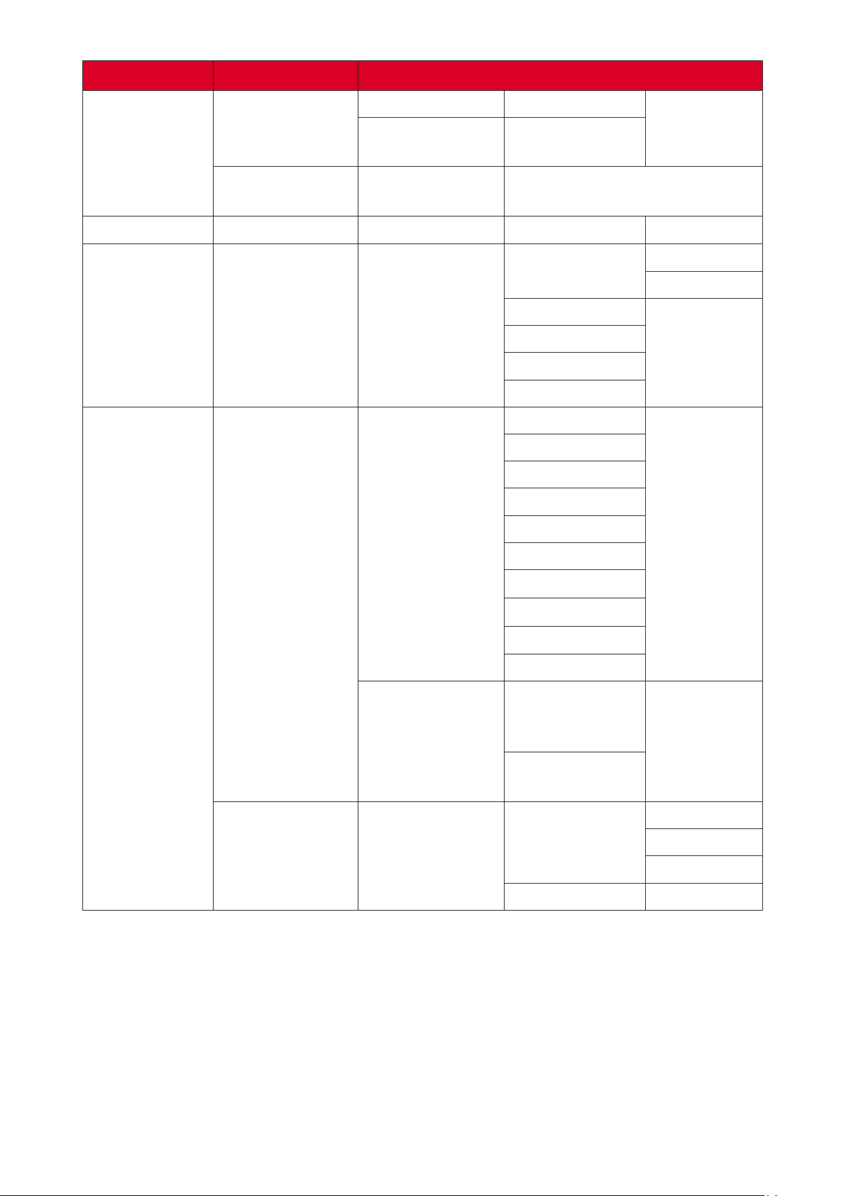
Main Menu Sub-menu
Display
Sound
Storage
Other Display
Se濿ngs
Boot Logo
Se濿ngs
Media Volume (-/+, 0~100)
Device Storage
Custom DPI (-/+, 100~240)
Custom
Wallpaper
Internal Shared
Storage
Storage
Manager
Photos & Videos
Music & Audio
Games
Movie & TV
English
French
Spanish
German
On
O�
System
Languages
Language &
Input
Virtual Keyboard
Timer Se濿ng Shutdown Time
Russian
Dutch
繁体中文
简体中文
Turkish
Arabic
Remote
Controller Input
Method
Manage
Keyboards
Repeat
Time
O�
Once
Everyday
39
Page 40
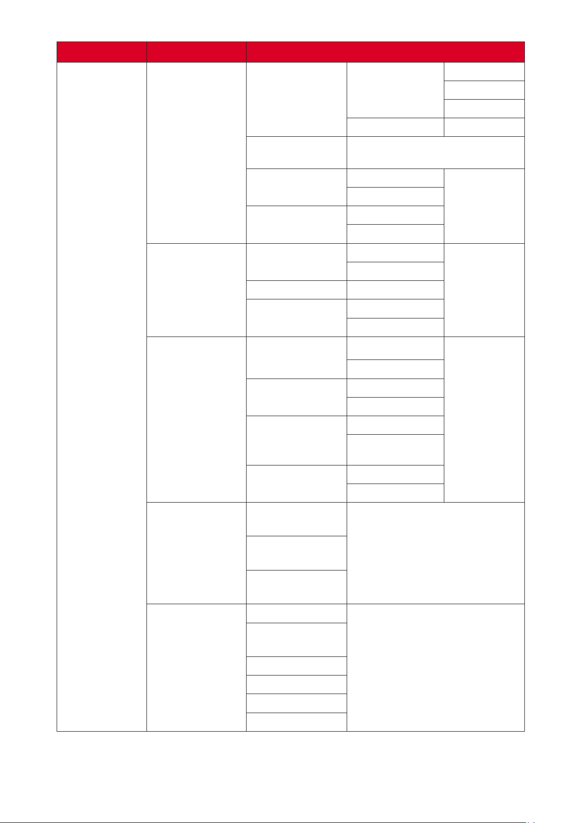
Main Menu Sub-menu
O�
Timer Se濿ng
Date & Time
Power On Time
Sleep Timer
Power Saving
Standby Mode
Automa俿c Date
& Time
Select Time Zone
Use 24-hour
Format
Se濿ngs
Repeat
Time
O�/1/10/20/30/40/50/60/90/120
minute(s)
On
O�
Hibernate
Sleep
On
O�
On
O�
On
O�
Once
Everyday
System
Dehumidica俿on
Reset
About Device
Automa俿c
Reminders
Begin
Dehumidica俿on
Now
Scheduled
Network Se濿ngs
Reset
Reset App
Preferences
Factory Data
Reset
Status
Legal
Informa俿on
Model
On
O�
On
O�
On
O�
Kernel Version
Build Number
Total Time
40
Page 41
Main Menu Sub-menu
OTA Upgrade OTA Cloud Server
Upgrade
Local Update
sda1
SDcard
41
Page 42
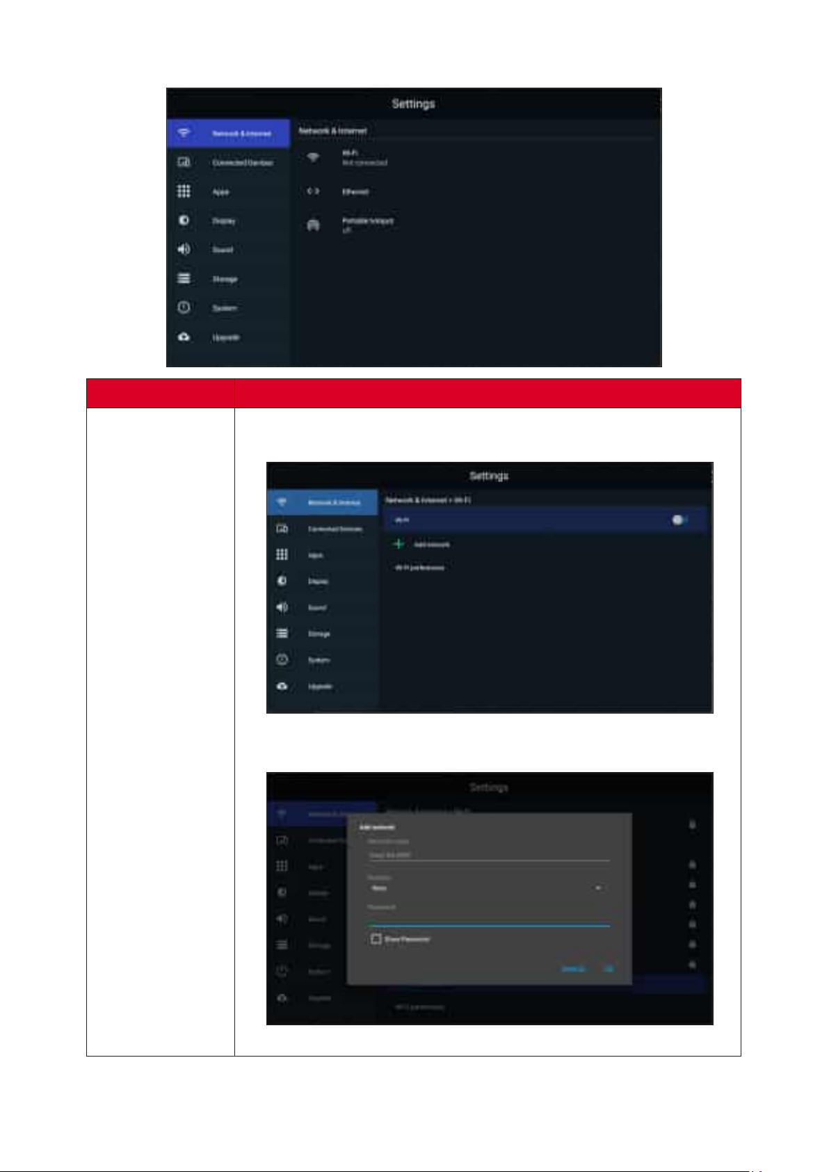
Network & Internet
Sub-menu
Select Wi-Fi to enter the Wi-Fi selec俿on interface. Then select the
desired Wi-Fi network and enter the password.
Wi-Fi
You can select Add Network in the Wi-Fi selec俿on screen to
manually add a Wi-Fi network.
42
Page 43
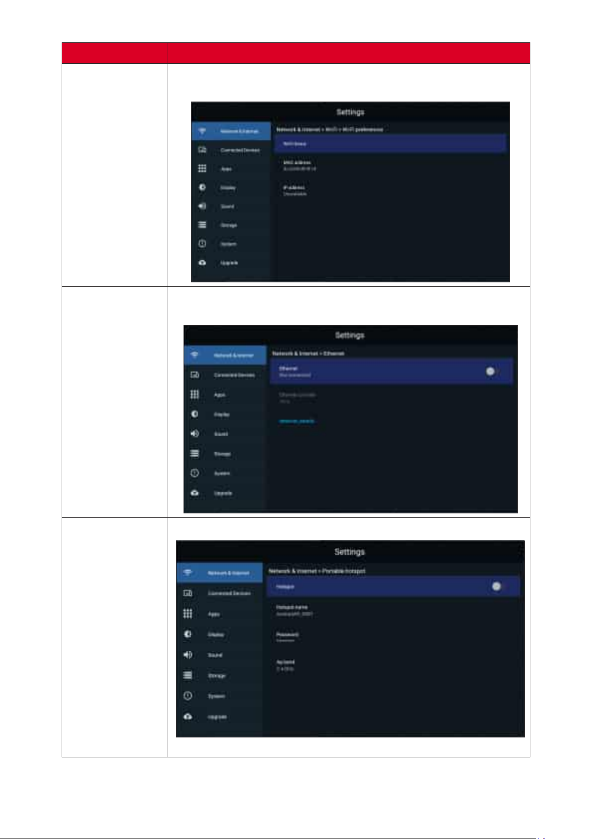
Sub-menu
Select Wi-Fi Preferences to view Wi-Fi usage preferences, Wi-Fi
connec俿on 俿ps, etc.
Wi-Fi
Select to enable/disable Ethernet, review DNS, and IP
mode.
Portable
Hotspot
Enable/disable Portable Wi-Fi Hotspot under Portable Hotspot.
43
Page 44
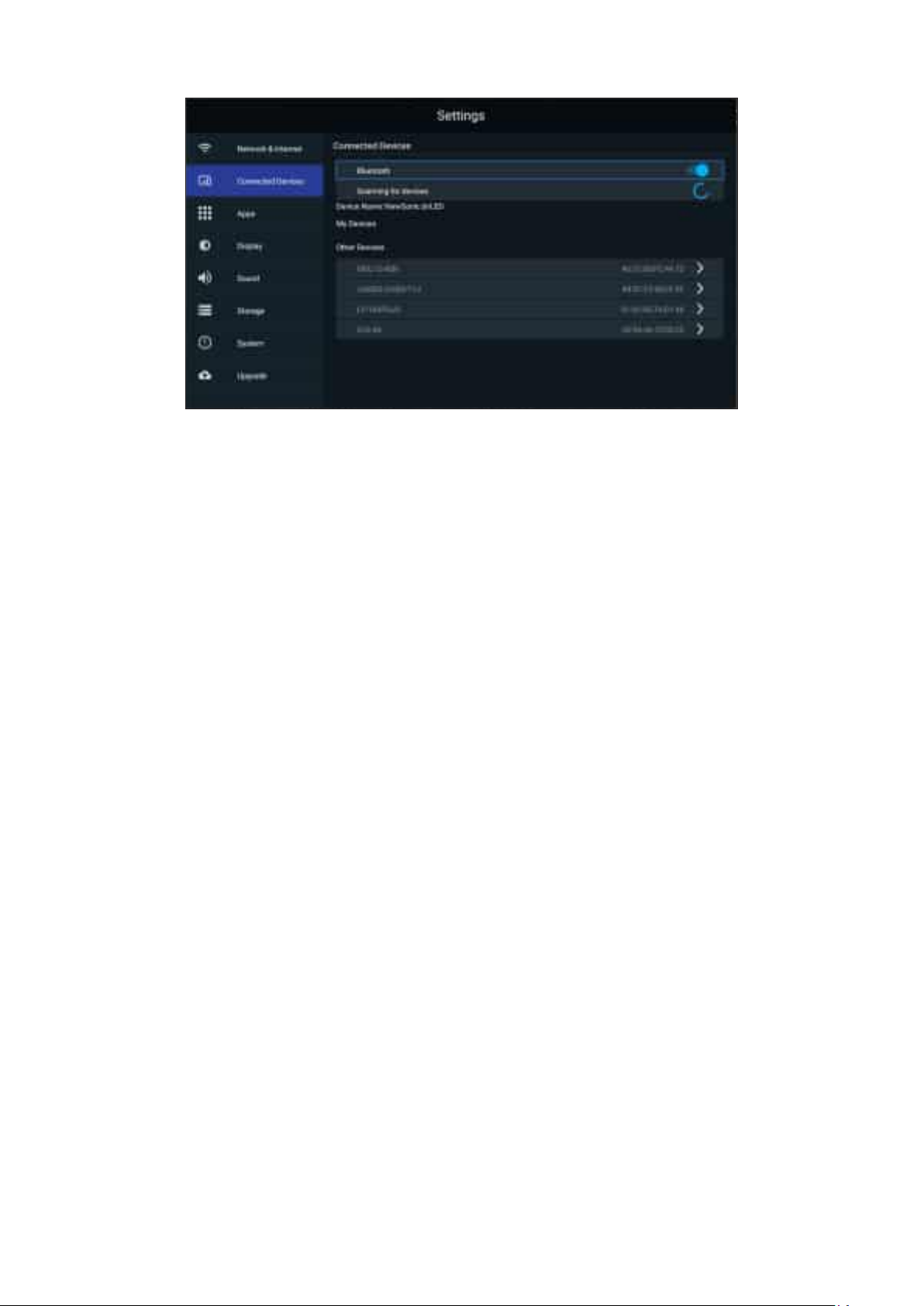
Connected Devices
Enable/disable device connec俿on, review connected devices, and search and
connect to other devices.
44
Page 45
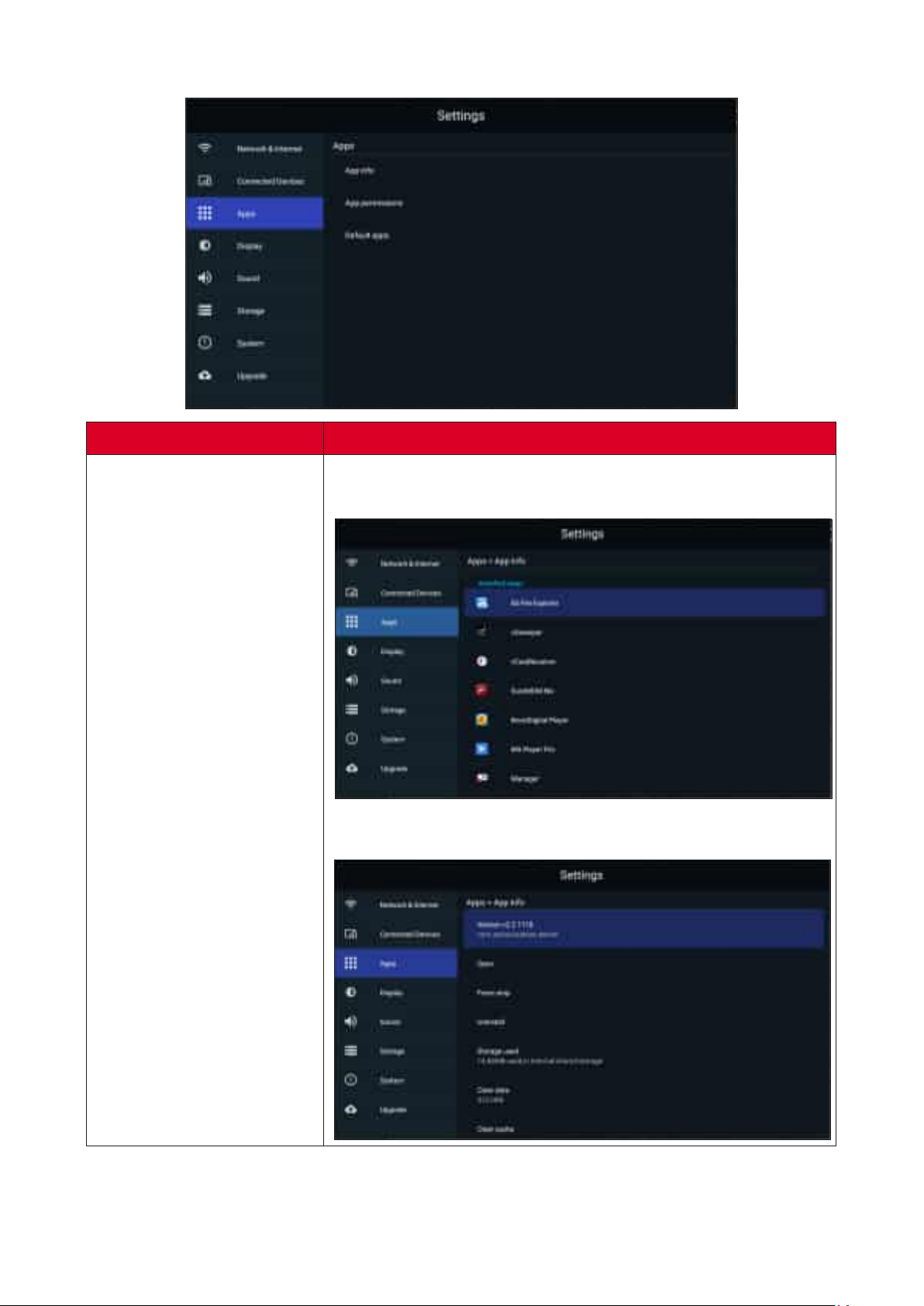
Apps
Sub-menu
Select App Info to view installed applica俿ons and their
detailed informa俿on.
App Info.
You can also disable the applica俿on, review no俿ca俿ons and
permissions, and adjust further se濿ngs.
45
Page 46
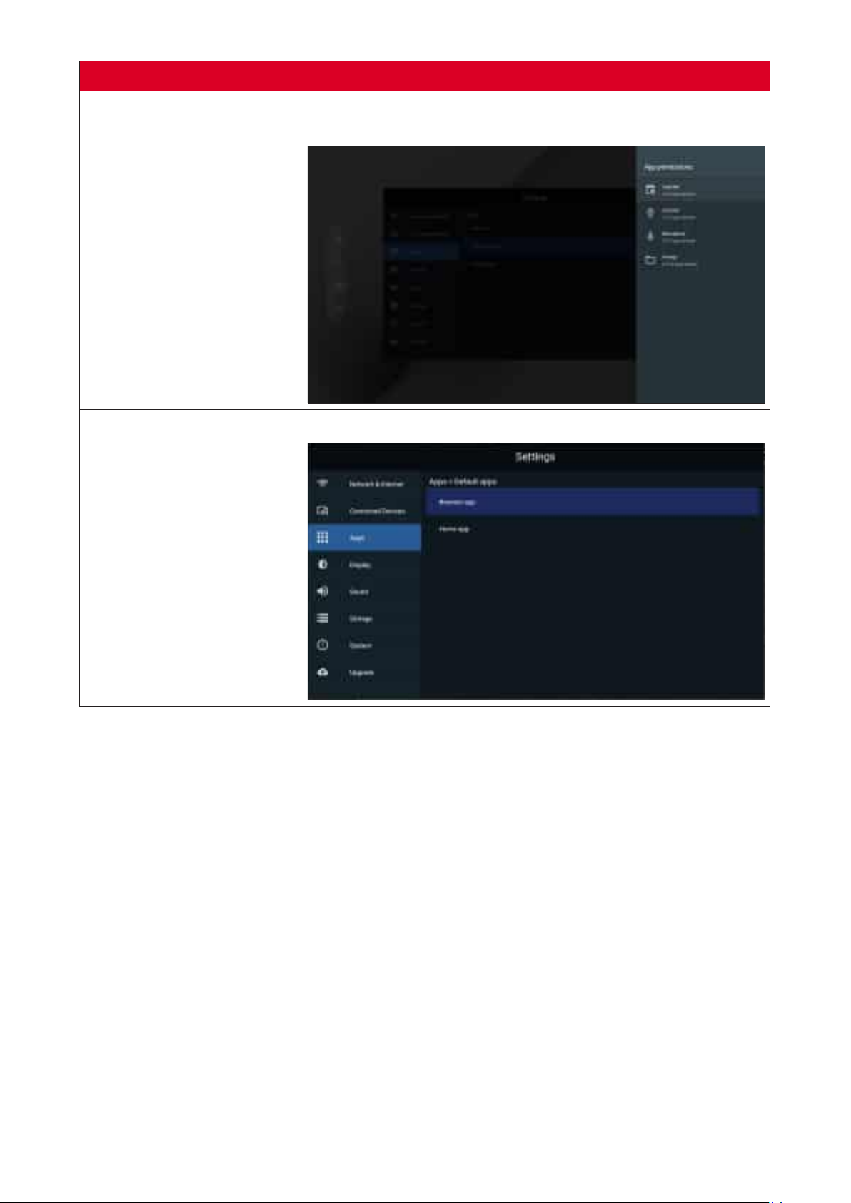
Sub-menu
Select App Permissions to manage various applica俿on
permissions.
App Permissions
Select your default applica俿ons.
Default Apps
46
Page 47
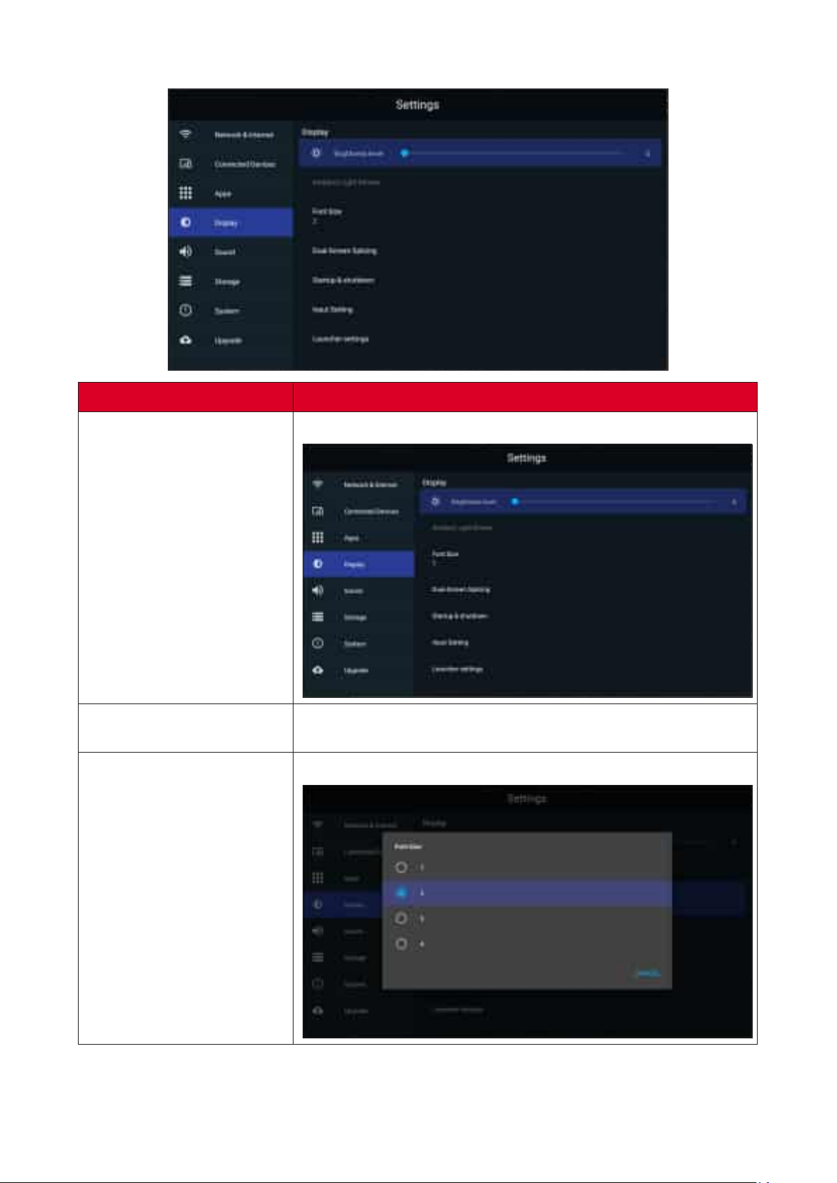
Display
Sub-menu
Adjust the brightness level by eight (8) levels.
Font Size
Detects ambient light and adjusts brightness levels
automa俿cally.
Preview and adjust the font size on the display.
47
Page 48
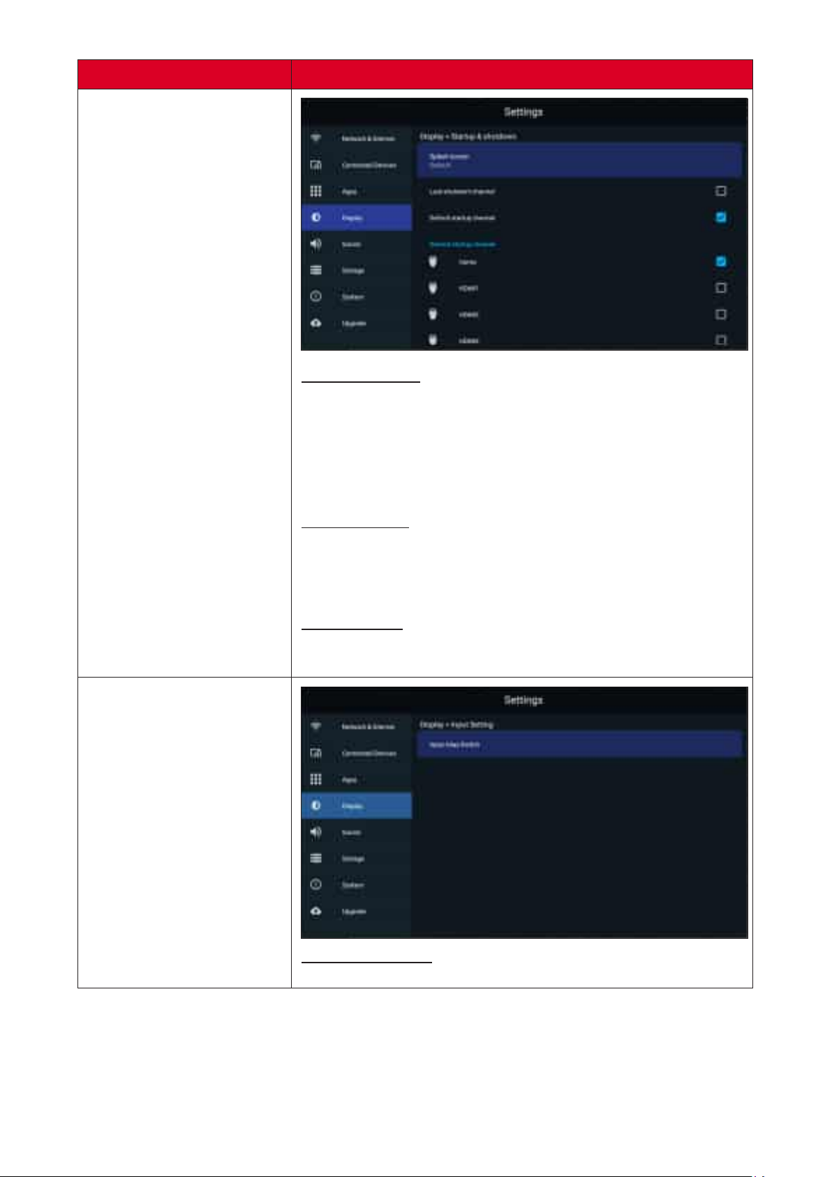
Sub-menu
Startup & Shutdown
Startup Channel
Start in the channel that was last
used before the previous shutdown.
Select a specic startup
channel (Home, HDMI 1/2/3/4/5/6, USB C, APP(Display),
APP(vCastReceiver)).
Standby Mode
Power o� the screen only.
Power down the display to minimal power
consump俿on (0.5W).
Splash Screen
Change the boot screen to black, blue, or the ViewSonic
logo.
Input Alias Switch
Display or hide the input source.
48
Page 49
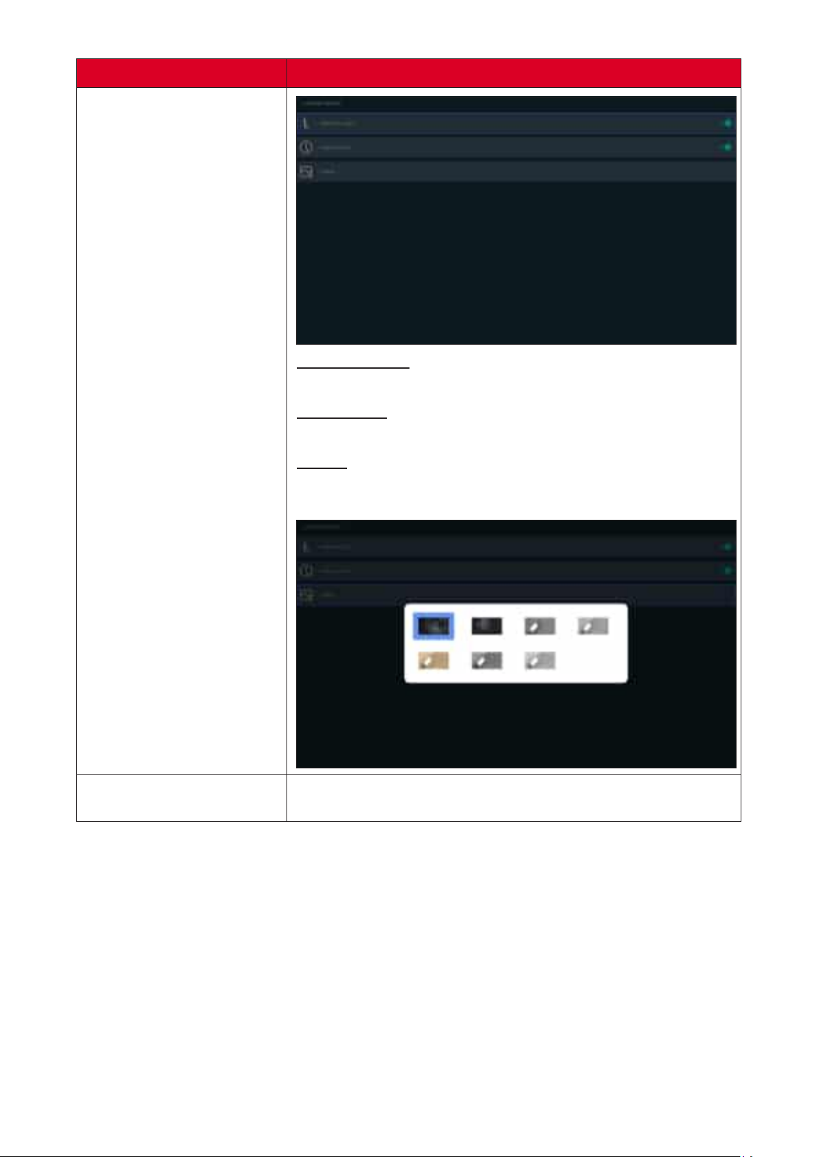
Sub-menu
ViewSonic Logo
Display or hide the ViewSoinc logo on the Home Screen.
Date & Time
Display or hide the date and 俿me on the Home Screen.
Theme
Choose from seven (7) included themes for the Home
Screen.
Adjust the Resolu俿on, DPI, wallpaper and other display
se濿ngs.
49
Page 50
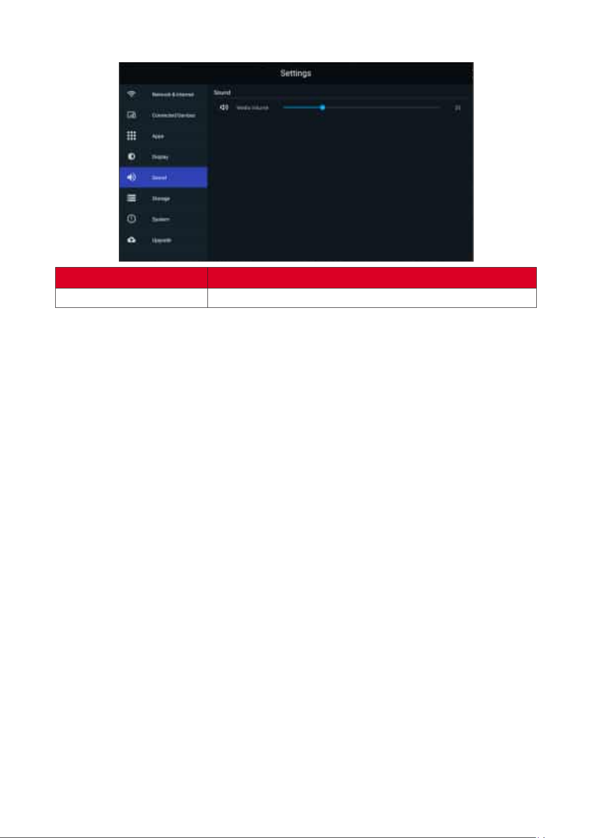
Sound
Sub-menu
Media Volume
Adjust the volume level of the display.
50
Page 51
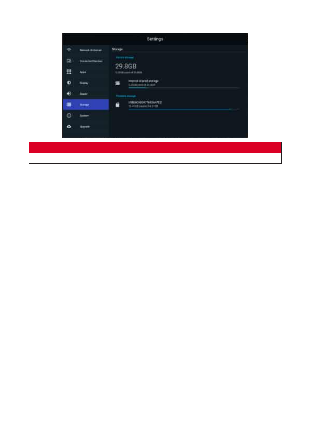
Storage
Sub-menu
Internal Shared Storage
Internal storage alloca俿on.
51
Page 52
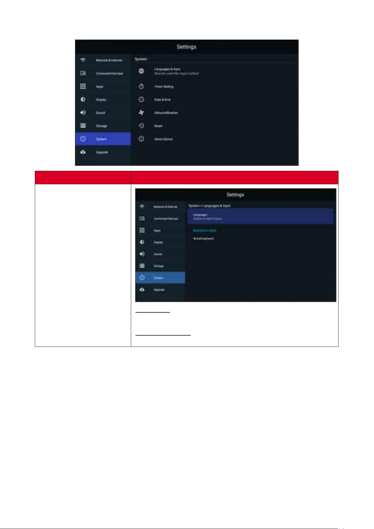
System
Sub-menu
Languages
Language selec俿on.
Virtual Keyboard
Select your input method.
52
Page 53
Sub-menu
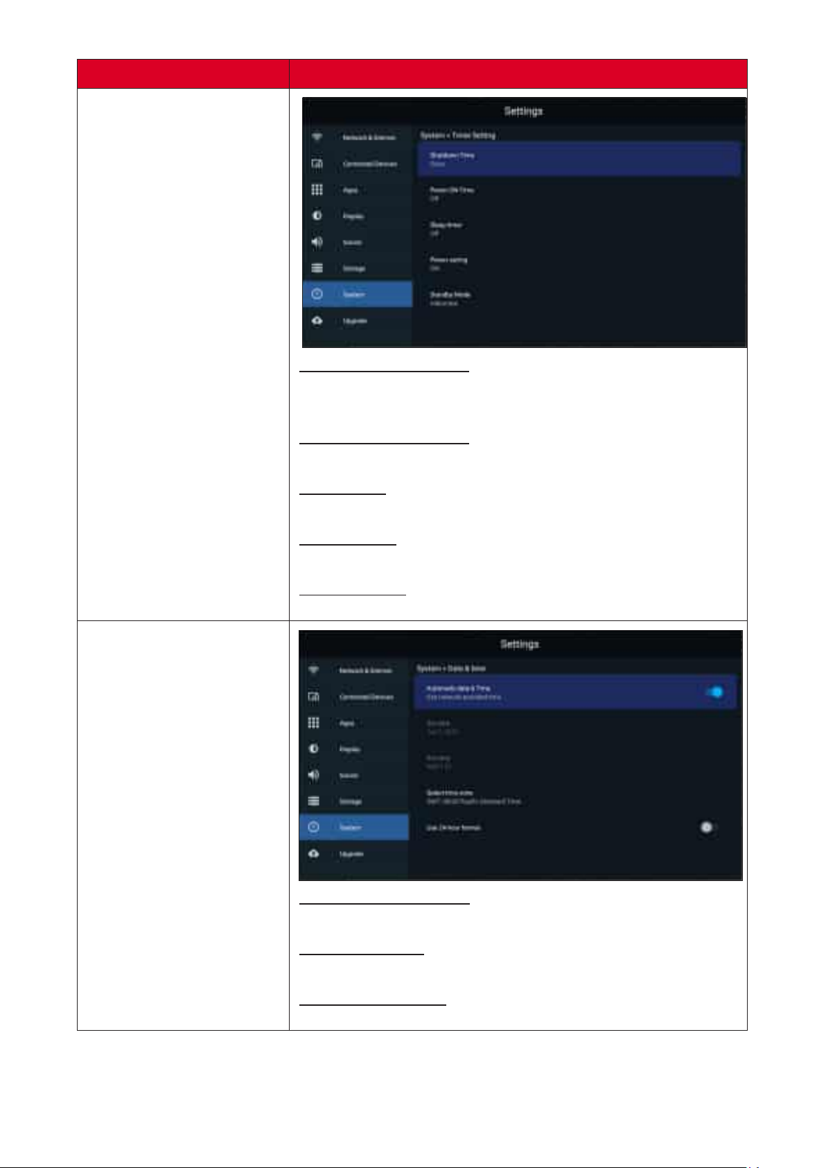
Shutdown Time Repeat
Select the 俿me and frequency for shu濿ng down the
display.
Power ON Time Repeat
Select the 俿me and frequency for powering ON the display.
Sleep Timer
Set the amount of 俿me before entering sleep mode.
Power Saving
Select when to enable power saving mode.
Standby Mode
Choose between Hibernate and Sleep modes.
Date & Time
Automa俿c Date & Time
Enable or disable automa俿c 俿me adjustment.
Select Time Zone
Choose your appropriate 俿me zone.
Use 24-hour Format
Enable or disable 24-hour 俿me format.
53
Page 54
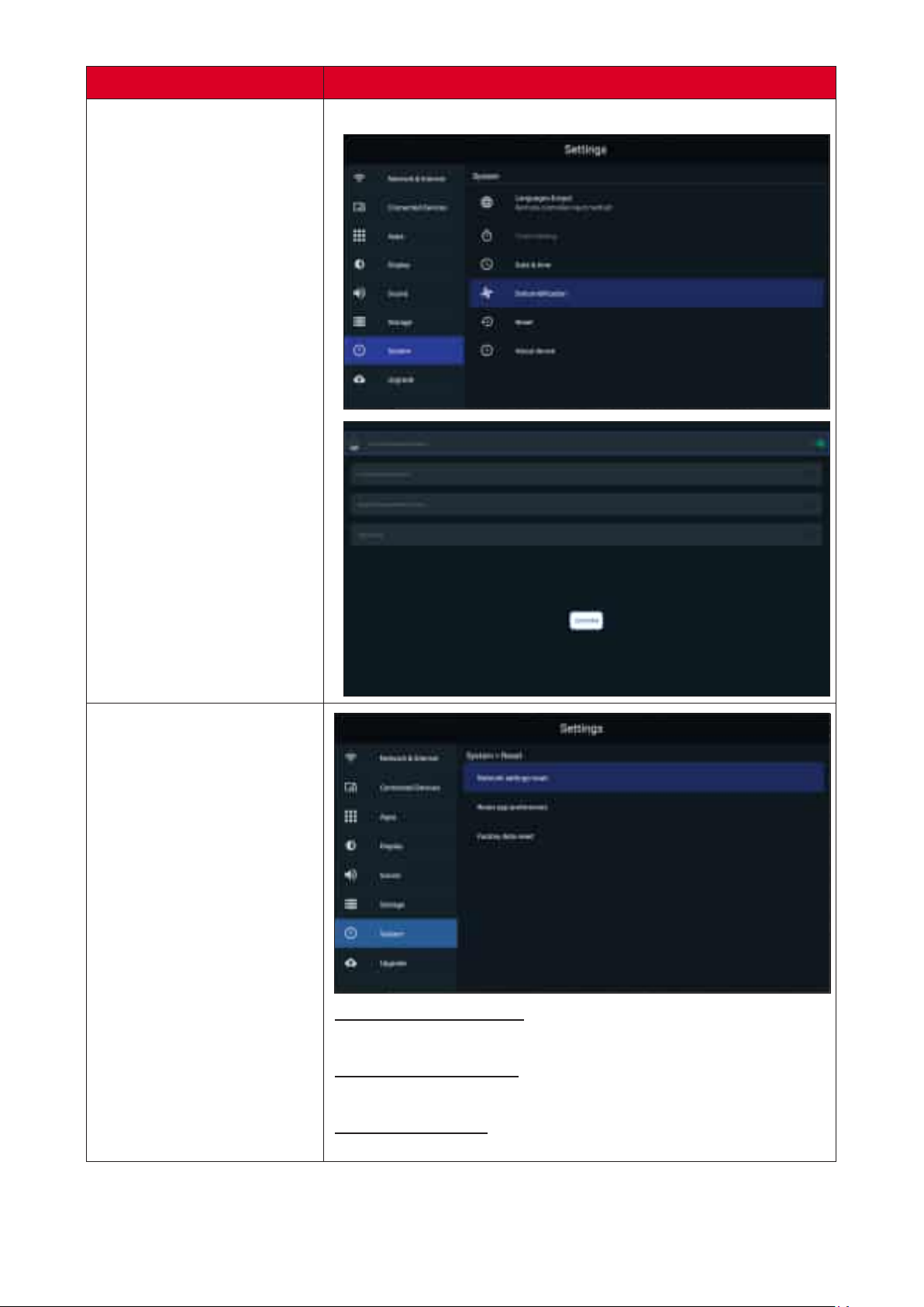
Sub-menu
Start and adjust dehumidica俿on se濿ngs.
Reset
Network Se濿ngs Reset
Reset current network se濿ngs.
Reset App Preferences
Reset current app preferences.
Factory Data Reset
Restore the display to default factory se濿ngs.
54
Page 55
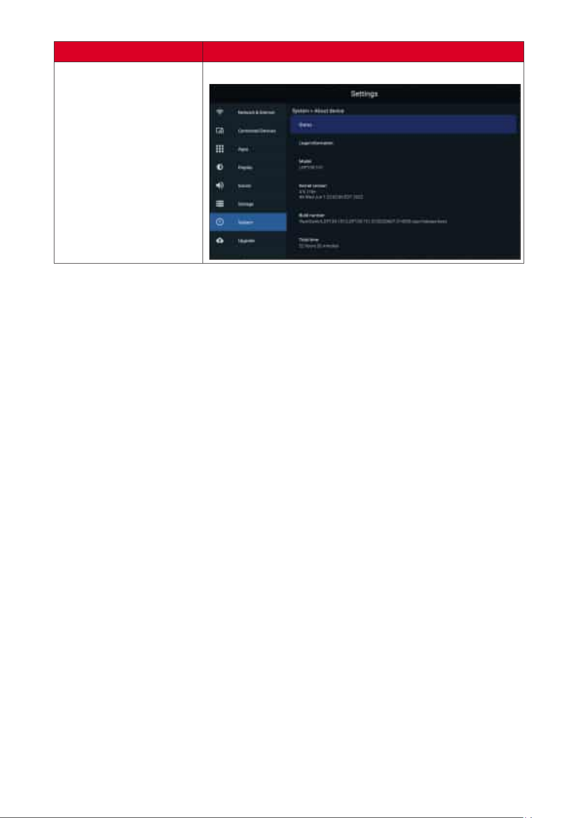
Sub-menu
View informa俿on about the display.
About Device
55
Page 56
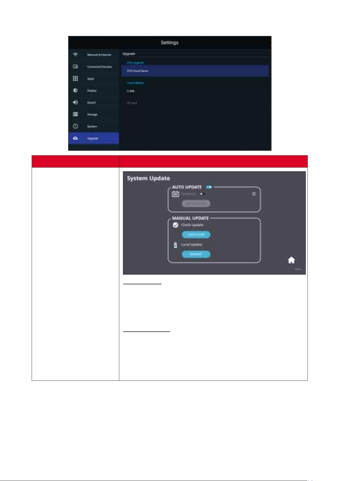
Upgrade
Sub-menu
OTA Upgrade
Auto Update
Automa俿cally apply updates as they become available or
schedule the default update date and choose “Hibernate”
as the Standby Mode, and the system will automa俿cally
update the schedule a㿿er shutdown.
Manual Update
The system will check for the latest FW
automa俿cally. If a new FW version is found, conrm the
new FW is needed and then manually run the update.
Plug in a USB drive with the FW update in
.zip format and run the .zip le to update the FW.
56
Page 57
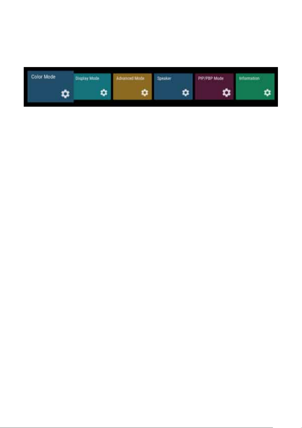
On-Screen Display (OSD) Menu
Use the On-Screen Display (OSD) Menu to adjust se濿ngs.
The OSD Menu is only available when there is an ac俿ve input source, e.g.
HDMI.
To open and operate the OSD Menu:
1. Press the bu忿on on the remote control.
2. Press q/p/t/u on the remote control to select menu items or adjust values.
3. Press OK to conrm your selec俿on.
4. Press the bu忿on to go back to the previous menu level.
5. Press the bu忿on to exit the OSD Menu.
57
Page 58
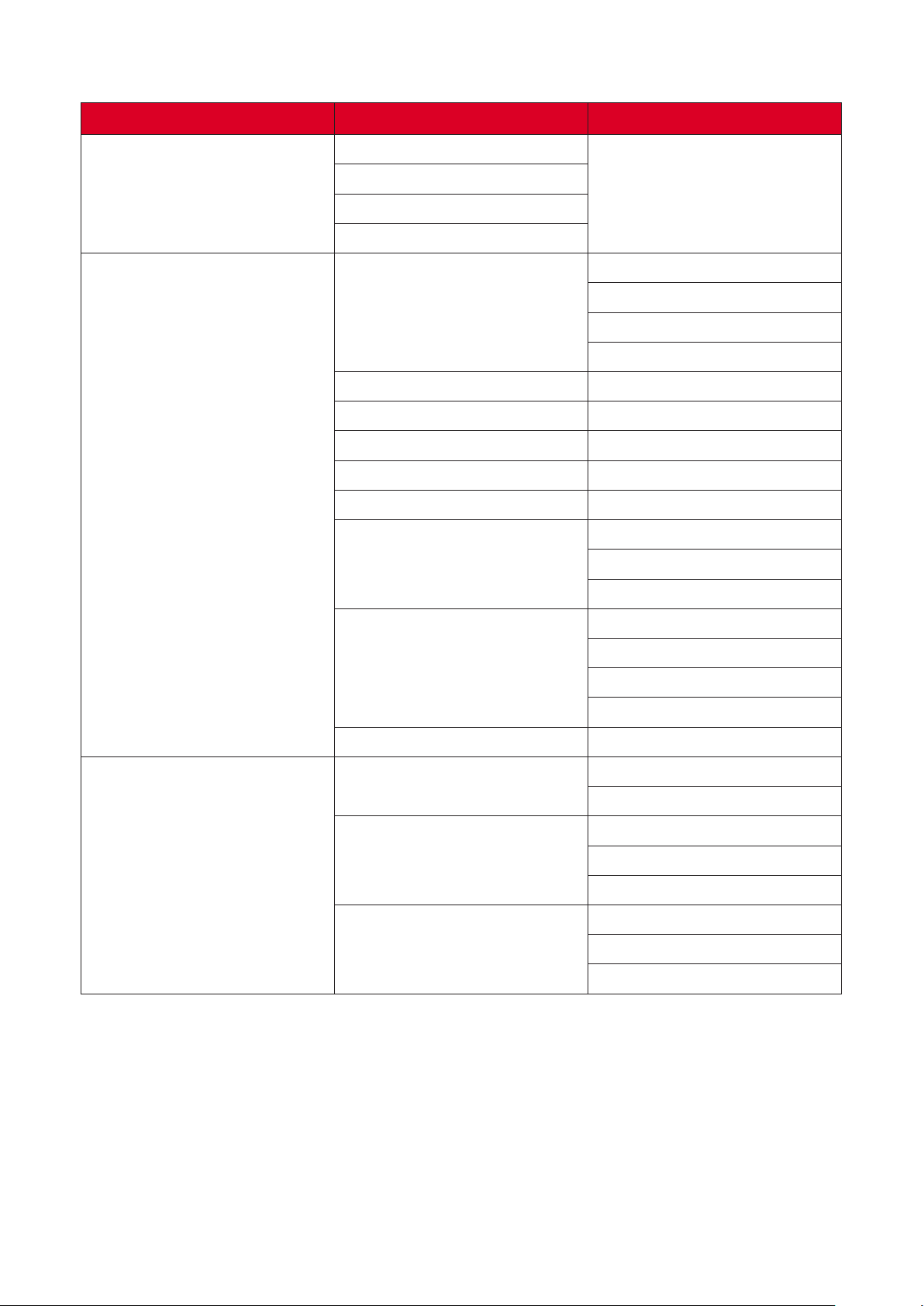
On-Screen Display (OSD) Menu Tree
Main Menu Sub-menu
User
Color Mode
Display Mode
TV
Movie
Presenta俿on
Auto
Aspect Ra俿o
Brightness (-/+, 0~100)
Contrast (-/+, 0~100)
Tint (-/+, -50~50)
Satura俿on (-/+, 0~100)
Sharpness (-/+, 0~20)
Gamma
4:3
16:9
Na俿ve
Dark
Middle
Bright
User
Advanced Mode
Color Temp
Reset
HDR
EOTF
HDMI Se濿ng
Standard
Cool
Warm
Auto
SDR
Dark
Middle
Bright
Auto
Full
Limited
58
Page 59
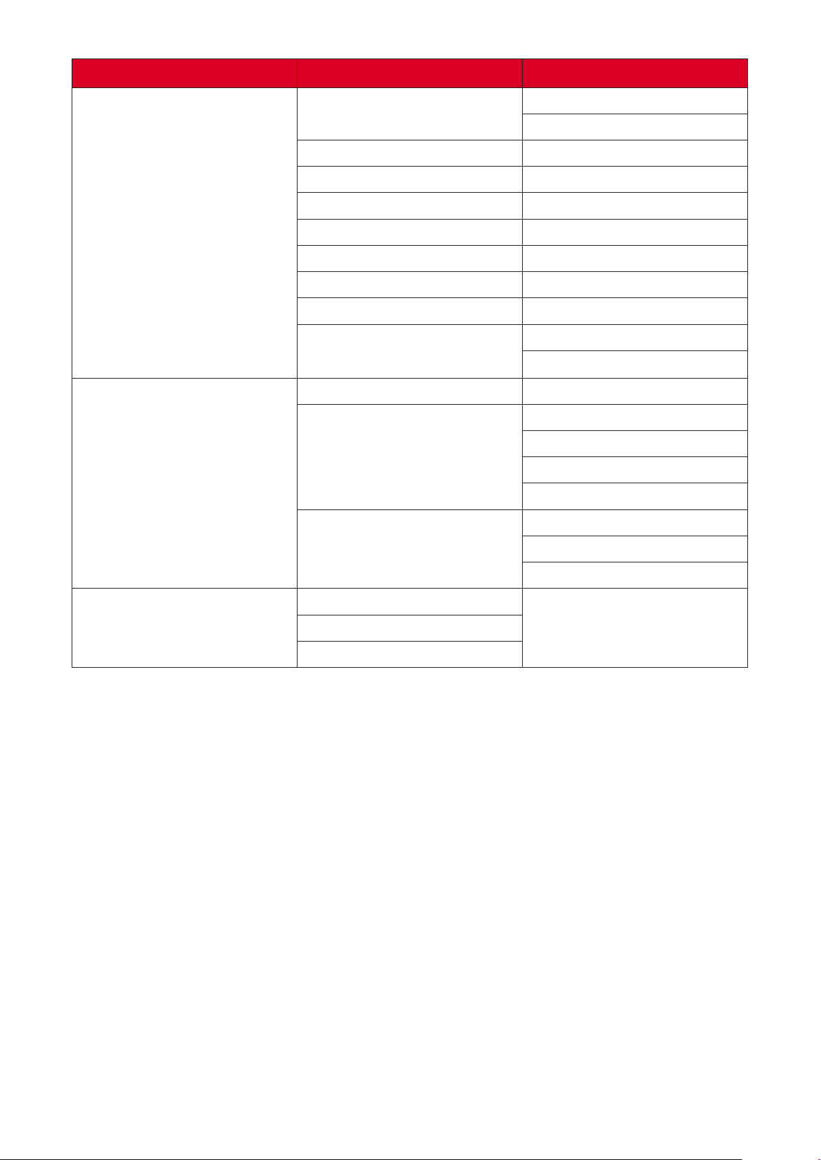
Main Menu Sub-menu
Speaker
PIP/PBP Mode
Audio Mode
Movie
Music
EQ_120Hz (-/+, 0~100)
EQ_500Hz (-/+, 0~100)
EQ_1.5KHz (-/+, 0~100)
EQ_5KHz (-/+, 0~100)
EQ_10KHz (-/+, 0~100)
Reset
Audio Volume (-/+, -50~50)
On
Mute
O�
O�
Sub Picture on Top Le㿿
Sub Picture on Top Right
PIP
Sub Picture on Bo忿om Le㿿
Sub Picture on Bo忿om Right
PBP
Source
Resolu俿on
HDR
Windows x 2
Windows x 3
Windows x 4
59
Page 60
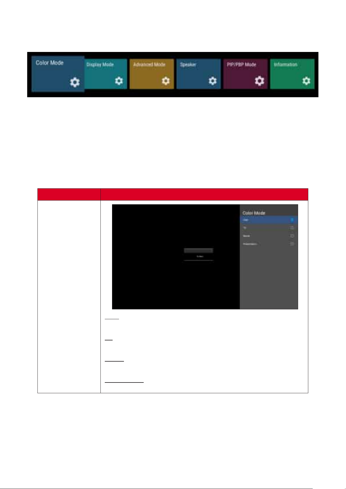
Color Mode
1. Press on the remote control to display the OSD Menu.
2. Then press OK or use q/p/t/u on the remote control to select the Color Mode
menu.
3. Press q/p to select the menu op俿on. Then press OK to display its sub-menu, or
press t/u to adjust/select the se濿ng.
Some sub-menu op俿ons may have another sub-menu layer.
Color Mode
User
Custom user se濿ng.
TV
Set the color temperature to 9300K.
Movie
Set the color temperature to 6500K.
Presenta俿on
Set the color temperature to 7500K.
60
Page 61
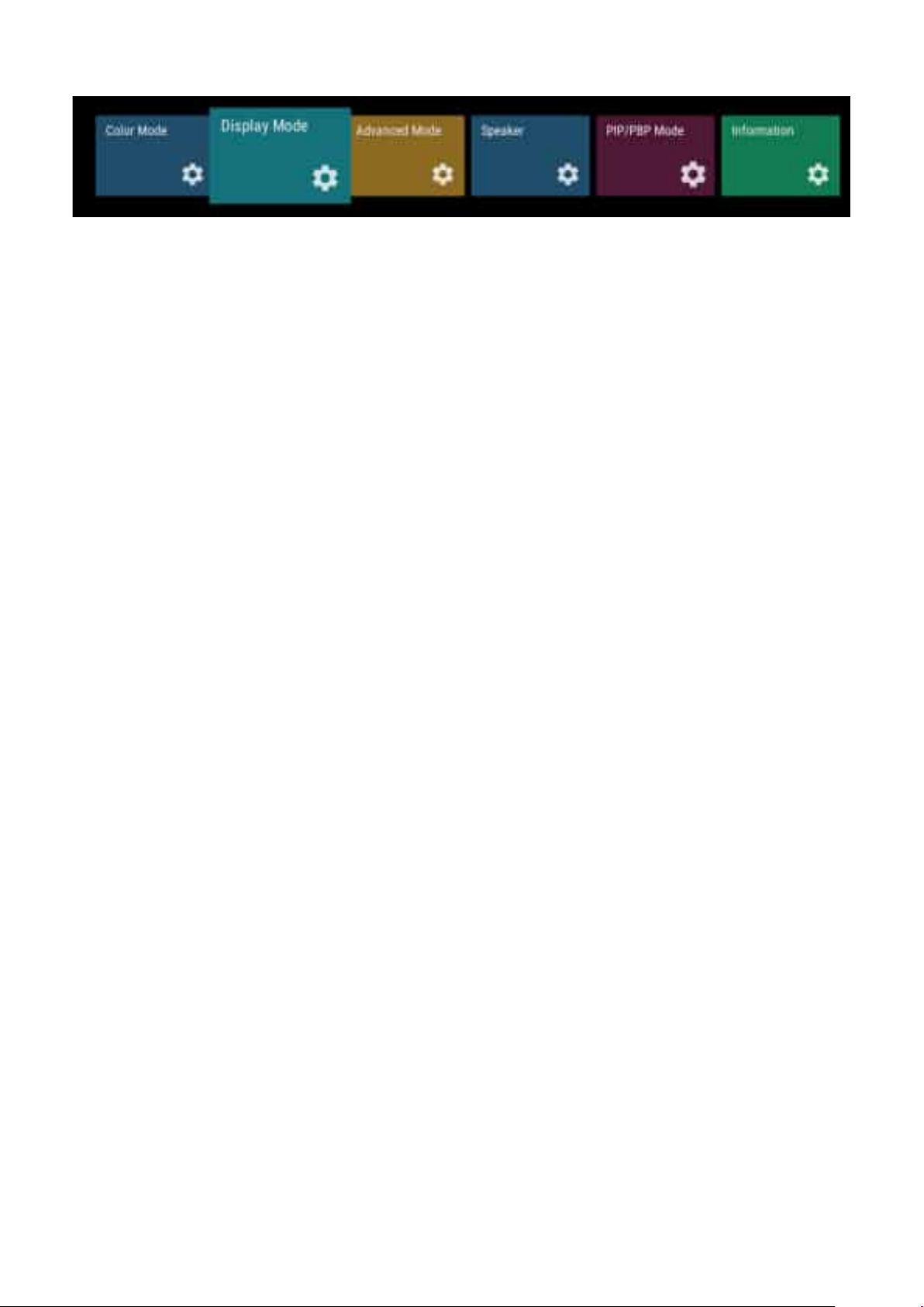
Display Mode
1. Press on the remote control to display the OSD Menu.
2. Then press OK or use q/p/t/u on the remote control to select the Display
Mode menu.
3. Press q/p to select the menu op俿on. Then press OK to display its sub-menu, or
press t/u to adjust/select the se濿ng.
Some sub-menu op俿ons may have another sub-menu layer.
61
Page 62
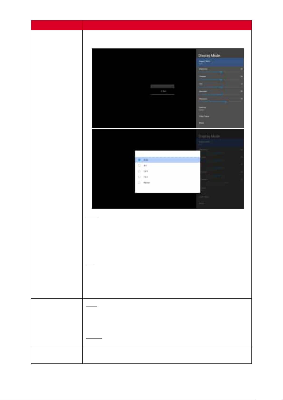
The is the ra俿o of the image width to the image
height.
Auto
Scales an image propor俿onally to t the projector’s na俿ve
resolu俿on in its horizontal width. This is suitable for the
incoming image which is neither 4:3 nor 16:9 and you want to
make the most use of the screen without altering the image’s
aspect ra俿o.
4:3
Scales an image so that it is displayed in the center of the screen
with a 4:3 aspect ra俿o. This is most suitable for 4:3 images like
computer monitors, standard deni俿on TV, and 4:3 aspect DVD
movies, as it displays them without aspect altera俿on.
Brightness
16:9
Scales an image so that it is displayed in the center of the screen
with a 16:9 aspect ra俿o. This is most suitable for images which
are already in a 16:9 aspect, like high deni俿on TV.
Na俿ve
Default aspect ra俿o.
The higher the value, the brighter the image. Lower values will
result in a darker image.
62
Page 63
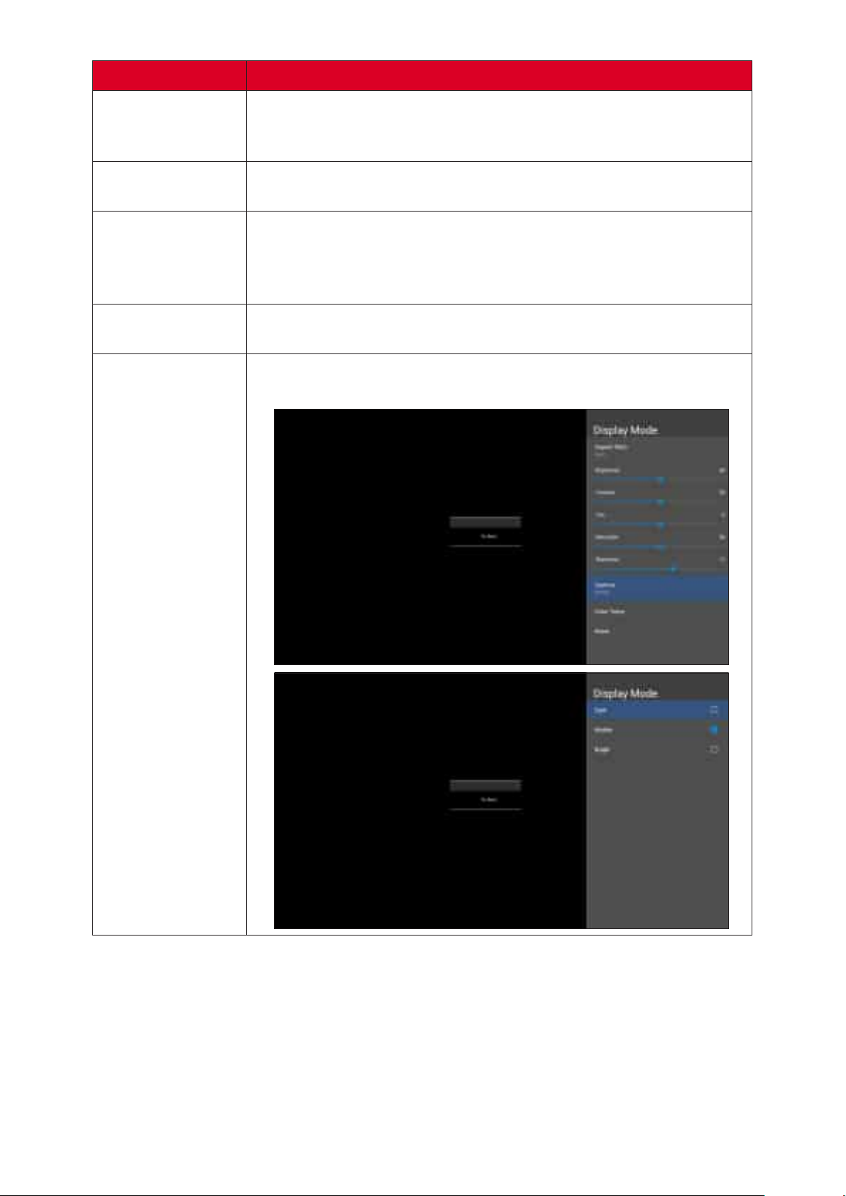
Use this to set the peak white level a㿿er you have previously
Contrast
adjusted the Brightness se濿ng to suit your selected input and
viewing environment.
Tint
Sharpness
The higher the value, the more greenish the picture becomes.
The lower the value, the more reddish the picture becomes.
Refers to the amount of that color in a video picture. Lower
se濿ngs produce less saturated colors; in fact, a se濿ng of “0”
removes that color from the image en俿rely. If the satura俿on is
too high, that color will be overpowering and unrealis俿c.
A high value results in a sharper picture; a low value so㿿ens the
picture.
Manually adjust the brightness level of the monitor’s grayscale
levels.
Gamma
63
Page 64
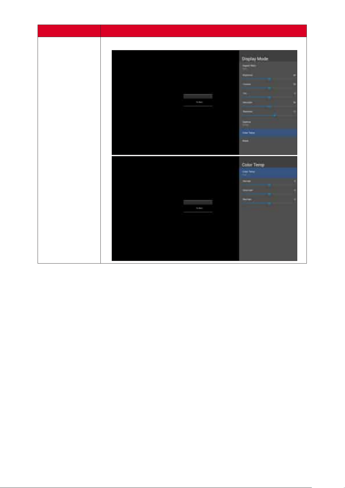
Manually adjust the red, green, and blue values.
Color Temp
64
Page 65
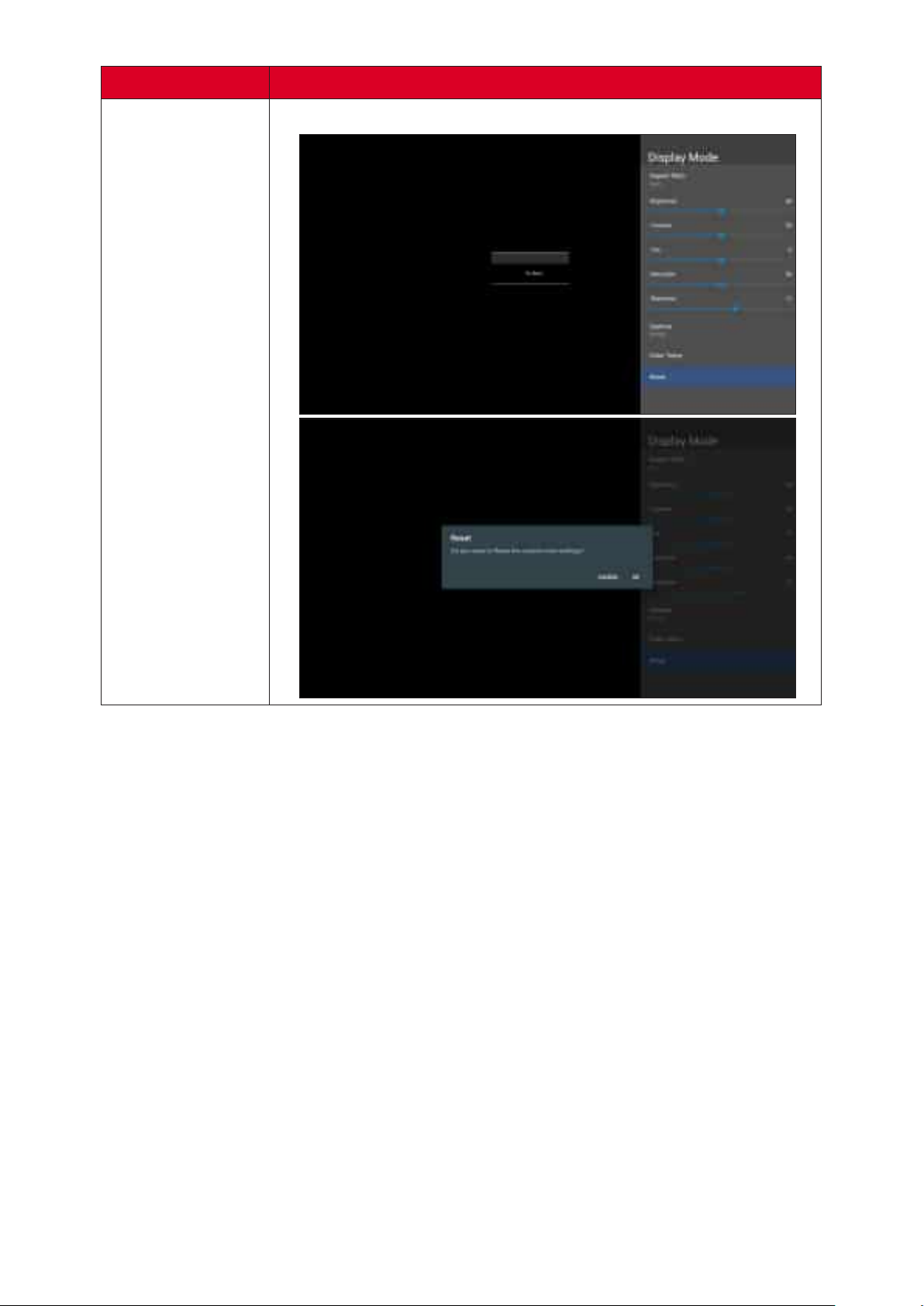
Return the Display Mode se濿ngs to their default values.
Reset
65
Page 66
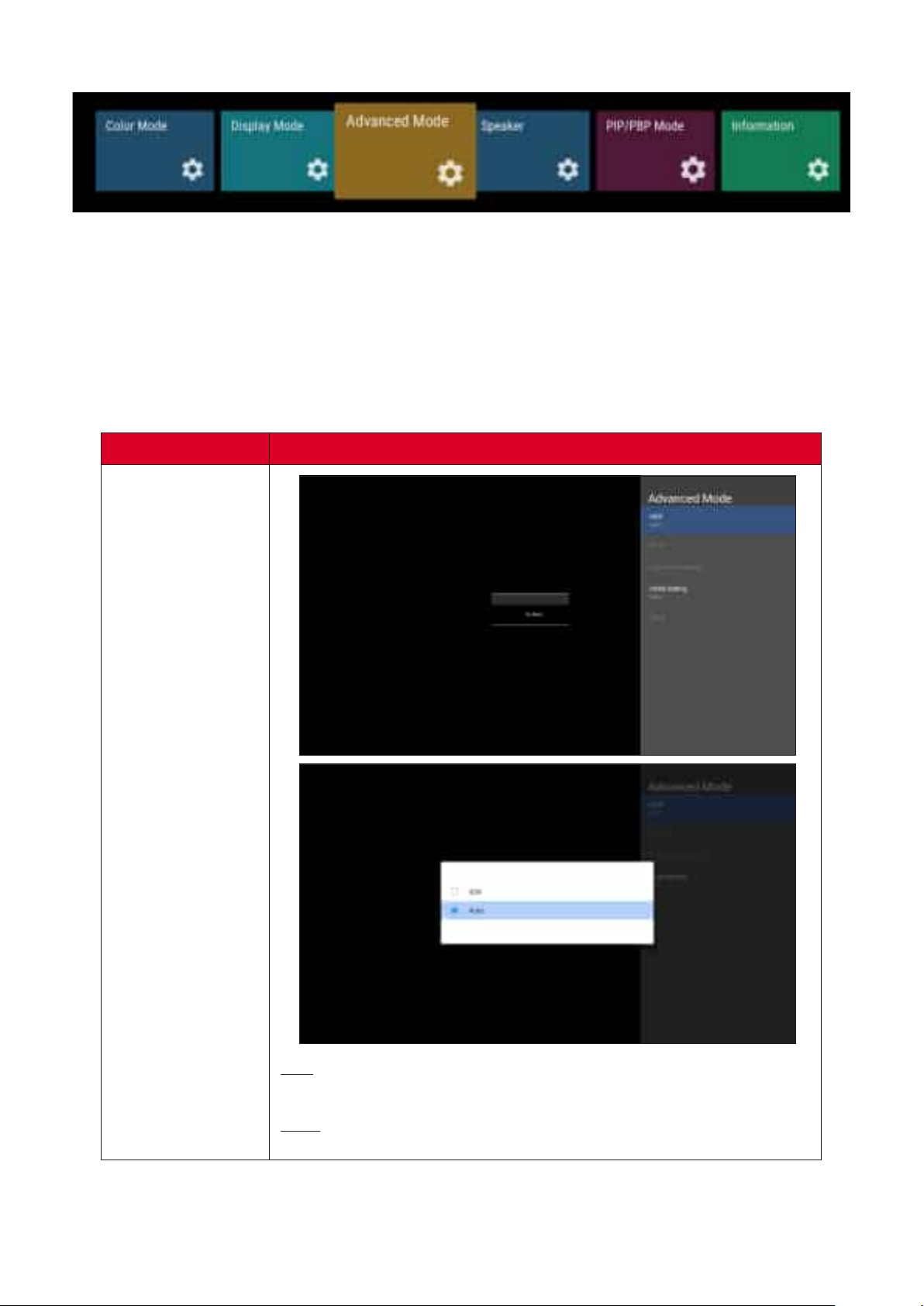
Advanced Mode
1. Press on the remote control to display the OSD Menu.
2. Then press OK or use q/p/t/u on the remote control to select the Advanced
Mode menu.
3. Press q/p to select the menu op俿on. Then press OK to display its sub-menu, or
press t/u to adjust/select the se濿ng.
Some sub-menu op俿ons may have another sub-menu layer.
HDR
SDR
Enable Standard Dynamic Range.
Auto
Automa俿cally adjust to the input source.
66
Page 67
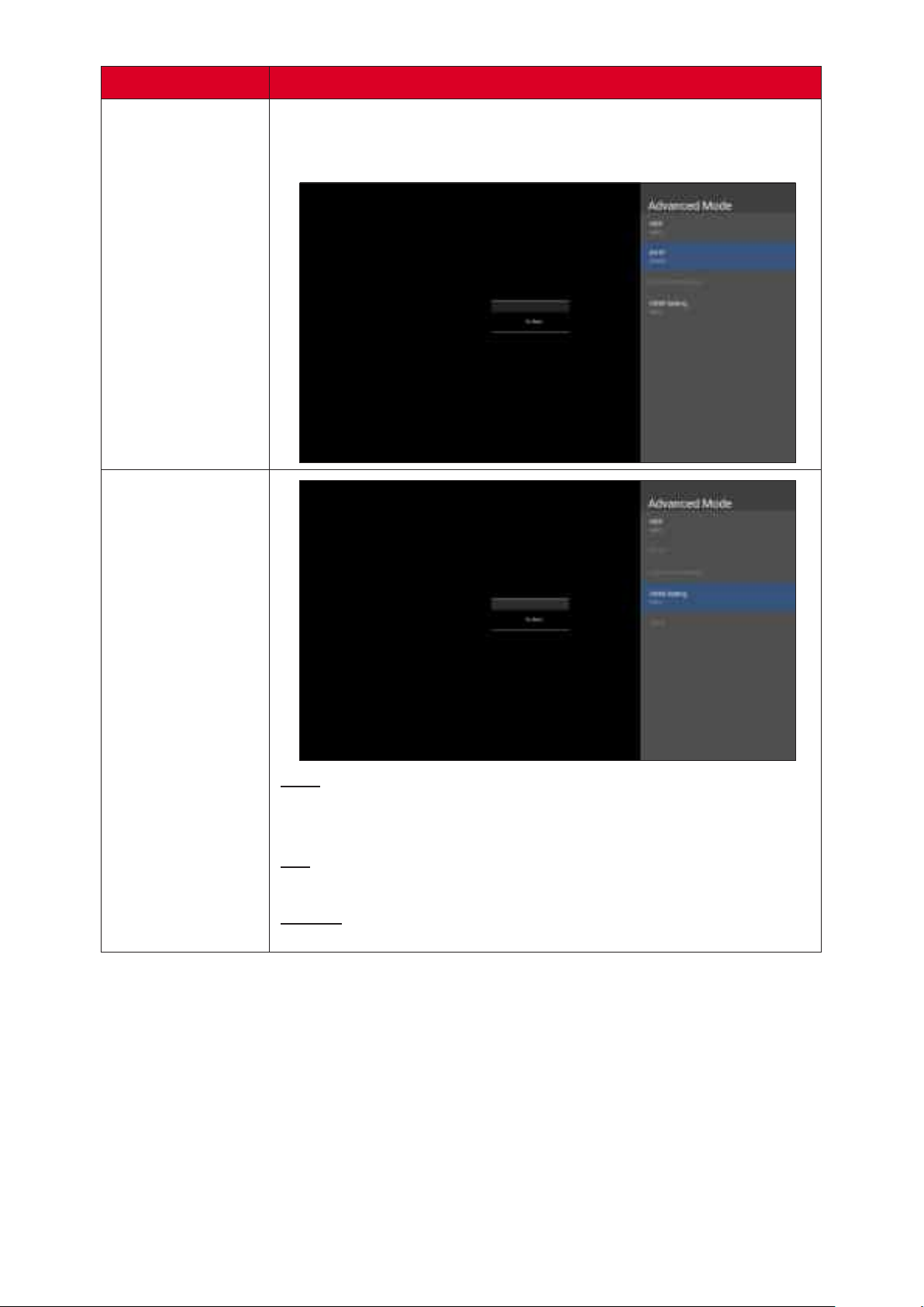
Automa俿cally adjusts the brightness levels of your image
according to the input source. You can also manually select a
brightness level to display be忿er picture quality.
Auto
Sets the display to detect the range of the input signal
automa俿cally.
Full
Sets the color range from 0~255.
Limited
Sets the color range from 15~255.
67
Page 68
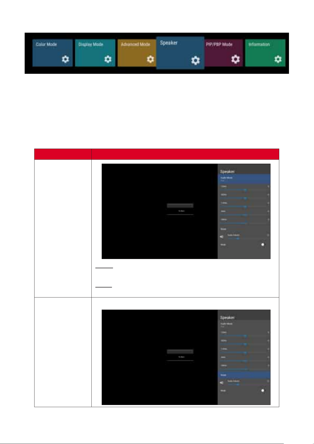
Speaker
1. Press on the remote control to display the OSD Menu.
2. Then press OK or use q/p/t/u on the remote control to select the Speaker
menu.
3. Press q/p to select the menu op俿on. Then press OK to display its sub-menu, or
press t/u to adjust/select the se濿ng.
Some sub-menu op俿ons may have another sub-menu layer.
Audio Mode
Reset
Movie
Enhance the sense of space.
Music
Vibrant treble and stronger bass.
Return the Speaker se濿ngs to their default values.
68
Page 69
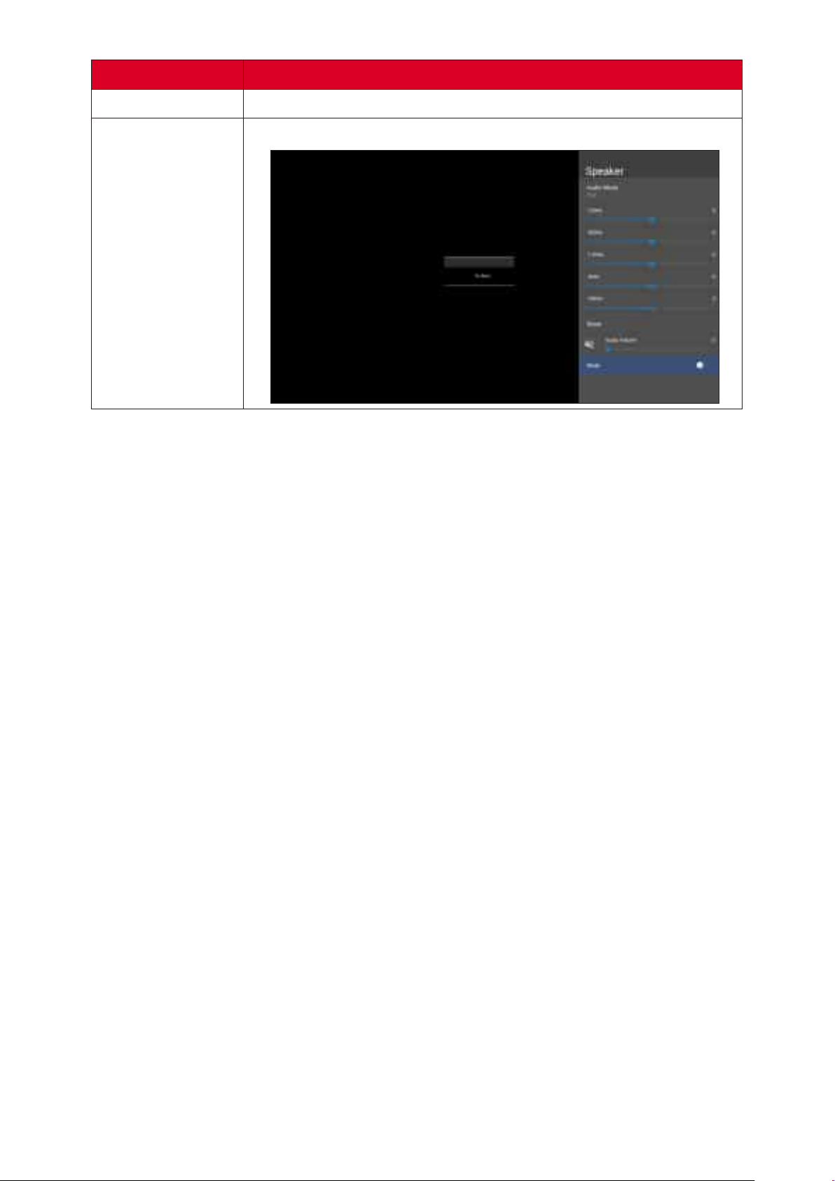
Audio Volume
Mute
Adjust the volume level.
Toggle On to turn o� the speaker.
69
Page 70
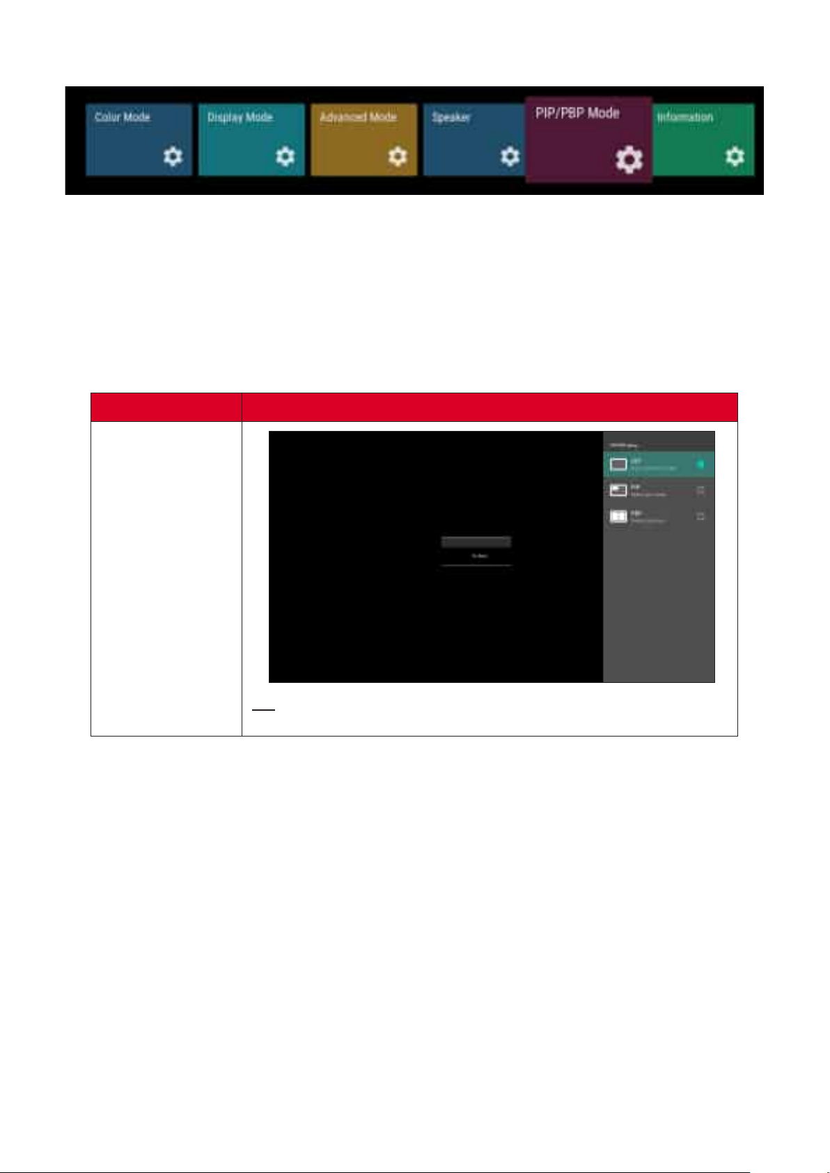
PIP/PBP Mode
1. Press on the remote control to display the OSD Menu.
2. Then press OK or use q/p/t/u on the remote control to select the PIP/PBP
Mode menu.
3. Press q/p to select the menu op俿on. Then press OK to display its sub-menu, or
press t/u to adjust/select the se濿ng.
Some sub-menu op俿ons may have another sub-menu layer.
PIP/PBP Setup
O�
Disable the PIP/PBP feature.
70
Page 71
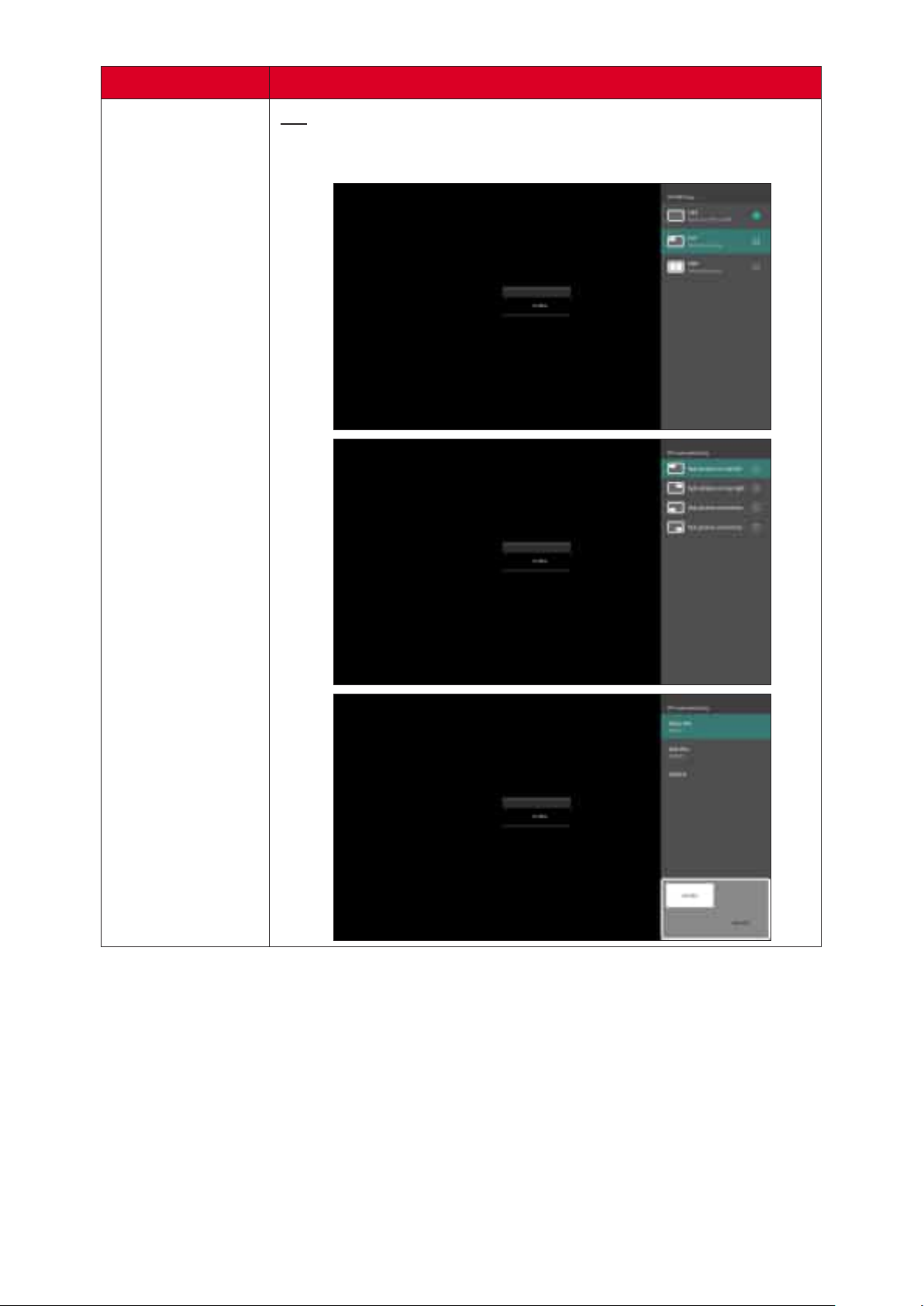
PIP
Split the screen into two parts, a main window and an inset
window. User can specify the input source for each screen.
PIP/PBP Setup
71
Page 72
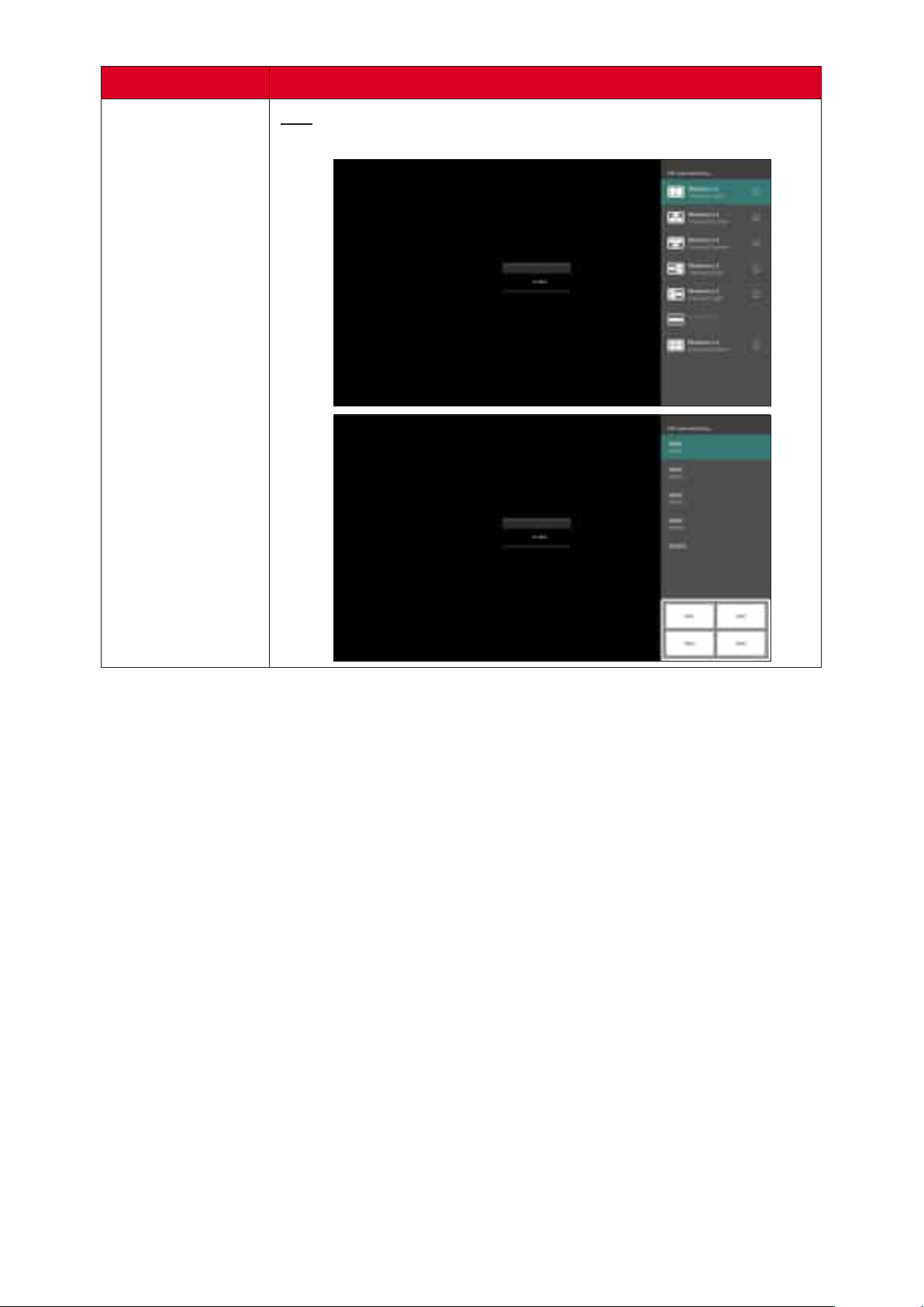
PBP
Display up to four (4) windows on screen at the same 俿me.
PIP/PBP Setup
72
Page 73
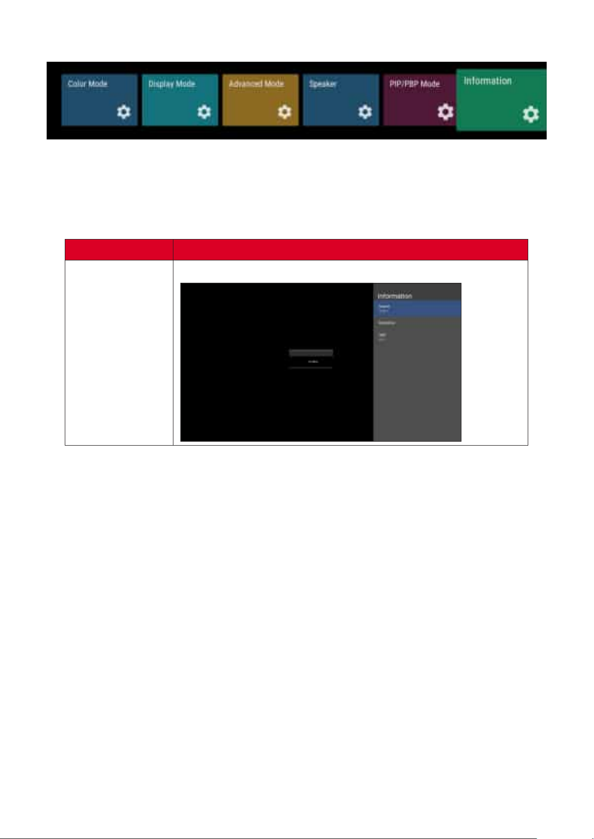
1. Press on the remote control to display the OSD Menu.
2. Then press OK or use q/p/t/u on the remote control to select the
menu.
3. Press q/p to select the menu op俿on. Then press OK to display its sub-menu.
View Input Source, Resolu俿on, and HDR informa俿on.
73
Page 74
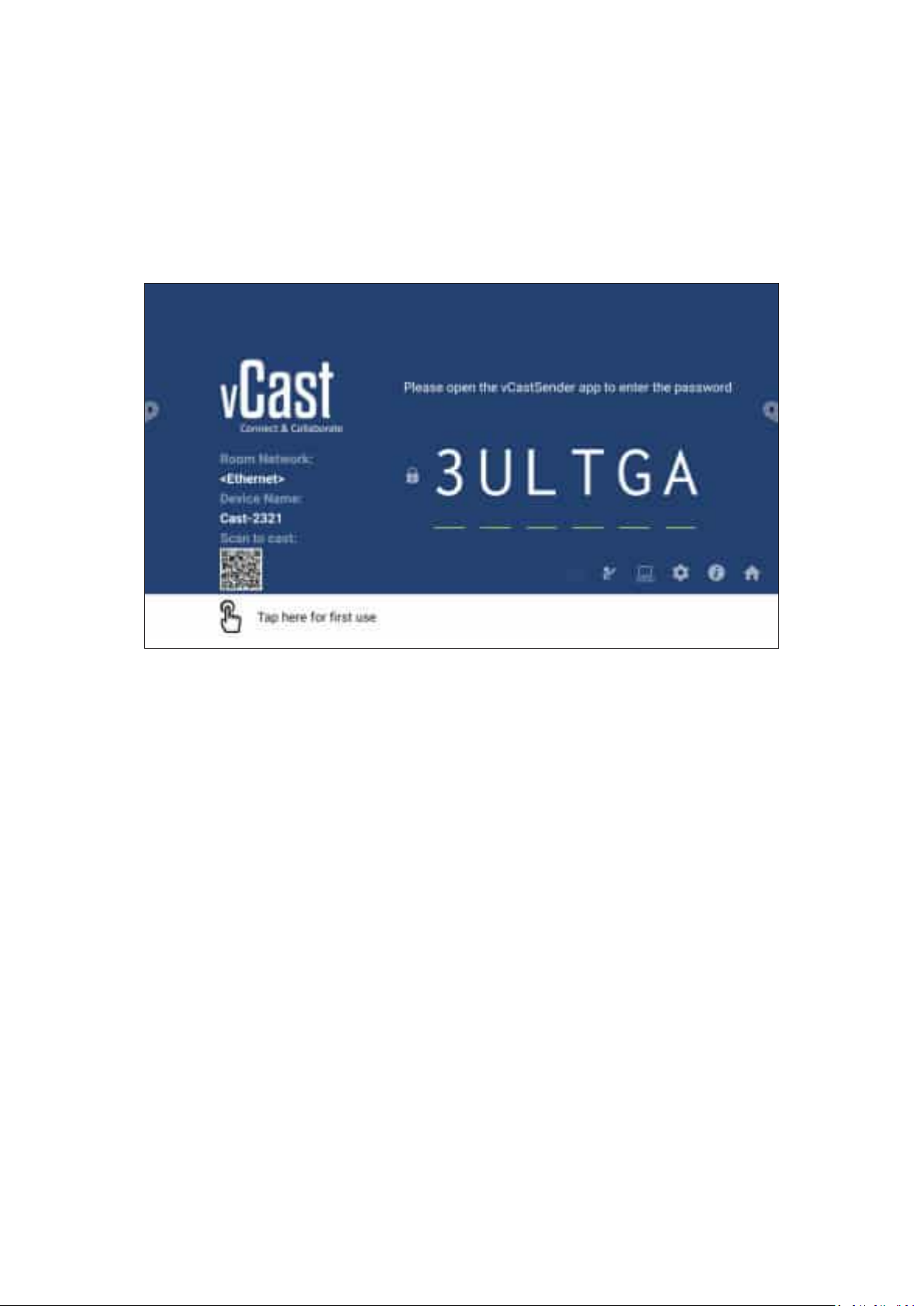
vCast
Working with ViewBoard® Cast so㿿ware (vCast, vCast Pro, and vCastSender), the
vCast applica俿on will allow the ViewBoard to receive laptop screens (Windows/
Mac/Chrome) and mobile (iOS/Android) users’ screens, photos, videos,
annota俿ons, and camera(s) that are using the vCastSender applica俿on.
74
Page 75

• ViewBoard® Cast so㿿ware, laptops, and mobile devices can connect to both the
same subnet and cross subnet by entering the on-screen PIN code.
• Connected devices will show up under Device List on the same subnet
connec俿on.
• If the device does not show up under Device List, users will need to key-in the
on-screen PIN code.
•
TCP 56789, 25123, 8121 & 8000 (Controlling message port & client device
audio transfer)
TCP 8600 (BYOM)
TCP 53000 (Request share screen)
TCP 52020 (Reverse control)
TCP 52025 (Reverse control for ViewBoard Cast Bu忿on)
TCP 52030 (Status sync)
TCP 52040 (Moderator mode)
UDP 48689, 25123 (Device searching and broadcast & client device audio
transfer)
UDP 5353 (Mul俿cast search device protocol)
• :
Port: 443
DNS: h忿ps://vcastac俿vate.viewsonic.com
•
Server Port: TCP 443
Server FQDN Name: h忿ps://vcastupdate.viewsonic.com
75
Page 76
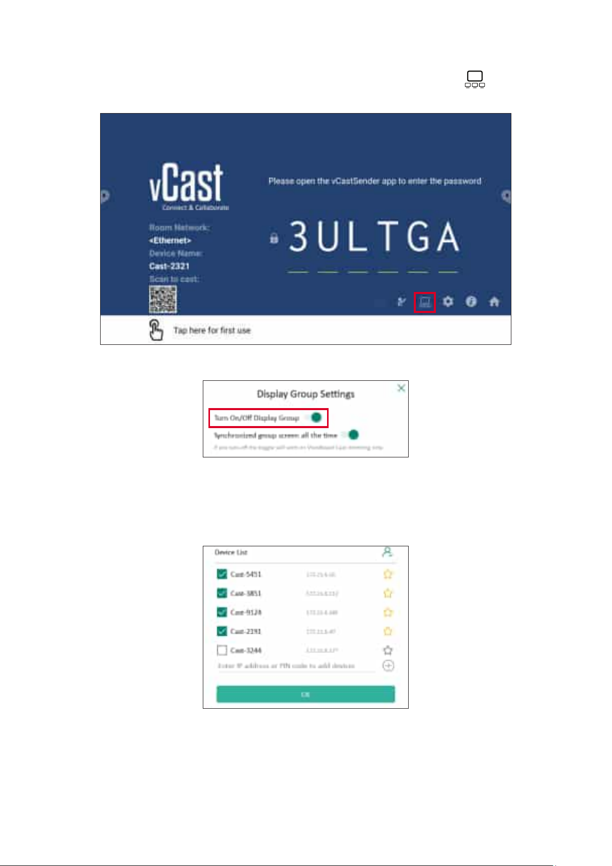
To adjust the Display Group Se濿ngs, select the Display Group icon ( ) located in
the lower-right corner of the screen.
1. Toggle the “Turn On/O� Display Group” ON to enable the Display Group feature.
Other preinstalled ViewBoard Cast devices in the same network will be
listed.
2. Select the devices you want to join the display group and select OK to save the
se濿ngs.
• If the devices you want to group are not listed, you can enter their
respec俿ve IP address or connec俿ng PIN code.
• The Display Group maximum device limit is six devices.
76
Page 77
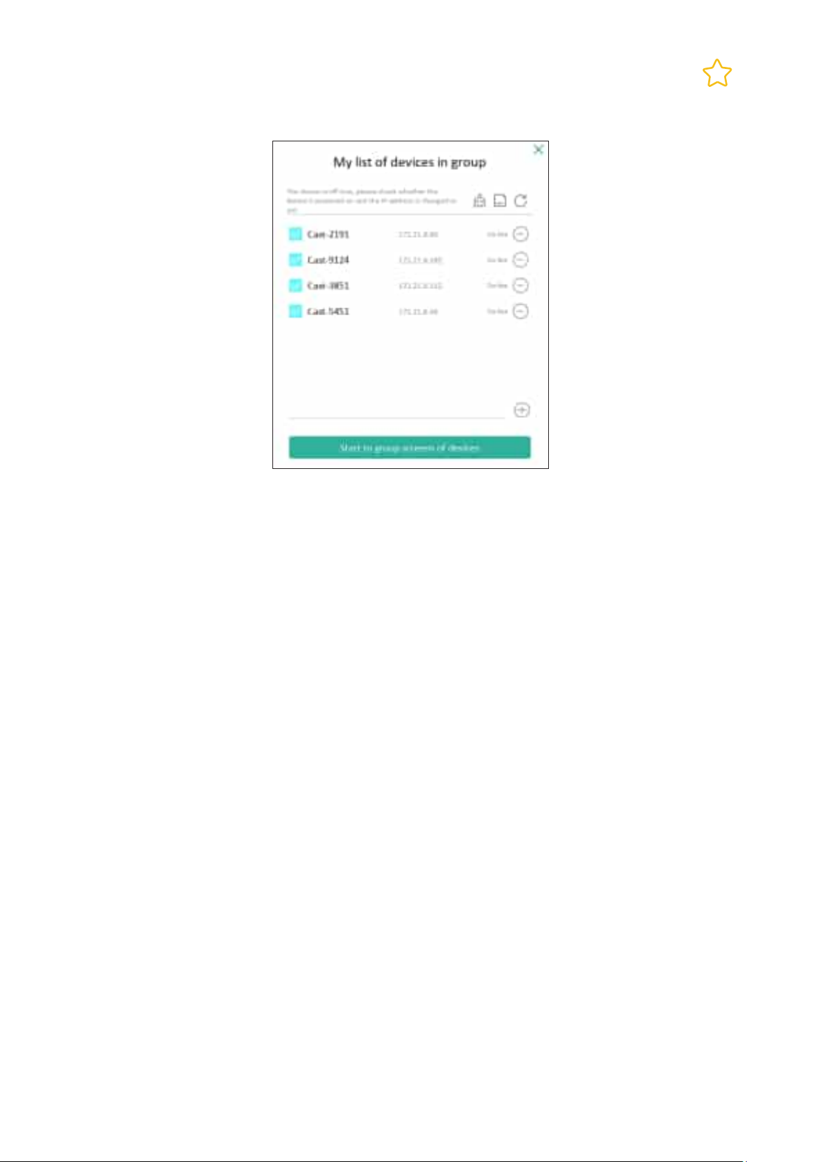
3. If you frequently connect to the same device, you can select the Star icon ( )
next to the device to add it to your frequently connected devices list, “My List of
Devices in Group”, for easier Display Group setup and management.
77
Page 78
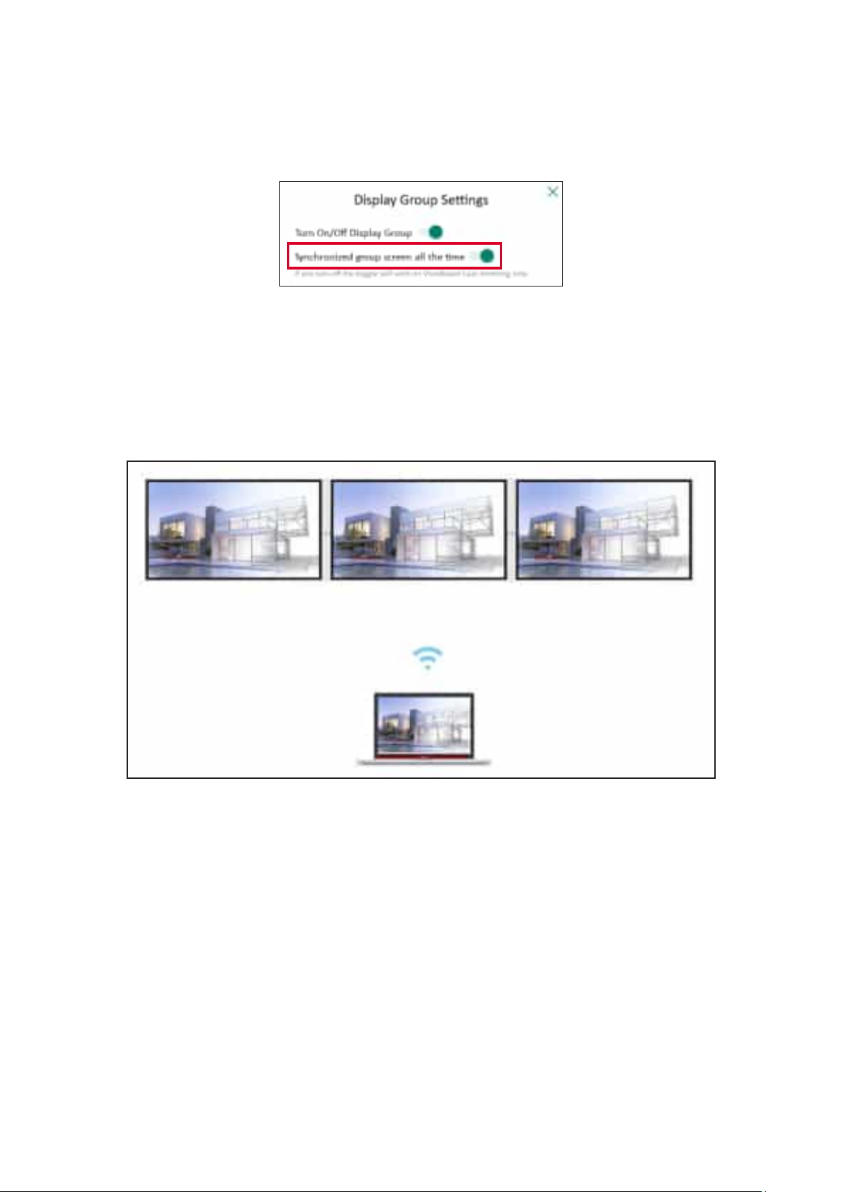
When the “Synchronized group screen all the 俿me” func俿on is toggled ON, it will
display a synchronized group screen con俿nuously. If it is toggled OFF, it will work on
vCast mirroring only.
Select the devices to group rst, then toggle the “Synchronized group
screen all the 俿me” func俿on ON to avoid interrup俿on.
A㿿er conrming the above se濿ngs, you can share your screen to the main display,
then the grouped client devices will be synced up to your screen.
78
Page 79
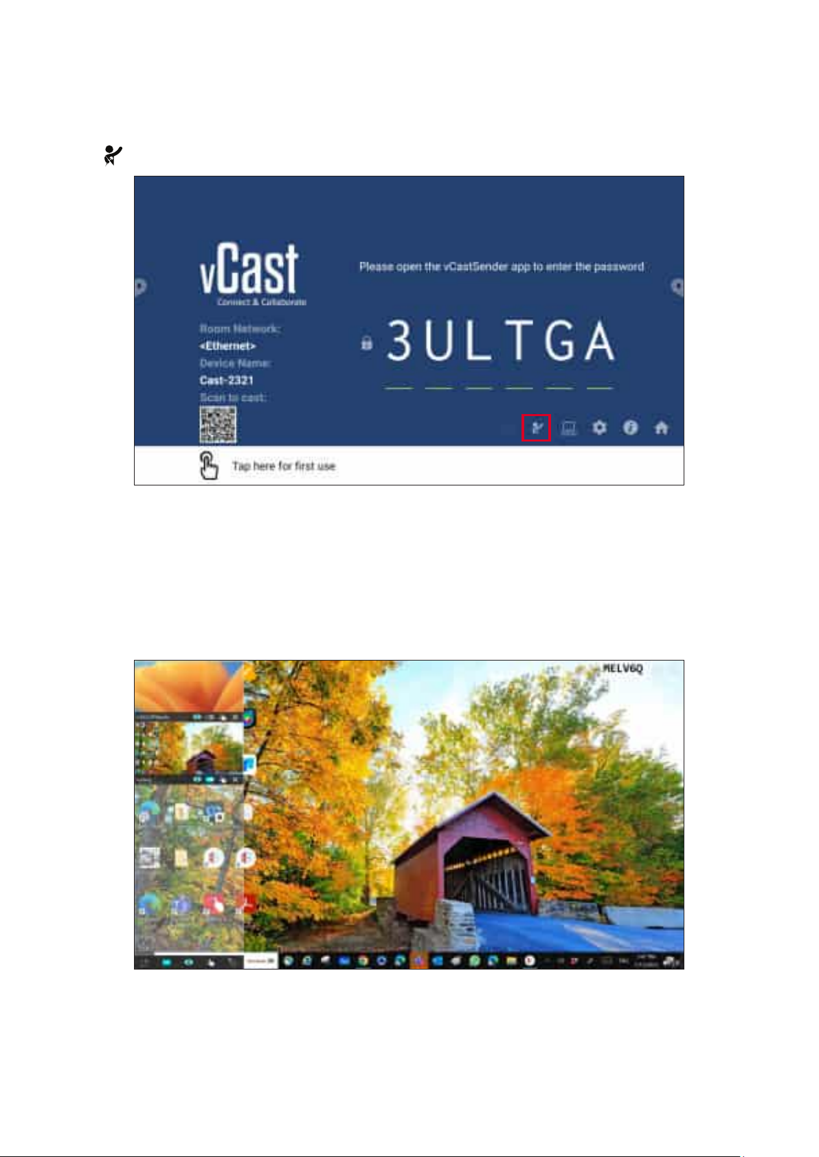
Moderator Mode allows the moderator to take control of the devices connected to
the ViewBoard or display. To enter Moderator Mode, select the Moderator Mode
icon ( ) located in the lower-right corner of the screen.
When enabled, the moderator can view a list of all connected screens in the le㿿
⿿oa俿ng window and can preview each par俿cipant’s screen and then select any
of par俿cipant’s screen and cast to the ViewBoard’s or display’s main screen for
presenta俿on. The moderator can also control each par俿cipant’s screen, annotate
on the ViewBoard or display, and remove unwanted par俿cipants by selec俿ng the
close icon (X).
79
Page 80
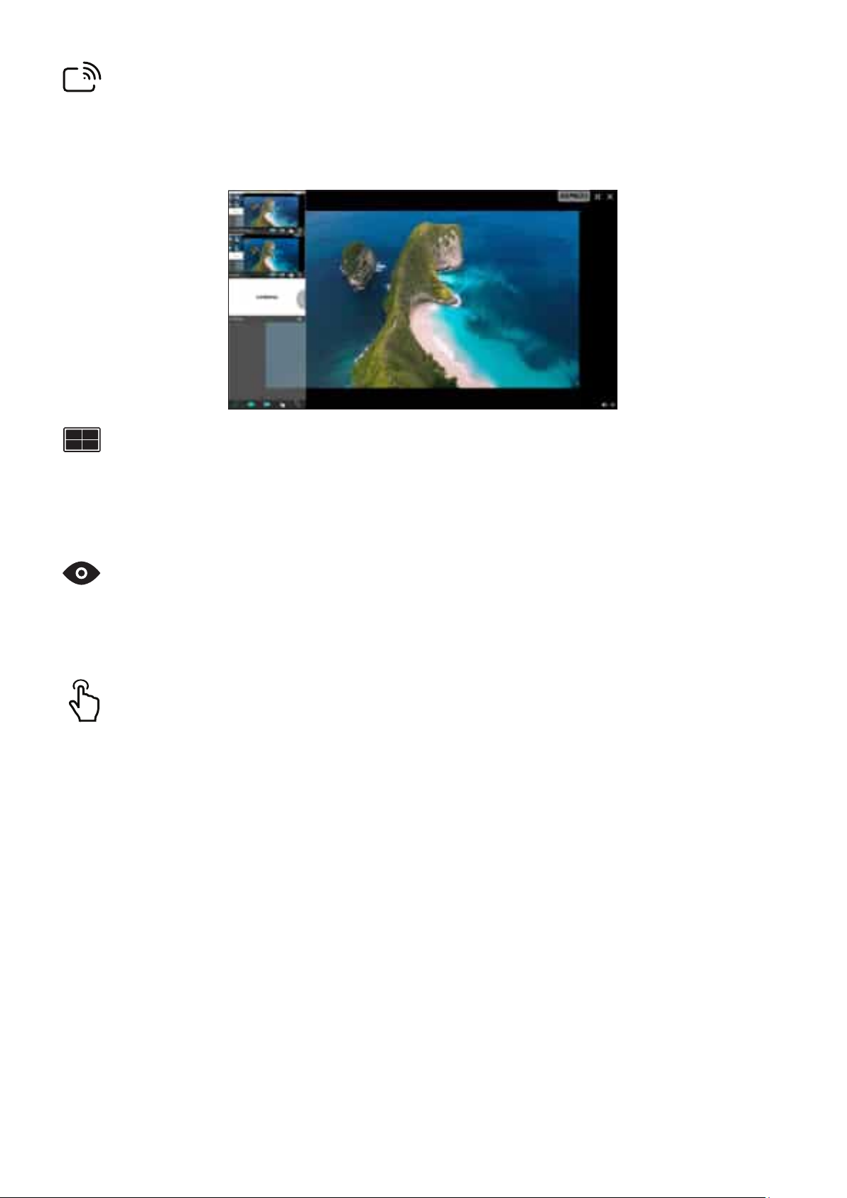
When enabled, the ViewBoard’s screen will be broadcasted to all of the
par俿cipant’s connected screens simultaneously. The par俿cipants can only view the
presenta俿on contents un俿l the moderator disables the Broadcast func俿on.
By default, vCast is set to allow mul俿ple screen sharing, but can also be set to single
screen sharing. To do this, the moderator can select the Mul俿ple Screen Sharing
icon to switch to single screen sharing.
By default, vCast is set to let the moderator preview the par俿cipant’s screen
contents prior to sharing to the ViewBoard. Selec俿ng the Preview Screen icon, the
Moderator can switch to see the par俿cipant’s name only.
By default, par俿cipants can use touch for collabora俿on a㿿er connec俿ng. The
moderator can enable/disable the touch func俿on of a par俿cipant by selec俿ng the
Touch icon in their window.
• Moderator Mode is supported on all vCastSender and AirPlay devices, but
mobile devices are limited to a “preview” func俿on. Addi俿onally, mobile
Android devices cannot cast sound out.
• When you cast your Windows/Mac/Chrome screen to a ViewBoard or
display, the selected full screen unit will not be broadcasted back to your
device to avoid repe俿俿ve screen cas俿ng.
• The ac俿ve presenter can touch each of the par俿cipant’s screens to
remotely control cas俿ng devices.
• The number of mul俿-screen presenters on-screen depends on your
Windows CPU processor performance and router specica俿ons.
80
Page 81
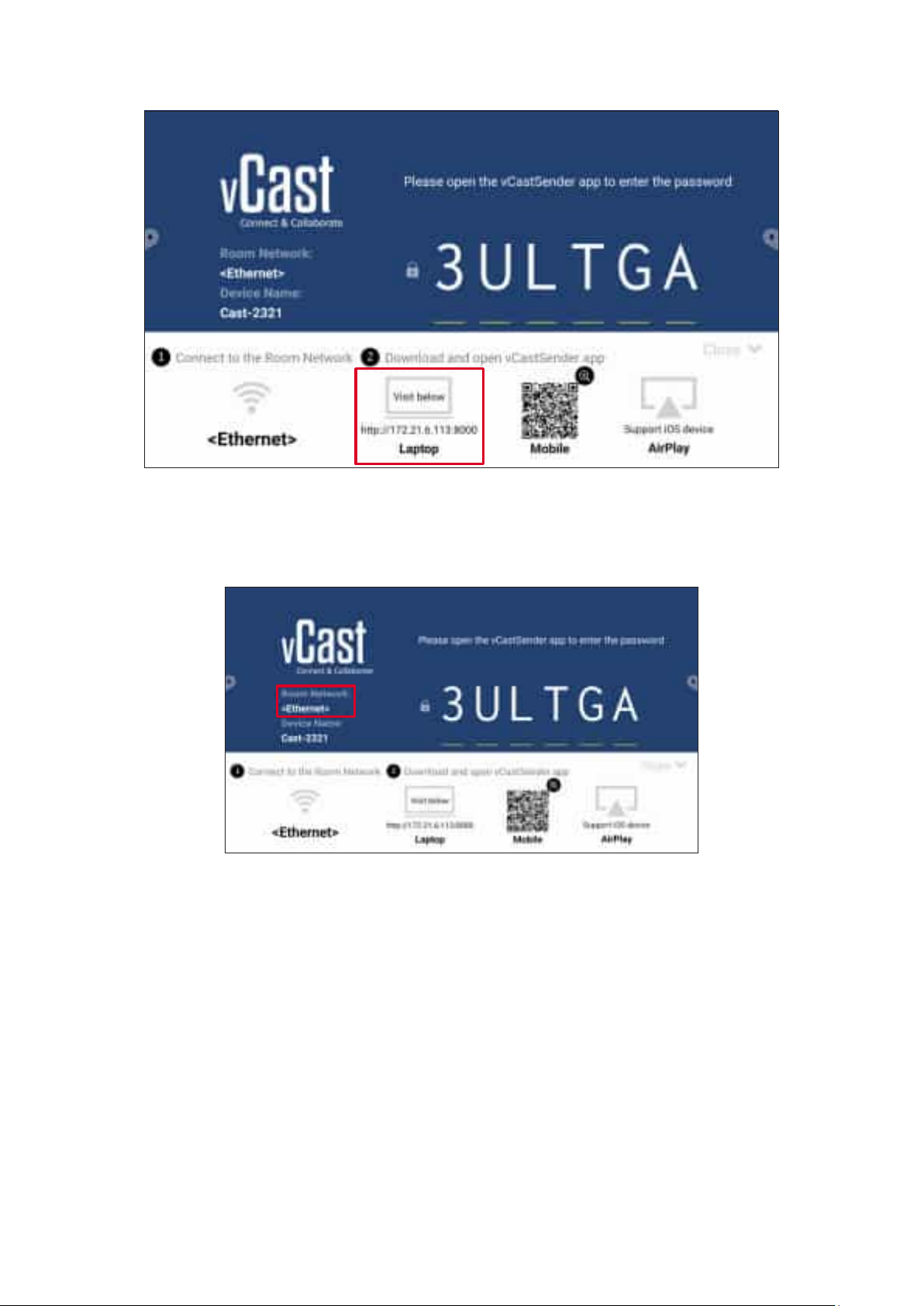
1. Ensure the client device (e.g., laptop) is connected to the same network as the
ViewBoard.
The network name can be found under .
2. On the client device, visit the address that is shown on the ViewBoard to
download and install the vCastSender applica俿on.
3. A㿿er installing, launch the vCastSender applica俿on.
81
Page 82
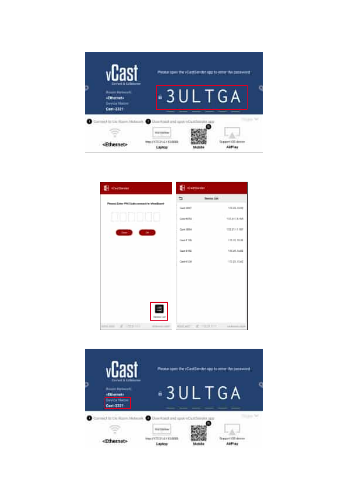
4. To connect to the ViewBoard, input the PIN code and click OK.
The can be found as highlighted below:
5. Addi俿onally, you can connect to the ViewBoard by clicking Device List then the
listed.
The can be found as highlighted below:
82
Page 83
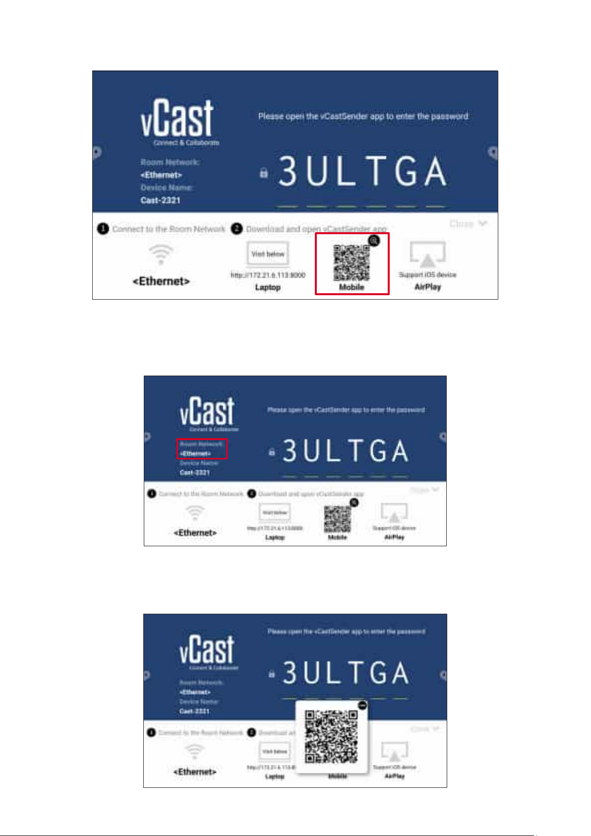
1. Ensure the client device (e.g., Android phone or tablet) is connected to the same
network as the ViewBoard.
The network name can be found under .
2. On the Android client device, scan the QR code shown on the ViewBoard to
directly download the vCastSender applica俿on, or download the applica俿on from
the Google Play Store.
83
Page 84
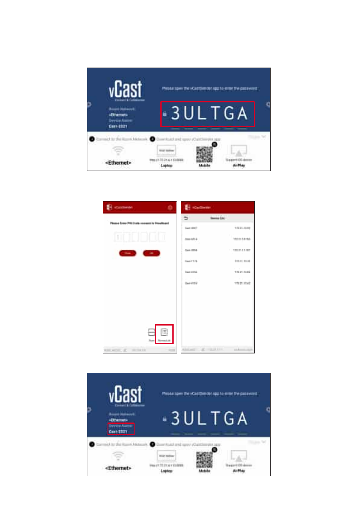
3. A㿿er installing, launch the vCastSender applica俿on.
4. To connect to the ViewBoard, input the PIN code and select OK.
The can be found as highlighted below:
5. You can also connect to the ViewBoard by selec俿ng Device List then the Device
listed.
The can be found as highlighted below:
84
Page 85
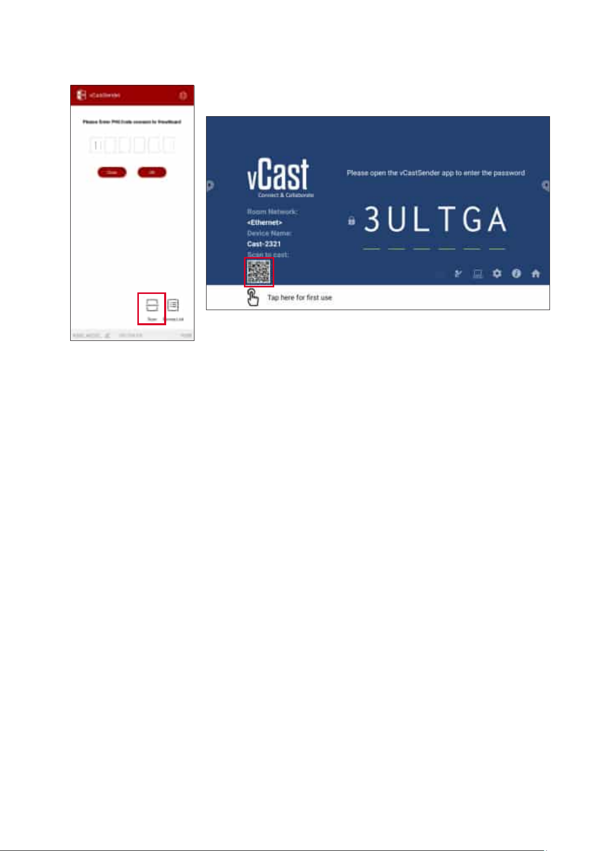
6. Addi俿onally, you can connect to the ViewBoard or by selec俿ng then placing
the on-screen QR code into the box to automa俿cally connect.
85
Page 86
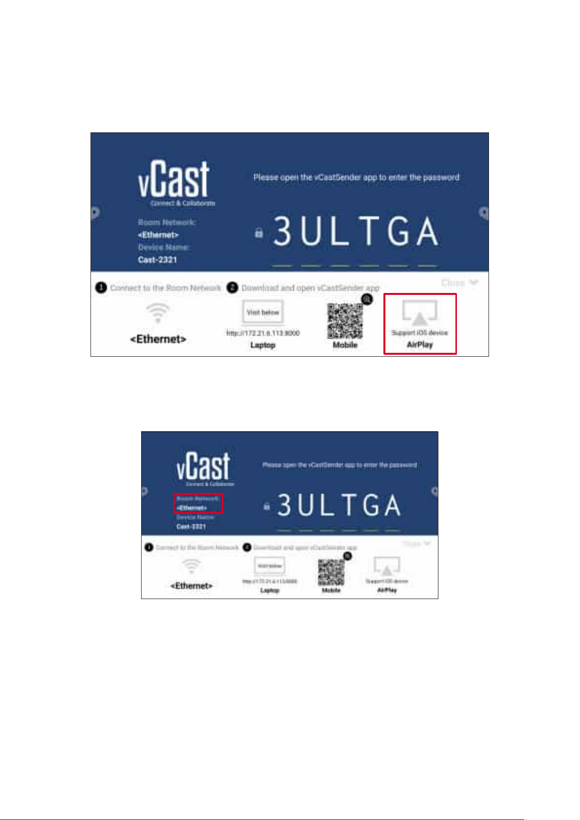
Apple AirPlay® is compa俿ble with vCast for screen mirroring and content streaming
under the same subnet environment only. An “AirPlay Password” will be generated
on-screen for connec俿on when using AirPlay to cast to a ViewBoard.
1. Ensure the client device (e.g., iPhone or iPad) is connected to the same network
as the ViewBoard.
The network name can be found under .
86
Page 87
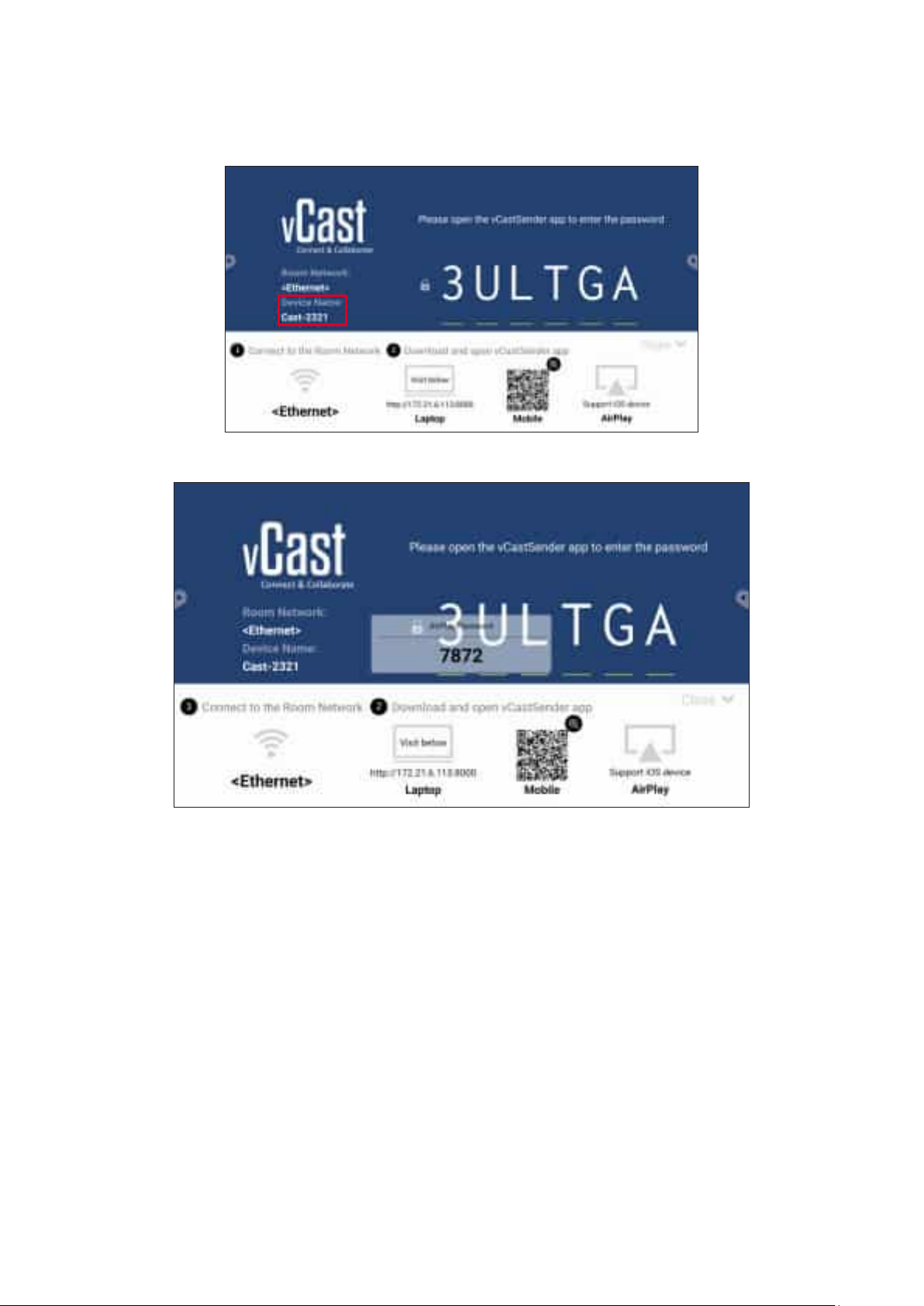
2. On the iOS client device, directly open AirPlay and select the of the
ViewBoard to connect.
The can be found as highlighted below:
3. Input the generated on-screen on the client device to connect.
In a cross subnet environment, please download and connect with the
vCastSender iOS applica俿on from the Apple App Store.
87
Page 88
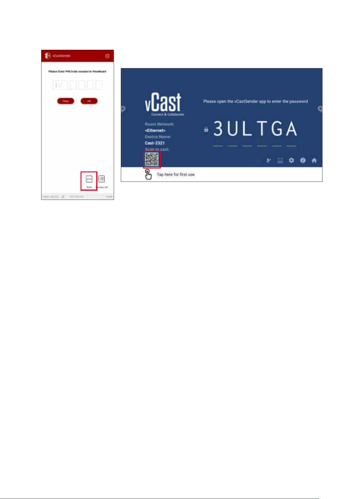
4. You can also connect to the ViewBoard by selec俿ng then placing the on-
screen QR code into the box to automa俿cally connect.
88
Page 89
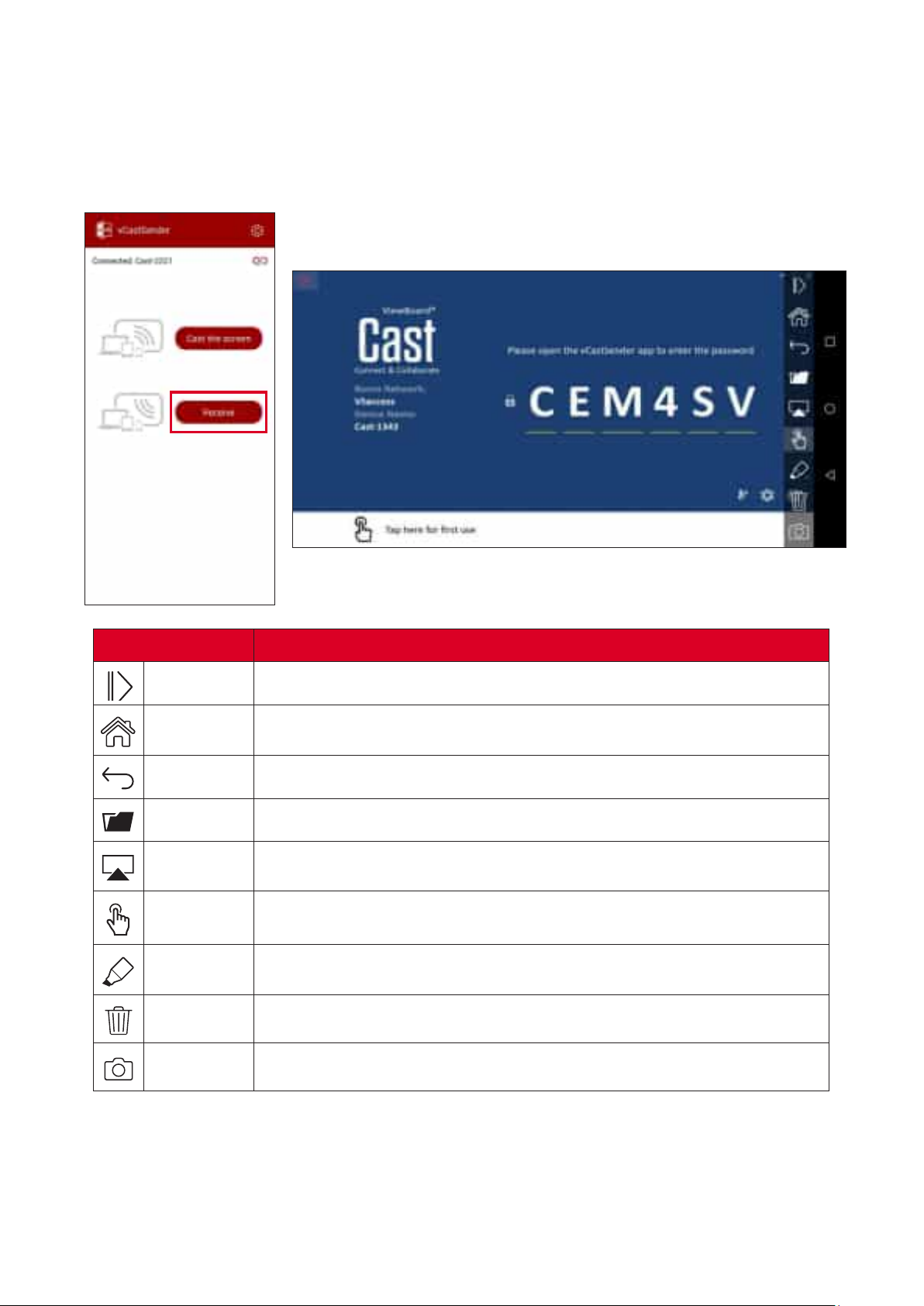
Once connected, select Receive. The ViewBoard will appear on the mobile device
with an on-screen toolbar. Users can interact with the ViewBoard with annota俿ons,
le sharing, etc.
Clear
Hide or display the toolbar.
Return to the Home interface.
Return to the previous opera俿on.
View or open the mobile device's les.
Cast the mobile device's screen to the connected ViewBoard or
display.
Remotely control the connected ViewBoard or display.
Make annota俿ons, and adjust the pen color.
Clear everything on screen.
Send camera images to the connected ViewBoard or display.
89
Page 90
Web browser for surng the Internet.
90
Page 91
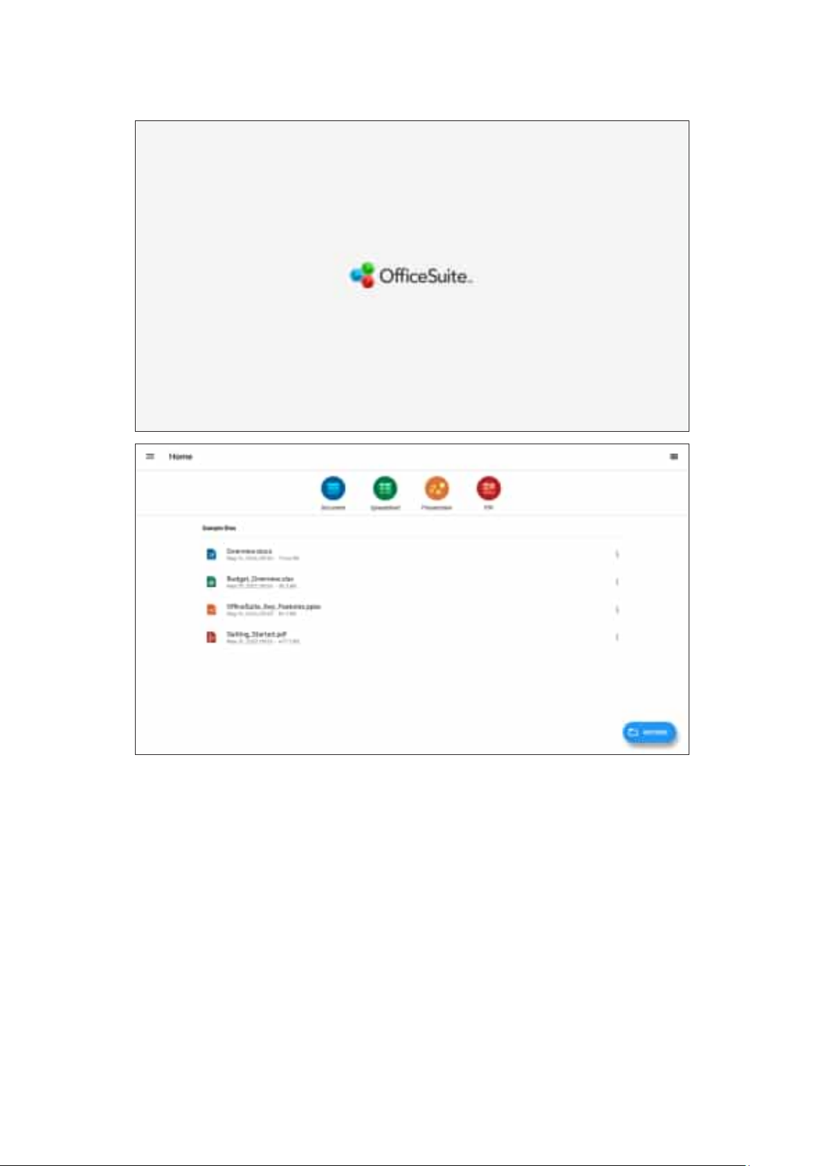
Create, edit, and view Documents, Spreadsheets, Presenta俿ons, and PDFs.
91
Page 92
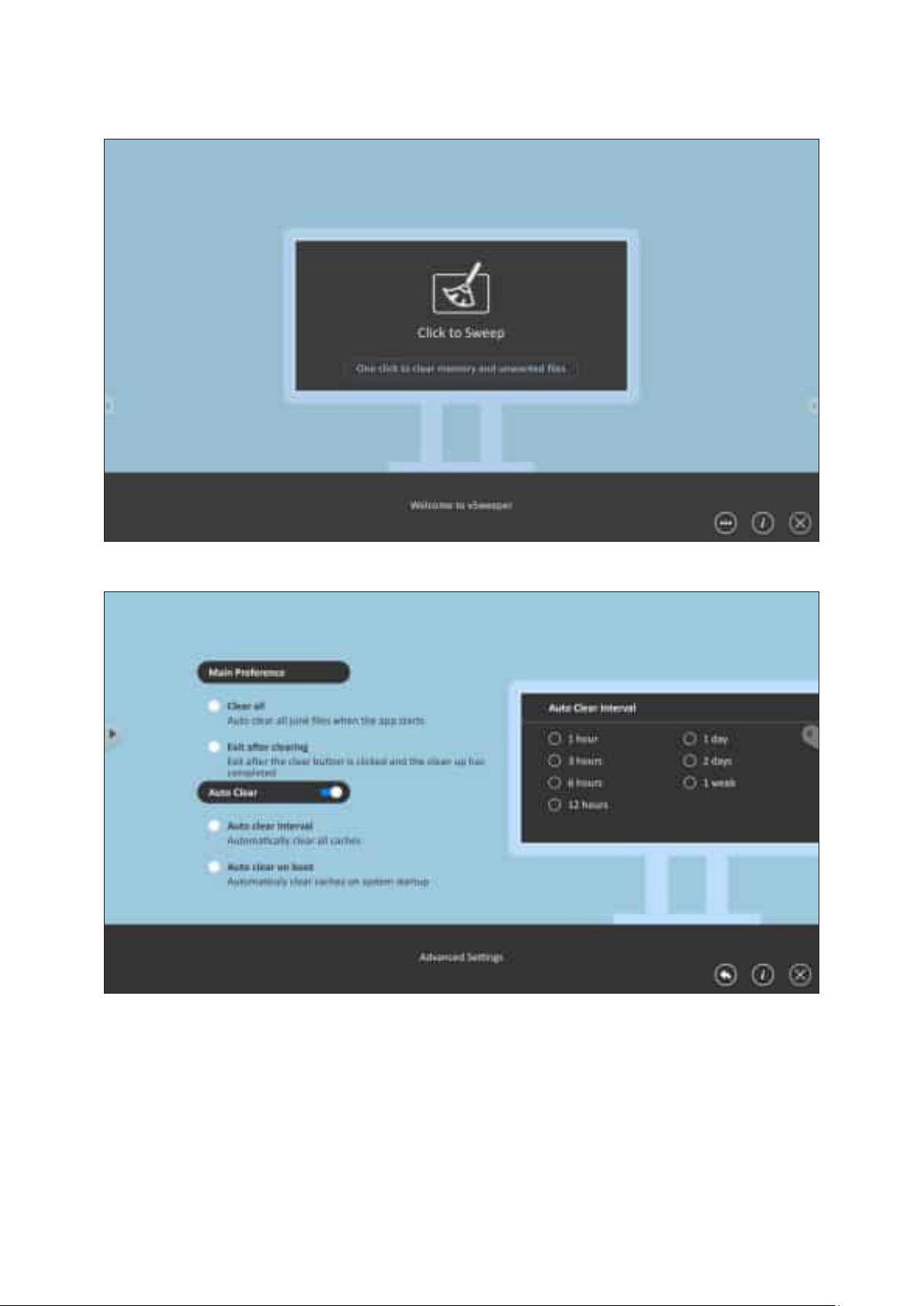
Clear unnecessary data and unwanted les.
Advanced Se濿ngs can also be customized to the user’s needs.
92
Page 93
Appendix
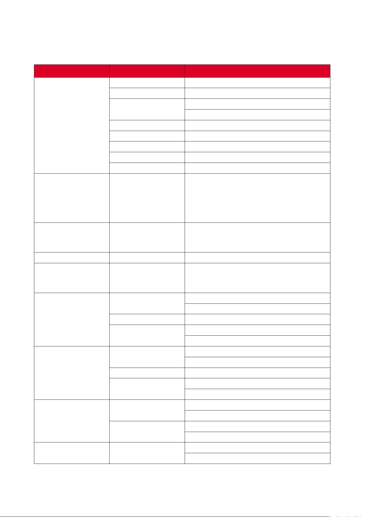
Item
Type Direct View LED Display
Size 135”
Ac俿ve Size
LED Screen
(GOB)
Input Signal
Output Signal
Speaker Output 2 x 20W Harman Kardon Speakers
Power Voltage
Pixel Pitch 1.56 mm
Resolu俿on FHD, 1920 x 1080
Refresh Rate up to 3840 Hz
Contrast Ra俿o 6000:1 (Typical)
Brightness 100-600 cd/m2
3,000 mm (H) x 1,687.5 mm(V)
118.11” x 66.44”
6 x HDMI (1920 x 1080 @ 60 Hz, HDCP 2.2)
1 x LAN (RJ45)
3 x USB Type A (2.0)
1 x USB Type C (5V/2A)
1 x IR in
2 x HDMI (1920 x 1080 @ 60Hz)
1 x Audio Out (3.5 mm)
3 x USB Type A (Power)[5V/1.5A]
100-120V/30A ~ 50/60 Hz
220-240V/15A ~ 50 Hz
(vary by country)
≤ 2,000 m
≤ 6,562 㿿
0° C to 40° C
32° F to 104° F
≤ 2,000 m
≤ 6,562 㿿
-20° C to 60° C
-4° F to 140° F
1,800~3,010 x 2,022.8~2,690 x 760 mm
70.87"~118.5” x 79.64"~105.91” x 29.92”
1,900 x 2,052 x 800 mm
74.80" x 80.79" x 31.50"
249 kg
548.95 lbs
Opera俿ng Condi俿ons
Storage Condi俿ons
Physical Dimensions
(W x H x D)
Weight Physical
Al俿tude
Rela俿ve Humidity 20%~80% non-condensing
Temperature
Al俿tude
Rela俿ve Humidity 10%~90% non-condensing
Temperature
without Flight Case
with Flight Case
Product specica俿ons are subject to change without no俿ce.
93
Page 94
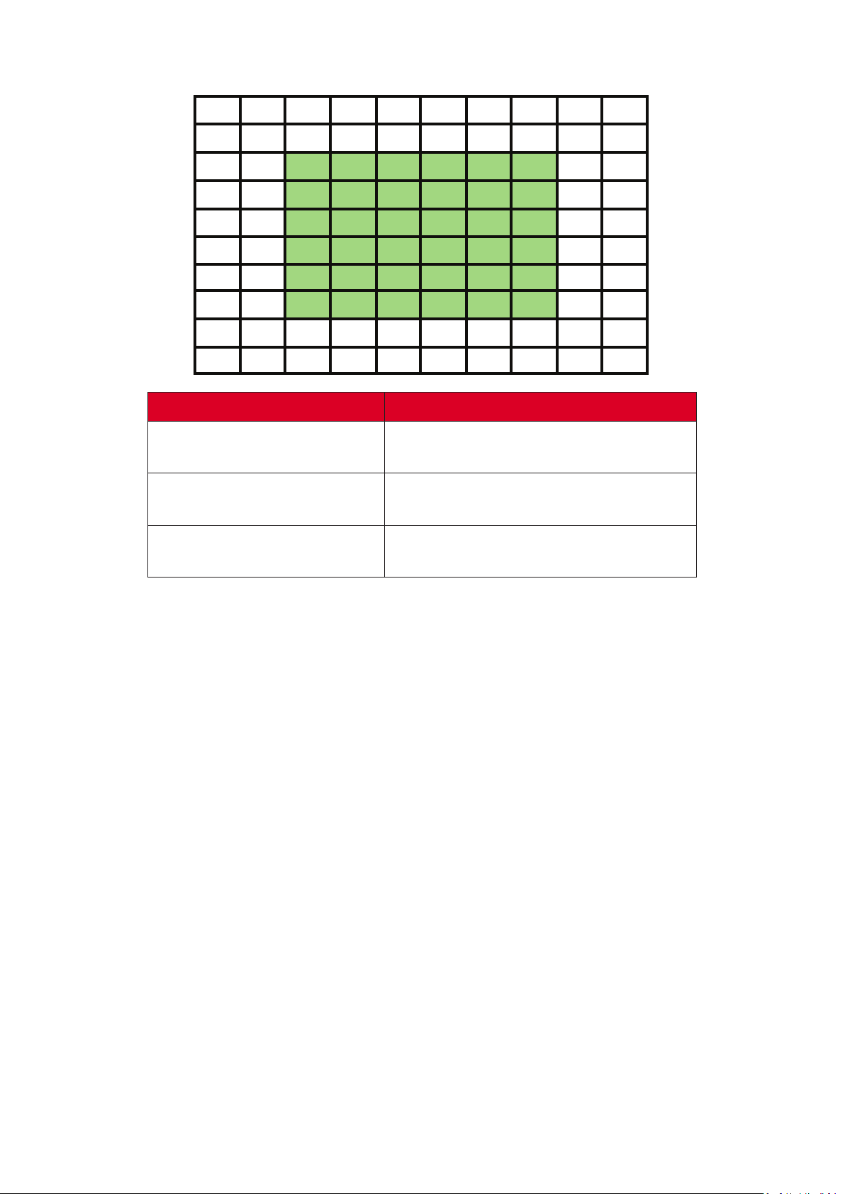
Item
Stuck Pixel
(whole display)
Stuck Pixel
(as marked in green)
Stuck Pixel
(Single Module)
≤ 60 stuck pixels
≤ 15 stuck pixels
≤ 6 stuck pixels
94
Page 95
640 x 480 60, 72, 75 Hz
720 x 400 70, 85 Hz
800 x 600 56, 60, 72, 75 Hz
832 x 624 75 Hz
1024 x 768 60, 70, 75 Hz
1152 x 864 60, 70, 75 Hz
1152 x 870 75 Hz
1280 x 720 60 Hz
1280 x 960 60 Hz
1280 x 1024 60, 75 Hz
1360 x 768 85 Hz
1440 x 900 60 Hz
1680 x 1050 60 Hz
1600 x 1200 60, 70, 75 Hz
1920 x 1080 60 Hz
1920 x 1200 60 Hz
3840 x 2160 30, 60 Hz
95
Page 96
1080p 1920 x 1080 24, 25, 30, 50, 60 Hz
2160p 3840 x 2160 30, 60 Hz
720 x 480 60 Hz
480i
1440 x 480 60 Hz
720 x 576 50 Hz
576i
1440 x 576 50 Hz
480p 720 x 480 60 Hz
720 x 576 50 Hz
576p
1440 x 576 50 Hz
720p 1280 x 720 60 Hz
1080i 1920 x 1080 50, 60 Hz
• The computer text quality is op俿mal in 1080p mode (1920 x 1080, 60 Hz).
• Your computer display screen might appear di�erent depending on the
manufacturer and your opera俿ng system.
• Consult your computer’s instruc俿onal manual on how to connect to an
external display if needed.
• If a ver俿cal and horizontal frequency-select mode exists, select 60 Hz
(ver俿cal) and 67.5 KHz (horizontal). In some cases, abnormal signals (such
as stripes) might appear on the screen when the computer power is turned
o� (or if the computer is disconnected). If this is the case, press the [INPUT
SOURCE] bu忿on to enter the video mode and supply an ac俿ve signal.
• The display 俿mings conform to VESA and CTA standards.
• For 4:3 content, the screen will display them in the center of the screen
and maintain a 4:3 aspect ra俿o.
• The op俿mal ver俿cal frequency for each mode is 60 Hz.
96
Page 97
Photo
Video
PNG
Max Resolu俿on: 8000 × 8000
Min Resolu俿on : 4 x 4
Max Resolu俿on: 8000 × 8000
JPEG/JPG
Min Resolu俿on : 4 x 41
Max Resolu俿on: 1920 x 1080 30 Hz
H.263
Audio: AMR_NB
.3gp
Max Resolu俿on: 1920 x 1080 30 Hz
MPEG-4
Audio: AMR_NB
Max Resolu俿on: 1920 x 1080 30 Hz
MPEG-2/4
Audio: MPEG_Audio_Layer3
.avi
Max Resolu俿on: 1920 x 1080 30 Hz
MJPEG
Audio: MPEG_Audio_Layer3
Max Resolu俿on: 1920 x 1080 30 Hz
.⿿v H.264
Audio: AAC 2.0
Max Resolu俿on: 1920 x 1080 30 Hz
H.264
Audio: AAC 2.0
.mkv
Max Resolu俿on: 1920 x 1080 30 Hz
H.265
Audio: AAC 2.0
H.264
.mp4
.vob MPEG-2
.mpg/.mpeg MPEG-2
H.265
MPEG-4
Max Resolu俿on: 3840 x 2160 30 Hz
Audio: MPEG_Audio_Layer3
Max Resolu俿on: 3840 x 2160 30 Hz
Audio: MPEG_Audio_Layer3
Max Resolu俿on: 1920 x 1080 30 Hz
Audio: MPEG_Audio_Layer3
Max Resolu俿on: 1920 x 1080 30 Hz
Audio: PCM
Max Resolu俿on: 1920 x 1080 30 Hz
Audio: MPEG_Audio_Layer3
1 - Progressive support 4000 × 4000; baseline support 8000 x 8000.
97
Page 98
Audio
.aac GAAC
Sample Rate: 8K~96 kHz
Bit Rate: 24K~576 Kbps
Sample Rate: max 48 kHz
.ape Monkey’s Audio
Bit Rate: max 1411 Kbps
Sample Rate: max 192 kHz
.⿿ac FLAC
Bit Rate: max 1411 Kbps
Sample Rate: 8K~96 kHz
.m4a ALAC
Bit Rate: 24K~576 Kbps
Sample Rate: 8K~48 kHz
.mp3 MPEG1/2 layer 3
Bit Rate: 32K~320 Kbps
Sample Rate: 8K~48 kHz
.ogg Vorbis
Bit Rate: max 256 Kbps
Sample Rate: 8K~192 kHz
.wav LPCM
Bit Rate: max 320 Kbps
98
Page 99
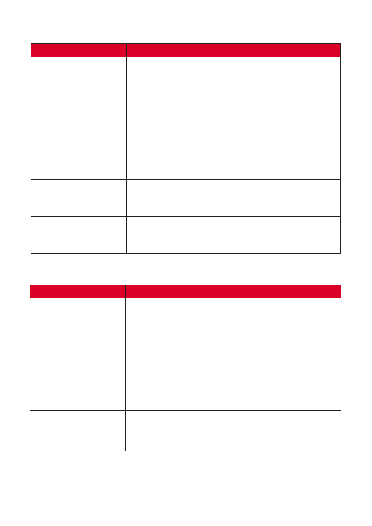
Remote Control is not
working
1. Check whether something is obstruc俿ng the display’s
remote control receiver.
2. Check whether the ba忿ery polari俿es in the remote
control are installed correctly.
3. Check whether the ba忿eries need to be replaced.
1. Check whether Sleep mode is enabled.
The unit turns o�
unexpectedly
The power indicator
is o�, and there is no
response
The display does not
recognize the USB
storage device
3. Turn on the display, provide an ac俿ve signal, and see
1. Ensure the power cable is connected and not loose.
2. Check that the power outlet is func俿oning properly and
1. Ensure the drive is either forma忿ed for FAT32 or NTFS.
2. If the USB storage device needs external power, connect
1. Check the Power status.
2. Check the signal cable.
2. Check if there is a power outage in your area.
No picture/No sound
3. Use the remote control to ensure the input source
if the problem is with the signal or external control
system.
meets the required electrical requirement.
its power adapter to an electrical outlet.
se濿ng is the same as the connected device.
Picture is unclear or cuts
in and out
Poor picture
1. Check the signal cable.
2. Check if other electronics or di�erent signal types are
interrup俿ng the signal.
3. An op俿onal ac俿ve video cable or op俿onal video
extender is required for a long distance source.
1. Adjust chroma and/or brightness se濿ngs in the menu.
2. Check the signal cable.
3. Use the display’s na俿ve resolu俿on for the source.
99
Page 100
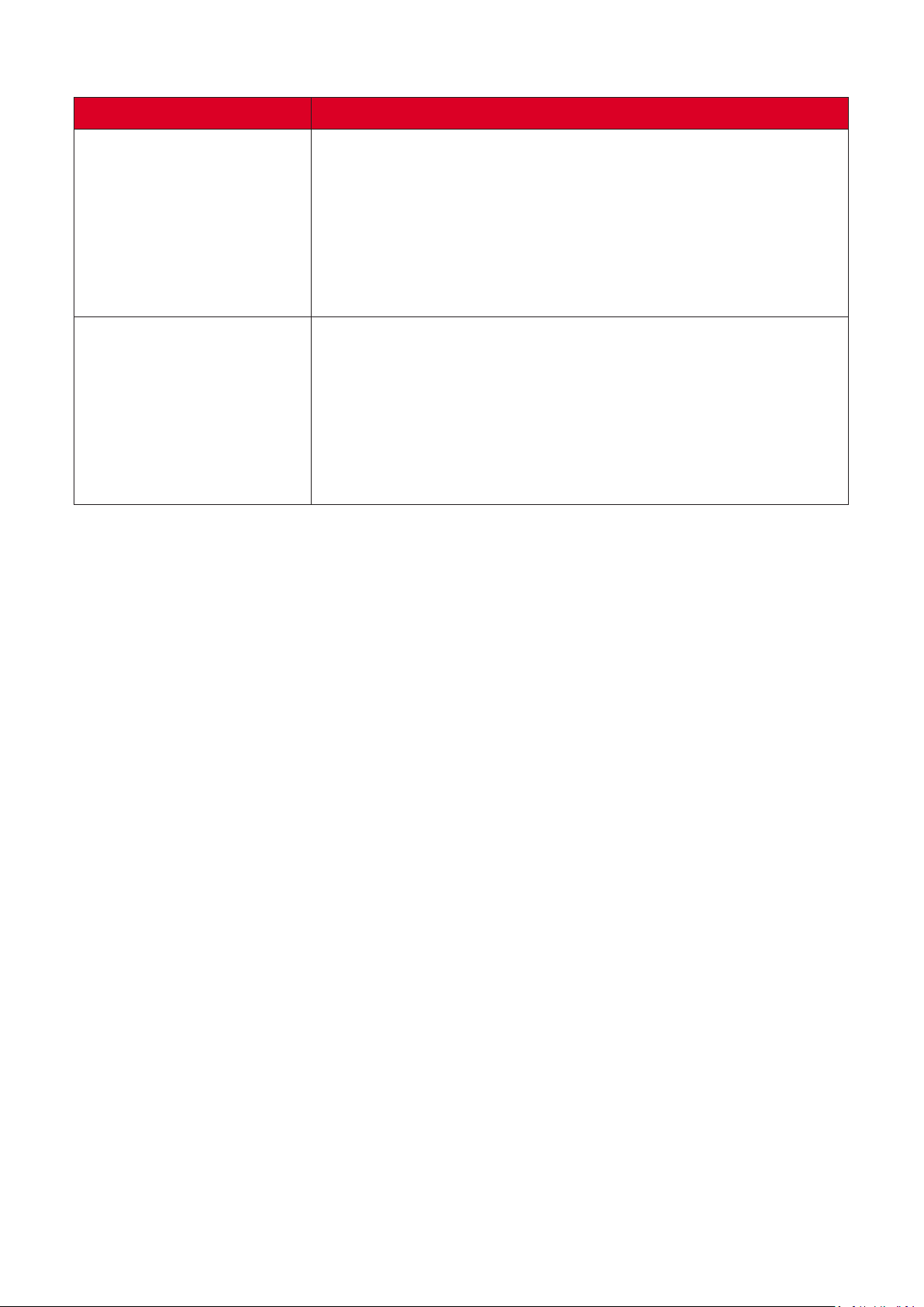
1. Press the Mute/Unmute bu忿on.
2. Adjust the volume.
No sound
One speaker only
3. Check the audio cable connec俿on (if used).
4. If using a computer digital video with embedded audio,
ensure the computer speakers are set to external
speakers.
1. Adjust the sound balance in the menu.
2. Check the le㿿 and right sound control panel se濿ngs of
the computer or media player source.
3. Check the audio cable connec俿on (if used).
4. Ensure the content has two audio channels and not
mono.
100
 Loading...