

Page 1

IFP5550/IFP6550
IFP7550/IFP8650
Commercial Touch Display
User Guide
IMPORTANT: Please read this User Guide to obtain important information on installing
and using your product in a safe manner, as well as registering your product for future
service. Warranty information contained in this User Guide will describe your limited
coverage from ViewSonic Corporation, which is also found on our web site at http://
www.viewsonic.com in English, or in specic languages using the Regional selection
box in the upper right corner of our website. “Antes de operar su equipo lea cu
idadosamente las instrucciones en este manual”
Model No. VS17121/VS16954/VS16876/VS16874
Page 2

Thank you for choosing ViewSonic
As a world leading provider of visual solutions, ViewSonic is dedicated to
exceeding the world’s expectations for technological evolution, innovation,
and simplicity. At ViewSonic, we believe that our products have the
potential to make a positive impact in the world, and we are confident that
the ViewSonic product you have chosen will serve you well.
Once again, thank you for choosing ViewSonic !
Page 3

Compliance Information
NOTE: This section addresses all connected requirements and statements regarding
regulations. Confirmed corresponding applications shall refer to nameplate labels
and relevant markings on unit.
FCC Compliance Statement
This device complies with part 15 of FCC Rules. Operation is subject to the following
two conditions: (1) this device may not cause harmful interference, and (2) this
device must accept any interference received, including interference that may cause
undesired operation.
This equipment has been tested and found to comply with the limits for a Class
B digital device, pursuant to part 15 of the FCC Rules. These limits are designed
to provide reasonable protection against harmful interference in a residential
installation. This equipment generates, uses, and can radiate radio frequency
energy, and if not installed and used in accordance with the instructions, may cause
harmful interference to radio communications. However, there is no guarantee that
interference will not occur in a particular installation. If this equipment does cause
harmful interference to radio or television reception, which can be determined
by turning the equipment off and on, the user is encouraged to try to correct the
interference by one or more of the following measures:
• Reorient or relocate the receiving antenna.
• Increase the separation between the equipment and receiver.
• Connect the equipment into an outlet on a circuit different from that to which the
receiver is connected.
• Consult the dealer or an experienced radio/TV technician for help.
Warning: You are cautioned that changes or modifications not expressly approved
by the party responsible for compliance could void your authority to operate the
equipment.
Industry Canada Statement
CAN ICES-3 (B)/NMB-3(B)
Contains FCC ID: 2AFG6-RK3399
IC ID: 22166-RK3399
CE Conformity for European Countries
The device complies with the EMC Directive 2014/30/EU and Low Voltage
Directive 2014/35/EU.
Following information is only for EU-member states:
The mark shown to the right is in compliance with the Waste Electrical and
Electronic Equipment Directive 2012/19/EU (WEEE).The mark indicates
the requirement NOT to dispose the equipment as unsorted municipal
waste, but use the return and collection systems according to local law.
i
Page 4
Indian Restriction of Hazardous Substances
Restriction on Hazardous Substances statement (India) This product complies
with the “India E-waste Rule 2011” and prohibits use of lead, mercury, hexavalent
chromium, polybrominated biphenyls or polybrominated diphenyl ethers in
concentrations exceeding 0.1 weight % and 0.01 weight % for cadmium, except for
the exemptions set in Schedule 2 of the Rule.
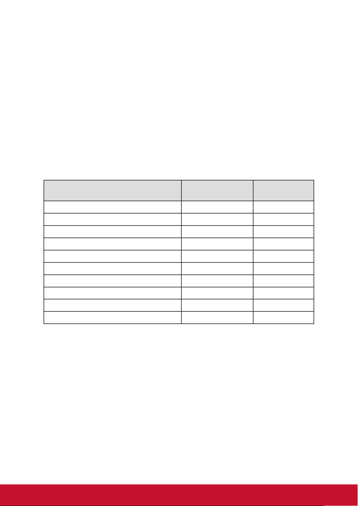
Declaration of RoHS2 Compliance
This product has been designed and manufactured in compliance with Directive
2011/65/EU of the European Parliament and the Council on restriction of the use
of certain hazardous substances in electrical and electronic equipment (RoHS2
Directive) and is deemed to comply with the maximum concentration values issued
by the European Technical Adaptation Committee (TAC) as shown below:
Substance
Lead (Pb) 0.1% < 0.1%
Mercury (Hg) 0.1% < 0.1%
Cadmium (Cd) 0.01% < 0.01%
Hexavalent Chromium (Cr
Polybrominated biphenyls (PBB) 0.1% < 0.1%
Polybrominated diphenyl ethers (PBDE) 0.1% < 0.1%
Bis (2-ethylhexyl) phthalate (DEHP) 0.1% < 0.1%
Butyl benzyl phthalate (BBP) 0.1% < 0.1%
Dibutyl phthalate (DBP) 0.1% < 0.1%
Diisobutyl phthalate (DIBP ) 0.1% < 0.1%
Certain components of products as stated above are exempted under the Annex III
of the RoHS2 Directives as noted below:
6+
) 0.1% < 0.1%
Proposed Maximum
Concentration
Actual
Concentration
Examples of exempted components are:
1. Mercury in cold cathode fluorescent lamps and external electrode fluorescent
lamps (CCFL and EEFL) for special purposes not exceeding (per lamp):
(1) Short length (≦500 mm): maximum 3.5 mg per lamp.
(2) Medium length (>500 mm and ≦1,500 mm): maximum 5 mg per lamp.
(3) Long length (>1,500 mm): maximum 13 mg per lamp.
2. Lead in glass of cathode ray tubes.
3. Lead in glass of fluorescent tubes not exceeding 0.2% by weight.
4. Lead as an alloying element in aluminium containing up to 0.4% lead by weight.
5. Copper alloy containing up to 4% lead by weight.
ii
Page 5

6. Lead in high melting temperature type solders (i.e. lead-based alloys containing
85% by weight or more lead).
7. Electrical and electronic components containing lead in a glass or ceramic other
than dielectric ceramic in capacitors, e.g. piezoelectronic devices, or in a glass or
ceramic matrix compound.
Cautions and Warnings
1. Read these instructions completely before using the equipment.
2. Keep these instructions in a safe place.
3. Heed all warnings and follow all instructions.
4. Always handle the LCD display with care when moving it.
5. Never remove the rear cover. This LCD display contains high-voltage parts.
You may be seriously injured if you touch them.
6. Do not use this equipment near water. Warning: To reduce the risk of fire or
electric shock, do not expose this apparatus to rain or moisture.
7. Avoid exposing the LCD display to direct sunlight or another heat source. Orient
the LCD display away from direct sunlight to reduce glare.
8. Clean with a soft, dry cloth. If further cleaning is required, see the “Care and
Maintenance” section in this guide for further instructions.
9. Do not block any ventilation openings. Install the equipment in accordance with
the manufacturer’s instructions.
10. Do not install near any heat sources such as radiators, heat registers, stoves, or
other devices (including amplifiers) that produce heat.
11. Place the LCD display in a well ventilated area. Do not place anything on the
LCD display that prevents heat dissipation.
12. Do not place heavy objects on the LCD display, video cable, or power cord.
13. If smoke, an abnormal noise, or a strange odor is present, immediately switch
the LCD display off and call your dealer or ViewSonic. It is dangerous to continue
using the LCD display.
14. Do not attempt to circumvent the safety provisions of the polarized or groundingtype plug. A polarized plug has two blades with one wider than the other. A
grounding type plug has two blades and a third grounding prong. The wide blade
and the third prong are provided for your safety. If the plug does not fit into your
outlet, consult an electrician for replacement of the outlet.
15. Protect the power cord from being tread upon or pinched, particularly at the plug,
and the point where if emerges from the equipment. Be sure that the power outlet
is located near the equipment so that it is easily accessible.
(Continued on next page)
iii
Page 6

16. Only use attachments/accessories specified by the manufacturer.
17. Use only with the cart, stand, tripod, bracket, or table specified by
the manufacturer, or sold with the equipment. When a cart is used,
use caution when moving the cart/equipment combination to avoid
injury from tipping over.
18. Unplug this equipment when it will be unused for long periods of time.
19. Refer all servicing to qualified service personnel. Service is required when the
unit has been damaged in any way, such as: if the power-supply cord or plug is
damaged, if liquid is spilled onto or objects fall into the unit, if the unit is exposed
to rain or moisture, or if the unit does not operate normally or has been dropped.
20. The Unit is a Monitor with LED backlight intended for general office used.
iv
Page 7

Contents
Compliance Information
FCC Compliance Statement ................................................................ i
Industry Canada Statement ................................................................. i
CE Conformity for European Countries ............................................... i
Indian Restriction of Hazardous Substances ......................................ii
Declaration of RoHS2 Compliance ......................................................ii
Cautions and Warnings ......................................................................iii
Copyright Information
For Your Records ............................................................................... 1
1. Getting Started
1.1 Package Contents ........................................................................ 2
1.2 Wall Mount Kit Specifications (VESA) .......................................... 3
2. Smart Whiteboard/LCD Display
Features
2.1 Control Panel Overview ................................................................ 4
2.2 Terminal Interface Overview ........................................................ 5
2.3 Remote Control Overview ............................................................ 6
2.4 Inserting Remote Control Batteries .............................................. 7
2.5 Remote Control Receiver Range ................................................. 8
3. Setting Up Your Display
3.1 Connecting an External Device .................................................... 9
3.2 RS232 Connections ................................................................... 10
3.3 Connecting USB Peripherals ...................................................... 11
3.4 AV IN Connections ..................................................................... 12
3.5 Connecting to a media player ..................................................... 13
3.6 Coaxial Connections .................................................................. 13
3.7 Video Output Connection ........................................................... 14
v
Page 8

4. ViewBoard Basic Operation
4.1 vLauncher for customized welcome screen .............................. 16
4.2 Tool Bar
4.3 ViewBoard OSD (on screen display) Menu ................................ 24
5. ViewBoard Embedded Application and Setting
5.1 Embedded Digital Whiteboard App ............................................ 49
5.2 ViewBoard Cast .......................................................................... 55
5.3 Air Class ..................................................................................... 59
5.4 Other default apps ...................................................................... 63
6. Trouble Shooting
7. Care and Maintenance
8. Display Modes
8.1 VGA Mode .................................................................................. 75
8.2 HDMI Mode ................................................................................ 76
8.3 DP Mode .................................................................................... 77
9. Specifications
10. RS-232 Protocol
10.1 Introduction ............................................................................... 79
10.2 Description ............................................................................... 79
10.3 Protocol .................................................................................... 81
Warranty Statement
Limited Warranty .............................................................................. 97
Mexico Limited Warranty .................................................................. 99
vi
Page 9

Copyright Information
Copyright © ViewSonic Corporation, 2018. All rights reserved.
Macbook, Macbook Pro, Mac OS, iOS are registered trademarks of Apple Inc.
Microsoft, Windows, and the Windows logo are registered trademarks of Microsoft
Corporation in the United States and other countries.
ViewSonic, the three birds logo, OnView, ViewMatch, and ViewMeter are registered
trademarks of ViewSonic Corporation.
VESA is a registered trademark of the Video Electronics Standards Association.
DPMS, DisplayPort, and DDC are trademarks of VESA.
Disclaimer: ViewSonic Corporation shall not be liable for technical or editorial errors
or omissions contained herein; nor for incidental or consequential damages resulting
from furnishing this material, or the performance or use of this product.
In the interest of continuing product improvement, ViewSonic Corporation reserves
the right to change product specifications without notice. Information in this
document may change without notice.
No part of this document may be copied, reproduced, or transmitted by any means,
for any purpose without prior written permission from ViewSonic Corporation.
For Your Records
Product Name:
Model Number:
Document Number:
Serial Number:
Purchase Date:
Product disposal at end of product life
ViewSonic respects the environment and is committed to working and living green.
Thank you for being part of Smarter, Greener Computing.
Please visit ViewSonic website to learn more.
USA & Canada: http://www.viewsonic.com/company/green/recycle-program/
Europe: http://www.viewsoniceurope.com/eu/support/call-desk/
Taiwan: http://recycle.epa.gov.tw/
IFP5550/IFP6550/IFP7550/IFP8650
ViewSonic Commercial Touch Display
VS17121/VS16954/VS16876/VS16874
IFP5550/IFP6550/IFP7550/IFP8650_UG_ENG
Rev. 1E 11-05-18
_______________________________________
_______________________________________
1
Page 10
1. Getting Started
IFP50 series
Commercial Touch Display
Quick Start Guide
Package Contents
2
inch VESA Spec. (A x B) Standard Screw (C x D) Quantity
IFP6550 - 65” 600 x 400 mm M8 x 25 mm 4
IFP7550 - 75” 800 x 400 mm M8 x 25 mm 4
IFP8650 - 86" 800 x 600 mm M8 x 25 mm 4
● VGA cable
● Power cable x 4
● Remote control
● AAA battery x 2
● USB cable
● Audio cable
● AV cable
● Stylus pen x 3
● User manual CD wizard
● Quick start guide
● RS232 adapter
● Clamp x 5
● Plate
● Screw x 3
PN-WMK-047
3
Control Panel Overview
Wall Mount Kit Specifications (VESA)
Congratulations on your purchase of a ViewBoard
Important! Save the original box and all packing material for future shipping needs.
Note: The word “Windows” in this user guide refers to Microsoft Windows operating
system.
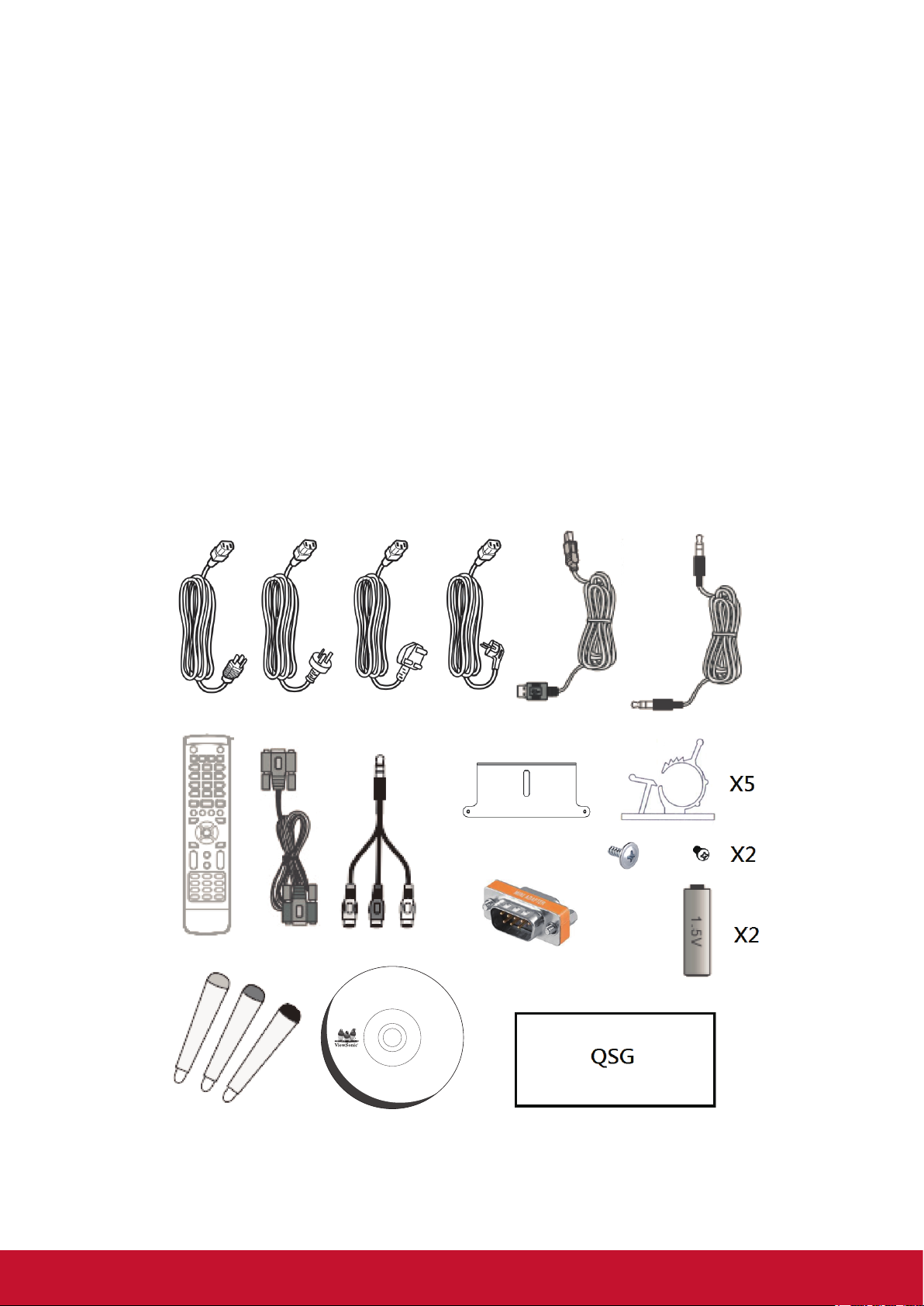
1.1 Package Contents
• VGA cable
• Power cable x 4
• Remote control
• AAA battery x 2
• USB cable
• Audio cable
• AV cable
• Stylus pen x 3
• User manual CD wizard
• Quick start guide
• RS232 adapter
• Clamp x 5
• Plate
• Screw x 3
User Guide and
Installation Software
CDE5561T/CDE6561T/CDE7061T/IFP7561T/
CDE8452T/SWB5561B/SWB6561B/
SWB7061B/SWB8452B
Copyright © 2016, ViewSonic Corporation. All rights reserved. All trademarks,
registered or otherwise, are the property of their respective companies. Disclaimer:
ViewSonic Corporation shall not be liable for technical or editorial reeors or omissions
contained herein; nor for incidental or consequential damages resulting from
furnishing this meterial, or the performance or use of this product. In the interest of
continuing product improvement, ViewSonic Corporation reserves the right to
change product specifications without notice. Information in this CD-ROM may
change without notice, No part of this CD-ROM may be copied, reproduced, or
transmitted by any means, for any purpose without prior written permission of
ViewSonic Corporation.
07/13/16 • CDE61T_UG • Made in China
PC System Requirements
Intel® Pentium® processor or
greater running on
Windows® Platform,
4x CD-ROM drive; 64MB or
more of available RAM;
800x600 color display.
Mac® System Requirements
Mac OS version 10.x;
4x CD-ROM drive; 64MB or
more of available RAM;
800x600 color display.
2
Page 11
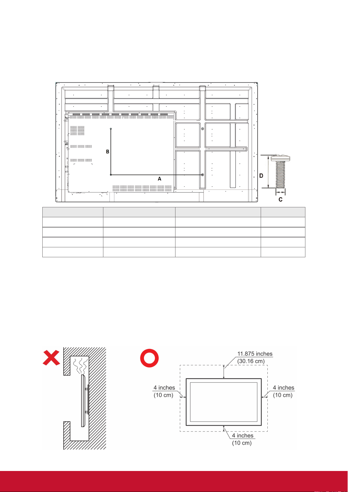
1.2 Wall Mount Kit Specications (VESA)
Please follow the instructions in the wall mount installation guide to install your
wall mount or mobile mount bracket. If attaching to other building materials, please
contact your nearest dealer.
A
B
inch VESA Spec. (A x B) Standard Screw (C x D) Quantity
IFP5550 - 55” 400 x 400mm M8 x 25 mm 4
IFP6550 - 65” 600 x 400 mm M8 x 25 mm 4
IFP7550 - 75” 800 x 400 mm M8 x 25 mm 4
IFP8650 - 86” 800 x 400 mm M8 x 25 mm 4
• ViewSonic provides the standard dimensions for wall mount kits as shown in the
table above.
• To find the perfect mount, please browse www.viewsonic.com or call our service
team.
• When purchasing our wall mount kit, a detailed install manual and all parts
necessary for assembly are provided.
• Do not use the screws that longer than the standard dimension, as they may
cause damage to the inside of the LCD display set.
3
Page 12
2. Smart Whiteboard/LCD Display
Features
This section introduces you to the features of ViewBoard hardware platform.
Note: The features or applications described in this User’s manual may vary
depending on the device model purchased.
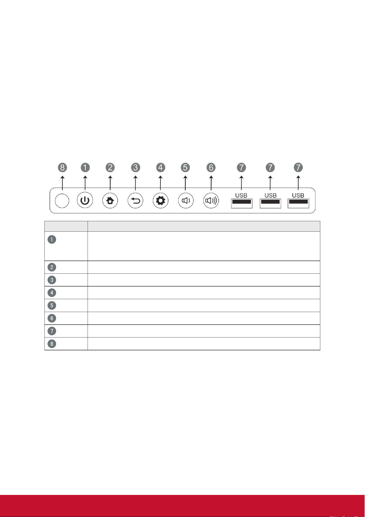
2.1 Control Panel Overview
Item Description
Press the key to turn on the device
Press the key to turn on/off the screen
Press and hold the key to turn off the device
Back to Embedded Player main interface
Return to Embedded Player previous level
Call up function menu
Decrease volume
Increase volume
USB port for Embedded Player and internal PC
Receives signals from the remote control
4
Page 13
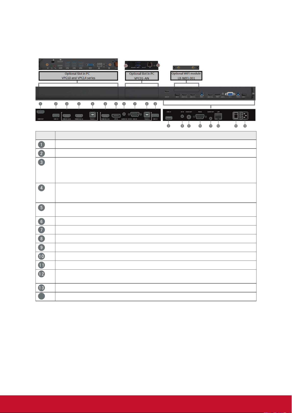
2.2 Terminal Interface Overview
Item Description
Extend content out to another display devices
USB port for Embedded Player
High-definition multimedia interface signal input, connect to PC with HDMI
output, set-top box, or other video device
HDMI 1 supports up to 3840x2160@60Hz
HDMI 2 and 3 support up to 3840x2160@30Hz
Touch signal output to the external PC
Touch 1 for HDMI IN 1 and 2
Touch 2 for HDMI IN 3, DP IN and VGA IN
Connected to devices with DisplayPort output function
DP supports up to 3840x2160@30Hz
14
External computer audio input
External computer image input
Composite video and audio input
Coaxial output
Serial interface, used for mutual transfer of data between devices
Audio output to the external speaker
Standard RJ45 (10/100MHz) Internet connection interface(This network
port is used for Embedded Player and Slot in PC)
Power On / Off switch
AC power input
5
Page 14
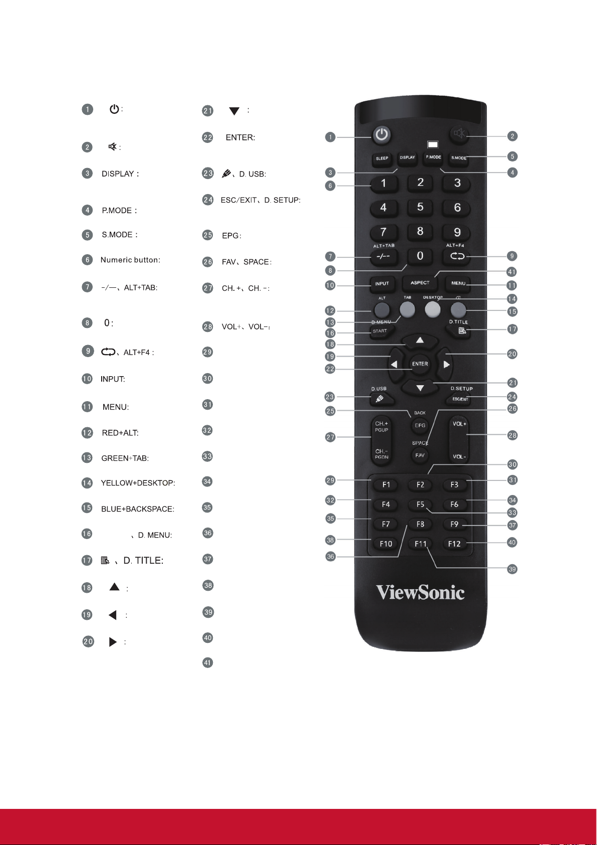
2.3 Remote Control Overview
Press to turn the display
ON/OFF
Mute / Unmute
Display information of the
current input source
Blank screen
Freeze screen
Numeric input button
Press to switch between
PC applications
Numeric input button
Close current PC window
Source selection button
Press to display Menu
Screen capture
PC ‘Tab’ button
Switch to slot in PC desktop
PC ‘Backspace’ button
START
PC ‘Windows’ button
PC ‘Menu’ button
Press to scroll up
Press to scroll left
Press to scroll right
Press to scroll down
Enter button. Press it to
select options.
Writing software startup
Shortcut button to exit
dialog boxes
Back
PC ‘Space’ button
CH+ : PC previous page
CH- : PC next page
Increase / Decrease volume
F1:
Windows F1 Function
F2:
Windows F2 Function
F3:
Windows F3 Function
F4:
Windows F4 Function
F5:
Windows F5 Function
F6:
Windows F6 Function
F7:
Windows F7 Function
F8:
Windows F8 Function
F9:
Windows F9 Function
F10:
Windows F10 Function
F11:
Windows F11 Function
F12:
Windows F12 Function
ASPECT:
Back to Embedded Player main interface
6
Page 15
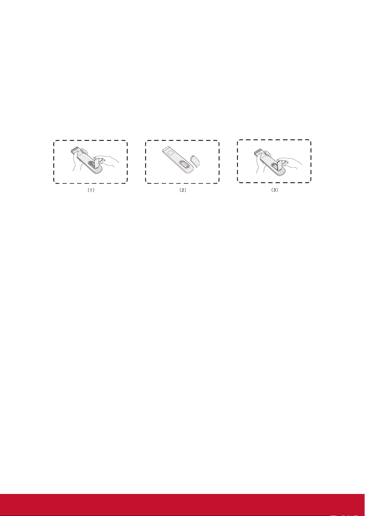
2.4 Inserting Remote Control Batteries
To insert the provided batteries into the remote control follow these instructions. We
recommend that you don’t mix battery types.
1. Remove the cover on the rear of the remote control.
2. Insert two “AAA” batteries, ensuring the “+” symbol on the battery matches the
“+” on the battery post.
3. Replace the cover by aligning it with the slot on the remote control and snapping
the latch shut.
Warning: There is a risk of explosion if batteries are replaced with the incorrect type.
Note: Always dispose of old batteries in an environmentally friendly way. Contact
your local government for more information on how to dispose batteries safely.
7
Page 16
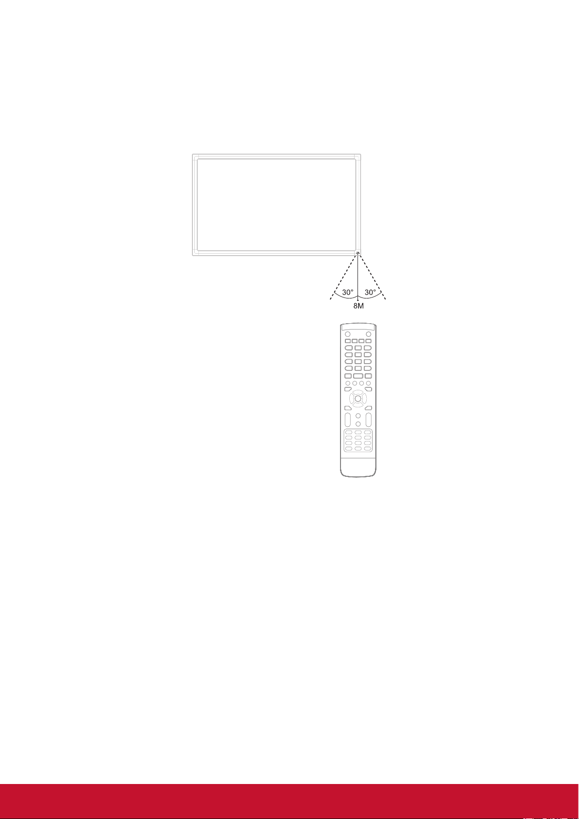
2.5 Remote Control Receiver Range
The working range of the remote control receiver is shown here. It has an effective
range of 8 meters. Make sure there is nothing obstructing the remote control’s signal
to the receiver.
8
Page 17
3. Setting Up Your Display
Warning: For the safety of you and your unit, please do not connect to a power
supply before the external device is prepared.
3.1 Connecting an External Device
1. To display video via VGA cable.
• Connect a VGA cable (15-pin) from your external device to the VGA IN port
on the display.
• Connect an audio cable from the AUDIO OUT port on your external device to
the AUDIO IN port on the display.
• Connect a USB cable to the external device from the TOUCH OUT port of the
display.
HDMI cable
Chromebox
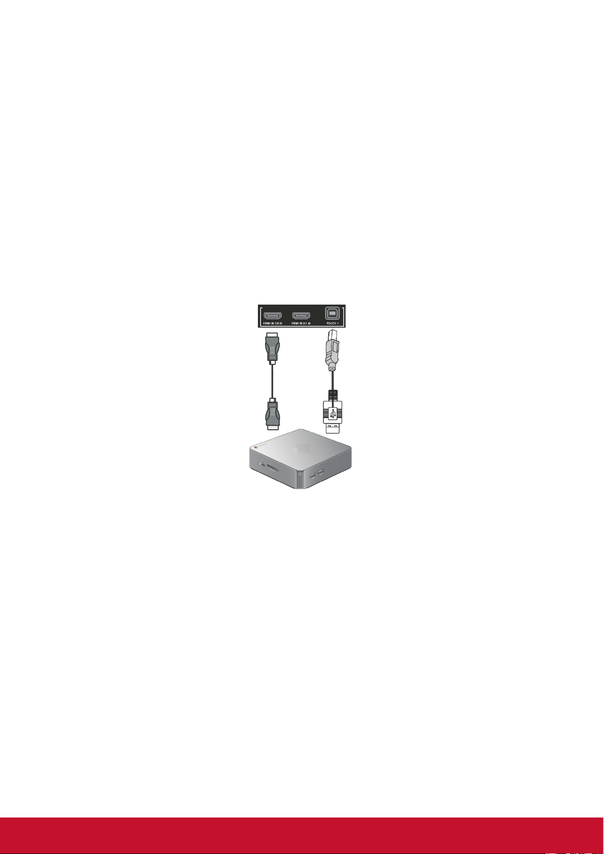
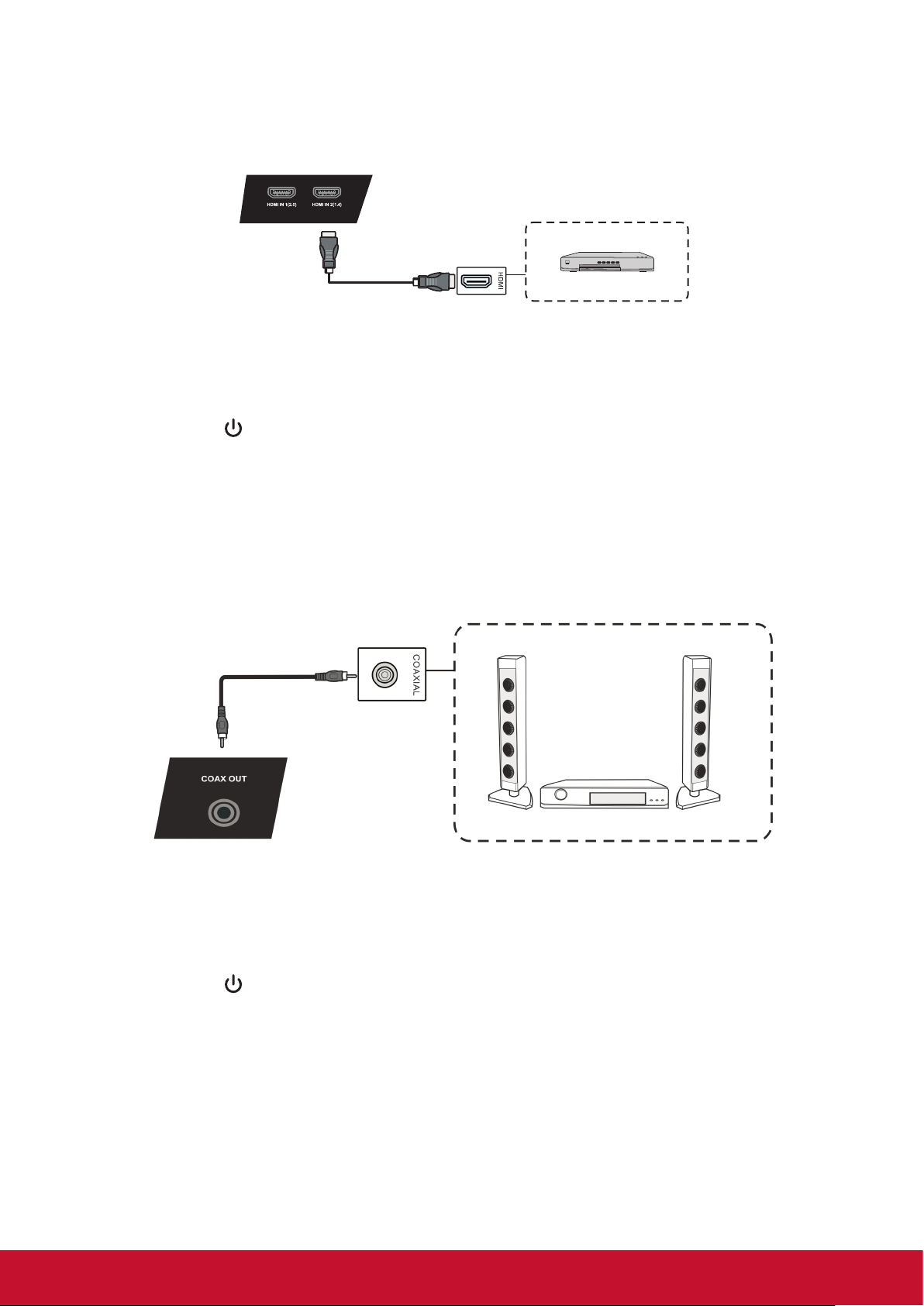
2. To display video via HDMI cable.
• Connect a HDMI cable from your external device to the HDMI IN port on the
display.
• Connect a USB cable to the external device from the TOUCH OUT port of the
display.
USB cable
9
Page 18
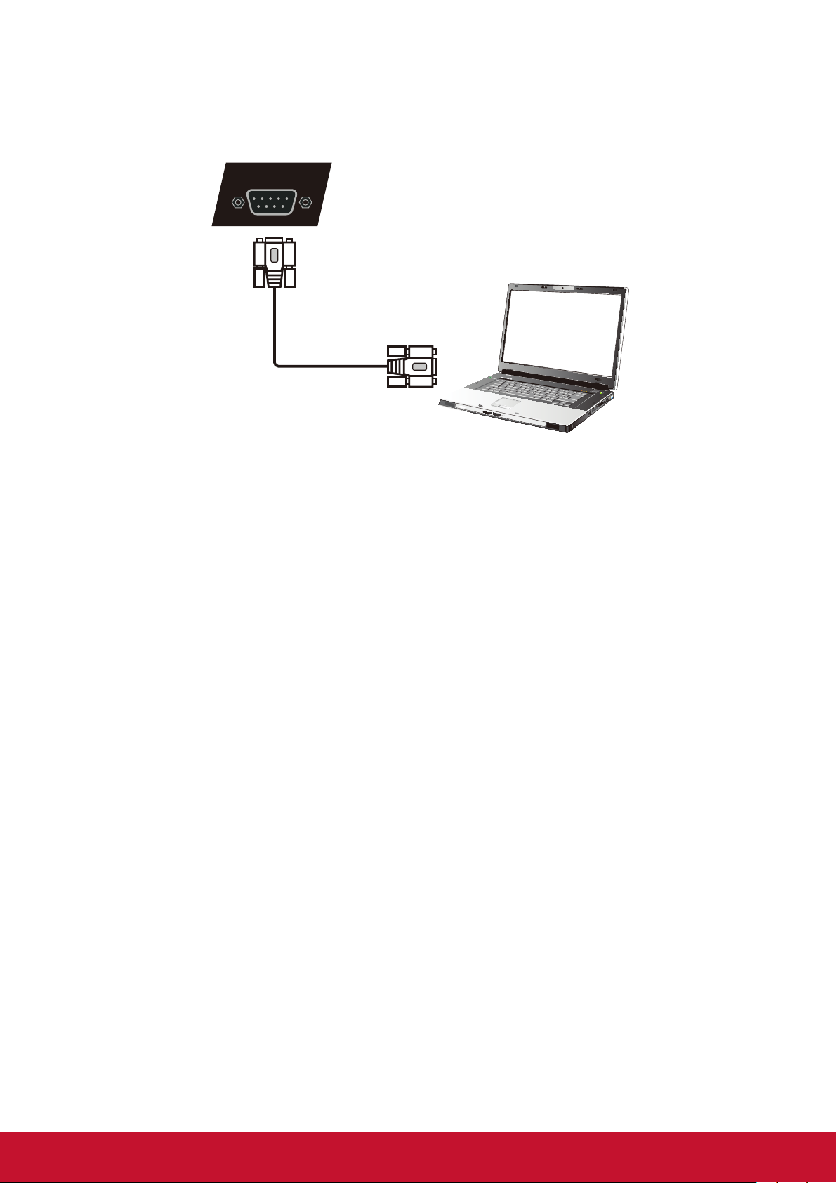
3.2 RS232 Connections
RS232
Serial Port Cable
Computer
When you use a RS232 serial port cable to connect your display to an external
computer, certain functions can be controlled remotely by the PC, including power
on/off, volume adjustment and more.
ViewSonic offer a complimentary software, vConroller, that integrated the common
control comments that user could perform from remote PC to control the ViewSonic
commercial displays. Please find more introduction about control commends via
series port in Chapter 10.
10
Page 19
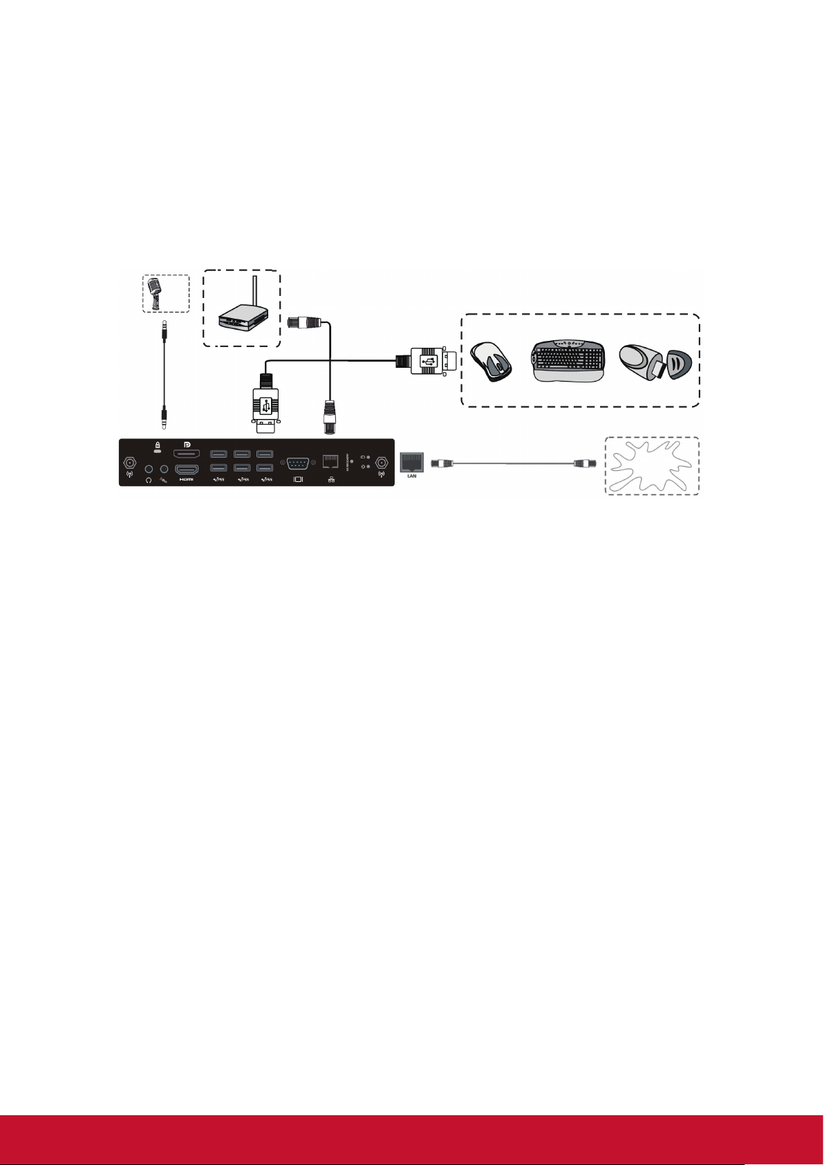
3.3 Connecting USB Peripherals
8
Connecting USB Peripherals
More OSD settings
11
1. USB Peripherals: Plug the USB device cable into the USB IN port.
2. Networking and modem cables: Plug the router cable into the LAN IN port.
3. Microphone: Plug the microphone cable into the MIC port.
Audio Setting Screen Setting Display Setting
Just like a regular PC, it is easy to connect various USB devices and other
peripherals with your smart whiteboard.
1. USB Peripherals: Plug the USB device cable into the USB IN port.
2. Networking and modem cables: Plug the router cable into the LAN IN port.
3. Microphone: Plug the microphone cable into the MIC port.
Router and other
network signal
output
USB cable
Audio cable
Network cable
USB equipment
Network cable
Internet
11
Page 20
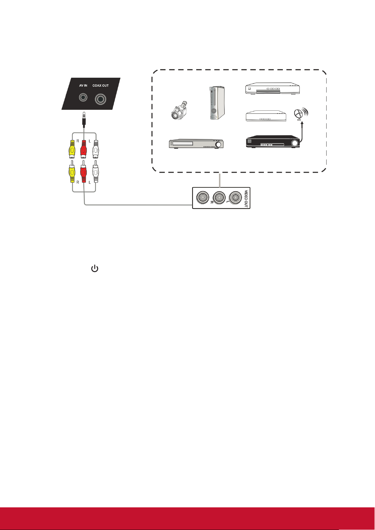
3.4 AV IN Connections
DVD
Set-top
Satellite TV receiver
Video
Video
Camera
Video recorder
Video game
1. Connect a 3-color AV cable from the AV IN ports on your display to the AV OUT
ports of a peripheral device (AV cable: Yellow is Video, Red is Audio-R, White is
Audio-L).
2. Plug in the power cord, and turn on the rear-panel power supply switch.
3. Press the button on the right-hand side of the display to turn the screen on.
4. Press the INPUT button to switch to the “AV” source.
12
Page 21
3.5 Connecting to a media player
Connecting USB Peripherals
HDMI Connections
More OSD settings
11
12
vPen
1. USB Peripherals: Plug the USB device cable into the USB IN port.
2. Networking and modem cables: Plug the router cable into the LAN IN port.
3. Microphone: Plug the microphone cable into the MIC port.
1. In any input source, you can call up the annotation menu by placing two fingers
on the screen (about 20-50mm spacing) and holding there for two seconds.
Audio Setting Screen Setting Display Setting
HDMI cable
1. Connect the HDMI cable to the HDMI ports on your display and peripheral
device.
2. Plug in the power cord, and turn on the rear-panel power supply switch.
3. Press the button on the right-hand side of the display to turn the screen on.
4. Press the INPUT button to switch to the HDMI source.
Note: HDMI 1 supports up to 3840x2160@60Hz
HDMI 2/3 supports up to 3840x2160@30Hz
3.6 Coaxial Connections
Coaxial cable
DVD player
Power amplier/stereo equipment
1. Connect a coaxial cable from DIGITAL OUT to your sound system’s coaxial
connector.
2. Plug in the power cord, and turn on the rear-panel power supply switch.
3. Press the button on the right-hand side of the display to turn the screen on.
13
Page 22
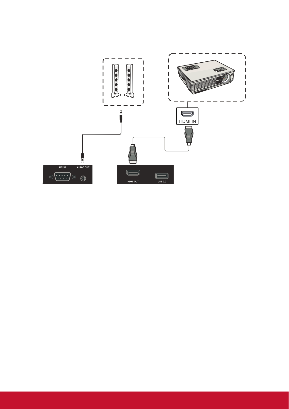
3.7 Video Output Connection
Projector
Audio cable
HDMI cable
1. Use HDMI cable to connect display devices with HDMI in, and use audio cable to
connect sound input.
2. Plug in the power cord, and turn on the rear-panel power supply switch.
3. Press the POEWR button on the right-hand side of the display to turn the screen
on.
Note: The HDMI OUT can output any source signal, and the maximal resolution is
1080P@60Hz.
14
Page 23
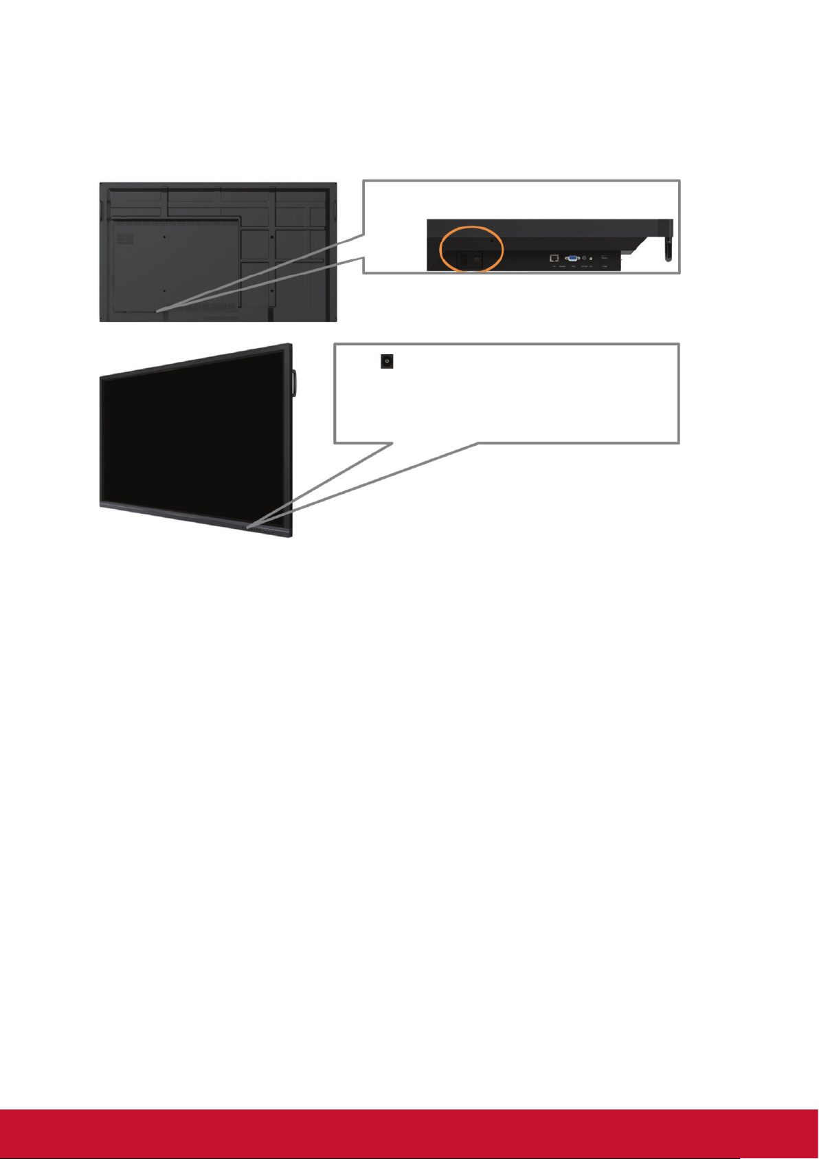
4. ViewBoard Basic Operation
Power on ViewBoard
The AC Power input and switch button located on the
botoom of the unit.
Press
to turn on ViewBoard
15
Page 24
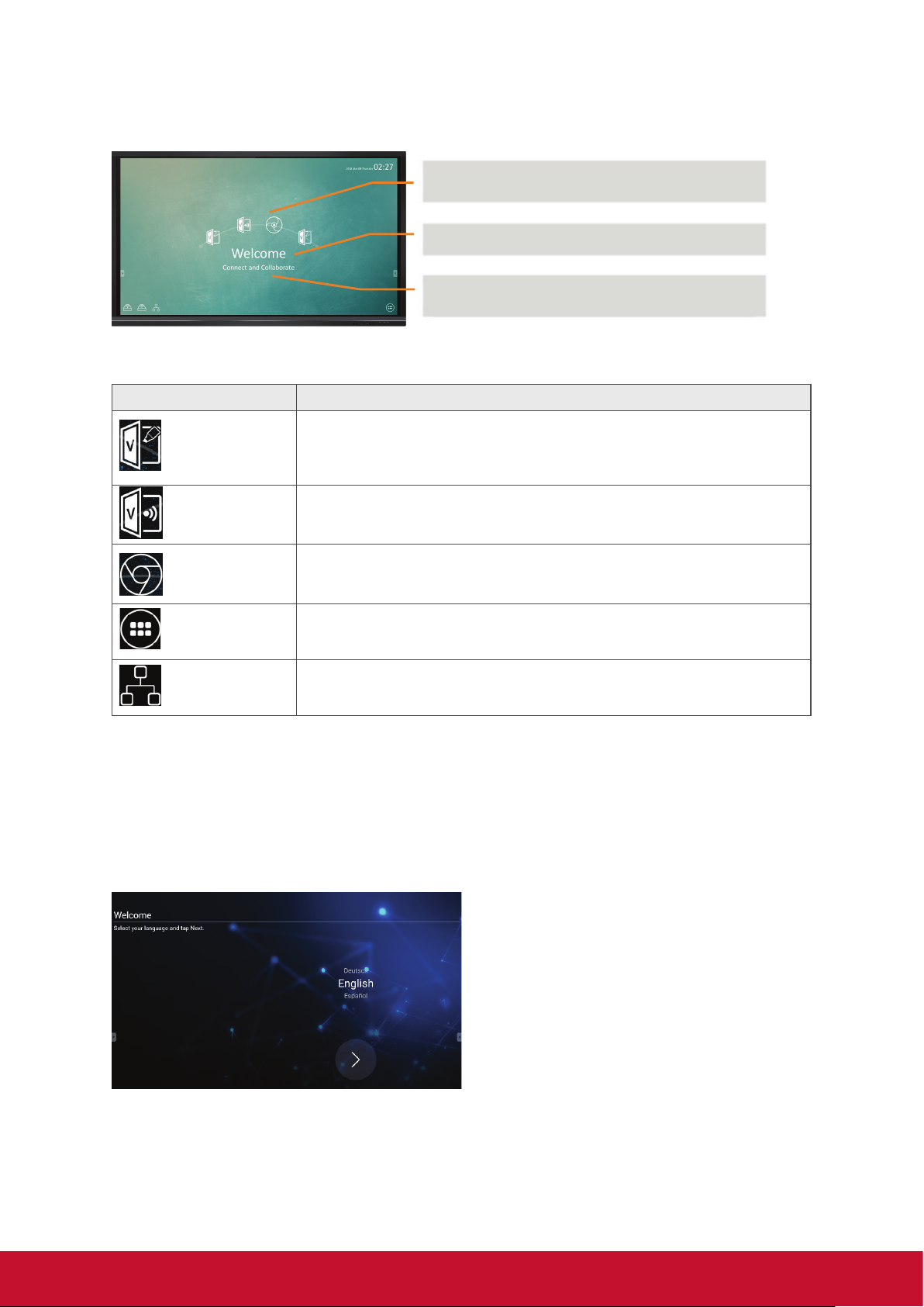
4.1 vLauncher for customized welcome screen
Customizable - choose your “top4“ default app
Editable - change your default message
Switchchable - change your launcher theme
image
Item Description
vBoard
ViewBoard
Cast
Chromium
APPs Click to enter Embedded Player application management page
Network Click to enter Ethernet settings
Click to vBoard software
The icon can be replaced or removed
Click to ViewBoard Cast software
The icon can be replaced or removed
Click to enter internet page
The icon can be replaced or removed
Viewboard will offer two background images design: One with corporate oriented
theme and the other with education oriented theme for user to choose from.
Initial setting for Education mode or Corporate mode
ViewBoard will run setup wizard when user first time to power on it.
Step 1: Select your language.
16
Page 25
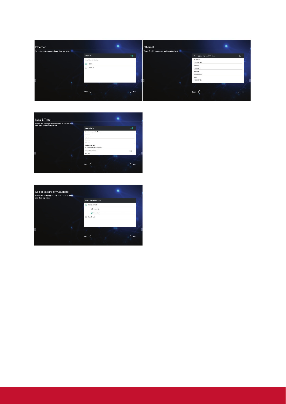
Step 2: To verify LAN connected.
Step 3: Select the appropriate time zone to set the date and time.
Step 4: Select the preferred vBoard or vLauncher mode.
17
Page 26
How to customize the default app:
Step 1:
click the “app“ icon to go to the
app listing page
Step 2:
long press the preferred app icon
e.g. WPS and drag to launcher
page
4.2 Tool Bar
Step 3:
the chosen app e.g. WPS will be
appeared in the launcher as the
short-cut to launch the program
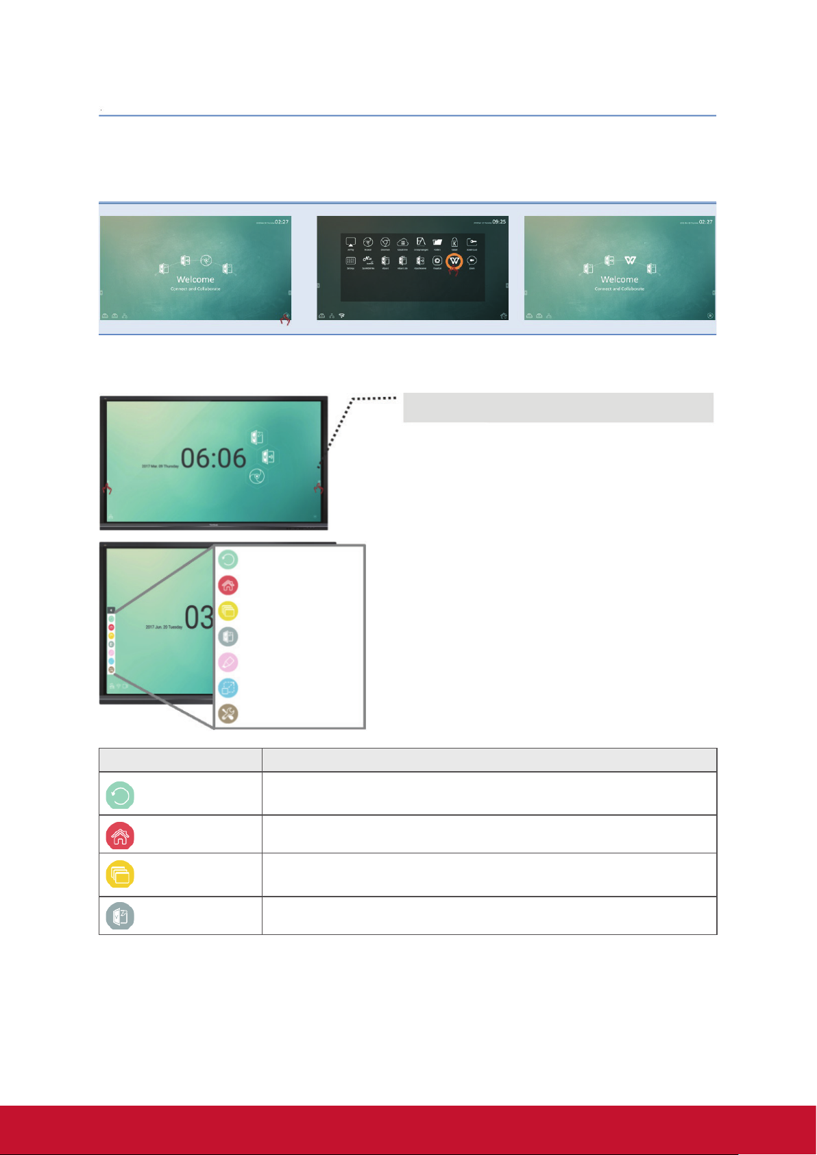
Tool bar trigger icons are in the edge of the ViewBoard
laucher
Click the tool bar icons to pop up the full tools that could facilitate the
interactive usage of ViewBoard. Users could shift the tool bar icon
to the higher or lower position based on dierent usage scenarios.
Default setiings of the tool bar will be available in all input channel
sources; user could go to advanced setting page to change to tool bar
options for below options: (1) available in all channel, (2) available in
all channel but Pc, (3) disable tool bar
Return icon
Home menu
Display all apps in use
Digital whiteboard
Overlay digital pens
Frozen screen
More tools
Item Description
Return
Home Click to return to home interface of Embedded Player.
Display all
vBoard Click to enter vBoard software
Click to return to previous operation interface. (Only for Embedded
Player source)
Click the “display all” icon to display all the embedded app that being
used on this Viewboard
18
Page 27
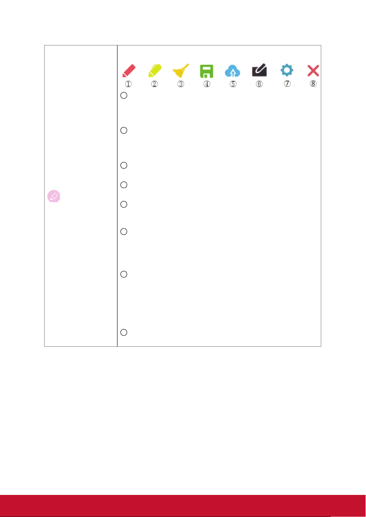
Pen
Click the pen tool icon and pop up the “Pen, Clear, and Save option”
tool bar
1
Digital pen
With four colors options in red, black, blue, and green (rotate in
sequence), that can annotate overlay any input source.
Note: default setting of digital pen supports up to 10-point writing
2
Digital highlighter pen
With the transparency setting and four color options of yellow,
orange, blue, and green (rotate in sequence). Default setting is
10-point marking
3
Brush
Click the “brush icon” to clean all the digital inking on the screen
4
Save as
Click to save the on-screen image into internal storage
5
Cloud drive
Click to save the image into cloud drive. The initial cloud drive
setting is required.
6
Writing mode
Transparent mode: Screen won’t be froze, the screen resolution
won’t be reduce to 1080P.
Opaque mode: Screen will be froze, the screen resolution will be
reduce to 1080P.
7
Picture save
Speed priority: Save the on-screen image to 1920x1080, the save
speed is fast.
Quality priority: Save the on-screen image to 3840x2160, it will
spend around 10 seconds for saving.
Note: In opaque(non-transparent) mode, user can’t select picture
save setting.
8
Close
Click to close the digital pen icon
19
Page 28
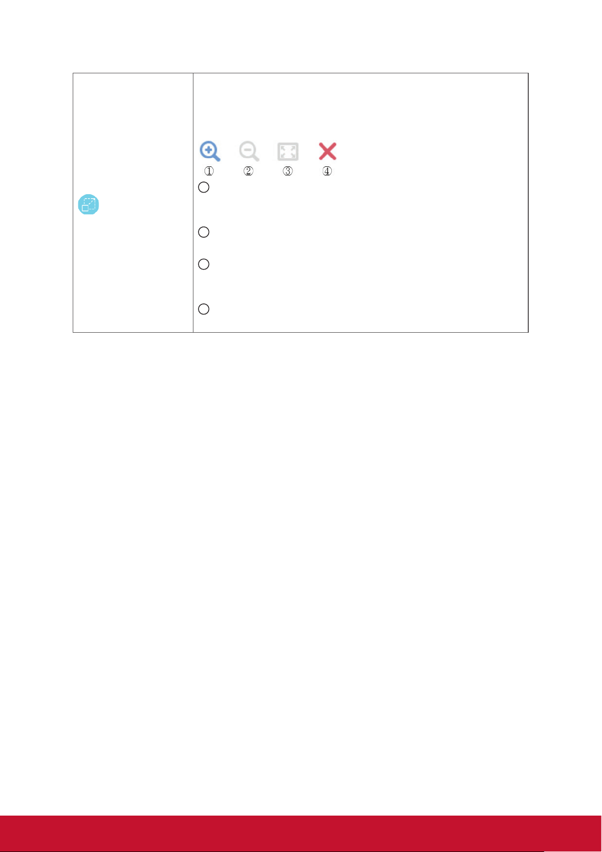
Frozen screen
Click the “Frozen screen” icon to convert the current display content
into a stilled image and then able to zoom in or zoom out for different
discuss usage
Note: IFP will spend 6 seconds to reduce the screen resolution to
1080P.
1
Zoom in
Click to enlarge the “frozen” screen capture image
Note: the screen resolution will be reduced after zoom-in effect
2
Zoom out
Click to shrink the “frozen” screen capture image
3
Back to full screen
Click to reset the room in/ room out effects to the original full
screen
4
Close
Click to close the digital pen icon
20
Page 29
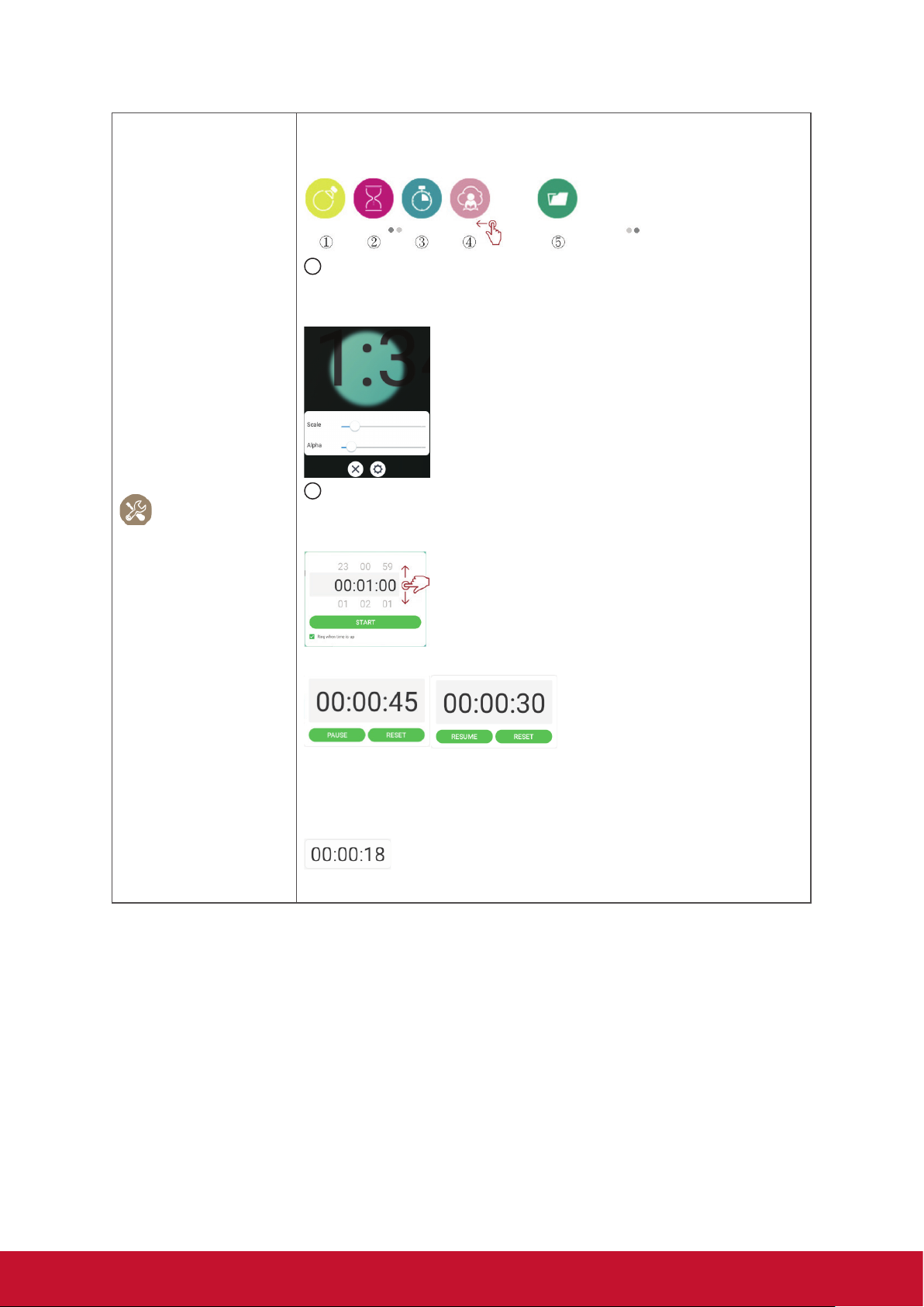
More Tools
Click the “More tools” icon to pop up the more apps within ViewBoard
tool bar. There are 5 tools; touch swipe to show 2nd page of the tool
options.
1
Spotlight
Click to spotlight to highlight the focus content zone. Click the
setting icon to adjust the spotlight size and alpha blending effect.
2
Count down
Click to open the count-down timer, with optional alarm setting.
Touch swipe to adjust the value then click the start icon
User can pause, resume and reset the count-down timer.
Count-down timer will reduce size then move to lower center side
automatically when user touch other area. User just need to click
Count-down timer again, it will return to normal size and original
location.
21
Page 30
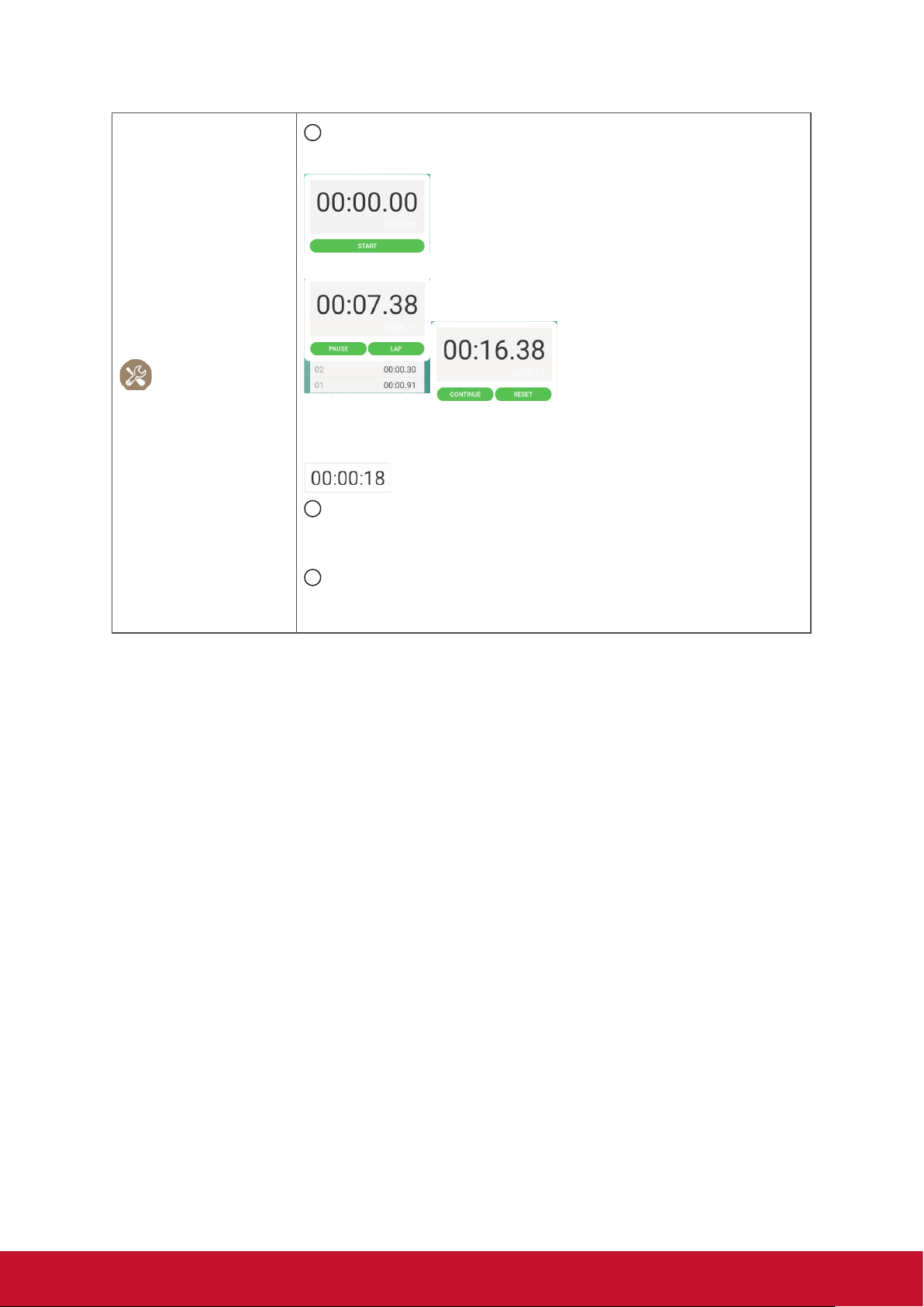
More Tools
3
Stop Watch
Click to open “stop watch” function then click the start icon.
User can pause, continue, reset stop watch and note the figure.
Stop Watch will reduce size then move to lower center side
automatically when user touch other area. User just need to click
Stop Watch again, it will return to normal size and original location.
4
Air Class
Interactive teaching tool for classroom usage. See more
introduction in the chapter 5.3
5
Folder
A short cut to access the folder function and retrieve document.
See more introduction in the chapter 5.4
22
Page 31

4.2.1 vPen
Besides tool bar as the short cut to access for the embedded app; ViewBoard also
have another annotation tool – vPen.
In any input source, to place two fingers on the screen (about 20~50mm spacing)
and stay more than two seconds to call up annotation menu. In this mode, user can
only use touch pen to operate.
Annotation Menu Floating Pen Menu Short cut Menu
Item Description
Annotation menu Pop up sub-menu.
Return Click to return to previous operation interface.
Main Click to return to main interface of Embd Player.
Pen
Screen
capture
Save as
Eraser
Short cut
vBoard
ViewBoard
Cast
Pop up Pen menu.
Click to make annotation in the picture, click again to change color.
Click and drag a rectangle on screen. It can arbitrarily adjust position
and shape of the rectangular.
Storage location: /Storage/vBoard
Click to save the current image to internal storage, Google Drive or
OneDrive.
Internal storage location: /Storage/vBoard
Click to erase handwriting as required.
Pop up short cut menu.
Click to enter vBoard software.
Click to enter ViewBoard Cast software.
App
Close
Click to App interface of Embedded Player.
Click to close annotation menu.
23
Page 32

4.3 ViewBoard OSD (on screen display) Menu
ViewBoard has two options to open up the OSD menu setting:
Option 1: gesture from edge of bottom screen Option 2: click the setting button on the function
keypad
4.3.1 Basic setting
To select an input source:
1. Press INPUT button on remote control to display the general setting menu, then
press DOWN to enter the input source menu..
2. Press DOWN / UP / LEFT/ RIGHT to select the input source you want.
3. Press Enter button on remote control or click with touch pen to select the input
source.
24
Page 33

4. Press BACK key on remote control or click blank area outside menu with touch
pen to quit the on-screen menu.
To adjust the backlight and enable/disable Flicker Free:
1. Press INPUT button on remote control to display the general setting menu.
2. Drag icon directly with touch pen to adjust the backlight value.
3. Click Flicker Free icon to enable/disable the function.
4. Press EXIT key on remote control or click blank area outside menu with touch
pen to quit the on-screen menu.
To adjust the volume:
1. Press INPUT button on remote control to display the general setting menu.
2. Drag icon directly with touch pen to adjust the value.
3. Press < Mute > button on remote control to enable or disable mute function.
4. Press EXIT key on remote control or click blank area outside menu with touch
pen to quit the on-screen menu.
25
Page 34

4.3.2 More OSD settings
Press MENU button (in any source but not Embedded Player source) on remote
control to display general settings menu.
Audio Setting
1. Turn the volume, bass, treble and balance icons directly with touch pen to adjust
value. Or press DOWN / UP / LEFT/ RIGHT to select icon then press VOL+/VOLto adjust value.
2. Click the Standard, Standard, Meeting, Class, Custom icons directly to change
the audio efficacy.
3. Click the Mute icon directly to enable/disable mute function.
26
Page 35

Screen Setting
1. Image Sticking Protection
To reduce the possibility of screen burn, this unit is equipped with image sticking
protection technology.
If the screen displays a still image for a certain period of time you define, the
product activates the screen saver to prevent the formation of burnt in ghost images on the screen.
Image sticking protection moves the picture slightly on the screen.
The image sticking protection Time setting allows you to programmer the time
between movements of the picture in minutes.
Minimize image retention by finely moving pixels horizontally and vertically.
2. Click the 4:3 and 16:9 icons directly to change the ratio.
27
Page 36

Display Setting
1. Turn the Brightness, Contrast, Hue and Sharpness icons directly with touch pen
to adjust value. Or press DOWN / UP / LEFT/ RIGHT to select icon then press
VOL+/VOL- to adjust value.
2. Click the Standard, Bright, Soft and Customer icons to change the display
efficacy.
3. Click the Standard, Cold and Warm icons to change the color temperature.
4. Drag icon directly with touch pen to adjust the blue light value.
Adjust Setting
1. Drag icon directly with touch pen to adjust the value.
2. Click the Auto icon directly to do the auto adjustment.
28
Page 37

4.3.3 Advanced setting
When Viboard in Embd Player source, click advanced setting button in the OSD menu
to enter the advanced setting toward the ViewBoard embedded player.
• Wireless & network: Check the current network connection status and the network
parameters of the device.
Note: WiFi, WiFi hot spot and BT settings will appear when LB-WIFI-001(optional)
has installed.
Ethernet will disable automatically when WiFi is enable.
WiFi will disable automatically when Ethernet is enable.
WiFi will disable when Wireless hotspot is enable.
The device cannot connect to Internet when it connects to Wireless hotspot.
Wi-fi
Click On/Off icon to on/off WiFi function.
29
Page 38

Click more settings to add network, save networks, refresh or entry advanced
setting.
Select a SSID then click connect, user can key in password if needed.
In advanced options, user can set proxy and IP settings.
Ethernet
Click On/Off icon to on/off Ethernet function.
30
Page 39

Click more settings to entry advanced setting.
Click static IP setting to set related settings if needed.
Click Proxy setting to change related settings if needed.
31
Page 40

Wireless hotspot
Click Portable Wi-Fi hotspot icon to on/off Wi-Fi hotspot function.
Click Set up Wi-Fi hotspot to set network name and security then click save.
BT
Click On/Off icon to on/off BT function.
Click more settings to refresh, rename this device and show received files.
32
Page 41

Click a device to pair and connect.
More
Click VPN icon and more icon to always on VPN if needed.
Click + to edit VPN profile.
Click to key in name.
33
Page 42

Click to select type.
Click to enable/disable PPP encryption.
Click to show advanced options.
• Share: SAMBA provides file sharing services in a LAN. When enable the
SAMBA service, user can explore the IFP file system with a PC or mobile
equipment.
34
Page 43

Click to enable SAMBA service then set password if needed.
Connect the IFP and client equipment to the same network. Make sure they are
reachable with each other.
Login the IFP with the client equipment, Windows PC for example. Input the IFP IP
address.
Key in the user name and password then click OK.
35
Page 44

After login success, IFP files will be shown.
• Device: Adjust default home page, wallpaper, HDMI out encryption, Burn-in
Protection Interval.
Home
User can set to different home app.
Note: vBoard and vLauncher can’t be removed.
Display
User can set wallpaper, HDMI out encryption and burn-in protection interval.
36
Page 45

Wallpaper: User can click default image to change the wallpaper directly.
User also can click my photo icon to select the file that user wanted.
37
Page 46

HDMI Out Encryption setting: User can set ON for HDMI signal out or set OFF for
DVI signal out.
Burn-in Protection Interval: The Burn-in Protection Interval setting allows you to
programme the time between movements of the picture in minutes.
Note: The burn-in protection function that in OSD screen setting must enable first.
Storage: Click to check the storage status.
38
Page 47

Click right upper icon to open USB computer connection settings.
Media device (MTP): Let user transfers media files on Windows, or using player file
transfer on Mac.
Camera (PTP): Let user transfers photos using camera software, and transfer any
files on computers that don’t support MTP
Apps
User can see the apps information and to force stop, uninstall, move to USB storage,
clear data, clear cache and clear defaults.
Note: Build in apps can’t be uninstalled.
Not all apps support move to USB storage feature.
Not all apps support clear defaults.
Click right upper icon to sort apps by size, by name and reset app preferences.
39
Page 48

• Personal: The group include security, language & input, startup and shutdown,
password, input setting and other settings.
Security
Trusted credentials: Click to show all CA credentials that IFP has install.
Install from storage: Click to install needed credentials from internal storage or
USB drive.
40
Page 49

Clear credentials: Click to clear installed credentials.
Note: The preloaded credentials can’t be clear.
Unknown sources: Click to enable unknown source function.
Note: User needs to enable unknown source function before install apps.
No guarantee all APK compatible.
Language & inputs: Adjust language and input method of Embedded Player.
Language: Click to select language.
41
Page 50

Current Keyboard: Click to enable/disable visual keyboard or change default input
method.
Existing keyboard: Click to entry advanced settings.
• Startup and shutdown: Set the Startup channel, Standby Mode, Black screen
after startup and On/Off timer.
42
Page 51

Startup channel: Click to change startup channel method.
Built-in PC startup option: Click to change built-in PC startup method.
Standby mode: Click to change standby mode.
Hibernate: To press power button or set power off to turn off IFP, IFP will turn off
all systems.
Sleep: To press power button or set power off to turn off IFP, IFP will turn off
backlight and system still running. If user wants to use LAN RS232 and HDMI
CEC function, the mode can support power on function.
How to enable sleep mode:
1. User needs to provide IFP S/N to ViewSonic. The S/N label is located near
I/O side.
2. ViewSonic will provide the KEY (FakePowerOff) file to user.
3. After getting the KEY file, copy the file to USB drive root.
4. Insert the USB drive to the USB port of IFP. (The KEY file MUST match
the IFP S/N).
5. Select Sleep.
Note: User does not need to restart the system.
If user sets the Standby Mode to Hibernate then set to Sleep again, user
needs to do step 3 to 5 again.
The KEY file must be paired with the specific S/N which is provided by
user as request.
Reminder: When Sleep mode is enabled, the system is still running on standby.
For energy-saving and product reliability assurance, please only
enable Sleep mode when it is necessary to do so.
43
Page 52

Black screen after startup: When the function is enable, IFP will turn off backlight
automatically after boot time schedule.
Close power off reminder: When the function is enable, IFP will turn off directory
without any reminder after off time schedule.
Touch swipe to adjust the value and select day then click
On/off timer:
Click + to add a schedule.
to save.
Touch swipe to adjust the value and select day then click ✓ to save.
• Password: Click to set the screen lock password then click OK to save.
44
Page 53

• Input setting: To enable/disable and edit input alias. To enable/disable Wake
On Active Source, Channel auto switch, Auto search and set No signal power off
timer.
Input alias switch: Click to enable then user can edit input alias.
Wake on active source: When the function enable, IFP will detect HDMI and
VGA signal in standby mode. If HDMI or VGA has signal output, IFP will power
on automatically.
Note: Only HDMI and VGA ports support the function.
Auto search: When the function enable and existing source has no signal, IFP
will search input source automatically one time.
Channel auto switch: When the function enable and IFP detect new signal
input, IFP will switch input source automatically.
No signal power off: Click to adjust no signal power off timer.
45
Page 54

• Other settings: To set vPen, Side Tool Bar channel setting, and vBoard Lite
writing setting.
vPen channel setting: Click to set vPen available channel.
Side toolbar channel setting: Click to set side toolbar available channel.
vBoard Lite writing: Click to change the vBoard Lite touch function for single or
multi finger.
• Date & time: Set the system time and format.
Automatic date & time: When the function enable, IFP will synchronize date
and time with Internet.
Note: The Ethernet or WiFi connection needed.
Set date: Touch swipe to adjust the value then click OK to save.
46
Page 55

Set time: Touch swipe to adjust the value then click OK to save.
Select time zone: Click to select different time zone.
Select time format: Click to select different time format.
Choose date format: Click to choose different date format.
47
Page 56

• Device information: Display Embedded Player information, system updates and
display ID setting.
System update: Click to upgrade firmware via OTA.
Legal information: Click to check the open source licenses
Display ID: Click to change display ID then click OK to save.
Note: The display ID is for RS232 uses.
The display ID range is 01~98.
48
Page 57

5. ViewBoard Embedded Application
and Setting
5.1 Embedded Digital Whiteboard App
Within ViewBoard, Viewsonic offers two version of the embedded digital whiteboard
app for users to choose and annotate.
5.1.1 vBoard
vBoard user interface:
• Click to open up the setting window.
(1) Brightness adjustment
(2) Background color adjustment
49
Page 58

(3) Volume adjustment
(4) More setting option: Quick link to the embedded player setting, vBoard
supports 10-point writing by default user could go the setting mode and switch
back to single point writing.
(5) Information “about” this vBoard.
• Pen: click
Select pen thickness and type
Change pen color
to open more pen option.
Tool to draw line and different shapes
50
Page 59

• Open Document: click
Click to view document directory
Select document in vBoard format
to open document and content files
Import video into vBoard
Import audio into vBoard
Import image file into vBoard
51
Page 60

• Page: click
Click to add one more page
Click to delete one page
to conduct page management
Click the page to move to
5.1.2 vBoard Lite
vBoard Lite user interface:
Menu function setting
52
Page 61

New Click to create new file
Open Click to open *.enb format file
Import Click to import *.jpg format file
Save
Export Click to export c urrent content
Cloudy
Storage
Background
Auto
brightness
Click to save current content to *.enb
format
Click to upload the current image to cloud
storage.
Click to change background
Click to enable/disable auto brightness
Watercolor – another annotation tool option within vBoard lite
53
Page 62

Watercolor
Item Description
Pen
Thickness Click to change thickness
Palette
Dipper Click dipper to dip up color for pen
Color disc Click to change pen color
Click to select different type
Note: In pen mode, it supports up to 10 points for writing
Select color then press and rotate the circle on palette to adjust color
54
Page 63

5.2 ViewBoard Cast
ViewBoard Cast is the built-in wireless screen sharing receiver app within ViewBoard
that allow users to cast in their presentation content, including mirroring screen content, images, videos, and audios. Before use ViewBoard Cast function, please be
noted that proper network infrastructure setting is required.
ViewBoard Cast is the wireless peer to peer data communication so that a proper
ports setting is required.
Ports:
- TCP: 56789, 25123, 8121, and 8000 ports
- UDP: 48689, 25123
Port for activation:
- Port: 8001
[Remark] please be noted that screen sharing or video casting in/out is highly
defendant on the each school’s or corporate’s IT network configuration and WiFi
network bandwidth. The variation might be cause from internal network speed,
routing, WiFi configuration, and QoS setting. Please consult your IT for related
details.
55
Page 64

5.2.1 Cast sender from Windows-based devices, Macbook, and Chrome
devices
Mac, Windows and Chrome devices
1. Make sure your device is connected to the same network with IFP.
2. Visit the address that shown on IFP to download application.
3. Launch ViewBoard Cast and click the icon number that shown on IFP.
56
Page 65

5.2.2 Viewboard Cast sender from mobile devices: iOS-based (iPhone, iPad)
and Android OS based phone/tablet
iOS
Step 1: Make sure your device is connected to the same network with IFP.
Step 2: Enter password that shown on IFP.
Step 3: Slide up at the bottom enter the quick set Open AirPlay.
Step 4: Select the device, then the iOS operate interface will appear.
Android
Step 1: Make sure your device is connected to the same network with IFP.
Step 2: Enter password that shown on IFP.
Step 3: Scan the QR code that shown on IFP to download the client.
Step 4: Open the ViewBoard Cast client.
57
Page 66

5.2.3 ViewBoard Cast out from mobile device will support annotation function
Item Description
Toggle Click to hide or display tool bar
Home Click to return to home interface
Return Click to return to previous operation interface
Folder Click to view or open mobile device internal file
Screen
sharing
Touch Click to change to touch mode
Pen
Clear Click to clean all the elements
Click to share screen
(Android 5.0 above supported)
Click to make annotation in the picture
Click to change color or thickness
Camera Click to use camera then send the image to IFP50
58
Page 67

5.3 Air Class
Display quiz questions on ViewBoard® and allow up to 30 mobile users to submit answers remotely. Whether deploying single or multiple choice questions, ViewBoard®
will record statistic result for each device being used.
Network information
PC (Window/ Mac/ Chromebook) and tablet/ mobile (iOS/Android) devices, as well
as ViewBoard® need to link to the same LAN network subnet.
Ports : TCP 8080
Click “Enter Air Class” on ViewBoard and select one interactive function to open up
Air Class interface
59
Page 68

Voter
Click
to define answer type.
Click BEGIN icon let participant starts answer.
After participant presses OK icon to done the answer, the IFP will show the
participant‘s name on screen.
icon to enter Voter interface. Click “Single choice” or “Multiple choice” icon
Click Finish icon to done the vote, then Answer statistics will be displayed.
Choose the right answer to show the correct rate.
60
Page 69

Click icon to analyze.
61
Page 70

Responder
Click
Message
Click
Message operation
to enter Responder. Participant needs click OK icon to answer.
to enable/disable message function.
1. Click Message icon to enable the function.
2. Participant clicks Message icon the change to Message interface.
3. Participant key in message then click Send icon.
4. The message will appear on IFP50 upper side.
Manager
Click
Exit
Click
to appear QR code to let more participants join the class.
to exit class interface.
62
Page 71

5.4 Other default apps
Zoom
Click
to run Zoom application.
1. Click Sign In. Enter your email and password or sign in with your Google,
Facebook or SSO account.
2. If you do not have a Zoom account, you should select Sign Up.
63
Page 72

Join a Meeting
1. Select Join a Meeting.
2. Enter the Meeting ID of the meeting you want to join.
3. Click Join Meeting.
64
Page 73

Start an Instant Meeting
1. Select Schedule or Host a Meeting.
2. Choose the meeting options:
• Choose to have Video On or off.
• Choose to Use Personal Meeting ID or a unique meeting ID.
3. Click Start a Meeting.
4. Invite meeting participants by clicking the Participants icon at the bottom of the
screen.
5. Click Invite at the bottom of the Participants screen.
6. Select the participants using the contact method you want to use for inviting
participants.
65
Page 74

Visualizer
Click
to run Visualizer application.
Item Description
Exit Click to exit
Resolution
setting
Pen Click to make annotation in the picture
Screen shot Click to screen shot
Adjustable
mode
Full screen Click to show as full screen
Click to change camera resolution
In this mode, user can use two fingers to zoon in/out and rotate the image
66
Page 75

Keeper
Click
to run Keeper application.
Item Description
One Key
Optimize
memory
clean
Garbage
clean
Information Click to check the system information
Exit Click to exit
Click to optimize the system, memory clean and garbage
clean
Click to memory clean
Click to garbage clean
67
Page 76

Screen Lock
Click
Note: If user forgets the password, to press remote control INPUT 0214 fast to
restore the password to default.
Set password
Screen lock enabled
to set screen lock password or enable screen lock.
68
Page 77

Browser
Enter web browser to surfing the internet.
Folders
1. Storage device display: Click with touching pen to enter corresponding storage
devices area.
2. Icons:
Item Description
Exit
Sort
Thumbnail
List
Click to exit.
Click to sort file.
Click to display file by thumbnail mode.
Click to display file by list mode.
69
Page 78

Select
Click to select file.
Add folder
Copy
Paste
Cut
Delete
Rename
More
Click to add folder.
Click to copy file.
Click to paste file.
Click to cut file.
Click to delete file.
Click to rename file.
Click to show more functions.
3. File type menu:
All: All types
Doc: OFFICE type files
Note: Image stored by vBoard Lite, Side Tool Bar and remote control Screen
capture button.
Picture: Image type files
Media: Audio and video type files
4. File information: To preview the image, show the image’s name, size, resolution
and created date.
5. Main display area: Display files of corresponding type.
70
Page 79

Cloud Drive
Item Description
Add Account Add user account.
Use the default account
Use the default file name
when save
You will be logged out
after n minutes
The current image will be uploaded to cloud storage without
confirm account again after press upload icon.
The current image will be uploaded to cloud storage without editing
file name after press upload icon.
System will log out cloud drive automatically.
71
Page 80

6. Trouble Shooting
Remote control is out of
order
The unit turns of unexpectedly
PC mode
No PC signal 1. Check the display settings.
Background streaking 1. Choose auto adjust.
1. Check whether something is obstructing the
display’s remote control receiver.
2. Check whether the batteries in the remote control
are installed correctly.
3. Check whether the batteries need to be replaced.
1. Check whether Sleep mode is enabled.
2. Check if there is a power outage in your area.
3. Turn on the display and see if the problem is with
the signal and control system.
2. Check the display resolution.
3. Adjust the Hs & Vs (synchronization) settings using
the OSD menu.
2. Adjust clock and phase.
False color 1. Check the VGA connection.
2. Adjust chroma, brightness and contrast settings.
Unsupported format 1. Choose auto adjust.
2. Adjust clock and phase settings.
Touch Function
Touch function does not
work
1. Check that drivers are installed correctly.
2. Reinstall driver.
3. Check setup and align it.
4. Check whether the touch pen is working properly.
72
Page 81

Video not working properly
No picture / No sound 1. Check POWER status.
2. Check the signal cable.
3. Check that the internal PC is installed correctly.
Picture trembling 1. Check the signal cable.
2. Check if other electronics are interrupting the
signal.
Poor picture 1. Adjust chroma, brightness and contrast settings in
the menu.
2. Check the signal cable.
Audio not working properly
No sound 1. Press the Mute/ Unmute button.
2. Adjust the volume.
3. Check the audio cable.
One speaker only 1. Adjust the sound balance in the menu.
2. Check the sound control panel settings of the
computer.
3. Check the audio cable.
73
Page 82

7. Care and Maintenance
Please follow these cleaning guidelines to make sure your smart whiteboard display
looks like new for years to come:
• Don't clean the machine if it has been turned on for a long period of time.
• Unplug the unit from the wall outlet before cleaning or polishing it.
• Don’t use liquid cleaners or aerosol cleaners on the screen.
• Only use a slightly dampened cloth when cleaning the exterior of the unit.
• Don't use system continuously for long periods of time.
• Remember to unplug the display when it is not in use.
• Use a power surge protector to prevent system failures and power supply surges.
• Make sure the display remains dry at all times. Be careful when handling liquids
near or on the unit.
Note: If condensation appears between the glass and the panel, keep the display
turned on until the moisture disappears.
74
Page 83

8. Display Modes
8.1 VGA Mode
640x480 @60Hz/72Hz/75Hz
720x400 @70Hz
800x600 @56Hz/60Hz/72Hz/75Hz
832x624 @75Hz
1024x768 @60Hz/70Hz/75Hz
1152x864 @60Hz/75Hz
1152x870 @75Hz
1280x768 @60Hz/75Hz
1280x960 @60Hz
1280x1024 @60Hz/75Hz
1360x768 @60Hz
1366x768 @60Hz
1440x900 @60Hz/75Hz
1400x1050 @60Hz/75Hz
1600x1200 @60Hz
1680x1050 @60Hz
1920x1080 @60Hz
1920x1200 @60Hz
75
Page 84

8.2 HDMI Mode
640x480 @60Hz/72Hz
720x400 @70Hz
800x600 @60Hz/72Hz
1024x768 @60Hz/70Hz/75Hz
1280x800 @60Hz
1280x1024 @60Hz
1360x768 @60Hz
1440x900 @60Hz
1680x1050 @60Hz
1920x1080 @60Hz
3840x2160
480i @60Hz
480p @59Hz/60Hz
576i @50Hz
720p @50Hz/60Hz
576p @50Hz
1080i @50Hz/60Hz
1080p @50Hz/60Hz
@30Hz (HDMI 2/3)
@60Hz (HDMI 1)
76
Page 85

8.3 DP Mode
640x480 @60Hz/72Hz
720x400 @70Hz
800x600 @60Hz/72Hz
1024x768 @60Hz/70Hz/75Hz
1280x800 @60Hz
1280x1024 @60Hz
1360x768 @60Hz
1440x900 @60Hz
1680x1050 @60Hz
1920x1080 @60Hz
3840x2160 @30Hz
480i @60Hz
480p @59Hz/60Hz
576i @50Hz
720p @50Hz/60Hz
576p @50Hz
1080i @50Hz/60Hz
1080p @50Hz/60Hz
77
Page 86

9. Specications
Model
Screen Size
Input Signal
Output Signal
Speaker Output
RS232
Power Voltage
Operation
Conditions
Temperature
Humidity
Altitude
Storage
Conditions
Temperature
Humidity
Altitude
IFP5550 IFP6550 IFP7550 IFP8650
54.6” 64.5” 74.5” 85.6”
3 x HDMI
1 x DP
1 x VGA
1 x PC audio
1 x CVBS
1 x HDMI
1 x Earphone
1 x SPDIF(coaxial)
16W x 2
RS232 communication
100V-240V AC 50/60HZ
32°F to 104°F (0°C to 40°C)
20% ~ 80% non-condensing
≦2000M
-4°F to 140°F (-20°C to 60°C)
10% ~ 90% non-condensing
≦2000M
Dimensions Physical (mm)
Weight Physical (kg)
Power
Consumption
On
Off
1302 x 799 x 98 1521 x 922 x 99 1763 x 1042
x 99
34 47 58.5 78
129W
<0.5W
350W
<0.5W
430W
<0.5W
Note: Product Specifications are subject to change without notice.
1988 x 100 x
1186
500W
<0.5W
78
Page 87

10. RS-232 Protocol
10.1 Introduction
This document describes the hardware interface spec and software protocols of
RS232 interface communication between ViewSonic LFD and PC or other control
unit with RS232 protocol.
The protocol contains three sections command:
• Set-Function
• Get-Function
• Remote control pass-through mode
※ In the document below, “PC” represents all the control units that can sent or
receive the RS232 protocol command.
10.2 Description
10.2.1 Hardware Specication
ViewSonic LFD communication port on the rear side
(1) Connector type: DSUB 9-Pin Male (or 3.5mm barrel connector)
(2) Pin Assignment
(3) Use of crossover (null modem) cable for connection
Male DSUB 9-Pin
3.5mm barrel connector
(alternative for limited
space)
Pin # Signal Remark
1 NC
2 RXD Input to Display
3 TXD Output from Display
4 NC
5 GND
6 NC
7 NC
8 NC
9 NC
frame GND
Pin # Signal Remark
Tip TXD Output from Display
Ring RXD Input to Display
Sleeve GND
79
Page 88

10.2.2 LAN Hardware Specication
ViewSonic LFD communication port on the rear side
(1) Connector type: 8P8C RJ45
(2) Pin Assignment
Pin # Signal Remark
1 TX+ Output from Display
2 TX- Output from Display
3 RX+ Input to Display
4 BI_D3+ For 1G case
5 BI_D3- For 1G case
6 RX- Input to Display
7 BI_D4+ For 1G case
8 BI_D4- For 1G case
frame GND
10.2.3 RS232 Communication Setting
- Baud Rate Select: 9600bps (fixed)
- Data bits: 8 bits (fixed)
- Parity: None (fixed)
- Stop Bits: 1(fixed)
10.2.4 LAN Communication Setting
- Type: Ethernet
- Protocol: TCP/IP
- Port: 5000 (fixed)
- Cross subnet: No
- Logon Credentials: No
10.2.5 Command Message Reference
PC sends to LFD command packet followed by “CR”. Every time PC sends control
command to Display, the Display shall respond as follows:
1. If the message is received correctly it will send “+” (02Bh) followed by “CR”
(00Dh)
2. If the message is received incorrectly it will send “-” (02Dh) followed by “CR”
(00Dh)
80
Page 89

10.3 Protocol
10.3.1 Set-Function Listing
The PC can control the Display for specific actions. The Set-Function command
allows you to control the Display behavior in a remote site through the RS232 port.
The Set-Function packet format consists of 9 bytes.
Set-Function description:
Length: Total Byte of Message excluding “CR”
LFD ID Identification for each of Display (01~98; default is 01)
ID “99” means to apply the set command for all connected
displays. Under such circumstances, only ID#1 display has to
reply.
The LFD ID can be set via the OSD menu for each Display.
Command Type Identify command type,
“s” (0x73h): Set Command
“+” (0x2Bh): Valid command Reply
“-“ (0x2Dh): Invalid command Reply
Command: Function command code: One byte ASCII code.
Value[1~3]: Three bytes ASCII that defines the value.
CR 0x0D
81
Page 90

Set-Function format
Send: (Command Type=”s”)
Name Length ID Command
Type
Byte
Count
Bytes
order
Reply: (Command Type=”+” or “-”)
Name Length ID Command
Byte
Count
Bytes
order
NOTE:
1. When PC applies command to all displays (ID=99), only the #1 set needs to reply
by the name of ID=1.
1 Byte 2 Byte 1 Byte 1 Byte 1 Byte 1 Byte 1 Byte 1 Byte
1 2~3 4 5 6 7 8 9
1 Byte 2 Byte 1 Byte 1 Byte
1 2~3 4 5
Command Value1 Value2 Value3 CR
CR
Type
Example1: Set Brightness as 76 for Display (#02) and this command is valid
Send (Hex Format)
Name Length ID Command
Type
Hex
Reply (Hex Format)
Name Length ID Command
Hex
Example2: Set Brightness as 75 for Display (#02) and this command is NOT
valid
Name Length ID Command
Hex
0x38 0x30
0x32
0x34 0x30
0x38 0x30
0x32
0x73 0x24 0x30 0x37 0x36 0x0D
0x32
Type
0x73 0x24 0x30 0x37 0x35 0x0D
Command Value1 Value2 Value3 CR
CR
Type
0x2B 0x0D
Command Value1 Value2 Value3 CR
82
Page 91

Reply (Hex Format)
Name Length ID Command
CR
Type
Hex
0x34 0x30
0x2D 0x0D
0x32
Set-function table
A. Basic function
Set
Function
Power on/ off
(standby)
Input Select 8 s “ 22 000: TV
Length ID Command Command Value Range Comments
Type
(ASCII)
8 s ! 21 000: STBY
Code (ASCII) Code (Hex) (Three ASCII bytes)
001: ON
001: AV
002: S-Video
003: YPbPr
004: HDMI1
014: HDMI2
024: HDMI3
034: HDMI4
The Power-on via LAN
control may works only
under specific mode.
To see display UG for
details. *3.1.1
1. No need for USB
2. For the case of two
more same sources, the
2nd digital is used to
indicate the extension.
3. The HEX of 00A is 30
30 41.
005: DVI
006: VGA1
016: VGA2
026: VGA3
007: Slot-in PC
(OPS/SDM)/HDBT
008: Internal
memory
009: DP
00A: Embedded/
Main (Android)
Brightness 8 s $ 24 000 ~ 100
900: Bright down
(-1)
901: Bright up (+1)
*3.1.1
Power lock 8 s 4 34 000: Unlock
001: Lock
Volume 8 s 5 35 000 ~ 100
900: Volume
down(-1)
901:Volume up(+1)
Mute 8 s 6 36 000: OFF
001: ON (mute)
Button lock 8 s 8 38 000: Unlock
001: Lock
Menu lock 8 s > 000: Unlock
001: Lock
*See note in details
*See note in details
*See note in details
83
Page 92

Number *3.1.1 8 s @ 40 000~009
Key Pad
Remote
Control
Restore
default
*3.1.1 8 s A 41 000: UP
8 s B 42 000: Disable
8 s ~ 7E 000 Recover to factory set-
NOTE:
1. Behavior at lock modes
Lock Mode Behavior
001: DOWN
002: LEFT
003: RIGHT
004: ENTER
005: INPUT
006: MENU/(EXIT)
007: EXIT
001: Enable
002: Pass through
Disable: RCU will be no
function
Enabled: RCU controls
normally
Pass through: Display
will bypass the RC code
to connected device via
the RS232 port, but not
react itself.
ting
Button Lock 1. Lock all buttons on the front panel and RCU, except for
“Power”
2. All the SET functions should be workable via RS32, even the
ones with according hot key in RCU like Mute,…etc.
MENU Lock 1. Lock “MENU’ key of front panel and RCU
2. The Factory and Hospitality modes should not be blocked
for the model using MENU-combined key to enter these two
modes. Alternative approach will be indicated separately if
any limitation by model.
POWER Lock 1. Lock “POWER” key on the front and RCU.
2. The SET_POWER on/off should be workable via RS232, but
does not mean the POWER lock will be released under this
case.
3. Can not be unlocked by reset in OSD setting
4. Will auto AC power-on in power-lock
5. Under power-lock, the set will not enter power saving when
no PC signal and neither not turn off when no other video
signals after 15min.
Remote control
Lock the RCU keys, but keep the front panel buttons workable.
disable
84
Page 93

B. Optional function
Set
Function
Contrast 8 s # 23 000 ~ 100
Sharpness 8 s % 25 000 ~ 100
Color 8 s & 26 000 ~ 100
Tint 8 s ‘ 27 000 ~ 100
Color mode 8 s ) 29 000: Normal
Surround
sound
Bass 8 s . 2E 000 ~ 100
Treble
Balance 8 s 0 30 000 ~ 100 050 is central
Picture Size 8 s 1 31 000: FULL (16:9)
OSD language
PIP-Mode 8 s 9 39 000: OFF
PIP-Sound
select
PIP-Position 8 s ; 3B 000: Up
PIP-Input 8 s 7 37
Length ID Command Command Value Range Comments
Type
(ASCII)
8 s - 2D 000: OFF
8 s
8 s 2 32 000: English
8 s : 3A 000: Main
Code (ASCII) Code (Hex) (Three ASCII bytes)
001: Warm
002: Cold
003: Personal
001: ON
/ 2F 000 ~ 100
001: NORMAL (4:3)
002: REAL (1:1)
*3.1.0
001: French
002: Spanish
001: PIP(POP)
002: PBP
001: Sub
001: Down
002: Left
003: Right
*2.9 000: TV
001: AV
002: S-Video
003: YPbPr
004: HDMI1
014: HDMI2
024: HDMI3
034: HDMI4
Could be extended for
more supported languages by model
Value range is same as
SET-Input select
85
005: DVI
006: VGA1
016: VGA2
026: VGA3
007: Slot-in PC
(OPS/SDM)/HDBT
008: Internal
memory
009: DP
00A: Embedded/
Main (Android)
Page 94

Tiling-Mode 8 s P 50 000: OFF
001: ON
(for video wall)
Tiling-Compensation
Tiling-H by V
Monitors
Tiling-Position
Date: Year 8 s V 56 Y17~Y99 Last 2 digits
Date: Month 8 s V 56 M01~M12 2 digits
Date: Day 8 s V 56 D01~D31 2 digits
Time: Hour 8 s W 57 H00~H23 24-hr format. 2 digits.
Time: Min 8 s W 57 M00~M59 2 digits
Time: Sec 8 s W 57 S00~S59 2 digits
8 s Q 51 000: OFF
001: ON
8 s R 52 01x~09x: H
0x1~0x9: V
8 s S 53 001~025 (for Video wall)
(for video wall)
Bezel width compensation
(for video wall)
1. 2nd digital for H
monitors
2. 3rd digital for V monitors
Copy the screen of
Position# to identified
display
(20)17~(20)99
Note:
1. Tiling definition of H Monitors/ V Monitors/ and Position
2. Set Date example
Date: 2017-3/15
Send: 0x 38 30 31 73 56 59 31 37 0D (“Y17”)
Send: 0x 38 30 31 73 56 4D 30 33 0D (“M03”)
Send: 0x 38 30 31 73 56 44 31 35 0D (“D15”)
86
Page 95

3. Set Time example
Time: 16:27:59
Send: 0x 38 30 31 73 57 48 31 36 0D (“H16”)
Send: 0x 38 30 31 73 57 4D 32 37 0D (“M27”)
Send: 0x 38 30 31 73 57 53 35 39 0D (“S59”)
10.3.2 Get-Function Listing
The PC can interrogate the LFD for specific information. The Get-Function packet
format consists of 9 bytes which is similar to the Set-Function packet structure. Note
that the “Value” byte is always = 000
Get-Function description:
Length: Total Byte of Message excluding “CR”.
TV/DS ID Identification for each of TV/DS (01~98; default is 01).
Command Type Identify command type,
“g” (0x67h) : Get Command
“r” (0x72h) : Valid command Reply
“-“ (0x2Dh) : Invalid command Reply
Command: Function command code: One byte ASCII code.
Value[1~3]: Three bytes ASCII that defines the value.
CR 0x0D
Get-Function format
Send: (Command Type=”g”)
Name Length ID Command
Type
Byte
Count
Bytes
order
Reply: (Command Type=”r” or “-”)
If the Command is valid, Command Type =”r”
Name Length ID Command
1 Byte 2 Byte 1 Byte 1 Byte 1 Byte 1 Byte 1 Byte 1 Byte
1 2~3 4 5 6 7 8 9
Type
Command Value1 Value2 Value3 CR
Command Value1 Value2 Value3 CR
Byte
Count
1 Byte 2 Byte 1 Byte 1 Byte 1 Byte 1 Byte 1 Byte 1 Byte
87
Page 96

Bytes
order
If the Command is Not valid, Command Type=”-“
1 2~3 4 5 6 7 8 9
Name Length ID Command
Type
Byte
Count
Bytes
order
Example1: Get Brightness from TV-05 and this command is valid.
The Brightness value is 67.
Send (Hex Format)
Name Length ID Command
Hex
Reply (Hex Format)
Name Length ID Command
Hex
1 Byte 2 Byte 1 Byte 1 Byte
1 2~3 4 5
Type
0x38 0x30
0x35
0x38 0x30
0x35
0x67 0x62 0x30 0x30 0x30 0x0D
Type
0x72 0x62 0x30 0x36 0x37 0x0D
CR
Command Value1 Value2 Value3 CR
Command Value1 Value2 Value3 CR
Example2: Get Color from Display (#05) , but the Color command is not
supported by this model.
Send (Hex Format)
Name Length ID Command
Type
Hex
Reply (Hex Format)
Name Length ID Command
Hex
0x38 0x30
0x35
0x34 0x30
0x35
0x67 0X26 0x30 0x30 0x30 0x0D
Type
0x2D 0x0D
Command Value1 Value2 Value3 CR
CR
88
Page 97

Get-Function table
A. Basic function
Get Function Length ID Command
Type
(ASCII) Code (ASCII) Code (Hex) (Three ASCII bytes)
Command Response Range Comments
Get-Brightness
Get-Volume 8 g f 66 000 ~ 100
Get-Mute 8 g g 67 000: Off
Get-Input
select
Get-Power
status: ON/
STBY
Get-Remote
control
Get-Power
lock
Get-Button
lock
Get-Menu
lock
Get-ACK 8 g z 7A 000 This command is
Get-Thermal 8 g 0 30 000~100:
Get-Operation time
Get-Device
name
Get-MAC address
*3.1.0
8 g b 62 000 ~ 100
001: On (muted)
8 g j 6A 000~
100~
8 g l 6C 001: ON
000: STBY
S g n 6E 000: Disable
001: Enable
002: Pass through
8 g o 6F 000: Unlock
001: Lock
8 g p 70 000: Unlock
001: Lock
8 g l 6C 000: Unlock
001: Lock
0~+100 deg C
-01~-99:
-1~-99 deg C
8 g 1 31 000 1. Accumulated
8 g 4 34 000 Reply in 6 strings
8 g 5 35 000 (for the model with
1. 1st digit for signal
detection: 0
means “no signal”;
1 means “signal
detected”
2. 2nd &3rd digit:
See Set-function
table
Get RCU mode
status
used to test the communication link
hours in 8-digit integer (00,000,001~
99,999,999)
2. Could be reset
when FW update
and Factory initiation
3. Reply in 4 strings
(max. 12 characters)
*3.1.0
LAN)
Reply in 6
strings.*3.1.0
89
Page 98

NOTE:
1. Get Operation time example
Assumed the accumulated operation time is 00,123,456 hrs
Send: 0x 38 30 31 67 31 30 30 30 0D (Get Operation time)
Reply:
#1 0x 38 30 31 72 31 31 30 30 0D (“00”)
#2 0x 38 30 31 72 31 32 31 32 0D (“12”)
#3 0x 38 30 31 72 31 33 33 34 0D (“34”)
#4 0x 38 30 31 72 31 34 35 36 0D (“56”)
2. Get Device Name example
Assumed the device name is CDE-5500
Send: 0x 38 30 31 67 34 30 30 30 0D (Get Device Name)
Reply:
#1 0x 38 30 31 72 34 31 43 44 0D (“C” “D”)
#2 0x 38 30 31 72 34 32 45 2D 0D (“E” “-”)
#3 0x 38 30 31 72 34 33 35 35 0D (“5” “5”)
#4 0x 38 30 31 72 34 34 30 30 0D (“0” “0”)
#5 0x 38 30 31 72 34 35 00 00 0D (“(NULL)” “(NULL)”)
#6 0x 38 30 31 72 34 36 00 00 0D (“(NULL)” “(NULL)”)
Assumed the device name is “NMP-302#1”
Send: 0x 38 30 31 67 34 30 30 30 0D (Get Device Name)
Reply:
#1 0x 38 30 31 72 34 31 4E 4D 0D (“N” “M”)
#2 0x 38 30 31 72 34 32 50 2D 0D (“P” “-”)
#3 0x 38 30 31 72 34 33 33 30 0D (“3” “0”)
#4 0x 38 30 31 72 34 34 32 23 0D (“2” “#”)
#5 0x 38 30 31 72 34 35 31 00 0D (“1” “(NULL)”)
#6 0x 38 30 31 72 34 36 00 00 0D (“(NULL)” “(NULL)”)
3. Get MAC address example
Assumed the MAC address is 00:11:22:aa:bb:cc
Send: 0x 38 30 31 67 35 30 30 30 0D (Get MAC add)
Reply:
#1 0x 38 30 31 72 35 31 30 30 0D (“00”)
#2 0x 38 30 31 72 35 32 31 31 0D (“11”)
#3 0x 38 30 31 72 35 33 32 32 0D (“22”)
#4 0x 38 30 31 72 35 34 61 61 0D (“aa”)
90
Page 99

#5 0x 38 30 31 72 35 35 62 62 0D (“bb”)
#6 0x 38 30 31 72 35 36 63 63 0D (“cc”)
91
Page 100

B. Optional function
Get Function Length ID Command
Type
(ASCII) Code (ASCII) Code (Hex) (Three ASCII bytes)
Get-Contrast 8 g a 61 000 ~ 100
Get-Sharp-
ness
Get-Color 8 g d 64 000 ~ 100
Get-Tint 8 g e 65 000 ~ 100
8 g c 63 000 ~ 100
Command Response Range Comments
Get-PIP
mode
Get-PIP input 8 g u 75 000 ~ See Set-input select
Get-Tiling
Mode
Get-Tiling
Compensation
Get-Tiling H
by V monitors
Get-Tiling
position
Get-Date:
Year
Get-Date:
Month
Get-Date:
Day
Get-Time:
Hour
Get-Time:
Min
Get-Time:
Sec
Get-RS232
version
8 g t 74 000: OFF
001: PIP (POP)
002: PBP
8 g v 76 000: OFF
001: ON
8 g w 77 000: OFF
001: ON
8 g x 78 01x~09x: H moni-
tors
0x1~0x9: V monitors
8 g y 79 000: OFF
001~025
8 g 2 32 Y00~Y00 Last 2 digits
8 g 2 32 M00~M00 2 digits
8 g 2 32 D00~M00 2 digits
8 g 3 33 H00~H00 24-hr format. 2 digits
8 g 3 33 M00~M00 2 digits
8 g 3 33 S00~S00 2 digits
8 g 6 36 001~ Version 0.0.1~9.9.9
(for Video wall)
(for Video wall)
Bezel width compensation
(for Video wall)
1. 2nd digital for H
monitors
2. 3rd digital for V
monitors
(for Video wall)
Copy the screen of
Position# to identified
display
(20)17~(20)99
NOTE:
1. Get Date example
Assumed the current date of display#01 as below
Date: 2017-3/15
Send: 0x 38 30 31 67 32 59 30 30 0D (Get Date:Year)
Reply: 0x 38 30 31 72 32 59 31 37 0D (“Y17”)
92
 Loading...