

Page 1

Service Manual
ViewSonic G90fB-4
Model No. VS10794
19” Digital Controlled Color Monitor
(G90fB-4_SM Rev. 1a Jan. 2006)
ViewSonic® 381 Brea Canyon Road, Walnut, California 91789 USA - (800) 888-8583
Page 2

TABLE OF CONTENTS
1. Precautions and Safety Notices 1
2. Specification 3
3. Front Panel Function Control Description 6
4. Circuit Description 10
5. Adjusting Procedure 13
6. Trouble Shooting Flow Chart 17
7. Recommended Spare Parts List 22
8. Exploded Diagram And Spare Parts List 37
9. Block Diagram 39
10. Schematic Diagrams 46
11. PCB Layout Diagrams 50
ViewSonic Corporation Confidential - Do Not Copy G90fB-4
i
Page 3
Copyright
Copyright © 2005 by ViewSonic Corporation. All rights reserved. No part of this publication may be
reproduced, transmitted, transcribed, stored in a retrieval system, or translated into any language or
computer language, in any form or by any means, electronic, mechanical, magnetic, optical, chemical,
manual or otherwise, without the prior written permission of ViewSonic Corporation.
Disclaimer
ViewSonic makes no representations or war r ant ies, either expressed or implied, with r espect to the contents
hereof and specifically disclaims any warranty of merchantability or fitness for any particular purpose. Further,
ViewSonic reserves the right to revise this publication and to make changes from time to time in the contents
hereof without obligation of ViewSonic to notify any person of such revision or changes.
Trademarks
Optiquest is a registered trademark of ViewSonic Corporation.
ViewSonic is a registered trademark of ViewSonic Corporation.
All other trademarks used within this document are the property of their respective owners.
Revision History
Revision SM Editing Date ECR Number Description of Changes Editor
1a 1/9/06 Initial Release Sophia Kao
ViewSonic Corporation Confidential - Do Not Copy G90fB-4
ii
Page 4

1. Precautions and Safety Notices
WARNING!
This service information is designed for experience repair technicians only and is not designed for use by the general public.
It does not contain warnings or cautions to advise non-technical individuals of potential dangers in attempting to service
a product.
Products powered by electricity should be serviced or repaired only by experienced professional technicians.
Any attempt to service or repair the product or products dealt within this service information by anyone else
could result in serious injury or death.
1. CAUTION
No modification of any circuit should be attempted. Service work should only be performed after you are thoroughly
familiar with all of the following safety checks and servicing guide lines.
2. SAFETY CHECK
Care should be taken while servicing this CRT display because of the high voltage used in the deflection circuits.
These voltages are exposed in such areas as the associated flyback and yoke circuits.
3. FIRE & SHOCK HAZARD
3-1 Insert an isolation transformer between the CRT display and AC power line before servicing the chassis.
3-2 In servicing pay attention to original lead dress especially in the high voltage circuit. If a short circuit is found,
replace all parts which have been overheated as a result of the short circuit.
3-3 All the protective devices munt be reinstalled per original design.
3-4 Soldering must be inspected for possible cold solder joints, frayed leads, damaged insulation, solder splashes or
sharp solder points. Be certain to remove all foreign material.
4. LEAKAGE CURRENT COLD CHECK
4-1 Unplug the AC cord and connect a jumper between the two prongs on the plug.
4-2 Turn the CRT display power switch “on”.
4-3 Measure the resistance value with an ohmmeter between the jumpered AC plug and each exposed metallic part on
the CRT display such as the metal frame, screwheads, control shafts, etc. When the exposed metallic part has a
return path to the chassis, the reading should be 1.8 megohm minimum.
5. LEAKAGE CURRENT HOT CHECK
5-1 Plug the AC cord directly into the AC outlet. Do not use an isolation transformer during this check.
5-2 Connect a 1500 ohm, 10 watt resistor, paralleled by a 0.15uF capacitor between each exposed metallic part and a
good earth ground (as shown in Fig.1).
5-3 Use an AC voltmeter with 1000 ohm/volt or more sensitivity and measure the AC voltage across the
ViewSonic Corporation Confidential - Do Not Copy G90fB-4
1
Page 5
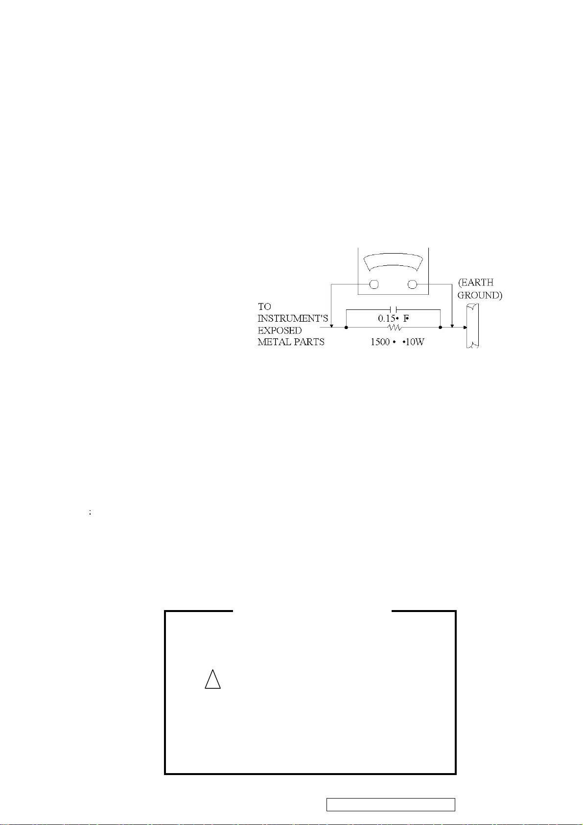
combination 1500 ohm resistor and 0.15uF capacitor.
h
d
5-4 Move the resistor connection to each exposed metallic part and measure the voltage.
5-5 Reverse the polarity of the AC plug in the AC outlet and repeat the above measurement.
5-6 Voltage measured must not exceed 7.5 volt RMS, from any exposed metallic part to ground A leakage current
tester may be used in the above hot check, in which case any current measured must not exceed 5.0 milliamp. In
the case of a measurement exceeding the 5.0 milliamp value, a rework is required to eliminate the chance of shock
hazard.
Note: High voltage is present when this CRT display is operating. Always discharge the anode of the picture tube to the
display chassis to prevent shock hazard.
AC VOLTMETER
Fig. 1
6. IMPLOSION PROTECTION
Picture tubes are equipped with an integral implosion protection system, but care should be taken to avoid damage and
scratching during installation. Use only Panasonic replacement picture tubes.
7. X-RADIATION
WARNING:The only potential source of X-Radiation is the picture tube. However when the high voltage circuit is
operating properly there is no possibility of X-Radiation problem. The basic precaution which must be exercised is to
keep the high voltage at the following factory-recommended level.
Note
7-1 The procedure for adjusting high voltage is shown on page 12.
7-2 If can not be adjust 25.0 KV at immediate service is required to prevent the possibility of premature
component failure.
7-3 To prevent X-Radiation possibility it is essential to use the specified picture tube
It is important to use an accurate periodically calibrated high voltage meter.
IMPORTANT SAFETY NOTICE
There are special components used in this CRT displays which are
important for safety. These parts are identified by the international
symbol
list. It is essential that these critical parts should be replaced wit
manufacture’s specified parts to prevent X-RADIATION, shock, fire,
or other hazards. Do not modify the original design or this will voi
the original parts and labor guarantee.
ViewSonic Corporation Confidential - Do Not Copy G90fB-4
on the schematic diagram and on the replacement parts
2
Page 6
2. Specification
1. CRT : 46CM(19") 90 Deflection, Shadow mask ,29mm Neck, flat high contrast CRT, 0.21mm(H) / 0.25mm
(D) dot pitch, Non-Glare Screen
2. Viewable image Size: 45.7CM (18") diagonal
3. Display Color: Unlimited Colors
4. External Controls:
Power On/Off, OSD key, Function knob: Contrast, Brightness, Degauss, H-Size, H-Center, V-Center, V-Size, ZOOM,
Pincushion, Trapezoid, Pin-Balance, Parallelogram, Rotation, Color Temperature, H-Moire Reduce, V-Morie,
Memory Recall, Language, ViewMeter,OSD position select
5. Input Video Signal
Primary Preset # 1. 1600 X 1200 @ 75HZ
Primary Preset # 2. 1280 X 1024 @ 85HZ
Factory Presets
VESA 800 x 600 @ 75Hz, 85Hz MAC 1024 x 768 @ 75Hz
VESA 1024 x 768 @ 75Hz, 85Hz MAC 1152 x 870 @ 75Hz
VESA 1280 x 1024 @ 75Hz
Other Factory Presets
IND 640 x 400 @ 70Hz VGA 640 x 480 @ 60Hz
VESA 640 x 480 @ 85Hz
6. Display Size
Horizontal Display Size, Primary Preset
Horizontal Display Size, Other Presets 352 mm +/- 4 mm
Vertical Display Size, Primary Preset 264 mm +/- 4 mm
Vertical Display Size, Other Presets
Display Size Adjustment All preset modes shall expand to full screen size.
Auto Sizing +/- 8mm compare to default size and within bezel viewable area.
7. Scanning Frequencies
Horizontal: 30KHz ~ 97KHz
Vertical: 50 Hz ~ 160 Hz
8. Factory Preset Timings: 10
User Timings: 10
9. Misconvergence
A Zone: 0.25 mm Max.
B Zone: 0.35 mm Max.
352 mm +/- 4 mm
264 mm +/- 4 mm
ViewSonic Corporation Confidential - Do Not Copy G90fB-4
3
Page 7
10. Video Bandwidth: 240 MHz
11. Power Source:
Switching Mode Power Supply
AC 90 ~264V, 50/60Hz Universal Type
12. Operating Temperature: 0°C to 40°C Ambient
13. Humidity: 5% to 95% Relative, Non-Condensing
14. Weight: 18.0 kgs / 39.7 (lbs) (Net), 21.2 kgs / 46.7 (lbs) (Gross)
15. Dimensions
Machine Package
Width:
Height:
Depth:
16. External Connection:
15 Pin D-sub Connector
AC Power Cord
17. Power Consumption Modes :
ON Mode < 75Watts
Sleep < 4Watts
Off < 2W (Power switch off)
18. Regulatiory/Safety
North America
Regulatory Filing
WW
445 mm 540 mm
424 mm(378mm w/o Base) 530 mm
465 mm 570 mm
Regulatory filing should be made under the
“VS10794”.
UL60950, cUL60950 or CSA 22.2; DHHS Part 21,
Subpart J X-Ray Protection; FCC, Part 15, Subpart
J, Subpart B;ICES-003, Class B; NOM; Argentina –
TUV/S
International
CB, TCO03 (Black);TUV/GS, TUV/Ergo,
BSMI,CCC,PSB,CE,GOST-R;ISO9241-3 7 8
(covered in TUV-ergo)
ViewSonic Corporation Confidential - Do Not Copy G90fB-4
4
Page 8
Operating instructions
This procedure gives you instructions for installing and using the Color display.
1. Position the display on the desired operation and plug the power cord into a convenient AC outlet. Three-wire
power cord must be shielded and is provided as a safety precaution as it connects the chassis and cabinet to the
electrical conduit ground. If the AC outlet in your location does not have provisions for the grounded type plug,
the installer should attach the proper adapter to ensure a safe ground potential.
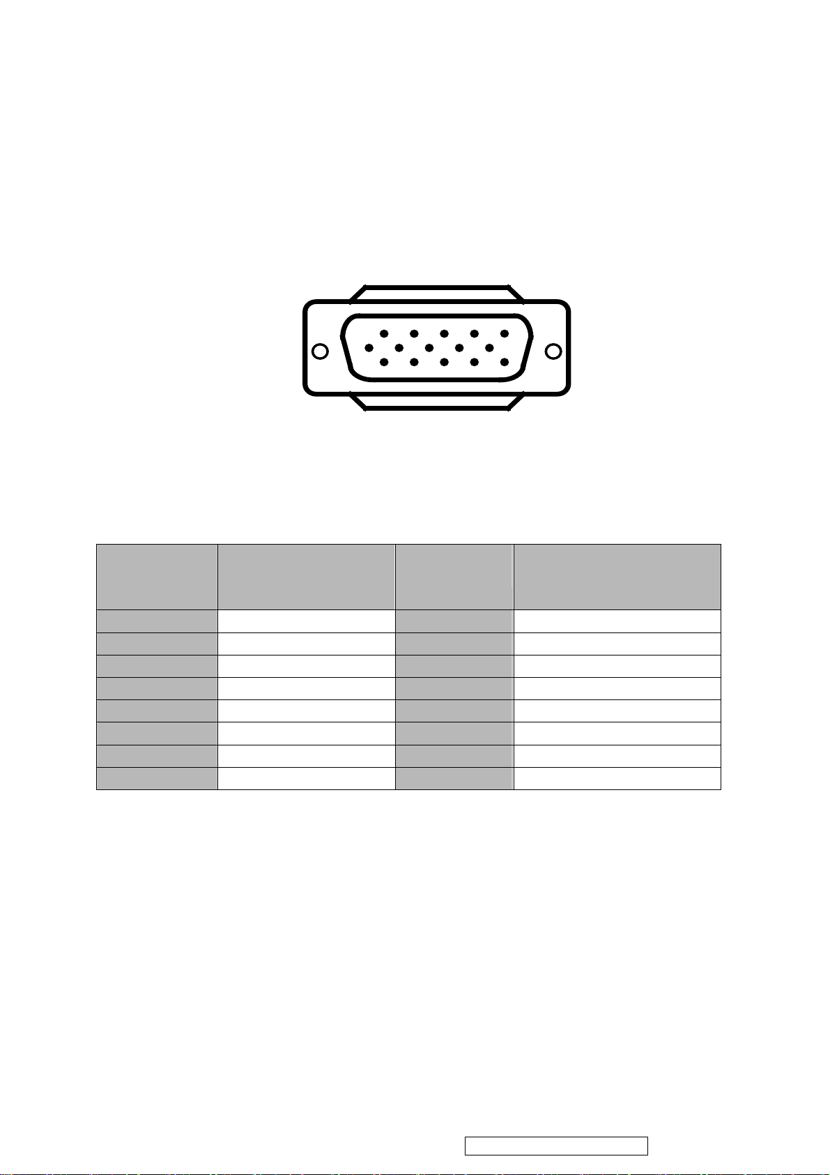
2. Connect the 15-pin color display shielded signal cable to your signal system device and lock both screws on the
connector to ensure firm grounding. The connector information is as follow:
PIN NO.
DESCRIPTION
1. RED-V 9. 5V From PC
2. GREEN-V 10. Sync GND
3. BLUE-V 11. NC
4. NC 12. SDA
5. GND 13. H- SYNC
6. GND-R 14. V- SYNC
7. GND-G 15. SCL
8. GND-B
3. Apply power to the display by turning the power switch to the "ON" position and allow about thirty seconds for
display tube warm-up. The Power-On indicator lights when the display is on.
4. With proper signals feed to the display, a pattern or data should appear on the screen, adjust the brightness and
contrast to the most pleasing display.
5. This monitor has power saving function following the VESA DPMS. Be sure to connect the signal cable to the PC.
6. If your color display requires service, it must be returned with the power cord.
1
6
11 15
5
10
15 - Pin Color Display Signal Cable
PIN NO.
DESCRIPTION
ViewSonic Corporation Confidential - Do Not Copy G90fB-4
5
Page 9
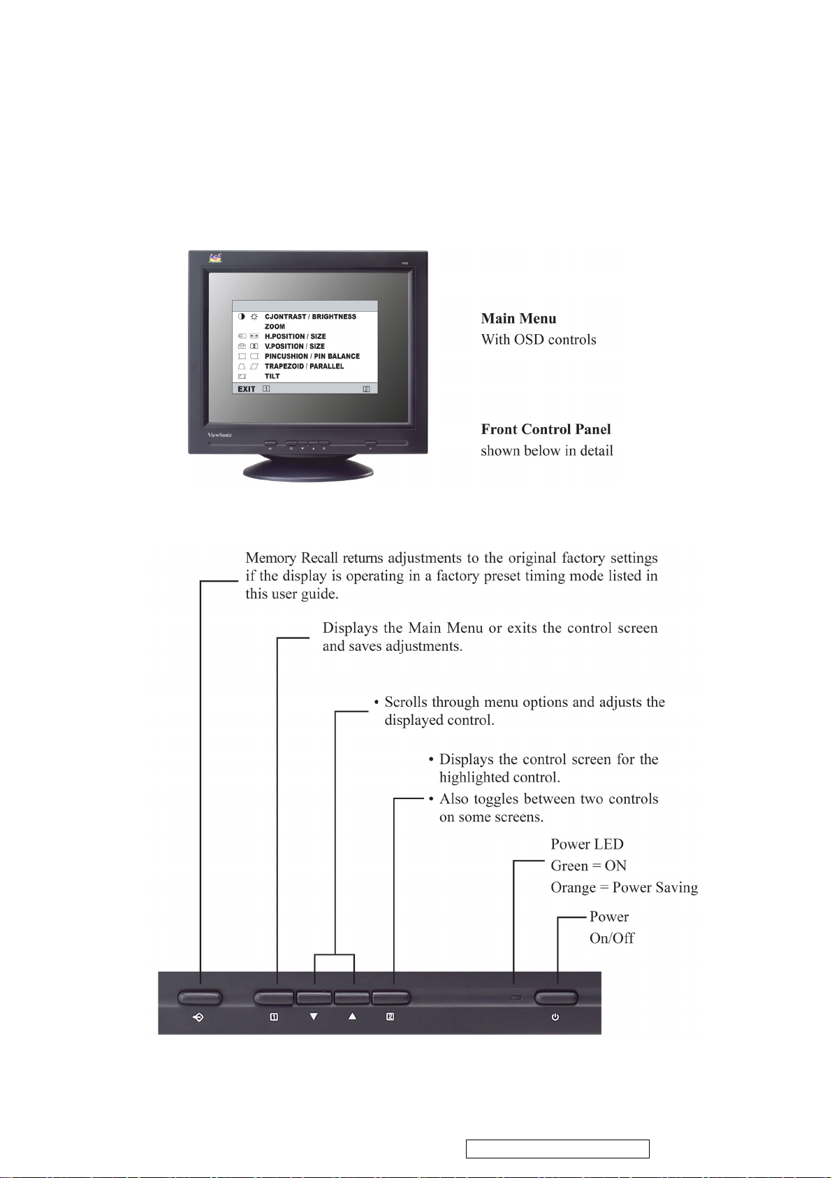
3. Front Panel Function Control Description
Adjusting the Screen Image
Use the buttons on the front control panel to display and adjust the OSD controls .The OSD controls are explained at the top of
the next page and are defined in “Main Menu Controls” on page 8.
ViewSonic Corporation Confidential - Do Not Copy G90fB-4
6
Page 10
OSD Lock Settings
You have the option of using the On Screen Display (OSD) locking feature, OSD LOCK, to prevent unwanted changes
to the current image settings.
• OSD Lock: Press and hold the [1] button on the face of the monitor for 10 seconds. The message "OSD LOCK" will then
display briefly, indicating that the OSD image settings are now locked.
• OSD Unlock: Press and hold the [1] button again for 10 seconds. The message "OSD UNLOCK" will then display
briefly, indicating that the OSD image settings are now unlocked.
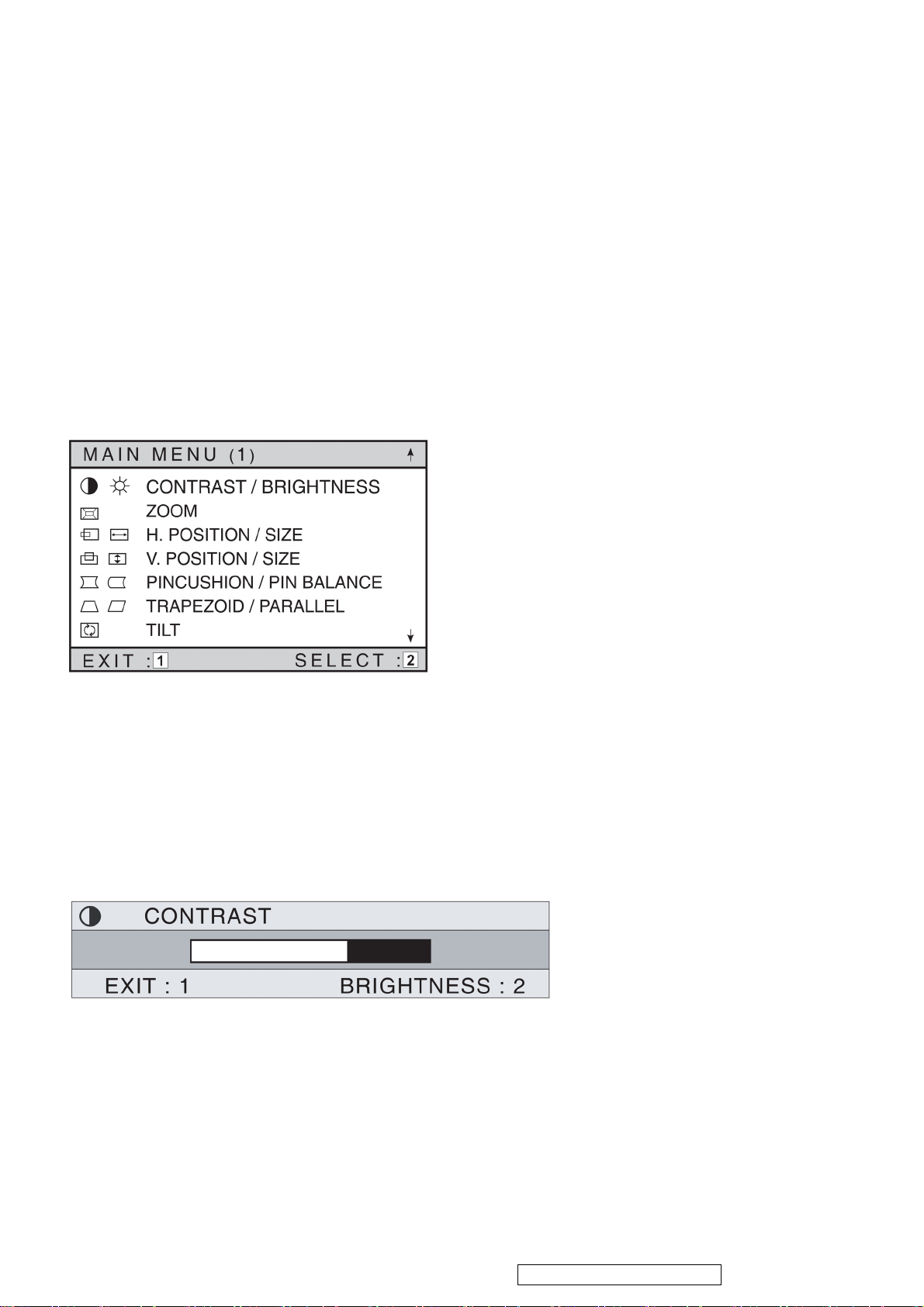
Do the following to adjust the screen image:
1 To display the Main Menu, press button [1].
2 To select a control you want to adjust, press the arrow buttons on the front control panel of your monitor and scroll
through the choices. When the desired control is highlighted, press button [2].
NOTE: Some controls on the Main Menu are listed in pairs, such as Contrast/Brightness. Display control screen (sample
shown in step 3 below). Press button [2] to toggle to the next control in the pair.
3 To adjust the setting, such as CONTRAST in the sample below, press the arrow buttons.
4 To save the control setting and Exit the menu press button [1] twice.
ViewSonic Corporation Confidential - Do Not Copy G90fB-4
7
Page 11
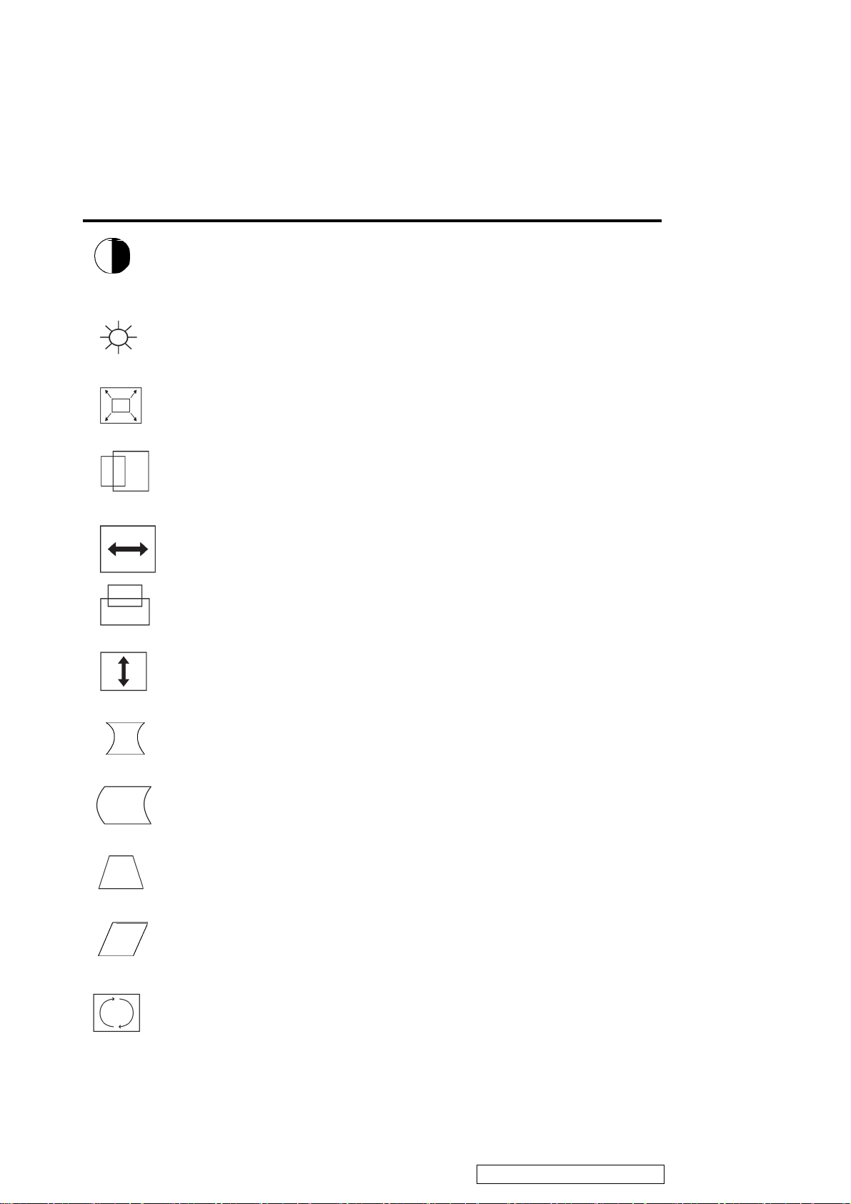
Main Menu Controls
Adjust the menu items shown below by using the up and down buttons.
Control Explanation
Contrast adjusts the difference between the image background (black level)
and the foreground (white level).
Brightness adjusts the background black level of the screen image
ZOOM expands and contracts the entire screen image
Horizontal Position moves the screen image left or right.
Horizontal Size adjusts width of the screen image.
Vertical Position moves the screen image up or down.
Vertical Size adjusts the height of the screen image.
Pincushion curves the vertical sides of the screen image.
Pin Balance curves the vertical edges of the screen image to the left or right.
Trapezoid adjusts the top and bottom of the screen image until they have equal length.
Parallel slants the vertical edges of the screen image until they are parallel.
Tilt rotates the entire screen image.
ViewSonic Corporation Confidential - Do Not Copy G90fB-4
8
Page 12
d
E
Control Explanation
Degauss removes the build-up of magnetic fields that can cause irregular colors to
appear around the edges of screen images. There are two ways to degauss the display:
automatically by turning the monitor on, or manually by selecting the Degauss
control from the menu. With Degauss selected from the menu, press button [2] to
degauss the monitor manually.
Important: Do not degauss repeatedly. Doing so can be harmful
display. Wait at least 20 minutes (before selecting this control again.
ViewMatch® Color provides several color options: several preset color temperatures and User
Color which allows you to adjust red (R), green (G), and blue (B). The factory setting for this
product is 9300K (9300° Kelvin).
9300K — Adds blue to the screen image for cooler white (used in most office settings with
fluorescent lighting).
6500K — Adds red to the screen image for warmer white and richer red.
5000K — Adds blue and green to the screen image for a darker color.
User Color — Individual adjustments for red, green, and blue.
Moire reduces interference patterns that appear as ripples, waves, or unwanted backgroun
color textures. Interference patterns of this type are most noticeable when viewing images
having closely spaced lines or finely detailed patterns.
to the
Language allows you to choose from among several languages for the menus and
control screens: English, French, German, Italian, and Spanish.
Memory Recall returns adjustments to the original factory settings if the display is operating
in a factory preset timing mode listed in this user guide.
xception: This control does not affect changes made with the User Color control.
OSD Position allows you to move the on-screen display menus and control screens.
ViewMeter displays the frequencies (horizontal and vertical) coming from the graphics
card of the computer.
ViewSonic Corporation Confidential - Do Not Copy G90fB-4
9
Page 13

4. Circuit Description
4-1 Micro controller and deflection circuit
MICRO Controller
The micro controller(IC101) core is a 80C51 type. The micro clock frequency of 12 Mhz is derived from the Xtal
2
oscillator,which is running at 48MHz. The DDC interface is suitable to handle DDC2 by a modified hardware I
interface .Standard high current ports,3 ADC pouts with voltage inputs and 4 static standard 8 bit DAC outputs (low
interference) and one PWM output for digital control application are implemented. The central processing unit (CPU)
manipulates operands in two memory spaces.These are the 1024byte internal data memory(consisting of 256 bytes
standard RAM and 768 bytes AUX-RAM) and 48K-byte internal program memory . The programmemory of the
SAA4849 consists of 48K bytes ROM.
The SAA4849P provides sync. Processing with full auto sync. Capability, a flexible SMPS block and an extensive
set of geometry control facilities. Further the IC generates the drive waveforms for DC coupled vertical boosters to the
TDA8172.
H/V sync signals processor
The functions of the sync processor include polarity detection, H-SYNC & V-SYNC signals counting, Programmable
SYNC signals output, free running signal generator. Pin52/Pin53 are for the H-SYNC and V-SYNC input. and the
polarity are setting in the positive. When no signal input, the Pin49 will output a 75Hz V-SYNC free run signal. The
Pin18/20will output a 60KHz H-SYNC free run signal. for the monitor testing use.
C-bus
Reset Circuit (pin23)
There are three ways possible to invoke a reset and initialize the SAA4849 micro controller part:
Via power-on reset circuit
Via watchdog timer overflow(only micro controller reset)
Via deflection reset after start up (only micro controller reset)
The reset pin(pin23) is connected to a Schmitt trigger for nose reduction. A reset is accomplished by holding the Reset pin
HIGH.
C145
22U
5V
x-ray protection
+
R153
2.7K
C102
0.1UF
RST Pin23
ViewSonic Corporation Confidential - Do Not Copy G90fB-4
10
Page 14

The x-ray ptotection (pin22) input XRAY provides a voltage detector with a precise voltage input for X-ray
protection .If the input voltage at XRAY exceeds the upper threshold for 150us to 300us,the system is forced to shut down
by switching off vertical,H-and B-drive signals. There are two different ways to handle the system in case of XRAY
occurrence:
1. If the xray latch enable bit UCXRAY [2] was set to “0” during startup the system will shut down without any interference
of the uC. The deflection controller is set to ldle mode. Restart of the system only possible due to seitching power
off/power on.
2. If register bit UCXRAY [2] was set to “1”, micro controller interaction is allowed .If the micro controller doesn’t interrupt
the system, the system will shut down to ldle mode. For any interaction of the micro controller the XRAY occurrence has
to be acknowledged by the micro controller by clearing the bit SY-STATUS [2]. The micro controller take over the control
of the handling via software. The actual xray pin status can be read through bit SY-STATUS [1].
Quartz Oscillator (pin45, pin46)
The quartz oscillator circuit is available on pins XTAL1 (input) and XTAL2 (output) and works together with an
rd
external 48MHz 3
overtone quartz. As a result the quartz oscillator is always running on 48MHz.Other quartz crystal
frequencies than 48 MHz cannot be used. External capacitors on XTAL1 and XTAL2 are not allowed.
B+ Control Function Block
The B+control block of the SAA4849 has the same behaviour as the TDA4856 with adapted threshol voltages. The
2
circuit allows the user to choose the trigger edge of the HDRV signal and the polarity of the output stage via I
C-Bus.
The B+ control function block of the SAA4849 consists of an Operational Transconductance Amplifier (OTA), a
voltage comparator,a flip-flop and a discharge circuit. This configuration allows easy application for different B+ control
concepts.
HPLL
The horizontal part contains a PLL,which works over the full frequency range from 25kHz to 140 kHz.This range can be
2
reduced by a ower and an upper frequency limit(Write Once Registers HPMAX and HPMIN).Via I
C bus the number of
48MHz clock cycles is sent through the register.The slewing speed during mode change is also programmable in a write once
register (HSLEW)
After the clocks for the HPLL are switched on,the HPLL starts with a fixed freerunning frequency of 60 kHz.The
H-drive pulses are not active and the start up procedure is inhibited.The default setting of register bit HCONTROL [0] will
2
cause the HPLL to slew ,not switch.to the freerunning frequency defined in the I
C register HPFREE( the default value is also
60 kHz).Independent on H-syncs which are possibly present.the HPLL will slew to that freerunning frequency.To achieve an
always defined starting point for the startup procedure,this procedure cannot be interrupted.
ViewSonic Corporation Confidential - Do Not Copy G90fB-4
11
Page 15
4-2 Transistor & diode circuit
Location
BD901 Bridge Rectifier for AC Source
D910 Clamp Diode for snub CKT
D919 Rectifier for Output Voltage
D922 Rectifier for Output Voltage
D923 Rectifier for Output Voltage
D930 Rectifier for Output Voltage
D918 Rectifier for Output Voltage
IC901 Power IC for Switching Power Control.
Q937, Q937 Use for Power Saving
Q912, Q920 Push-Pull Topology to Drive Q911
Q913 Degaussing Switcher Transistor
Circuit function description
IC903 5V Regulator IC
Q403 HOR. Driver Transistor
Q417,Q418,Q416,Q420 Horizontal s correction control MOSFET
Q406 Transistor for H-Size Control
Q705 Brightness Control CKT
Q742 V-Dynamic focus CKT
Q402 Q403 Driver MOSFET
Q901 MOS FET for Switching Power Control.
ViewSonic Corporation Confidential - Do Not Copy G90fB-4
12
Page 16
5. Adjusting Procedure
5-1 Adjustment conditions and precautions
1. Approximately 30 minutes should be allowed for warm up before proceeding.
2. Adjustments should be undertaken only on those necessary elements since most of them have been carefully preset
at the factory.
5-2 Main adjustments
NO. FUNCTION LOCATION DESIGNATION
1. 14V ADJ PCB - MAIN VR903
2. B + ADJ PCB - MAIN VR902
3. SCREEN ADJ FLY BACK TRANS T402 SCREEN VR
4. FOCUS ADJ FLY BACK TRANS T402 FOCUS
VR1&VR2
5. ABL ADJ PCB - MAIN AB in factory OSD
6.
FUNCTION ADJ -MENU
PCB - MAIN (SW101)
-UP ▲ PCB - MAIN (SW102)
-DOWN ▼ PCB - MAIN (SW103)
-SELECT
5-3 Adjustment method
1. 14V, B + & HV voltage adjustment:
A. Chroma-2000 Signal generator or PC equivalent set mode 1, VGA 640X480 pattern 1.0.
B. Connect a DC Volt meter between TP901 and ground, then adjust VR903to be 14VDC.
C. Connect a DC Volt meter between TP902 and ground, then adjust VR902 to be 65.5 VDC.
PCB - MAIN (SW104)
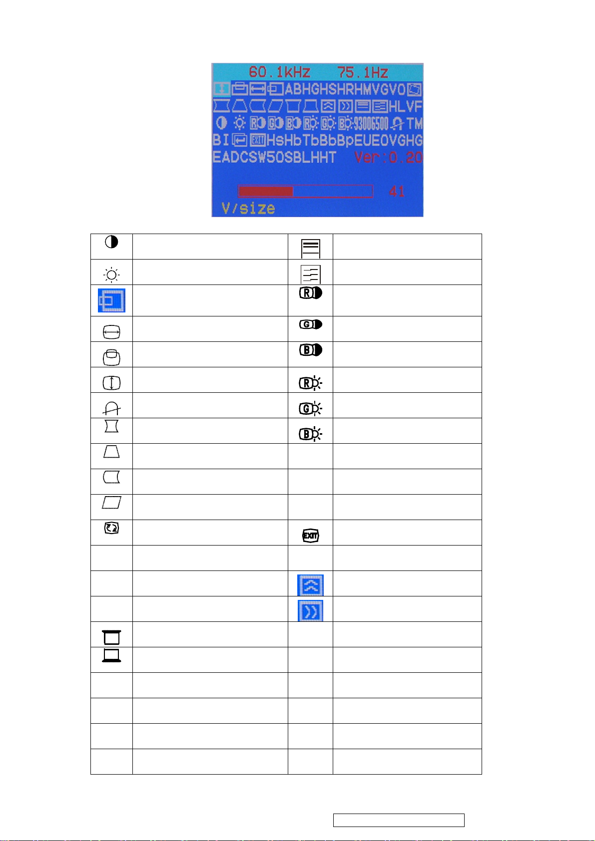
2. Factory preset Timings Adjustment:
A. Press
B. Press the Up Key to select the "ZOOM" function, then press the MENU Key. While do not release the MENU Key
until the OSD window changed to the Factory preset window.
C. The Factory preset window contains the following functional controls. Select one of the control. Then press the
Up/Down Key to adjust its value for the optimum picture.
Key to show OSD window press Up or Down Key to switch the functional controls.
ViewSonic Corporation Confidential - Do Not Copy G90fB-4
13
Page 17
CONTRAST
BRIGHTNESS V-LINEARITY
V-LINEARITY
HT
HG
HS
HR
HM
Hs
Hb
H-CENTER
H-SIZE
V-CENTER
V-SIZE
DEGAUSS
PINCUSHION
TRAPEZOID
PIN-BALANCE
PARALLELOGRAM
ROTATION
HC/RASTER
9300
6500
50
COLOR TEMPERATURE
COLOR TEMPERATURE
COLOR TEMPERATURE
MAX V-SIZE GAIN RANGE
R-GAIN
G-GAIN
B-GAIN
R-BIAS
G-BIAS
R-BIAS
OSD EXIT
VG
H-SIZE GAIN H-MOIRE REDUCE
SUB H-SIZE V-MOIRE REDUCE
TOP CORNER
BOTTOM CORNER
V-HV Variation rate ajust
HL
VF
H-Linearity Modify
V-FOCUS ADJUST
BURN IN TIME
TM
MAX H-SIZE RANGE
SET BURN-IN
BI
SUB H-SIZE
BOTTOM BALANCE
Bb
H-SIZE WAVE BALANCE
B+ VOLTAGE ADJUST
Bp
ViewSonic Corporation Confidential - Do Not Copy G90fB-4
14
Page 18

Tb
EO
VG
HG
SB
TOP BALANCE
EU
EHT OFFSET
EA
MAX V-SIZE GAIN RANGE
DC
H-SIZE GAIN
SW
HIGH BRIGHTNESS SELECT
LH
RETURN
EHT CURRENT
EHT AUTO ADJUST
Video IC dc off set
H-frequency select
Brightness Save
V-CENTER OFFSET
VO
AB
D. To switches the input signal to the other Timing Mode. Please follow step A ~ C to get the optimum picture.
ABL ADJUSTMENT
E. Select the "
to the original OSD window.(user's operating condition)
F. The setting data of the CONTRAST, BRIGHTNESS, PIN-BALANCE, PARALLELOGRAM, ROTATION,
COLOR TEMPERATURE are common mode saved in the memory. Don't needed adjust it individual at every
timing Mode and save in the memory.
3. White Balance, Luminance adjustment:
A. Press MENU Key to show OSD menu ,and press the down Key to select the "size/center" function, then press the
menu Key to enter second menu, press the down key to select “ ”(zoom) about 10S,,then enter into factory setting
area for modulation.
B. Set R,G,B gain DAC value for 50, R ,G ,B bias DAC value for 60.
C. Raster Pattern, Brightness & contrast ratio MAX, fix to G-BIAS,fix to 60. adjust R or B bias, make x=265±10,
y=290±10, adjust G2,make Y=3.5 cd/m
" RETURN function and press the MENU Key, then the Factor Preset window will be returned
2
,and then adjust brightness,make Y=0.05 cd/m
2
,then save it into
9300K,6500K,5000K color temprature.
D. Adjust R or G or B gain, make x=346±10, y=359±10, Y=150±5 cd/m
E. Adjust R or G or B gain, make x=313±10, y=329±10, Y=150±5 cd/m
F. Adjust R or G or B gain, make x=283±10, y=297±10, Y=150±5 cd/m
G. After modulation, it’s necessary to check if the white balance accords with the normal specification. If not, which
needs reset.
4. Focus Adjustment:
A. Under 1024×768 Fv: 85Hz with character full page.
B. Adjust brightness to center and contrast to max.
ViewSonic Corporation Confidential - Do Not Copy G90fB-4
2
,then save it into 5000K color temprature .
2
,then save it into 6500K color temprature .
2
,then save it into 9300K color temprature
15
Page 19

C. Then adjust focus VR1 to a fine vertical line.
D. Adjust focus VR2 to a fine horizontal line.
E. Repeat step C & D.then fix the Focus VR, G2 VR .
5. Purity Adjustment
A. Be sure that the display is not being exposed to any external magnetic fields.
B. Ensure that the spacing between the Purity, Convergence, Magnet, (PCM), assembly and the CRT stem is 29mm.
(See below diagram)
C. Produce a complete, red pattern on the display. Adjust the purity magnet rings on the PCM assembly to obtain a
complete field of the color red. This is done by moving the two tabs in such a manner that they advance in an
opposite direction but at the same time to obtain the same angle between the two tabs, which should be
approximately 180'.
D. Check the complete blue and complete green patterns to observe their respective color purity. Make minor
adjustments if needed.
RELATIVE PLACEMENT OF TYPICAL COMPONENTS
6. Convergence adjustment
A. Produce a magenta crosshatch on the display.
B. Adjust the focus for the best overall focus on the display.
Also adjust the brightness to the desired condition.
C. Vertical red and blue lines are converged by varying the angle between the two tabs of the 4 pole magnets on the
PCM assembly. (See above diagrams)
D. Horizontal red and blue lines are converged by varying the two tabs together, keeping the angle between them
constant.
E. Produce a white crosshatch pattern on the display.
F. Vertical green and magenta lines are converged by varying the angle between the two tabs of the 6-pole magnets.
G. Horizontal green and magenta lines are converged by varying the two tabs together, keeping the angle between
them constant.
Purity Magnets
6-pole Convergence Magnets
4-pole Convergence Magnets
Deflection Yoke
ViewSonic Corporation Confidential - Do Not Copy G90fB-4
16
Page 20

6. Trouble Shooting Flow Chart
N
,
R
Y
V
6-1. No raster,CRT relative circuit problems
CHECK MAIN BOARD POWE
SUPPLY: 12V, 180V, 83V, -12V, 6.3V
NG
OK
PLEASE CHECK HIGH VOLTAGE OF
NG
CRT ABOUT 25.5~26.5KV
NG
OK
NG
CHECK THE HEATER VOLTAGE AT
CRT SOCKET ABOUT 6.3V
OK
NG
CHECK G2 VOLTAGE ABOUT 550~650V CHECK FBT
OK
CHECK THE G1 VOLTAGE ABOUT –16
NG
AT BRIGHTNESS MAX
OK
OK
CHECK THE CATHODE VOLTAGE
ABOUT 60V
6-2. Abnormal DDC (Plug & Play)
CHECK IC101 PIN 16 VOLTAGE ABOUT 5V
PLEASE CHECK POWER SAVING
CIRCUIT OR POWER SUPPL
CIRCUIT.
ENTER POWER OR POWER CIRCUIT
FAIL .
CHECK THE CIRCUIT OF PIN 18/20 OF
IC101
CHECK THE 6.3V SUPPLY CIRCUIT:
Q906,ZD902
CHECK THE G1 CONTROL CIRCUIT:
Q705 RELATIVE CIRCUIT
CRT FAIL
G
OK
CHECK SIGNAL CABLE
OR H802 PIN 2
4 DATA OUTPUT
ViewSonic Corporation Confidential - Do Not Copy G90fB-4
CHECK IC902 GOOD OR FAIL
17
Page 21

6-3. Abnormal video level on screen
N
K
R
NG
CHECK THE VOLTAGE AT
PIN10/14/17/22 OF IC801 ABOUT 5V
OK
NG
CHECK THE SIGNAL OUT ABOUT 0.7VP-P
OK
NG
CHECK THE CLAMP PULSE OF IC801 PIN27
OK
NG
CHECK THE VOLTAGE OF IC801
PIN23/24/25 ABOUT 4VP-P
OK
CHECK THE RELATIVE CIRCUIT OF IC802
6-4. No blanking
CHECK THE RELATIVE
CIRCUIT OF BLANKING
CHECK 5V SUPPLY CIRCUIT
CHECK SIGNAL CABLE O
INTERFACE CARD
CHECK THE RELATIVE CIRCUIT
OF IC801 PIN27
CHECK THE RELATIVE CIRCUIT
OF IC801 PIN23/25/24 OR THE
IC801 FAIL
G
O
CHECK R821 ON VIDEO PCB,
CHECK G1 RELATIVE CIRCUIT
FBT PIN 5 ON MAIN PCB
CHECK THE RELATIVE CIRCUIT
OF FBT
ViewSonic Corporation Confidential - Do Not Copy G90fB-4
18
Page 22

Y
6-5. No signal on screen
NG
CHECK THE VOLTAGE AT
PIN10/14/17/22 OF IC801 ABOUT 5V
OK
CHECK THE VOLTAGE OF IC801
NG
PIN23/24/25 ABOUT 4VP-P
OK
NG
CHECK THE VOLTAGE OF IC802 PIN12
ABOUT 83V AND IC802 PIN2 ABOUT 12V
OK
CHECK THE VOLTAGE OF CRT CATHODE
NG
ABOUT 50VP-P
OK
NG
CHECK THE VOLTAGE GO G2 ABOUT
550V~650V
6-6. Abnormal horizontal width of video
CHECK 5V SUPPLY CIRCUIT
CHECK THE RELATIVE CIRCUIT
OF IC801 PIN23/25/24 OR THE
IC801 FAIL
CHECK THE 83V&12V SUPPL
CIRCUIT OR MAIN BOARD
CHECK THE RELATIVE CIRCUIT
OF IC802 OUT PUT
CHECK FBT RELATIVE CIRCUIT
NG
READJUST H-SIZE FUNCTION CHECK RELATION CIRCUIT OF Q406
OK
CHECK B+ VOLTAGE ABOUT 125.5V AT
NG
H-FREQUENCY=68KHZ
CHECK B+ SUPPLY CIRCUIT
OK
CHECK THE HIGH VOLTAGE ABOUT
25.5~26.5V
NG
REFERENCE TO ITEM7
ViewSonic Corporation Confidential - Do Not Copy G90fB-4
19
Page 23

6-7. Abnormal horizontal linearity
N
K N
N
CHECK L401, Q426, Q420, Q427
AND IC101 PIN9,10,11
Abnormal vertical size
6-8.
READJUST V-SIZE FUNCTION VALUE
CHECK THE IC601 PIN1 ABOUT 11.8V
PIN 4 ABOUT -12V
G
O
CHECK VERT. OSC CIRCUIT
G
OK
READJUST V-SIZE FUNCTION VALUE
6-9. Vertical center
READJUST V-CENTER
G
CHECK D601, C605
RELATIVE CIRCUIT
CHECK THE VOLTAGE OF IC101
RELATIVE CIRCUIT
CHECK IC101 PIN33,34
RELATIVE CIRCUIT
NG
CHECK IC101 AND IC601 RELATIVE
CHECK IC401 AND IC601
RELATIVE CKT
CIRCUIT
6-10. Side-pin cushion distortion
READJUST FOCUS CONTROL
NG
CHECK FOCUS CONTROL UNIT,
FOCUS LEAD WIRE, CRT SOCKET & CRT
6-11. Poor focus
READJUST FOCUS CONTROL
NG
CHECK FOCUS CONTROL UNIT,
FOCUS LEAD WIRE, CRT SOCKET & CRT
ViewSonic Corporation Confidential - Do Not Copy G90fB-4
20
Page 24

NG
K
NG
K
K
NG
NG
K
K
K
N
K
N
N
Q
K
V
6-12. Power supply trouble shooting chart
Before check SW.REG.Please refer to the power supply block diagram power supply output
(A) Variable output: 60V
(B) Constant output : 6.3V, 12V,83V,180.V,-12V
BEAD SET
ABNORMAL VARIABLE OUTPUT
:
CHECK AC LINE
VOLT 120V OR 220V
O
CHECK LINE RECTIFIED
& SMOOTHED VOLT
O
CHECK START C.K.T
R936
O
CHECK T901 O/P
CHECK F901, SW901
CHECK BRIDGE
RECTIFIED
MAKE SURE THAT
THE VARIABLE
OUTPUT IS NOT SHORTED
O
YES
CHECK THE 56V OUTPUT
G
O
CHECK Q911
G
O
CHECK IC101
PIN39,40,41, B+
DRIVER
CHECK D925
911 FAILURE
O
CHECK IC901
O
CHECK SENSE RESISTENCE
CHECK 56V, 12
6.5V CIRCUIT OUTPUT
IC901 FAILURE
IC101 PIN30(ABOUT5V)
O
ViewSonic Corporation Confidential - Do Not Copy G90fB-4
21
Page 25

(
S
R
E
L
T
E
E
A
N
T
N
A
N
N
7. Recommended Spare Parts List
RECOMMENDED SPARE PARTS LIST (G90fB-4M)
ViewSonic Model Number: VS10794-3M
Rev: 1a
Serial No. Prefix: PY9
Item ECR/ECN ViewSonic P/N Ref. P/N Location Universal number# Q'ty
1
Accessories:
2 CRT BOARD B-00004889 CRP995D1NHVWP 1
Board Assembly:
3 CHASSIS FOR P995D-1HSVW B-00004890 CMP995D1NHVWP 1
4 BACK COVE
Cabinets:
5 BAS
6 FRONT PANE
7
Cables:
8
Documentation:
9 U4KB80R E-00004072 93C 50460 16 BD901 1
Electronic
10 220UF 400V E-00004073 67C 3022114P C907 1
Components :
11 FMQ-G2FS E-D-0403-2033 93C 220 13 D408 1
12 RGP10D E-00004895 93C102050152T D911 1
13 FUSE CLIP E-00004658 84C 33 10 F901 1
14 SAA4849PS E-00004059 56C1125575 X IC101 1
15 M24C08-WBN6P E-00002717 56C1133508 IC102 1
16 E-STV8172A E-00004896 56C 533 1 IC601 1
17 LM1246DKA/NA/NOPB E-IC-0401-4019 56C 366509 IC801 1
18 LM2465TA E-00001622 56C 551521 IC802 1
19 TEA1507P E-00004060 56C 625500 S IC901 1
20 COIL E-00004074 73C 147542 H L401 1
21 NTCR 10OHM+-20% 5A THIN E-R-0405-0377 61C 58 9T
22 PTCR 9OHM+-20% 220V WAL E-00002725 61C 52 27 4W PR901 1
23 2SC5905 E-00004089 57C 706508 Q403 1
24 BC547B E-00004897 57C 4197AP T Q407 1
25 STP9NK70Z E-00004071 57C 724502 Q901 1
26 SPARK GAP E-00004898 62A 10 16 W SG408 1
27 CRT SOCKET(QQ FOCUS) E-00002860 87C3504 ZW SOCKE
28 MINI PUSH SWITCH M-SW-0815-0208 77C411A 2 S SW901 1
29 CARTO
Packing Material:
30 EPS CUSHIO
31 EPS CUSHIO
Description
POWER CORD
SIGNAL CABL
QUICK SET UP GUID
-4M) A-00004049 89C402A18N I
C-00004891 34C6286 E7 T 1
C-00004892 34C 741 QE B 1
C-00004893 34C6285AFD
CB-00004894 89C 71B8MC HM 1
DC-00004672 41C 6870913
R901 1
P-00004899 44C6925709 4
P-00004077 44C6932 1 1
P-00004078 44C6932 2 1
1
1
1
1
1
Remark 1:
Remark 2:
Above listed items are examples, supplier can expand the rows to add more necessary items.
All revised RSPLs with newly added items or any change made should be highlighted and correlated with the ECN/ECR approved by
ViewSonic Corporation. This is to eliminate repeated cross checks of each item between this version and prior versions.
ViewSonic Corporation Confidential - Do Not Copy G90fB-4
22
Page 26

(
S
R
E
L
T
E
E
A
N
T
N
A
N
N
RECOMMENDED SPARE PARTS LIST (G90fB-4E)
ViewSonic Model Number: VS10794-3E
Rev: 1a
Serial No. Prefix: PYA
Item ECR/ECN ViewSonic P/N Ref. P/N Location Universal number# Q'ty
1
Accessories:
2 CRT BOARD B-00004889 CRP995D1NHVWP 1
Board Assembly:
3 CHASSIS FOR P995D-1HSVW B-00004890 CMP995D1NHVWP 1
4 BACK COVE
Cabinets:
5 BAS
6 FRONT PANE
7
Cables:
8
Documentation:
9 U4KB80R E-00004072 93C 50460 16 BD901 1
Electronic
10 220UF 400V E-00004073 67C 3022114P C907 1
Components :
11 FMQ-G2FS E-D-0403-2033 93C 220 13 D408 1
12 RGP10D E-00004895 93C102050152T D911 1
13 FUSE CLIP E-00004658 84C 33 10 F901 1
14 SAA4849PS E-00004059 56C1125575 X IC101 1
15 M24C08-WBN6P E-00002717 56C1133508 IC102 1
16 E-STV8172A E-00004896 56C 533 1 IC601 1
17 LM1246DKA/NA/NOPB E-IC-0401-4019 56C 366509 IC801 1
18 LM2465TA E-00001622 56C 551521 IC802 1
19 TEA1507P E-00004060 56C 625500 S IC901 1
20 COIL E-00004074 73C 147542 H L401 1
21 NTCR 10OHM+-20% 5A THIN E-R-0405-0377 61C 58 9T
22 PTCR 9OHM+-20% 220V WAL E-00002725 61C 52 27 4W PR901 1
23 2SC5905 E-00004089 57C 706508 Q403 1
24 BC547B E-00004897 57C 4197AP T Q407 1
25 STP9NK70Z E-00004071 57C 724502 Q901 1
26 SPARK GAP E-00004898 62A 10 16 W SG408 1
27 CRT SOCKET(QQ FOCUS) E-00002860 87C3504 ZW SOCKE
28 MINI PUSH SWITCH M-SW-0815-0208 77C411A 2 S SW901 1
29 CARTO
Packing Material:
30 EPS CUSHIO
31 EPS CUSHIO
Description
POWER CORD
SIGNAL CABL
QUICK SET UP GUID
-4E)
A-00004662 89C404A18N L
C-00004891 34C6286 E7 T 1
C-00004892 34C 741 QE B 1
C-00004893 34C6285AFD
CB-00004894 89C 71B8MC HM 1
DC-00004672 41C 6870913
R901 1
P-00004899 44C6925709 4
P-00004077 44C6932 1 1
P-00004078 44C6932 2 1
1
1
1
1
1
Remark 1:
Above listed items are examples, supplier can expand the rows to add more necessary items.
Remark 2: All revised RSPLs with newly added items or any change made should be highlighted and correlated with the ECN/ECR approved by
ViewSonic Corporation. This is to eliminate repeated cross checks of each item between this version and prior versions.
ViewSonic Corporation Confidential - Do Not Copy G90fB-4
23
Page 27

(
0
S
R
E
L
T
E
E
A
N
T
N
A
N
N
RECOMMENDED SPARE PARTS LIST (G90fB-4P)
ViewSonic Model Number: VS10794-3P
Rev: 1a
Serial No. Prefix: PYC
Item ECR/ECN ViewSonic P/N Ref. P/N Location Universal number# Q'ty
Accessories:
Board Assembly:
Cabinets:
Cables:
Documentation:
Electronic
Components :
Packing Material:
Description
POWER CORD
CRT BOARD B-00004889 CRP995D1NHVWP 1
CHASSIS FOR P995D-1HSVW B-00004890 CMP995D1NHVWP 1
BACK COVE
BAS
FRONT PANE
SIGNAL CABL
QUICK SET UP GUID
U4KB80R E-00004072 93C 50460 16 BD901 1
220UF 400V E-00004073 67C 3022114P C907 1
FMQ-G2FS E-D-0403-2033 93C 220 13 D408 1
RGP10D E-00004895 93C102050152T D911 1
FUSE CLIP E-00004658 84C 33 10 F901 1
SAA4849PS E-00004059 56C1125575 X IC101 1
M24C08-WBN6P E-00002717 56C1133508 IC102 1
E-STV8172A E-00004896 56C 533 1 IC601 1
LM1246DKA/NA/NOPB E-IC-0401-4019 56C 366509 IC801 1
LM2465TA E-00001622 56C 551521 IC802 1
TEA1507P E-00004060 56C 625500 S IC901 1
COIL E-00004074 73C 147542 H L401 1
NTCR 10OHM+-20% 5A THIN E-R-0405-0377 61C 58 9T
PTCR 9OHM+-20% 220V WAL E-00002725 61C 52 27 4W PR901 1
2SC5905 E-00004089 57C 706508 Q403 1
BC547B E-00004897 57C 4197AP T Q407 1
STP9NK70Z E-00004071 57C 724502 Q901 1
SPARK GAP E-00004898 62A 10 16 W SG408 1
CRT SOCKET(QQ FOCUS) E-00002860 87C3504 ZW SOCKE
MINI PUSH SWITCH M-SW-0815-0208 77C411A 2 S SW901 1
CARTO
EPS CUSHIO
EPS CUSHIO
-4P)
A-0000268
C-00004891 34C6286 E7 T 1
C-00004892 34C 741 QE B 1
C-00004893 34C6285AFD
CB-00004894 89C 71B8MC HM 1
DC-00004672 41C 6870913
P-00004899 44C6925709 4
P-00004077 44C6932 1 1
P-00004078 44C6932 2 1
89C420A18N I
R901 1
1
1
1
1
1
Remark 1:
Remark 2:
Above listed items are examples, supplier can expand the rows to add more necessary items.
All revised RSPLs with newly added items or any change made should be highlighted and correlated with the ECN/ECR approved by
ViewSonic Corporation. This is to eliminate repeated cross checks of each item between this version and prior versions.
ViewSonic Corporation Confidential - Do Not Copy G90fB-4
24
Page 28

L
L
E
E
N
L
E
W
(
)
W
N
N
G
G
L
BOM LIST (G90fB-4M/E/P)
ViewSonic Model Number: VS10794-3M/E/P
Rev: 1a
Serial No. Prefix: PY9 / PYA / PYC
Item ViewSonic P/N Ref. P/N Description Location Universal number# Q'ty
1 B-00004890 CMP995D1NHVWP
2 #N/A 1C 503 5T 47
3 #N/A 5C600604075S
4 #N/A 5C600605075S
5 #N/A 7C 1 4V27
6 #N/A 11C 112500
7 #N/A 11C 115500
8 PL-00002752 12C 385 1
9 #N/A 23C3182 1
10 #N/A 33C6336 E7 T
11 #N/A 33C6337 1
12 #N/A 33C6338 E7 T
13 #N/A 33C6339 E7 T
14 #N/A 33C6918 Y A
15 #N/A 34C 741 QE B
16 C-00004893 34C6285AFD T
17 C-00004891 34C6286 E7 T
18 #N/A 34C6293 QE B
19 #N/A 40C 152509
20 #N/A 40C 152512
21 #N/A 40C 153 19 3B
22 #N/A 40C 58162410A
23 #N/A 40C 58162435A
24 #N/A 40C 581625 2A
25 #N/A 40C 581709 1A
26 #N/A 40C 58170918D
27 #N/A 40C 58170923A
28 #N/A 40C 90P709 3A
29 DC-00004672 41C 6870913A
30 #N/A 41C 6870914A
31 P-00004899 44C6925709 4A
32 P-00004077 44C6932 1
33 P-00004078 44C6932 2
34 P-00004101 45C 76 20 RN
35 P-00002871 45C 76 28 V3
36 #N/A 45C 76 34 RN
37 #N/A 45C 88601 C
38 #N/A 50C 500500
39 #N/A 50C 500502
40 #N/A 50C 502 2
41 #N/A 50C 502 5
42 #N/A 51C 6 4
43 #N/A 52C 1150 C
44 #N/A 52C 1185
45 #N/A 52C 1185 1
46 #N/A 52C 1186
47 #N/A 70CD918709 3B
48 #N/A 85C6024506
49 CB-00004894 89C 71B8MC HM
50 A-00004049 89C402A18N IS
51 A-00004529 89C402A18N LS
52 #N/A 95C 91205810
53 HW-00002750 B1C1035 10 47
54 HW-00002758 D1C1140 7128
55 HW-00002749 Q1C 340 16 47
56 E-00004542 750A1697 77BAG
57 E-00003861 750C55382AV
58 #N/A AMP995D1NHVWP
59 #N/A
60 B-00004889 CRP995D1NHVWP
61 #N/A 9C 203 8
62 #N/A 9C 203 8
63 #N/A 11C6033 3
64 #N/A 15C5640 1 A
65 #N/A 19C 553 3
66 #N/A 19C 553500
67 #N/A 33C3074 1
68 #N/A 33C3192 4
69 #N/A 33C3803 3
70 #N/A 40C 581624 2B
71 E-IC-0401-2813 56C 133 5 ST
MP995D1NSMTV
ViewSonic Corporation Confidential - Do Not Copy G90fB-4
CHASSIS FOR P995D-1HSVW
SCREW FOR CRT
CRT WASHER
CRT WASHER
WOODEN PALLET
WIRE MOUNT
FBT CLIP
RUBBER FOOT
Logo
POWER KNOB
LENS
KEY PAD
OSD KNOB
S.W.CAP
BASE
FRONT PANEL
BACK COVER
SWIVEL
RECYCLE LABE
RECYCLE LABE
CRT WARNING LABEL
H/V LABEL
MANUAL P/N LABEL
PALLET LABEL
CARTON LABEL
PALLET LABEL
VIEWCARE LABEL
RATING LABEL
QUICK SET UP GUIDE
TCO'03 PAPER
CARTON
EPS CUSHION
EPS CUSHION
PE BAG FOR MONITOR
PE BAG FOR MANUAL
PE BAG FOR BASE
EPE COVER
CABLE TIE
CABLE TI
PLASTIC TI
CABLE TIE
SILICO
TAPE
MIDDLE TAPE FOR CARTON
BIG TAPE
SMALL TAPE
CD MANUA
HIELD
SINGEL CABL
POWER CORD
POWER CORD
WIRE HARNESS
SCRE
SCREW 4X7
SCREW
DEGAUSSING COIL
SDI 19" DFT-M WB CRT
MAIN BOARD FOR P995D-1H
MAIN BOARD SMT FOR P995
CRT BOARD
BRASS PIN
BRASS PIN
PCB SUPPORT
B GND LUG
SPRING PIECE
SPRING PIECE
2P PLU
4P PLU
WAFER EH-E
CHASSIS LABE
L7805CV
FOR AC
25
V000 0
V000 0
V000 0
V000 0
E089B 1
E089A 1
E089A 0
E750A 0
GND1 1
GND2 1
GND-PI
GND-PI
CN902 1
P402 1
P403 1
IC905 1
1
4
2
2
0
1
1
1
1
1
1
1
1
1
1
1
1
1
1
1
0
1
0
1
1
1
1
1
1
1
1
1
1
2
7
2
1
9
2
6
6
5
1
1
1
1
1
4
1
1
1
1
2
2
1
1
1
Page 29

Item ViewSonic P/N Ref. P/N Description Location Universal number# Q'ty
F
2
72 #N/A 56C 139 5
73 #N/A 56C 379 16
74 E-00004060 56C 625500 S
75 E-00004059 56C1125575 X
76 E-00002717 56C1133508
77 E-00002859 61C 52 27 4J
78 E-00002725 61C 52 27 4W
79 #N/A 61C 208151 64
80 #N/A 61C 208390 64
81 #N/A 61C152M150 64
82 #N/A 61C152M330 64
83 #N/A 61C152M473 64
84 #N/A 61C152M560 64
85 #N/A 61C152M823 64
86 #N/A 61C153M189 59
87 #N/A 61C153M202 59 R426 1
88 #N/A 61C153M222 59
89 E-SP-0417-0097 62A 10 16 J
90 E-00004898 62A 10 16 W
91 #N/A 63C210J1042CU
92 #N/A 63C210J1051CC
93 #N/A 63C210J1051CR
94 #N/A 63C210J1052CC
95 #N/A 63C210J1052CU
96 #N/A 63C210J1842CU
97 #N/A 63C210J1843CC
98 #N/A 63C210J3324BF
99 #N/A 63C210J3324BU
100 #N/A 63C210J3342CC
101 #N/A 63C210J3942CC
102 #N/A 63C210J4028FC
103 #N/A 63C210J4732AC
104 #N/A 63C210J4732AU
105 #N/A 63C210J4734CC
106 #N/A 63C210J4734CR
107 E-00003272 64C178J824 1T
108 #N/A 65C 2K103 3A6921
109 E-00004473 65C 2K121 5A6921
110 E-00004473 65C 2K121 5A6921
111 #N/A 65C305M2222B2
112 #N/A 65C305M2222B2
113 #N/A 65C305M2222B2
114 #N/A 65C305M2222BH
115 #N/A 65C305M2222BH
116 #N/A 65C305M2222BH
117 E-00002739 67C 3022114K
118 E-00004073 67C 3022114P
119 #N/A 67C 70109 10
120 #N/A 67C 215101 9
121 E-00002738 67C 305101 9
122 E-00002738 67C 305101 9
123 #N/A 67C 305102 3
124 #N/A 67C 305102 4
125 #N/A 67C 305470 3
126 #N/A 67C 305470 10
127 #N/A 67C 305471 4
128 #N/A 67C 305471 3T
129 #N/A 67C 305471 3T
130 #N/A 67C 305472 3
131 #N/A 67C 309330 12
132 #N/A 67C 309471 4
133 #N/A 71C 55 24
134 #N/A 71C 55 29
135 #N/A 71C 55 29
136 #N/A 71C 100 8
137 #N/A 71C 100 9
138 #N/A 71C 100501 S
139 E-00004094 73A 174 7S3G
140 E-00004074 73C 147542 H
141 #N/A 73C 253111 T
142 #N/A 73C 253512 T
143 #N/A 73C 25810110H
144 #N/A 73C 25810110H
145 #N/A 73C 25810110T
146 #N/A 73C 25810110T
147 #N/A 73C 25818110H
TCET 1103
UC3843ACD
TEA1507P
SAA4849PS
M24C08-WBN6P
PTCR
PTCR 9OHM+-20% 220V WAL
MOFR 150 OHM +-5% 1W
MOFR 39 OHM +-5% 1W
MOFR 15 OHM+-5% 2W
MOFR 33 OHM+-5% 2W
MOFR 47K OHM+-5% 2W
MOFR 56 OHM+-5% 2W
MOFR 82K+-5% 2W
MOFR 1.8 OHM +-5% 3W
MOFR 2.2K OHM +-5% 3W
SPARK GAP 1KV +500-100V
SPARK GAP
0.1UF 250V
1UF 100V
1UF 100V
1.0UF 250V
MPP +-5% 1UF/250V
0.18UF +-5% 250V FOR CA
0.18UF +-5% 400V FOR CA
3.3NF 630V
3.3NF 630V
.33UF +-5% 250V FOR CAM
.39UF +-5% 250V
4000PF/2KV
MPP, 0.047UF 250V,J
MPP, 0.047UF 250V,J
MPP 0.047UF +-5% 630V
0.047UF +-5% 630V
0.82UF 100V
0.01UF 2KV
120PF 2KV
120PF 2KV
2.2NF,400VAC,Y2,M
2.2NF,400VAC,Y2,M
2.2NF,400VAC,Y2,M
2.2NF,400VAC,Y2,M
2.2NF,400VAC,Y2,M
2.2NF,400VAC,Y2,M
220UF +-20% 400V ELITE
220UF 400V
1UF 160V
100UF +-20% 100V
100UF +-20% 100V
100UF +-20% 100V
1000 UF +-20% 16V
1000UF +-20% 25V
47UF +-20% 16V
47UF +-20% 160V
470UF +-20% 25V
470UF +-20% 16V
470UF +-20% 16V
4700UF 16V
33UF +-20% 250V
470UF +-20% 25V
A FERRITE BEAD 10*6.0*0.6
FERRITE BEAD
FERRITE BEAD
FERRITE CORE 12*25*15
FERRIRE CORE 28.5*17.5*
CORD
LINE FILTER
COIL
CHOKE COIL
20MH
100UH
100UH
100UH
100UH
180UH
IC902 1
IC405 1
IC901 1
IC101 1
IC102 1
PR901 0
PR901 1
R468 1
R400 1
R455 1
R451 1
R927 1
R917 1
R427 1
R428 1
R429 1
SG408 0
SG408 1
C428 1
C436 1
C436 0
C427 0
C427 1
C423 1
C426 1
C461 0
C461 1
C415 1
C420 1
C438 1
C712 0
C712 1
C721 1
C721 0
C439 1
C919 1
C488 1
C489 1
C961 0
C962 0
C963 0
C961 1
C962 1
C963 1
C907 0
C907 1
C401 1
C936 1
C742 1
C936 0
C939 1
C944 1
C910 1
C930 1
C945 1
C603 1
C605 1
C482 1
C432 1
C935 1
FB903 1
FB412 1
J022 1
FBT
FBTG
L901 1
L401 1
L406 1
L402 1
L903 0
L904 1
L903 1
L904 0
L902 0
ViewSonic Corporation Confidential - Do Not Copy G90fB-4
26
1
1
1
Page 30

Item ViewSonic P/N Ref. P/N Description Location Universal number# Q'ty
148 #N/A 73C 25818110H
149 #N/A 73C 25818110H
150 #N/A 73C 25818110T
151 #N/A 73C 25818110T
152 #N/A 73C 25818110T
153 #N/A 75A 334203
154 #N/A 77C 260 5 4
155 E-RL-0414-0110 77C 260 5 2W
156 #N/A 77C 602 1 CJ
157 #N/A 77C 602 1 CJ
158 #N/A 77C 602 1 CJ
159 #N/A 77C 602 1 CJ
160 #N/A 77C 602 1 CJ
161 M-SW-0815-0208 77C411A 2 S
162 M-SW-0815-0200 77C411A 2 CJ
163 #N/A 79C 167114 HC
164 #N/A 79C 167502 T
165 #N/A 79C 995 1 B
166 E-00004539 80C995D 1 L2
167 #N/A 81C 11 7 GP
168 E-00004658 84C 33 10
169 #N/A 84C 41 4
170 E-00004072 93C 50460 16
171 #N/A 93C 6073F
172 E-00004342 93C30408AT
173 #N/A 93C3060 4
174 #N/A 95C8013 10609
175 #N/A 95C8013 11619
176 #N/A B1C1040 12128
177 #N/A B1C1140 6128
178 HW-00002758 D1C1140 7128
179 HW-00004380 M1C1140 6128
180 #N/A M1C1730 8128
181 #N/A 705C995DC5704P
182 #N/A 750A55379951AI
183 #N/A 750A55379951AK
184 #N/A 705C995DAC101P
185 #N/A 705C995DC5601P
186 #N/A 705C995DC5602P
187 #N/A 705C995DC5702P
188 #N/A 705C995DC5703P
189 #N/A 705C995DC6101P
190 PL-00002759 6C 31 4
191 PL-00002759 6C 31 4
192 PL-00002759 6C 31 4
193 PL-00002759 6C 31 4
194 PL-00002759 6C 31 4
195 PL-00002759 6C 31 4
196 PL-00002759 6C 31 4
197 PL-00002759 6C 31 4
198 PL-00002759 6C 31 4
199 PL-00002759 6C 31 4
200 PL-00002759 6C 31 4
201 PL-00002759 6C 31 4
202 PL-00002759 6C 31 4
203 PL-00002759 6C 31 4
204 PL-00002759 6C 31 4
205 #N/A 6C 31500
206 #N/A 6C 31500
207 #N/A 6C 31500
208 #N/A 6C 31501
209 #N/A 6C 31501
210 #N/A 6C 31502
211 #N/A 6C 31502
212 E-00003625 95C 90 23
213 #N/A 715C1480 1VSC
214 E-00003625 95C 90 23
215 E-00003625 95C 90 23
216 E-00003625 95C 90 23
217 E-00003625 95C 90 23
218 E-00003625 95C 90 23
219 E-00003625 95C 90 23
220 E-00003625 95C 90 23
221 E-00003625 95C 90 23
222 E-00003625 95C 90 23
223 E-00003625 95C 90 23
180UH
180UH
180UH
180UH
180UH
CFVR 20K OHM +-20%
RELAY
RELAY OSA-SS-212DM5
TACT SWITCH TSVB-2-T-NP
TACT SWITCH TSVB-2-T-NP
TACT SWITCH TSVB-2-T-NP
TACT SWITCH TSVB-2-T-NP
TACT SWITCH TSVB-2-T-NP
MINI PUSH SWITCH
MINI PUSH SWITCH
DRIVE X'FMR
DEIVER TRANSFORMER
FBT SAMPO
TRANS LITAI
GP32052CE/DIY-ZY
FUSE CLIP
FUSE 4A 250V LF-215 004
U4KB80R
31DF4-FC
RG-4S
31DF6-FC
WIRE HARNESS
WIRE HARNESS
SCREW
SCREW
SCREW 4X7(FOR AC)
SCREW
SCREW M3x8
Q901 ASS'Y
19" MPRII CRT ASS'Y
19" TCO CRT ASS'Y
AC ASS'Y
IC601 ASS'Y
IC403 ASS'Y
Q403/D408/Q424/Q421 ASS
Q426 ASS'Y
NR901 ASS'Y
BRASS
BRASS
BRASS
BRASS
BRASS
BRASS
BRASS
BRASS
BRASS
BRASS
BRASS
BRASS
BRASS
BRASS
BRASS
EYELET
EYELET
EYELET
BRASS
BRASS
BRASS
BRASS
JUMPER
CMPC
JUMPER
JUMPER
JUMPER
JUMPER
JUMPER
JUMPER
JUMPER
JUMPER
JUMPER
JUMPER
L906 0
L909 1
L902 1
L906 1
L909 0
VR701 1
RY901 0
RY901 1
(SW103) 1
<SW101> 1
<SW102> 1
<SW103> 1
<SW104> 1
SW901 1
SW901 0
T401 1
T403 1
T402 1
T901 1
LED2 1
F901 2
F901 1
BD901 1
D918 1
D918 0
D424 1
H802 1
H801 1
1
1
1
1
1
1
E750A 0
E750A 0
1
1
1
1
1
1
BL401 2
BT901 4
RV15 1
RV16 1
RV17 1
RV18 1
RV26 1
RV27 1
RV28 1
RV29 1
RV30 1
RV5 1
RV6 1
RV7 1
RV8 1
BCN901 2
RV3 1
RV4 1
RV23 1
RV24 1
RV10 1
RV9 1
J076 0
1
C126 0
FB401 0
J001 0
J005 0
J006 0
J008 0
J010 0
J011 0
J013 0
J016 0
ViewSonic Corporation Confidential - Do Not Copy G90fB-4
27
Page 31

Item ViewSonic P/N Ref. P/N Description Location Universal number# Q'ty
224 E-00003625 95C 90 23
225 E-00003625 95C 90 23
226 E-00003625 95C 90 23
227 E-00003625 95C 90 23
228 E-00003625 95C 90 23
229 E-00003625 95C 90 23
230 E-00003625 95C 90 23
231 E-00003625 95C 90 23
232 E-00003625 95C 90 23
233 E-00003625 95C 90 23
234 E-00003625 95C 90 23
235 E-00003625 95C 90 23
236 E-00003625 95C 90 23
237 E-00003625 95C 90 23
238 E-00003625 95C 90 23
239 E-00003625 95C 90 23
240 E-00003625 95C 90 23
241 E-00003625 95C 90 23
242 E-00003625 95C 90 23
243 E-00003625 95C 90 23
244 E-00003625 95C 90 23
245 E-00003625 95C 90 23
246 E-00003625 95C 90 23
247 E-00003625 95C 90 23
248 E-00003625 95C 90 23
249 E-00003625 95C 90 23
250 E-00003625 95C 90 23
251 E-00003625 95C 90 23
252 E-00003625 95C 90 23
253 E-00003625 95C 90 23
254 E-00003625 95C 90 23
255 E-00003625 95C 90 23
256 E-00003625 95C 90 23
257 E-00003625 95C 90 23
258 E-00003625 95C 90 23
259 E-00003625 95C 90 23
260 E-00003625 95C 90 23
261 E-00003625 95C 90 23
262 E-00003625 95C 90 23
263 E-00003625 95C 90 23
264 E-00003625 95C 90 23
265 E-00003625 95C 90 23
266 E-00003625 95C 90 23
267 E-00003625 95C 90 23
268 E-00003625 95C 90 23
269 E-00003625 95C 90 23
270 E-00003625 95C 90 23
271 E-00003625 95C 90 23
272 E-00003625 95C 90 23
273 E-00003625 95C 90 23
274 E-00003625 95C 90 23
275 E-00003625 95C 90 23
276 E-00003625 95C 90 23
277 E-00003625 95C 90 23
278 E-00003625 95C 90 23
279 E-00003625 95C 90 23
280 E-00003625 95C 90 23
281 E-00003625 95C 90 23
282 E-00003625 95C 90 23
283 E-00003625 95C 90 23
284 E-00003625 95C 90 23
285 E-00003625 95C 90 23
286 E-00003625 95C 90 23
287 E-00003625 95C 90 23
288 E-00003625 95C 90 23
289 E-00003625 95C 90 23
290 E-00003625 95C 90 23
291 E-00003625 95C 90 23
292 E-00003625 95C 90 23
293 E-00003625 95C 90 23
294 E-00003625 95C 90 23
295 E-00003625 95C 90 23
296 E-00003625 95C 90 23
297 E-00003625 95C 90 23
298 E-00003625 95C 90 23
299 E-00003625 95C 90 23
JUMPER
JUMPER
JUMPER
JUMPER
JUMPER
JUMPER
JUMPER
JUMPER
JUMPER
JUMPER
JUMPER
JUMPER
JUMPER
JUMPER
JUMPER
JUMPER
JUMPER
JUMPER
JUMPER
JUMPER
JUMPER
JUMPER
JUMPER
JUMPER
JUMPER
JUMPER
JUMPER
JUMPER
JUMPER
JUMPER
JUMPER
JUMPER
JUMPER
JUMPER
JUMPER
JUMPER
JUMPER
JUMPER
JUMPER
JUMPER
JUMPER
JUMPER
JUMPER
JUMPER
JUMPER
JUMPER
JUMPER
JUMPER
JUMPER
JUMPER
JUMPER
JUMPER
JUMPER
JUMPER
JUMPER
JUMPER
JUMPER
JUMPER
JUMPER
JUMPER
JUMPER
JUMPER
JUMPER
JUMPER
JUMPER
JUMPER
JUMPER
JUMPER
JUMPER
JUMPER
JUMPER
JUMPER
JUMPER
JUMPER
JUMPER
JUMPER
J017 0
J019 0
J020 0
J021 0
J023 0
J024 0
J025 0
J027 0
J028 0
J029 0
J030 0
J031 0
J033 0
J034 0
J035 0
J036 0
J037 0
J038 0
J039 0
J040 0
J041 0
J042 0
J043 0
J044 0
J045 0
J046 0
J047 0
J048 0
J049 0
J050 0
J051 0
J052 0
J053 0
J054 0
J055 0
J056 0
J057 0
J058 0
J059 0
J060 0
J061 0
J062 0
J063 0
J064 0
J065 0
J067 0
J068 0
J069 0
J070 0
J071 0
J073 0
J074 0
J077 0
J078 0
J079 0
J080 0
J081 0
J082 0
J083 0
J084 0
J085 0
J086 0
J087 0
J088 0
J089 0
J090 0
J091 0
J092 0
J093 0
J094 0
J095 0
J097 0
J098 0
J100 0
J103 0
J104 0
ViewSonic Corporation Confidential - Do Not Copy G90fB-4
28
Page 32

Item ViewSonic P/N Ref. P/N Description Location Universal number# Q'ty
300 E-00003625 95C 90 23
301 E-00003625 95C 90 23
302 E-00003625 95C 90 23
303 E-00003625 95C 90 23
304 E-00003625 95C 90 23
305 E-00003625 95C 90 23
306 E-00003625 95C 90 23
307 E-00003625 95C 90 23
308 E-00003625 95C 90 23
309 E-00003625 95C 90 23
310 E-00003625 95C 90 23
311 E-00003625 95C 90 23
312 E-00003625 95C 90 23
313 E-00003625 95C 90 23
314 E-00003625 95C 90 23
315 E-00003625 95C 90 23
316 E-00003625 95C 90 23
317 E-00003625 95C 90 23
318 E-00003625 95C 90 23
319 E-00003625 95C 90 23
320 E-00003625 95C 90 23
321 E-00003625 95C 90 23
322 E-00003625 95C 90 23
323 E-00003625 95C 90 23
324 E-R-0405-6779 61A212Y10552T
325 E-R-0405-6779 61A212Y10552T
326 #N/A 61A212Y22452T
327 #N/A 61A212Y43452T
328 #N/A 61A214Y18452T
329 #N/A 61A214Y22452T
330 #N/A 61A214Y75352T
331 #N/A 61C 58450 UT
332 #N/A 61C 17210152T
333 #N/A 61C 17210252T
334 #N/A 61C 17210552T
335 #N/A 61C 17211252T
336 #N/A 61C 17215452T
337 #N/A 61C 17215452T
338 #N/A 61C 17215452T
339 #N/A 61C 17215452T
340 #N/A 61C 17220252T
341 #N/A 61C 17222152T
342 #N/A 61C 17233452T
343 #N/A 61C 17247052T
344 #N/A 61C 17247052T
345 #N/A 61C 17247052T
346 #N/A 61C 17247852T
347 #N/A 61C 17247852T
348 #N/A 61C 17247852T
349 #N/A 61C 17247852T
350 #N/A 61C 20022152T
351 #N/A 61C 20710152T
352 #N/A 61C 20710952T
353 #N/A 61C 20733252T
354 #N/A 61C 21016252T
355 #N/A 61C 21022252T
356 #N/A 61C 21022252T
357 #N/A 61C 21027352T
358 #N/A 61C 21039252T
359 #N/A 61C 21062052T
360 #N/A 61C 21068152T
361 #N/A 61C 21082252T
362 #N/A 61C 60210052T
363 #N/A 61C 60210052T
364 #N/A 61C 60210052T
365 #N/A 61C 60210152T
366 #N/A 61C 60210152T
367 #N/A 61C 60210152T
368 #N/A 61C 60210152T
369 #N/A 61C 60210152T
370 #N/A 61C 60210152T
371 #N/A 61C 60210152T
372 #N/A 61C 60210152T
373 #N/A 61C 60210152T
374 #N/A 61C 60210152T
375 #N/A 61C 60210152T
JUMPER
JUMPER
JUMPER
JUMPER
JUMPER
JUMPER
JUMPER
JUMPER
JUMPER
JUMPER
JUMPER
JUMPER
JUMPER
JUMPER
JUMPER
JUMPER
JUMPER
JUMPER
JUMPER
JUMPER
JUMPER
JUMPER
JUMPER
JUMPER
MGFR 1M OHM+-5% 1/2W
MGFR 1M OHM+-5% 1/2W
MGFR 220K OHM +-5% 1/2W
430KOHM +-5% 1/2W
MGFR 180K OHM +-5% 1/4W
MGFR 220K OHM +-5% 1/4W
MGFR 75K OHM +-5% 1/4W
NTCR 45OHM+-15%3100K UP
CFR 100OHM+-5% 1/4W
CFR 1KOHM +-5% 1/4W
CFR 1MOHM +-5% 1/4W
CFR 1.1K OHM +-5% 1/4W
CFR 150K OHM +-5% 1/4W
CFR 150K OHM +-5% 1/4W
CFR 150K OHM +-5% 1/4W
CFR 150K OHM +-5% 1/4W
CFR 2KOHM+-5% 1/4W
CFR 220OHM+-5% 1/4W
CFR 330K OHM +-5% 1/4W
CFR 47 OHM +-5% 1/4W
CFR 47 OHM +-5% 1/4W
CFR 47 OHM +-5% 1/4W
0.47OHM 1/4 W
0.47OHM 1/4 W
0.47OHM 1/4 W
0.47OHM 1/4 W
220OHM 1/4W
100OHM 1/2W
1OHM 1/2W
3.3K 1/2W
MFR 1.6KOHM +- 1% 1/6W
MFR 2.2K OHM +- 1% 1/6W
MFR 2.2K OHM +- 1% 1/6W
MFR 27K OHM +- 1% 1/6W
MFR 3.9K OHM +- 1% 1/6W
MFR 62OHM +-1% 1/6W
MFR 680OHM +-1% 1/6W
MFR 8.2KOHM +-1% 1/6W
CFR 10 OHM +-5% 1/6W
CFR 10 OHM +-5% 1/6W
CFR 10 OHM +-5% 1/6W
CFR 100 OHM+-5% 1/6W
CFR 100 OHM+-5% 1/6W
CFR 100 OHM+-5% 1/6W
CFR 100 OHM+-5% 1/6W
CFR 100 OHM+-5% 1/6W
CFR 100 OHM+-5% 1/6W
CFR 100 OHM+-5% 1/6W
CFR 100 OHM+-5% 1/6W
CFR 100 OHM+-5% 1/6W
CFR 100 OHM+-5% 1/6W
CFR 100 OHM+-5% 1/6W
J105 0
J106 0
J107 0
J109 0
J110 0
J111 0
J112 0
J113 0
J114 0
J115 0
J116 0
J117 0
J120 0
J121 0
J122 0
J127 0
J128 0
J129 0
J130 0
J131 0
R110 0
R494 0
R945 0
ZD712 0
R901 1
R921 1
R459 1
R701 1
R161 1
R142 1
R416 1
NR601 1
R720 1
R120 1
R491 1
R136 1
R478 1
R479 1
R488 1
R962 1
R155 1
R121 1
R715 1
J026 1
R450 1
R710 1
R922 1
R923 1
R924 1
R925 1
R604 1
R460 1
R457 1
R918 1
R133 1
R605 1
R613 1
R183 1
R134 1
R167 1
R151 1
R165 1
R111 1
R113 1
R607 1
R101 1
R102 1
R103 1
R104 1
R105 1
R115 1
R117 1
R118 1
R122 1
R132 1
R140 1
ViewSonic Corporation Confidential - Do Not Copy G90fB-4
29
Page 33

Item ViewSonic P/N Ref. P/N Description Location Universal number# Q'ty
376 #N/A 61C 60210152T
377 #N/A 61C 60210152T
378 #N/A 61C 60210152T
379 #N/A 61C 60210152T
380 #N/A 61C 60210152T
381 #N/A 61C 60210152T
382 #N/A 61C 60210152T
383 #N/A 61C 60210152T
384 #N/A 61C 60210252T
385 #N/A 61C 60210252T
386 #N/A 61C 60210252T
387 #N/A 61C 60210252T
388 #N/A 61C 60210252T
389 #N/A 61C 60210252T
390 #N/A 61C 60210352T
391 #N/A 61C 60210352T
392 #N/A 61C 60210352T
393 #N/A 61C 60210352T
394 #N/A 61C 60210352T
395 #N/A 61C 60210352T
396 #N/A 61C 60215052T
397 #N/A 61C 60215152T
398 #N/A 61C 60215252T
399 #N/A 61C 60215252T
400 E-00004322 61C 60215352T
401 #N/A 61C 60220352T
402 #N/A 61C 60222252T
403 #N/A 61C 60222252T
404 #N/A 61C 60222252T
405 #N/A 61C 60222252T
406 #N/A 61C 60222252T
407 #N/A 61C 60222352T
408 #N/A 61C 60222352T
409 #N/A 61C 60222352T
410 #N/A 61C 60224252T
411 #N/A 61C 60224252T
412 #N/A 61C 60227252T
413 #N/A 61C 60227352T
414 #N/A 61C 60233152T
415 #N/A 61C 60233152T
416 #N/A 61C 60233252T
417 #N/A 61C 60233252T
418 #N/A 61C 60233252T
419 #N/A 61C 60233352T
420 #N/A 61C 60233352T
421 #N/A 61C 60233352T
422 #N/A 61C 60233352T
423 #N/A 61C 60239252T
424 #N/A 61C 60239252T
425 #N/A 61C 60247052T
426 #N/A 61C 60247052T
427 #N/A 61C 60247052T
428 #N/A 61C 60247152T
429 #N/A 61C 60247152T
430 #N/A 61C 60247152T
431 #N/A 61C 60247152T
432 #N/A 61C 60247152T
433 #N/A 61C 60247252T
434 #N/A 61C 60247252T
435 #N/A 61C 60247252T
436 #N/A 61C 60247252T
437 #N/A 61C 60256252T
438 #N/A 61C 60256252T
439 #N/A 61C 60262252T
440 #N/A 61C 60268252T
441 #N/A 61C 60268252T
442 #N/A 61C 60268252T
443 #N/A 61C 60268252T
444 #N/A 61C 60275252T
445 E-00004327 61C 60282252T
446 #N/A 61C 60291252T
447 #N/A 61C 60291352T
448 #N/A 61C172S33452T
449 #N/A 61C172S47252T
450 #N/A 61C172S68352T
451 #N/A 61C175S18952T
CFR 100 OHM+-5% 1/6W
CFR 100 OHM+-5% 1/6W
CFR 100 OHM+-5% 1/6W
CFR 100 OHM+-5% 1/6W
CFR 100 OHM+-5% 1/6W
CFR 100 OHM+-5% 1/6W
CFR 100 OHM+-5% 1/6W
CFR 100 OHM+-5% 1/6W
CFR 1K OHM+-5% 1/6W
CFR 1K OHM+-5% 1/6W
CFR 1K OHM+-5% 1/6W
CFR 1K OHM+-5% 1/6W
CFR 1K OHM+-5% 1/6W
CFR 1K OHM+-5% 1/6W
CFR 10K OHM+-5% 1/6W
CFR 10K OHM+-5% 1/6W
CFR 10K OHM+-5% 1/6W
CFR 10K OHM+-5% 1/6W
CFR 10K OHM+-5% 1/6W
CFR 10K OHM+-5% 1/6W
CFR 15 OHM +-5% 1/6W
CFR 150 OHM +-5% 1/6W
CFR 1.5K OHM +-5% 1/6W
CFR 1.5K OHM +-5% 1/6W
CFR 15K OHM+-5% 1/6W
CFR 20K OHM+-5% 1/6W
CFR 2.2K OHM +-5% 1/6W
CFR 2.2K OHM +-5% 1/6W
CFR 2.2K OHM +-5% 1/6W
CFR 2.2K OHM +-5% 1/6W
CFR 2.2K OHM +-5% 1/6W
CFR 22K OHM+-5% 1/6W
CFR 22K OHM+-5% 1/6W
CFR 22K OHM+-5% 1/6W
CFR 2.4K OHM +-5% 1/6W
CFR 2.4K OHM +-5% 1/6W
CFR 2.7K OHM+-5% 1/6W
CFR 27K OHM+-5% 1/6W
CFR 330 OHM+-5% 1/6W
CFR 330 OHM+-5% 1/6W
CFR 3.3K OHM+-5% 1/6W
CFR 3.3K OHM+-5% 1/6W
CFR 3.3K OHM+-5% 1/6W
CFR 33K OHM+-5% 1/6W
CFR 33K OHM+-5% 1/6W
CFR 33K OHM+-5% 1/6W
CFR 33K OHM+-5% 1/6W
CFR 3.9K OHM+-5% 1/6W
CFR 3.9K OHM+-5% 1/6W
CFR 47 OHM +-5% 1/6W
CFR 47 OHM +-5% 1/6W
CFR 47 OHM +-5% 1/6W
CFR 470 OHM +-5% 1/6W
CFR 470 OHM +-5% 1/6W
CFR 470 OHM +-5% 1/6W
CFR 470 OHM +-5% 1/6W
CFR 470 OHM +-5% 1/6W
CFR 4.7K OHM+-5% 1/6W
CFR 4.7K OHM+-5% 1/6W
CFR 4.7K OHM+-5% 1/6W
CFR 4.7K OHM+-5% 1/6W
CFR 5.6KOHM+-5% 1/6W
CFR 5.6KOHM+-5% 1/6W
CFR 6.2K OHM +-5% 1/6W
CFR 6.8K OHM+-5% 1/6W
CFR 6.8K OHM+-5% 1/6W
CFR 6.8K OHM+-5% 1/6W
CFR 6.8K OHM+-5% 1/6W
CFR 7.5K OHM +-5% 1/6W
CFR 8.2K OHM +-5% 1/6W
9.1K OHM +-5% 1/6W
CFR 91K OHM +-5% 1/6W
330K 1/4W
RES CF 5% 1/4W 4.7KOHM
68K OHM 1/4W
1.8OHM 1/2W
R143 1
R145 1
R159 1
R164 1
R166 1
R172 1
R406 1
R748 1
R124 1
R162 1
R163 1
R407 1
R904 1
R933 1
J015 1
R126 1
R130 1
R148 1
R716 1
R982 1
R938 1
R928 1
R439 1
R713 1
R106 1
R423 1
R108 1
R109 1
R131 1
R137 1
R707 1
R461 1
R706 1
R736 1
R128 1
R181 1
R153 1
R412 1
R436 1
R931 1
R138 1
R141 1
R144 1
R443 1
R445 1
R447 1
R482 1
R116 1
R411 1
R112 1
R119 1
R907 1
R125 1
R129 1
R135 1
R154 1
R486 1
R107 1
R149 1
R438 1
R473 1
R127 1
R182 1
R708 1
R437 1
R442 1
R444 1
R448 1
R147 1
R146 1
R719 1
R709 1
R458 1
R722 1
R477 1
R606 1
ViewSonic Corporation Confidential - Do Not Copy G90fB-4
30
Page 34

Item ViewSonic P/N Ref. P/N Description Location Universal number# Q'ty
452 #N/A 61C203S10052T
453 #N/A 61C203S10052T
454 #N/A 61C203S10052T
455 #N/A 61C203S10052T
456 #N/A 61C203S10052T
457 #N/A 61C203S10452T
458 #N/A 61C203S10552T
459 #N/A 61C203S10952T
460 #N/A 61C203S12452T
461 #N/A 61C203S22352T
462 #N/A 61C203S22952T
463 #N/A 61C203S22952T
464 #N/A 61C203S24152T
465 #N/A 61C203S24452T
466 #N/A 61C203S27152T
467 #N/A 61C203S27252T
468 #N/A 61C203S33452T
469 #N/A 61C203S43152T
470 #N/A 61C203S47452T
471 #N/A 61C203S47552T
472 #N/A 61C203S56152T
473 #N/A 61C203S56152T
474 #N/A 61C203S56252T
475 #N/A 61C203S75352T
476 #N/A 71C 55 19 T
477 #N/A 71C 55 19 T
478 #N/A 71C 55 29
479 #N/A 73C 5333910T
480 #N/A 93C 39 2452T
481 #N/A 93C 39 2452T
482 #N/A 93C 39 5952T
483 #N/A 93C 39 7752T
484 #N/A 93C 3951352T
485 #N/A 93C 3951352T
486 #N/A 93C 3951352T
487 #N/A 93C 3951352T
488 #N/A 93C 3951352T HZ6C2-E
489 E-00003628 93C 3951652T TZX5V1B
490 E-00002740 93C 3951852T TZX8V2A
491 #N/A 93C 3952752T HZ33-2-E
492 #N/A 93C 521ZJ26T SB240
493 #N/A 93C 521ZJ26T SB240
494 E-00002713 93C 5247P52T 1N4004
495 #N/A 93C 64 1152T IN4148
496 #N/A 93C 64 1152T IN4148
497 #N/A 93C 64 1152T IN4148
498 #N/A 93C 64 1152T IN4148
499 #N/A 93C 64 1152T IN4148
500 #N/A 93C 64 1152T IN4148
501 #N/A 93C 64 1152T IN4148
502 #N/A 93C 6431T52T BAV20
503 #N/A 93C 6450752T BAV21
504 #N/A 93C 6450752T BAV21
505 #N/A 93C 6450752T BAV21
506 E-D-0403-2800 93C1002 1P52T 1N5817
507 E-D-0403-2800 93C1002 1P52T 1N5817
508 #N/A 93C1020 552T FAST RECOVERY RECTIFIER
509 #N/A 93C1020 552T FAST RECOVERY RECTIFIER
510 #N/A 93C1020 552T FAST RECOVERY RECTIFIER
511 #N/A 93C1020 552T FAST RECOVERY RECTIFIER
512 E-00004895 93C102050152T RGP10D
513 E-00004895 93C102050152T RGP10D
514 E-00004895 93C102050152T RGP10D
515 E-00004895 93C102050152T RGP10D
516 #N/A 93C104050252T RGP10G
517 #N/A 93C106050152T BYV26C/TFK
518 E-00004541 93C106050652T SBYV26C
519 #N/A 93C106050752T RGP10J
520 #N/A 93C106050752T RGP10J
521 #N/A 93C1100 1C52T BYV26EGP
522 E-D-0403-2093 93C2020 552T ER202
523 E-D-0403-2093 93C2020 552T ER202
524 #N/A 93C202050352T UGP20D
525 #N/A 93C202050352T UGP20D
526 #N/A 93C204050052T EGP20G
527 #N/A 93C206050252T RGP20JA
10OHM 1/4 W
10OHM 1/4 W
10OHM 1/4 W
10OHM 1/4 W
10OHM 1/4 W
100KOHM 1/2W
1MOHM 1/2W
1OHM 1/2W
120KOHM 1/2W
22K OHM 1/2W
2.2OHM 1/2W
2.2OHM 1/2W
240OHM 1/2W
240K 1/2W
270 OHM 1/2W
2.7K 1/2W
330K 1/2W
430OHM 1/2W
470K 1/2W
4.7M OHM 1/2W
560OHM 1/2W
560OHM 1/2W
5.6K OHM 1/2W
75K OHM 1/2W
FERRITE BEAD 9X3.5X0.8
FERRITE BEAD 9X3.5X0.8
FERRITE BEAD
3.3UH +-10%
HZ15-2-E
HZ15-2-E
HZ4C2-E
HZ5C1-E
HZ6C2-E
HZ6C2-E
HZ6C2-E
HZ6C2-E
R425 1
R481 1
R487 1
R738 1
R934 1
R910 1
R485 1
R741 1
R905 1
R419 1
R601 1
R602 1
R909 1
R935 1
R435 1
R908 1
R937 1
R705 1
R711 1
R702 1
R475 1
R756 1
R953 1
R732 1
FB901 1
FB902 1
J108 1
FB910 1
ZD402 1
ZD705 1
ZD107 1
J018 1
ZD101 1
ZD102 1
ZD103 1
ZD104 1
ZD105
ZD106
ZD901
ZD704
D405
D923
D601
D409
D487
D713
D715
D936
D937
D940
D912
D406
D451
D914
D107
D920
D740
D742
D911
D913
D740
D742
D911
D913
D403
D938
D938
D481
D704
D910
D922
D930
D922
D930
D410
D919
1
1
1
1
1
1
1
1
1
1
1
1
1
1
1
1
1
1
1
1
0
0
0
0
1
1
1
1
1
1
0
1
1
1
1
1
0
0
1
1
ViewSonic Corporation Confidential - Do Not Copy G90fB-4
31
Page 35

Item ViewSonic P/N Ref. P/N Description Location Universal number# Q'ty
528 #N/A 56C 158 2 T TL431ACLPR
529 #N/A 57A 516 2 T HPH2369
530 #N/A 57C 415502 BC516
531 #N/A 57C 419523 T BC337-40
532 #N/A 57C 419523 T BC337-40
533 #N/A 57C 419523 T BC337-40
534 E-00004897 57C 4197AP T BC547B
535 E-00004897 57C 4197AP T BC547B
536 E-00004897 57C 4197AP T BC547B
537 E-00004897 57C 4197AP T BC547B
538 E-00004897 57C 4197AP T BC547B
539 E-00004897 57C 4197AP T BC547B
540 E-00004897 57C 4197AP T BC547B
541 #N/A 57C 420518 T BC327-16
542 #N/A 57C 489500 BC517
543 #N/A 57C 498 1 T BF423
544 #N/A 57C 516 1 T TRAN PH2369 TAPING
545 #N/A 57C 516 1 T TRAN PH2369 TAPING
546 #N/A 57C 516 1 T TRAN PH2369 TAPING
547 #N/A 57C 516 1 T TRAN PH2369 TAPING
548 #N/A 57C 5661PH BT169B
549 #N/A 57C 594510 T A HMPSA44
550 #N/A 57C 734 1 BSN254A
551 #N/A 64C176J222 1T 0.0022UF 5% 100V
552 #N/A 64C178J103 1T CL21X 0.01UF 100V +-5%
553 #N/A 64C178J103 2T MPE 0.01UF 250V +-5%
554 #N/A 64C178J103 2T MPE 0.01UF 250V +-5%
555 #N/A 64C178J104 0T CL21X0.1UF 63V +-5%
556 #N/A 64C178J104 1T C121X 0.1UF 100V +-5%
557 #N/A 64C178J104 1T C121X 0.1UF 100V +-5%
558 #N/A 64C178J223 1T CL21X 0.022UF 100V +-5%
559 #N/A 64C178J224 1T C121X 0.22UF 100V +-5%
560 #N/A 64C178J332 1T CL21X 3300PF 100V +-5%
561 #N/A 64C178J333 1T CL21X 0.033UF 100V +-5%
562 #N/A 64C178J473 1T 0.047UF
563 #N/A 64C178J474 0T CL21X. 0.47UF 63V +-5%
564 #N/A 65C 1K221 5T6921 220PF/1KV Y5P+-10%
565 #N/A 65C 1K470 2T6921 47PF 1KV
566 #N/A 65C 1K681 2T6921 680PF 1KV
567 #N/A 65C 2K221 5T6921 220PF 2000V
568 #N/A 65C 2K221 5T6921 220PF 2000V
569 #N/A 65C 2K331 5T6921 330 PF 2KV +-10%
570 E-C-0404-4629 65C 44210113T 100PF +-5% NPO 50V
571 #N/A 65C 44218113T 180PF +-5% NPO 50V
572 #N/A 65C 442223 5T 22NF 50V
573 #N/A 65C 44410113T 100PF +-10% Z5P 50V
574 #N/A 65C 444221 5T 220PF/50V
575 #N/A 65C 444222 5T 2200PF 10% Y5P 50V
576 #N/A 65C 444222 5T 2200PF 10% Y5P 50V
577 #N/A 65C 444222 5T 2200PF 10% Y5P 50V
578 #N/A 65C 444332 5T 3300PF 10% 50V Y5P
579 #N/A 65C 44447213T 4700PF +-10% Z5P 50V
580 #N/A 65C 44447213T 4700PF +-10% Z5P 50V
581 #N/A 65C 450104 3T 0.1UF 50V Y5V
582 #N/A 65C 450104 3T 0.1UF 50V Y5V
583 #N/A 65C 450104 3T 0.1UF 50V Y5V
584 #N/A 65C 450104 7T 0.1UF +80-20% 50V Y5V
585 #N/A 65C517K102 2T6921 1000PF 10% Z5P 500V
586 E-C-0404-4781 65C517K222 1T 2.2NF/500V Z5F +-10%
587 #N/A 67C 70109 7T 1UF +-20% 50V
588 #N/A 67C 70109 7T 1UF +-20% 50V
589 #N/A 67C 305100 3T 10UF +-20% 16V
590 #N/A 67C 305100 7T 10UF +-20% 50V
591 #N/A 67C 305100 7T 10UF +-20% 50V
592 #N/A 67C 30510010T 10UF +-20% 160V
593 #N/A 67C 305101 3T 100UF +-20% 16V
594 #N/A 67C 305101 3T 100UF +-20% 16V
595 #N/A 67C 305101 3T 100UF +-20% 16V
596 #N/A 67C 30510912T 1UF +-20% 250V
597 #N/A 67C 305229 7T 2.2UF +-20% 50V
598 #N/A 67C 305470 4T 47UF +-20% 25V
599 #N/A 67C 305478 7T 0.47UF +-20% 50V
600 #N/A 67C 305479 7T 4.7UF +-20% 50V
601 #N/A 67C 305479 9T 4.7UF +-20% 100v
602 #N/A 67C 309100 3T 10UF +-20% 16V
603 #N/A 67C 309109 7T 1.0UF +-20% 50V
IC904
Q902
Q732
Q414
Q419
Q913
Q407
Q408
Q422
Q423
Q708
Q729
Q908
Q415
Q427
Q412
Q401
Q413
Q473
Q902
Q935
Q706
Q402
C116
C431
C451
C925
C406
C410
C452
C908
C602
C407
C604
C117
C715
C920
C928
C720
C413
C414
C931
C107
C457
C982
C746
C934
C109
C124
C460
C933
C705
C729
C102
C103
C120
C911
C938
C430
C105
C937
C906
C701
C745
C456
C104
C405
C455
C402
C743
C929
C115
C434
C714
C119
C118
1
0
1
1
1
1
1
1
1
1
1
1
1
1
1
1
1
1
1
1
1
1
1
1
1
1
1
1
1
1
1
1
1
1
1
1
1
1
1
1
1
1
1
1
1
1
1
1
1
1
1
1
1
1
1
1
1
1
1
1
1
1
1
1
1
1
1
1
1
1
1
1
1
1
1
1
ViewSonic Corporation Confidential - Do Not Copy G90fB-4
32
Page 36

Item ViewSonic P/N Ref. P/N Description Location Universal number# Q'ty
604 #N/A 67C 309220 4T 22UF +-20% 25V
605 #N/A 67C 309229 7T 2.2UF +-20% 50V
606 #N/A 67C 309479 7T 4.7UF +-20% 50V
607 #N/A 57C 419513 BC847C
608 #N/A 61A0805100 CHIPR 10 OHM+-5% 1/8W
609 #N/A 61A0805100 CHIPR 10 OHM+-5% 1/8W
610 #N/A 61A0805100 CHIPR 10 OHM+-5% 1/8W
611 #N/A 61A0805100 CHIPR 10 OHM+-5% 1/8W
612 #N/A 61A0805101 CHIPR 100 OHM +-5% 1/8W
613 #N/A 61A0805102 CHIPR 1K OHM +-5% 1/8W
614 #N/A 61A0805102 CHIPR 1K OHM +-5% 1/8W
615 #N/A 61A0805103 CHIPR 10K OHM +-5% 1/8W
616 #N/A 61A0805103 CHIPR 10K OHM +-5% 1/8W
617 #N/A 61A0805104 CHIPR 100K OHM+-5% 1/8W
618 #N/A 61A0805121 120 OHM 1/8W
619 #N/A 61A0805154 150K 1/8W
620 #N/A 61A0805154 150K 1/8W
621 #N/A 61A0805154 150K 1/8W
622 #N/A 61A0805224 CHIPR 220K OHM +-5% 1/8
623 #N/A 61A0805273 27K 1/8W
624 #N/A 61A0805333 33K 1/8W
625 #N/A 61A0805333 33K 1/8W
626 #N/A 61A0805470 47OHM 1/8W
627 #N/A 61A0805471 CHIPR 470 OHM+-5% 1/8W
628 #N/A 61A0805472 CHIRP 4.7K OHM +-5% 1/8
629 #N/A 61A0805472 CHIRP 4.7K OHM +-5% 1/8
630 #N/A 61A0805472 CHIRP 4.7K OHM +-5% 1/8
631 #N/A 61A0805473 CHIPR 47K OHM +-5% 1/8W
632 #N/A 61A0805473 CHIPR 47K OHM +-5% 1/8W
633 #N/A 61A0805473 CHIPR 47K OHM +-5% 1/8W
634 #N/A 61A0805822 8.2 1/8W
635 #N/A 61A1206471 CHIPR 470 OHM+-5% 1/4W
636 #N/A 65C0603101 31 100PF 50V
637 #N/A 65C0603101 31 100PF 50V
638 #N/A 65C0603101 31 100PF 50V
639 #N/A 65C0603101 31 100PF 50V
640 #N/A 57C 419513 BC847C
641 #N/A 57C 419513 BC847C
642 #N/A 57C 420519 T BC857C
643 #N/A 65C0603101 31 100PF 50V
644 #N/A 65C0603101 31 100PF 50V
645 #N/A 65C0603101 31 100PF 50V
646 #N/A 65C0603101 31 100PF 50V
647 #N/A 65C0603101 31 100PF 50V
648 #N/A 65C0603102 31 CHIP 1000PF 50V NPO
649 #N/A 65C0603102 31 CHIP 1000PF 50V NPO
650 #N/A 65C0603102 31 CHIP 1000PF 50V NPO
651 #N/A 65C0603102 31 CHIP 1000PF 50V NPO
652 #N/A 65C0603102 326857 CHIP 1000PF 50V X7R
653 #N/A 65C0603103 326857 0.01uF +-10% 50V X7R
654 #N/A 65C0603223 32 22NF/50V
655 #N/A 65C0603223 32 22NF/50V
656 #N/A 65C0603390 31 CHIP 39PF 50V NPO
657 #N/A 65C0603473 32 47NF 50V
658 #N/A 93C 6432V MLL4148
659 #N/A 93C 6432V MLL4148
660 #N/A 93C 6432V MLL4148
661 #N/A 93C 6432V MLL4148
662 #N/A 93C 6432V MLL4148
663 #N/A 93C 6432V MLL4148
664 #N/A 93C 6432V MLL4148
665 #N/A 93C 6432V MLL4148
666 #N/A 40C 45762412B LABEL 1
667 #N/A ARP995D1NHVWP CRT BOARD 1
668 #N/A 9C 203 8 BRASS PIN
669 #N/A 33C327810D 10P PLUG B10B-XHA/JST
670 #N/A 33C327811D WAFER& PLUG
671 E-00001191 33C327813D WAFER
672 E-IC-0401-4019 56C 366509 LM1246DKA/NA/NOPB
673 E-IC-0401-2060 56C 539 6 LM2480NA/NOPB
674 #N/A 61C 208101 64 MOFR 100OHM+-5% 1W
675 #N/A 61C 208829 64 MOFR 8.2OHM +-5% 1W
676 #N/A 61C152M100 64 MOFR 10 OHM+-5% 2W
677 #N/A 61C152M478 64 MOFR 0.47 OHM+-5% 2W
678 #N/A 64C178J104 2T .1UF 250V
679 #N/A 64C178J104 2T .1UF 250V
C145
C702
C421
Q429
R402
R403
R404
R405
R139
R440
R951
R434
R749
R408
R704
R456
R476
R915
R718
R932
R712
R714
R703
R742
R123
R422
R474
R469
R728
R729
R467
R433
C111
C112
C113
C130
Q731
Q751
Q710
C110
C121
C122
C128
C129
C106
C108
C913
C914
C125
C123
C703
C704
C127
C932
D401
D402
D407
D421
D701
D706
D714
D939
G2
P802
P803
P801
IC801
IC803
R814
R813
R836
R838
C832
C833
1
1
1
1
1
1
1
1
1
1
1
1
1
1
1
1
1
1
1
1
1
1
1
1
1
1
1
1
1
1
1
1
1
1
1
1
1
1
1
1
1
1
1
1
1
1
1
1
1
1
1
1
1
1
1
1
1
1
1
1
1
1
1
1
1
1
1
1
1
1
1
1
1
1
ViewSonic Corporation Confidential - Do Not Copy G90fB-4
33
Page 37

Item ViewSonic P/N Ref. P/N Description Location Universal number# Q'ty
680 E-00001202 65C 2M103 3B6921 0.01UF 2KV 20% Z5U
681 #N/A
682 #N/A 67C 305470 9 47UF +-20% 100V
683 #N/A 67C 305470 9 47UF +-20% 100V
684 #N/A 71C 55 9 T C CORE RF BEAD RH 3.5X6X0
685 #N/A 71C 55 9 T C CORE RF BEAD RH 3.5X6X0
686 #N/A 71C 55 9 T C CORE RF BEAD RH 3.5X6X0
687 #N/A 71C 5519R FERRITE BEAD 9X3.5X0.8
688 #N/A 87C3504 DL CRT SOCKET(QQ FOCUS) 0
689 E-00002860 87C3504 ZW CRT SOCKET(QQ FOCUS) 1
690 #N/A 90C6113 5 HEAT SINK FOR IC801 1
691 #N/A 705C995DR5603P IC802 ASS'Y 1
692 PL-00002759 6C 31 4 BRASS 3
693 #N/A 715C1504 1 CRPC 1
694 E-00003625 95C 90 23 JUMPER
695 E-00003625 95C 90 23 JUMPER
696 E-00003625 95C 90 23 JUMPER
697 E-00003625 95C 90 23 JUMPER
698 E-00003625 95C 90 23 JUMPER
699 E-00003625 95C 90 23 JUMPER
700 E-00003625 95C 90 23 JUMPER
701 #N/A 61A212Y56152T 560OHM 1/2W
702 #N/A 61C 17210152T CFR 100OHM+-5% 1/4W
703 #N/A 61C 17210152T CFR 100OHM+-5% 1/4W
704 #N/A 61C 17210152T CFR 100OHM+-5% 1/4W
705 #N/A 61C 17210552T CFR 1MOHM +-5% 1/4W
706 #N/A 61C 17210552T CFR 1MOHM +-5% 1/4W
707 #N/A 61C 17210552T CFR 1MOHM +-5% 1/4W
708 #N/A 61C 17251052T CFR 51OHM +-5% 1/4W
709 #N/A 61C 17251052T CFR 51OHM +-5% 1/4W
710 #N/A 61C 17268052T CFR 68 OHM +-5% 1/4W
711 #N/A 61C 21010352T MFR 10K OHM +- 1% 1/6W
712 #N/A 61C 21056252T 5.6K 1/6W
713 #N/A 61C 60210152T CFR 100 OHM+-5% 1/6W
714 #N/A 61C 60210152T CFR 100 OHM+-5% 1/6W
715 #N/A 61C 60210252T CFR 1K OHM+-5% 1/6W
716 #N/A 61C 60210252T CFR 1K OHM+-5% 1/6W
717 #N/A 61C 60211352T CFR 11K OHM+-5% 1/6W
718 #N/A 61C 60211352T CFR 11K OHM+-5% 1/6W
719 #N/A 61C 60211352T CFR 11K OHM+-5% 1/6W
720 #N/A 61C 60218252T CFR 1.8K OHM+-5% 1/6W
721 #N/A 61C 60218252T CFR 1.8K OHM+-5% 1/6W
722 #N/A 61C 60233052T CFR 33 OHM +-5% 1/6W
723 #N/A 61C 60233052T CFR 33 OHM +-5% 1/6W
724 #N/A 61C 60233052T CFR 33 OHM +-5% 1/6W
725 #N/A 61C 60247252T CFR 4.7K OHM+-5% 1/6W
726 #N/A 61C 60275052T CFR 75 OHM+-5% 1/6W
727 #N/A 61C 60275052T CFR 75 OHM+-5% 1/6W
728 #N/A 61C 60275052T CFR 75 OHM+-5% 1/6W
729 E-00004327 61C 60282252T CFR 8.2K OHM +-5% 1/6W
730 #N/A 61C175L15152T CFR 150 OHM+-5% 1/2W
731 #N/A 61C175L15152T CFR 150 OHM+-5% 1/2W
732 #N/A 61C175L75052T CFR 75 OHM +-5% 1/2W
733 #N/A 71C 55 9 T C CORE RF BEAD RH 3.5X6X0
734 #N/A 71C 55 9 T C CORE RF BEAD RH 3.5X6X0
735 #N/A 71C 55 9 T C CORE RF BEAD RH 3.5X6X0
736 #N/A 71C 55 9 T C CORE RF BEAD RH 3.5X6X0
737 #N/A 71C 55 9 T C CORE RF BEAD RH 3.5X6X0
738 #N/A 71C 55 9 T C CORE RF BEAD RH 3.5X6X0
739 #N/A 71C 55 9 T C CORE RF BEAD RH 3.5X6X0
740 #N/A 71C 5519R FERRITE BEAD 9X3.5X0.8
741 #N/A 73C 5447810T 0.47UH +-10% peaking co
742 #N/A 73C 5447810T 0.47UH +-10% peaking co
743 #N/A 73C 5447810T 0.47UH +-10% peaking co
744 #N/A 93C 39 5252T HZ5C2-E
745 #N/A 93C 39 7752T HZ5C1-E
746 E-00003628 93C 3951652T TZX5V1B
747 #N/A 93C 6021W52T FR155/WILLAS
748 #N/A 93C 64 1152T IN4148
749 #N/A 93C 64 1152T IN4148
750 #N/A 93C 64 1152T IN4148
751 #N/A 93C 64 1152T IN4148
752 #N/A 93C 64 1152T IN4148
753 #N/A 93C 64 1152T IN4148
754 #N/A 93C 6431P52T BAV20
755 #N/A 93C 6431P52T BAV20
5C517K103 5A692110000PF/500V +-10% Y5P
C852
C845
C829
C844
J804
J806
J807
FB801
D807
J801
J802
J805
J808
J809
J811
R837
R819
R820
R821
R829
R830
R831
R823
R825
R824
R808
R822
R841
R842
R817
R818
R832
R833
R834
R809
R810
R803
R804
R805
R807
R801
R802
R806
R816
R827
R828
R826
FB802
FB804
FB807
FB808
FB809
J803
L805
FB806
L801
L802
L803
ZD805
ZD805
ZD805
D822
D801
D802
D803
D804
D805
D806
D819
D820
1
1
1
1
1
1
1
1
0
0
0
0
0
0
0
1
1
1
1
1
1
1
1
1
1
1
1
1
1
1
1
1
1
1
1
1
1
1
1
1
1
1
1
1
1
1
1
1
1
1
1
1
1
1
1
1
1
1
0
0
1
1
1
1
1
1
1
1
1
1
ViewSonic Corporation Confidential - Do Not Copy G90fB-4
34
Page 38

Item ViewSonic P/N Ref. P/N Description Location Universal number# Q'ty
756 #N/A 93C 6431P52T BAV20
757 #N/A 93C 6450752T BAV21
758 #N/A 93C 6450752T BAV21
759 #N/A 93C 6450752T BAV21
760 #N/A 93C 6450752T BAV21
761 #N/A 93C 6450752T BAV21
762 #N/A 93C 6450752T BAV21
763 #N/A 64C176J104 0T 0.1UF 5% 63V
764 #N/A 64C178J104 0T CL21X0.1UF 63V +-5%
765 #N/A 64C178J104 0T CL21X0.1UF 63V +-5%
766 #N/A 64C178J104 0T CL21X0.1UF 63V +-5%
767 #N/A 64C178J104 1T C121X 0.1UF 100V +-5%
768 #N/A 64C178J104 2T .1UF 250V
769 #N/A 64C178J224 1T C121X 0.22UF 100V +-5%
770 #N/A 64C700J3330AT 0.033UF 63V +-5%
771 #N/A 65C 1K101 5T6921 100PF/1KV Y5P+-10%
772 #N/A 65C 1K102 5T6921 1NF/1KV Y5P+-10%
773 #N/A 65C 1K102 5T6921 1NF/1KV Y5P+-10%
774 #N/A 65C 1K102 5T6921 1NF/1KV Y5P+-10%
775 #N/A 65C 1K331 5T6921 330PF/1KV Y5P+-10%
776 #N/A 65C 2K102 5T6921 1000PF/2KV
777 E-C-0404-4629 65C 44210113T 100PF +-5% NPO 50V
778 E-C-0404-4629 65C 44210113T 100PF +-5% NPO 50V
779 E-C-0404-4629 65C 44210113T 100PF +-5% NPO 50V
780 E-C-0404-4629 65C 44210113T 100PF +-5% NPO 50V
781 E-C-0404-4629 65C 44210113T 100PF +-5% NPO 50V
782 #N/A 65C 44222013T 22PF +-5% NPO 50V
783 #N/A 65C 44222013T 22PF +-5% NPO 50V
784 #N/A 65C 44222013T 22PF +-5% NPO 50V
785 #N/A 65C 44410213T 1000PF +-10% Y5P 50V
786 #N/A 65C 44410213T 1000PF +-10% Y5P 50V
787 #N/A 65C 44410213T 1000PF +-10% Y5P 50V
788 #N/A 65C 444152 5T 1500PF 10% Y5P 50V
789 #N/A 65C 444471 5T 470PF 10% 50V Y5P
790 #N/A 65C 450104 3T 0.1UF 50V Y5V
791 #N/A 65C 450104 7T 0.1UF +80-20% 50V Y5V
792 #N/A 65C 450104 7T 0.1UF +80-20% 50V Y5V
793 #N/A 65C 4501047TV 0.1UF +80-20% 50V
794 #N/A 65C 4501047TV 0.1UF +80-20% 50V
795 #N/A 65C 4501047TV 0.1UF +80-20% 50V
796 #N/A 65C 4501047TV 0.1UF +80-20% 50V
797 #N/A 65C 4501047TV 0.1UF +80-20% 50V
798 #N/A 65C 4501047TV 0.1UF +80-20% 50V
799 #N/A 67C 70109 9T 1UF +-20% 100V
800 #N/A 67C 70109 9T 1UF +-20% 100V
801 #N/A 67C 70109 9T 1UF +-20% 100V
802 #N/A 67C 305100 7T 10UF +-20% 50V
803 #N/A 67C 305100 9T 10UF +-20% 100V
804 #N/A 67C 305221 3T 220UF +-20% 16V
805 #N/A 67C 305470 4T 47UF +-20% 25V
806 E-00002713 93C 5247P52T 1N4004
807 #N/A M1C1730 8128 SCREW M3x8 1
808 E-00001622 56C 551521 LM2465TA
809 #N/A 90C6279 1 HEAT SINK 1
810 #N/A 5C 71 1 TRANSISTOR HOUSING 1
811 #N/A 32C3028504 MICA 1
812 E-00004071 57C 724502 STP9NK70Z
813 #N/A 90C6234 1 HEAT SINK 1
814 #N/A M1C1730 12128 SCREW 1
815 E-00003861 750C55382AV SDI 19" DFT-M WB CRT 1
816 #N/A 32C3028 8 MICA 1
817 E-00004896 56C 533 1 E-STV8172A
818 #N/A 90C 348527 A HEAT SINK 1
819 #N/A M1C1730 10128 SCREW M3x10 1
820 #N/A 56C 550500 SLA5094
821 #N/A 90C6029 1 A HEAT SINK 1
822 #N/A M1C1730 8128 SCREW M3x8 2
823 E-Q-0402-1433 57A 610501 IRF640A BY FAIRCHILD
824 #N/A 57C 600514 FQP10N20C FAIRCHILD
825 E-00004089 57C 706508 2SC5905
826 E-00002867 57C 724501 STP9NK70ZFP
827 #N/A 90C6233 1 HEAT SINK 1
828 E-D-0403-2033 93C 220 13 FMQ-G2FS
829 #N/A M1C1130 8128 SCREW 3.0X8 2
830 #N/A M1C1730 8128 SCREW M3x8 1
831 #N/A M1C1730 8128 SCREW M3x8 1
D821
D813
D814
D815
D816
D817
D818
C814
C804
C805
C806
C819
C834
C821
C817
C850
C813
C831
C848
C853
C851
C811
C812
C825
C826
C827
C801
C802
C803
C820
C824
C830
C815
C808
C846
C818
C849
C810
C822
C835
C836
C837
C854
C841
C842
C843
C809
C807
C828
C847
FB805
IC802
Q901
IC601
IC403
Q424
Q424
Q403
Q421
D408
1
1
1
1
1
1
1
1
1
1
1
1
1
1
1
1
1
1
1
1
1
1
1
1
1
1
1
1
1
1
1
1
1
1
1
1
1
1
1
1
1
1
1
1
1
1
1
1
1
1
1
1
1
1
1
0
1
1
1
1
ViewSonic Corporation Confidential - Do Not Copy G90fB-4
35
Page 39

Item ViewSonic P/N Ref. P/N Description Location Universal number# Q'ty
832 #N/A M1C1730 10128 SCREW M3x10 1
833 #N/A M1C1730 10128 SCREW M3x10 1
834 E-00004070 57C 751 4 2SJ584LS
835 #N/A 90C 275503 HEAT SINK 1
836 #N/A M1C1730 8128 SCREW M3x8 1
837 #N/A 9C 203 9 PIN 1
838 E-R-0405-0377 61C 58 9T NTCR 10OHM+-20% 5A THIN
839 #N/A 61C 58 9W NTCR 10OHM+-20% 5A WALS
840 M-00002753 87C 501 6 AC SOCKET 1
841 #N/A 95C 800 2 1 WIRE HARNESS 1
842 E-00003625 95C 90 23 JUMPER
Q426
NR901
NR901
XGND1
1
1
0
1
ViewSonic Corporation Confidential - Do Not Copy G90fB-4
36
Page 40

8. Exploded Diagram And Spare Parts List
ViewSonic Corporation Confidential - Do Not Copy G90fB-4
37
Model G90fB-4
Title
Date Rev:
Page 41

EXPLODED PARTS LIST (G90fB-4M/E/P)
ViewSonic Model Number: VS10794-3M/E/P
Rev: 1a
Serial No. Prefix: PY9 / PYA / PYC
Item ViewSonic P/N Ref. P/N Description Q'ty
1 #N/A 23C3182 - 1 LOGO 1 PCS
2 C-00004893
3 #N/A 33C6339- E7 - T OSD KNOB 1PCS
4 #N/A 33C6338- E7 - T KEY PAD 1 PCS
5 #N/A 33C6337 - 1 LENS 1PCS
6 #N/A 33C6336- E7 - T POWER KNOB 1 PCS
7 #N/A 1C 503 -5T- 47 SCREW 4 PCS
8 #N/A 85C6024-506 SHIELD 1 PCS
9 C-00004891 34C6286- E7 - T REAR COVER 1 PCS
10 HW-00002749 Q1C 340-16- 47 SCREW 4 PCS
11 #N/A 34C6293 -QE - B SWIVEL 1 PCS
12 #N/A 34C 741- QE - B BASE 1 PCS
13 E-00003861 750C5538-2AV CRT 1 PCS
14 #N/A
4C6285-AFD - TBEZEL 1PCS
15C1480 – 1-VSCPCB 1 PCS
ViewSonic Corporation Confidential - Do Not Copy G90fB-4
38
Page 42

9. Block Diagram
G1 control
Q412 circuit
Function key
menu/exi t/up
/down control
SIGNAL
CABLE
IC601
STV8172A
VERT. O /P
CRYSTAL 48M
H
V
B
R
G
IC101
SAA4849PS/V1016
Q907, IC903
Power saving
Q426
Size control
On screen display
IC801
LM1246DKA
PRE.AMP.
IC405 UC3843
EHT
Q402,T401
HOR. DRIVER
LM2480
IC803
Q403,T402(FBT)
HOR . O/ P
HV
G1 G2 FOCUS
IC802
LM2465 O/P
R
G
B
CRT
26KV
EHT
ViewSonic Corporation Confidential - Do Not Copy G90fB-4
39
Page 43

1
SwiChoice
2
ISCL
IC101
NC
DSDA
56
55
3
ISDA
4
Mute G1
5
ROTA
6
H-LIN
7
Unlock
8
CLAMP VsOUT
9
CS1
10
CS2
11
NC
12
standby
13
OFF
14
VSSE
DSCL
EEP W/R
Pro
REM
NC
XTAL2
XTAL1
MODE
VDDA
Vs
Hs
54
53
52
51
50
49
48
47
46
45
44
43
IC101 SAA4849
15
VDDD
16
V5V
17
VSSD
18
BDRV
19
HBGND
20
HDRV
21
HFB Iref
22
XRAY
23
RST
24
Vfocus
25
Deguss
26
ABLadj
Vssa
BOP
Bin
Bsens
AGND
Vref
EWdrv
VOUT2
VUOT1
EHT
DouColor
42
41
40
39
38
37
36
35
34
33
32
31
27
28
KEY2
KEY1
56A1125-575
SinColor
Uvolt
30
29
ViewSonic Corporation Confidential - Do Not Copy G90fB-4
40
Page 44

SAA4849
ViewSonic Corporation Confidential - Do Not Copy G90fB-4
41
Page 45

IC102
1
2
3
4
A0
A1
A2
A4
VCC
WP
ISCL
ISDA
M24C08-BN6
8
7
6
5
IC601
TDA8172
2
Vs
6
Vb
1
-I/P
7
+I/P
4
+O/P
-12V
FB
3
5
ViewSonic Corporation Confidential - Do Not Copy G90fB-4
42
Page 46

IC801
LM1246DKA
1
V FLY
2
CAPA
3
VDD1
4
GND1
5
R
6
G
7
B
8
GNDPLL
9
VCO
10
VCC 2OUT
H FLY
CLAMP
ABL
VDD
GND
1OUT
G
24
23
22
21
R
20
19
B
18
17
16
15
11
12
SDA
SCL
3OUT
CAP D
14
13
ViewSonic Corporation Confidential - Do Not Copy G90fB-4
43
Page 47

8
Vbb
9
I/P
56C551-521
6
I/P
IC802
4
Vcc
R O/P
G O/P
1
3
LM2465
7
I/P
GND
5
B O/P
2
ViewSonic Corporation Confidential - Do Not Copy G90fB-4
44
Page 48

56C539-6
LM2480NA
IC803
1
Ri
2
Gi
Ro
Go
8
7
IC901
TEA1507P
8
DRAIN
7
NC
VCC
GND
1
2
3
Bi
Bo
6
4 5
GNDVCC
6
DRIVER
CTRL
DEMAGSENSE
3
45
ViewSonic Corporation Confidential - Do Not Copy G90fB-4
45
Page 49

10.Schematic Diagrams
10-1. CPU
H801
CS3
CS4
OFF
CS1
1
2
3
4
5
6
7
8
9
10
11
G1
Bri
H-FLY
ABL
CLBL
+12V
+5V
GND
+6V
Vs
+80V
-24.85V
G1
H-FLY
C913
1000P
C914
1000P
ABL
+12V
+5V
+6.1V
VSOUT
+80V
HUNLOCK
IC102
56C1133-508
M24C08-BN6
1
A0
2
A1
3
A2
4
A4
VCC
ISCL
ISDA
C100
47UF
WP
5V
+
WP
C101
0.1UF
8
R109
2K2
7
R117
100
6
R143
100
5
R108
2K2
R105
R103
R149
4.7K
CS2
H802
VE
1
DDC5V
2
V-SYNC-IN
3
H-SYNC-IN
4
SELF
5
DDC-SCL
6
DDC-SDA
7
GND
8
SCL
9
SDA
10
ZD101
6.2V
ZD102
6.2V
ZD105
6.2V
ZD103
6.2V
C125
1000P
D107
IN5817
ZD104
6.2V
C129 2.2K
100P
R110
JUMPER
C127
39P
R106
R124
1K
15K
R116
3.9K
J126
HDRV
R136
+12V
R104
100
1.1K 1/4W
VDF
R138
2K2
R141
2K2
SCL
DDC-SCL
SDA
SELF
V-SYNC-IN
H-SYNC-IN
H-FLY
5V
DDC-SDA
Q401
47 1/4W
PH2369
C406
0.1UF
B+ DRV
The test condition of every IC PIN voltage :H-Freq:68KHZ;V-Freq:85HZ;Pattern:white;
J071
Jump
100
100
C128
100P
C103
0.1UF
R123
4.7K
C145
22UF
+
100
R101
DEGAUSS
ABL-CON
R119
R112
47
R102
100
H-LIN
R166
47
R107
4K7
R153
2.7K
KEY2
100
J015
Rotation
10K
R122
100
R118
100
C104
100UF 16V
C102
0.1UF
R129
470
R125
470
C108
1000
KEY1
R139
100
C107
100
C110
100
+
C106
1000
56C1125-575-X
1
SwiChoice
5.015V
2
ISCL
3.212V
3
ISDA
2.658V
4
Mute G1
0.728V
5
ROTA
2.912V
6
H-LIN
0.673V
7
Unlock
0.130V
8 49
CLAMP VsOUT
0.314V
9
CS1
4.996V
10
CS2
0.010V
11
CS3
4.996V
12
CS4
4.996V
13
OFF
4.963V
14
VSSE
0.005V
15
VDDD
3.246V
16
V5V
5.008V
17
VSSD
0.004V
18
BDRV
0.591V
19
HBGND
0.004V
20
HDRV
0.549V
21 36
HFB Iref
0.780V
22
XRAY
0.004V
23
RST
0.004V
24
Vfocus
2.077V
25
Deguss
0.011V
26
ABLadj
1.726V
27
KEY2
4.858V
28
KEY1
4.859V
IC101
SAA4849PS
0.232V
4.980V
4.984V
0.017V
0.324V
4.999V
0.218V
0.140V
3.035V
0.020V
1.321V
1.321V
0.004V
3.281V
0.019V
2.474V
2.324V
1.286V
0.003V
2.492V
2.499V
2.089V
0.853V
0.860V
1.031V
4.511V
3.362V
0.191V
EEP W/R
VOUT2
VUOT1
Sincolor
SELF
DSDA
DSCL
XTAL2
XTAL1
MODE
VDDA
Bsens
AGND
EWdrv
HCadj
Uvolt
R113
10
R111
10
R132
100
R172
100
5V
SELF
R115
56
100
55
C122
100P
54
C121
100P
53
Vs
52
Hs
51
R145
R137
2.2K
WP
R114
NC
DDC-SDA
R150
NC
DDC-SCL
V-SYNC-IN
VSOUT
H-SYNC-IN
R407
1K
D401
MLL4148
C105
Q413
PH2369
1uF
+
Q412
BF423
R419
22K 1/2W
R408 100K
D402 MLL4148
R411
3K9
R412
27K
R416
75K 1/4W
+
C405
100U
16V
HUNLOCK
+12V
-120V
G1
100
50
Pro
CS3
P-Sense
5V
KEY2
KEY1
<SW102>
<SW102>
+5V
+190V
+12V
KEY1
KEY2
LED
VER-
VER+
+12V
BDRV
CS4
0
0
0
1
0
1
0
1
0
1
1
1
1
1
1
1
R159
100
X101
48MHz
93C22-48-H
C119
+
10UF 16V
C117
0.047UF 100V
C115
0.47U
R134
3.9K
C123
0.01uF
LED
R140
100
C109
2200
C124
2200
R157
NC
R146
8K2
C120
0.1UF
C114
NC
+6.1V
ZD106
TZX5V1B
C118
1UF 50V
C116
2N2
R147
7.5K
R131
R135
R154
C126
Jumper
470
470
R142
220K 1/4W
HCadj
R133
1.6K
5V
R144
3.3K
R162
1K
R163
1K
R151
680
LED2
Orange
LED
R148
10K
R165
8.2K
180K 1/4W
+12V
R161
LED2
Green
R155
2K
H803
1K 1/4W
PH2369
B+ DRV
R181
2K4
ZD107
HZ4C2-E
12V
5
KEY1
4
KEY2
3
LED
2
GND
1
R120.
Q902
<SW103>
R130
10K
R182
5K6
R121
220 1/4W
CS
33KHz~40.5KHz
40.5KHz~45KHz
45KHz~51KHz
51KHz~62KHz
62KHz~71KHz
71KHz~83KHz
R183
27K
<SW104>
真值表
<33KHz
<83KHz
R126
10K
(SW103)
R167
62
Q414
TBC337-40
Q415
TBC327-16
R128
2K4
<SW101>
CS1
0
1
0
1
1
1
0
1
R127
5K6
CS2
0
0
0
0
1
0
1
1
48
REM
47
NC
46
45
44
43
42
Vssa
41
BOP
40
Bin
39
38
37
Vref
35
34
33
32
EHT
31
30
29
R164
100
ViewSonic Corporation Confidential - Do Not Copy G90fB-4
46
Page 50

10-2. POWER
715C1480-*-VSC
2
CN901
1
CN902
Deg. Coil
P2
R738
10 1/4W
+12V
DEGAUSS
3
C1
1000p 1KV
1
2
R982
F901
4A/250V
PR901
9 OHM
10K
R901
1M 1/2W
R900
10M 1/2W
t
MLL4148
C902
D939
C982
L901
73A174-7-S3G
25mH
4
1
680nF/275V
RY901
77C260-5-2W
5
4
1
2
Q913
BC337-40
22n 50V
NR901
NTCR 10OHM
C962
D914
2n2 250V
C963
2n2 250V
BAV21
3
2
6
3
C934
220p 50V
t
R928
FB902
150
FB901
BEAD
BEAD
NC
330R
56C625-500-S
TEA1507P
8
DRAIN
7
NC
6
DRIVER
5
R931
330
!
4
-
10 1/4W
IC901
R934
DEMAGSENSE
BD901
93C50-460-16
U4KB80R
2
+
1
C907
3
1
VCC
2
GND
3
CTRL
4
R932
27K
C937
1u 50V
FB903
BEAD
+
150uF/450V
Q901
57C724-502
STP9NK70Z
R925
0.47 1/4W
C911
0.1uF
R933
R921
R924
0.47 1/4W
R930
1K
R927
1M 1/2W
R923
0.47 1/4W
R935
Jumper
C932
47K 2W
D910
C920
R922
0.47 1/4W
R937
330K 1/2W
D912
BAV20
240K 1/2W
R917
47n 50V
4
3
C919
0.01uF 2KV
BYVEGP
220p 1KV
D911
RGP10D
SW901
56 2W
1
IC902
56C139-5
2
TCET1103
R907
47
ZD901
TZX8V2A
R938
D913
+
47u/25V
J018
15
RGP10D
C929
5.1V
T901
!
80C995D-1-L2
6
+
3
+
5
2
+
4
8
+
+
+
+
+
C961
2n2 250V
9
11
10
13
12
14
15
16
R904
R953
5K6 1/2W
C928
47P/1KV
D940
1N4148
1K
D923
SB240
D922
ER202
D930
ER202
D919
RGP20JA
C931
330P 2KV
C932
NC
D918
31DF4
R902
NC
SBYV26C
+
C939
1000UF/16V
+
C944
1000UF 25V
+
C945
470UF 25V
D938
R951
1K
D936
1N4148
D937
1N4148
Q908
BC547B
+
C930
47UF/160V
R915
150K
C908
22n 100V
IC904
TL431ACZ-AP
1n/500V
AK
Q935
G
BT169B
L903
100UH
L904
100UH
R903
NC
C938
C933
3.3n 50V
R962
150K 1/4W
+
C936
100UF/100V
C925
R905
120K 1/2W
R910
100K 1/2W
R908
2K7 1/2W
R909
240 1/2W
+
C482
4700UF 16V
R918
10n/250V
3.3K 1/2W
R958
ZD902
NC
L906
180UH
L902
180UH
FB910
3.3uH
D942
Q903
NC
NC
D920
IN5817
NC
56C133-5-ST
C910
+
47UF/16V
IC905
I
G
R945
JUMPER
O
OI
G
IC903
NC
I
G
G
OI
+
C941
+
O
C935
470UF 25V
C906
+
NC
10UF/16V
+190V
+80V
6.1V
+6.1V
+12V
-12V
+5V
+5V
P-sense
off
ViewSonic Corporation Confidential - Do Not Copy G90fB-4
47
Page 51

10-3. OUTPUT
6.1V
Rotation
+12V
VERVER+
-12V
HDRV
R423
20K
+80V
H-FLY
+190V
Jumper
BDRV
10n/250V
+12V
H-DC SHIFT
+6.3V
H-LIN
12V
CS4
CS3
CS2
CS1
BOP
H-UNLOCK
R406
100
D409
IN4148
R945
C451
R445
R482
R447
R443
33K
R613
R429
2.2K 3W
R426
2K 3W
33K
33K
33K
R731
NC
2K2
+
100 1/2W
BAV21
+
C603
470UF/16V
Q402
BSN254A
C432
33u/250V
R460
D451
Q405
NC
R725
NC
+
C605
470UF/16V
D403
C401
R435
270 1/2W
R441
NC
6K8
R437
Q422
B547B
R442
6K8
R602
2.2 1/2W
RGP10G
1uF 160V
R461
22K
ZD402
HZ15-2-E
R454
NC
6K8
R444
Q423
B547B
Q408
B547B
Q407
B547B
R724
NC
Q712
NC
R427
R465
Q404
NC
NC
R448
IC601
TDA8172
R605
2K2
R449
82K 2W
FB412
BEAD
R440
1K 1/10W
6K8
R404
10
R733
NC
D601
1N4004
2
Vs
1
-I/P
7
+I/P
R601
2.2 1/2W
T401
79C167-114-HC
4 2
3 1
NC
C452
0.1uF 100V
Q426
57C751-4
2SJ584
109.14V
R466
NC
R405
10
R403
10
R402
10
R470
NC
Q711
NC
6
Vb
+O/P
-12V
4
NR601
45 NTCR
Q440
NC
Q441
NC
IC403
56C550-500
SLA5094
ZD712
JUMPER
C609
47UF/35V
+
3
FB
5
t
D405
SB240
R428
2.0 3W
R430
NC
R494
JUMPER
D410
EGP20G
R606
1/2W
1.8
C602
220nF 100V
R601
10
R425
10 1/4W
R451
33R 2W
C415
330n/250V
L402
20mH
P2
R604
220 1/4W
Q403
57C706-508
2SC5905
R479
150K 1/4W
0.39uF 250V
R478
150K 1/4W
R488
150K 1/4W
R476
150K
R434
10K
H-FLY
C604
33n 100V
C438
4000P 2KV
FB401
JUMPER
T404
79C167-504-L/N
623
5
41
L404
NC
R433
470 1/4W
C427
1uF 250V
C420
C423
0.18uF 250V
C428
0.1uF 250V
Q708
BC547B
R436
330R
V-DY
P402
3
D408
C705
4n7 50V
D715
H-DY
1
4
FMQ-G2FS
D452
NC
R452
NC
D453
NC
C410
0.1uF 100V
R455
15R 2W
Q419
BC337-40
1N4148
2
C414
C413
NC
C408
+
C453
+
C454
1R 1/2W
L406
1mH
D407
MLL4148
R458
330K 1/4W
D701
MLL4148
C431
10n 100V
R450
47R 1/4W
C702
2.2uF
220P 2KV
220P 2KV
C407
NC
NC
73C147-542-H
R457
R400
39 1W
R467
D406
3N3 100V
L401
3
4
+
C402
1UF 250V
C455
100u/16V
+
C421
8K2 1/10W
150K 1/10W
+
BAV21
2
5
4.7uF
R456
8
1
180/50V
C703
22n 50V
R708
6.2K
2N2 500V
C430
R468
150R 1W
T403
79C167-502-T
10
9
2
8
4
7
6
C426
0.18uF 400V
+
7
VCC
VREF
UC3843
COMP
VFB
2
C457
C488
6
OUTPUT
SENSE
3
Q729
BC547B
C489
120PF
RT/CT GND
4 5
R756
560 1/2W
R710
47 1/4W
R459
120PF
C720
680P/1KV
R748
100 1/10W
IC405
56C379-16
C729
4n7/50V
R439
1K5
R469
47K 1/8W
100 1/4W
D704
RGP10J
R701
430K 1/2W
220K 1/2W
R732
75K 1/2W
4K7
R438
R720
C721
R741
1 1/2W
D740
RGP10D
+
C434
4.7UF
R749
R703
47 1/10W
R473
4K7
47n 630V
C714
4u7/100V
Q706
MPSA44
+
10K 1/8W
1N4148
+
R710
91K
R481
10 1/4W
R705
R736
22K
Q731
BC847C
D706
R474
4K7 1/8W
C743
2.2UF/25V
L909
180uH
C742
+
100u/100V
T402
79C995-1-B
1
5
7
2
3
8
9
RGP10J
R706
430 1/2W
D487
1N4148
R486
470R
D481
R702
4M7 1/2W
22K
Q751
BC847C
Q473
PH2369
R491
R707
2K2
47K 1/8W
R729
47K 1/10W
10R 1/4W
C460
2n2/50V
Q427
BC517
Q732
TBC516
SG408
EHT
F1
F2
DAF(11)
G2
12
13
14
6
C712
1M 1/4W
C701
10u/50V
C745
10u
R728
R487
62A10-16-W
HI
HI
HI
HI
R711
47n 630V
NC
R483
+
+
Q421
90NK70
R475
560R 1/2W
P2
470K 1/2W
+
C456
Q424
IRF640A
C436
9K1
R719
R712
33K 1/8W
BC857C
10u/160V
C461
D424
31DF6
820n 100V
1M 1/2W
1u 100V
Q710
3n3 630V
C439
R485
R722
ZD705
ZD704
D742
R742
4K7 1/4W
R714
33K 1/10W
D713
1N4148
1K5
R713
HZ15-2-E
HZ33-2-E
RGP10D
470 1/8W
R704
120 1/10W
R477
68K 1/4W
VR701
20K
D714
1N4148
R716
10K
D421
MLL4148
C746
100P
C704
R715
330K 1/4W
R422
4K7 1/8W
22n 50V
P403
1
2
3
H/V
adjust
R718
220K 1/8W
+
C715
ABL-CON
-120V
V-DF
H-FLY
Q429
BC847C
H/V
adjust
80V
P2
ABL
0.47uF 63V
ViewSonic Corporation Confidential - Do Not Copy G90fB-4
48
Page 52

10-4. VIDEO
715C1504-*
P801
1
2
3
4
5
6
7
8
9
DDC-SDA
10
11
12
DDC-5V
13
HEADER 13
B_GND
R801
B_IN
G_GND
R802
G_IN
R_GND
R806
R_IN
GND
HS
VS
DDC-SCL
S-TEST
FB802
R
80V
G
80V
B
80V
R838
0.47 2W
C848
1nF 1KV
80V
R827
150 1/2W
R828
150 1/2W
R826
75 1/2W
C849
0.1UF
C853
330/1KV
80V
R836
1O 2W
R100
G
FB801
BEAD
750A5537-2AV
19' SDI TUBE
B
HT
6.3V
-24.85V
!
R837
560 1/2W
570V
G2
D822
FR155
25.5KV
H.V.
FOCUS
C852
0.01/2KV
C851
1000PF 2KV
C850
100 1KV
5V
C820
1000
75
R804
33
D804
1N4148
75
75
R805
R803
33
R809
33
1K8
D805
1N4148
D806
1N4148
R810
1K8
ZD803
NC
D801
1N4148
D802
1N4148
ZD804
NC
D803
1N4148
ZD802
NC
ZD801
NC
C812
100P
2
DDC-5V
1
VF
R807
C802
C803
5V
C813
1000
C801
22P
22P
22P
C811
L805
BEAD
4K7
C804
C805
C817
0.033uF
0.1u
0.1u
C806
0.1u
C823
NC
C808
470P
R822
5.6K
R842
100
C814
0.1uF 63V
R808
10K 1%
C815 BAV21
1500P
R811
+
C818
0.1uF
R841
100
1
V-FLYBACK
2
V CAP
3
V REF
C816
NC
4 21
GND B_OUT
5
B_IN
56C366-509
6
R IN
7
G_IN
8
PLL GND
9
PLL FILLTER
NC
10
PLL Vcc
11
SDA
12 13
SCL CAP_D
C809
10uF 50V
H-FLYBACK
IC801
LM1246
DEC 1 OUT
DEC 2 OUT
DEC 3 OUT
+
CLAMP
R_OUT
G_OUT
GND
C810
0.1uF
100PF
C826
100
C825
100
HF
HS
VS
3
4
5
S-TEST
6
DDC-SCL
7
P802
GND
DDC-SDA
8
HEADER 10/SM
9
V-SCL
10
V-SDA
24
23
22
ABL
20
19
18
Vcc
17
16
15
14
0.1uF 100V
R816
C819
8K2
R818
11K
R834
1K
C822
0.1UF
11K
R833
C835
0.1UF
CLAMP
+
C821
0.22U/100V
FB807
BEAD
11K
R832
C836
0.1UF
C837
0.1UF
C827
100P
HF
ABL
ZD805
5.1V
R819
R820
100
R821
100
12V
C847
47UF 25V
5V
56C539-6
LM2480NA
IC803
1
Ri
2
Gi
3
Bi
4 5
GNDVCC
1
G1
+
9
6
7
8
Ro
7
Go
6
Bo
10uF 100V
R817
2
3
BRIGHTNESS
FB808
Jumper
C846
0.1u
8
Vbb
I/P
56C551-521
IC802
I/P
LM2465
I/P
C807
ABL
1K
4
HFLY
P803 HEADER 11
GND
5
+
CLAMP
ABL
100 1W
5
CLP
+
4
Vcc
R O/P
G O/P
B O/P
80V
R814
12V
C824
1nF
6
C844
47uF 100V
R825
51 1/4W
C839
1
3
2
C834
0.1uF
C833
0.1uF
C832
0.1uF
5V
5V
7
12V
10n/500V
NC
R824
68 1/4W
C840
NC
R823
51 1/4W
C838
NC
R813
8.2 1W
C828
+
220uF 16V
8
GND
C845
R
G
B
9
L802
0.47uH
L803
0.33uH
6.1V
10
BEAD
L801
0.33uH
D807
JUMPER
VF
Vs
11
D815
BAV21
D816
BAV21
D817
BAV21
D818
BAV21
D813
D814
BAV21
FB805
IN4004
80V
80V
80V
FB804
BEAD
C842
1uF/100V
C843
1uF/100V
80V
C841
1uF/100V
C830
1nF
+
C829
47uF 100V
C831
1nF 1KV
BAV20
R831
1M 1/4W
D820
BAV20
R830
1M 1/4W
1M 1/4W
J804
BEAD
FB809
Jumper
D821
D819
BAV20
R829
ViewSonic Corporation Confidential - Do Not Copy G90fB-4
49
Page 53

11. PCB Layout Diagrams
11-1. Main PCB Layout
ViewSonic Corporation Confidential - Do Not Copy G90fB-4
50
Page 54

11-2. CRPC Board Layout
ViewSonic Corporation Confidential - Do Not Copy G90fB-4
51
Page 55

* Reader’s Response*
Dear Readers:
Thank you in advance for your feedback on our Service Manual, which allows continuous improvement
of our products. We would appreciate your completion of the Assessment Matrix below, for return to
ViewSonic Corporation.
Assessment
A. What do you think about the content of this Service Manual?
Unit Excellent Good Fair Bad
1. Precautions and Safety Notices
2. Specification
3. Front Panel Function Control Description
4. Circuit Description
5. Adjustment Procedure
6. Troubleshooting Flow Chart
7. Recommended Spare Parts List
8. Exploded Diagram and Exploded Parts List
9. Block Diagrams
10. Schematic Diagrams
11.PCB Layout Diagrams
B. Are you satisfied with this Service Manual?
Item Excellent Good Fair Bad
1. Service Manual Content
2. Service Manual Layout
3. The form and listing
C. Do you have any other opinions or suggestions regarding this service manual?
Reader’s basic dada:
Name: Title:
Company:
Add:
Tel: Fax:
E-mail:
After completing this form, please return it to ViewSonic Quality Assurance in t he USA at facsimile
1-909-839-7943. You may also e-mail any suggestions to the Director, Quality Systems & Processes
(marc.maupin@viewsonic.com
)
ViewSonic Corporation Confidential - Do Not Copy G90fB-4
52
 Loading...