

ViewSonic G90f/B-3 Service Manual

Model No. VS23283
19” Digital Controlled Color Monitor
Service Manual
ViewSonic G90f/B-3
ViewSonic
381 Brea Canyon Road, Walnut, California 91789 USA - (800) 888-8583
(G90f/B-3_SM_944 Rev. 1a – Jan. 2005)
Copyright
Copyright
¤
2005 by ViewSonic Corporation. All rights reserved. No part of this publication may be
reproduced, transmitted, transcribed, stored in a retrieval system, or translated into any language or
computer language, in any form or by any means, electronic, mechanical, magnetic, optical, chemical,
manual or otherwise, without the prior written permission of ViewSonic Corporation.
Disclaimer
ViewSonic makes no representations or warranties, either expressed or implied, with respect to the
contents hereof and specifically disclaims any warranty of merchantability or fitness for any particular
purpose. Further, ViewSonic reserves the right to revise this publication and to make changes from time
to time in the contents hereof without obligation of ViewSonic to notify any person of such revision or
changes.
Revision History
Trademarks
ViewSonic is a registered trademark of ViewSonic Corporation.
All other trademarks used within this document are the property of their respective owners.
Optiquest is a registered trademark of ViewSonic Corporation.
DCN Number ECR Number
Documents Number
Description of Changes EditorRevision SM Editing Date
1a
11/01/05
4877
Initial Release
A. Lu
i
ViewSonic Corporation Confidential
-
Do Not Copy G90f/B-3

TABLE OF CONTENTS
2. Specification
3. Front Panel Function Control Description
4. Circuit Description
6. Trouble Shooting Flow Chart
9. Block Diagram
10. Schematic Diagrams
7. Recommended Spare Parts List
1. Precautions and Safety Notices
5. Adjusting Procedure
8. Exploded Diagram And Spare Parts List
11. PCB Layout Diagrams
1
3
14
19
33
42
47
82
99
100
105
ii
ViewSonic Corporation Confidential
-
Do Not Copy G90f/B-3

WARNING!
This service information is designed for experience repair technicians only and is not designed for use by the general public.
It does not contain warnings or cautions to advise non-technical individuals of potential dangers in attempting to service
a product.
Products powered by electricity should be serviced or repaired only by experienced professional technicians.
Any attempt to service or repair the product or products dealt within this service information by anyone else
could result in serious injury or death.
1. CAUTION
No modification of any circuit should be attempted. Service work should only be performed after you are thoroughly
familiar with all of the following safety checks and servicing guide lines.
2. SAFETY CHECK
Care should be taken while servicing this CRT display because of the high voltage used in the deflection circuits.
These voltages are exposed in such areas as the associated flyback and yoke circuits.
3. FIRE & SHOCK HAZARD
3-1 Insert an isolation transformer between the CRT display and AC power line before servicing the chassis.
3-2 In servicing pay attention to original lead dress especially in the high voltage circuit. If a short circuit is found,
replace all parts which have been overheated as a result of the short circuit.
3-3 All the protective devices munt be reinstalled per original design.
3-4 Soldering must be inspected for possible cold solder joints, frayed leads, damaged insulation, solder splashes or
sharp solder points. Be certain to remove all foreign material.
4. LEAKAGE CURRENT COLD CHECK
4-1 Unplug the AC cord and connect a jumper between the two prongs on the plug.
4-2 Turn the CRT display power switch “on”.
4-3 Measure the resistance value with an ohmmeter between the jumpered AC plug and each exposed metallic part
on the CRT display such as the metal frame, screwheads, control shafts, etc. When the exposed metallic part has
a return path to the chassis, the reading should be 1.8 megohm minimum.
5. LEAKAGE CURRENT HOT CHECK
5-1 Plug the AC cord directly into the AC outlet. Do not use an isolation transformer during this check.
5-2 Connect a 1500 ohm, 10 watt resistor, paralleled by a 0.15uF capacitor between each exposed metallic part and
a good earth ground (as shown in Fig.1).
5-3 Use an AC voltmeter with 1000 ohm/volt or more sensitivity and measure the AC voltage across the
combination 1500 ohm resistor and 0.15uF capacitor.
1. Precautions And Safety Noticess
1
ViewSonic Corporation Confidential
-
Do Not Copy G90f/B-3
5-4 Move the resistor connection to each exposed metallic part and measure the voltage.
5-5 Reverse the polarity of the AC plug in the AC outlet and repeat the above measurement.
5-6 Voltage measured must not exceed 7.5 volt RMS, from any exposed metallic part to ground A leakage current
tester may be used in the above hot check, in which case any current measured must not exceed 5.0 milliamp. In
the case of a measurement exceeding the 5.0 milliamp value, a rework is required to eliminate the chance of
shock hazard.
Note: High voltage is present when this CRT display is operating. Always discharge the anode of the picture
tube to the display chassis to prevent shock hazard.
AC VOLTMETER
TO
INSTRUMENT'S
EXPOSED
METAL PARTS
1500 Ω 10W
0.15μF
Fig. 1
(EARTH
GROUND)
6. IMPLOSION PROTECTION
Picture tubes are equipped with an integral implosion protection system, but care should be taken to avoid damage and
scratching during installation. Use only Panasonic replacement picture tubes.
7. X-RADIATION
WARNING:The only potential source of X-Radiation is the picture tube. However when the high voltage circuit is
operating properly there is no possibility of X-Radiation problem. The basic precaution whic h must be exercised is to
keep the high voltage at the following factory-recommended level.
Note:::: It is important to use an accurate periodically calibrated high voltage meter.
7-1 The
procedure for adjusting high voltage is shown on page 33.
7-2 If can not be adjust 25.0 KV at immediate service is required to prevent the possibility of premature
component failure.
7-3 To prevent X-Radiation possibility it is essential to use the sp ecified p icture tube.
IMPORTANT SAFETY NOTICE
There are special components used in this CRT displays
which are important for safety. These parts are identified
by the international symbol
!
on the schematic
diagram and on the replacement parts list. It is essential
that these critical parts should be replaced with
manufacture’s specified parts to prevent X-RADIATION,
shock, fire, or other hazards. Do not modify the original
design or this will void the original parts and labor
guarantee.
2
ViewSonic Corporation Confidential
-
Do Not Copy G90f/B-3

GENERAL SPECIFICATION
1. SCOPE
1.1 THIS SPECIFICATION DEFINES THE PERFORMANCE OF G90f 19 INCH MULTISYNC COLOR
MONITOR
1.2 PRODUCT CONFIGURATION
TBD
1.3
MAGNETIC REQUIREMENTS
AMERICA (-M) BH = 250 +
10mG, BV = 450 + 10mG
AUSTRALIA(A) BH = 270 +
10mG, BV = -570 + 10mG
2. INPUT REQUIREMENTS
2.1 AC POWER SUPPLY
2.1.1 POWER SOURCE 90~264VAC 50/60HZ
2.1.2 POWER CONSUMPTION LESS THAN 100W
2.1.3 INRUSH CURRENT LESS THAN 30AP. FOR 1/2 CYCLE AT 110V, LESS THAN 60 AP.
FOR ½ CYCLE AT 240V ON COLD STARTING
2.1.4 INPUT CURRENT 2.0 A MAX IN 110V
2.1.5 LEAKAGE CURRENT 3 mA AT AC 100V/240V
2.1.6 RIPPLE / NOISE SHOULD NOT CAUSE ANY VISIBLE INTERFERENCE
2.1.7 POWER CORD 1.83 METER
2.1.8 SIGNAL CABLE 1.83 METER
2.2 VIDEO INTERFACE
2.2.1 RGB VIDEO ANALOG 0.7 VP-P AND 1 VP-P POSITIVE INPUT IMPEDANCE 75 OHM
2.2.2 MAX PC VIDEO SIGNAL 950mV WITH NO DAMAGE TO MONITOR
2.2.3 MAX MAC VIDEO SIGNAL 1250mV WITH NO DAMAGE TO MONITOR
2.2.4 SYNC SIGNAL SEPARATE OR COMPOSITE HORIZONTAL AND VERTICAL SYNC TTL LEVEL
2.2.5 INPUT CONNECTOR
15 PINS MINI “D” SUB
PIN NO. SIGNAL PIN NO. SIGNAL
1 RED 9 5V OUT
2 GREEN 10 5V GROUND
3 BLUE 11 GROUND
4 GROUND 12 SDA
5 CHECK SIGNAL 13 H. SYNC
6 R RETURN 14 V. SYNC
7 G RETURN 15 SCL
8 B RETURN
2.2.6 SIGNAL MEMORY MODES 13 PRESET MODES
2.2.7 PLUG & PLAY VESA DDC1 / 2B
2. Specification
2.3 SCANNING FREQUENCY
2
.3.1 HORIZONTAL 30 KHZ TO 96KHZ
2.3.2 VERTICAL 50 HZ TO 180 HZ
3
ViewSonic Corporation Confidential
-
Do Not Copy G90f/B-3
3. ADJUSTMENT CONTROL
3.1 USER CONTROL
3.1.1 POWER SWITCH
3.1.2 OSD KEY
1 MENU BUTTON
2 ENTER / SELECT BUTTON
DOWN / DECREASE BUTTON
UP / INCREASE BUTTON
3.2 OSD ADJUSTMENT FUNCTION
Note: Press button to toggle between
all Controls that appear in pairs on the
Main menu1.
MA I N ME N U 2
DEGAUSS
H/V MOIRE
OSD POS I T I ON
I NPUT LEVEL
VIEWMATCH COLOR
LANGUAGE
VIEWMETER
MEMORY R E CA L L
EX I T : 1 SELECT : 2
OSD
OSD
?
2
MA I N ME N U 1
CONTRAST / BR I GHTNESS
H.SI ZE/POSIT ION
V.SIZE/POSITION
P I NCUSH I ON / BA L ANCE
TRAPEZO I D / PARALLEL
TO P / BO T T OM HOOK
ZOOM
TILT
EX I T : 1 SELECT :2
3.3 LED INDICATION
STATUS LED
NORMAL GREEN
POWER SAVING AMBER
POWER ON
OVER RANGE FREQUENCY AMBER
POWER OFF OFF
4
ViewSonic Corporation Confidential
-
Do Not Copy G90f/B-3

4. ELECTRICAL SPECIFICATION
A. ELECTRICAL SPECIFICATION
4.1 STANDARD CONDITION OF MEASUREMENT
4.1.1 BRIGHTNESS – 50% FACTORY SHIPMENT CONDITION
4.1.2 CONTRAST – 100% FACTORY SHIPMENT CONDITION MAX
4.1.3 OTHER SW – FACTORY SHIPMENT CONDITION
4.1.4 BACKGROUND COLOR – BLACK
4.1.5 BRIGHTNESS 30 FL FULL WHITE
4.1.6 TEMPERATURE 0~40
°C HUMIDITY 5 ~ 90% NON-CONDENSING
4.1.7 POWER INPUT –AC 90~264V 50HZ / 60HZ
4.1.8 TERRESTRIAL MAGNETIC FIELD – NORTHERN HEMISPHERE MAGNETIC FIELD
4.1.9 WARM UP TIME – START TESTING 30 MINUTES OR MORE AFTER POWER ON
4.1.10 TIMING CHART – REFER TO ITEM 7.2.
4.1.11 AMBIENT LIGHTING ENVIRONMENT – 400 TO 600 LUX
4.1.12 CRT FACE TO EAST
4.2 CRT SPECIFICATION
ITEM SPEC
SIZE 19”
DIAGONAL 18”
DEFLECTION
90
°
PERSISTENCE MEDIUM SHORT
PHOSPHOR
PITCH
0.25mm
MASK TYPE SHADOW MASK FLAT
FACE PLATE ANTI- REFLECTIVE, ANTI-STATIC
CRT
SDI/M46QCK761X214
LPD/M46QEF903X21
4.3 POWER SAVING
4.3.1 POWER SAVING
HORIZONTAL
SYNC.
VERTICAL SYNC.
POWER
CONSUMPTION
OSD INDICATOR
POWER
LED
RECOVERY
TIME
YES YES < 100 W NORMAL GREEN N/A
NO YES < 4W POWER SAVING AMBER 10 SEC
YES NO < 4W POWER SAVING AMBER 10 SEC
NO NO < 4W POWER SAVING AMBER 10 SEC
< 29 KHZ OR
> 96KHZ
< 49 HZ OR
>181 HZ
< 4W FREQUENCY OVER
RANGE
AMBER
10 SEC
5
ViewSonic Corporation Confidential
-
Do Not Copy G90f/B-3
B. SCREEN CHARACTERISTICS
4.4 PICTURE DISPLAY SIZE
HORIZONTAL SIZE 352+
4 mm
VERTICAL SIZE 264+
4 mm
4.5 PICTURE CENTER
PRIMARY MODE (1280X1024/75HZ) LA-BL < 4 mm, LC-DL < 4 mm.
OTHERS MODE LA-BL < 4 mm, LC-DL < 4 mm.
4.6 LINEARITY
H0RIZONTAL FREQUENCY 39KHZ~96KHZ
HORIZONTAL ,ADJACENT 5%
HORIZONTAL ,WORST CASE 5%
VERTICAL, ADJACENT 5%
VERTICAL, WORST CASE 5%
H0RIZONTAL FREQUENCY 31KHZ~38KHZ
HORIZONTAL ,ADJACENT 7%
HORIZONTAL ,WORST CASE 7%
VERTICAL, ADJACENT 7%
VERTICAL, WORST CASE 7%
12 x 10
INPUT SIGNAL : BLOCK PATTERN
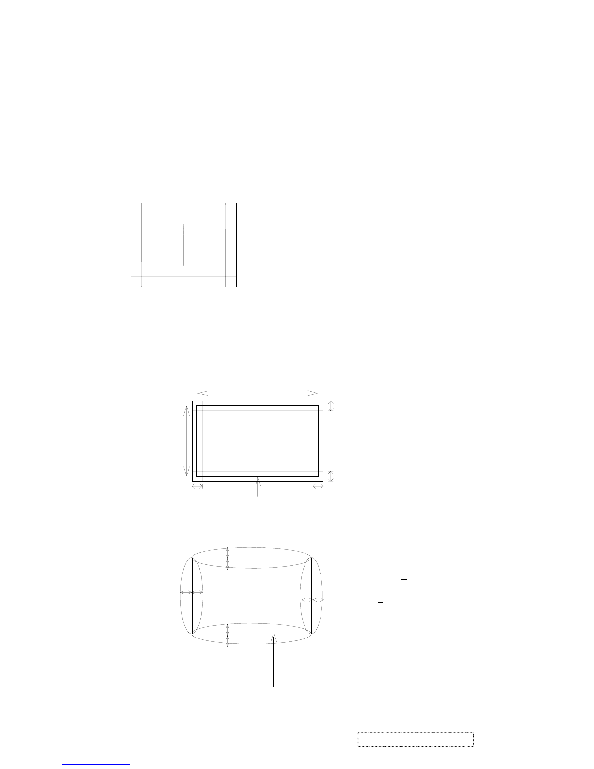
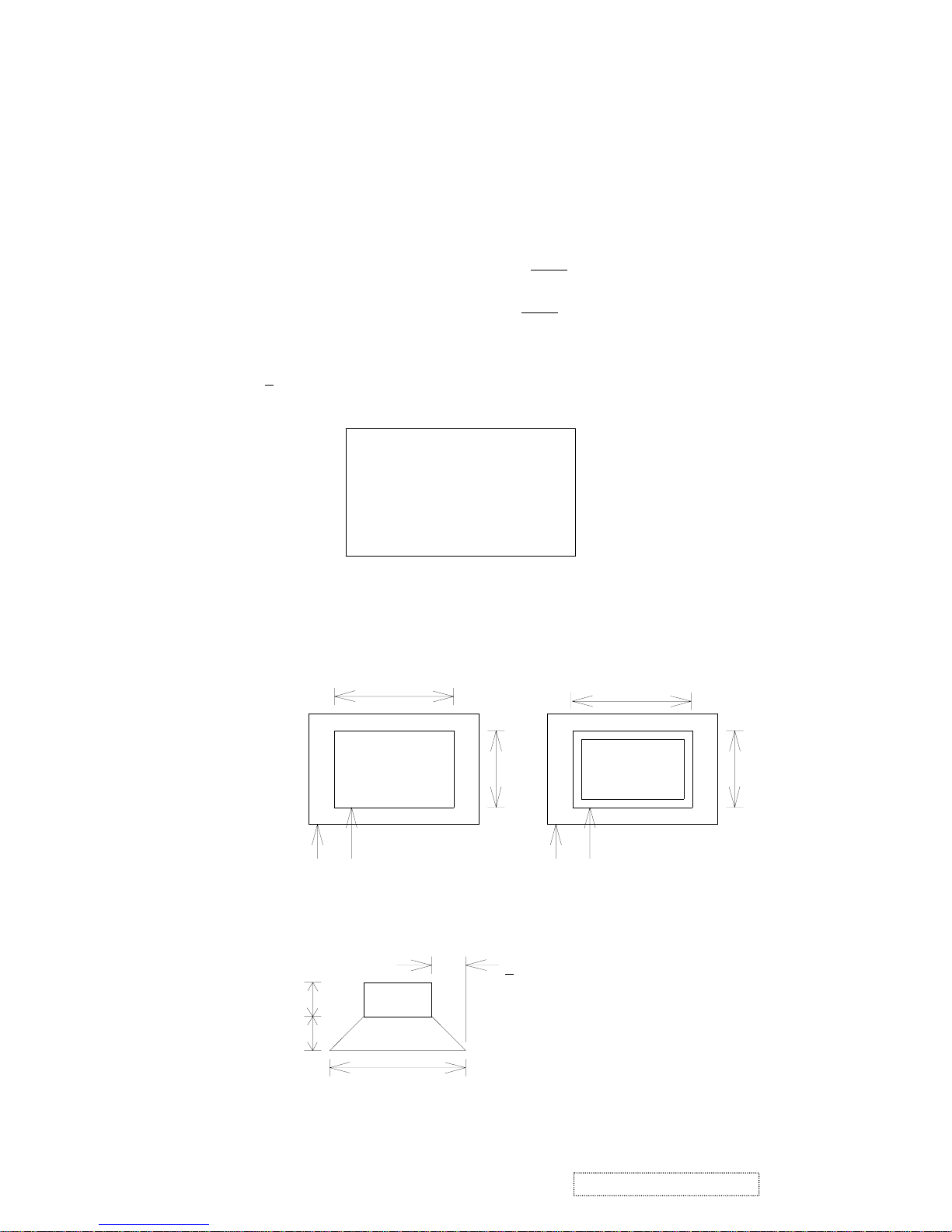
4.7 PICTURE DISTORTION
4.7.1 TRAPEZOID / PARALLELOGRAM
PICTURE
2mm
268mm
357mm
TRAPEZOID:
HORIZONTAL <= 2mm
VERTICAL <= 2mm
PARALLEL <= 2mm
2mm
2mm
2mm
4.7.2 PINCUSHION / BARREL / PIN-BALANCE
'
B'
C'
PICTURE
PINCUSHION <
BARLEL <
1.5mm
C
6
ViewSonic Corporation Confidential
-
Do Not Copy G90f/B-3

4.7.3 TILT
A
B
AA C 10
A
B
PICTURE
A - B <= 2mm
.
BEZEL
4.8 MISCONVERGENCE
PICTURE
357mm
268mm
ZONE A <= 0.25mm
ZONE B <= 0.30mm
B
ZONE C <= 0.35mm
C
A
4.9 FOCUS
4.9.1 UNDER THE CONDITION OF BRIGHTNESS CENTER AND CONTRAST MAXIMUM
“ ME “ PATTERN CAN BE SEEN CLEARLY BY USING THE 1280X1024 KHZ@85HZ
IF
NECESSARY, LIMIT SAMPLE AGREED BY BOTH PARTIES WILL BE MADE FOR
FINAL FOCUS JUDGMENT.
4.10 JITTERS
4.10.1 NO VISIBLE
4.11 WHITE BALANCE
4.11.1 COLOR TEMPERATURE USING THE CIE COLOR TEMPERATURE COORDINATE
SYSTEM
COLOR 9300
O
K X = 0.283±0.015; Y = 0.297±0.015
COLOR 6500
O
K X = 0.313±0.020; Y = 0.329±0.020
COLOR 5000
O
K X = 0.346±0.020; Y = 0.359± 0.020
4.11.2 COLOR PURITY IMPURITY SHOULD NOT APPEAR IN THE PATTERN OF ALL
GREEN ALL RED ALL BLUE OR ALL WHITE
4.11.3 COLOR TRACKING: WHEN THE FULL WHITE PATTERN IS DISPLAYED AT PRESET
(ONLY FOR 9300
O
K) CONDITION. THE DIFFERENCE OF WHITE BALANCE
BETWEEN CONTRAST 30 FL AND LOW CONTRAST 10 FL MUST BE LESS THAN
FOLLOWING VALUE
x AT CONTRAST 30 FL - x AT 25.75 FL < 0.005
y AT CONTRAST 30 FL - y AT 25.75 FL < 0.005
AND: x AT CONTRAST 25.75 FL - x AT 10 FL < 0.009
Y AT CONTRAST 25.75 FL - Y AT 10 FL < 0.009
7
ViewSonic Corporation Confidential
-
Do Not Copy G90f/B-3
4.11.4 VIDEO AMPLIFIER LINEARITY INPUT STEP AT 9300
O
K
x 600mV – x 700mV < 0.007
y 600mV – y 700mV < 0.003
4.12 LIGHT OUTPUT
AT 80 KHZ 1280X1024/75HZ MODE.
4.12.1 LL => AT BLACK PATTERN = 0.4 -1.2FL AT BRIGHTNESS 100%, CONTRAST 0%
FOR 9300
O
K
4.12.2 HL => AT WHITE BLOCK PATTERN = 37-43
FL AT BRIGHTNESS 50%, CONTRAST
100% FOR 9300
O
K
4.12.3 ABL => AT FULL-WHITE PATTERN 28-32
FL, BRIGHTNESS 50%, CONTRAST 100%
FOR 9300
O
K
4.13 BRIGHTNESS UNIFORMITY
4.13.1 >
75% MAXIMUM BETWEEN CENTER TO ANY EIGHT POINTS WITHIN THE
DISPLAY PICTURE FULL WHITE PATTERN
4.14 SIZE REGULATION
4.14.1 STATIC REGULATION
PICTURE GROWTH FROM MINIMUM LIGHT OUTPUT TO MAXIMUM LIGHT OUTPUT
SHALL BE LESS THAN 3mm WHEN PICTURE IS EXCHANGED FROM
4.14.2 DYNAMIC REGULATION
PICTURE GROWTH SHALL BE LESS THAN 1 mm WHEN PICTURE IS EXCHANGED
FROM
370mm
WHITE
BLACK100mm
100mm
< 1 mm
A
D
F
BC
E
HG
CENTER
PICTURE
BEZEL
BLACK WHITE
A
B
A'
B`
PICTURE
BEZEL
8
ViewSonic Corporation Confidential
-
Do Not Copy G90f/B-3

5. ENVIRONMENTAL CONDITIONS
5.1 TEMPERATURE AND HUMIDITY AT OPERATION 0 ~ 40
°C
5 – 95 % RH WITHOUT CONDENSATION
5.2 TEMPERATURE AND HUMIDITY AT STORAGE - 40 ~ 60
°
C
10 – 95 % RH LESS THAN
6
MONTH
5.3 VIBRATION TEST (PACKAGED)
FREQUENCY 5HZ –250 HZ – 5HZ
ACCELERATION 1.0G
SWEEP TIME 1 OCT/MIN.
TEST TIME 60MIN. / AXIS
5.4 DROP TEST (PACKAGED) 61 CM HEIGHT WEAK CORNER, 3 EDGES, 6 FACES, 1 TIME ON
EACH TESTED UNIT, 4 SETS MIN. DROP QTY.
5.5 ALTITUDE
OPERATING 0~3000 METERS.
NON-OPERATING 0~12000 METERS.
6. PHYSICAL SPECIFICATION
6.1 DIMENSION
HEIGHT: 457 mm
WIDTH 445 mm
DEPTH 456 mm
MONITOR WEIGHT 19.2 KG.
6.2 MECHANICAL ADJUSTMENT
TILT - 5/+15 DEGREES
SWIVEL
±
90 DEGREES
6.3 PACKAGING
6.3.1 CARTON DIMENSION
HEIGHT 498 mm
WIDTH 557 mm
DEPTH 577 mm
6.3.2 SHIPPING WEIGHT 22.4 KG
6.3.3 CONTAINER LOADING 320 UNITS WITH PALLET
9
ViewSonic Corporation Confidential
-
Do Not Copy G90f/B-3
7. FACTORY PRESET TIMINGS
7.1 TIMING DIAGRAM
TIMING OF INPUT SIGNALS NOMINAL INPUT LEVEL SPECIFICATION.
INPUT LEVEL
ANALOG VIDEO
RGB: 0.7V
±
3db
SYNC: H.V. SEPARATE SYNC
TTL COMPATIBLE H.V. COMPOSITA SYNC
LOW (0) 0V MIN. 0.65V MAX.
HIGH (1) 2.40V MIN. 3.5V NOM. 5.5V MAX.
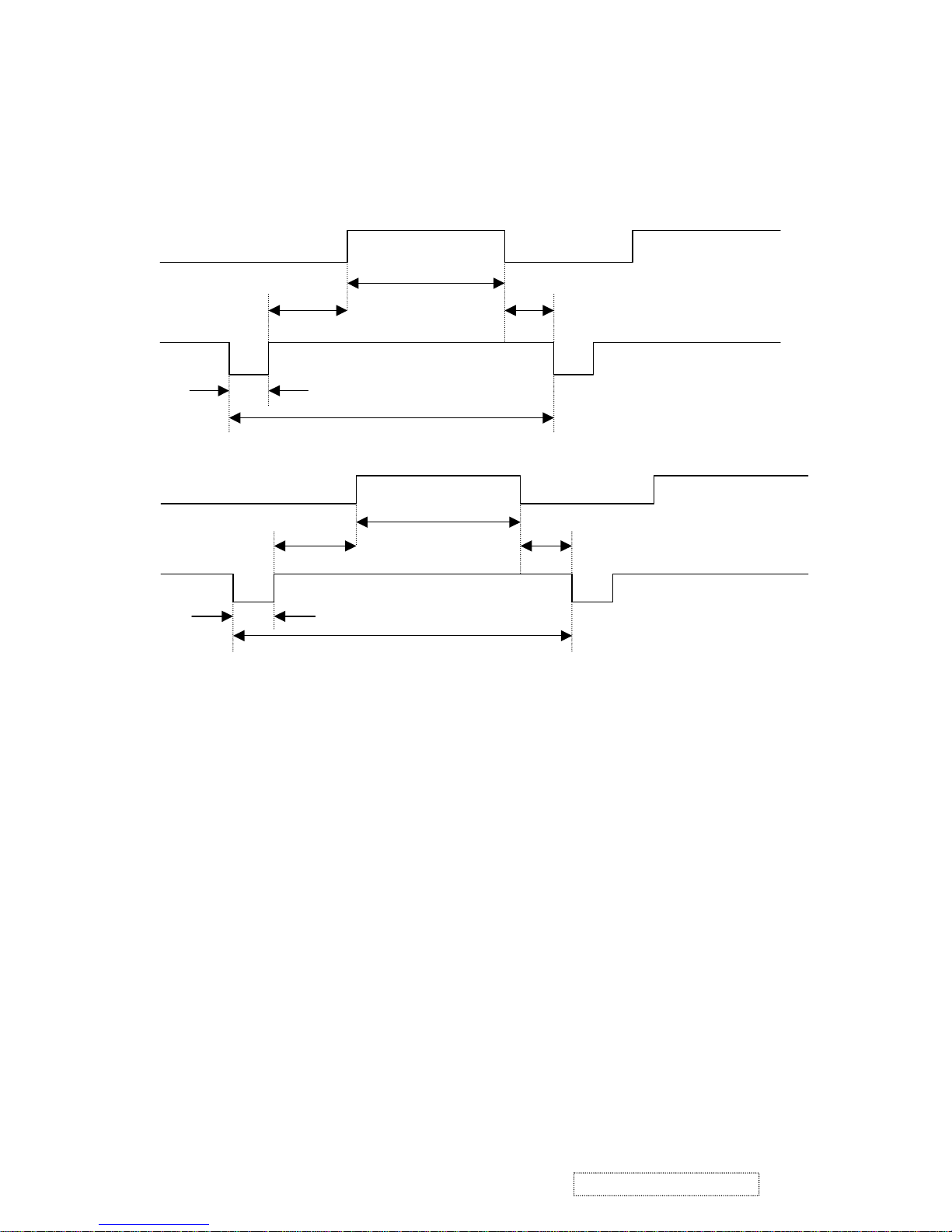
TIMING OF INPUT SIGNALS
A: H-TOTAL TIME O: V-TOTAL TIME
B: H-SYNC PULSE WIDTH P: V-SYNC PULSE WIDTH
C: H-BACK PORCH Q: V-BACK PROCH
D: H-DISPLAY TIME R: V-DISPLAY TIME
E: H-FRONT PORCH S: V-FRONT PORCH
VIDEO
C
D
E
B
A
VIDEO
Q
R
S
P
O
VERTICAL
10
ViewSonic Corporation Confidential
-
Do Not Copy G90f/B-3
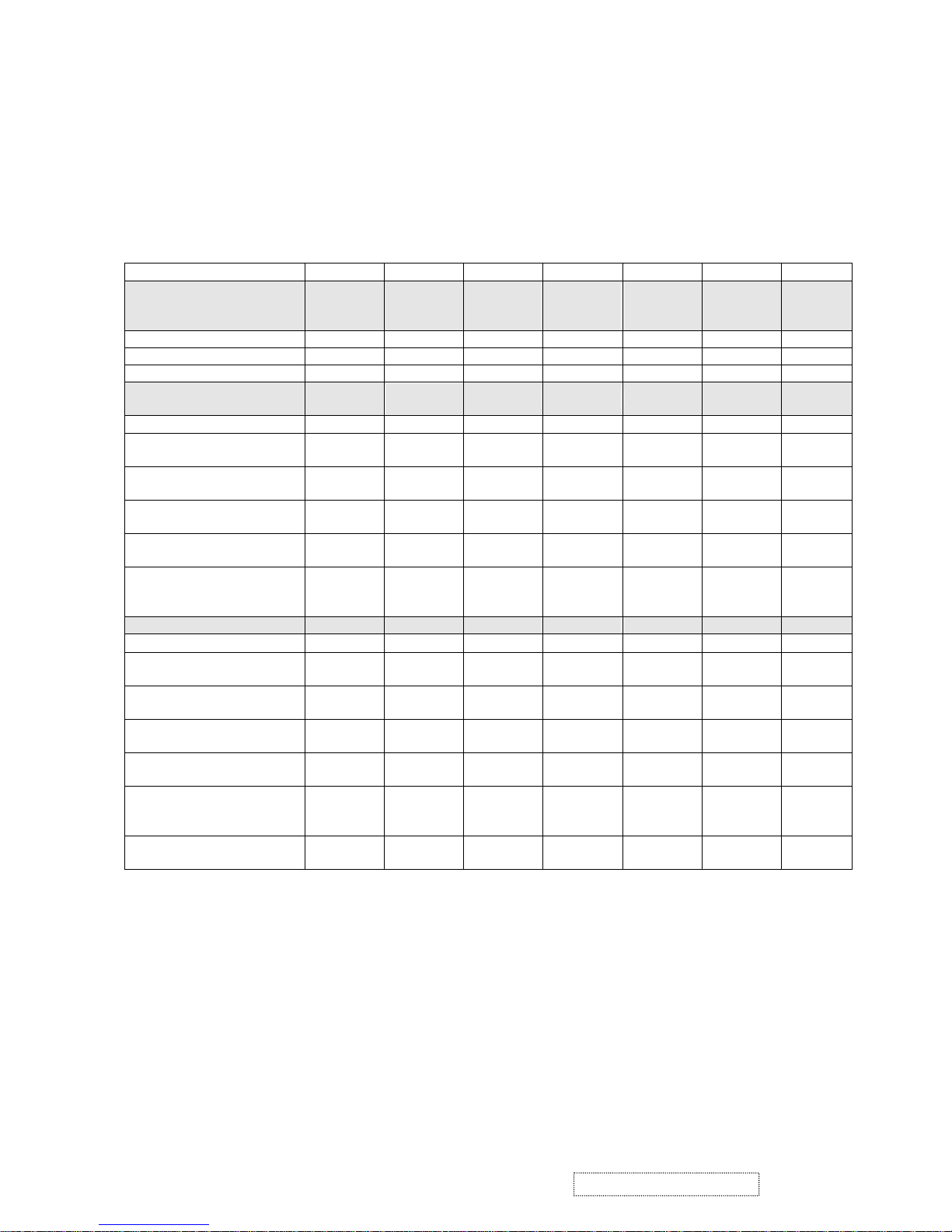
7.2 PRESET TIMING TABLE
PRESET TIMING TABLE
MODE NO. 1 2 3 4 5 6 7
MODE NAME
VGA
640X
480
VGA
640X
400
VGA
640X
480
VESA
800X
600
VESA
600
VESA
1024X
768
VESA
1024X
768
HORIZONTAL DOTS 640 640 640 800 800 1024 1024
VERTICAL LINES 480 400 480 600 600 768 768
PIXEL CLOCK (MHZ) 25.175 25.175 36.00 49.5 56.25 78.75 94.5
HORIZONTAL FREQ
(KHZ)
31.47 31.47 43.269 46.875 53.674 60.023 68.677
SYNC. POLARITY - - - + +
+
+
A H.TOTAL (US)
(PIXELS)
31.778
(800)
31.778
(800)
23.111
(832)
21.333
(1056)
18.631
(1048)
16.660
(1312)
14.561
(1376)
B H.SYNC (US)
(PIXELS)
3.813
(96)
3.813
(96)
1.556
(56)
1.616
(80)
1.183
(64)
1.129
(96)
1.016
(96)
C H.SYNC PORCH (US)
(PIXELS)
1.907
(48)
1.907
(48)
2.222
(80)
3.232
(160)
2.702
(152)
2.235
(176)
2.201
(208)
D H.ACTIVE (US)
(PIXELS)
25.422
(640)
25.422
(640)
17.778
(640)
16.162
(800)
14.222
(800)
13.003
(1024)
10.836
(1024)
E H.FRONT PORCH
(US)
(PIXELS)
0.636
(16)
0.318
(8)
1.556
(56)
0.323
(16)
0
(0)
0.203
(16)
0
(0)
VERTICAL FREQ (HZ) 59.94 70 85.008 75.00 85 75.029 85
SYNC. POLARITY - + - + +
+
+
O V.TOTAL (MS)
(LINES)
16.684
(525)
14.268
(449)
11.764
(509)
13.333
(625)
11.756
(631)
13.328
(800)
11.765
(808)
P V.SYNC (MS)
(LINES)
0.064
(2)
0.064
(2)
0.069
(3)
0.064
(3)
0.056
(3)
0.050
(3)
0.044
(3)
Q V.BACK PORCH (MS)
(LINES)
1.048
(33)
1.112
(35)
0.578
(25)
0.448
(21)
0.503
(27)
0.466
(28)
0.524
(36)
R V.ACTIVE (MS)
(LINES)
15.254
(480)
12.711
(400)
11.093
(480)
12.800
(600)
11.179
(600)
12.795
(768)
11.183
(768)
S V.FRONT PORCH
(MS)
(LINES)
0.318
(10)
0.222
(7)
0.023
(1)
0.021
(1)
0
(0)
0.017
(1)
0
(0)
SCANTYPE
INTERLACED
NO NO NO NO NO NO NO
31.47
11
ViewSonic Corporation Confidential
-
Do Not Copy G90f/B-3

PRESET TIMING TABLE (CONTINUOUS)
MODE NO. 8 9 10 11 12
MODE NAME
MAC
1024X
768
MAC
1152X
870
VESA
1280X
1024
VESA
1280X
1024
VESA
1600X
1200
HORIZONTAL DOTS 1024 1152 1280 1280 1600
VERTICAL LINES 768 870 1024 1024 1200
PIXEL CLOCK (MHZ) 80 100 135.00 157.5 202.5
HORIZONTAL FREQ (KHZ) 60.241 68.681 79.976 91.146 93.75
SYNC. POLARITY
−
-
+
+
+
A H.TOTAL (US)
(PIXELS)
16.600
(1328)
14.56
(1456)
12.504
(1688)
10.971
(1728)
10.667
(2160)
B H.SYNC (US)
(PIXELS)
1.200
(96)
1.280
(128)
1.067
(144)
1.016
(160)
0.948
(192)
C H.SYNC PORCH (US)
(PIXELS)
2.20
(176)
1.44
(144)
1.837
(248)
1.422
(224)
1.501
(304)
D H.ACTIVE (US)
(PIXELS)
12.8
(1024)
11.52
(1152)
9.481
(1280)
8.127
(1280)
7.901
(1600)
E H.FRONT PORCH (US)
(PIXELS)
0.4
(32)
0.32
(32)
0.119
(16)
0.406
(64)
0.361
(64)
VERTICAL FREQ (HZ) 74.927 75 75.025 85.024 75
SYNC. POLARITY
−
-
+ − +
O V.TOTAL (MS)
(LINES)
13.346
(804)
13.322
(915)
13.329
(1066)
11.761
(1072)
13.333
(1250)
P V.SYNC (MS)
(LINES)
0.050
(3)
0.044
(3)
0.038
(3)
0.033
(3)
0.032
(3)
Q V.BACK PORCH (MS)
(LINES)
0.498
(30)
0.568
(39)
0.475
(38)
0.483
(44)
0.491
(46)
R V.ACTIVE (MS)
(LINES)
12.749
(768)
12.667
(870)
12.804
(1024)
11.235
(1024)
12.800
(1200)
S V.FRONT PORCH (MS)
(LINES)
0.05
(3)
0.044
(3)
0.013
(1)
0.011
(1)
0.011
(1)
SCANTYPE INTERLACED NO NO NO NO NO
12
ViewSonic Corporation Confidential
-
Do Not Copy G90f/B-3

EDID DATA for SAMSUNG CRT:
______________________________________________________________________
VIEWSONIC CORPORATION
EDID VERSION # 1, REVISION # 3
DDCTEST FOR: VIEWSONIC G90F-3
______________________________________________________________________
______________________________________________________________________
128 BYTES OF EDID CODE:
0 1 2 3 4 5 6 7 8 9
________________________________________
0 | 00 FF FF FF FF FF FF 00 5A 63
10 | 1A C9 01 01 01 01 01 0E 01 03
20 | 1D 24 1B BE 2A BB B8 A3 52 46
30 | 98 24 0F 48 4C FF FF 80 81 99
40 | D1 40 A9 4F 61 59 45 59 31 59
50 | 01 01 01 01 86 3D 00 C0 51 00
60 | 30 40 40 A0 13 00 60 08 11 00
70 | 00 1E 00 00 00 FF 00 50 45 47
80 | 30 34 30 31 30 30 30 30 31 0A
90 | 00 00 00 FD 00 32 B4 1E 61 18
100 | 00 0A 20 20 20 20 20 20 00 00
110 | 00 FC 00 47 39 30 66 2D 33 0A
120 | 20 20 20 20 20 20 00 8E
13
ViewSonic Corporation Confidential
-
Do Not Copy G90f/B-3
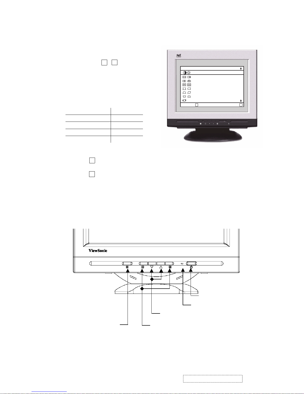
A﹒User control﹒
Power switch:Soft power control﹒
Function select button: , ﹒
Adjustment control button
:▽﹑△﹒
Control name﹒
1. Power switch:Push-on / push-off switch for soft
power control﹒
2. LED indication
Status LED
Power on Green
Off mode in 5 sec Orange
Over range freq. Orange
Power off Off
3﹒Function select button:
Press the ‘ ’ button to display OSD menu.
Press the ‘
▽﹑△
’ button to select menu function or sub-function.
Press the ‘ ’ button to enter the select function.
4﹒Adjustment control button:
Push the increased ‘△’ or decrease ‘▽’ button for the desired adjustment﹐all adjustment are memorized
automatically immediately﹒
1
2
1
2
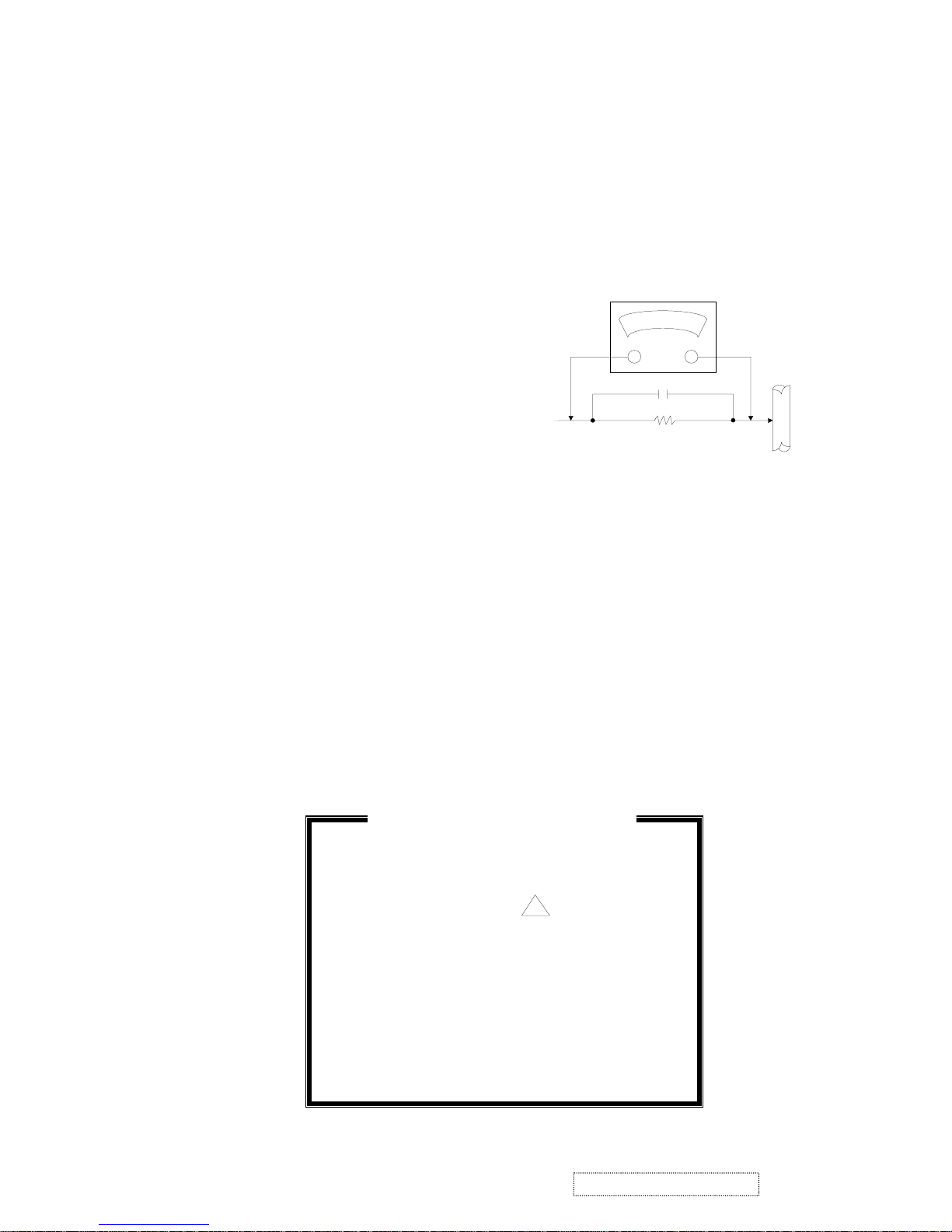
a. Power switch
b. Power-On indication
c. Adjustment control buttons
d. Function select buttons
e. Auto sizing
3. Front Panel Function Control Description
1 2
ViewSonic
MAIN MENU 1
EXIT :
SELECT :
CONTRAST/BRIGHTNESS
H. SIZE / POSITION
V. SIZE / POSITION
ZOOM
PINCUSHIO / BALANCE
TRAPEZOID / PARALLEL
TOP / BOTTOM HOOK
TILT
1
2
14
ViewSonic Corporation Confidential
-
Do Not Copy G90f/B-3

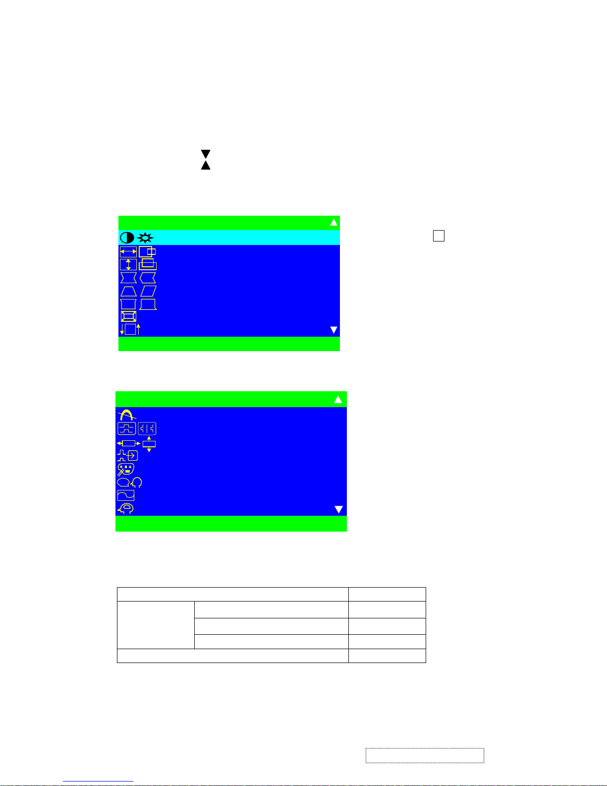
B. OSD (on screen display) function control method.
. Main menu, Part 1.
1. Contrast / Brightness.
2. H. size / Position.
3. V. size / Position.
4. Pincushion / Balance.
5. Trapezoid / Parallel.
6. Top/Bottom Hook.
7. ZOOM
8. Tilt
. Main menu, Part 2.
9. Degauss
10. H/V Moire.
11. OSD Position.
12. Input Level.
13. View match color.
14. Language.
15. View meter.
16. Memory Recall.
15
ViewSonic Corporation Confidential
-
Do Not Copy G90f/B-3
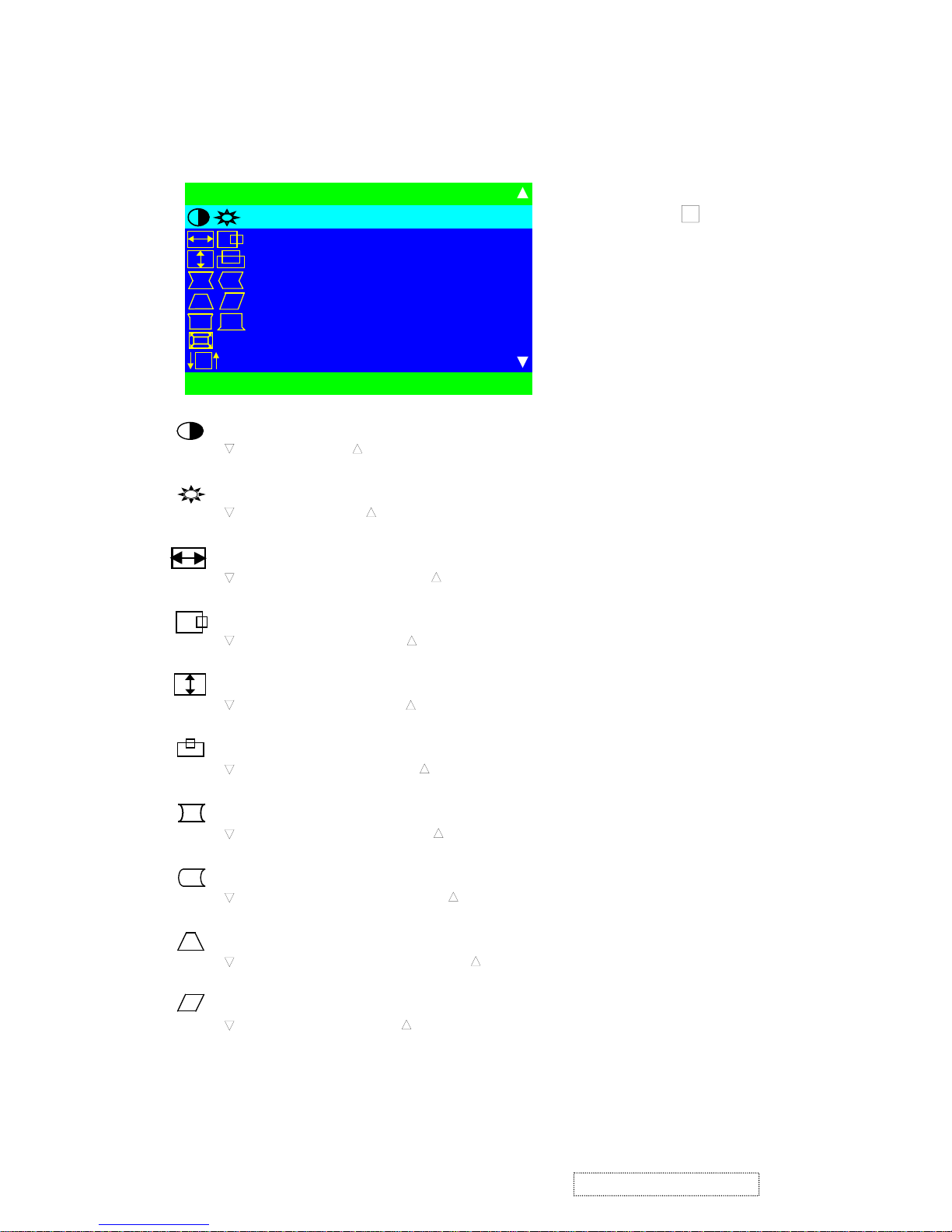
OSD function control :
Main menu, part1
Note
:
Press button to toggle between
all Controls that appear in pairs on the
Main menu1.
Contrast adjusts the foreground white level of the screen image.
decreases contrast, increases contrast.
Brightness adjusts the background brightness of the screen image.
decreases brightness, increases brightness.
HORIZONTAL SIZE adjusts the width of the screen image.
decreases width of screen image, increases width of screen image.
HORIZONTAL POSITION moves the screen image left or right.
moves the screen image left, moves the screen image right.
VERTICAL SIZE
adjusts the height of the screen image.
decreases the screen height, increases the screen height.
VERTICAL POSITION moves the screen image up and down.
moves the screen image down, moves the screen image up.
PINCUSHION straightens the vertical sides of the screen image by curving them inward or out ward.
curves the vertical edges inward, curves the vertical edges outward.
PIN BALANCE straightens the vertical sides of the screen image by curving them to the right or to the left.
curves the vertical edges to the left, curves the vertical edges to the right.
TRAPEZOID make vertical sides of the screen image parallel.
narrows the top and widens the bottom, widens the top and narrows the bottom.
PARALLEL (parallelogram) slants vertical edges of the screen to the left or right.
slants vertical edges to left, slants vertical edges to right.
2
MA I N ME N U 1
CONTRAST / BR IGHTNESS
H.SI ZE/POSIT ION
V.SIZE/POSITION
P I NCUSH I ON / BA L ANCE
TRAPEZO I D / PARALLEL
TOP / BOT T OM HOOK
ZOOM
TILT
EX I T : 1 SELECT :2
16
ViewSonic Corporation Confidential
-
Do Not Copy G90f/B-3
TOP HOOK
Straightens the top corners of the screen image. [▽] or [△] to adjust.
BOTTOM HOOK
Straightens the bottom corners of the screen image. [▽] or [△] to adjust.
ZOOM CONTROL
to diminish H-Size
& V-Size, △ to enlarge H-Size & V-Size.
TILT
rotates the entire screen image.
rotates the screen counter-clockwise, rotates the screen clockwise.
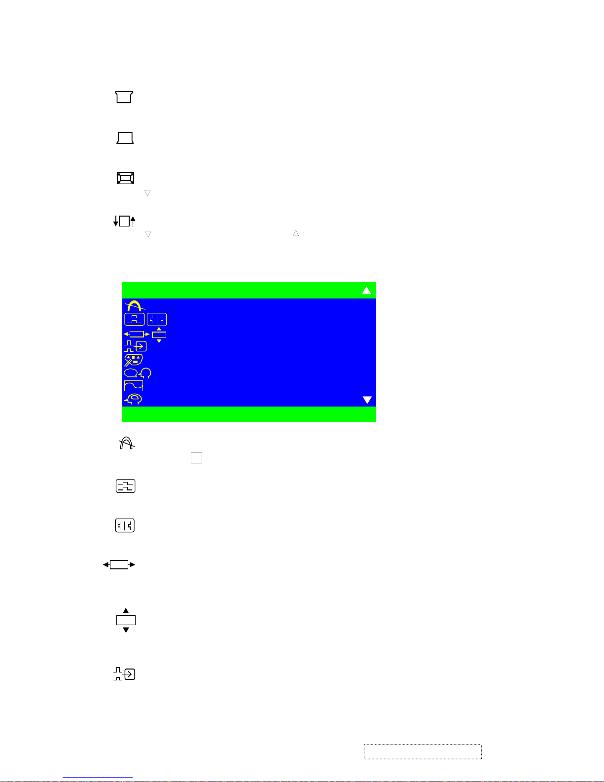
Main menu, part12
MA I N ME N U 2
DEGAUSS
H/V MOIRE
OSD POS I T I ON
I NPUT LEVEL
VIEWMATCH COLOR
LANGUAGE
VIEWMETER
MEMORY RECAL L
EX I T : 1 SELECT : 2
OSD
OSD
?
DEGAUSS manual degauss function.
Press button to active manual degauss function.
H MOIRE reduces vertical interference that causes unwanted color textures or patterns.
Press
▽
or △ to adjust.
V MOIRE reduces horizontal interference patterns that causes unwanted color textures or patterns.
Press
▽
or △ to adjust.
OSD H-Position control
Press the
▽, △ button.
▽ move OSD to left side, △ move OSD to right side﹒
OSD V-Position control
Press the ▽, △ button.
△
move OSD to up, ▽ move OSD to down.
INPUT LEVEL displays the voltage level of the video signal.
2
OSD
OSD
17
ViewSonic Corporation Confidential
-
Do Not Copy G90f/B-3
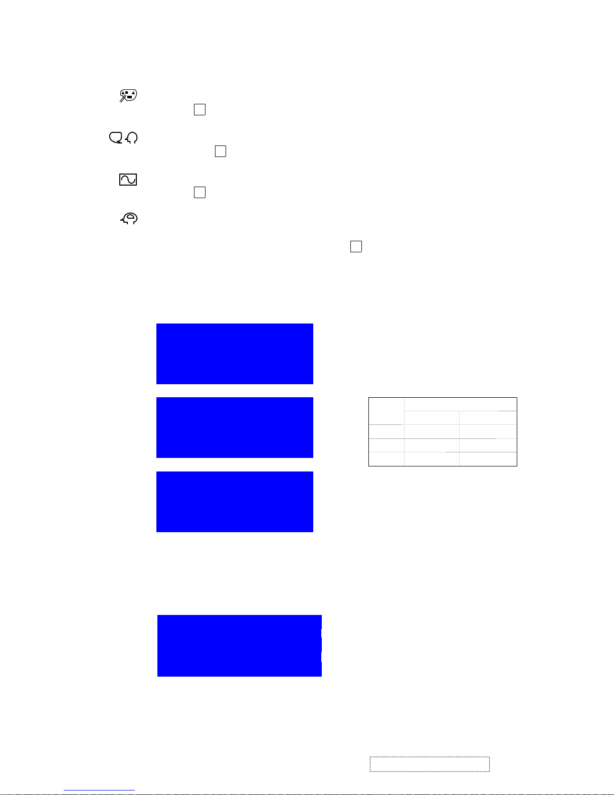
VIEWMATCH COLOR provides three color adjustment modes : 9300oK, 6500oK, 5000 oK and User.
Press button to select color adjustment mode.
LANGUAGE to select a language use
▽
and △ to highlight English, French, German, Italian, or Spanish,
Then press button .
VIEWMETER displays the signal input coming from your computer (horizontal scan and refresh rate).
Press button to select this feature.
MEMORY RECALL
returns adjustment back to factory setting only if the monitor is operating in a factory
preset mode.
If you make an adjustment you don’t like, press button to recall factory setting.
DIAGNOSTIC
1.If monitor into DPMS mode will show:
Display Time : 5 seconds
Back ground
: Blue
Characters
: White
Horizontal
2.If input V-sync or H-sync out of pull-in range will show:
H:30KHz ~ 96KHz
V:50Hz ~ 180Hz
Display Time
Pull-in range
Back ground
: Blue
Characters : White
Signals
Vert
ical
: 25 seconds
Off mode in 5
OFF MODE IN 5 SEC
OFF MODE IN 5 SEC
OFF MODE IN 5 SEC
2
2
?
2
2
18
ViewSonic Corporation Confidential
-
Do Not Copy G90f/B-3
1. POWER SUPPLY
1.1 Power
supply
A﹒ Primary Side﹒
The raw DC voltage is built on C101 from AC line voltage through EMI filter﹐and bridge rectifier CR101﹐then
composes with main transformer(T101)﹐switching MOSFET(Q101)and PWM IC(IC101)to form a DC-DC
voltage converter by fly back switching topology, which means that the power energy is pumped up at primary
winding of transformer during duty “ON” cycle﹐then transfer the stored energy to primary side﹐and voltage
regulated by PWM IC(VC3843B)using way of pulse width modulation﹒
The IC101 starts up through some components composed of R103﹐R104﹐R105﹐Q102﹐ZD101 D110.R118.
R107 to build up VCC voltage at pin7﹐and supplied by transformer once secondary voltage is established﹒
IC101 have to work synchronously with horizontal sync by feeding fly back pulse through C110﹒
R124 .R125, C112 and D114 composed a soft-start circuit to prevent over-stress occurred during power start﹒
The TP202:40V voltage can be adjusted through VR101﹒
B﹒ Secondary
Each raw of DC voltage output from T101﹒
a﹒ TP201 voltage output from T101 pin9 and is rectified by D202﹐C201﹒
b﹒ TP202 voltage output from T101 pin14 and is rectified by D203﹐D214. C202﹒
c﹒ TP203 voltage output from T101 pin15 and is received by D205﹐C205﹒
d﹒ TP204 voltage output from T101 pin16 and is rectified by D206﹐C206﹒
e﹒ TP205 voltage output from T101 Pin15 and is rectified by Q206﹐ZD201 and D208.C210. ﹒
f﹒ TP206 voltage output from TP204 and is rectified by Q208.Q209.﹐R214. R215.and R213﹒
g﹒ TP207 voltage output from T204﹒and is rectified by Q210 ZD202 D209 R217.C211and C212.
1.2 Power saving
The EPA power management state as follows:
State SUS Pd Power consummation LED
Normal H H 100W Green
Active off L L ≤ 4W Amber
PD = IC301(MCU)pin17 output﹒
There is no output from Q206 and Q203 while is in Active off mode and PD(IC301 pin17)is low level
voltage﹒That is, there is no output for 12V and 6.3V﹒
1.3 Degauss
When the powers is on and when press manual degauss﹐IC301 pin20 output high level voltage to turn on
Q201﹐RL101 and activate Degauss﹒
4. Circuit Description
19
ViewSonic Corporation Confidential
-
Do Not Copy G90f/B-3

2. H and V processor
2.1 Auto Sync Deflection control and B+ control circuit Horizontal and vertical sync through IC401 STV9118
transmit﹒
Deflection controller IC401 STV9118:
a﹒ The control input(V-position﹐H-position﹐V- si ze ﹐H-size﹐Pincushion﹐Pin-Balance﹐Trapezoid﹐
Parallelogram. TOP Corner. Bottom Corner. Zoom, moiré)are use I
2
C control﹒
b﹒ SYNC input:
H-sync(pin1)(From IC301 pin33)﹒
V-sync(pin2)(From IC301 pin32)﹒
c﹒ Output:
∗ B
+
Driver(pin28)﹒
∗ H-Driver(pin26)﹒
∗ EW-Driver(pin24)﹒
∗ Focus(pin32)﹒
∗ V out(pin23)﹒
2.1.1 Horizontal input control
a﹒ Then take a HFLB pulse from FBT pin5 to IC401 for AFC to make pin 26 H-driver output
control Horizontal circuit﹒
b﹒ Pin 6 and pin 8(C429﹐R471)control horizontal hold in range﹒
2.1.2 Vertical input control
a. V-sync outputs from MCU IC301 pin32 to IC401 pin2﹐then release V-out from pin23﹐pin 13 to
IC501 KA2142 pin1and pin7﹒
b. V-output to vertical hold in range is controlled by pin22(C508)﹒
2.1.3 B
+
input control
Take a pulse from T401 pin 5 and accumulates to become a DC voltage via D423﹐C437 and R4408
to IC 401 pin14, pin15 output pulse by pin28 via Q202 to boost converter circuit.
2.2 Vertical deflection
a﹒ IC401 pin23 and pin13 output to IC501(KA2142)pin7 and pin1﹐then IC501 pin 6 make vertical
deflection output﹒
b﹒ Vertical blank:IC501 pin4 take a blanking pulse﹐After passing Q501 buffer can supply video blanking
signal﹒
2.3 Boost converter
The Booster converter mainly composes of n-channel MOSFET Q202 chock L201 capacitor C202, C212 and
rectifier diode D204. IC401 pin28 B
+
driver output via Q204, Q205, Q202 to driver Booster converter
and provide a DC-voltage to provide B
+
H-output circuit use﹐As H-freq. change﹐IC401 pin28 B+-driver
will change its output﹐Booster converter will also change the B
+
it provides﹐H-freq. will varies from
30K ~ 96KHz﹐B+ will varies from 55V ~ 195V﹒
2.4 X-RAY radiation protection
FBT pin 5 output one pulse to pass through D417 and C424 integration DC voltage﹐and through D418 IC401
pin 25﹐when anode voltage abnormal increase﹐FBT pin5 and IC401 pin25 voltage to be increased﹐too﹒
As IC401 pin25 ≅8V﹐IC401 X-RAY protection circuit immediately active﹐H-driver, B-driver and V-out no
output﹒The X-RAY radiation protection circuit used in this monitor is a latching type the monitor will shown
down and continue until turn-off the monitor with power switch﹒
20
ViewSonic Corporation Confidential
-
Do Not Copy G90f/B-3

3. Horizontal
3.1 Horizontal driver circuit
The output of IC401 pin26 H-Driver connect to Q402 H-driver transistor makes Q402 active ON/OFF, push
H-output Q401 to reach secondary via induction of T402﹒For T402 is a Transformer of reduced voltage and
converted pole﹐Q401 will be turn off when Q402 is on﹐on the contrary﹐went Q402 is turn off and Q401
will be on﹒
3.2 Horizontal output circuit
Horizontal output circuit is composed by Q401(Horizontal Transistor)﹐T401(FBT), D402, D403, C401 and
C416 H-output circuit﹐H-Driver circuit output via T402 to switch Q401 ON/OFF to output saw tooth wave and
make DY able to control the circuit scanning of elections in the CRT﹒
L404﹐C414﹐C415﹐modify Horizontal linearity switching individually Via Q414 ﹒
3.3 EW-Pincushion and width control circuit
The parabolic waveform and DC voltage and generated from IC401 pin24 to Q411, Q412 and Q409﹒
The parabolic decreased or increased for compensating the pincushion effect the DC voltage control the
H-width ﹒
4. Video
4.1 Video amplifier(IC601)
The video amplifier module is composed of three amplifiers for Red﹐Green﹐Blue channel﹒
The video input signal is fed to the video preamplifier IC601(NT6813K)pin5 Blue﹐pin6 Green﹐pin7 Red﹐
through AC coupling capacitor﹐C601﹐C602﹐C603﹒
The clamping pulse comes from IC301 pin33﹒
IC603 output amplifier for B﹑R﹑G channel respectively﹒
4.2 On Screen Display(OSD)(IC602)﹒
IC601(NT6813K)is a on screen display generator, pin28 for H-sync input﹐pin10 for V- sync input﹒
The IC601 is controlled by IC301 via SCL﹐SDA bus IC602(pin11﹐pin12)﹒
4.3 Auto Beam Limit CKT(ABL CKT)﹒
When beam current pass through R447 over 500uA﹐the voltage build at base of Q418 will be low enough to
turn on Q418﹐then the voltage of pin26 of IC601 will be pulled down accordingly to reduce the video
preamplifier gain output﹒
4.4 Brightness Control
Brightness is controlled by varying the DC voltage of G1 with the IC301 PIN1(PWM)﹒
`
4.5 Blanking
IC501(KA2142)pin4 vertical blanking pulse are fed to the base of Q501﹐The blanking pulse O/P is coupled to
G1 by C507﹒
Horizontal blanking pulse are fed to IC601 pin28 and let video O/P amp cut off during the period of horizontal
retrace.
4.6 Mute.
While mode change﹐IC301 pin16 will pull high to turn off﹒The G1 voltage will down to –180V then CRT will
cut off the video output ﹒
21
ViewSonic Corporation Confidential
-
Do Not Copy G90f/B-3
6﹒ Micro(IC301)
6.1 H. sync / V. sync Processor﹒
HS/VS input pin39(HS)﹐pin40(VS)﹐IC301 individually to work on frequency﹐polarity﹐process of H+V
and power saving﹐then output horizontal sync(pin33)and vertical sync(pin32)of positive polarity to
IC401 STV9118 pin1﹐pin2﹒
6.2 PWM Control
The PWM control of IC301 is pin29(Brightness) and pin18(Rotation)﹐the PWM output via R﹐C after
rectified may control each function﹒
6.3 Power saving / Mute / LED control
IC301 pin17﹐pin18 are power saving control pin﹐the condition of power saving and mode change﹐pin19 will
change from Low to Hi and active Mute function﹒
Normal Active
Mute L H
PD H L
(Off mode)
IC301 pin17(PD)function as LED control﹐the mode is as listed:
Power On Power saving Over range freq﹒
Pin17 Hi Low Low
6.4 CS control(CS1 ~ HS2)
To count H-SYNC by the output frequency﹐then output the cumulating as listed:
Freq. CS1 CS2 CS3 CS4 HS1 HS2
< 33K 0 0 0 0 0 0
33K~36K 0 0 1 1 0 0
36K~41K 1 0 0 0 0 0
41K~45K 1 0 1 1 0 0
45K~51K 0 1 0 0 0 0
51K~57K 0 1 0 1 0 0
57K~61K 0 1 1 1 0 1
61K~66K 1 1 0 0 0 1
66K~71K 1 1 0 0 0 1
71K~78K 1 1 1 0 1 1
78K~83K 1 1 1 0 1 1
83K~89K 1 1 1 1 1 1
> 89K 1 1 1 1 1 1
5﹒ Tilt
IC301 pin18 PWM to tilt circuit﹐Q211 and Q213 control flow of current of Rotation coil﹐when the base of
C215 increase from 0 to 12V﹐As Q211 will turn on gradually﹐the current starts from 14V to 6.3V via Rotate
coil﹒When C215decrease from 12V to 0V﹐the current will change from 7V to GND﹒
6.5 Key Control﹕IC301 pin26~pin29 function as DAC switch input to control OSD display function﹒
Pin40: ﹒
Pin38:▽﹒
Pin37
:△﹒
Pin39: ﹒
6.6 I
2
C Bus
IC301 have two groups I
2
C bus to control E2PROM﹐IC401 deflection IC﹐Auto alignment﹐IC601 pre-AMP﹒
1
2
22
ViewSonic Corporation Confidential
-
Do Not Copy G90f/B-3
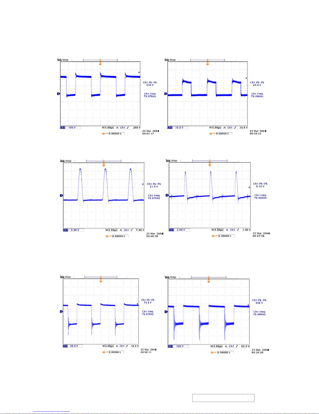
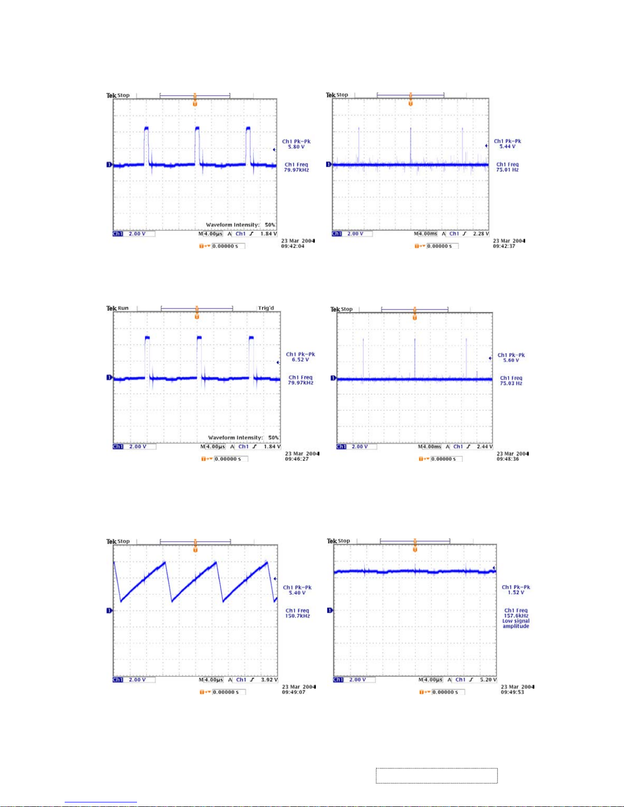
Waveform
(1) (2)
(3) (4)
(5) (6)
23
ViewSonic Corporation Confidential
-
Do Not Copy G90f/B-3
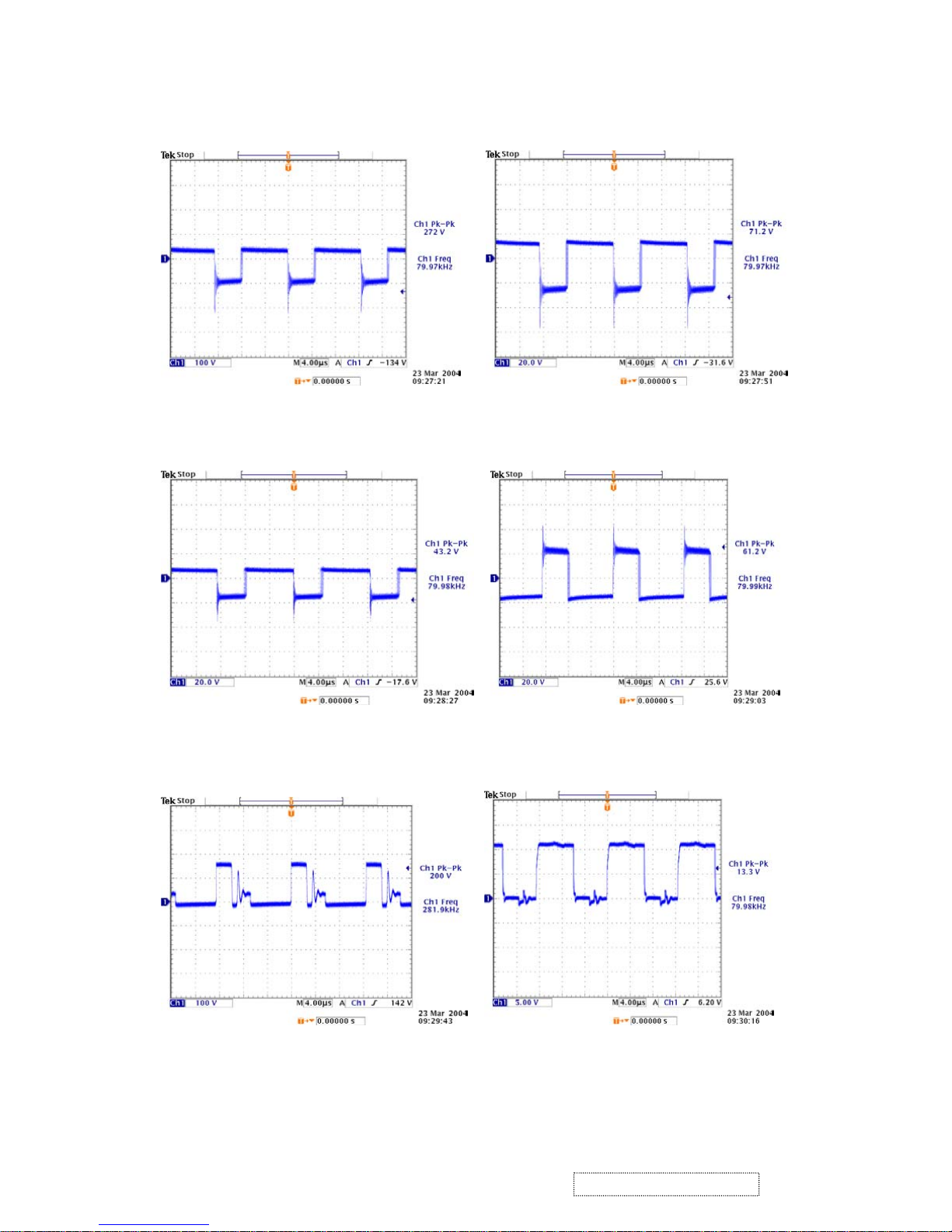
(7) (8)
(8) (10)
(11) (12)
24
ViewSonic Corporation Confidential
-
Do Not Copy G90f/B-3
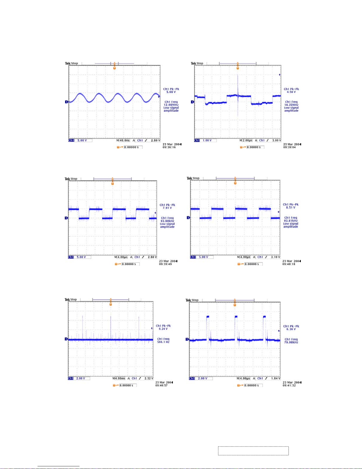
(13) (14)
(14) (16)
(17) (18)
25
ViewSonic Corporation Confidential
-
Do Not Copy G90f/B-3
(19) (20)
(20) (22)
(23) (24)
26
ViewSonic Corporation Confidential
-
Do Not Copy G90f/B-3

(25) (26)
(26) (28)
(29) (30)
27
ViewSonic Corporation Confidential
-
Do Not Copy G90f/B-3
 Loading...