

Page 1
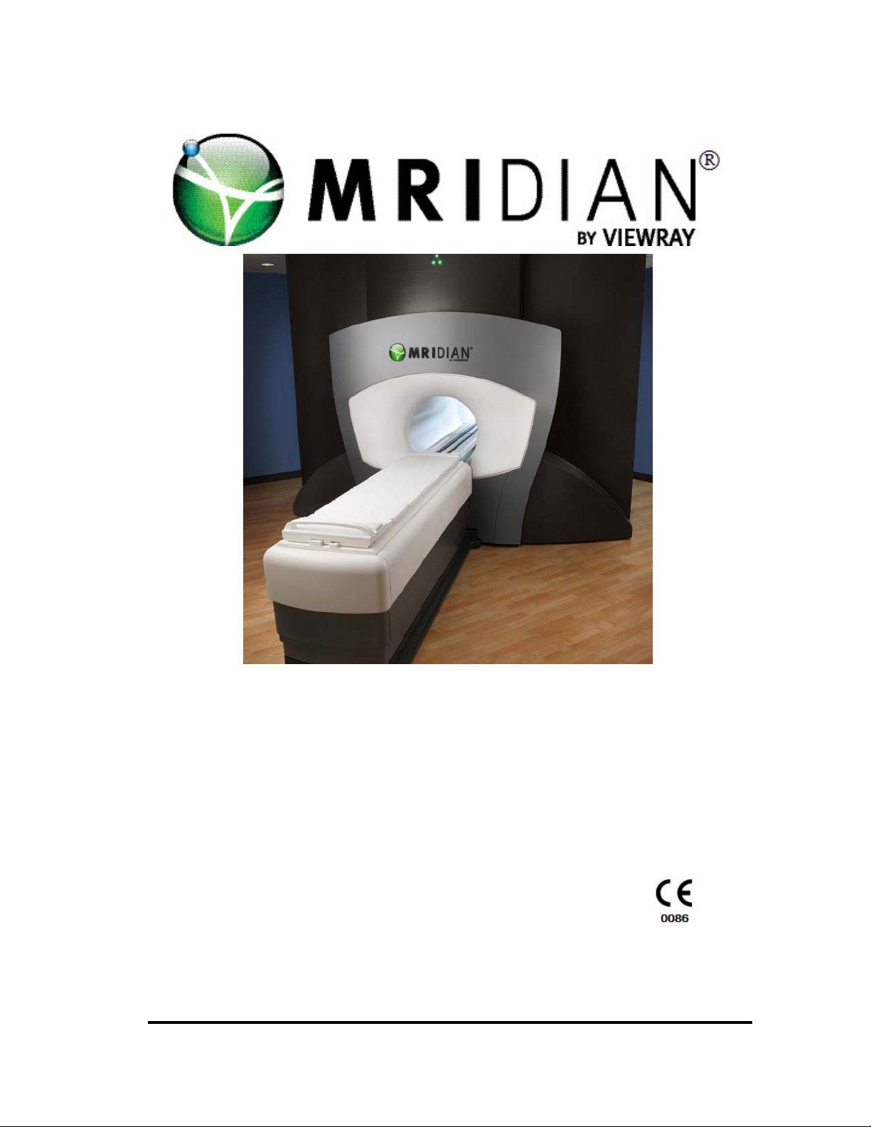
Operator’s Manual
for the
MRIdian® System 4.5
For Software Release 4.5
November 2016
Document No. L-0009
This document contains the confidential and proprietary information of ViewRay, Inc. Neither
this document nor any of the information contained is to be reproduced, distributed, used or
disclosed, either in whole or in part, except as specifically authorized by ViewRay, Inc.
Page 2

This page intentionally left blank.
Page 3

Copyright Statement
Copyright © 2016 ViewRay, Inc. All rights reserved. No part of this manual may be
photocopied, reproduced or translated into another language without written permission
from ViewRay, Inc.
ViewRay, Inc., has taken care to ensure the accuracy of this document; however, ViewRay Inc.
assumes no liability f
further notice to any products herein to improve reliability, function or design.
ViewRay provides this manual without warranty of any kind, either implied or expressed,
including
particular purpose.
This document contains proprietary information that is protected by copyright. ViewRay Inc.
eserves the right to revise this publication and to make changes in content from time to time
r
without obligation on the part of ViewRay to provide notification of such revision or change.
but not limited to, the implied warranties of merchantability and fitness for a
or errors or omissions and reserves the right to make changes without
Additional Manuals
To download a PDF of this manual visit www.viewray.com/resource_center_home and sign in
with your username and password.
Trademark Information
ViewRay is a trademark of ViewRay, Inc.
MRIdian is a trademark of ViewRay, Inc.
Windows
names are trademarks or registered trademarks of their respective holders.
® is a registered trademark of Microsoft® Corporation. Other brand or product
Patent Information
The MRIdian® system is protected by one or more patents.
Visit www.ViewRay.com/patents for a complete list of MRIdian system patents.
ViewRay Inc. MRIdian® system L-0009 Release 4.5 i
Page 4

Contacting Support
Support services are available without charge during the initial warranty period.
For service:
Telephone—1.855.286.8875
To submit system issues or product improvement requests online:
www.viewray.com/resource_center_service
European Authorized Representative:
MedPass International Ltd.
Winsor House Bretforton
Evesham, Worcestershire.
WR11 7JJ, United Kingdom
ii MRIdian® system L-0009 Release 4.5 ViewRay Inc.
Page 5
CAUTION: The MRIdian® system is for PRESCRIPTION USE ONLY. Federal
law restricts the device to sale by or on the order of a physician, or
licensed healthcare provider.
Intended Use
The MRIdian system, with magnetic resonance imaging capabilities, is intended to provide
stereotactic radiosurgery and precision radiotherapy for lesions, tumors, and conditions
anywhere in the body where radiation treatment is indicated.
The MRIdian system may be contraindicated for patients with implants due
to the presence of the MRI magnetic field. All patients must be screened for
MRI compatibility prior t
The MRIdian system must be operated according to the intended use and only
by qualified persons with the necessary knowledge in accord with countryspecific regula
tions.
o treatment.
All personnel must complete user training before operating the system. The user must be
familiar
system, the user must read and understand the operator’s manual.
To find the software version your system is running Click > the MRIdian icon and a dropdown
menu op
with all potential hazards and all safety guidelines. In addition, before using the
ens. From that dropdown menu Click > About MRIdian®
ViewRay Inc. MRIdian® system L-0009 Release 4.5 iii
Page 6

Technical and performance data for the system is in “Technical Manual for the
MRIdian System” (L-0016) that was supplied with the system.
iv MRIdian® system L-0009 Release 4.5 ViewRay Inc.
Page 7

Intended Use . . . . . . . . . . . . . . . . . . . . . . . . . . . . . . . . . . . . . . . . . . . . . . . iii
Chapter 1: MRIdian® System Overview . . . . . . . . . . . . . . . . . .1
1.1 System Overview . . . . . . . . . . . . . . . . . . . . . . . . . . . . . . . . . . . . . . . . . 1
1.2 MRIdian® System Training. . . . . . . . . . . . . . . . . . . . . . . . . . . . . . . . . . 2
1.3 Treatment Planning and Delivery Software. . . . . . . . . . . . . . . . . . . . 4
1.4 System Logging Overview . . . . . . . . . . . . . . . . . . . . . . . . . . . . . . . . . . 5
1.4.1 Creating a Support Package of Log Files . . . . . . . . . . . . . . . . . . . . . . .5
1.5 System Messages . . . . . . . . . . . . . . . . . . . . . . . . . . . . . . . . . . . . . . . . . 6
1.6 Uninterruptible Power Supply . . . . . . . . . . . . . . . . . . . . . . . . . . . . . . 7
1.7 System Status Icons . . . . . . . . . . . . . . . . . . . . . . . . . . . . . . . . . . . . . . . 8
1.8 Environmental Requirements . . . . . . . . . . . . . . . . . . . . . . . . . . . . . . . 9
1.9 Imaging System . . . . . . . . . . . . . . . . . . . . . . . . . . . . . . . . . . . . . . . . . 10
1.10 Cooling System. . . . . . . . . . . . . . . . . . . . . . . . . . . . . . . . . . . . . . . . . 10
1.10.1 Magnetic Shielding. . . . . . . . . . . . . . . . . . . . . . . . . . . . . . . . . . . . . . .10
1.10.2 Gradient System. . . . . . . . . . . . . . . . . . . . . . . . . . . . . . . . . . . . . . . . .11
1.11 Patient Handling System . . . . . . . . . . . . . . . . . . . . . . . . . . . . . . . . . 11
1.12 Receive Coils. . . . . . . . . . . . . . . . . . . . . . . . . . . . . . . . . . . . . . . . . . . 13
1.12.1 Coil Sockets . . . . . . . . . . . . . . . . . . . . . . . . . . . . . . . . . . . . . . . . . . . .14
1.13 Radiation Therapy Delivery System . . . . . . . . . . . . . . . . . . . . . . . . 14
1.13.1 Radioactive Source and Shielding. . . . . . . . . . . . . . . . . . . . . . . . . . .15
1.13.2 Multi-leaf Collimator . . . . . . . . . . . . . . . . . . . . . . . . . . . . . . . . . . . . .15
1.14 Patient Communication System . . . . . . . . . . . . . . . . . . . . . . . . . . . 15
1.14.1 Patient Headphones . . . . . . . . . . . . . . . . . . . . . . . . . . . . . . . . . . . . .15
1.14.2 Treatment Room Speakers . . . . . . . . . . . . . . . . . . . . . . . . . . . . . . . .16
1.14.3 Treatment Room Microphones . . . . . . . . . . . . . . . . . . . . . . . . . . . .16
1.14.4 Flat-Panel Display Monitor . . . . . . . . . . . . . . . . . . . . . . . . . . . . . . . .16
1.14.5 Intercom . . . . . . . . . . . . . . . . . . . . . . . . . . . . . . . . . . . . . . . . . . . . . . .16
1.14.6 Video Camera . . . . . . . . . . . . . . . . . . . . . . . . . . . . . . . . . . . . . . . . . . .17
1.15 Electronics Cabinets. . . . . . . . . . . . . . . . . . . . . . . . . . . . . . . . . . . . . 17
1.16 About this Manual . . . . . . . . . . . . . . . . . . . . . . . . . . . . . . . . . . . . . . 18
Chapter 2:Safety Information and Alerts . . . . . . . . . . . . . . . .21
2.1 Safety Introduction . . . . . . . . . . . . . . . . . . . . . . . . . . . . . . . . . . . . . . 21
2.1.1 Definition of Hazard Levels and Symbols . . . . . . . . . . . . . . . . . . . . . .22
ViewRay, Inc. MRIdian® system L-0009 Release 4.5 v
Page 8

2.1.2 General MRIdian® System Safety . . . . . . . . . . . . . . . . . . . . . . . . . . . 23
2.2 Product Performance Liability . . . . . . . . . . . . . . . . . . . . . . . . . . . . . .24
2.2.1 Electrical Safety . . . . . . . . . . . . . . . . . . . . . . . . . . . . . . . . . . . . . . . . . 25
2.3 Guidance and Declaration for Electromagnetic Compatibility . . . .25
2.3.1 Precautions . . . . . . . . . . . . . . . . . . . . . . . . . . . . . . . . . . . . . . . . . . . . . 25
2.3.2 Electromagnetic Compatibility . . . . . . . . . . . . . . . . . . . . . . . . . . . . . 25
2.4 Treatment Room Safety . . . . . . . . . . . . . . . . . . . . . . . . . . . . . . . . . . .31
2.4.1 Slipping and Falling Hazards . . . . . . . . . . . . . . . . . . . . . . . . . . . . . . . 31
2.4.2 Pinch Points . . . . . . . . . . . . . . . . . . . . . . . . . . . . . . . . . . . . . . . . . . . . 31
2.5 Patient Transport Safety and Communication . . . . . . . . . . . . . . . . . 32
2.5.1 Patient Transport System Safety. . . . . . . . . . . . . . . . . . . . . . . . . . . . 32
2.5.2 Patient Alert for Patient-Initiated Communication . . . . . . . . . . . . . 32
2.5.3 Communicating with the Patient . . . . . . . . . . . . . . . . . . . . . . . . . . . 33
2.6 Laser Positioning Safety . . . . . . . . . . . . . . . . . . . . . . . . . . . . . . . . . . .33
2.7 Imaging Safety . . . . . . . . . . . . . . . . . . . . . . . . . . . . . . . . . . . . . . . . . . .34
2.7.1 MR Safety Screening . . . . . . . . . . . . . . . . . . . . . . . . . . . . . . . . . . . . . 35
2.7.2 Magnetic Field Emergency Procedures . . . . . . . . . . . . . . . . . . . . . . 35
2.7.3 Devices Contraindicated for MRI. . . . . . . . . . . . . . . . . . . . . . . . . . . . 35
2.7.4 Patients Typically Contraindicated for MRI. . . . . . . . . . . . . . . . . . . 36
2.7.5 Pre-screening Prior to Imaging or Treatment on the MRIdian® System37
2.7.6 MR Worker Screening and Reporting Requirements . . . . . . . . . . . 38
2.7.7 Safety Screening Form, MR Hazard Checklist and Patient Instructions39
2.7.8 Supervision of Patients and Equipment . . . . . . . . . . . . . . . . . . . . . . 41
2.8 Artifacts and Imaging Errors . . . . . . . . . . . . . . . . . . . . . . . . . . . . . . . . 41
2.9 Controlled Access Area . . . . . . . . . . . . . . . . . . . . . . . . . . . . . . . . . . . .42
2.9.1 Fringe Field Effects on Devices . . . . . . . . . . . . . . . . . . . . . . . . . . . . . 42
2.9.2 MR Restricted Access Sign. . . . . . . . . . . . . . . . . . . . . . . . . . . . . . . . . 44
2.10 Exposure to RF Electromagnetic Fields . . . . . . . . . . . . . . . . . . . . . .44
2.10.1 Warming of Body Tissue . . . . . . . . . . . . . . . . . . . . . . . . . . . . . . . . . 45
2.10.2 Noticeable Effects on the Patient . . . . . . . . . . . . . . . . . . . . . . . . . . 46
2.11 Peripheral Nerve Stimulation (dB/dt) . . . . . . . . . . . . . . . . . . . . . . .46
2.11.1 Operating Modes . . . . . . . . . . . . . . . . . . . . . . . . . . . . . . . . . . . . . . . 46
2.11.2 First Level Controlled Operating Mode . . . . . . . . . . . . . . . . . . . . . 47
2.12 Current Loops . . . . . . . . . . . . . . . . . . . . . . . . . . . . . . . . . . . . . . . . . .48
2.13 Effects of Antenna. . . . . . . . . . . . . . . . . . . . . . . . . . . . . . . . . . . . . . .49
2.14 Risks of Non-MR Safe Monitoring and Interventional Devices . . . 50
2.15 Hazardous Noise Levels . . . . . . . . . . . . . . . . . . . . . . . . . . . . . . . . . .50
2.16 Magnet Quench. . . . . . . . . . . . . . . . . . . . . . . . . . . . . . . . . . . . . . . . . 51
2.16.1 Half Quenches . . . . . . . . . . . . . . . . . . . . . . . . . . . . . . . . . . . . . . . . . 52
2.16.2 Gauss Line After a Patient-End Magnet Quench . . . . . . . . . . . . . . 52
vi MRIdian® system L-0009 Release 4.5 ViewRay,
Page 9

2.16.3 Gauss Line After a Service-End Magnet Quench . . . . . . . . . . . . . . .55
2.17 Fire Safety in the Treatment Room . . . . . . . . . . . . . . . . . . . . . . . . 56
2.18 Measurement Phantom Safety. . . . . . . . . . . . . . . . . . . . . . . . . . . . 57
2.18.1 Contact with Phantom Fluid Spills . . . . . . . . . . . . . . . . . . . . . . . . . .57
2.18.2 Risks Due to Aerosol Formation . . . . . . . . . . . . . . . . . . . . . . . . . . . .58
2.19 Radiation Precautions . . . . . . . . . . . . . . . . . . . . . . . . . . . . . . . . . . . 58
2.19.1 Radiation Safety . . . . . . . . . . . . . . . . . . . . . . . . . . . . . . . . . . . . . . . . .58
2.19.2 Exposure Control for Operators . . . . . . . . . . . . . . . . . . . . . . . . . . . .59
2.19.3 Audible Radiation Alert . . . . . . . . . . . . . . . . . . . . . . . . . . . . . . . . . . .59
2.19.4 Radiation Safety Interlocks . . . . . . . . . . . . . . . . . . . . . . . . . . . . . . . .60
2.20 Emergency Response Plans . . . . . . . . . . . . . . . . . . . . . . . . . . . . . . 60
2.21 Unintended Radiation (Stuck Source) Exposure . . . . . . . . . . . . . . 61
2.22 Using the E-Stop in an Emergency . . . . . . . . . . . . . . . . . . . . . . . . . 62
2.23 Emergency Magnet Shutdown . . . . . . . . . . . . . . . . . . . . . . . . . . . . 63
2.23.1 Magnet Emergency Discharge Button . . . . . . . . . . . . . . . . . . . . . . .63
2.23.2 Emergency Quench Procedure . . . . . . . . . . . . . . . . . . . . . . . . . . . . .64
2.23.3 Rescuing the Patient in an Emergency . . . . . . . . . . . . . . . . . . . . . . .64
Chapter 3:System Coordinates . . . . . . . . . . . . . . . . . . . . . . . .67
3.1 MRIdian® System Coordinates . . . . . . . . . . . . . . . . . . . . . . . . . . . . . 67
3.1.1 Direction Definitions . . . . . . . . . . . . . . . . . . . . . . . . . . . . . . . . . . . . . .67
3.1.2 Gantry Coordinate System . . . . . . . . . . . . . . . . . . . . . . . . . . . . . . . . .68
3.1.3 Gantry Rotation. . . . . . . . . . . . . . . . . . . . . . . . . . . . . . . . . . . . . . . . . .69
3.1.4 Beam Limiting Coordinate System. . . . . . . . . . . . . . . . . . . . . . . . . . .69
3.1.5 Beam’s Eye View of Multi-Leaf Collimator (MLC). . . . . . . . . . . . . . .70
3.1.6 Orientation of an MLC Relative to the Gantry . . . . . . . . . . . . . . . . .71
3.1.7 MLC Orientation . . . . . . . . . . . . . . . . . . . . . . . . . . . . . . . . . . . . . . . . .72
3.1.8 Planning and Visualization using Coordinate System. . . . . . . . . . . .73
Chapter 4:System and Administrative Tasks . . . . . . . . . . . . .77
4.1 Starting Up the Planning Consoles . . . . . . . . . . . . . . . . . . . . . . . . . . 77
4.2 Starting Up the Delivery System . . . . . . . . . . . . . . . . . . . . . . . . . . . . 78
4.2.1 Additional Treatment Delivery Console Checks . . . . . . . . . . . . . . . .81
4.3 Shutting Down the Planning System . . . . . . . . . . . . . . . . . . . . . . . . 82
4.4 Shutting Down the Delivery and MRI Systems . . . . . . . . . . . . . . . . 82
4.5 Logging on to System Administration. . . . . . . . . . . . . . . . . . . . . . . . 84
ViewRay, Inc. MRIdian® system L-0009 Release 4.5 vii
Page 10

4.6 Adding Users to the System . . . . . . . . . . . . . . . . . . . . . . . . . . . . . . . . 86
4.7 User Group Rights . . . . . . . . . . . . . . . . . . . . . . . . . . . . . . . . . . . . . . . .87
4.8 Editing User Settings . . . . . . . . . . . . . . . . . . . . . . . . . . . . . . . . . . . . . .87
4.9 Resetting a User Password . . . . . . . . . . . . . . . . . . . . . . . . . . . . . . . . .88
4.10 Using Global Structures . . . . . . . . . . . . . . . . . . . . . . . . . . . . . . . . . . 89
4.10.1 Editing Structures . . . . . . . . . . . . . . . . . . . . . . . . . . . . . . . . . . . . . . . 91
4.11 Managing Templates. . . . . . . . . . . . . . . . . . . . . . . . . . . . . . . . . . . . .91
4.11.1 Renaming Templates . . . . . . . . . . . . . . . . . . . . . . . . . . . . . . . . . . . . 92
4.11.2 Removing Templates . . . . . . . . . . . . . . . . . . . . . . . . . . . . . . . . . . . . 94
4.11.3 Exporting Templates . . . . . . . . . . . . . . . . . . . . . . . . . . . . . . . . . . . . 95
4.11.4 Importing a Template . . . . . . . . . . . . . . . . . . . . . . . . . . . . . . . . . . . 97
Chapter 5:Prescription and Patient Management . . . . . . . . 99
5.1 Introduction . . . . . . . . . . . . . . . . . . . . . . . . . . . . . . . . . . . . . . . . . . . . .99
5.1.1 Organization of Patient Management Information. . . . . . . . . . . . 100
5.2 Adding New Patients. . . . . . . . . . . . . . . . . . . . . . . . . . . . . . . . . . . . .101
5.3 Adding a Patient Photo . . . . . . . . . . . . . . . . . . . . . . . . . . . . . . . . . . .102
5.4 Using the Patient Information Features . . . . . . . . . . . . . . . . . . . . .103
5.5 Filtering the Patient List . . . . . . . . . . . . . . . . . . . . . . . . . . . . . . . . . .104
5.5.1 Sorting the Patient List. . . . . . . . . . . . . . . . . . . . . . . . . . . . . . . . . . . 105
5.6 Editing Patient Information . . . . . . . . . . . . . . . . . . . . . . . . . . . . . . .106
5.7 Editing Patient Notes. . . . . . . . . . . . . . . . . . . . . . . . . . . . . . . . . . . . .107
5.8 Adding a Diagnosis . . . . . . . . . . . . . . . . . . . . . . . . . . . . . . . . . . . . . .108
5.8.1 Editing a Diagnosis . . . . . . . . . . . . . . . . . . . . . . . . . . . . . . . . . . . . . . 109
5.9 Entering a Prescription . . . . . . . . . . . . . . . . . . . . . . . . . . . . . . . . . . .110
5.10 Entering TNM Values . . . . . . . . . . . . . . . . . . . . . . . . . . . . . . . . . . .112
5.11 Using Treatment Options . . . . . . . . . . . . . . . . . . . . . . . . . . . . . . . .113
5.12 Adding Structure, Dose, and Point Constraints . . . . . . . . . . . . . .114
5.12.1 Customizing a Structure. . . . . . . . . . . . . . . . . . . . . . . . . . . . . . . . . 116
5.12.2 Setting Structure Constraints . . . . . . . . . . . . . . . . . . . . . . . . . . . . 117
5.12.3 Adding a Point Constraint . . . . . . . . . . . . . . . . . . . . . . . . . . . . . . . 118
5.13 Adding a Primary Reference. . . . . . . . . . . . . . . . . . . . . . . . . . . . . .118
5.14 Plan Summary . . . . . . . . . . . . . . . . . . . . . . . . . . . . . . . . . . . . . . . . .120
5.14.1 Scheduling Treatment . . . . . . . . . . . . . . . . . . . . . . . . . . . . . . . . . . 121
5.14.2 Viewing the Delivery Calendar . . . . . . . . . . . . . . . . . . . . . . . . . . . 121
5.14.3 Assigning Treatment Plans to Fractions . . . . . . . . . . . . . . . . . . . 122
5.14.4 Locking Treatment Fractions. . . . . . . . . . . . . . . . . . . . . . . . . . . . . 125
viii MRIdian® system L-0009 Release 4.5 ViewRay,
Page 11

5.14.5 Unlocking Treatment Fractions. . . . . . . . . . . . . . . . . . . . . . . . . . . 125
5.14.6 Discontinuing Fractions . . . . . . . . . . . . . . . . . . . . . . . . . . . . . . . . . 127
5.14.7 Undoing Discontinue Fraction . . . . . . . . . . . . . . . . . . . . . . . . . . . 128
5.14.8 Reviewing Individual Fraction Deliveries . . . . . . . . . . . . . . . . . . . 129
5.14.9 Viewing the Delivery Report . . . . . . . . . . . . . . . . . . . . . . . . . . . . . 133
5.14.10 Viewing the Tracking Points Chart . . . . . . . . . . . . . . . . . . . . . . . 133
5.14.11 Generating a New Plan After a Fraction Review . . . . . . . . . . . . 134
5.14.12 Completion Plans . . . . . . . . . . . . . . . . . . . . . . . . . . . . . . . . . . . . . 138
5.15 Setting QA Status . . . . . . . . . . . . . . . . . . . . . . . . . . . . . . . . . . . . . . 139
5.16 Comparing Plans . . . . . . . . . . . . . . . . . . . . . . . . . . . . . . . . . . . . . . 141
5.17 Hiding Patients . . . . . . . . . . . . . . . . . . . . . . . . . . . . . . . . . . . . . . . . 144
5.18 Patient Archive and Restore System (PARS) . . . . . . . . . . . . . . . . 146
5.18.1 Archiving Patient Plan Data . . . . . . . . . . . . . . . . . . . . . . . . . . . . . 147
5.18.2 Restoring Patients after Purging. . . . . . . . . . . . . . . . . . . . . . . . . . 149
5.18.3 Exporting Patient Plan Data . . . . . . . . . . . . . . . . . . . . . . . . . . . . . 150
5.18.4 Importing MRIdian Treatment Plan Data. . . . . . . . . . . . . . . . . . . 151
5.18.5 PARS Status. . . . . . . . . . . . . . . . . . . . . . . . . . . . . . . . . . . . . . . . . . . 152
5.18.6 Status Refresh and Filter Options . . . . . . . . . . . . . . . . . . . . . . . . . 154
5.19 Deleting Patients . . . . . . . . . . . . . . . . . . . . . . . . . . . . . . . . . . . . . . 155
5.20 Returning to Prescription . . . . . . . . . . . . . . . . . . . . . . . . . . . . . . . 156
5.21 Screen to PDF capture . . . . . . . . . . . . . . . . . . . . . . . . . . . . . . . . . . 156
Chapter 6: Treatment Planning . . . . . . . . . . . . . . . . . . . . . . .159
6.1 Treatment Planning Introduction . . . . . . . . . . . . . . . . . . . . . . . . . . 159
6.1.1 The MRIdian System Treatment Planning Process . . . . . . . . . . . . 159
6.2 Patient Planning . . . . . . . . . . . . . . . . . . . . . . . . . . . . . . . . . . . . . . . 161
6.3 Creating a New Plan. . . . . . . . . . . . . . . . . . . . . . . . . . . . . . . . . . . . . 162
6.4 Selecting an Existing Patient . . . . . . . . . . . . . . . . . . . . . . . . . . . . . . 163
6.5 Loading a Plan. . . . . . . . . . . . . . . . . . . . . . . . . . . . . . . . . . . . . . . . . . 164
6.5.1 Viewing Only. . . . . . . . . . . . . . . . . . . . . . . . . . . . . . . . . . . . . . . . . . . 165
6.6 Adding Images to a Plan . . . . . . . . . . . . . . . . . . . . . . . . . . . . . . . . . 165
6.7 Importing Images and RTDOSE from DICOM. . . . . . . . . . . . . . . . . 168
6.8 Importing Images and RTDOSE from DICOM Files . . . . . . . . . . . . 171
6.9 Importing Structures/Contours. . . . . . . . . . . . . . . . . . . . . . . . . . . . 175
6.10 Importing Points. . . . . . . . . . . . . . . . . . . . . . . . . . . . . . . . . . . . . . . 178
6.11 Exporting MRIdian Data via DICOM . . . . . . . . . . . . . . . . . . . . . . . 179
6.12 Removing Slices . . . . . . . . . . . . . . . . . . . . . . . . . . . . . . . . . . . . . . . 181
ViewRay, Inc. MRIdian® system L-0009 Release 4.5 ix
Page 12

6.13 Interpolating and Editing Image Sets. . . . . . . . . . . . . . . . . . . . . . .183
6.14 Creating a 4D Series . . . . . . . . . . . . . . . . . . . . . . . . . . . . . . . . . . . .184
6.15 Viewing a 4D Series . . . . . . . . . . . . . . . . . . . . . . . . . . . . . . . . . . . . .187
6.16 Image Orientation . . . . . . . . . . . . . . . . . . . . . . . . . . . . . . . . . . . . . .188
6.17 Viewing Images . . . . . . . . . . . . . . . . . . . . . . . . . . . . . . . . . . . . . . . .190
6.17.1 Ortho MPR and 3D Display . . . . . . . . . . . . . . . . . . . . . . . . . . . . . . 191
6.17.2 Using Multiplanar (MPR) Lines . . . . . . . . . . . . . . . . . . . . . . . . . . . 191
6.17.3 Using Window/Level Settings . . . . . . . . . . . . . . . . . . . . . . . . . . . . 192
6.17.4 Using the Zoom Tool . . . . . . . . . . . . . . . . . . . . . . . . . . . . . . . . . . . 193
6.17.5 Using the Pan Tool . . . . . . . . . . . . . . . . . . . . . . . . . . . . . . . . . . . . . 193
6.17.6 Using the Measurement Tools . . . . . . . . . . . . . . . . . . . . . . . . . . . 193
6.17.7 Using the Point Tool. . . . . . . . . . . . . . . . . . . . . . . . . . . . . . . . . . . . 193
6.17.8 Using the Length Tool . . . . . . . . . . . . . . . . . . . . . . . . . . . . . . . . . . 194
6.17.9 Image Orientation Reset . . . . . . . . . . . . . . . . . . . . . . . . . . . . . . . . 194
6.18 Using the Display Options. . . . . . . . . . . . . . . . . . . . . . . . . . . . . . . .196
6.19 Removing Overlays . . . . . . . . . . . . . . . . . . . . . . . . . . . . . . . . . . . . .196
6.20 Contouring . . . . . . . . . . . . . . . . . . . . . . . . . . . . . . . . . . . . . . . . . . .197
6.20.1 Adding Structures. . . . . . . . . . . . . . . . . . . . . . . . . . . . . . . . . . . . . . 197
6.20.2 Expanding Structures . . . . . . . . . . . . . . . . . . . . . . . . . . . . . . . . . . . 199
6.20.3 Auto-Contouring Skin. . . . . . . . . . . . . . . . . . . . . . . . . . . . . . . . . . . 200
6.20.4 Using the Draw Contours Tools. . . . . . . . . . . . . . . . . . . . . . . . . . . 200
6.20.5 Interpolating Contours. . . . . . . . . . . . . . . . . . . . . . . . . . . . . . . . . . 203
6.20.6 Keyboard Shortcuts and Context Menu Options. . . . . . . . . . . . . 203
6.20.7 Using the Clean Up Tools. . . . . . . . . . . . . . . . . . . . . . . . . . . . . . . . 205
6.20.8 Using the Boolean Tool . . . . . . . . . . . . . . . . . . . . . . . . . . . . . . . . . 206
6.20.9 Using Iso-Intensity Contouring . . . . . . . . . . . . . . . . . . . . . . . . . . . 209
6.20.10 Using Rules . . . . . . . . . . . . . . . . . . . . . . . . . . . . . . . . . . . . . . . . . . . . . . . 212
6.20.11 Saving Auto-Contouring Templates . . . . . . . . . . . . . . . . . . . . . . 213
6.20.12 Auto-Contouring Using a Saved Template . . . . . . . . . . . . . . . . . 214
6.20.13 Approving Contours . . . . . . . . . . . . . . . . . . . . . . . . . . . . . . . . . . . 215
6.21 Image Registration . . . . . . . . . . . . . . . . . . . . . . . . . . . . . . . . . . . . .216
6.21.1 Registration Modes . . . . . . . . . . . . . . . . . . . . . . . . . . . . . . . . . . . . 216
6.21.2 Advanced Registration. . . . . . . . . . . . . . . . . . . . . . . . . . . . . . . . . . 220
6.21.3 Aligning Volumes Using Overlays . . . . . . . . . . . . . . . . . . . . . . . . . 232
6.22 Using Image Masks . . . . . . . . . . . . . . . . . . . . . . . . . . . . . . . . . . . . .234
6.23 Points . . . . . . . . . . . . . . . . . . . . . . . . . . . . . . . . . . . . . . . . . . . . . . . .239
6.23.1 Adding Points . . . . . . . . . . . . . . . . . . . . . . . . . . . . . . . . . . . . . . . . . 240
6.23.2 Using 3-Point Landing . . . . . . . . . . . . . . . . . . . . . . . . . . . . . . . . . . 241
6.23.3 Fine-tuning Point Placement . . . . . . . . . . . . . . . . . . . . . . . . . . . . . 241
6.23.4 Setting Points at the Center of a Structure . . . . . . . . . . . . . . . . . 242
6.23.5 Manually Placing Points. . . . . . . . . . . . . . . . . . . . . . . . . . . . . . . . . 242
x MRIdian® system L-0009 Release 4.5 ViewRay,
Page 13

6.23.6 Entering Values for Point Placement. . . . . . . . . . . . . . . . . . . . . . . . . . . . 243
6.23.7 Deleting Points . . . . . . . . . . . . . . . . . . . . . . . . . . . . . . . . . . . . . . . . . . . . . 244
6.23.8 Renaming a Point . . . . . . . . . . . . . . . . . . . . . . . . . . . . . . . . . . . . . . 244
6.24 Couch and Isocenter Placement . . . . . . . . . . . . . . . . . . . . . . . . . . 245
6.24.1 Finding Valid Isocenters. . . . . . . . . . . . . . . . . . . . . . . . . . . . . . . . . 246
6.25 Beams . . . . . . . . . . . . . . . . . . . . . . . . . . . . . . . . . . . . . . . . . . . . . . . 247
6.25.1 Beams Types . . . . . . . . . . . . . . . . . . . . . . . . . . . . . . . . . . . . . . . . . 247
6.25.2 Placing a Beam Group . . . . . . . . . . . . . . . . . . . . . . . . . . . . . . . . . . 248
6.25.3 Locking Same-Isocenter Beam Groups. . . . . . . . . . . . . . . . . . . . . 249
6.25.4 Changing a Single Beam Type . . . . . . . . . . . . . . . . . . . . . . . . . . . . 250
6.25.5 Adding Pseudo-Arc Beams . . . . . . . . . . . . . . . . . . . . . . . . . . . . . . 250
6.25.6 Manually Adjusting Beam Angles . . . . . . . . . . . . . . . . . . . . . . . . . 251
6.25.7 Adjusting Beam Angles Using Beam Values. . . . . . . . . . . . . . . . . 251
6.25.8 Saving Beam Templates . . . . . . . . . . . . . . . . . . . . . . . . . . . . . . . . . . . . . . 251
6.25.9 Loading Beams from Templates . . . . . . . . . . . . . . . . . . . . . . . . . . 251
6.25.10 Deleting Beam Groups. . . . . . . . . . . . . . . . . . . . . . . . . . . . . . . . . 253
6.26 Setting MLCs for Conformal Beams . . . . . . . . . . . . . . . . . . . . . . . 254
6.27 Viewing Structures from the Beam’s Eye View . . . . . . . . . . . . . . 256
6.28 Viewing the Complete Irradiated Area Outline . . . . . . . . . . . . . . 256
6.29 Setting Electron Densities . . . . . . . . . . . . . . . . . . . . . . . . . . . . . . . 257
6.29.1 Use CT Only . . . . . . . . . . . . . . . . . . . . . . . . . . . . . . . . . . . . . . . . . . 258
6.29.2 Use Structure Densities . . . . . . . . . . . . . . . . . . . . . . . . . . . . . . . . . 259
6.30 Dose . . . . . . . . . . . . . . . . . . . . . . . . . . . . . . . . . . . . . . . . . . . . . . . . 260
6.30.1 IMRT Prescription Offset . . . . . . . . . . . . . . . . . . . . . . . . . . . . . . . . 261
6.30.2 Levels . . . . . . . . . . . . . . . . . . . . . . . . . . . . . . . . . . . . . . . . . . . . . . . 263
6.30.3 Using IMRT Efficiency . . . . . . . . . . . . . . . . . . . . . . . . . . . . . . . . . . 263
6.30.4 Setting the Resolution for the Dose Grid . . . . . . . . . . . . . . . . . . . 264
6.31 IMRT Interdigitation. . . . . . . . . . . . . . . . . . . . . . . . . . . . . . . . . . . . 265
6.32 MRIdian® System Algorithms . . . . . . . . . . . . . . . . . . . . . . . . . . . . 265
6.33 Dose Optimization . . . . . . . . . . . . . . . . . . . . . . . . . . . . . . . . . . . . . 266
6.34 Optimizing Dose for IMRT and Conformal Beams. . . . . . . . . . . . 270
6.35 Advanced Dose Settings . . . . . . . . . . . . . . . . . . . . . . . . . . . . . . . . 272
6.35.1 Changing Structure Constraints After Optimizing Dose . . . . . . . 274
6.36 Normalizing the Dose . . . . . . . . . . . . . . . . . . . . . . . . . . . . . . . . . . 275
6.36.1 Fixed Conformal Beams. . . . . . . . . . . . . . . . . . . . . . . . . . . . . . . . . 276
6.36.2 Plan Evaluation Tools. . . . . . . . . . . . . . . . . . . . . . . . . . . . . . . . . . . 278
6.36.3 Isodose Lines . . . . . . . . . . . . . . . . . . . . . . . . . . . . . . . . . . . . . . . . . 279
6.36.4 Saving Isodose Line Templates . . . . . . . . . . . . . . . . . . . . . . . . . . . 281
6.36.5 Loading a Saved Isodose Line Template. . . . . . . . . . . . . . . . . . . . 283
6.37 Managing Motion Using Isodose Lines. . . . . . . . . . . . . . . . . . . . . 283
ViewRay, Inc. MRIdian® system L-0009 Release 4.5 xi
Page 14

6.38 RealTarget® . . . . . . . . . . . . . . . . . . . . . . . . . . . . . . . . . . . . . . . . . . .285
6.38.1 Numerical Margins and Structure Boundaries. . . . . . . . . . . . . . . 287
6.38.2 Finding Valid Spatial Integrity Region for RealTarget . . . . . . . . . 287
6.38.3 Real-Time RealTarget. . . . . . . . . . . . . . . . . . . . . . . . . . . . . . . . . . . 288
6.38.4 RealTarget Delay and Wait Time. . . . . . . . . . . . . . . . . . . . . . . . . . 288
6.39 Treatment Plan Evaluation and Approval . . . . . . . . . . . . . . . . . . .288
6.39.1 Calculating Dose . . . . . . . . . . . . . . . . . . . . . . . . . . . . . . . . . . . . . . . 289
6.40 Comparing Two Plans . . . . . . . . . . . . . . . . . . . . . . . . . . . . . . . . . . .290
6.41 Comparing 2 Plans that have 2 Prescriptions . . . . . . . . . . . . . . . .291
6.42 Setting Registration Options. . . . . . . . . . . . . . . . . . . . . . . . . . . . . .292
6.43 Approving a Treatment Plan. . . . . . . . . . . . . . . . . . . . . . . . . . . . . .294
6.44 Remote Connectivity. . . . . . . . . . . . . . . . . . . . . . . . . . . . . . . . . . . .295
Chapter 7: Imaging . . . . . . . . . . . . . . . . . . . . . . . . . . . . . . . . 297
7.1 Introduction . . . . . . . . . . . . . . . . . . . . . . . . . . . . . . . . . . . . . . . . . . .297
7.2 Time-Varying Magnetic Fields (dB/dt) and Peripheral Nerve Stimula-
tion . . . . . . . . . . . . . . . . . . . . . . . . . . . . . . . . . . . . . . . . . . . . . . . . . . .297
7.3 Managing Images . . . . . . . . . . . . . . . . . . . . . . . . . . . . . . . . . . . . . . .299
7.4 Searching for Images. . . . . . . . . . . . . . . . . . . . . . . . . . . . . . . . . . . . .299
7.5 Importing Images from PACS . . . . . . . . . . . . . . . . . . . . . . . . . . . . . .300
7.6 Importing DICOM Images from Files . . . . . . . . . . . . . . . . . . . . . . . .302
7.7 Exporting Images . . . . . . . . . . . . . . . . . . . . . . . . . . . . . . . . . . . . . . . .304
7.8 Viewing Images . . . . . . . . . . . . . . . . . . . . . . . . . . . . . . . . . . . . . . . . .305
7.9 Imaging. . . . . . . . . . . . . . . . . . . . . . . . . . . . . . . . . . . . . . . . . . . . . . . .305
7.10 Adding a New Patient . . . . . . . . . . . . . . . . . . . . . . . . . . . . . . . . . . .306
7.11 Using the Patient Sidebar . . . . . . . . . . . . . . . . . . . . . . . . . . . . . . . .307
7.12 Searching for Patients . . . . . . . . . . . . . . . . . . . . . . . . . . . . . . . . . .308
7.13 Editing Patient Information . . . . . . . . . . . . . . . . . . . . . . . . . . . . . .308
7.14 Filtering the Patient List . . . . . . . . . . . . . . . . . . . . . . . . . . . . . . . . .309
7.15 Sorting the Patient List . . . . . . . . . . . . . . . . . . . . . . . . . . . . . . . . . .310
7.16 Acquiring Images . . . . . . . . . . . . . . . . . . . . . . . . . . . . . . . . . . . . . . .310
7.16.1 Acquiring Low Resolution Images . . . . . . . . . . . . . . . . . . . . . . . . 311
7.16.2 Acquiring a High Resolution Image. . . . . . . . . . . . . . . . . . . . . . . . 312
7.16.3 Field of View Placement . . . . . . . . . . . . . . . . . . . . . . . . . . . . . . . . 312
7.17 Setting Image Display . . . . . . . . . . . . . . . . . . . . . . . . . . . . . . . . . . .312
7.18 Saving Images . . . . . . . . . . . . . . . . . . . . . . . . . . . . . . . . . . . . . . . . .313
xii MRIdian® system L-0009 Release 4.5 ViewRay,
Page 15

7.19 Deleting Images. . . . . . . . . . . . . . . . . . . . . . . . . . . . . . . . . . . . . . . 315
7.20 Simulating Treatment Delivery . . . . . . . . . . . . . . . . . . . . . . . . . . . 316
7.20.1 Preview Settings. . . . . . . . . . . . . . . . . . . . . . . . . . . . . . . . . . . . . . . 317
7.20.2 Saving a Ciné. . . . . . . . . . . . . . . . . . . . . . . . . . . . . . . . . . . . . . . . . . 317
7.21 RealViewer . . . . . . . . . . . . . . . . . . . . . . . . . . . . . . . . . . . . . . . . . . . 319
7.21.1 Exporting a Ciné . . . . . . . . . . . . . . . . . . . . . . . . . . . . . . . . . . . . . . . 320
Chapter 8:Patient Set-Up . . . . . . . . . . . . . . . . . . . . . . . . . . . .321
8.1 Patient Transport Safety and Communication . . . . . . . . . . . . . . . 321
8.1.1 Pinch Points . . . . . . . . . . . . . . . . . . . . . . . . . . . . . . . . . . . . . . . . . . . 321
8.1.2 Slipping and Falling Hazards . . . . . . . . . . . . . . . . . . . . . . . . . . . . . . 321
8.2 Monitoring the Patient . . . . . . . . . . . . . . . . . . . . . . . . . . . . . . . . . . 321
8.2.1 Intercom . . . . . . . . . . . . . . . . . . . . . . . . . . . . . . . . . . . . . . . . . . . . . . 322
8.2.2 Squeeze Bulb . . . . . . . . . . . . . . . . . . . . . . . . . . . . . . . . . . . . . . . . . . 322
8.2.3 Using Patient Headphones . . . . . . . . . . . . . . . . . . . . . . . . . . . . . . . 324
8.3 Patient Set-Up . . . . . . . . . . . . . . . . . . . . . . . . . . . . . . . . . . . . . . . . . 324
8.4 Displays and Indicators . . . . . . . . . . . . . . . . . . . . . . . . . . . . . . . . . . 325
8.5 Couch Control Buttons. . . . . . . . . . . . . . . . . . . . . . . . . . . . . . . . . . . 327
8.6 Buttons Available On The in-Room Control Panel Only . . . . . . . . 329
8.7 Understanding the Stored Couch Position. . . . . . . . . . . . . . . . . . . 329
8.8 Patient Load Position . . . . . . . . . . . . . . . . . . . . . . . . . . . . . . . . . . . . 330
8.9 Loading and Positioning the Patient Without A Stored Couch Position
331
8.10 Patient Positioning Using Stored Couch Position . . . . . . . . . . . . 332
8.11 Couch Motion Control Lockout. . . . . . . . . . . . . . . . . . . . . . . . . . . 332
Chapter 9:Treatment Delivery. . . . . . . . . . . . . . . . . . . . . . . .335
9.1 Introduction . . . . . . . . . . . . . . . . . . . . . . . . . . . . . . . . . . . . . . . . . . . 335
9.2 Powering Up the System . . . . . . . . . . . . . . . . . . . . . . . . . . . . . . . . . 335
9.3 Retrieving the Patient . . . . . . . . . . . . . . . . . . . . . . . . . . . . . . . . . . . 336
9.4 Loading the Plan for Delivery . . . . . . . . . . . . . . . . . . . . . . . . . . . . . 337
9.4.1 Treating More than One Daily Fraction . . . . . . . . . . . . . . . . . . . . . 337
9.5 Using Daily Images to Position the Patient . . . . . . . . . . . . . . . . . . 338
9.5.1 Acquiring a High-Resolution Image . . . . . . . . . . . . . . . . . . . . . . . . 341
9.5.2 Registering Daily Images . . . . . . . . . . . . . . . . . . . . . . . . . . . . . . . . . 341
ViewRay, Inc. MRIdian® system L-0009 Release 4.5 xiii
Page 16

9.6 Finding the Couch Shift . . . . . . . . . . . . . . . . . . . . . . . . . . . . . . . . . . .343
9.6.1 Manually Finding the Couch Shift . . . . . . . . . . . . . . . . . . . . . . . . . 344
9.6.2 Automatically Finding the Couch Shift . . . . . . . . . . . . . . . . . . . . . . 347
9.6.3 Set to Center of Option . . . . . . . . . . . . . . . . . . . . . . . . . . . . . . . . . . 348
9.7 Saving the Patient’s Couch Position. . . . . . . . . . . . . . . . . . . . . . . . .348
9.8 Viewing Beams on the Positioning Screen . . . . . . . . . . . . . . . . . . .349
9.9 Editing Contours for Patient Positioning . . . . . . . . . . . . . . . . . . . . .349
9.9.1 Editing Rule-Based Contours . . . . . . . . . . . . . . . . . . . . . . . . . . . . . . 350
9.10 Predicting Dose . . . . . . . . . . . . . . . . . . . . . . . . . . . . . . . . . . . . . . . .351
9.10.1 Normalizing New Plan to Prescription . . . . . . . . . . . . . . . . . . . . . 356
9.11 Editing New Plan in Planning Workflow . . . . . . . . . . . . . . . . . . . .357
9.12 Treating with Re-Optimized Dose . . . . . . . . . . . . . . . . . . . . . . . . .358
9.13 New Plan Comparison Export. . . . . . . . . . . . . . . . . . . . . . . . . . . . .360
9.14 Checking RealTarget Settings . . . . . . . . . . . . . . . . . . . . . . . . . . . . .361
9.15 Using Tracking Points . . . . . . . . . . . . . . . . . . . . . . . . . . . . . . . . . . .363
9.16 RealTarget Preview . . . . . . . . . . . . . . . . . . . . . . . . . . . . . . . . . . . . .364
9.16.1 Tracking Result and Decision. . . . . . . . . . . . . . . . . . . . . . . . . . . . . 366
9.16.2 Beam On and ROI% . . . . . . . . . . . . . . . . . . . . . . . . . . . . . . . . . . . . 366
9.16.3 Correlation Graph. . . . . . . . . . . . . . . . . . . . . . . . . . . . . . . . . . . . . . 367
9.17 Applying a 2D Shift . . . . . . . . . . . . . . . . . . . . . . . . . . . . . . . . . . . . .368
9.18 Delivering a Treatment Fraction . . . . . . . . . . . . . . . . . . . . . . . . . .370
9.19 Treatment Control Panel . . . . . . . . . . . . . . . . . . . . . . . . . . . . . . . .372
9.20 Delivering a Multi-Isocenter Plan. . . . . . . . . . . . . . . . . . . . . . . . . .373
9.21 Ending Treatment Early . . . . . . . . . . . . . . . . . . . . . . . . . . . . . . . . .374
9.21.1 Adding Completion Plans to the Delivery Calendar . . . . . . . . . . 376
9.22 Consolidating Treatment Fractions . . . . . . . . . . . . . . . . . . . . . . . .380
9.23 Monitoring Treatment Delivery . . . . . . . . . . . . . . . . . . . . . . . . . . .381
9.24 Two-Headed Treatment Mode. . . . . . . . . . . . . . . . . . . . . . . . . . . .383
Chapter 10:Quality Assurance . . . . . . . . . . . . . . . . . . . . . . . 389
10.1 Recommended QA Tests and Procedures . . . . . . . . . . . . . . . . . . .389
10.1.1 Recommended Frequencies for QA Tests . . . . . . . . . . . . . . . . . . 390
10.2 Accessing the QA Screen. . . . . . . . . . . . . . . . . . . . . . . . . . . . . . . . .393
10.3 Plan QA. . . . . . . . . . . . . . . . . . . . . . . . . . . . . . . . . . . . . . . . . . . . . . .394
10.3.1 Creating a QA Plan from a Treatment Plan . . . . . . . . . . . . . . . . . 394
10.3.2 Exporting Dose . . . . . . . . . . . . . . . . . . . . . . . . . . . . . . . . . . . . . . . . 397
xiv MRIdian® system L-0009 Release 4.5 ViewRay,
Page 17

10.3.3 Saving a QA Plan . . . . . . . . . . . . . . . . . . . . . . . . . . . . . . . . . . . . . . 399
10.3.4 Positioning Couch on Points Screen for a QA Plan. . . . . . . . . . . 400
10.4 Localization. . . . . . . . . . . . . . . . . . . . . . . . . . . . . . . . . . . . . . . . . . . 404
10.5 CT to Relative Electron Density. . . . . . . . . . . . . . . . . . . . . . . . . . . 406
10.5.1 Adding and Removing Look-Up Table Data Points. . . . . . . . . . . 407
10.6 Viewing Delivery Records . . . . . . . . . . . . . . . . . . . . . . . . . . . . . . . 411
10.7 SNR/Uniformity . . . . . . . . . . . . . . . . . . . . . . . . . . . . . . . . . . . . . . . 414
10.8 Source Tracking . . . . . . . . . . . . . . . . . . . . . . . . . . . . . . . . . . . . . . . 415
10.9 Calibration Verification . . . . . . . . . . . . . . . . . . . . . . . . . . . . . . . . . 416
10.10 Spatial Integrity QA . . . . . . . . . . . . . . . . . . . . . . . . . . . . . . . . . . . 420
10.11 Daily Laser Alignment Calibration Test . . . . . . . . . . . . . . . . . . . 425
10.12 Sealed Source Leak Testing . . . . . . . . . . . . . . . . . . . . . . . . . . . . . 426
10.13 MLC Speed Test . . . . . . . . . . . . . . . . . . . . . . . . . . . . . . . . . . . . . . 429
10.14 Optional Physics QA Tools. . . . . . . . . . . . . . . . . . . . . . . . . . . . . . 432
Chapter 11:Cleaning . . . . . . . . . . . . . . . . . . . . . . . . . . . . . . . .437
11.1 Cleaning the LCD Monitor and Video Display . . . . . . . . . . . . . . . 437
11.2 Cleaning Plugs and Connectors. . . . . . . . . . . . . . . . . . . . . . . . . . . 437
11.3 Cleaning RF Coils and Positioning Aids. . . . . . . . . . . . . . . . . . . . . 437
11.4 Cleaning the Patient Table . . . . . . . . . . . . . . . . . . . . . . . . . . . . . . 437
11.5 Cleaning System Components . . . . . . . . . . . . . . . . . . . . . . . . . . . 438
11.6 Electrical Cabinets . . . . . . . . . . . . . . . . . . . . . . . . . . . . . . . . . . . . . 438
Chapter 12:Receive Coils . . . . . . . . . . . . . . . . . . . . . . . . . . . .439
12.1 Precautions. . . . . . . . . . . . . . . . . . . . . . . . . . . . . . . . . . . . . . . . . . . 440
12.2 Description . . . . . . . . . . . . . . . . . . . . . . . . . . . . . . . . . . . . . . . . . . . 441
12.3 Coil Design . . . . . . . . . . . . . . . . . . . . . . . . . . . . . . . . . . . . . . . . . . . 441
12.4 Decoupling Method . . . . . . . . . . . . . . . . . . . . . . . . . . . . . . . . . . . . 441
12.5 Symbols. . . . . . . . . . . . . . . . . . . . . . . . . . . . . . . . . . . . . . . . . . . . . . 442
12.6 Cleaning . . . . . . . . . . . . . . . . . . . . . . . . . . . . . . . . . . . . . . . . . . . . . 445
12.7 Service. . . . . . . . . . . . . . . . . . . . . . . . . . . . . . . . . . . . . . . . . . . . . . . 445
12.8 Storage . . . . . . . . . . . . . . . . . . . . . . . . . . . . . . . . . . . . . . . . . . . . . . 446
ViewRay, Inc. MRIdian® system L-0009 Release 4.5 xv
Page 18

Mechanical Source Retraction Procedure . . . . . . . . . . . . . . 447
INDEX . . . . . . . . . . . . . . . . . . . . . . . . . . . . . . . . . . . . . . . . . . . . . . . . . . . . . . . . . . 451
xvi MRIdian® system L-0009 Release 4.5 ViewRay,
Page 19

Chapter 1: MRIdian® System Overview
Chapter 1: MRIdian® System Overview
1.1 System Overview
The MRIdian system is a hybrid medical device for radiation treatment that combines a
magnetic resonance imaging system (MRIS) with a Cobalt-60 (Co-60) radiation delivery
system (RDS). The imaging and radiotherapy fields of view are coincident permitting
imaging of the patient at the radiotherapy isocenter before and during treatment. The
MRIdian system is operated with the MRIdian Treatment Planning and Delivery Software
(TPDS).
The MRIdian radiation delivery system (RDS) consists o
120 degrees apart on a radiotherapy ring gantry. The radiation isocenter is in the middle of
the imaging field of view, permitting imaging at the radiotherapy isocenter before and during
therapy. The RDS includes:
f three Cobalt-60 sources mounted
Radioactive Source
Gantry and Base
Source Shielding Heads and Movement Mechanism
Multi-leaf Collimators
Patient Handling System
Radiation Therapy Control System and Console
The sealed sources are housed in source-shielding heads made of Tungsten Alloy and
Deplete
base located in the gap between the two magnets. The sources are positioned for therapy
(BEAM ON), standby (BEAM HOLD) and shielding (BEAM OFF) by a source movement
controller. The beams from the sources are shaped to conform to the target using a doublefocused multi-leaf collimator.
The RT (Radiation Therapy) Control system is the central point of control designed to provide
fail-sa
(RTC) and the Auxiliary Controller (AUXC)
d Uranium encased with stainless steel. The heads are mounted on a ring gantry and
fe operation of the MRIdian system. It consists of the Radiation Therapy Controller
The RTC is the primary controller and the AUXC is the secondary controller and provides
safety co
ntrol functions in the event of an RTC failure. The RTC and AUXC control and monitor
Gantry Rotation
Source Movement Control (SMC)
MLC Control System
Patient Handling System
Emergency Stops and System Safety Interlocks
AC and DC Power Distribution
ViewRay Inc. MRIdian® system L-0009 Release 4.5 1
Page 20

Chapter 1: MRIdian® System Overview
1.2 MRIdian® System Training
Before using the MRIdian system, physicians, physicists, dosimetrists, therapists, and nurses
must be trained. It is highly recommend that at least one person assume the role of “super
user” and be involved in all phases of training. The super user would likely hold administrative
rights and train new employees on the system as needed.
On-site training and training for additional users is available from ViewRay. For further
information, contact your local ViewRay representative.
The following table lists training topics and recommended participants.
Topic Recommended participants
MD Physicist CMD RTT Nurse
System safety
MRI safety issues and emergency
procedures including the controlled
access area, emergency field shut down
and emergency actions in the event of a
quench.
Radiation safety issues and emergency
procedures
Site safety and emergency procedure
including fire precautions
Patient safety, loading, and
immobilization
Patient emergency medical procedures
System operation
System start-up procedures
Daily system maintenance inspection
Daily calibration and QA
Use of coordinate systems
Use of laser alignment system
MRIdian MR imaging basics
Patient body and head coils (utilization,
placement, and CT simulation)
Imaging protocols
Console operation
2 MRIdian® system L-0009 Release 4.5 ViewRay, Inc.
Page 21

Chapter 1: MRIdian® System Overview
Image acquisition for simulation and
planning
System administration and image management
System start-up
System administration
System operation
Managing patient records
DICOM image handling and
administration
Image registration
Contouring, dose calculation, and prescriptions
Entering and editing patient diagnoses
Dose prescription and Dose Volume
Constraints
Density assignment and correction
Couch placement
Segmentation of Targets
Segmentation of Organs At Risk
Isocenter placement
Point placement
Dose normalization
Calculating and optimizing dose
Plan review and approval
Comparing multiple plans
Plan evaluation
Final approval of plan
Setup and patient positioning
ViewRay Inc. MRIdian® system L-0009 Release 4.5 3
Page 22

Chapter 1: MRIdian® System Overview
Retrieving patient for treatment
Loading plans for delivery
Acquiring daily images
Using daily Images to position patients
Dose prediction and adaptive optimization
On-table dose prediction
Reoptimizing dose
Comparing a new plan to the original
plan
QA, review, and treatment with a reoptimized plan
Magnetic Resonance Treatment Control
(MRTC) and motion management
Dose delivery review
Dose delivery review
Target and OAR position tracking
Soft-tissue tracking verification using
treatment “movies”
Registering and adding a test phantom
to the system
Imaging and importing image sets from
a phantom
Treatment planning for a phantom
Plan review and QA for a phantom
Delivering treatment to a phantom
1.3 Treatment Planning and Delivery Software
The MRIdian® Treatment Planning and Delivery Software (TPDS) enables the clinician to
create treatment delivery and QA plans for the MRIdian system. The TPDS includes
applications for reviewing, prescribing, tracking, and correcting the course of patient
treatment.
4 MRIdian® system L-0009 Release 4.5 ViewRay, Inc.
Page 23
Chapter 1: MRIdian® System Overview
The TPDS operates on both a remote treatment planning workstation and on the treatment
delivery system. On remote workstations, treatment plans may be created to pre-plan
treatment using volumetric CT, MRI, or PET images.
The TPDS is designed to create optimized IMRT, conformal, and combinations of IMRT and
onformal treatment plans for delivery on the MRIdian IGRT System. The software system
c
also functions as an archival system to archive all patient data that is required for treatment
planning and all data acquired during treatment delivery.
During power-up of the treatment delivery system the operator must
confirm acceptance of the communication connection on the MRIS
console. The
connection has not been accepted.
system will not permit treatment requiring imaging if this
1.4 System Logging Overview
The MRIdian® system automatically time stamps and logs operational, security, error, and
warning messages from all the subsystem components. These logs can be retrieved by
ViewRay service personnel for troubleshooting and system repair.
1.4.1 Creating a Support Package of Log Files
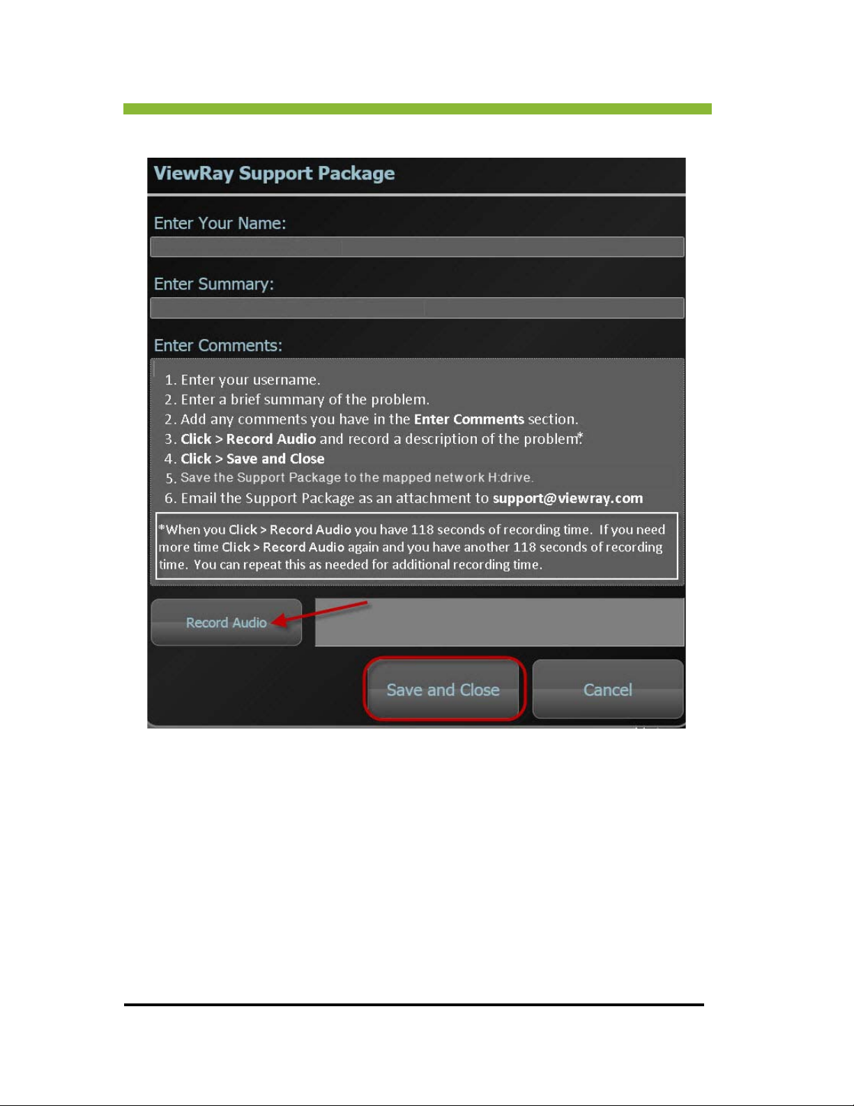
If you encounter a problem using the system you can open a Support Package to log the
problem and report it to ViewRay Service.
ViewRay Inc. MRIdian® system L-0009 Release 4.5 5
Page 24
Chapter 1: MRIdian® System Overview
Press > Ctrl + Alt + F9 and the ViewRay Support Package information box will open.
1.5 System Messages
There are four categories of system messages:
Information
Warning
Error
6 MRIdian® system L-0009 Release 4.5 ViewRay, Inc.
Page 25
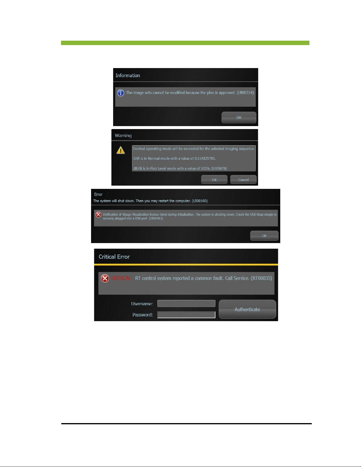
Critical Error
Chapter 1: MRIdian® System Overview
1.6 Uninterruptible Power Supply
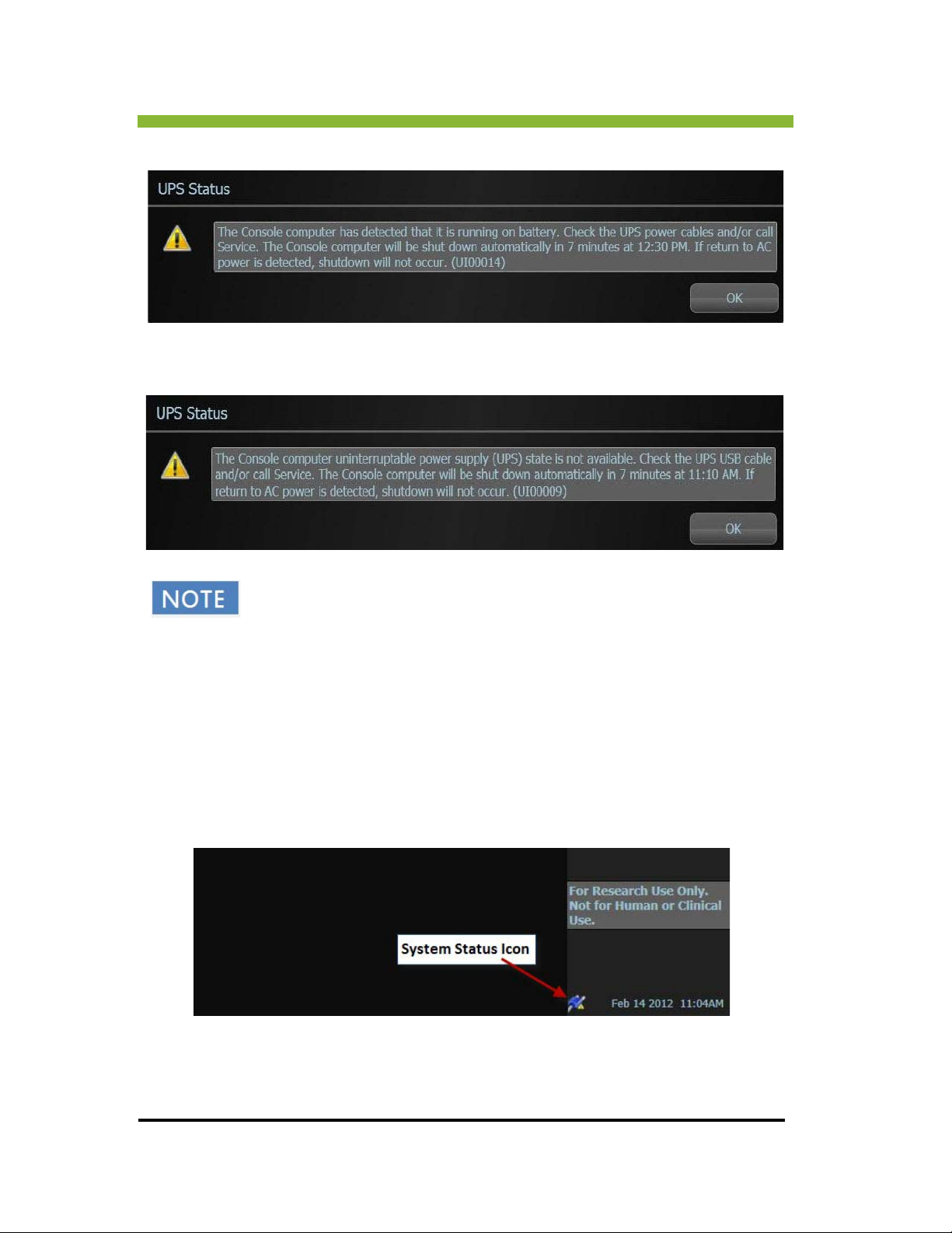
Every console is equipped with an uninterruptible (battery) power supply (Eaton 9PX5KP1). If
power is lost to the main power supply (AC power), the system will run on battery power for
7 minutes and then shut down automatically.
ViewRay Inc. MRIdian® system L-0009 Release 4.5 7
Page 26
Chapter 1: MRIdian® System Overview
As soon as the system detects loss of AC power, the screen will display the following message:
When the system no longer detects the UPS connection, the user will receive the following
warning message:
The system has an auto-save feature that runs in the background on all
planning consoles and saves locally every 2 minutes. There is a similar
eature on treatment delivery consoles. If the system is shut down due to a
f
power outage and loss of UPS battery power, the next time the treatment
delivery system is powered up the system will retrieve the treatment data
and issue a message to the operator that the system has detected and will
retrieve incomplete treatment delivery data.
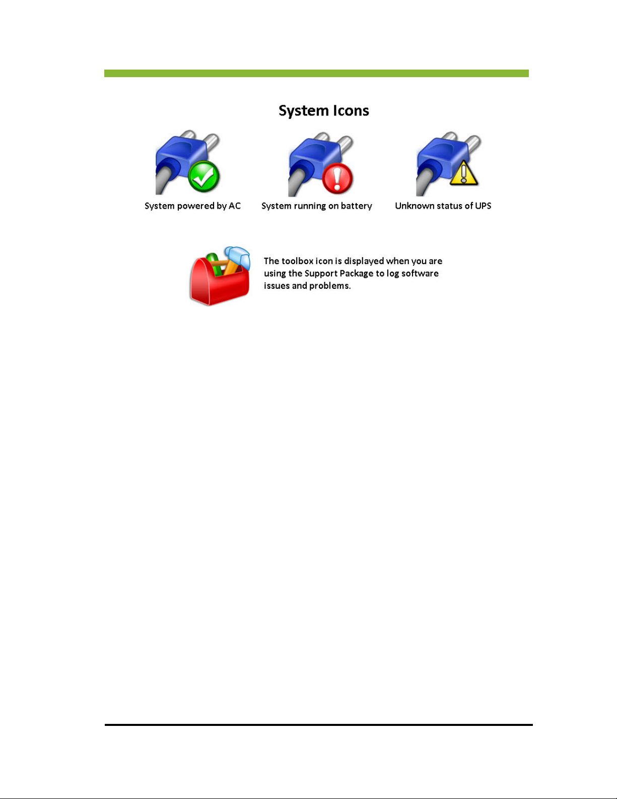
1.7 System Status Icons
The user interface displays icons that represent system status. Those icons are at the bottom,
right of the user interface.
8 MRIdian® system L-0009 Release 4.5 ViewRay, Inc.
Page 27
Chapter 1: MRIdian® System Overview
1.8 Environmental Requirements
Equipment Room: 15°C to 24°C, 40 to 80% Relative Humidity
Treatment Room: 18°C to 22°C, 40 to 60% Relative Humidity
Operator Room: 15°C to 30°C, 40 to 80% Relative Humidity
Electrical: 380/4
Electrical Type: Pr
System Type: B Applied
Coil Type: BF Applie
Mode of Operation: Con
Ingress Protection Rating: IP
80VAC, 50/60 Hz, 150A
otection Against Electrical Shock Class I Equipment
Part
d Part
tinuous
X0
ViewRay Inc. MRIdian® system L-0009 Release 4.5 9
Page 28
Chapter 1: MRIdian® System Overview
1.9 Imaging System
The MRIdian Magnetic Resonance Imaging System (MRIS) is a 0.35T horizontal field MRI. The
superconducting magnet, RF coils, and gradient coil have been engineered by design to allow
operation with the radiotherapy gantry of the MRIdian system.
Three soft-tissue imaging planes can be captured continuously during treatment without
e
xposing the patient to unnecessary ionizing radiation. If the tumor or a critical structure
moves beyond a physician-defined boundary, the treatment beam is automatically paused;
when the structure moves back into the target zone, treatment automatically resumes.
Physicians can set both spatial and time thresholds for pausing treatment delivery, controlling
for the motion of a patient's organs based on real-time 4D MRI data.
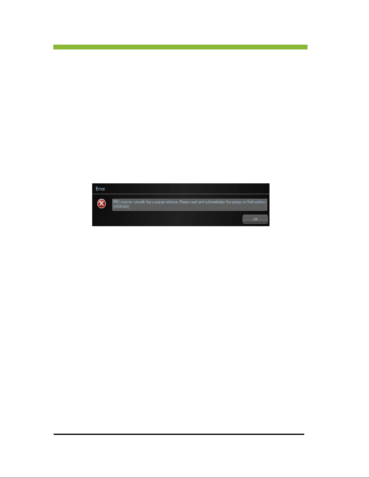
During patient scanning, if there is an imaging error the following popup will be displayed on
the MRIdian
system console
Click > OK and then go to the MRI host console and dismiss the error message. After
dismissing the error message you can return to the MRIdian console and resume imaging. For
further instructions on imaging your patient see “Acquiring Images” on page 310 and “Using
Daily Images to Position the Patient” on page 338.
1.10 Cooling System
Because the magnet is a super-conducting magnet, it is filled with liquid helium as a coolant
to maintain the magnetic field. Following installation, the magnet is adjusted to the desired
operating field strength.
The ramped-up magnet does not require additional ele
field. However, a refrigeration system must be constantly operating to keep the liquid helium
from boiling off.
1.10.1 Magnetic Shielding
To minimize the effects of the magnetic fringe field on the environment, the magnet is
equipped with active super-conducting shielding.
ctric power to maintain the magnetic
10 MRIdian® system L-0009 Release 4.5 ViewRay, Inc.
Page 29
Chapter 1: MRIdian® System Overview
1.10.2 Gradient System
The gradient system is a whole body gradient system. The gradient coils alter the static
magnetic field to specifically focus it on a selected part of the body enabling image “slices”.
The rapid on-and-off switching of the gradient magnets creates the “clanging” noise during
image acquisition.
The gradient system consists of three gradient coils, each oriented on one of the three
oordinates--x,y, and z.
c
During an image acquisition, each of the three gradient coils are switched on and off many
es for spatial encoding and for signal refocusing. The gradient system has a maximum
tim
strength of 18 mT/m and a maximum slew rate 200 T/m/s. The compliance volume of the
gradient system is a cylinder with its axis coinciding with the magnet axis and with a radius of
0.35 m.
1.11 Patient Handling System
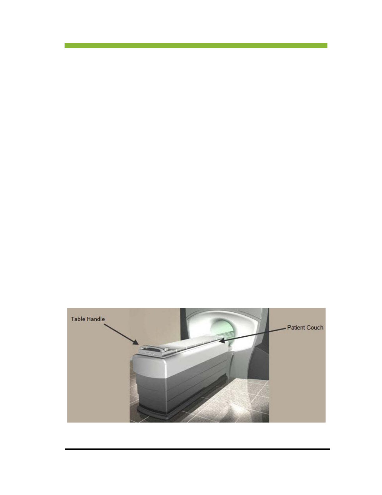
The patient handling system consists of the patient couch/table, and the control panel for the
operator to set up the patient and control the bore environment for patient comfort. The
couch controls allow the operator to lower the table for patient access, and position the
couch longitudinally, vertically and laterally.
The control panels are described in detail in Chapter 8. See “Displays and Indicators” on
page 325.
ViewRay Inc. MRIdian® system L-0009 Release 4.5 11
Page 30

Chapter 1: MRIdian® System Overview
The table top is equipped with indexing notches compatible with available indexing devices
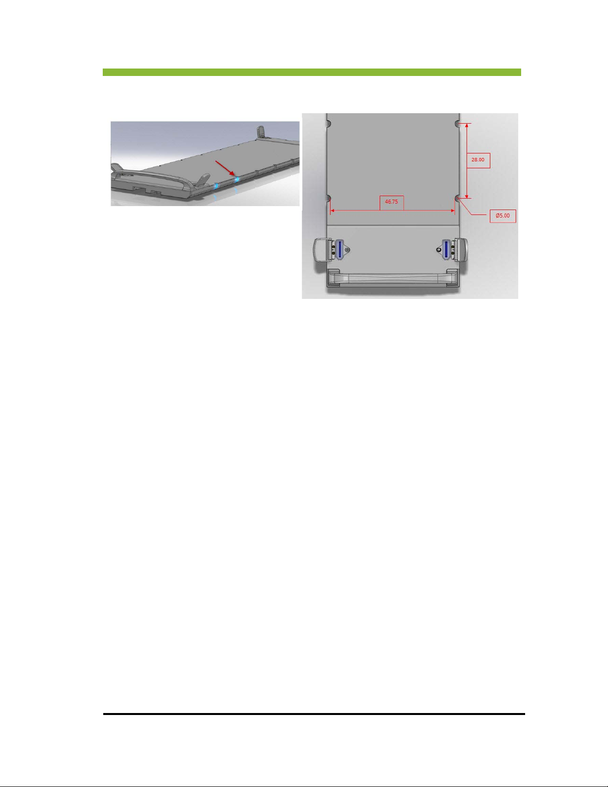
that lock down patient immobilization devices. The notched-style indexing points are 5 cm in
diameter, spaced 28 cm between notch centers, and 46.75 cm across table width from notch
center to notch center.
12 MRIdian® system L-0009 Release 4.5 ViewRay, Inc.
Page 31
Chapter 1: MRIdian® System Overview
Positioning patients’ immobilization devices using the same index notches each time
increases target accuracy.
1.12 Receive Coils
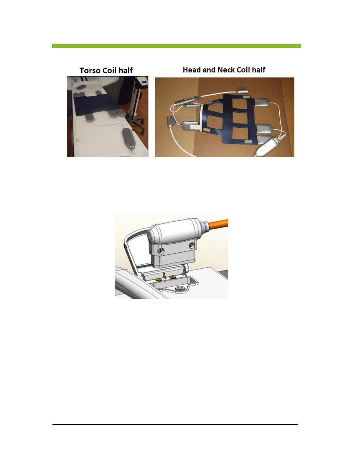
There are two types of receive coils—a torso receive coil and a head and neck receive coil.
The torso receive coils are a two-part, 12-eleme
above and below the patient and plugged into the patient couch. Each half (upper and lower)
of the coil has 6 elements. Each of the 12 coil elements functions as an independent receiver.
The MR image is constructed from the hydrogen nuclei resonance detected by all of the
individual receivers.
The head and neck coils are a two-part 10-element, phase array coil. E
lower) of the coil has 5 elements. For more information on the coils see “Receive Coils” on
page 439.
nt, phase array coil. The coils are placed
ach half (upper and
ViewRay Inc. MRIdian® system L-0009 Release 4.5 13
Page 32
Chapter 1: MRIdian® System Overview
1.12.1 Coil Sockets
There are four coil sockets on the patient couch for attaching the receive coils. One is located
on each corner of the couch.
1.13 Radiation Therapy Delivery System
The MRIdian® Radiation Therapy Delivery System (RDS) consists of a three-headed 60Cobalt
radiation therapy unit mounted on a ring gantry. The radiation isocenter is in the middle of
the magnetic resonance imaging field of view, enabling imaging at the radiotherapy isocenter
before and during therapy.
14 MRIdian® system L-0009 Release 4.5 ViewRay, Inc.
Page 33

Chapter 1: MRIdian® System Overview
1.13.1 Radioactive Source and Shielding
The MRIdian system has three shielding heads—one for each 60Cobalt source. The shielding
heads are made of tungsten and depleted uranium encased in 300 series stainless steel.
Within each head there is a source drawer encased in a shuttle for additional protection.
1.13.2 Multi-leaf Collimator
Each shielding head has a beam-shaping multi-leaf collimator (MLC). Each leaf is doubly
focused so the leaf edges and the leaf ends project to within 1 mm of the source focus point.
The aperture on the source heads restricts the MLC field to a 27.3 cm square field at
radiotherapy isocenter.
1.14 Patient Communication System
The patient communication system consists of:
Patient Headphones
Treatment Room Speakers
Treatment Room Microphones
Flat-Panel Display Monitor
Intercom
Video Camera
Squeeze Bulb
1.14.1 Patient Headphones
The patient headphones plug into the patient couch and can play music and are used to speak
with the patient.
ViewRay Inc. MRIdian® system L-0009 Release 4.5 15
Page 34
Chapter 1: MRIdian® System Overview
1.14.2 Treatment Room Speakers
The treatment room speakers broadcast from the control room to the treatment room.
1.14.3 Treatment Room Microphones
There are two microphones built into the patient handling system. There is also a microphone
located at each end of the magnet.
1.14.4 Flat-Panel Display Monitor
Display monitor inside the control room that streams video from treatment room.
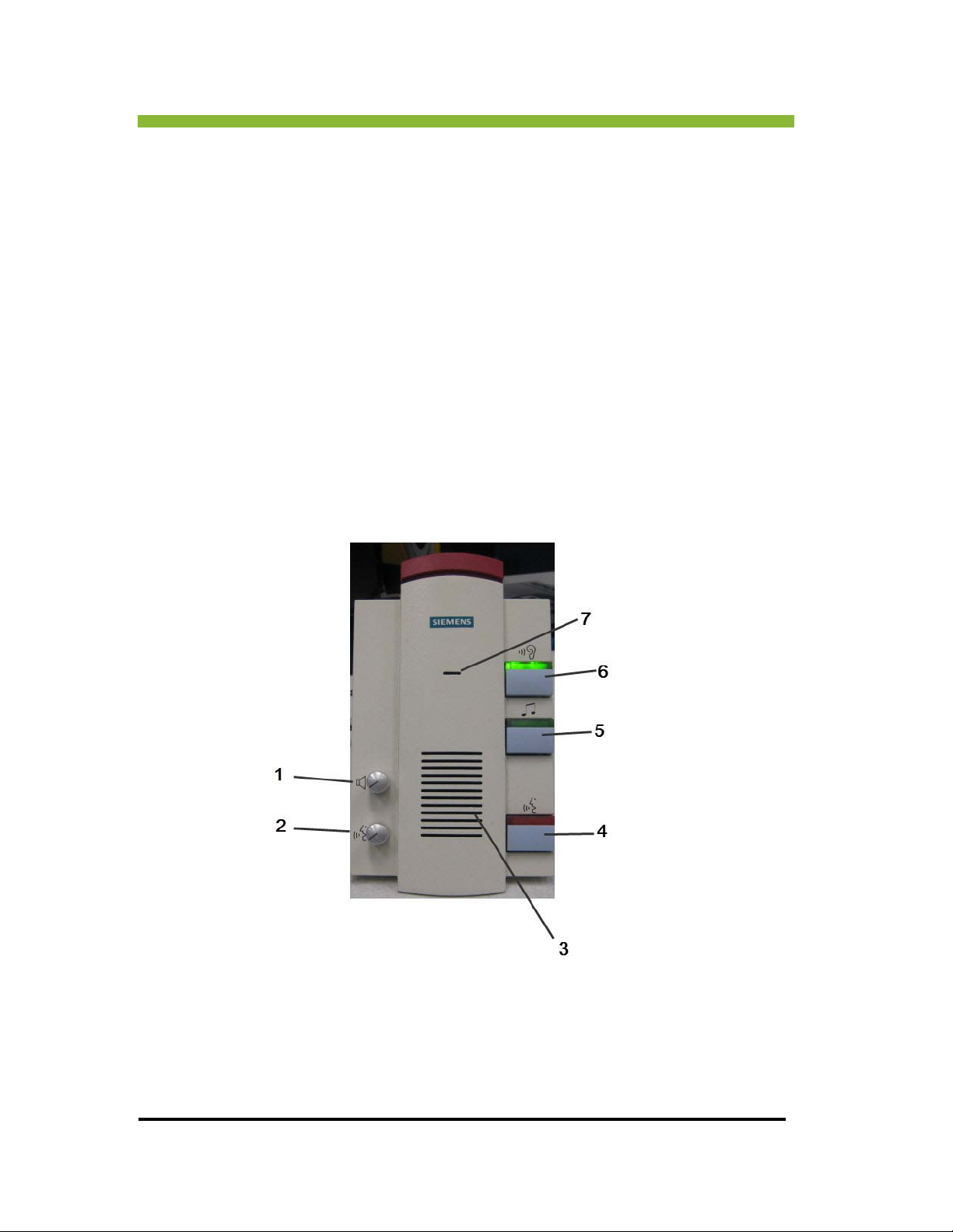
1.14.5 Intercom
The intercom system allows verbal communication between the patient and operator.
1. Listen-mode volume control
2. Broadcast-to-patient volume control
3. Speakers
16 MRIdian® system L-0009 Release 4.5 ViewRay, Inc.
Page 35
Chapter 1: MRIdian® System Overview
4. Speak Button (Hold Down to broadcast to patient)
5. Music on/off
6. Listen (press once to turn on for duration of scan)
7. Microphone
1.14.6 Video Camera
The video camera is installed in the treatment room and used to visually monitor patients
during scanning and treatments.
1.15 Electronics Cabinets
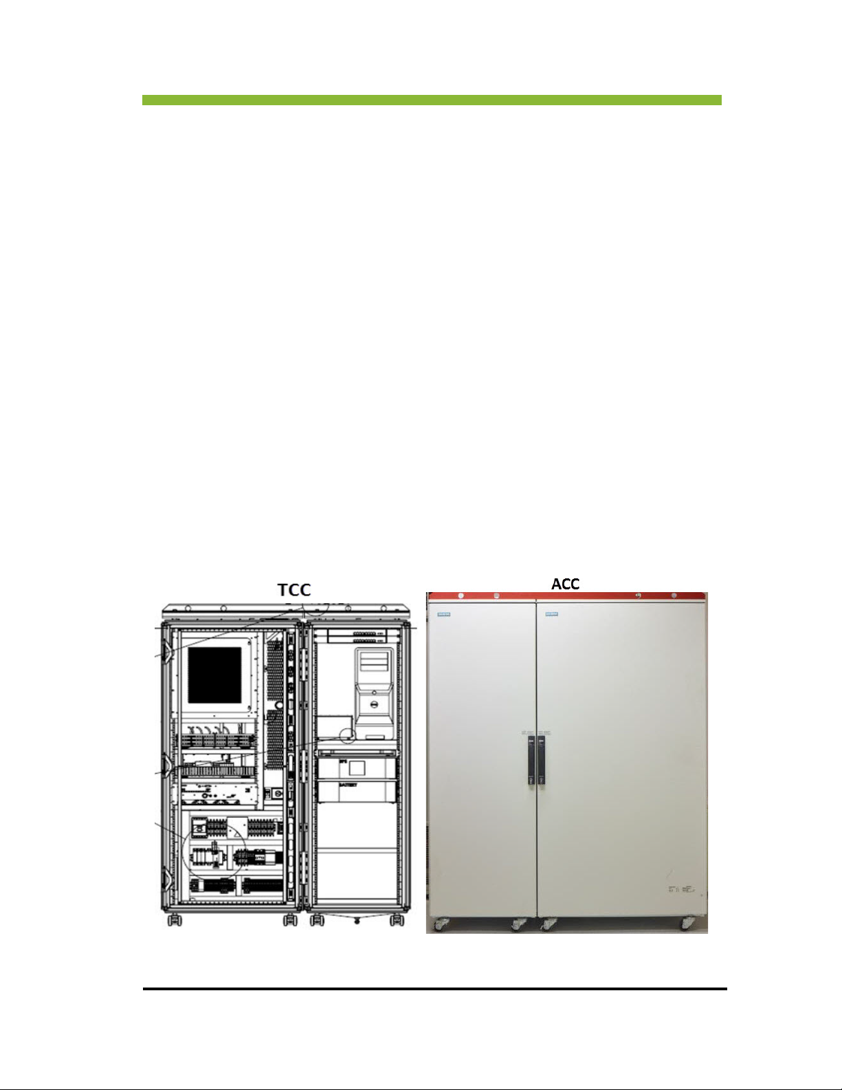
There are two electronics cabinets—The TCC and the ACC. They house the power distribution
transformer, power supplies, computer system and water-to-water heat exchangers.
ViewRay Inc. MRIdian® system L-0009 Release 4.5 17
Page 36

Chapter 1: MRIdian® System Overview
(1) Gradient cabinet
(2) MRI control cabinet
(3) System separator
Once installed, the electronics cabinets are fixed equipment and should
ONLY be moved by ViewRay Service Personnel.
1.16 About this Manual
The manual contains step-by-step instructions for operating the ViewRay System. This
manual includes information on the following topics:
System Overview: Provides general information about the ViewRay System and instructions
in how to use the manual.
Safety Information and Alerts: READ THIS SECTION BEFORE OPERATING THE ViewRay
System. The safety section provides general, patient, operator, MR, radiation, electrical and
18 MRIdian® system L-0009 Release 4.5 ViewRay, Inc.
Page 37

Chapter 1: MRIdian® System Overview
fire safety, interlock explanations, location of emergency stop buttons and contains
procedures for magnet quench, and patient emergency during treatment or scanning,
System Coordinates: Explains the MRIdian system three-dimensional coordinate system
and has direction definitions.
Start-Up and Administrative Tasks: Contains start-up and shut-down instructions for the
planning and delivery consoles and all administrative tasks.
Treatment Planning: Provides instructions for creating a treatment plan, importing data
from DICOM, adding and fusing images, optimizing the dose prescription, setting RealTarget
parameters.
Imaging: Instructions for importing and exporting images, using the magnetic resonance
imaging system (MRIS) for patient image management, patient imaging and for simulating a
treatment delivery.
Patient Set-Up: Includes an overview of all the components of the patient handling system
and instructions for positioning your patients.
Prescription and Patient Management: Provides instructions for the basic tasks of
registering a patient, viewing, approving, disapproving, and exporting patient data, patient
positioning, imaging, setting up rapid treatment, and procedures for fault modes.
Treatment Delivery: Provides instructions for delivering a treatment plan and for using on-
table treatment planning which includes contouring, dose prediction, re-optimization, plan
approval, and delivery of radiation treatment.
Quality Assurance: Contains step-by-step instructions for the MRIdian system quality
assurance procedures and recommended frequencies for all QA procedures.
Cleaning: Instructions for cleaning the equipment
Receive Coils: Detailed information about coil use, placement, precautions, cleaning, and
service.
ViewRay Inc. MRIdian® system L-0009 Release 4.5 19
Page 38

Chapter 1: MRIdian® System Overview
TABLE 1. Instruction conventions used in this manual
Numbered lists
1.
2.
3.
Arrow >
Are action steps
Indicates an action sequence,
for example:
Click > Plan
Bold
Indicates the result of an action step
Screens and button names, dialog
boxes, menu items, and user actions
are all set in bold
20 MRIdian® system L-0009 Release 4.5 ViewRay, Inc.
Page 39

Chapter 2: Safety Information and
Chapter 2: Safety Information and Alerts
2.1 Safety Introduction
The MRIdian® system has specific safety requirements in the following areas:
A strong magnetic field is always present in the treatment room requiring special
non-ferrous (non-magnetic) equipment and screening of individuals prior to entry to
this environment. See “Imaging Safety” on page 34.
The patient handling system requires careful use by the operator to prevent injury
from pinch points or collision with the system bore. See “Treatment Room Safety” on
page 31.
Noise from the MRIdian® MRIS during imaging may be hazardous and should be
reduced through the use of hearing protection. See “Hazardous Noise Levels” on
page 50.
Radioactive sealed sources that contain
treatment. Possession of these sources requires compliance with a Radiation Safety
Program and exposure monitoring. See “Radiation Precautions” on page 58.
60
Co are used for the radiotherapy
Positioning lasers may pose a hazard to the eyes of the operator and patient if the
laser beam is aimed directly at the eyes. See “Laser Positioning Safety” on page 33.
The MRIdian system is not suitable for use in the presence of flammable mixtures or
materials. Ensure there are NO flammable mixtures or materials in the treatment
room where cryogens are located.
Keeping yourself and your patients safe is always the top priority. As a healthcare worker you
a
n increase safety by knowing your work environment and the answers to these safety
c
questions:
• What adverse things can happen?
• What are the consequences?
How do I prevent adverse and potentially harmful situations from happening?
•
•
How should I respond to an emergency situation?
ViewRay Inc. MRIdian® system L-0009 Release 4.5 21
Page 40
Chapter 2: Safety Information and Alerts
This safety chapter is designed to answer those questions as they pertain to using the
MRIdian system. The chapter is organized into the following sections: General Safety, MR
Safety, Radiation Safety, Electrical Safety, Treatment Room Safety and Emergency Procedures.
To ensure your safety and the safety of your patients, it is very important that you read this
chapter and familiarize yourself with the system and its safety requirements and precautions.
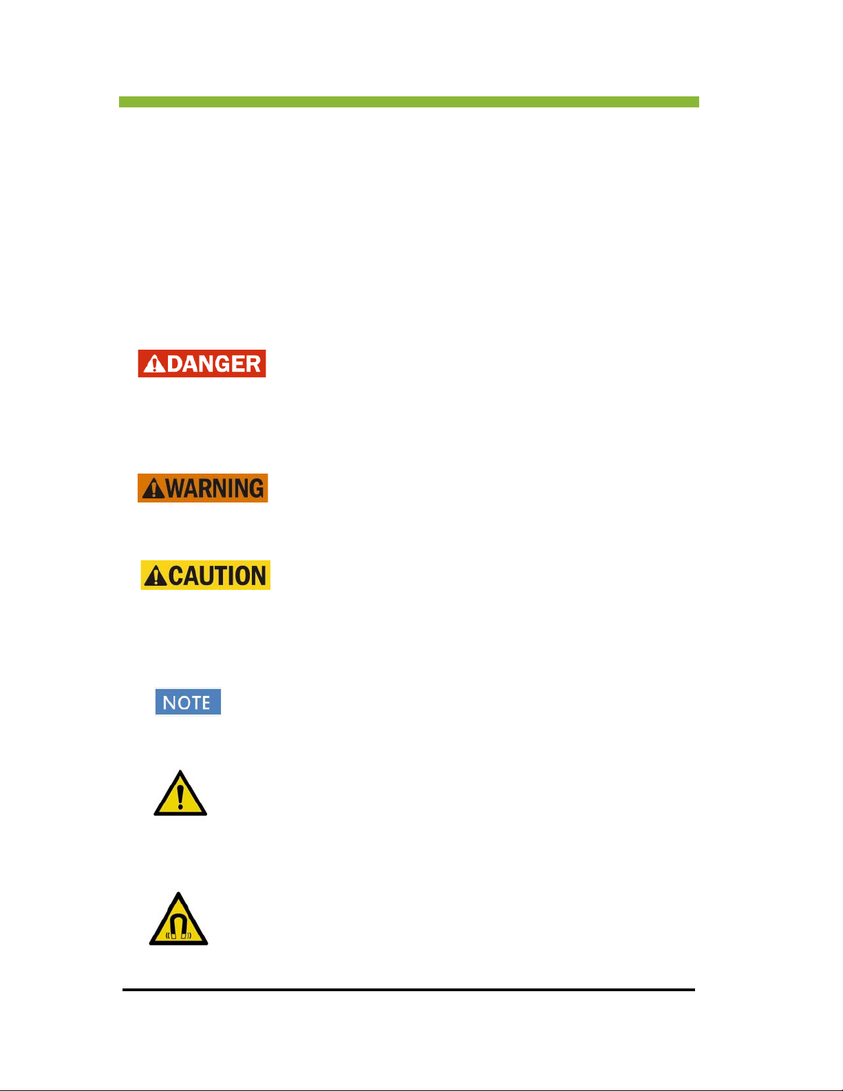
2.1.1 Definition of Hazard Levels and Symbols
Danger indicates a major hazard situation which presents a highly
probable threat of serious injury or death.
system.
Warning indicates a potentially hazardous situation, which, if not
avoided, has the potential to result in serious injury or death.
Caution indicates a potentially hazardous situation which may
result in minor to moderate injury.
NOTE indicates an important reminder or message not related to personal
injury.
General warning. Indicates an important consideration when using the
Indicates a magnetic field alert.
22 MRIdian® system L-0009 Release 4.5 ViewRay Inc.
Page 41
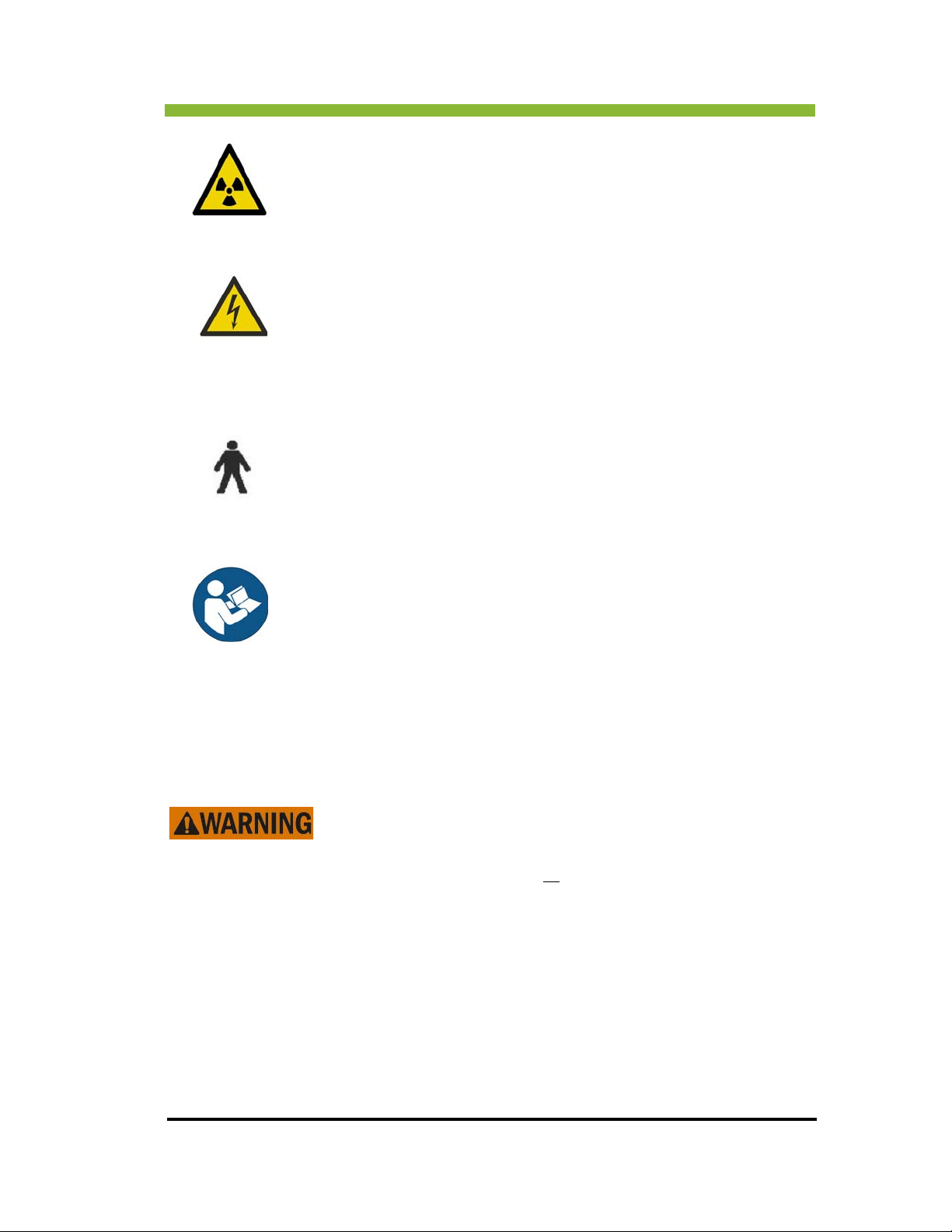
Chapter 2: Safety Information and
Indicates a radiation alert.
Indicates an electricity alert.
Indicates a Type B applied part and that leakage is in compliance with
IEC60601-1
This symbol means FOLLOW OPERATING INSTRUCTIONS.
2.1.2 General MRIdian® System Safety
The MRIdian system is a radiation therapy device with an
integrated magnetic resonance (MR) system for imaging. Improper
use of the MRIdian system can result in serious injury or death. Be
sure to read and understand
It is the responsibility of the Radiation Oncology site to ensure that applicable
national, state and local requirements, regulations, and ordinances affecting the
MRIdian® System equipment and its radionuclide are met. Specific questions about
regulatory requirements should be directed to your Authority Having Jurisdiction,
the site Physicist of Record, and the Radiation Safety Officer.
When operating the MRIdian system always follow the procedures and monitoring
requirements established by your facility’s Radiation Safety Officer.
all the safety information.
ViewRay Inc. MRIdian® system L-0009 Release 4.5 23
Page 42

Chapter 2: Safety Information and Alerts
When operating the MRIdian system always obey all DANGER, WARNING and
CAUTION statements that are given with the procedures in this manual.
Follow your facility's Universal Precautions practices to prevent infection and cross-
contamination.
Ensure that all MR workers and patients have Magnetic Resonance Safety Training
and Screening and that it includes (Electromagnetic Field) EMF safety precautions
BEFORE entering the treatment room. It is generally accepted that no published
evidence exists supporting cumulative or long-term EMF effects from MR exposure.
The possible physiological effects of exposure to a static magnetic field are dizziness,
vertigo, and a metallic taste in the mouth. Patient or MR worker exposure to the
static magnetic field can be minimized by staying away from the magnet and
avoiding rapid movements of the head while in the static magnetic field.
Extra precaution is advised for pregnant MR workers. Local regulations may apply.
State limits for MR workers may not apply when an MR worker is pregnant.
MR workers and janitorial staff for MR suite must not have electronic or metallic
implants or piercings. MR workers must be screened for previous occupational activities which may have caused accidental lodging of ferromagnetic materials, such as
dded metal fragments from military or work activities.
embe
The facility must develop and use an MR Screening Form to identify any conditions,
due to professional activity, past medical history, present medical state, or otherwise, that would prohibit an MR worker or patient from safely entering the MR environment of the treatment room. ALL individuals must complete the screening
BEFORE entering the MR environment.
Follow all applicable national and local requirements and regulations regarding
material and equipment decommissioning and disposal.
2.2 Product Performance Liability
If the MRIdian ®System is not used in accordance with the operator’s manual,
ViewRay accepts no responsibility for the safety, reliability and performance
system. The performance of this device was tested on the finished
of the
device. The device was made according to established procedures and
industry standards, such as IEC 60601-1, 60601-1-2, 60601-2-11, 60601-2-33.
Unauthorized modifications made to this device can void the warranties and
may create the potential for hazards for which ViewRay cannot accept
responsibility. Connect ONLY items that are specified as part of the ME
equipment.
24 MRIdian® system L-0009 Release 4.5 ViewRay Inc.
Page 43

Chapter 2: Safety Information and
2.2.1 Electrical Safety
To avoid the risk of electric shock, the system must be connected to a supply mains with
protective earth.
2.3 Guidance and Declaration for Electromagnetic Compatibility
2.3.1 Precautions
To maintain the safety of the system, ensure all installation
and connections to the MRIdian system are performed by
ViewRay or ViewRay authorized pe
Electrical wires and cables should be inspected periodically to
ensur
e the insulation has not been damaged, all connections
are secure, and there are no indications of damage.
rsonnel.
To maintain electrical safety, the operator’s station must be
correctly connected to all peripherals.
All peripheral equipment not specified for use in the CONTROLLED ACCESS AREA, may be
functi
onally disrupted by electromagnetic interference of the MR equipment, and conversely,
the peripheral equipment may disrupt the functioning of the MR equipment.
Only equipment marked MR-Safe by its manufacturer should be used in the treatment room
Do not take any electronic devices into the
equipment room, such as cell phones, pagers, or radio-frequency ID devices.
treatment room, operator's console, or
2.3.2 Electromagnetic Compatibility
The MRIdian® system was tested for radiated emissions and immunity and complies with the
requirements of IEC 60601-1-2. All testing was performed outside of the “controlled access
area”. However, the components inside of the RF-shielded room were connected and they
were fully operational when the EMC testing was performed; therefore, the test results
ViewRay Inc. MRIdian® system L-0009 Release 4.5 25
Page 44

Chapter 2: Safety Information and Alerts
tested for radiated RF immunity
at the follo wing frequencies:
GHz.
Amplifier 9 K Hz to 2080 MHz for 80MHz
GHz u sed to test 2. 4 GHz
represent the entire system and not only those components of the system that are outside of
the RF-shielded room. The test results are only valid with the standard system cabling that is
also the prerequisite for the complete functionality of the system (also including all
components inside the RF-shielded room).
Medical electrical equipment needs special precautions regarding EMC and needs to be
ins
talled and put into service according to the EMC information provided in the
accompanying documents.
Electromagnetic compatibility is the ability of equipment or a system to function satisfactorily
in its
electromagnetic environment without introducing intolerable electromagnetic
disturbance to anything in that environment.
Portable and mobile RF communications equipment can affect medical electrical equipment.
The MRIdian is classified as a large and permanently installed
equipment per IEC 60601-1-2. The exemption according to the
equirement 36.202.3b) 9 of this standard has been used and the
r
equipment was not tested for radiated RF immunity over the entire
frequency range of 80 MHz to 2.5 GHz.
The ViewRay system has been
Modulation characteristic: si nusoidal 1 KHz, 80% AM
Test Level: 3V/m
Signal generators with amplifier: R&S Logperiodic Antenna with IFI Power
Fixed equipment or system cabling, which cannot be removed by the user, is
not listed. This cabling is part of the system and was regarded at all EMC-
80 MHz through 1000 MHz, 1.2 GHz and 2.4
through 1000 MHz
Kenwoo d Licensed t ransmitter range 1.2-1.3
GHz u sed to test 1. 2 GHz
Linksys licensed tran smitter ran ge 2.40-2.48
26 MRIdian® system L-0009 Release 4.5 ViewRay Inc.
Page 45

Chapter 2: Safety Information and
considerations. Without this cabling there is no complete functionality of the system.
The use of accessories, transducers and cables other than those
specified, with the exception of transducers and cables sold by the
manuf
acturer of the equipment or system as replacement parts
for internal components, may result in increased emission or
decreased immunity of the equipment or system.
Guidance and Manufacturer's Declaration- Electromagnetic Emissions
The MRIdian® system is intended for use in the
electromagnetic environment specified in the
following tables. The customer or the user of the MRIdian system should ensure that it is
used in such an environment.
IEC60601-1-2 Table 1 Guidance and Manufacturer’s Declaration—Electromagnetic Emissions
Emissions test Compliance Electromagnetic environment – guidance
Line Conducted Emissions
CISPR 11
Class A;
2.6dB below
the
limits
The MRIdian system must emit
electromagnetic energy in order to perform
its intended function. Nearby electronic
equipment may be affected.
Radiated RF Emissions
CISPR 11
Class
A;1.0dB
below the
limi
ts
The MRIdian system must be used only in a
shielded location with a minimum RF
shielding effectiveness. For each
cable that
exits the shielded location, a minimum filter
attenuation of 80dB from 10-20MHz, 100dB
from 20-80MHZ and 80dB from 80-100MHz
Harmonic Emissions
IEC 61000-3-2
N/A
Standard applies to equipment rated < 16
Amps,
for the MRIdian system this is the
treatment delivery and planning console
only.
Voltage Fluctuations and
Flicker
IEC 61000-3-3
N/A Standard applies to equipment rated < 16
Amps,
for the MRIdian system this is the
treatment delivery and planning console
only.
It is essential that the actual shielding effectiveness and filter attenuation be
verified at the location.
ViewRay Inc. MRIdian® system L-0009 Release 4.5 27
Page 46

Chapter 2: Safety Information and Alerts
The MRIdian system should ONLY be used with manufacturer-labeled MR-Safe
equipment. MR-Safe equipment has no significant influence on the quality of
imag
e information from the MR system. Furthermore, the characteristics of
the MR-Safe equipment are not affected by the MR system.
Guidance and Manufacturer’s Declaration of Electromagnetic Immunity
IEC60601-1-2 Table 2 Guidance and Manufacturer's Declaration—Electromagnetic Immunity
Immunity test IEC 60601 Test
Level
ImmunityElectrosta
tic
±6 kV contact
±8 kV air
Discharge (ESD)
IEC 61000-4-2
Electrical Fast
Transients and
rsts
Bu
IEC 61000-4-4
Surges
IEC 61000-4-5
±2 kV for power
supply lines
±1 kV for signal
nes > 3m
li
±1 kV differential
mode
±2 kV common
de
mo
Voltage Dips
and Short
Interruptions
IEC 61000-4-11
0% V
cycle
40% V
70% V
Nom
Nom
Nom
- 0.5
-5 cycle
-25
cycle
0% V
Nom -
5 sec.
Compliance Level Electromagnetic environment –
gu
idance
±6 kV contact
±8 kV air
Floors should be wood, concrete
or ceramic
tile. If floors are
covered with synthetic material,
the relative
humidity should be at least
30 %.
±2 kV for power
supply lines
±1 kV for signal
es
lin
±1 kV differential
mode
±2 kV common
Mains power quality should be
that of a typical commercial or
hospital environment.
Mains power quality should be
that of a typical commercial or
hospital environment.
mode
0% V
40% V
70% V
0% V
-0.5 cycle
Nom
Nom
Nom
– 5 sec.
Nom
-5 cycle
-25 cycle
Standard applies to equipment
rated <
16 Amps, for the MRIdian
system this is the treatment
delivery and planning console
only. As delivered with the
MRIdian system, both consoles
are connected to an
uninterruptible power supply.
Power
requency (50/
F
60 Hz) magnetic
field IEC 610004-8
3 A/m 3A/m Power frequency magnetic fields
ould be at levels characteristic
sh
of a typical location in a typical
commercial or hospital
environment.
28 MRIdian® system L-0009 Release 4.5 ViewRay Inc.
Page 47
Chapter 2: Safety Information and
IEC60601-1-2 Tables 4, 8- Electromagnet
Immunity test IEC 60601 Test
Level
Conducted
isturbances,
D
Induced by RF
Fields
IEC 61000-4-6
Radiated RF
Electroma
Fields
IEC 61000-4-3
gnetic
3 V RMS
0.15 MHz to
80 MHz
3V/m
80MHz to
2.5 GHz
Compliance
Level
3 V RMS N/
3V/m 80 MHz to 1000 MHz:
ic Immunity
Electromagnetic environment – guidance
d = 1.0 √P
1.2GHz to 2.4 GHz:
d = 0.1√P
where P is the maximum output power rating of
the transmit
according to the transmitter manufacturer and
d is
distance in meters (m). Fi
fixed RF transmitters, as determined
by an electromagnetic site survey,
less than the compliance level in
each frequency range. Inte
the vicinity of equipment marked
with the following symbol:
A
ter in watts (W)*
the recommended separation
eld strengths from
should be
rference may occur in
Note 1: At 80 MHz and 1000 MHz, the higher frequency range applies.
Note 2: These guidelines may not apply in all si
tuations. Electromagnetic propagation is
affected by absorption and reflection from structures, objects and people.
Note 3: It is essential that the actual shielding effectiveness and filter attenuation of the
shielded loc
ation be verified to ensure that they meet the minimum specification.
* Field strengths from fixed transmitters, such as base stations for radio (cellular/cordless)
telephones and land mobile radios, amateur radio, AM and FM radio broadcast and TV
broadcast cannot be predicted theoretically with accuracy. To assess the electromagnetic
environment due to fixed RF transmitters, an electromagnetic site survey should be
considered. If the measured field strength outside the shielded location in which the
MRIdian system is used exceeds [field strength] V/m, the MRIdian system should be
observed to verify normal operation. If abnormal performance is observed, additional
measures may be necessary, such as relocating the MRIdian system or using a shielded
location with a higher RF shielding effectiveness and filter attenuation.
ViewRay Inc. MRIdian® system L-0009 Release 4.5 29
Page 48
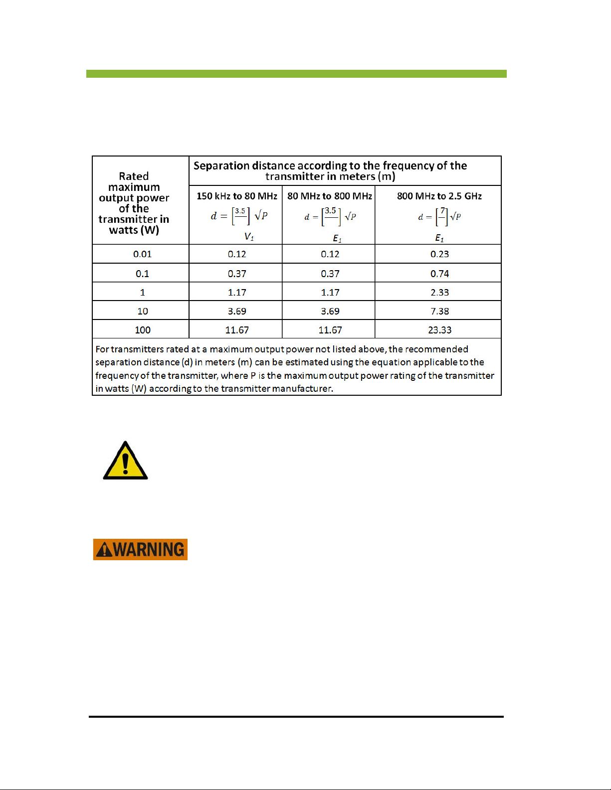
Chapter 2: Safety Information and Alerts
Recommended Separate Distances between Portable and Mobile RF
Communications Equipment and the MRIdian system.
IEC60601-1-2 Table 6
The MRIdian system equipment should not be moved from its installation
position, or stacked, because testing was conducted with the system in
the installation position.
2.1 Proper Patient Identification
Selection of the incorrect treatment plan over a number of treatment
fractions can result in serious injury to the patient.
Before entering a patient into the system, make sure each patient is
eened for MR safety. See “MR Safety Screening” on page 35.
scr
Verify that the patient photo and patient information correctly
identifies the patient you are about to treat.
Make sure you select the correct patient plan and procedure for
the patient.
30 MRIdian® system L-0009 Release 4.5 ViewRay Inc.
Page 49

Chapter 2: Safety Information and
2.4 Treatment Room Safety
2.4.1 Slipping and Falling Hazards
Clean up all spills from the floor and the patient table before allowing
another patient to enter the treatment room. Make sure the floor is
c
ompletely dry before admitting another patient to the treatment
room.
Follow your facility’s Infections Control and Universal Precautions.
Make sure all cables and hoses are routed out of all pathways in the treatment room so they
will not
cause a patient or healthcare worker to trip and fall.
2.4.2 Pinch Points
Pinch points created by manual and automatic movement of the
patient couch may cause serious injury.
Before and during movement of the patient couch ensure the operator’s and patient’s hands,
ers, toes, linens, clothing, catheters, etc., stay clear of all moving parts, especially
fing
between tabletop and tunnel aperture (bore).
Ensure that patients keep their arms and hands close to their bodies to avoid a pinch point
een the table beam (surface the couch rolls on) and patient couch.
betw
Also see "Fire Safety in the Treatment Room” on page 56.
ViewRay Inc. MRIdian® system L-0009 Release 4.5 31
Page 50

Chapter 2: Safety Information and Alerts
2.5 Patient Transport Safety and Communication
2.5.1 Patient Transport System Safety
Collisions and injuries can occur when using the patient table. Observe all warning and safety
signs on the MRIdian system.
Follow these precautions:
Explain all the expected table movements to patients.
Ensure that there are no persons or objects which could collide with the
movement of the patient table top.
Ensure that the patient’s hair, hands, fingers, toes, linens, catheters, and
clothing do not hang off the patient table.
Make sure that IV tubes and MR coils do not hang over and that IV needles
remain in the patient during table movement.
In case of hazardous conditions, press the E-Stop button to stop couch
movement.
Monitor the patient visually and listen with the Intercom system for any sign
of patient distress.
2.5.2 Patient Alert for Patient-Initiated Communication
Patients may use the patient alert to initiate a visual or auditory alert. The visual alert
is an LED display on the intercom. The auditory alert is a activated by a squeeze bulb.
There are two types of auditory alerts:
A continuous tone over the intercom
A brief feedback signal via the patient’s headset and wall speaker
32 MRIdian® system L-0009 Release 4.5 ViewRay Inc.
Page 51

Chapter 2: Safety Information and
2.5.3 Communicating with the Patient
All patients should be monitored during treatment. An Intercom system is supplied for
monitoring and communicating with patients. For an illustration of the intercom with parts
labeled see "Patient Communication System” on page 15. (A video monit
To listen to the patient:
1. Press > Listen button
The Listen LED lights up and the intercom is in the Listen mode. Sounds from
the treatment room are transmitted to the control room.
2. Press > Listen button again.
The Listen LED light goes out and the Listen mode is disabled.
To speak to the patient:
1. Press and hold the Speak button.
or is also provided.)
The intercom is in the Speak mode as long as you hold down the Speak button.
2.6 Laser Positioning Safety
To ensure your lasers are properly aligned, follow the laser alignment protocol
"Daily Laser Alignment Calibration Test” on page 425
Even momentary eye exposure from a laser pointer can cause discomfort and
emporary visual impairment.
t
Never point a laser directly at anyone’s eyes.
Never look directly at a laser.
Never view a laser beam using an optical instrument.
Do not point a laser at mirror-like su
dangerous to the eyes as a direct beam.
rfaces. A reflected beam can be as
ViewRay Inc. MRIdian® system L-0009 Release 4.5 33
Page 52
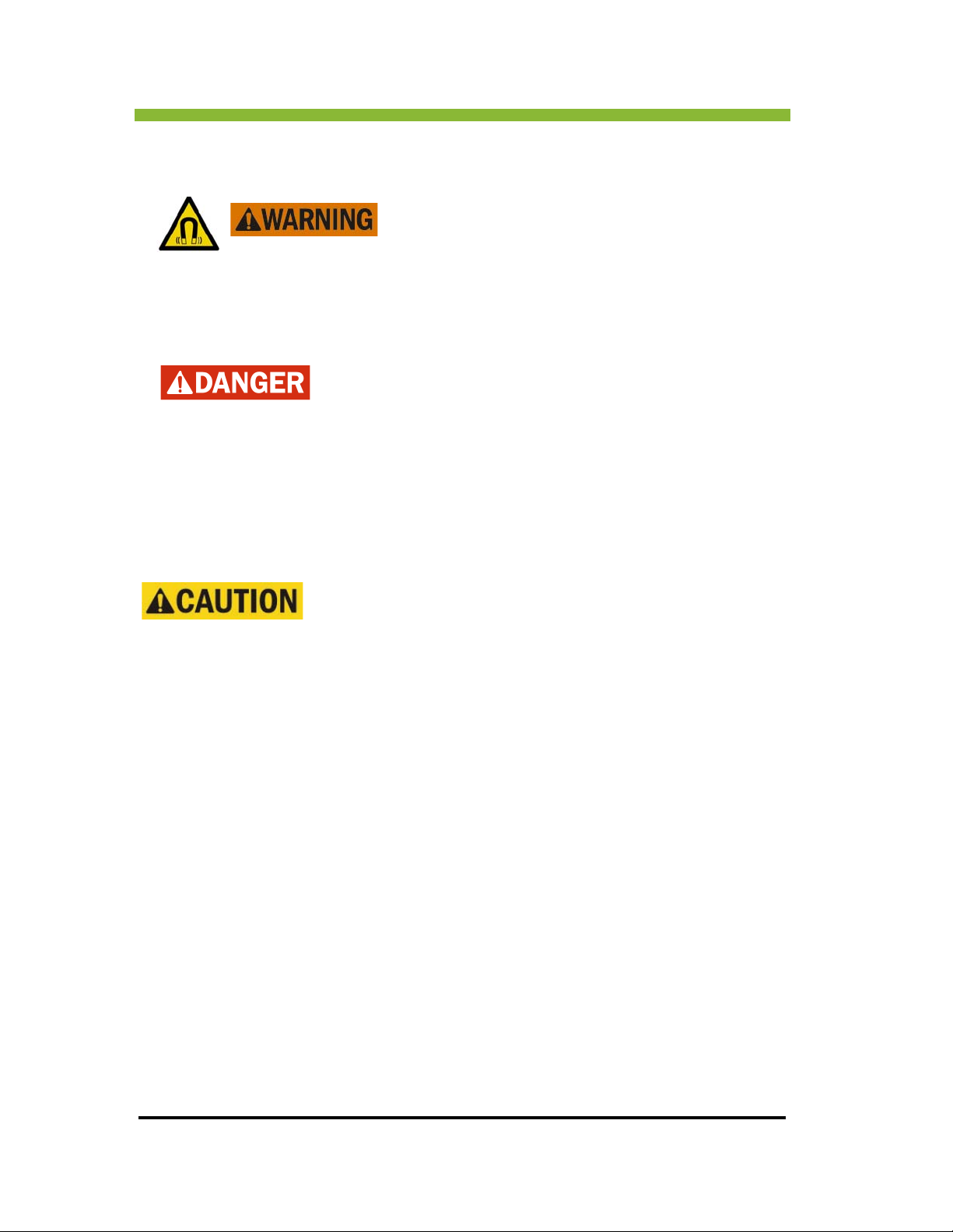
Chapter 2: Safety Information and Alerts
2.7 Imaging Safety
Once energized the magnet is ALWAYS on even when no
imaging is taking place.
The super-conducting magnet generates a strong homogeneous magnetic field with a field
s
trength of 0.35T
Magnetizable objects introduced into the magnetic field
become projectiles and can cause serious injury or death.
anted magnetizable objects can move inside the patient
Impl
and cause serious injury or death.
Life-support devices and emergency care equipment not specified or recommended for use
in the
magnetic field may be disturbed and this equipment may in turn also disturb the
proper functioning of the MR equipment.
The MRIdian® system is only to be used with MR-Safe equipment
as defined in ASTM F2503-08* and labeled as such by the
equipmen
MR Safe
environments. MR Safe items include nonconducting, nonmagnetic items such as a plastic
Petri dish. An item may be determined to be MR Safe by providing a scientifically based
rationale rather than test data.
MR Conditional is
in a specified MRI environment with specified conditions of use. Field conditions that define
the MRI environment include static magnetic field strength, spatial gradient, dB/dt (time
varying magnetic fields), radio frequency (RF) fields, and specific absorption rate (SAR)
MR Unsafe ar
is defined in ASTM F2503-08 as an item that poses no known hazards in all MR
defined as an item that has been demonstrated to pose no known hazards
e items that are known to pose hazards in all MRI environments.
t manufacturer.
34 MRIdian® system L-0009 Release 4.5 ViewRay Inc.
Page 53

Chapter 2: Safety Information and
2.7.1 MR Safety Screening
The facility must develop and use an MR Screening Form to ensure all
electrically conducting objects are removed and to identify any conditions, due
o professional activity, past medical history, present medical state, or
t
otherwise, that would prohibit a person from safely entering the MR
environment of the treatment room. ALL individuals must complete the
screening BEFORE entering the MR environment. "Pre-screening Prior to
Imaging or Treatment on the MRIdian® System” on page 37.
2.7.2 Magnetic Field Emergency Procedures
Before working with the MRIdian® system familiarize yourself with the
location and function of ALL the emergency switches.
difference between the E-Stop button, which stops table movements
and move
Emergency Discharge Button, which is ONLY used in the event that
someone is trapped inside the bore of the magnet by a metal object.
See “Emergency Response Plans” on page 60 and "Using the E-Stop in
an Emergency” on page 62.
s the sources in emergency situations, and the Magnet
2.7.3 Devices Contraindicated for MRI
Even devices labeled MRI-Safe might be capable of causing
injury if the manufacturers instructions for positioning
electrically conducting leads are not followed.
Do not use resuscitation devices such as defibrillators or oxygen bottles which
are not MR-safe in the treatment room.
Do not use transport trolleys, moveable beds, stretchers or other transport
devices that consist of magnetizable parts. All such equipment has to be
marked MR-Safe by its manufacturer.
Do not take any electronic devices into the treatment room, operator’s console,
or equipment room, such as cell phones, pagers, or radio-frequency ID devices.
Know the
Do not wear or carry any magnetizable objects, for example, watches, pens,
scissors, clipboards, tag clips, credit cards, etc., into the treatment room.
ViewRay Inc. MRIdian® system L-0009 Release 4.5 35
Page 54

Chapter 2: Safety Information and Alerts
All peripheral equipment not specified for use in the
CONTROLLED ACCESS AREA, may be functionally disrupted
y electromagnetic interference of the MR equipment, and
b
conversely, the peripheral equipment may disrupt the
functioning of the MR equipment. Only equipment marked
MR-Safe by its manufacturer should be used in the
treatment room
ALWAYS FOLLOW THESE PRECAUTIONS
Only authorized persons should enter the treatment area.
Use only MR-safe devices in the treatment room, operator’s console, or
equipment room, and strictly follow manufacturer’s instructions with
respect to electrically conducting lead positioning or the devices may cause
injury.
Every person who will enter the treatment room, operator’s console, or equipment room
must be trained in MR safety procedures and screened for compatibility, including
emergency responders. (See “MR Safety Screening” on page 35.)
Ensure the janitorial staff is fully trained in MR safety and they use only non-ferromagnetic
cleaning devices.
Service work on the system must be performed by ViewRay personnel or ViewRay
authorized designees only.
2.7.4 Patients Typically Contraindicated for MRI
Do not allow anyone to enter the treatment room before
MR training and pre-screening is completed.
Do not image or allow in the treatment room anyone with electronic or metallic implants
such as cardiac pacemakers, ICDs, cochlear implants, stimulators, or insulin pumps, SwanGanz catheters with thermodilution tips, aneurysm clips in the brain, implanted
neurostimulators, artificial anus, transdermal adhesive dressing, metallic spirals for
contraception, metal or other unidentifiable foreign body in the eyes, or shrapnel or other
metal fragment(s) near a vital organ.
36 MRIdian® system L-0009 Release 4.5 ViewRay Inc.
Page 55

Chapter 2: Safety Information and
2.7.5 Pre-screening Prior to Imaging or Treatment on the
MRIdian
1. Patients for whom use of the MRIdian system is contraindicated.
This includes patients who have metallic implants or
activated implants (e.g., cardiac pacemakers) because the magnetic and electromagnetic
fields may produce strong attraction and/or torque to the implant or may interfere with the
operation of these devices. This applies also to patients who rely on electrically, magnetically
or mechanically activated life support systems. Scanning patients with intracranial aneurysm
clips is also contraindicated unless the physician is certain the clip is not magnetically active.
2. Patients having a higher than normal likelihood of needing emergency medical treatment,
endent of the physical environment of the MRIdian system.
indep
In terms of the need for medical supervision, particular
imaging or treatment with the MRIdian system in the following cases: Patients with greater
than normal potential for cardiac arrest, patients who are likely to develop seizures, or
claustrophobic reactions, decompensated cardiac patients, febrile patients, and patients with
impaired ability to perspire, patients who are unconscious, heavily sedated, or confused, and
with whom no reliable communication can be maintained, and examinations which are
carried out at room temperature above 24 degrees C or relative humidity above 60%. See
"Uninterruptible Power Supply” on page 7.
® System
All individuals undergoing imaging or treatment on the MRIdian system must
first be pre-screened in accordance with ACR Guidance Document for Safe MR
actices: 2007. There are 3 classes of patients who either should not undergo
Pr
MR imaging or who must be imaged using particular caution. Those three
classes are:
electrically, magnetically or mechanically
caution is required in performing
3. Patients having a higher than normal likelihood of needing emergency medical treatment
to the elevated values of the applied fields, when the MRIdian® system operates within
due
the First Level Controlled Operating Mode as described in "Operating Modes” on page 46.
This class includes patients with implanted surgical clips (hemostatic clips) or other
erromagnetic material, patients engaged in occupations or activities which may cause
f
accidental lodging of ferromagnetic materials, or who may have imbedded metal fragments
from military activities, neonates and infants (for whom data establishing safety are lacking),
patients with permanent (tattoo) eye-liner or with facial make-up (severe eye irritation has
been reported), patients with compromised thermoregulatory systems (e.g. neonates, low
birth weight infants, certain cancer patients), patients with metallic implants, because they
may cause artifacts in images due to magnetic field distortion, patients with implanted
prosthetic heart valves, and pregnant patients (the safety of magnetic resonance examination
has not been completely established for embryos and fetuses).
ViewRay Inc. MRIdian® system L-0009 Release 4.5 37
Page 56

Chapter 2: Safety Information and Alerts
Carefully monitor any changes in the each patient’s health and any
procedures the patient has undergone that would
re-screening to determine if the patient is a candidate for MR imaging
or would require special monitoring during MR imaging.
require a complete
2.7.6 MR Worker Screening and Reporting Requirements
All MR workers must undergo an MR screening procedure as part of their employment
interview process to ensure their safety in the MR environment.
All MR per
procedure, or surgery they experience or undergo in which a ferromagnetic metallic object
or device may have been introduced within or on them.
sonnel must immediately report to the MR medical director any trauma,
38 MRIdian® system L-0009 Release 4.5 ViewRay Inc.
Page 57
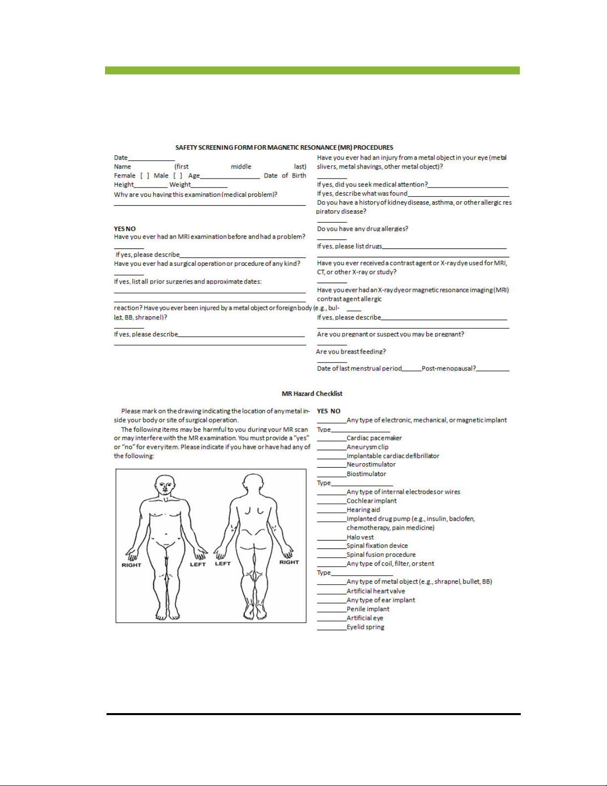
Chapter 2: Safety Information and
2.7.7 Safety Screening Form, MR Hazard Checklist and Patient
Instructions
ViewRay Inc. MRIdian® system L-0009 Release 4.5 39
Page 58

Chapter 2: Safety Information and Alerts
40 MRIdian® system L-0009 Release 4.5 ViewRay Inc.
Page 59

Chapter 2: Safety Information and
2.7.8 Supervision of Patients and Equipment
All patients must receive monitoring during procedures. Monitor the patient visually using
the video camera and also listen using the intercom system for any signs of patient distress.
Ensure medical supervision is provided when the
additional information in "Operating Modes” on page 46.
Continually monitor the system during treatment and procedures and immediately act upon
y system faults or errors.
an
first level mode of operation is used. See
2.8 Artifacts and Imaging Errors
Due to their magnetizability, foreign objects in the area of the magnet bore
cause strong local distortions of the basic field and lead to image artifacts.
oreign objects can also heat up and cause heat injuries to the patient.
F
Depending on the level of distortion, tumor tracking or radiation planning may
be impaired or completely impossible.
Use the following precautions to protect patients from electrical-conducting heat injuries and
o prevent incorrect MR-tracking due to image artifacts:
t
Ensure patients remove all electrically conducting objects such as necklaces,
rings, earrings, piercing, braces, hair bands, etc.
Ensure patients remove all electrically conducting clothing such as bras or belts.
Inform patients that permanent eyeliners and tattoos may contain ingredients
that can cause image artifacts or severe eye and/or skin irritations during MR
imaging and instruct patients to remove all makeup prior to treatment.
ViewRay Inc. MRIdian® system L-0009 Release 4.5 41
Page 60
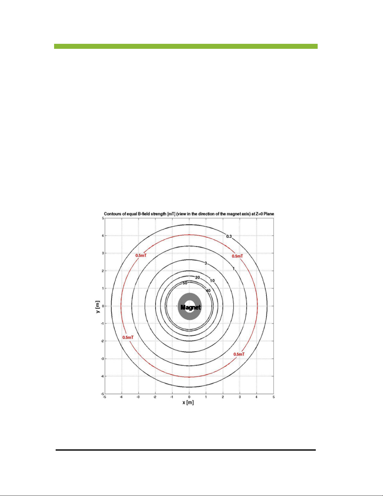
Chapter 2: Safety Information and Alerts
2.9 Controlled Access Area
A magnetic fringe field surrounds the magnet and has an attractive force on metallic objects.
You must clearly mark off, restrict access, and exercise MR safety procedures anywhere the
magnetic field is 5 gauss or higher. See “MR Restricted Access Sign” on page 44. It is the
responsibility of the facility to follow any local statutory requirements with respect to access
o the controlled area.
t
2.9.1 Fringe Field Effects on Devices
A magnetic fringe field greater than 5 gauss (0.5mT) can interfere with electronic
implants and other devices such a watches, credit cards and data on computer
disks. Outside this area the electromagnetic interference level complies with IEC
60601-1-2:2001.
Fringe Field Lines — Magnet Axis View
42 MRIdian® system L-0009 Release 4.5 ViewRay Inc.
Page 61
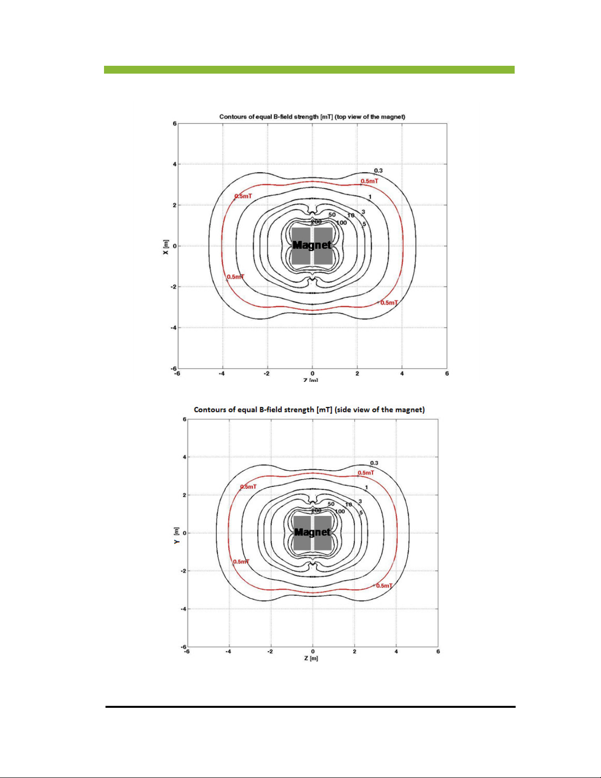
Fringe Field Lines —Top and Side Views
Chapter 2: Safety Information and
ViewRay Inc. MRIdian® system L-0009 Release 4.5 43
Page 62

Chapter 2: Safety Information and Alerts
2.9.2 MR Restricted Access Sign
The following sign must be posted at all entrances to the 5-gauss and higher area. No MR
workers or patients should be allowed in this area without MR training, pre-screening and
authorization.
2.10 Exposure to RF Electromagnetic Fields
During the course of an MR scan, the patient's body absorbs energy from the RF field
generated by the transmitter coil. The RF field causes excitation of the atomic nuclei in the
human body, and the receive coils receive the returned signals.
44 MRIdian® system L-0009 Release 4.5 ViewRay Inc.
Page 63
Chapter 2: Safety Information and
2.10.1 Warming of Body Tissue
During the radio frequency pulses that are part of the MR scan, the patient’s body is exposed
to RF output in the form of electromagnetic radiation. The output absorbed by the patient
depends on body weight and is indicated as the
W/kg.
The specific absorption rate obtainable with the MRIdian® system is set to
the acceptable limits for normal operating mode, according to currently
publi
shed literature including IEC guidelines.
specific absorption rate (SAR), expressed as
The body temperature increases when the SAR r
cooling capacity. The patient’s ability to dissipate surplus heat is made more difficult as the
room temperature and relative humidity increase. Ensure the room temperature does not
exceed 24C (75F) and the relative humidity does not exceed 60%.
The use of an air conditioning system and/or appropriate temperature control devices may be
necessar
The Operator is responsible for monitoring the functionality of the air conditioning system as
ell as the temperature and relative humidity inside the treatment room for the comfort and
w
safety of patients.
The energy absorbed in the course of MR imaging warms the tissue. The heat generated is
dissip
perspiration and blood flow.
y to ensure the appropriate temperature and humidity.
If the room temperature and/or relative humidity is higher than the levels
specified above, compliance with the SAR limits according to FDA (Food and
Drug Administration) or IEC (International Electrotechnical Commission)
regulations may no longer be assured.
ated by the thermoregulation mechanisms of the patient, such as, increased
ate exceeds the limit set by the body’s
Unacceptably high local SAR values may lead to RF burns. At high values, the SAR that is
xposed evenly across the body adversely affects the patient's thermoregulation and the
e
cardiovascular system.
The body temperature increases if the patient absorbs more energy per unit of time than can
be dissip
increase in temperature.
ViewRay Inc. MRIdian® system L-0009 Release 4.5 45
ated through thermoregulation. The longer this condition lasts, the greater the
Page 64

Chapter 2: Safety Information and Alerts
2.10.2 Noticeable Effects on the Patient
During MR imaging, patients may experience heat sensations on the skin and may begin to
perspire. Their pulse rate may increase as well. The individual effects vary from patient to
patient. Following the MR imaging, the body will cool off and the pulse rate will return to
normal.
2.11 Peripheral Nerve Stimulation (dB/dt)
Magnetic Resonance Imaging is based, in part, on the use of time-varying magnetic fields
(dB/dt) which are produced by electric current field gradient coils.
These field gradients must be switched on and off rapidly (typically in less than a thousandth
of a second) to obtain images. And, by electromagnetic induction they generate electric fields
in the conducting tissues of the body.
These induced electric fields in the body can cause uncomfortable stimulation of the
peripheral nerves which is often perceived by the patient as a tingling or tapping sensation.
Although this peripheral nerve stimulation may cause some discomfort for the patient, it is
not harmful.
The MRIdian® MRIS uses a high-performance gradient system which has the potential to
induce peripheral nerve stimulation (PNS) in patients and MR workers during scans.
2.11.1 Operating Modes
The MRIdian MRI has two operating modes:
• Normal Mode
• First Level Controlled Operating Mode
Normal Mode is a lower gradient power mode.
First Level Controlled Mode has a higher gradient output. The higher the gradient output the
higher the probability and the intensity of peripheral nerve stimulation. Gradient output levels
are based on current literature related to safety, including IEC guidelines
Main Magnet (Bo): The MRIdian MRIS operates in the Normal Operating Mode for Bo at all
times. According to IEC 60601-2-33 (3rd Edition), a field strength of less than 3T is in the
Normal Operating Mode. The MRIdian® system operates at 0.35T.
46 MRIdian® system L-0009 Release 4.5 ViewRay Inc.
Page 65
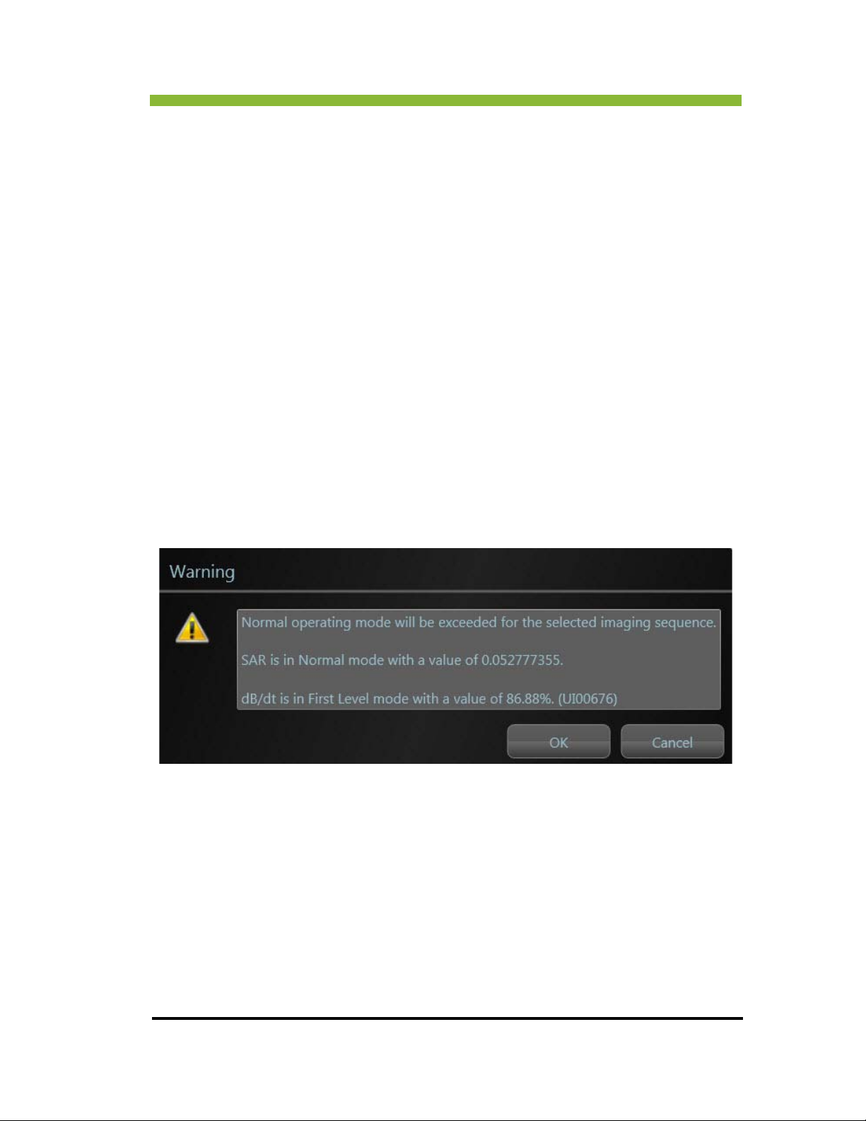
Chapter 2: Safety Information and
SAR: The MRIdian MRIS operates in the Normal Operating Mode for SAR at all times.
According to IEC 60601-2-33 (3rd Edition), a SAR of less than 2 W/kG in the whole body is in
the Normal Operating Mode. Because of the 0.35T field strength, the MRIS does not exceed
1.2 W/kG, and is therefore always in the Normal Operating Mode.
dB/dt: Th
for dB/dt. Patients may experience peripheral nerve stimulation, or a twitching sensation,
during scans. In situations where the system enters the First Level Controlled Mode for dB/dt,
the operator will receive a dialog box warning indicating that the particular sequence is in the
First Controlled Mode for dB/dt. The operator is required to acknowledge this warning before
continuing the scan. Operation of the system in the Second Controlled Mode for dB/dt is
prevented by software controls.
e MRIdian 0.35T magnet is capable of operating in the First Level Controlled Mode
2.11.2 First Level Controlled Operating Mode
All treatment cinés are in the First Level Controlled Operating Mode for dB/dt. See
"Peripheral Nerve Stimulation (dB/dt)” on page 46
The system alerts the operator when a scan will enter the First Level Controlled Operating
by displaying the following warning:
Mode
You must OK the First Level Controlled Operating Mode by taking the deliberate action of
Clicking > OK.
You must inform your patient of the possibility of peripheral nerve stimulation and remain in
onstant audio and visual contact with the patient.
c
Operators must receive training in methods to minimize adverse health effects of high
adient magnetic fields.
gr
ViewRay Inc. MRIdian® system L-0009 Release 4.5 47
Page 66

Chapter 2: Safety Information and Alerts
It is the responsibility of the operator to decide whether to scan using the First Level
Controlled Operating Mode considering both the possible need for physiological monitoring
and the potential risks versus benefits to the patient.
To reduce the physiological effects, patients should be cautioned to remain still while the
ystem is in the First Level Controlled Operating Mode.
s
Compatibility of tools and accessories may also decr
magnetic field increases. Care should be taken when using tools and accessories in First Level
Controlled Operating Mode.
There may be country-specific regulations and guidelines on patient
monitoring during First Level Controlled Operating Modes.
ease as the time-varying (gradient)
2.12 Current Loops
Dangerous current loops may be generated when parts of the patient’s
body touch. These loops may lead to burns or increase the probability
timulation.
of s
Ensure the patient’s body parts are not touching to form current loops and explain to the
patient not to allow body parts to make contact during the treatment imaging.
Ensure the patient does not wear wet clothing or clothing dampened by perspiration.
Ensure sufficient ventilation during the imaging and treatment.
Use positioning aids such as blankets or dry material that are both permeable to air and at
least 5 millimeters thick.
Use caution when using transdermal patches because they may cause burns to underlying
skin.
48 MRIdian® system L-0009 Release 4.5 ViewRay Inc.
Page 67
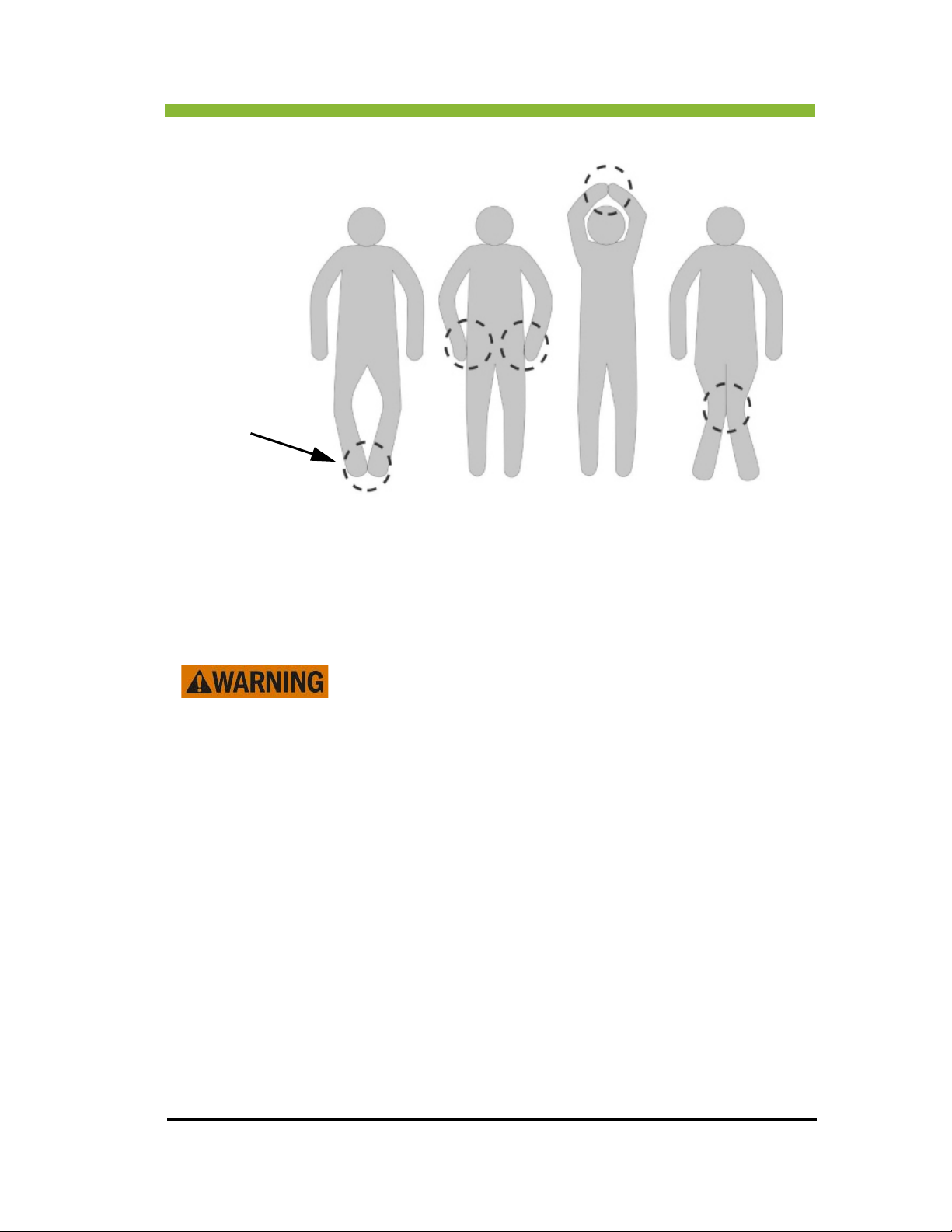
Current Loops
can form anywhere
body parts
make contact.
Chapter 2: Safety Information and
2.13 Effects of Antenna
Looped cables, such as RF coils, ECG lines, and patient monitoring
devices, show an exceptionally high capability of receiving RF
fields. The loops will function as r
to levels leading to second or third degree skin burns.
Ensure that receive coil cables and any accessory cables do NOT create a loop.
Position the receive coil cable in a way which does not contact the patient’s skin.
Avoid placement of the patient’s body or extremities against the RF transmit coil surface.
Ensur
examinations.
MR w
minimized by staying inside the Treatment Control Room which is outside the 5 Gauss line.
e there are no unconnected receive coils or electric cables present during
orkers may also be exposed to heating caused by RF radiation. Exposure can be
eceive antennas and may warm
ViewRay Inc. MRIdian® system L-0009 Release 4.5 49
Page 68

Chapter 2: Safety Information and Alerts
2.14 Risks of Non-MR Safe Monitoring and Interventional Devices
Non-MR safe patient monitoring devices may measure erroneous
values because of RF field interference.
Use only MR-safe vital parameter measurement devices for monitoring. Only equipment
labeled as MR-safe by its manufacturer should be used with the MRIdian® system.
Ensure any ECG electrodes and leads are labeled as MR-safe by the manufacturer
and that they have not passed their expiration date.
Ensure any interventional device used has shielded electronics to reduce
interference with MR signal.
Follow your facility's protocol for monitoring sedated or unconscious patients.
These patients are unable to alert operators of excessive heating and associated
tissue damage so they must be monitored closely.
2.15 Hazardous Noise Levels
The MRIdian® system generates substantial acoustic noise in the
treatment room during treatment. Temporary or permanent
hearing
The recommendations below are based on measurements made on the MRIdian MRIS in the
mode pr
scale, dB, is used when describing sound power. Sound levels are designated by an A
indicating the sound was measured on the A scale of a standard sound level meter at slow
response. The FDA released updated guidelines for acoustic noise levels associated with the
operation of MR systems, on July 14, 2003, as follows: a MR device should not produce noise
having a peak unweighted sound pressure level greater than 140 dB, or A-weighted root
mean square (rms) sound pressure level greater than 99dBA with hearing protection in place.
oducing the worst case clinical scan conditions [ISO 1999.] The logarithmic decibel
loss can occur if adequate hearing protection is not used.
orm patients about the noise generated during treatment.
Inf
50 MRIdian® system L-0009 Release 4.5 ViewRay Inc.
Page 69

Chapter 2: Safety Information and
Use only MR-safe hearing protection, either a headset or earplugs, to protect
patients against injury. Special training must be provided to operators for the
proper placement of hearing protection, especially for cases where standard ear
cuffs, plugs, or other protection cannot easily be applied.
The patient and any MR worker present in the treatment room during MR imaging
must wear hearing protection.
Sound levels in the control room with all doors closed should not exceed 75dB(A).
Operators should use hearing protection as required per site. The exposure of pa
tients and MR workers to noise may be regulated through local, state, and countryspecific laws.
Hearing protection of 20 dB must be used in the treatment room during scanning
to reduce A-weight rms sound pressure levels to 99dB(A).
Anaesthetized and sedated patient may have less than normal protection against
high sound pressure and therefore must be provided with hearing protection.
-
Inform patients about the noise the system makes and caution them to remain still
to avoid injuries.
Infants, young children, pregnant women and their fetuses, and the elderly may
experience high levels of anxiety which increases their perception of sound
pressure levels. Take special precautions to provide sufficient hearing protection
for these patients.
2.16 Magnet Quench
Spontaneous magnet quenches are rare, but you should know how to respond if one does
occur.
A magnet quench is the rapid release of the gaseous cryogens that produce the
superconducting magnetic field. A magnet quench releases helium vapor that escapes
through the quench vent; however, in order to prevent the risk of asphyxiation due to oxygen
displacement, personnel should evacuate the area during a quench.
Each of the two superconducting magnets is equipped with a burst disk sensor that will
detect the pressure change caused by the onset of a quench and will open the interlock and
retract the sources, putting them into the OFF and LOCKED state. The fault is logged by the
system. ViewRay Service must be called to clear the fault and restore the system.
Warning signs that a quench is happening are:
ViewRay Inc. MRIdian® system L-0009 Release 4.5 51
Page 70

Chapter 2: Safety Information and Alerts
• Noise
• Condensation on the quench vent
• Warning from the system that the magnetic field has collapsed
Also see "Emergency Magnet Shutdown” on page 63.
Follow the instructions for your treatment room oxygen monitor and
ensure everyone is evacuated from the treatment room if the oxygen
monitor alarm is triggered.
2.16.1 Half Quenches
Because the MRIdian® system contains two separate magnets, a half quench is possible. If
only one magnet quenches, the 5 gauss (0.5mT) line shifts.
2.16.2 Gauss Line After a Patient-End Magnet Quench
Gauss lines in the X/Y-Z Plane
52 MRIdian® system L-0009 Release 4.5 ViewRay Inc.
Page 71
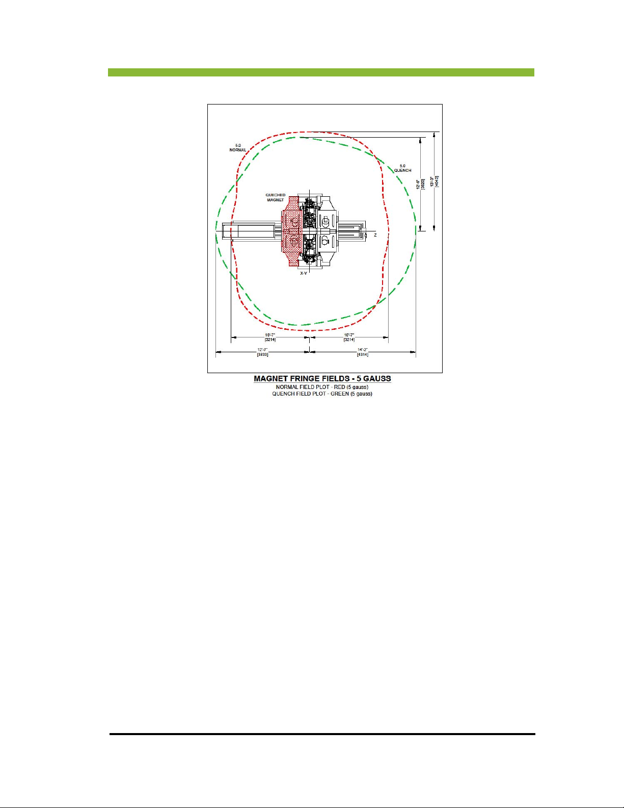
Chapter 2: Safety Information and
Gauss Lines in the Z = 0 plane after a half-magnet quench
ViewRay Inc. MRIdian® system L-0009 Release 4.5 53
Page 72
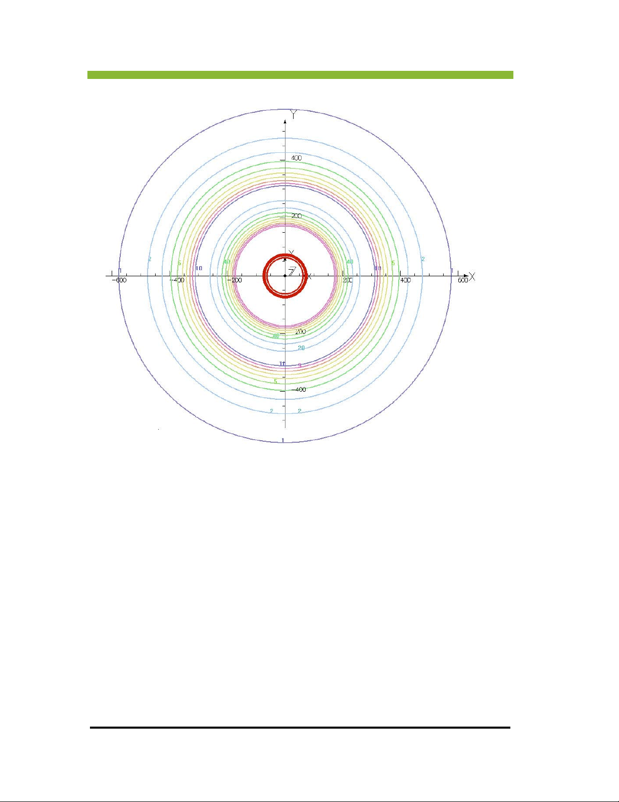
Chapter 2: Safety Information and Alerts
54 MRIdian® system L-0009 Release 4.5 ViewRay Inc.
Page 73
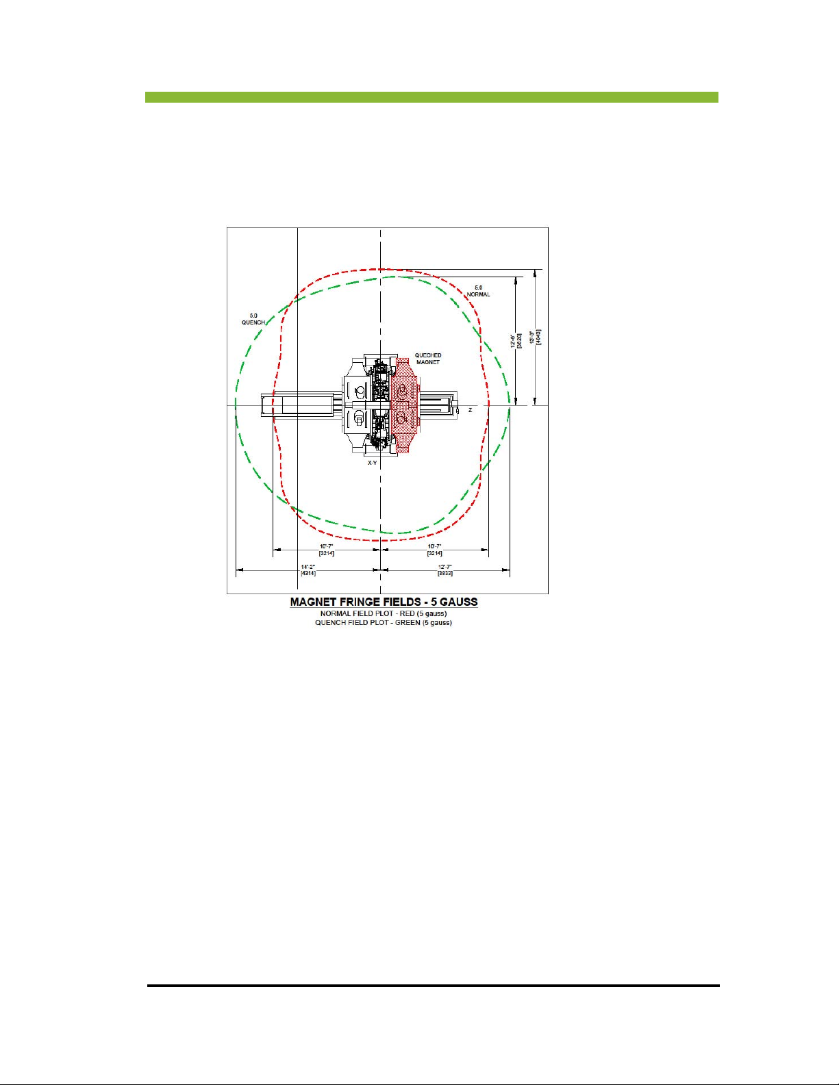
Chapter 2: Safety Information and
2.16.3 Gauss Line After a Service-End Magnet Quench
Gauss lines in the Z/Y - Z plane
Gauss Lines in the Z = 0 plane after a half-magnet quench
ViewRay Inc. MRIdian® system L-0009 Release 4.5 55
Page 74
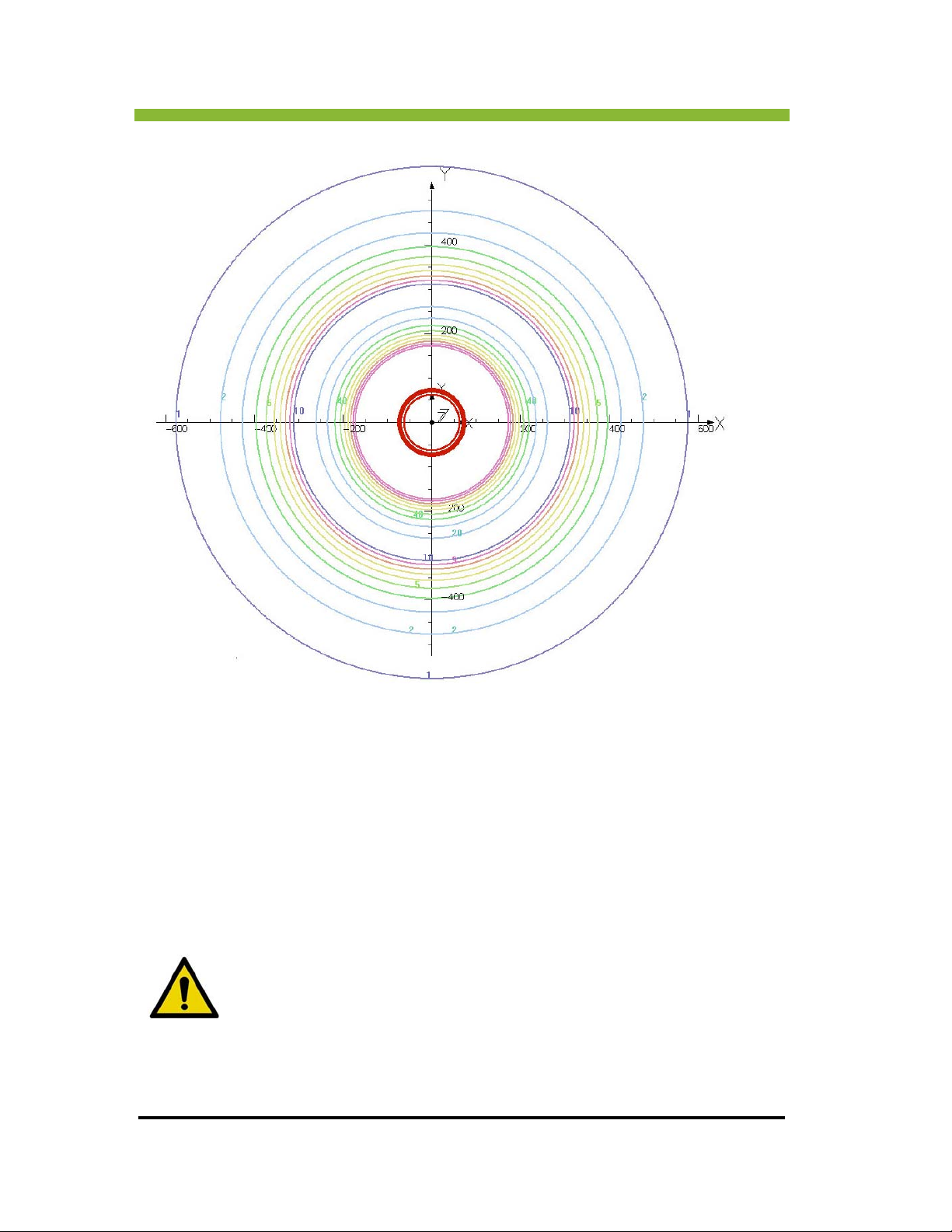
Chapter 2: Safety Information and Alerts
2.17 Fire Safety in the Treatment Room
In the event of fire, the fire has to be extinguished with methods safe in an MR environment.
Firefighters must be able to take appropriate MR-safe actions immediately. Your local
firefighting responders must be familiar with your MR system, its location, and the specialized
firefighting techniques necessary for safety in an MR environment.
Before initial start-up of the MRIdian® system, the facility using the
system is responsible for informing the fire department about the MR
system and the hazards of using magnetizable objects.
56 MRIdian® system L-0009 Release 4.5 ViewRay Inc.
Page 75

Chapter 2: Safety Information and
The following devices/materials may be used for firefighting:
Non-magnetic CO
extinguisher
2
Self-contained, non-magnetic compressed air respiratory apparatus
Airtight chemical protective suit
2.18 Measurement Phantom Safety
Phantoms are filled with water-based nickel sulfate solutions. Other
components may include sodium chloride, sodium phosphate buffers, as
ell as copper sulfate, lactates and acetates.
w
The fluids are sealed in the measurement phantoms. When measurement
phantoms are
the RF coils, there is no physical contact with measurement phantom fluids.
used as intended, within the scope of quality assessments of
2.18.1 Contact with Phantom Fluid Spills
When handling phantom fluid spills wear protective clothing
(gloves, work coat, goggles). and follow the listed precautions:
Wear a mask with a filter for anorganic vapors if aerosols (inhalable droplets)
are formed.
ViewRay Inc. MRIdian® system L-0009 Release 4.5 57
Page 76
Chapter 2: Safety Information and Alerts
Do not use damaged phantoms.
Avoid skin contact with phantom fluid.
Change contaminated clothing immediately.
Do not eat, drink, or smoke.
Ensure phantom fluid does not enter the waste water.
Dispose of phantom fluid in compliance with local and national regulations.
Follow the instructions in the Material Safety Data Sheet that was included with
the phantom.
2.18.2 Risks Due to Aerosol Formation
If phantom fluid has escaped, inhalable droplets (aerosols) containing nickel may form if there
is a fire or if atomization has been caused by strong air currents. Carcinogenic effects cannot
be ruled out if these aerosols are absorbed by the body.
2.19 Radiation Precautions
The MRIdian® system delivers ionizing radiation
during treatment delivery.
Extended exposure to the radiation beam can cause
erious injury or death. The treatment room
s
unoccupied except for the patient being treated
during the BEAM ON state.
2.19.1 Radiation Safety
The MRIdian system uses 3 sealed sources of 60Cobalt for the delivery of radiation therapy.
Each source has an activity level of 12,000-15,000 curies (Ci) at the time of installation. See
“General MRIdian® System Safety” on page 23.
must be
58 MRIdian® system L-0009 Release 4.5 ViewRay Inc.
Page 77
Chapter 2: Safety Information and
When the sources are retracted and locked into the shielding heads and in the Off position,
radiation exposure in the treatment room is reduced to background levels, and the room is
safe for cleaning and patient set-up activity. When the sources are moved to the Beam Hold
position, they are still retracted, but not locked.
Special tools are required to access the source. These t
secured by a trustworthy and responsible person designated by the site.
ools are provided by ViewRay and
ALERT: When the sources are moved to the Beam On position for treatment,
high levels of radioactivity are present and no one except the patient being
eated should be in the treatment room.
tr
Verify that the patient identification and approved treatment plan match
prior to starting therapy to avoid unnecessary radiation exposure and the
possible irradiation of healthy tissue.
2.19.2 Exposure Control for Operators
Radiation dose is determined by the amount of time you are exposed to a radioactive source,
the distance you are from that radioactive source, and any intervening shielding.
By minimizing the time you are near a radioactive source, using shielding, and maintaining
tance from the source, your total radiation exposure will remain well within the acceptable
dis
and safe level.
Consult your facility’s Radiation Safety Officer if you want more information about the
principles of
radiation exposure and dose.
2.19.3 Audible Radiation Alert
Each delivery station is equipped with an audible radiation alert that beeps whenever the
radiation beam is on.
ViewRay Inc. MRIdian® system L-0009 Release 4.5 59
Page 78

Chapter 2: Safety Information and Alerts
2.19.4 Radiation Safety Interlocks
The Radiation Safety Interlocks on the MRIdian® system are designed to control radiation
exposure by automatically retracting the source into the Off position whenever any of the
following occur:
The door to the treatment room is opened
There is a power outage
The E-Stop button is pushed
The system detects a malfunction
Follow your facility's Radiation Safety Program and exposure monitoring requirements at all
tim
es when entering the treatment room.
Do not disable any system interlocks, or attempt to operate the system if
the interlocks are not functioning properly.
2.20 Emergency Response Plans
Each facility should develop emergency response plans for the MRIdian® System.
The Emergency Response Plans should take into consideration the following:
Unintended radiation exposure: See “Unintended Radiation (Stuck Source) Exposure” on
page 61.
Emer
gency Magnet Shutdown: See “Emergency Magnet Shutdown” on page 63.
Rescuing the patient: See “Rescuing the Patient in an Emergency” on page 64.
60 MRIdian® system L-0009 Release 4.5 ViewRay Inc.
Page 79
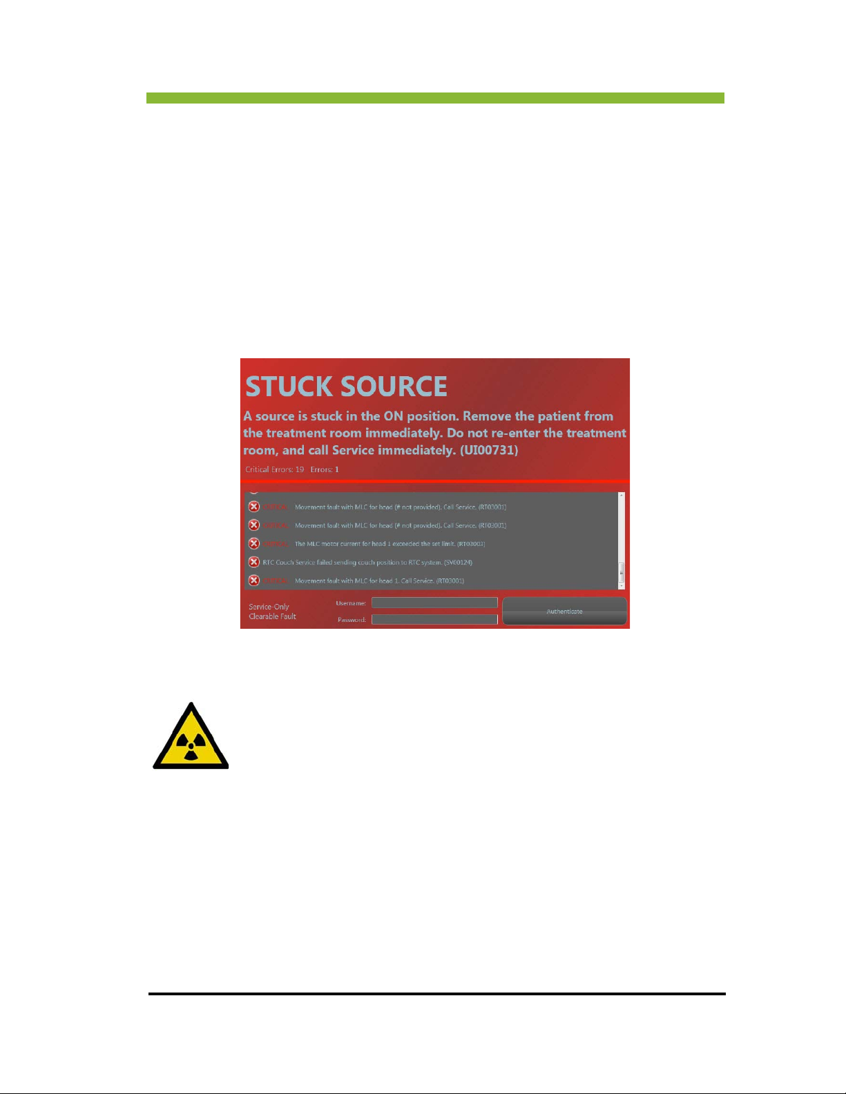
Chapter 2: Safety Information and
Sites should identify and plan emergency medical procedures that are safe in the presence
of the magnetic field, so the appropriate and necessary treatment can be given to a
patient who feels ill or is injured during an examination.
2.21 Unintended Radiation (Stuck Source) Expo-
sure
When the MRIdian® RT Control system detects a stuck source, the operator receives this
system message on the user interface.
The following events are initiated by the system:
1. Sources are moved to the OFF position by a dedicated pneumatic system.
2. Patient table retracts from the bore.
3. Gantry rotates and places the head with the movement fault into the 90
position where gravity can assist in moving the source into the off position.
4. Multi-Leaf Collimators close.
5. The Auxiliary Radiation Shield closes.
6. A system inhibit interlock is enabled to prevent treatment.
After the system retracts the patient table, do the following:
ViewRay Inc. MRIdian® system L-0009 Release 4.5 61
0
Page 80
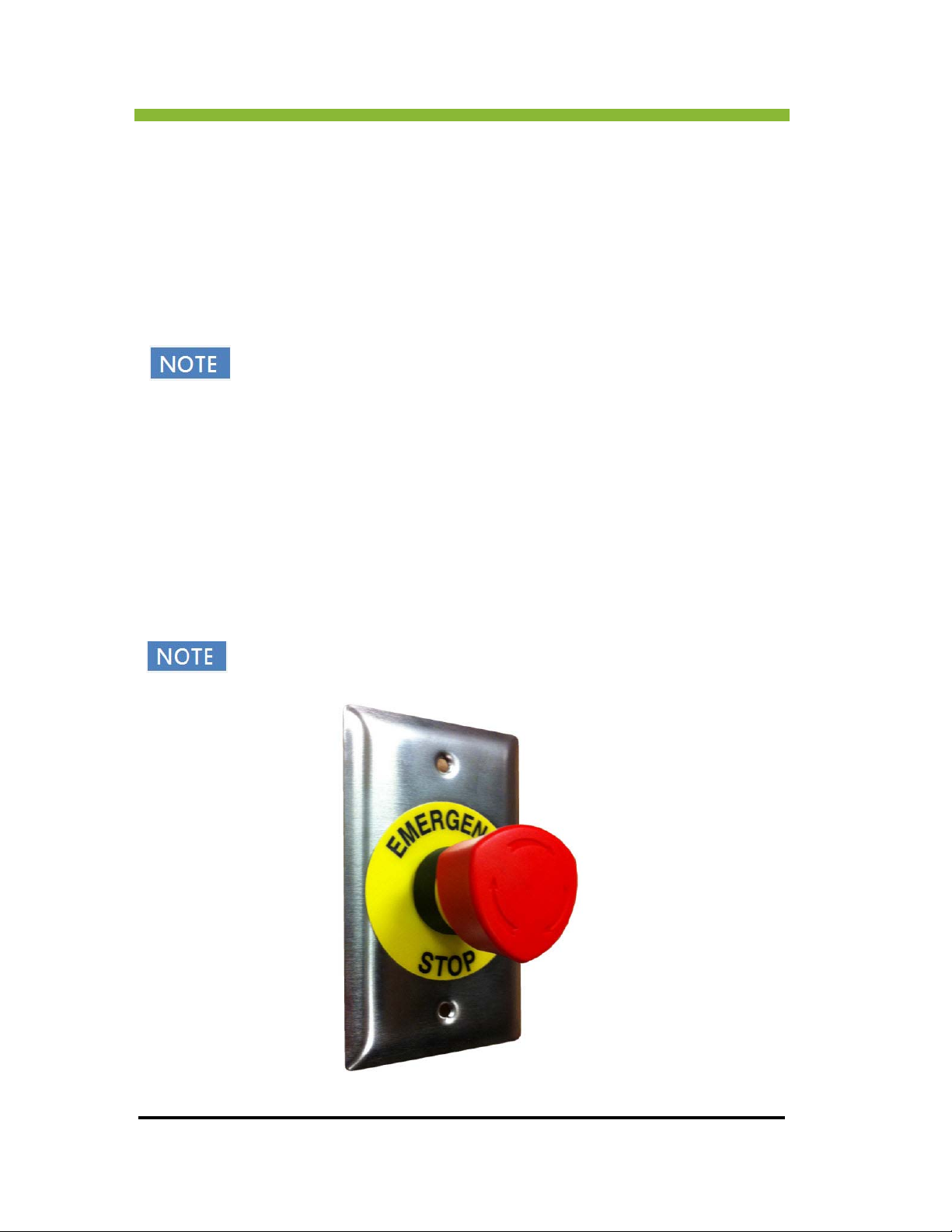
Chapter 2: Safety Information and Alerts
Remove your patient from the treatment room.
Close the treatment room door.
Contact your RSO and follow your facility
Contact ViewRay Service.
If the gantry control system is also inoperable and does not move the stuck
source to the loading position, a mechanical retraction procedure can be
initia
ted. This should only be done with consultation and oversight by your
facility's RSO. This procedure is described in "Mechanical Source Retraction
Procedure” on page 447 which is provided as an attachment to this manual.
The provided non-magnetic Allen wrench needed for this procedure must be
ept close to the treatment room entrance at all times.
k
’s Emergency Response Plan.
2.22 Using the E-Stop in an Emergency
Pressing the E-Stop will retract the sources to the locked, fully shielded position, and stop any
patient couch movement. There are four E-Stop buttons in the treatment room and one on
the Treatment Control Panel.
The E-Stop must be reset after use. Turn the knob clockwise to reset.
62 MRIdian® system L-0009 Release 4.5 ViewRay Inc.
Page 81

Chapter 2: Safety Information and
2.23 Emergency Magnet Shutdown
If someone is trapped inside the magnet, pushing the MAGNET EMERGENCY DISCHARGE
BUTTON (see next page) will initiate an emergency quench of the magnet. The term “quench”
is used to describe the rapid boil off of the cryogens (subzero-temperature liquid refrigerants)
that keep the magnet cooled and in a superconducting state. Without cryogens the magnet
loses its magnetic field. See “Emergency Quench Procedure” on page 64, and "Rescuing the
Patient in an Emergency” on page 64.
All cryogen liquids produce large volumes of gas when they vaporize.
When a quench is initiated you MUST evacuate the treatment room immediately to avoid
asphyxiated in the event the gases fail to vent properly out of the treatment room and
being
displace all the oxygen.
Skin contact with cryogens will cause cryogenic burns of the skin and freeze underlying tissue.
2.23.1 Magnet Emergency Discharge Button
ONLY USE THE MAGNET EMERGENCY DISCHARGE BUTTON FOR EMERGENCIES WHERE
IMMEDIATE SHUTDOWN OF THE MAGNET IS NEEDED, SUCH AS A PERSON TRAPPED IN THE
BORE OR PINNED TO THE MAGNET BY A METAL OBJECT.
Costly reactivation activities are required after a magnet quench and the
system will be inoperable for at least one week.
ViewRay Inc. MRIdian® system L-0009 Release 4.5 63
Page 82

Chapter 2: Safety Information and Alerts
2.23.2 Emergency Quench Procedure
1. Push the Magnet Emergency Discharge Button
There will be loud sounds (hissing, gurgling) as the helium boils off. The
magnetic field will decrease to a negligible level within 60 seconds.
2.
Rescue the patient, or, whomever has been trapped by an object and the
force of the magnetic field.
3. Stay out from under the quench vent.
The liquid helium boils off during a quench and condensation will occur on the
quench vent pipe and can drip down and cause frostbite.
4.
Leave the scan room.
The helium is vented outside through the quench vent during a quench.
However, it is possible for helium to escape and fill the room causing oxygen
displacement and the danger of asphyxiation.
5. Call ViewRay Service. It is
Condensation of air oxygen occurs during the escape of ultra cold helium gas and increases
sk of fire. Make sure there is no smoking or use of equipment that discharges electrical
the ri
sp
arks or fire.
Even though the magnet decreases to a negligible level within 60 seconds
after pressing the MAGNET EMERGENCY DISCHARGE BUTTON, it will take five
minut
es for the magnetic field to be completely extinguished.
important to service a quenched magnet immediately.
2.23.3 Rescuing the Patient in an Emergency
IF COUCH MOVEMENT IS CREATING THE EMERGENCY SITUATION
1. Press the E-Stop to stop all couch movement.
2. Rescue the patient.
After the emergency, the E-Stop must be reset. Pull the E-Stop button up to reset.
IF THE PATIENT IS HAVING AN EMERGENCY MEDICAL SITUATION AND YOU MUST REMOVE
PATIENT FROM THE BORE
THE
Press the HOME button on the couch control panel. The couch will automatically withdraw
om the bore.
fr
64 MRIdian® system L-0009 Release 4.5 ViewRay Inc.
Page 83
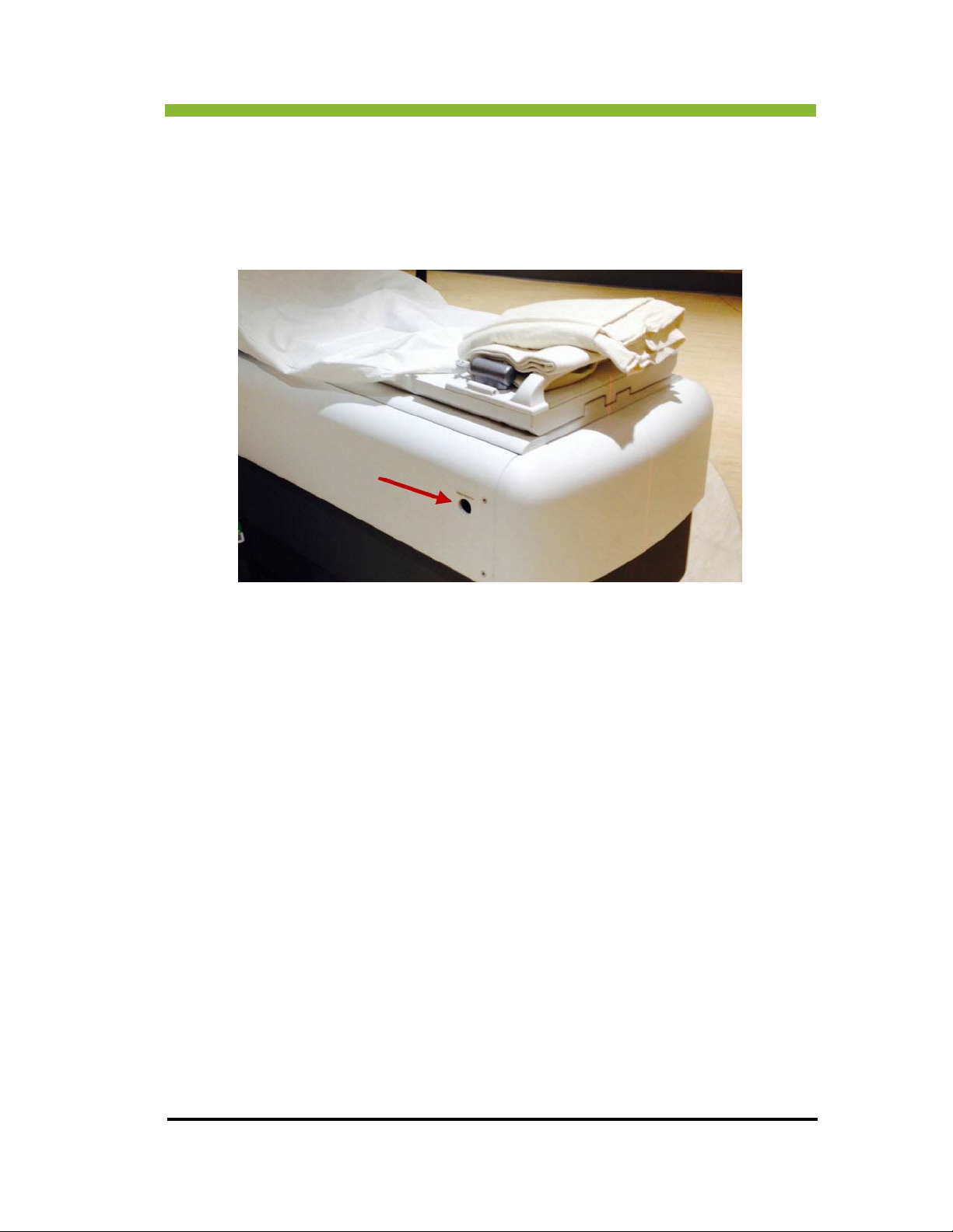
OR
Chapter 2: Safety Information and
Press the Table Release Button on the side of the
out of the bore.
couch and manually pull the patient table
After using the Table Release Button, it must be pressed again to reset.
ViewRay Inc. MRIdian® system L-0009 Release 4.5 65
Page 84

Chapter 2: Safety Information and Alerts
This page intentionally left blank.
66 MRIdian® system L-0009 Release 4.5 ViewRay Inc.
Page 85
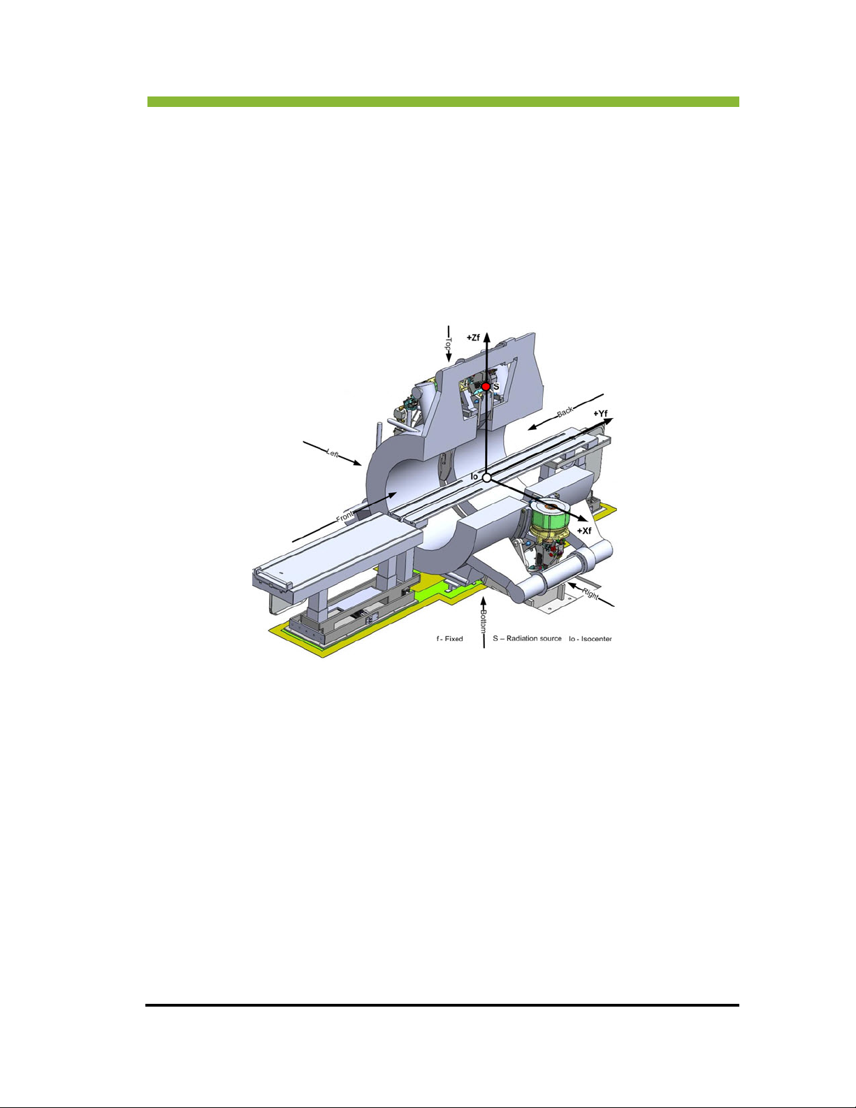
Chapter 3: System Coordinates
Chapter 3: System Coordinates
3.1 MRIdian® System Coordinates
The MRIdian system uses 3-dimensional coordinate systems to fully specify the geometric
location of the data throughout the various systems. This includes: cobalt sources, multi-leaf
collimator positions, radiation beam trajectories, couch location and MR, CT, PET images. The
coordinates’ systems are described in Cartesian coordinates.
3.1.1 Direction Definitions
The front of the machine is defined as the face of the machine where the couch
enters the machine
The back of the machine is defined as the face opposite the front of the machine
The top of the machine is the face of the machine closest to the ceiling
The bottom of the machine is the face of the machine closest to the floor
The left of the machine is on the observer’s left when the observer is standing
facing the front of the machine
The right of the machine is on the observer’s right when the observer is standing
facing the front of the machine
ViewRay Inc. MRIdian® system L-0009 Release 4.5 67
Page 86
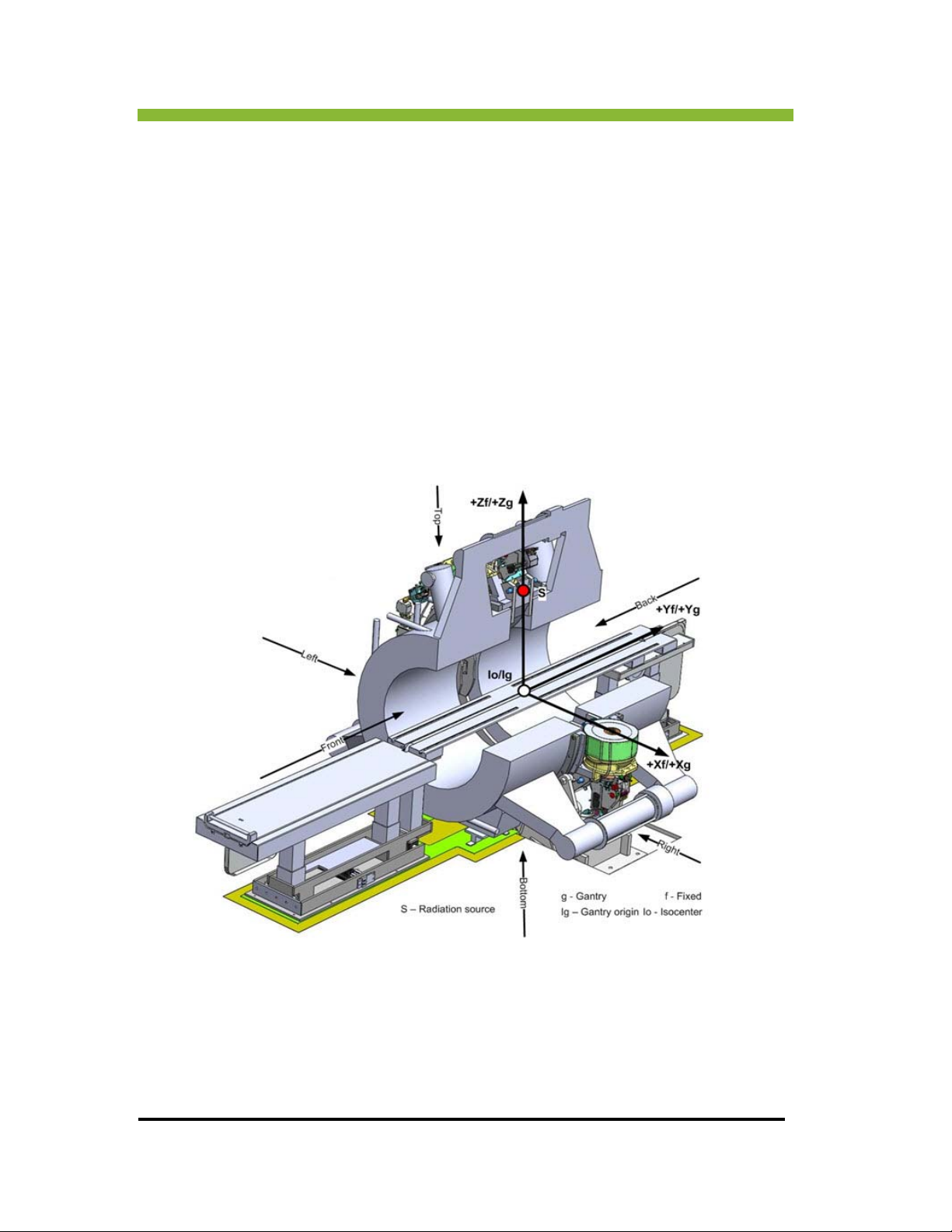
Chapter 3: System Coordinates
In accordance with IEC 61217, the MRIdian® system has a fixed right-handed coordinate
system with the coordinate system origin at the isocenter of the machine.
The “+Z” axis is aligned towards the top of the machine and the “-Z' axis towards the bottom
of the machine. The
aligned towards the front of the machine. The “+X” axis is aligned towards the right of the
machine and the “-X” axis is aligned towards the left of the machine.
The radiation source location for the “0°” position is indicated by the red dot with label “S,”
tha
t is the radiation source is aligned on the “+Z” axis. The isocenter is illustrated by the white
dot with label “Io.”
“+Y” axis is aligned toward the back of the machine and “-Y” axis is
3.1.2 Gantry Coordinate System
The gantry at its “0°” position.
The gantry system is coincident with the fixed system and “Io” and “Ig” are at the same location. The fixed system is the mother system for the gantry system. The gantry coordinate system rotates with the gantry and can only rotate about the Y axis.
68 MRIdian® system L-0009 Release 4.5 ViewRay, Inc.
Page 87
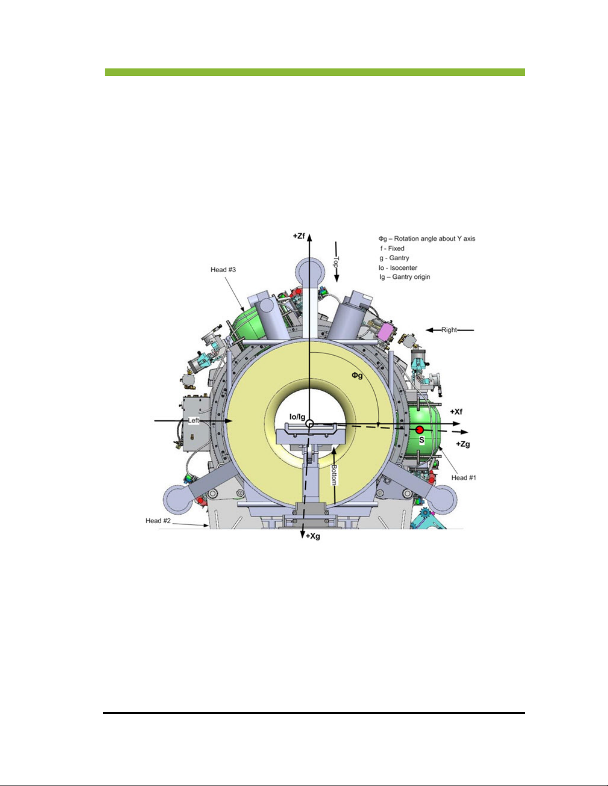
Chapter 3: System Coordinates
In this system the “+Z” axis is aligned towards the top of the machine and the “-Z” axis
towards the bottom of the machine. The “+Y” axis is aligned toward the back of the machine
and “-Y” axis is aligned towards the front of the machine. The “+X” axis is aligned towards the
right of the machine and the “-X” axis is aligned towards the left of the machine.
3.1.3 Gantry Rotation
Positive (Clockwise) gantry rotation is illustrated below. The view is from the front of the
gantry and the angle is slightly greater than 90
.
3.1.4 Beam Limiting Coordinate System
There are three beam-limiting devices (multi-leaf collimators), each located 120 degrees
apart from the other. The beam limiting coordinate system is the same as that of the gantry.
The beam limiting devices rotate with the gantry. When one beam limiting device is at the
“0°” position, its coordinate system is defined with the same axis orientation as the gantry
system. The source “S” and origin “Ib” are at the same position.
The “+Z” axis is aligned to the top of the machine and the “-Z” axis to the bottom of the
ne.
machi
ViewRay Inc. MRIdian® system L-0009 Release 4.5 69
Page 88
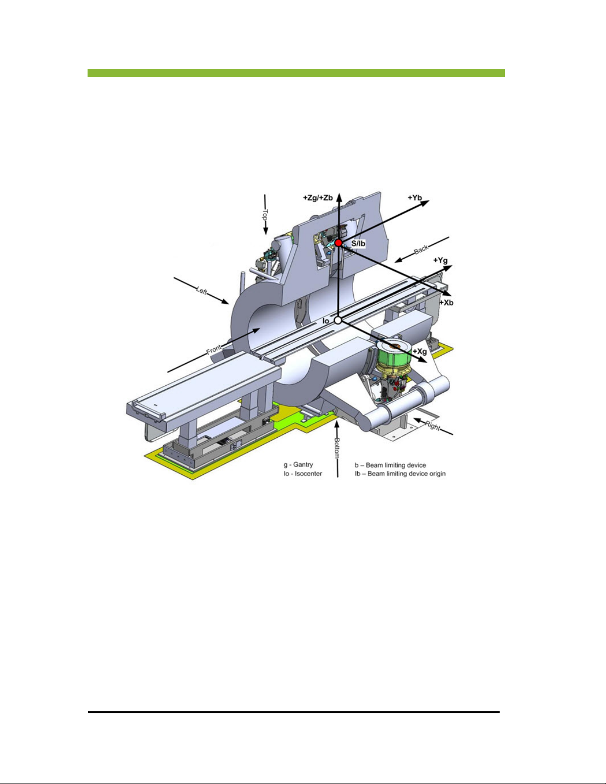
Chapter 3: System Coordinates
The “+Y” axis is aligned to the back of the machine and “-Y” axis is aligned to the front of the
machine.
The “+X” axis is aligned to the right of the machine and the “-X” axis is aligned to the left of
the machi
ne.
3.1.5 Beam’s Eye View of Multi-Leaf Collimator (MLC)
The movement of the MRIdian system's MLC is restricted to the plus and minus “X”
directions.
The MLC leaves below show an open position of
limiting device is shown relative to the couch and gantry. This view of the MLC is considered a
beam's eye because it is pointed toward the gantry isocenter.
70 MRIdian® system L-0009 Release 4.5 ViewRay, Inc.
several leaves. The orientation of the beam
Page 89
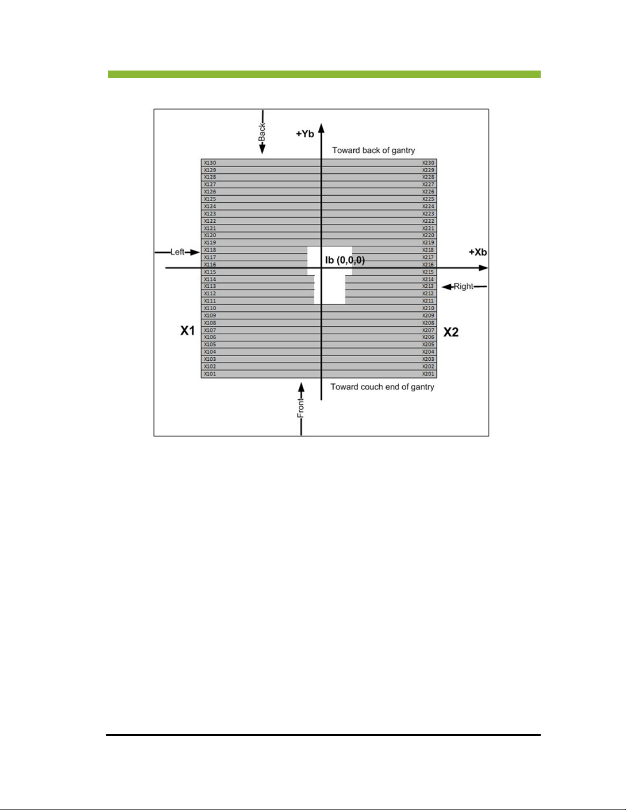
Chapter 3: System Coordinates
3.1.6 Orientation of an MLC Relative to the Gantry
The diagram below shows the orientation of an MLC relative to the gantry. The diagram is at
the “0” gantry position and is looking down at the gantry from above.
ViewRay Inc. MRIdian® system L-0009 Release 4.5 71
Page 90
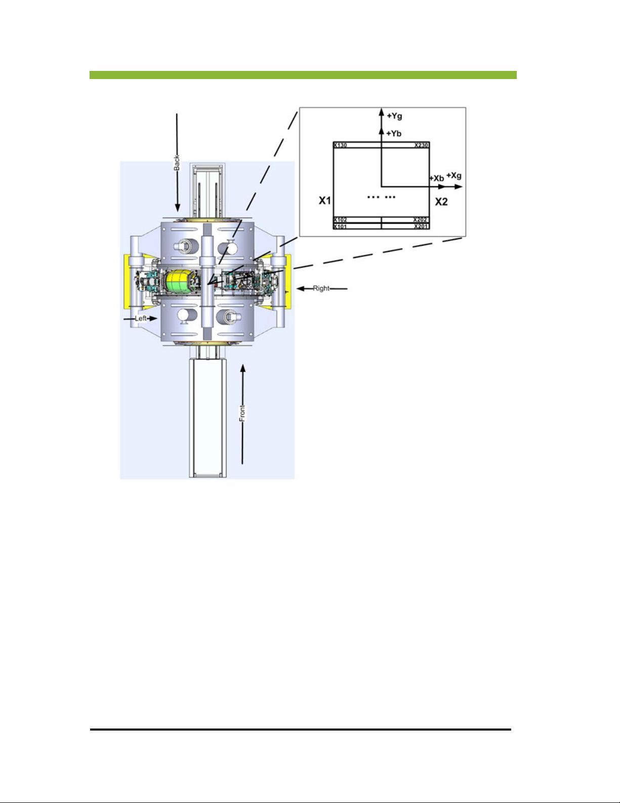
Chapter 3: System Coordinates
3.1.7 MLC Orientation
The figure below shows the MLC and Beam limiting coordinate system for gantry angles of 0,
90, 180, and 270. “ g” is only indicated for the 90°.
72 MRIdian® system L-0009 Release 4.5 ViewRay, Inc.
Page 91
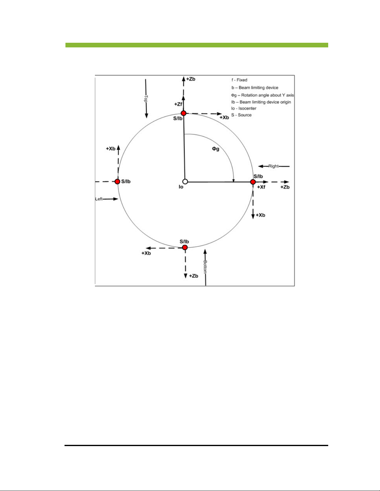
Chapter 3: System Coordinates
3.1.8 Planning and Visualization using Coordinate System
The visualization system displays the Multi-planar reconstruction (MPR) planes as depicted in
the three following diagrams.
In each diagram the image is shown in a black square. The orientation on the user interface
(UI) scr
The axial, lateral and vertical images are always displayed in the fixed coordinate system. Not
that for all three orientations, the patient is shown head first, supine, going into the gantry
from the front.
In this system the “+Z” axis is aligned to the top of the machine and the “-Z” axis to the
bot
the machine and the “-X” axis is aligned to the left of the machine.
ViewRay Inc. MRIdian® system L-0009 Release 4.5 73
een is the same orientation as the square in the top left corner of each diagram.
tom of the machine. The “+/-Y” axis is not visible. The “+X” axis is aligned to the right of
e
Page 92
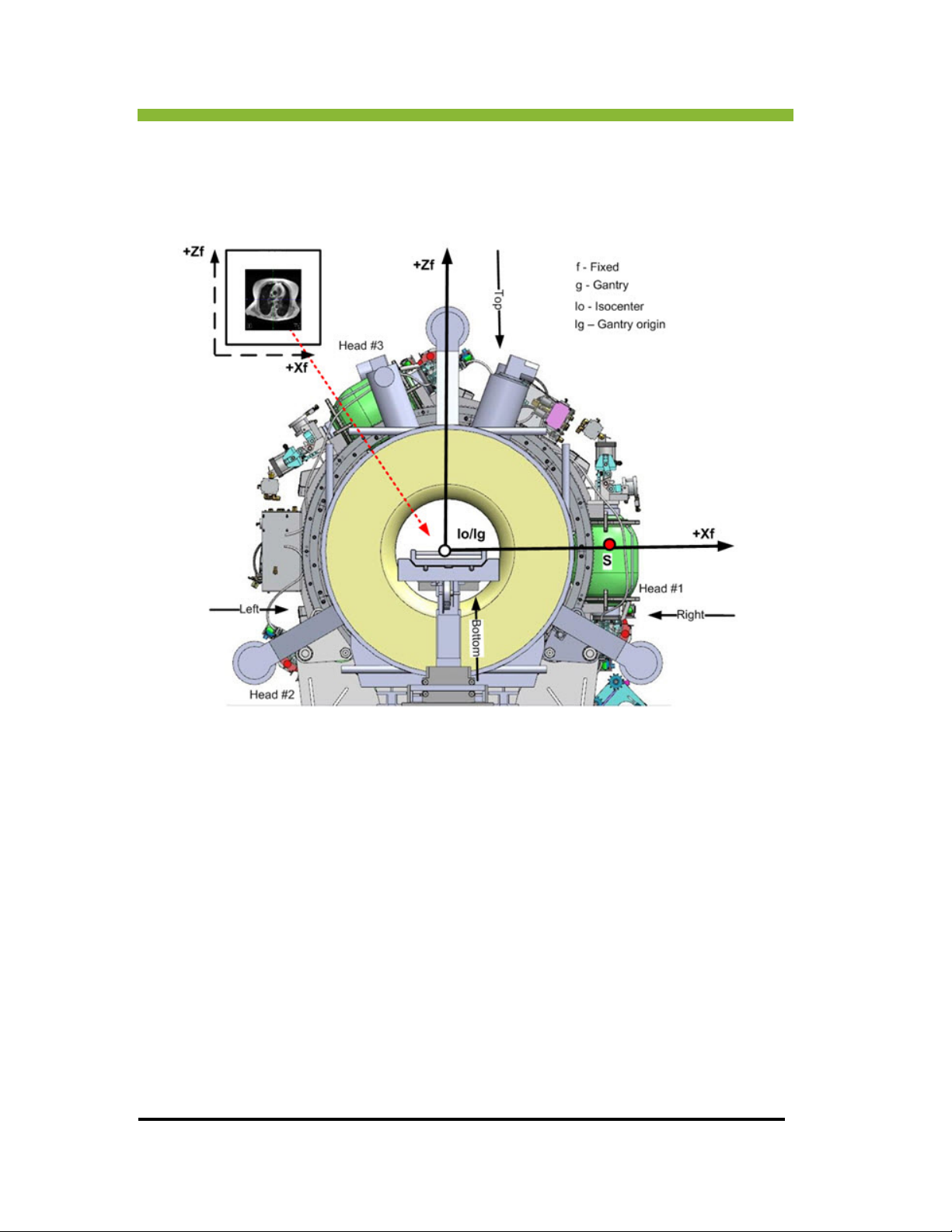
Chapter 3: System Coordinates
Axial MPR Image:
The axial image is viewed as if looking into the gantry from the front.
74 MRIdian® system L-0009 Release 4.5 ViewRay, Inc.
Page 93
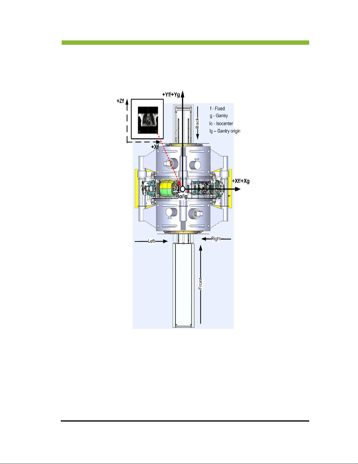
Vertical MPR Image:
Chapter 3: System Coordinates
ViewRay Inc. MRIdian® system L-0009 Release 4.5 75
Page 94
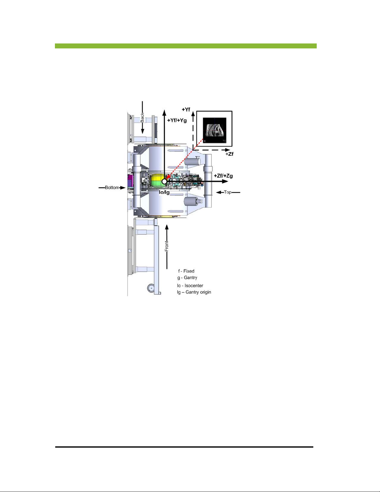
Chapter 3: System Coordinates
Lateral MPR Image:
76 MRIdian® system L-0009 Release 4.5 ViewRay, Inc.
Page 95

Chapter 4: System and Administrative Tasks
Chapter 4: System and Administrative
Tasks
4.1 Starting Up the Planning Consoles
Your system is ready for use after power-on and the Windows® login prompt appears on the
screen.
ter your username and password in the login prompt window.
1. En
Click >
2.
OK.
Once logged in, the MRIdian® software will automatically start up. You may not
exit the MRIdian system software while the system is running. Several system
startup checks will be performed when the software starts up. These checks
include:
Activation check—Checks that the software has been activated for use by ViewRay
personnel during installation.
CRC check—Check
Database check—Ch
database.
Graphics check—Checks that the system has the required Visage dongle for the
visualization rendering license.
Auto-save check—Check
previously shut down due to power-loss or an error and a plan file was auto-saved,
the user will be offered the option to restore the plan to the last auto-saved state.
MRIdian system software is only authorized for use on ViewRay-provided
computers, workstations/hardware. MRIdian system software may not be
ferred to other computer systems. If that is attempted, the software
trans
activation check will fail, preventing startup.
s that system files have not been modified or corrupted.
ecks that the software can connect to the MRIdian system
s if an auto-save file exists. For example, if the system was
ViewRay Inc. MRIdian® system L-0009 Release 4.5 77
Page 96
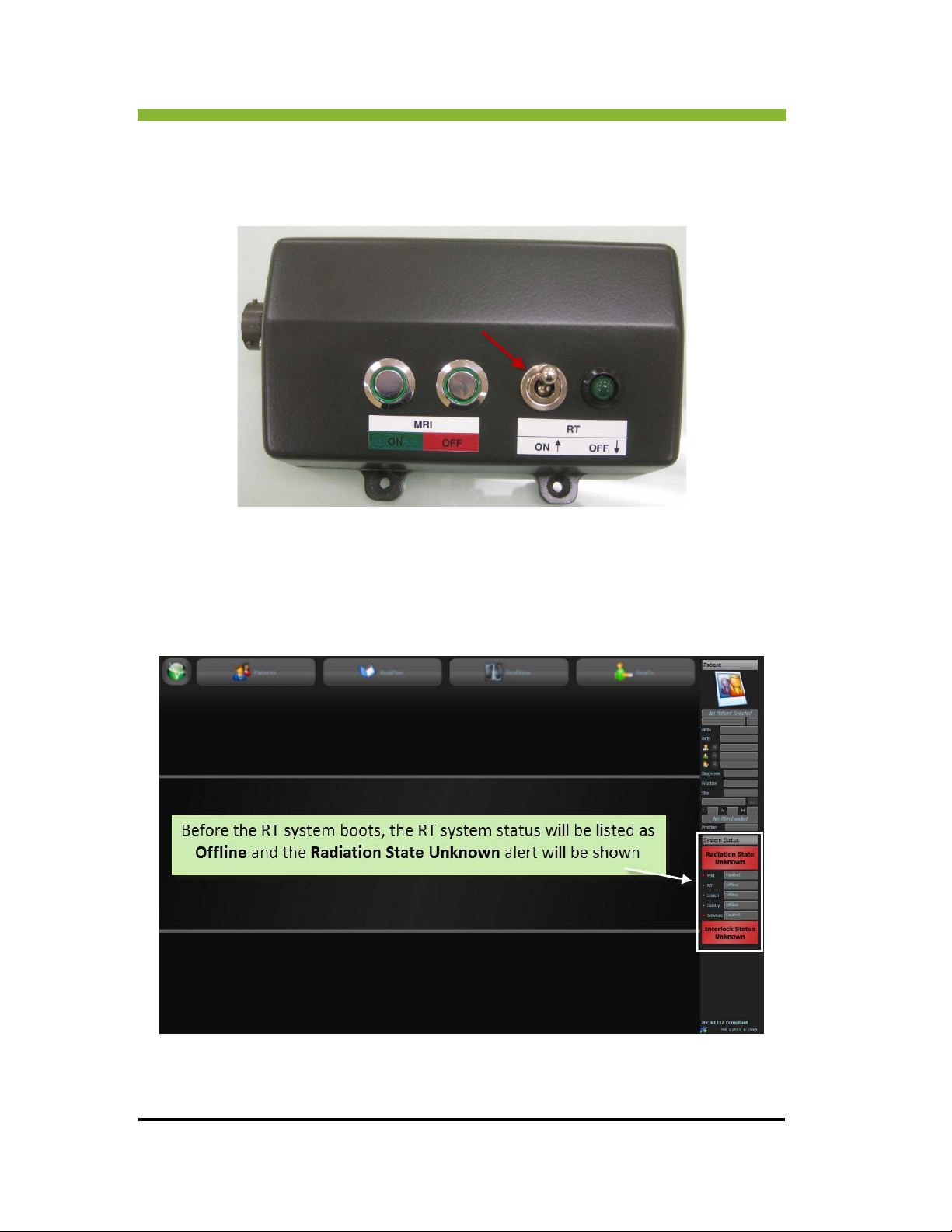
Chapter 4: System and Administrative Tasks
4.2 Starting Up the Delivery System
1. Push the RT toggle switch to the ON position.
2. Push the Power button on the Treatment Delivery computer.
The scr
een will boot up and the RT system will initially be listed as offline.
78 MRIdian® system L-0009 Release 4.5 ViewRay, Inc.
Page 97
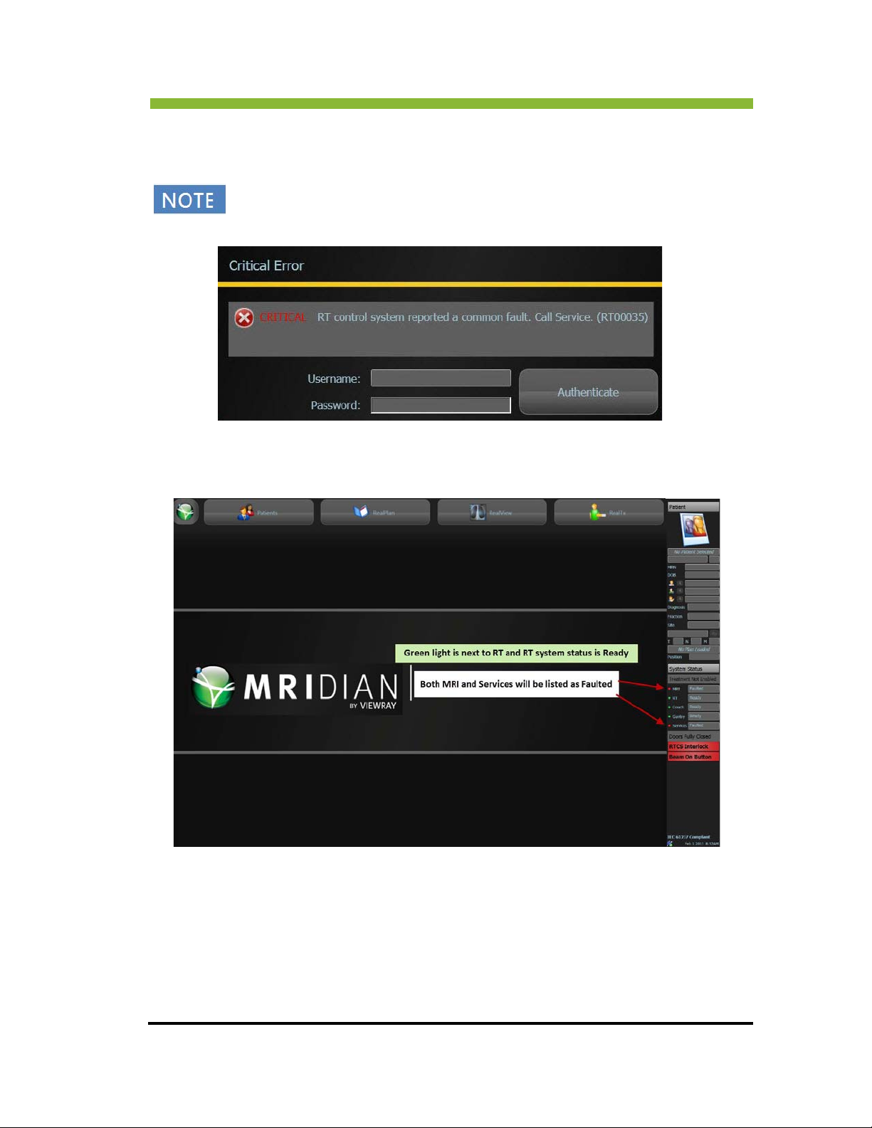
Chapter 4: System and Administrative Tasks
3. Wait for the RT system to boot. It will take approximately 5 minutes for the RT system to
boot.
During the RT booting process RT faults may appear on the UI. Those faults must
be cleared before turning the MRI on.
You will know the RT system has booted properly when the light next to RT is green
and the RT system status is Ready.
ViewRay Inc. MRIdian® system L-0009 Release 4.5 79
Page 98
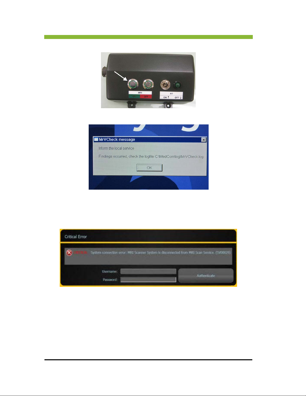
Chapter 4: System and Administrative Tasks
4. Press the MRI ON button on the remote switch box.
5. The MrVCheck message will appear on the Siemens console. Click > OK.
6. While the MRI is booting a critical MRI system connection error will appear on the
RIdian® system UI.
M
7. Enter your username and password and Cli
ck > Authenticate.
A connection request will appear on the Siemens console.
80 MRIdian® system L-0009 Release 4.5 ViewRay, Inc.
Page 99
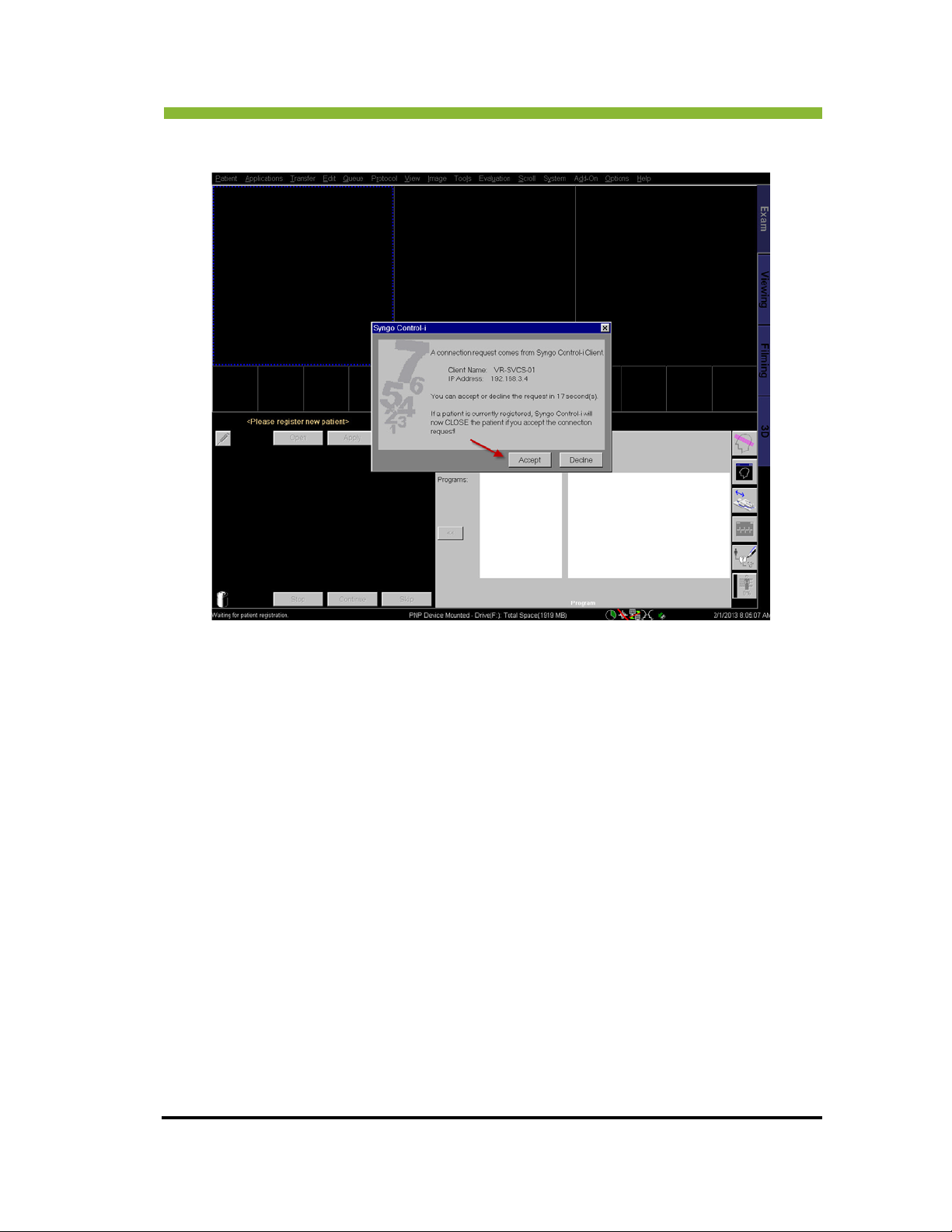
8. Click > Accept on the connection request.
Chapter 4: System and Administrative Tasks
The system is now ready for treatment delivery.
4.2.1 Additional Treatment Delivery Console Checks
When a Treatment Delivery console is started, the following additional treatment-based
checks are performed:
Services Connection Check—The console system will connect to the services
system upon startup. If the connection is not made, the system will disable the
application and retry for several seconds. After a waiting period, the application
will start up as a planning-only system until the next shutdown.
RT Connection Check— If the connection is not made, the system will disable the
application and retry for several seconds. After a waiting period, the application
will start up as a planning-only system until the next shutdown.
Delivery Records Check—Upon connection to the RT system, the console will
check the database for any incomplete delivery records. If any incomplete records
exist, the console will attempt to retrieve the treatment delivery data from the RT
system and then perform post-treatment processing to determine dose. If no
ViewRay Inc. MRIdian® system L-0009 Release 4.5 81
Page 100
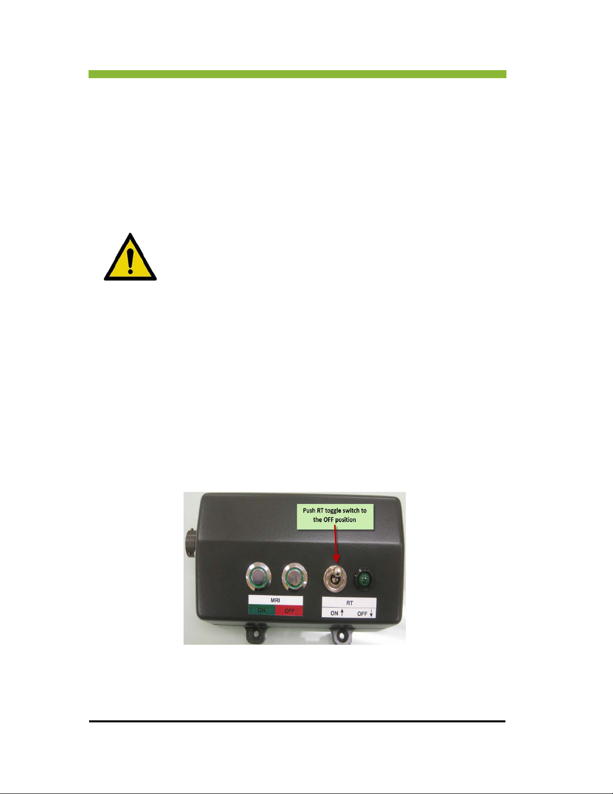
Chapter 4: System and Administrative Tasks
delivery data exists on the RT system, a service user must update the delivery
record.
Unknown Treatment Delivery Data Check—Upon connection to the RT system,
the console will check the RT system for existing delivery data. If the database
contains no records of delivery, but a delivery data set exists on the RT system,
ViewRay Service user must clear the data from the RT system.
4.3 Shutting Down the Planning System
Before shutting down the system, ensure the system is not still processing
or running tasks. Also ensure open plans have been saved, if saving is
ed. It is recommended to perform shut down while on the software
desir
home screen.
To shut down, press the hard power button on the computer console.
At times, the system may automatically restart itself to recover from system errors. In the
ely event that this occurs, call ViewRay Service to report the error and obtain any
unlik
necessary assistance for restarting.
It is recommended to shut down systems on a periodic basis. Shutting down will allow the
Window
When turned off, the system is protected against power surges due to electrical storms or
other conditions.
s operating system to perform file maintenance and “housekeeping” procedures.
4.4 Shutting Down the Delivery and MRI Systems
1. Turn the RT System OFF.
2. From the Siemens console menu bar Click > System.
This will open a dropdown menu.
82 MRIdian® system L-0009 Release 4.5 ViewRay, Inc.
 Loading...